EP1065643A2 - Label sheet - Google Patents
Label sheet Download PDFInfo
- Publication number
- EP1065643A2 EP1065643A2 EP00304742A EP00304742A EP1065643A2 EP 1065643 A2 EP1065643 A2 EP 1065643A2 EP 00304742 A EP00304742 A EP 00304742A EP 00304742 A EP00304742 A EP 00304742A EP 1065643 A2 EP1065643 A2 EP 1065643A2
- Authority
- EP
- European Patent Office
- Prior art keywords
- liner
- overlay
- label
- label sheet
- front side
- Prior art date
- Legal status (The legal status is an assumption and is not a legal conclusion. Google has not performed a legal analysis and makes no representation as to the accuracy of the status listed.)
- Granted
Links
Images


Classifications
-
- G—PHYSICS
- G09—EDUCATION; CRYPTOGRAPHY; DISPLAY; ADVERTISING; SEALS
- G09F—DISPLAYING; ADVERTISING; SIGNS; LABELS OR NAME-PLATES; SEALS
- G09F3/00—Labels, tag tickets, or similar identification or indication means; Seals; Postage or like stamps
- G09F3/08—Fastening or securing by means not forming part of the material of the label itself
- G09F3/10—Fastening or securing by means not forming part of the material of the label itself by an adhesive layer
-
- G—PHYSICS
- G09—EDUCATION; CRYPTOGRAPHY; DISPLAY; ADVERTISING; SEALS
- G09F—DISPLAYING; ADVERTISING; SIGNS; LABELS OR NAME-PLATES; SEALS
- G09F3/00—Labels, tag tickets, or similar identification or indication means; Seals; Postage or like stamps
- G09F3/02—Forms or constructions
- G09F3/0288—Labels or tickets consisting of more than one part, e.g. with address of sender or other reference on separate section to main label; Multi-copy labels
-
- G—PHYSICS
- G09—EDUCATION; CRYPTOGRAPHY; DISPLAY; ADVERTISING; SEALS
- G09F—DISPLAYING; ADVERTISING; SIGNS; LABELS OR NAME-PLATES; SEALS
- G09F3/00—Labels, tag tickets, or similar identification or indication means; Seals; Postage or like stamps
- G09F3/02—Forms or constructions
- G09F2003/0201—Label sheets intended to be introduced in a printer, e.g. laser printer
-
- Y—GENERAL TAGGING OF NEW TECHNOLOGICAL DEVELOPMENTS; GENERAL TAGGING OF CROSS-SECTIONAL TECHNOLOGIES SPANNING OVER SEVERAL SECTIONS OF THE IPC; TECHNICAL SUBJECTS COVERED BY FORMER USPC CROSS-REFERENCE ART COLLECTIONS [XRACs] AND DIGESTS
- Y10—TECHNICAL SUBJECTS COVERED BY FORMER USPC
- Y10T—TECHNICAL SUBJECTS COVERED BY FORMER US CLASSIFICATION
- Y10T428/00—Stock material or miscellaneous articles
- Y10T428/24—Structurally defined web or sheet [e.g., overall dimension, etc.]
- Y10T428/24802—Discontinuous or differential coating, impregnation or bond [e.g., artwork, printing, retouched photograph, etc.]
Definitions
- the present invention relates to liners for laminated label sheets and form/label combinations which contain them.
- Label sheets are commonly available in various configurations with and without printing thereon.
- a typical label sheet is a laminate of a paper overlay and an underlying release liner. An adhesive bonds the overlay to the liner in the finished article.
- information is printed on top of the overlay, and the overlay is then removed from the liner by being peeled therefrom.
- the peeled away label has exposed adhesive so that it may be pressed against paper or other object for attachment thereto.
- a typical release liner is coated over one side with liquid silicone to provide a low adhesion surface upon which the overlay is temporarily bonded.
- the adhesive provides a weak bond between the overlay and the silicone liner which maintains the laminate together until it is desired to remove the overlay from the liner.
- More complex label sheets include several labels or decals in the overlay defined by respective perimeter die-cuts which allow removal of individual labels from the liner.
- the individual labels may be directly adjacent to each other or there may be an intervening label rim or border which remains attached to the liner after the individual labels are peeled away.
- a further increase in complexity of the label sheet includes an integral paper form attached to the label portion of the overlay which does not overlie the liner.
- This type of label sheet may be manufactured using a lap joining method wherein the label and liner laminate is pre-manufactured and lap joined along an edge thereof to the paper form.
- the entire overlay, including the label and form portions thereof is separately manufactured in a common sheet and the liner is then bonded below the label portion thereof.
- a problem associated with printing under the release layer is that the print can be seen through the liner. This makes it difficult to read material printed on the back of the liner. This is particularly a problem where variable information is printed on the back of the liner since the location and size of such print can not be predicted with certainty making it difficult to anticipate where images can be applied under the release layer without interference.
- Another problem associated with printing variable information on the back side of the liner is that many inks do not adhere to the unsiliconized surfaces of the liner. This is especially true for toners used in laser printers and copiers. The highly calendared papers used for liners must be treated with a clear ink receptive coating to accept print.
- the present invention provides a liner having a front side with a high adhesion surface capable of having an adhesive adhered thereto, a portion of which has print thereon and is covered by a release layer having a low adhesion surface.
- the liner also has an opaque ink receptive coating positioned on the back side thereof with printing thereon, wherein the opaque ink receptive coating is sufficiently dense to permit printing thereon to be viewed without interference from the printing on the front side of said liner.
- the invention also provides a label sheet comprising an overlay having at least one label cut therein wherein the overlay has a front side capable of receiving print and a rear side with a high adhesion surface capable of having adhesive bonded thereto.
- the label sheet also comprises a liner having a front side with a high adhesion surface capable of having an adhesive bonded thereto, a portion of which has printing thereon and is covered by a release layer having a low adhesion surface.
- This liner also has an opaque ink receptive coating position on the back side thereof.
- the overlay and liner are bonded together by an adhesive layer which bonds the back side of said overlay to the front side of said liner.
- the liner and overlay are aligned such that the labels cut in the overlay overlap the release layer on the front side of the liner such that the labels can be easily separated from the label sheet.
- the invention also provides form/label combinations having such a label sheet incorporated therein.
- the liners of this invention can be employed in the label sheets and form/label combinations of this invention described more particularly below.
- a liner 14 in accordance with the present invention having a front side 14a and a back side 14b.
- Front side 14a as a high adhesion surface capable of having an adhesive bonded thereto.
- Print 124 is positioned on front surface 14a and is covered by release layer 16, preferably comprised of silicone, having a low adhesion surface 16a.
- An opaque ink receptive layer 100 is positioned on the back side 14b of liner 14.
- the liner 14 and release layer 16 can be comprised of materials conventionally used in the art.
- the opaque ink receptive layer can be prepared from conventional pigmented varnishes. Water based white pigmented varnish is preferred, however, all colors are suitable, provided the density of the layer formed is sufficiently high to prevent the image on the other side of the liner from showing through.
- the opaque ink receptive layer will also prevent distortion of the printed image which appears under the release layer.
- the liners of this invention can be employed in the label sheets and form/label combinations of this invention described more particularly below.
- Label sheet 10 includes an overlay 12 having a front side 12a and a back side 12b.
- the overlay is laminated to an underlying release liner 14 which includes a front side 14a which faces the overlay back side 12b, and a back side 14b.
- the overlay 12 is illustrated in sectional view in Fig. 3 laminated to the liner 14, with the liner 14 being shown in isolation in Fig. 4.
- the liner 14 illustrated in the exemplary embodiment in Fig. 4 includes both a relatively low adhesion surface 16a formed, for example, by applying release layer 16 to a selected portion of the liner front 14a, and a relatively high adhesion surface 14c which may simply be the remaining, exposed rim or border portion of the liner front side 14a after application of the silicone or a special coating.
- the liner 14 may be made of any suitable material such as paper, for example, which can be locally coated with the release layer 16 as described in co-pending application Serial number 09/114,434, filed July 3, 1998.
- Opaque ink receptive layer 100 is deposited on liner back side 14b but can be selectively deposited over portions which are aligned with release layer 16 by conventional flexographic printing techniques.
- Figs. 1 and 2 illustrate a portion of the opaque ink receptive layer 100.
- Fig. 2 shows the opaque ink receptive layer with printed image 24 thereon.
- Such print is preferably text of variable information applied by conventional printers such as laser, ink jet, impact and thermal transfer printers.
- an adhesive 18 is used to bond together overlay 12 and liner 14.
- the adhesive 18 is permanently bonded to the overlay back side 12b and covers the entire liner front side 14a, and may have any conventional composition to form a weak bond over the low adhesion surface 16a and a substantially permanent bond over the high adhesion surface 14c.
- the overlay 12 is intimately bonded to the liner 14 over the liner's entire front surface 14a except at the selected low adhesion surfaces 16a. This prevents the unintended separation of the overlay from the liner at high adhesion surface 14c while allowing peeling separation of the overlay at the local regions of the low adhesion surfaces 16a.
- the overlay 12 may include one or more decals or labels 20 having any suitable configuration or shape.
- the overlay may include one label laminated over the entire liner 14, or a plurality of individual labels either directly adjoining each other or separated by a remaining label border 20a.
- the individual labels or decals 20 may be blank, or printed with numerals, letters, or graphics.
- the low adhesion surface 16a is defined by a patch or spot of release layer 16, preferably of silicone, which generally matches the corresponding configurations of the individual labels such as the rectangles illustrated.
- High adhesion surface 14c surrounds the several spots 16a along the entire perimeters thereof.
- the liner 14 includes a plurality of the spots 16a which correspond with the respective labels 20 for allowing individual removal or peeling of the labels.
- the label border 20a is strongly or permanently bonded to the high adhesion surface defining the liner border 14c.
- the overlay 12 may include one or more cleaved separation joints, designated by the prefix 22, which may be conveniently used for separating the overlay.
- a first form of the separation joint is a conventional die-cut 22a which surrounds the individual labels 20 along the perimeters thereof in a substantially continuous cut for allowing easy removal of the individual labels from the top of liner 14.
- the die-cuts 22a are preferably disposed atop the respective silicone spots 16 closely adjoining the liner border 14c.
- individual labels 20 may be peeled away from the liner as illustrated by the partially removed label B in Fig. 1 which separates along the die-cut 22a, with the surrounding label border 20a remaining securely bonded to the underlying liner 14.
- the secure bonding of the label border 20a to the underlying liner prevents squeeze out of the adhesive when passed through the hot fusion rollers in the laser printer.
- the liner 14 also includes inked printing 124 in any form such as letters, numerals, and graphics atop the liner front 14a under release layer 16 and on the opaque ink receptive layer 100.
- the release layers 16 are applied in an extremely thin layer and preferably have a clear or transparent composition for viewing the printing underneath.
- printing atop the liner front 14a may now be accomplished prior to the application of the silicon spots 16. It is possible to provide printing under the release layer 16 according to the procedures described in co-pending U.S. patent application Serial number 09/114,434, filed July 3, 1998.
- the overlay 12 and the liner 14 include printing 24 on the overlay front side 12a, the liner front side 14a and the opaque ink receptive layer 100.
- the printing on liner front side 14a becomes visible upon removal of the individual labels and may provide any useful information or promotions thereunder. Since the liner front 14a and back 14b, coated with ink reception layer 100, are available for printing, compression of the entire label sheet 10 may be affected to contain the same amount of information in a reduced size. This reduces both the amount of material required in manufacturing the label sheet 10 as well as reducing its cost.
- the printing under the release layer 16 is extremely difficult to modify because it is protected by the overlying silicone. This printing is therefore secure from adulteration and may be used for various security purposes not otherwise available in conventional label sheets. Furthermore, the printing below the release layer 16 is also protected from chemical and mechanical degradation or attack and substantially increases the longevity of the printing thereunder.
- a second form of the separation joint may include a plurality of perforations or micro-perforations 22b which are disposed linearly across the label border 20a, and extend through both the overlay 12 and the liner 14, and through the adhesive.
- the optional perforations 22b are disposed atop the high adhesion surface of the liner border 14c in a path straddling the perforations to define a skip devoid of the silicone. This allows the label and liner to be torn along the tear.
- the strong adhesive bond along the optional perforations 22b maintains the integrity of the label/liner joint while permitting the separation along the perforations. This also prevents the inadvertent exposure of adhesive at the torn edges which could inadvertently attach to other papers.
- the overlay 12 may also include a form 26 in the exemplary configuration of the paper sheet extending integrally from the label border 20a to providing a form/label sheet combination.
- Liner 14 underlies solely the labels and border and not the form 26.
- the entire overlay 12 is a single sheet of paper having portions thereof defining the individual labels 20, the label border 20a, and the form 26.
- the form 26 may have any suitable configuration and may be blank or printed with various information as desired.
- the overlay may additionally include a third form of separation having a plurality of optional perforations 22c disposed linearly across the form 26 adjacent the label border 20a as illustrated in Figs. 1 and 2. As shown in Fig. 3, the optional form perforations 22c extend solely through the form 26 since the liner 14 terminates short thereof for allowing the form 26 to be separated from the labels and rim as desired.
- Overlay 12 is preferably a base sheet conventionally used in business forms and is typically a commercially available paper, but can include specialty papers and other cellulosic material such as cardboard or synthetic polymer materials. This includes individual paper sheets as well as continuous paper rolls and continuous paper fanfolds or similar continuous folding arrangements for paper.
- the paper can also be part of a multi-page form.
- the paper can be coated or uncoated; however, the front face 12a must be suitable for printing and rear face 12b must be suitable for adhesion of an adhesive, preferably a pressure-sensitive adhesive.
- the overlay 12 is preferably sufficiently thick to provide strength such that labels can be cut and removed in one piece and printing can be performed on front face 12a.
- Adhesive 18 can be a conventional pressure-sensitive adhesive used for labels. These include adhesives based on silicone resins, ethyl vinyl acetate copolymers, polyurethanes, polychloroprenes, polybutadienes, butadiene acrylonitrile rubbers, natural rubbers, styrene butadiene rubbers, acrylics, polyisobutylenes, butyl rubbers, higher polyvinyl alkyl ethers, S-B-S block copolymers, polyacrylate esters, vinyl ethers, styrene-isoprene butadiene acrylonitrile polymers.
- Preferred pressure-sensitive adhesives include hot melt pressure-sensitive adhesives.
- the pressure sensitive adhesive can be U.V.
- the amount of the pressure-sensitive adhesive employed is preferably consistent with that employed in conventional labels.
- the viscosity of the adhesive also preferably conforms to conventional adhesives used in labels so that adhesive does not leak through the die cut or perforations.
- Release layer 16 can comprise a solid silicone layer that is a U.V. cured or electron beam cured and is preferably a cationically U.V. cured or electron beam cured silicon resin.
- the labels 20 are defined within overlay 12 by either a die cut or perforation within the base sheet to enable easy removal. Perforations can be accomplished either before or after lamination with the liner 14. Where the labels are die cut before lamination, means for securing them must be provided.
- Overlay 12 may include more than one label defined by a die cut or perforation.
- the single label sheet 10 disclosed above combines various improvements thereof for clarity of presentation.
- the liners, label sheets and forms/label combinations of this invention can be prepared using conventional equipment for printing images 124, applying release layers 16, applying adhesives 18, laminating overlays 12 and liners 14, and cleaving these laminations to form die cuts 22a and perforations 22b and 22c therein.
Abstract
Description
- The present invention relates to liners for laminated label sheets and form/label combinations which contain them.
- Label sheets are commonly available in various configurations with and without printing thereon. A typical label sheet is a laminate of a paper overlay and an underlying release liner. An adhesive bonds the overlay to the liner in the finished article.
- In typical use, information is printed on top of the overlay, and the overlay is then removed from the liner by being peeled therefrom. The peeled away label has exposed adhesive so that it may be pressed against paper or other object for attachment thereto. A typical release liner is coated over one side with liquid silicone to provide a low adhesion surface upon which the overlay is temporarily bonded. The adhesive provides a weak bond between the overlay and the silicone liner which maintains the laminate together until it is desired to remove the overlay from the liner.
- More complex label sheets include several labels or decals in the overlay defined by respective perimeter die-cuts which allow removal of individual labels from the liner. The individual labels may be directly adjacent to each other or there may be an intervening label rim or border which remains attached to the liner after the individual labels are peeled away.
- A further increase in complexity of the label sheet includes an integral paper form attached to the label portion of the overlay which does not overlie the liner. This type of label sheet may be manufactured using a lap joining method wherein the label and liner laminate is pre-manufactured and lap joined along an edge thereof to the paper form. In another integrated method of manufacture, the entire overlay, including the label and form portions thereof, is separately manufactured in a common sheet and the liner is then bonded below the label portion thereof.
- These various label sheets nevertheless use a commonly fabricated release liner which is typically manufactured in large rolls with the silicone in liquid form being applied over the entire surface of the liner paper which is then thermally cured. The large roll of release liner is then cut into individual smaller rolls for use in various label sheet applications as required.
- Since the liner is typically manufactured in large rolls, cut to size, and used for various applications, it is not practical or even possible to provide printing on top of the liner and below the silicone surface. This leaves only the front and back sides of the overlay and the back side of the liner as available surfaces for printing, and therefore decreases the potential efficiency of the label sheet. Co-pending application Serial number 09/114,434, filed July 13, 1998 addresses this limitation by providing label sheets and form/label combinations wherein a release layer can be formed directly on the liner surface after lamination which permits printing in advance of formation of the release layer.
- A problem associated with printing under the release layer is that the print can be seen through the liner. This makes it difficult to read material printed on the back of the liner. This is particularly a problem where variable information is printed on the back of the liner since the location and size of such print can not be predicted with certainty making it difficult to anticipate where images can be applied under the release layer without interference. Another problem associated with printing variable information on the back side of the liner is that many inks do not adhere to the unsiliconized surfaces of the liner. This is especially true for toners used in laser printers and copiers. The highly calendared papers used for liners must be treated with a clear ink receptive coating to accept print.
- It is an object of the present invention to provide a label sheet in the aforesaid advantages are ameliorated.
- It has been discovered that an opaque ink receptive varnish applied to the back side of the liner will solve the problem of interference caused by printed images under the release layer and will also improve the adhesion of inks used to apply variable information without disrupting the structure of the label sheet. Accordingly, the present invention provides a liner having a front side with a high adhesion surface capable of having an adhesive adhered thereto, a portion of which has print thereon and is covered by a release layer having a low adhesion surface. The liner also has an opaque ink receptive coating positioned on the back side thereof with printing thereon, wherein the opaque ink receptive coating is sufficiently dense to permit printing thereon to be viewed without interference from the printing on the front side of said liner.
- The invention also provides a label sheet comprising an overlay having at least one label cut therein wherein the overlay has a front side capable of receiving print and a rear side with a high adhesion surface capable of having adhesive bonded thereto. The label sheet also comprises a liner having a front side with a high adhesion surface capable of having an adhesive bonded thereto, a portion of which has printing thereon and is covered by a release layer having a low adhesion surface. This liner also has an opaque ink receptive coating position on the back side thereof. The overlay and liner are bonded together by an adhesive layer which bonds the back side of said overlay to the front side of said liner. The liner and overlay are aligned such that the labels cut in the overlay overlap the release layer on the front side of the liner such that the labels can be easily separated from the label sheet.
- The invention also provides form/label combinations having such a label sheet incorporated therein.
- The liners of this invention can be employed in the label sheets and form/label combinations of this invention described more particularly below.
- The invention, in accordance with preferred and exemplary embodiments, together with further objects and advantages thereof, is described in the following summary taken in conjunction with the accompanying drawings in which:
- Fig. 1 is an isometric view of the front side of a label sheet in accordance with an exemplary embodiment of the present invention.
- Fig. 2 is an isometric view of the back side of the label sheet illustrated in Fig. 1.
- Fig. 3 is a sectional view through a portion of the label sheet illustrated in Fig. 1 and taken along line 3-3.
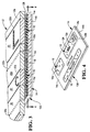
- Fig. 4 is an isometric view of the front side of the liner illustrated in Fig. 3 and taken along line 4-4.
- Fig. 5 is an isometric view of the front side of a liner in accordance with an embodiment of the present invention.
-
- Illustrated in Fig. 5 is a
liner 14 in accordance with the present invention having afront side 14a and aback side 14b.Front side 14a as a high adhesion surface capable of having an adhesive bonded thereto.Print 124 is positioned onfront surface 14a and is covered byrelease layer 16, preferably comprised of silicone, having alow adhesion surface 16a. An opaque inkreceptive layer 100 is positioned on theback side 14b ofliner 14. Theliner 14 andrelease layer 16 can be comprised of materials conventionally used in the art. The opaque ink receptive layer can be prepared from conventional pigmented varnishes. Water based white pigmented varnish is preferred, however, all colors are suitable, provided the density of the layer formed is sufficiently high to prevent the image on the other side of the liner from showing through. - While distortion of the image on
back side 14b ofliner 14 is of concern, the opaque ink receptive layer will also prevent distortion of the printed image which appears under the release layer. - The liners of this invention can be employed in the label sheets and form/label combinations of this invention described more particularly below.
- Illustrated in Figs. 1 and 2 is a label sheet or
laminate 10 in accordance with an exemplary embodiment of the present invention.Label sheet 10 includes anoverlay 12 having afront side 12a and aback side 12b. - The overlay is laminated to an
underlying release liner 14 which includes afront side 14a which faces theoverlay back side 12b, and aback side 14b. Theoverlay 12 is illustrated in sectional view in Fig. 3 laminated to theliner 14, with theliner 14 being shown in isolation in Fig. 4. - In accordance with the present invention, the
liner 14 illustrated in the exemplary embodiment in Fig. 4 includes both a relativelylow adhesion surface 16a formed, for example, by applyingrelease layer 16 to a selected portion of theliner front 14a, and a relativelyhigh adhesion surface 14c which may simply be the remaining, exposed rim or border portion of theliner front side 14a after application of the silicone or a special coating. Theliner 14 may be made of any suitable material such as paper, for example, which can be locally coated with therelease layer 16 as described in co-pending application Serial number 09/114,434, filed July 3, 1998. Opaque inkreceptive layer 100 is deposited onliner back side 14b but can be selectively deposited over portions which are aligned withrelease layer 16 by conventional flexographic printing techniques. Figs. 1 and 2 illustrate a portion of the opaque inkreceptive layer 100. Fig. 2 shows the opaque ink receptive layer with printedimage 24 thereon. Such print is preferably text of variable information applied by conventional printers such as laser, ink jet, impact and thermal transfer printers. - As shown in Figs. 2 and 3, an adhesive 18 is used to bond together
overlay 12 andliner 14. Theadhesive 18 is permanently bonded to theoverlay back side 12b and covers the entireliner front side 14a, and may have any conventional composition to form a weak bond over thelow adhesion surface 16a and a substantially permanent bond over thehigh adhesion surface 14c. In this way, theoverlay 12 is intimately bonded to theliner 14 over the liner'sentire front surface 14a except at the selectedlow adhesion surfaces 16a. This prevents the unintended separation of the overlay from the liner athigh adhesion surface 14c while allowing peeling separation of the overlay at the local regions of thelow adhesion surfaces 16a. - As shown in Figs. 1 and 2, the
overlay 12 may include one or more decals orlabels 20 having any suitable configuration or shape. The overlay may include one label laminated over theentire liner 14, or a plurality of individual labels either directly adjoining each other or separated by a remaininglabel border 20a. The individual labels ordecals 20 may be blank, or printed with numerals, letters, or graphics. - Referring again to Fig. 4, the
low adhesion surface 16a is defined by a patch or spot ofrelease layer 16, preferably of silicone, which generally matches the corresponding configurations of the individual labels such as the rectangles illustrated.High adhesion surface 14c surrounds theseveral spots 16a along the entire perimeters thereof. In this configuration, theliner 14 includes a plurality of thespots 16a which correspond with therespective labels 20 for allowing individual removal or peeling of the labels. As shown in Fig. 3, thelabel border 20a is strongly or permanently bonded to the high adhesion surface defining theliner border 14c. - As shown in Figs. 1 and 2, the
overlay 12 may include one or more cleaved separation joints, designated by the prefix 22, which may be conveniently used for separating the overlay. A first form of the separation joint is a conventional die-cut 22a which surrounds theindividual labels 20 along the perimeters thereof in a substantially continuous cut for allowing easy removal of the individual labels from the top ofliner 14. - As shown in Fig. 3, the die-
cuts 22a are preferably disposed atop therespective silicone spots 16 closely adjoining theliner border 14c. In this way,individual labels 20 may be peeled away from the liner as illustrated by the partially removed label B in Fig. 1 which separates along the die-cut 22a, with the surroundinglabel border 20a remaining securely bonded to theunderlying liner 14. This prevents separation of thelabel border 20a and eliminates the problem of exposed adhesive therefrom which could otherwise jam a laser printer for example. Furthermore, the secure bonding of thelabel border 20a to the underlying liner prevents squeeze out of the adhesive when passed through the hot fusion rollers in the laser printer. - As initially shown in Figs. 4 and 5, the
liner 14 also includes inked printing 124 in any form such as letters, numerals, and graphics atop theliner front 14a underrelease layer 16 and on the opaque inkreceptive layer 100. The release layers 16 are applied in an extremely thin layer and preferably have a clear or transparent composition for viewing the printing underneath. In view of the manufacturing process described in the co-pending application, printing atop theliner front 14a may now be accomplished prior to the application of the silicon spots 16. It is possible to provide printing under therelease layer 16 according to the procedures described in co-pending U.S. patent application Serial number 09/114,434, filed July 3, 1998. - In the embodiments illustrated in Figs. 1 and 2, the
overlay 12 and theliner 14 includeprinting 24 on theoverlay front side 12a, theliner front side 14a and the opaque inkreceptive layer 100. The printing onliner front side 14a becomes visible upon removal of the individual labels and may provide any useful information or promotions thereunder. Since theliner front 14a and back 14b, coated withink reception layer 100, are available for printing, compression of theentire label sheet 10 may be affected to contain the same amount of information in a reduced size. This reduces both the amount of material required in manufacturing thelabel sheet 10 as well as reducing its cost. - The printing under the
release layer 16 is extremely difficult to modify because it is protected by the overlying silicone. This printing is therefore secure from adulteration and may be used for various security purposes not otherwise available in conventional label sheets. Furthermore, the printing below therelease layer 16 is also protected from chemical and mechanical degradation or attack and substantially increases the longevity of the printing thereunder. - As shown in Figs. 1 and 2, a second form of the separation joint, which is optional, may include a plurality of perforations or micro-perforations 22b which are disposed linearly across the
label border 20a, and extend through both theoverlay 12 and theliner 14, and through the adhesive. - As shown in more detail in Fig. 3, the
optional perforations 22b are disposed atop the high adhesion surface of theliner border 14c in a path straddling the perforations to define a skip devoid of the silicone. This allows the label and liner to be torn along the tear. The strong adhesive bond along theoptional perforations 22b maintains the integrity of the label/liner joint while permitting the separation along the perforations. This also prevents the inadvertent exposure of adhesive at the torn edges which could inadvertently attach to other papers. - As shown in Figs. 1 and 2, the
overlay 12 may also include aform 26 in the exemplary configuration of the paper sheet extending integrally from thelabel border 20a to providing a form/label sheet combination.Liner 14 underlies solely the labels and border and not theform 26. In a preferred embodiment, theentire overlay 12 is a single sheet of paper having portions thereof defining theindividual labels 20, thelabel border 20a, and theform 26. Theform 26 may have any suitable configuration and may be blank or printed with various information as desired. - Also, if desired, the overlay may additionally include a third form of separation having a plurality of
optional perforations 22c disposed linearly across theform 26 adjacent thelabel border 20a as illustrated in Figs. 1 and 2. As shown in Fig. 3, theoptional form perforations 22c extend solely through theform 26 since theliner 14 terminates short thereof for allowing theform 26 to be separated from the labels and rim as desired. -
Overlay 12 is preferably a base sheet conventionally used in business forms and is typically a commercially available paper, but can include specialty papers and other cellulosic material such as cardboard or synthetic polymer materials. This includes individual paper sheets as well as continuous paper rolls and continuous paper fanfolds or similar continuous folding arrangements for paper. The paper can also be part of a multi-page form. The paper can be coated or uncoated; however, thefront face 12a must be suitable for printing andrear face 12b must be suitable for adhesion of an adhesive, preferably a pressure-sensitive adhesive. Theoverlay 12 is preferably sufficiently thick to provide strength such that labels can be cut and removed in one piece and printing can be performed onfront face 12a. -
Adhesive 18 can be a conventional pressure-sensitive adhesive used for labels. These include adhesives based on silicone resins, ethyl vinyl acetate copolymers, polyurethanes, polychloroprenes, polybutadienes, butadiene acrylonitrile rubbers, natural rubbers, styrene butadiene rubbers, acrylics, polyisobutylenes, butyl rubbers, higher polyvinyl alkyl ethers, S-B-S block copolymers, polyacrylate esters, vinyl ethers, styrene-isoprene butadiene acrylonitrile polymers. Preferred pressure-sensitive adhesives include hot melt pressure-sensitive adhesives. The pressure sensitive adhesive can be U.V. curable where desired. Effective hot-melt, silicone resin-based, pressure-sensitive adhesives are described in U.S. Patent 5,482,988. Solvent-based pressure-sensitive adhesives, as well as water-borne adhesives, are suitable as well. Suitable solvent-based silicon resin, pressure-sensitive adhesives include those described in U.S. Patent Nos. 4,460,371 and 5,100,976. U.S. Patent 5,489,624 describes suitable hydrophilic polyethylene oxide-based pressure-sensitive adhesives. U.S. Patent 4,647,504 describes suitable adhesive dispersions based on methylacrylate, styrene and methacrylate polymers. U.S. Patent 5,512,612 describes suitable water dispersible, poly(alkoxyalkyl)acrylate polymers and U.S. Patent 5,716,701 describes suitable acrylic copolymer emulsions. - The amount of the pressure-sensitive adhesive employed (coat weight) is preferably consistent with that employed in conventional labels. The viscosity of the adhesive also preferably conforms to conventional adhesives used in labels so that adhesive does not leak through the die cut or perforations.
-
Release layer 16 can comprise a solid silicone layer that is a U.V. cured or electron beam cured and is preferably a cationically U.V. cured or electron beam cured silicon resin. - The
labels 20 are defined withinoverlay 12 by either a die cut or perforation within the base sheet to enable easy removal. Perforations can be accomplished either before or after lamination with theliner 14. Where the labels are die cut before lamination, means for securing them must be provided.Overlay 12 may include more than one label defined by a die cut or perforation. - The
single label sheet 10 disclosed above combines various improvements thereof for clarity of presentation. - The liners, label sheets and forms/label combinations of this invention can be prepared using conventional equipment for printing
images 124, applying release layers 16, applyingadhesives 18, laminating overlays 12 andliners 14, and cleaving these laminations to formdie cuts 22a andperforations - From the foregoing description, one skilled in the art can easily ascertain the essential characteristics of this invention and, without departing from the spirit and scope thereof, can make various changes and modifications of the invention to adapt it to various usages and conditions.
Claims (10)
Applications Claiming Priority (2)
| Application Number | Priority Date | Filing Date | Title |
|---|---|---|---|
| US343995 | 1999-06-30 | ||
| US09/343,995 US6331018B1 (en) | 1999-06-30 | 1999-06-30 | Label sheet |
Publications (3)
| Publication Number | Publication Date |
|---|---|
| EP1065643A2 true EP1065643A2 (en) | 2001-01-03 |
| EP1065643A3 EP1065643A3 (en) | 2001-05-09 |
| EP1065643B1 EP1065643B1 (en) | 2007-11-28 |
Family
ID=23348580
Family Applications (1)
| Application Number | Title | Priority Date | Filing Date |
|---|---|---|---|
| EP00304742A Expired - Lifetime EP1065643B1 (en) | 1999-06-30 | 2000-06-05 | Label sheet |
Country Status (3)
| Country | Link |
|---|---|
| US (1) | US6331018B1 (en) |
| EP (1) | EP1065643B1 (en) |
| DE (1) | DE60037223T2 (en) |
Cited By (1)
| Publication number | Priority date | Publication date | Assignee | Title |
|---|---|---|---|---|
| EP3057080A3 (en) * | 2015-02-12 | 2016-10-26 | Sanford, L.P. | Sheet labels |
Families Citing this family (70)
| Publication number | Priority date | Publication date | Assignee | Title |
|---|---|---|---|---|
| US6274236B1 (en) * | 1995-06-12 | 2001-08-14 | National Label Company | Labels and method of making same |
| US6613410B1 (en) | 1999-09-23 | 2003-09-02 | National Label Company | Extended wrap label |
| US7017293B2 (en) | 2002-09-27 | 2006-03-28 | Laser Band, Llc | Wristband/cinch with label assembly business form and method |
| US7047682B2 (en) * | 2002-09-27 | 2006-05-23 | Laser Band, Llc | Wristband/label assembly business form and method |
| US7222448B2 (en) * | 2002-09-27 | 2007-05-29 | Laser Band, Llc | Thermal wristband/cinch with inboard label assembly business form and method |
| US7017294B2 (en) * | 2002-09-27 | 2006-03-28 | Laser Band, Llc | Wristband/cinch with inboard label assembly business form and method |
| US7386949B2 (en) * | 1997-10-14 | 2008-06-17 | Laser Band, Llc | Special precautions self-laminating wristband business form and method |
| US6510634B1 (en) | 1997-10-14 | 2003-01-28 | Laser Band, Llc | Multiple computer generated multi-web moisture proof identification bracelets on a single form with window |
| US6991259B2 (en) * | 1997-12-02 | 2006-01-31 | Strata-Tac, Inc. | Apparatus and method for improved business form with integrated card |
| US6770345B2 (en) * | 1999-09-23 | 2004-08-03 | National Label Company | Extended wrap label and method of making same |
| US6749230B1 (en) * | 2000-05-18 | 2004-06-15 | Charles L. Casagrande | Business form with imaging compatible punch-out card and method |
| DE60139935D1 (en) | 2000-06-02 | 2009-10-29 | Avery Dennison Corp | BUSINESS CARD CONSTRUCTION AND METHOD FOR MANUFACTURING THIS |
| JP2002254549A (en) * | 2001-03-02 | 2002-09-11 | Lintec Corp | Porous sheet laminate and water-resistant display sheet |
| US6685228B2 (en) * | 2001-06-29 | 2004-02-03 | Laser Band, Llc | Self-laminating strip label and method for assembling same |
| JP2005501299A (en) * | 2001-09-05 | 2005-01-13 | ポール・アンソニー・ミラー | Label with separable part |
| US7784210B2 (en) * | 2002-09-27 | 2010-08-31 | Laser Band, Llc | Alternative design thermal wristband business form |
| US7520077B2 (en) | 2004-06-17 | 2009-04-21 | Laser Band, Llc | Cushioned wristband with self-laminating identity tag |
| US7779569B2 (en) | 2002-09-27 | 2010-08-24 | Laser Band, Llc | Business form and self-laminating wristband with improved print area and single layer straps |
| US6773181B2 (en) * | 2002-11-13 | 2004-08-10 | Ward-Kraft, Inc. | Die cut sheet with applied coating carrier |
| US9856402B2 (en) | 2003-01-22 | 2018-01-02 | Ccl Lavel, Inc. | Adhesive label liner sheet modifications for retaining unneeded label sections on liner |
| US7118135B2 (en) * | 2003-02-07 | 2006-10-10 | Meadwestvaco Corporation | Embossed paper |
| US20050200119A1 (en) * | 2004-03-13 | 2005-09-15 | Vincent Ramirez | Multipurpose label sheet form |
| US7658026B2 (en) * | 2006-10-27 | 2010-02-09 | Laser Band, Llc | Wristband with snap closure and patent id label |
| US20060113788A1 (en) * | 2004-11-30 | 2006-06-01 | Laser Band, Llc. | Laser printable business form having a self laminating wristband and a self laminating strip label |
| US8067335B2 (en) | 2006-03-07 | 2011-11-29 | Ncr Corporation | Multisided thermal media combinations |
| US20070200338A1 (en) * | 2006-02-24 | 2007-08-30 | Avery Dennison Corporation | Co-planar multi-functional document |
| US7763344B2 (en) * | 2006-04-17 | 2010-07-27 | Laser Band, Llc | Business form comprising a wristband with multiple imaging areas |
| US7883018B2 (en) * | 2006-05-08 | 2011-02-08 | Laser Band, Llc | Method for making and a business form having printed bar codes on a coated substrate |
| US8424115B2 (en) | 2006-10-27 | 2013-04-23 | Laser Band, Llc | Wristband with contoured comfort sides |
| US7784209B2 (en) * | 2006-10-27 | 2010-08-31 | Laser Band, Llc | Laminate web wristband |
| US7818908B2 (en) * | 2007-04-13 | 2010-10-26 | Laser Band, Llc | Business form with durable self laminating wristband |
| US8904686B2 (en) | 2008-02-05 | 2014-12-09 | Laser Band, Llc | Continuous strip of thermal wristband/label forms |
| US8109021B2 (en) | 2008-05-06 | 2012-02-07 | Laser Band, Llc | Wrap around self laminating wristband |
| US8028450B2 (en) * | 2008-07-31 | 2011-10-04 | Typenex Medical, Llc | Recipient verification systems and methods of use including recipient identification |
| US8074389B2 (en) | 2009-05-05 | 2011-12-13 | Laser Band, Llc | Wristband with separated imaging area and cinch slot |
| US8528939B2 (en) * | 2009-09-02 | 2013-09-10 | Saxon, Inc. | Mountable coupon card assembly |
| US20120018332A1 (en) * | 2010-06-15 | 2012-01-26 | Avery Dennison Corporation | Pressure Sensitive Construction for Patient Privacy Protection and Method of Using the Same |
| USD640738S1 (en) | 2011-02-17 | 2011-06-28 | Laser Band, Llc | Business form with self laminating wristband and labels |
| US8776417B2 (en) | 2011-02-18 | 2014-07-15 | Laser Band, Llc | Business form with self laminating wristband with reduced image area |
| US8679277B2 (en) * | 2011-05-02 | 2014-03-25 | Dennis F. Reese | Napkin apparatus and method |
| US9707795B2 (en) * | 2011-11-11 | 2017-07-18 | A1 Label Inc. | System and method of manufacturing extended content labels |
| US20140014679A1 (en) * | 2012-07-11 | 2014-01-16 | Luis Gustavo Napolitano | Device and Method for Distribution of Holy Water |
| US10325525B1 (en) | 2015-06-12 | 2019-06-18 | Ward Kraft, Inc. | Combination wristband and label form |
| US11587470B1 (en) | 2015-06-12 | 2023-02-21 | Rekon, Llc | Business form and methods of making and using same |
| US11715394B1 (en) | 2015-10-29 | 2023-08-01 | Rekon, Llc | Wristband label form with uneven lamination panels |
| US11238759B1 (en) | 2015-10-29 | 2022-02-01 | Ward-Kraft, Inc. | Single ply wristband with printable coating |
| US10249221B2 (en) | 2015-10-29 | 2019-04-02 | Ward Kraft, Inc. | Combination wristband and label form |
| US11557228B1 (en) | 2015-10-29 | 2023-01-17 | Ward-Kraft, Inc. | Wristband and label form |
| US10997874B1 (en) | 2015-10-29 | 2021-05-04 | Ward-Kraft, Inc. | Combination wristband and label form |
| US11232719B1 (en) | 2019-09-04 | 2022-01-25 | Ward-Kraft, Inc. | Single ply wristband with printable coating |
| USD853481S1 (en) | 2016-10-31 | 2019-07-09 | Ward Kraft, Inc. | Combination wristband and label form |
| USD825655S1 (en) | 2016-10-31 | 2018-08-14 | Ward Kraft, Inc. | Combination wristband and label form |
| US11049420B2 (en) | 2016-11-15 | 2021-06-29 | Ccl Label, Inc. | Label sheet assembly with surface features |
| USD841087S1 (en) | 2016-11-17 | 2019-02-19 | Ccl Label, Inc. | Label sheet with a feed edge assembly |
| USD856414S1 (en) | 2018-03-01 | 2019-08-13 | Ccl Label, Inc. | Label sheet assembly with feed edge dress |
| USD893606S1 (en) | 2018-03-23 | 2020-08-18 | Ccl Label, Inc. | Name badge sheet assembly |
| USD877241S1 (en) | 2018-06-08 | 2020-03-03 | Ccl Label, Inc. | Label sheet layout assembly |
| USD910113S1 (en) | 2018-11-02 | 2021-02-09 | Ward-Kraft, Inc. | Combination wristband and label form |
| USD853483S1 (en) | 2018-11-02 | 2019-07-09 | Ward Kraft, Inc. | Combination wristband and label form |
| USD923706S1 (en) | 2019-08-01 | 2021-06-29 | Ward-Kraft, Inc. | Combination wristband and label form |
| USD988404S1 (en) | 2020-02-14 | 2023-06-06 | Rekon, Llc | Wristband label form with single strap wristbands |
| USD930742S1 (en) | 2020-02-18 | 2021-09-14 | Ward-Kraft, Inc. | Combination windowed wristband label form with extender |
| USD961675S1 (en) | 2020-02-18 | 2022-08-23 | Ward-Kraft, Inc. | Combination wristband label form with tags |
| USD941917S1 (en) | 2020-02-18 | 2022-01-25 | Ward-Kraft, Inc. | Combination wristband label form with extender |
| USD967253S1 (en) | 2020-02-26 | 2022-10-18 | Ward-Kraft, Inc. | Wristband form with extender |
| USD967254S1 (en) | 2020-03-06 | 2022-10-18 | Ward-Kraft, Inc. | Wristband form with extender |
| CA3115628A1 (en) | 2020-07-02 | 2022-01-02 | Ccl Label, Inc. | Label sheet assembly with puncture surface features |
| USD970610S1 (en) | 2021-04-13 | 2022-11-22 | Ward-Kraft, Inc. | Business form having a wristband with slots |
| USD970609S1 (en) | 2021-04-13 | 2022-11-22 | Ward-Kraft, Inc. | Combination wristband with slots and label form |
| USD970611S1 (en) | 2021-04-13 | 2022-11-22 | Ward-Kraft, Inc. | Combination wristband with slots and label form |
Citations (3)
| Publication number | Priority date | Publication date | Assignee | Title |
|---|---|---|---|---|
| GB2307897A (en) * | 1995-12-09 | 1997-06-11 | Simpson Label Co Ltd | Label having pigment bearing adhesive to provide background colour |
| US5704650A (en) * | 1992-10-15 | 1998-01-06 | The Standard Register Company | Laminated label form with removable portions |
| EP0973141A1 (en) * | 1998-07-13 | 2000-01-19 | Ncr International Inc. | Label sheet |
Family Cites Families (13)
| Publication number | Priority date | Publication date | Assignee | Title |
|---|---|---|---|---|
| US4460371A (en) | 1981-11-24 | 1984-07-17 | Dennison Manufacturing Company | Silicone pressure sensitive adhesive and uses |
| GB2168990B (en) | 1984-12-22 | 1988-07-06 | Hoechst Gosei Kk | Dispersion of solvent-suspendible pressure sensitive adhesive particles and pressure sensitive adhesive sheet utilizing the dispersion |
| US5100976A (en) | 1990-01-16 | 1992-03-31 | Dow Corning Corporation | Silicon pressure sensitive adhesive compositions |
| US5350612A (en) * | 1992-08-04 | 1994-09-27 | Beckett Corporation | Wet-strength removable coupon |
| US5489624A (en) | 1992-12-01 | 1996-02-06 | Minnesota Mining And Manufacturing Company | Hydrophilic pressure sensitive adhesives |
| US5580640A (en) | 1993-06-25 | 1996-12-03 | Ward/Kraft, Inc. | Integrated label having controlled release |
| US5328208A (en) | 1993-07-19 | 1994-07-12 | Wallace Computer Services, Inc. | Pharmacy form and method |
| US5482988A (en) | 1994-01-14 | 1996-01-09 | Dow Corning Corporation | Hot-melt silicone pressure sensitive adhesive with siloxylated polyether waxes as additives |
| US5521002A (en) * | 1994-01-18 | 1996-05-28 | Kimoto Tech Inc. | Matte type ink jet film |
| US5512612A (en) | 1994-04-04 | 1996-04-30 | Minnesota Mining And Manufacturing Company | Pressure sensitive adhesive employing a water-dispersible polymer and articles made there from |
| US5501393B2 (en) * | 1994-04-14 | 2000-04-11 | Walz Postal Solutions Inc | Mailing form |
| US5716701A (en) | 1995-04-10 | 1998-02-10 | Ashland Inc. | Pressure-sensitive adhesive compositions having improved peel force retention on flexible vinyl substrates |
| US5884944A (en) * | 1996-05-30 | 1999-03-23 | Durham; Mark P. | Systems and methods for recognizing and rewarding individual contributions |
-
1999
- 1999-06-30 US US09/343,995 patent/US6331018B1/en not_active Expired - Lifetime
-
2000
- 2000-06-05 EP EP00304742A patent/EP1065643B1/en not_active Expired - Lifetime
- 2000-06-05 DE DE60037223T patent/DE60037223T2/en not_active Expired - Lifetime
Patent Citations (3)
| Publication number | Priority date | Publication date | Assignee | Title |
|---|---|---|---|---|
| US5704650A (en) * | 1992-10-15 | 1998-01-06 | The Standard Register Company | Laminated label form with removable portions |
| GB2307897A (en) * | 1995-12-09 | 1997-06-11 | Simpson Label Co Ltd | Label having pigment bearing adhesive to provide background colour |
| EP0973141A1 (en) * | 1998-07-13 | 2000-01-19 | Ncr International Inc. | Label sheet |
Cited By (1)
| Publication number | Priority date | Publication date | Assignee | Title |
|---|---|---|---|---|
| EP3057080A3 (en) * | 2015-02-12 | 2016-10-26 | Sanford, L.P. | Sheet labels |
Also Published As
| Publication number | Publication date |
|---|---|
| EP1065643A3 (en) | 2001-05-09 |
| DE60037223T2 (en) | 2008-10-16 |
| DE60037223D1 (en) | 2008-01-10 |
| US6331018B1 (en) | 2001-12-18 |
| EP1065643B1 (en) | 2007-11-28 |
Similar Documents
| Publication | Publication Date | Title |
|---|---|---|
| EP1065643B1 (en) | Label sheet | |
| US6217078B1 (en) | Label sheet | |
| US6594933B2 (en) | Partial fold printable tab product | |
| US6071585A (en) | Printable sheet with removable label and method for producing same | |
| US4742954A (en) | Postal card | |
| US6511725B1 (en) | Stippled label sheet | |
| US20020000718A1 (en) | Apparatus and method for improved business form with integrated card | |
| EP1231585B1 (en) | Printable form with removable label and method for producing same | |
| US20080283582A1 (en) | Secret Postcard and Method of Fabricating the Same | |
| JP2009058816A (en) | Laminated label | |
| JP4464456B1 (en) | Slip sheet | |
| JP2009291945A (en) | Information concealing form | |
| JP4509359B2 (en) | Form with a pasting part | |
| JP5170618B2 (en) | Concealment sheet | |
| JPH06115281A (en) | Repeelable information sheet | |
| JP3688027B2 (en) | Pressure sensitive adhesive sheet | |
| JP6519196B2 (en) | Delivery document with booklet | |
| JP2007055208A (en) | Concealing sheet and concealing postcard | |
| US6083593A (en) | Multiple ply document assembly and production thereof | |
| JP2551656Y2 (en) | Removable pressure-sensitive adhesive postcard | |
| JP2010179600A (en) | Sheet for slip | |
| JPH1029390A (en) | Superimposed sheet with card | |
| JP6155658B2 (en) | Delivery slip | |
| JP2602530Y2 (en) | Lamination sheet | |
| EP1345767A1 (en) | Form comprising a printable material and a magnetic layer and laminates for creating such a form |
Legal Events
| Date | Code | Title | Description |
|---|---|---|---|
| PUAI | Public reference made under article 153(3) epc to a published international application that has entered the european phase |
Free format text: ORIGINAL CODE: 0009012 |
|
| AK | Designated contracting states |
Kind code of ref document: A2 Designated state(s): DE FR GB IT |
|
| AX | Request for extension of the european patent |
Free format text: AL;LT;LV;MK;RO;SI |
|
| PUAL | Search report despatched |
Free format text: ORIGINAL CODE: 0009013 |
|
| AK | Designated contracting states |
Kind code of ref document: A3 Designated state(s): AT BE CH CY DE DK ES FI FR GB GR IE IT LI LU MC NL PT SE |
|
| AX | Request for extension of the european patent |
Free format text: AL;LT;LV;MK;RO;SI |
|
| 17P | Request for examination filed |
Effective date: 20011109 |
|
| AKX | Designation fees paid |
Free format text: DE FR GB IT |
|
| GRAP | Despatch of communication of intention to grant a patent |
Free format text: ORIGINAL CODE: EPIDOSNIGR1 |
|
| RIN1 | Information on inventor provided before grant (corrected) |
Inventor name: FINSTER, WAYNE D. Inventor name: ROTH, JOSEPH D. |
|
| GRAS | Grant fee paid |
Free format text: ORIGINAL CODE: EPIDOSNIGR3 |
|
| GRAA | (expected) grant |
Free format text: ORIGINAL CODE: 0009210 |
|
| AK | Designated contracting states |
Kind code of ref document: B1 Designated state(s): DE FR GB IT |
|
| REG | Reference to a national code |
Ref country code: GB Ref legal event code: FG4D |
|
| REF | Corresponds to: |
Ref document number: 60037223 Country of ref document: DE Date of ref document: 20080110 Kind code of ref document: P |
|
| ET | Fr: translation filed | ||
| PLBE | No opposition filed within time limit |
Free format text: ORIGINAL CODE: 0009261 |
|
| STAA | Information on the status of an ep patent application or granted ep patent |
Free format text: STATUS: NO OPPOSITION FILED WITHIN TIME LIMIT |
|
| 26N | No opposition filed |
Effective date: 20080829 |
|
| REG | Reference to a national code |
Ref country code: GB Ref legal event code: 746 Effective date: 20090416 |
|
| REG | Reference to a national code |
Ref country code: FR Ref legal event code: PLFP Year of fee payment: 17 |
|
| REG | Reference to a national code |
Ref country code: DE Ref legal event code: R082 Ref document number: 60037223 Country of ref document: DE Representative=s name: V. BEZOLD & PARTNER PATENTANWAELTE - PARTG MBB, DE Ref country code: DE Ref legal event code: R081 Ref document number: 60037223 Country of ref document: DE Owner name: ICONEX LLC, DULUTH, US Free format text: FORMER OWNER: NCR INTERNATIONAL, INC., DAYTON, OHIO, US |
|
| PGFP | Annual fee paid to national office [announced via postgrant information from national office to epo] |
Ref country code: IT Payment date: 20160726 Year of fee payment: 17 Ref country code: GB Payment date: 20160801 Year of fee payment: 17 Ref country code: DE Payment date: 20160726 Year of fee payment: 17 |
|
| PGFP | Annual fee paid to national office [announced via postgrant information from national office to epo] |
Ref country code: FR Payment date: 20160802 Year of fee payment: 17 |
|
| REG | Reference to a national code |
Ref country code: GB Ref legal event code: 732E Free format text: REGISTERED BETWEEN 20170216 AND 20170222 |
|
| REG | Reference to a national code |
Ref country code: DE Ref legal event code: R119 Ref document number: 60037223 Country of ref document: DE |
|
| GBPC | Gb: european patent ceased through non-payment of renewal fee |
Effective date: 20170605 |
|
| REG | Reference to a national code |
Ref country code: FR Ref legal event code: ST Effective date: 20180228 |
|
| PG25 | Lapsed in a contracting state [announced via postgrant information from national office to epo] |
Ref country code: GB Free format text: LAPSE BECAUSE OF NON-PAYMENT OF DUE FEES Effective date: 20170605 Ref country code: DE Free format text: LAPSE BECAUSE OF NON-PAYMENT OF DUE FEES Effective date: 20180103 |
|
| PG25 | Lapsed in a contracting state [announced via postgrant information from national office to epo] |
Ref country code: IT Free format text: LAPSE BECAUSE OF NON-PAYMENT OF DUE FEES Effective date: 20170605 Ref country code: FR Free format text: LAPSE BECAUSE OF NON-PAYMENT OF DUE FEES Effective date: 20170630 |