EP1069009A1 - Friction coupling, especially for a torque limiter in a seat belt retractor - Google Patents
Friction coupling, especially for a torque limiter in a seat belt retractor Download PDFInfo
- Publication number
- EP1069009A1 EP1069009A1 EP00113188A EP00113188A EP1069009A1 EP 1069009 A1 EP1069009 A1 EP 1069009A1 EP 00113188 A EP00113188 A EP 00113188A EP 00113188 A EP00113188 A EP 00113188A EP 1069009 A1 EP1069009 A1 EP 1069009A1
- Authority
- EP
- European Patent Office
- Prior art keywords
- belt
- coupling
- formations
- friction
- friction clutch
- Prior art date
- Legal status (The legal status is an assumption and is not a legal conclusion. Google has not performed a legal analysis and makes no representation as to the accuracy of the status listed.)
- Granted
Links
Images

Classifications
-
- B—PERFORMING OPERATIONS; TRANSPORTING
- B60—VEHICLES IN GENERAL
- B60R—VEHICLES, VEHICLE FITTINGS, OR VEHICLE PARTS, NOT OTHERWISE PROVIDED FOR
- B60R22/00—Safety belts or body harnesses in vehicles
- B60R22/34—Belt retractors, e.g. reels
- B60R22/341—Belt retractors, e.g. reels comprising energy-absorbing means
- B60R22/3413—Belt retractors, e.g. reels comprising energy-absorbing means operating between belt reel and retractor frame
-
- F—MECHANICAL ENGINEERING; LIGHTING; HEATING; WEAPONS; BLASTING
- F16—ENGINEERING ELEMENTS AND UNITS; GENERAL MEASURES FOR PRODUCING AND MAINTAINING EFFECTIVE FUNCTIONING OF MACHINES OR INSTALLATIONS; THERMAL INSULATION IN GENERAL
- F16D—COUPLINGS FOR TRANSMITTING ROTATION; CLUTCHES; BRAKES
- F16D7/00—Slip couplings, e.g. slipping on overload, for absorbing shock
- F16D7/02—Slip couplings, e.g. slipping on overload, for absorbing shock of the friction type
- F16D7/021—Slip couplings, e.g. slipping on overload, for absorbing shock of the friction type with radially applied torque-limiting friction surfaces
-
- B—PERFORMING OPERATIONS; TRANSPORTING
- B60—VEHICLES IN GENERAL
- B60R—VEHICLES, VEHICLE FITTINGS, OR VEHICLE PARTS, NOT OTHERWISE PROVIDED FOR
- B60R22/00—Safety belts or body harnesses in vehicles
- B60R22/28—Safety belts or body harnesses in vehicles incorporating energy-absorbing devices
- B60R2022/285—Safety belts or body harnesses in vehicles incorporating energy-absorbing devices using friction surfaces
-
- B—PERFORMING OPERATIONS; TRANSPORTING
- B60—VEHICLES IN GENERAL
- B60R—VEHICLES, VEHICLE FITTINGS, OR VEHICLE PARTS, NOT OTHERWISE PROVIDED FOR
- B60R22/00—Safety belts or body harnesses in vehicles
- B60R22/34—Belt retractors, e.g. reels
- B60R22/46—Reels with means to tension the belt in an emergency by forced winding up
- B60R22/4676—Reels with means to tension the belt in an emergency by forced winding up comprising energy-absorbing means operating between belt reel and retractor frame
Definitions
- the invention relates to a friction clutch, in particular for Torque limitation in a belt retractor, with two each other opposite coupling surfaces and one between the coupling surfaces arranged friction element.
- the invention also relates to a Belt retractor with a belt reel rotatably mounted in a frame and a locking mechanism for the belt reel with at least one with the belt reel connected locking disc and one in the power flow path Torque limiting element arranged between the belt reel and the locking disk.
- Known friction clutches have a metal disk as the friction element on, which is arranged between two clutch plates and on both sides is provided with a clutch lining.
- the clutch lining provides On the one hand, a high frictional force to the clutch plates is safe and is on the other hand, designed to withstand the pressure and temperature loads has grown in the company.
- the friction element is therefore always made up of several Parts composed of different materials. To the required Contact pressure and thus to ensure sufficient friction, the clutch plates and the friction element with the help compressed by a separate spring.
- belt force limitation is thereby achieved achieved that in the power flow path between the belt spool and Locking disc is arranged a torsion bar, which is when exceeded a predetermined torque twisted and plastic deformed.
- a controlled torque limit is only here once and in one direction possible.
- the invention aims to provide a friction clutch and a belt retractor Torque limitation can be created in two directions work force-limiting and at the same time simply constructed and inexpensive are producible.
- a friction clutch in particular for Torque limitation in a belt retractor, with two opposite one another Coupling surfaces and one between the coupling surfaces arranged friction element is provided, in which the friction element as flat spring component is formed with formations, the Formations at least partially on one of the coupling surfaces issue.
- Such a friction clutch is particularly simple and inexpensive producible, since the required contact pressure between Friction element and clutch surfaces applied by the friction element itself is because this is designed as a spring component. A separate Pressure spring can thus be omitted.
- the friction element can, for example produced in a simple manner as a sheet metal stamping element at low cost become.
- the torque that can be transmitted through the friction clutch is substantially determined by the spring force of the spring component.
- the formations have in one Direction parallel to the coupling surfaces a circular section Cross section on. With a circular cross-section good spring properties are achieved. In tangential Direction to the circular section-shaped cross section of the formations the transferable friction force is also independent of direction.
- the spring component is advantageously in the form of a wavy band educated. Such a wavy band is simple and is suitable for arrangement between concentric coupling surfaces. Both the formations partially in contact with the first coupling surface as well as those partially in contact with the second coupling surface Formations of the spring component then have a circular section Cross-section. These measures also allow that the friction element consists of a single component.
- the spring component as a cylinder is designed with resilient shapes.
- Friction element made of a single component and is between two concentric Coupling surfaces particularly easy to assemble because of the Cylinder has a certain inherent stability and so easily between the coupling surfaces can be pressed.
- the spring component designed as a plate with resilient formations.
- the Spring component also consists of a single component and can in can be produced in a particularly simple manner as a stamped sheet metal part.
- a belt retractor with one in one Frame rotatably mounted belt reel, a locking mechanism for the Belt reel with at least one locking disk connected to the belt reel and one in the power flow path between the belt reel and the Locking disk arranged torque limiting element provided at which the torque limiting element as a friction clutch according to the invention is trained.
- a belt retractor acts in two directions force limiting, since the friction clutch torque in two directions limited. This means that peak belt force values can be achieved both when the belt reel is blocked when the vehicle or belt is sensitive, and when Insert one that engages the belt spool via the friction clutch Belt tensioners can be avoided.
- the belt retractor according to the invention can also be used after one Torque limit can be reused.
- the first coupling surface is on a the belt reel rotatably connected first clutch plate and the second coupling surface on a rotationally fixed with the locking disc connected second clutch plate provided, and between the Coupling plates is a plate with resilient shapes.
- the first coupling surface through an outer surface of an extension of a with the belt reel rotationally connected belt reel axis and the second Coupling surface through an inner surface of a rotatable with the Locking disk connected hollow cylinder is formed.
- Such a Belt retractor requires only one to realize the friction clutch low construction costs, since only the change of existing ones Components, namely the belt reel axis and the locking disc, and that Spring component are required.
- the belt spool axis only has to one, for example, extending outside the frame Extension must be provided, and on the lock washer must for Belt reel axis concentric hollow cylinder are attached.
- the Spring component is then on the extension of the belt reel axis and in inserted the hollow cylinder of the locking disc.
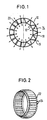
- FIG. 1 shows two concentrically mutually arranged coupling surfaces 10 and 12. On the right Side of Figure 1 is between these coupling surfaces 10 and 12 band-shaped spring component 14 arranged.
- the band-shaped spring component 14 has formations that are partially on the first coupling surface 10 adjacent first sections 16 and partially on the second coupling surface Form 12 adjacent second sections 18. Both the first sections 16 and also second sections 18 point in FIG a direction parallel to the coupling surfaces 10 and 12 a circular section Cross section on. Through the circular section Formations of the spring component 14 takes the form of a wavy band.
- the spring component 14 is between the coupling surfaces 10 and 12 pressed so that by the spring action of Spring component 14, the first sections 16 a force on the coupling surface 10 and the second sections 18 a force on the coupling surface Exercise 12. Those exerted on the coupling surfaces 10 and 12 Forces are symbolized by arrows in FIG. 1.
- the spring action of the spring component 14 between the coupling surfaces 10 and 12 is symbolized in the left part of FIG. 1 by coil springs 20, which are arranged between the coupling surfaces 10 and 12 and on they exert a force.
- Each shaft of the spring component 14 behaves like a spring 20, the force of which is proportional to the elastic range Spring constants and for deflecting the spring.
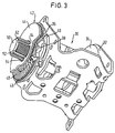
- a spring component 22 which as Cylinder with resilient formations 24 is formed.
- the formations 24 have an elongated shape and a plurality of formations 24 are adjacent to each other with their respective long sides Circumference of the cylinder 22 arranged around.
- the cylinder 22 has one certain intrinsic stability so that it is easily concentric between two Coupling surfaces can be pressed.
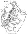
- FIG. 3 shows a first embodiment of an inventive Belt retractor 30.
- the belt retractor 30 has a frame 32, one in the frame 32 mounted belt reel 34 and a locking mechanism for the belt reel 34.
- the blocking mechanism consists of a Locking disk 36 with locking teeth 38.
- a pawl 40 by a conventional control mechanism that is sensitive to the vehicle and the seat belt, which is not shown, in the locking teeth 38th be controlled.
- the belt retractor 30 is used to limit the belt force provided with a friction clutch 42 which in the power flow between the Belt reel 34 and the locking disk 36 is arranged.
- the friction clutch 42 consists of the locking disk 36, a clutch plate 44 and one arranged between the locking disk 36 and the clutch plate 44 Spring plate 46.
- the spring plate 46 is designed as a stamped sheet metal part and has resilient formations 48 which are circular in two rows are arranged around the center of the circular plate 46.
- a Belt reel axis 50 is fixedly connected to the belt reel 34 and extends through the frame 32, the locking teeth 38, the locking disc 36, the spring plate 46 and the clutch plate 44 therethrough. While the locking disc 36 is rotatably mounted on the belt reel axis 50 is, the clutch plate 44 is rotationally fixed but longitudinally displaceable attached to the belt reel axis 50.
- the belt spool axis 50 a plurality of longitudinal grooves 52, in the lugs 54 of the clutch plate 44th intervention.
- the mother 56 is tightened more or less strongly.
- the formations 48 of the Spring plate 46 one in a direction parallel to the coupling surfaces have circular cross-section.
- the formations 48 thereby have a good spring action, and the friction clutch 42 can limit torque in two directions.
- the single ones Formations 48 of the spring plate 46 are formed by straight sections 58 connected with each other. During the formations 48 first sections of the spring plate 46, which on the by the frame 32 facing Surface of the clutch plate 44 formed first clutch surface the straight sections 58 form second sections, which rest on the second coupling surface, which is caused by the of the Frame 32 facing surface of the locking disk 36 is formed.
- the pawl 40 becomes vehicle or belt-sensitive controlled in the locking teeth 38 of the locking disk 36, so that the belt reel 34 is blocked relative to the frame 32 and no more webbing can be pulled off the belt reel 34.
- the friction clutch 42 must transmit a torque. Exceeds this torque to be transmitted from the friction clutch 42 predetermined value, will also be the maximum between those by the Formations 48 formed first sections and the first coupling surface or at most between those through the straight sections 58 formed second sections and the second coupling surface transferable Frictional force exceeded, so that the clutch disc 44 can rotate relative to the locking disk 36.
- FIG. 5 A second embodiment of a belt retractor according to the invention 60 is shown in FIG. 5.
- the belt retractor 60 shown in FIGS. 3 and 4 has the belt retractor 60 a frame 62, a belt reel 64, a locking disk 66 with locking teeth 68 and a pawl controllable into the locking toothing 68 70 on.
- the belt spool 64 has one fixed to the belt spool 64 connected axis, which extends beyond the frame 62 extending extension 72 has.
- the locking disk 66 is fixed with provided a hollow cylinder 74 in which the extension 72 of the Belt reel axis extends.
- One from a cylinder 76 with resilient Formations 78 existing spring component is between the extension 72 of the belt reel axis and the hollow cylinder 74 of the locking disk 66 pressed in.
- the provided in the belt retractor 60 friction clutch Torque is limited by a lateral surface of the extension 72, the cylinder 76 with resilient formations 78 and the Inner surface of the hollow cylinder 74 is formed.
- the arrangement of the friction clutch shown is the relative speed equal between the coupling surfaces over the entire coupling surfaces, so that the existing from the cylinder 76 with the formations 78 Spring component is loaded evenly everywhere.
Abstract
Description
Die Erfindung betrifft eine Reibkupplung, insbesondere zur Drehmomentbegrenzung in einem Gurtaufroller, mit zwei einander gegenüberliegenden Kupplungsflächen und einem zwischen den Kupplungsflächen angeordneten Reibelement. Die Erfindung betrifft auch einen Gurtaufroller mit einer in einem Rahmen drehbar gelagerten Gurtspule und einem Blockiermechanismus für die Gurtspule mit wenigstens einer mit der Gurtspule verbundenen Sperrscheibe und einem im Kraftflußweg zwischen der Gurtspule und der Sperrscheibe angeordneten Drehmomentbegrenzungselement.The invention relates to a friction clutch, in particular for Torque limitation in a belt retractor, with two each other opposite coupling surfaces and one between the coupling surfaces arranged friction element. The invention also relates to a Belt retractor with a belt reel rotatably mounted in a frame and a locking mechanism for the belt reel with at least one with the belt reel connected locking disc and one in the power flow path Torque limiting element arranged between the belt reel and the locking disk.
Bekannte Reibkupplungen weisen als Reibelement eine Metallscheibe auf, die zwischen zwei Kupplungsplatten angeordnet ist und beidseitig mit einem Kupplungsbelag versehen ist. Der Kupplungsbelag stellt einerseits eine hohe Reibkraft zu den Kupplungsplatten sicher und ist andererseits so ausgelegt, daß er den Druck- und Temperaturbelastungen im Betrieb gewachsen ist. Das Reibelement ist damit stets aus mehreren Teilen aus unterschiedlichem Material zusammengesetzt. Um den erforderlichen Anpreßdruck und damit eine ausreichende Reibkraft sicherzustellen, werden die Kupplungsplatten und das Reibelement mit Hilfe einer separaten Feder zusammengedrückt.Known friction clutches have a metal disk as the friction element on, which is arranged between two clutch plates and on both sides is provided with a clutch lining. The clutch lining provides On the one hand, a high frictional force to the clutch plates is safe and is on the other hand, designed to withstand the pressure and temperature loads has grown in the company. The friction element is therefore always made up of several Parts composed of different materials. To the required Contact pressure and thus to ensure sufficient friction, the clutch plates and the friction element with the help compressed by a separate spring.
Bei bekannten Gurtaufrollern wird eine Gurtkraftbegrenzung dadurch erreicht, daß im Kraftflußweg zwischen der Gurtspule und der Sperrscheibe ein Torsionsstab angeordnet ist, der sich bei Überschreitung eines vorbestimmten Drehmoments verdreht und dabei plastisch verformt. Eine kontrollierte Drehmomentbegrenzung ist hierbei nur einmal und in einer Richtung möglich.In known belt retractors, belt force limitation is thereby achieved achieved that in the power flow path between the belt spool and Locking disc is arranged a torsion bar, which is when exceeded a predetermined torque twisted and plastic deformed. A controlled torque limit is only here once and in one direction possible.
Mit der Erfindung soll eine Reibkupplung und ein Gurtaufroller mit Drehmomentbegrenzung geschaffen werden, die in zwei Richtungen kraftbegrenzend arbeiten und dabei einfach aufgebaut und kostengünstig herstellbar sind.The invention aims to provide a friction clutch and a belt retractor Torque limitation can be created in two directions work force-limiting and at the same time simply constructed and inexpensive are producible.
Erfindungsgemäß ist hierzu eine Reibkupplung, insbesondere zur Drehmomentbegrenzung in einem Gurtaufroller, mit zwei einander gegenüberliegenden Kupplungsflächen und einem zwischen den Kupplungsflächen angeordneten Reibelement vorgesehen, bei der das Reibelement als flächiges Federbauteil mit Ausformungen ausgebildet ist, wobei die Ausformungen wenigstens teilweise an einer der Kupplungsflächen anliegen. Eine solche Reibkupplung ist besonders einfach und kostengünstig herstellbar, da die erforderliche Anpreßkraft zwischen Reibelement und Kupplungsflächen von dem Reibelement selbst aufgebracht wird, da dieses als Federbauteil ausgeführt ist. Eine separate Anpreßfeder kann damit entfallen. Das Reibelement kann beispielsweise in einfacher Weise als Blechprägeelement mit geringen Kosten hergestellt werden. Das durch die Reibkupplung übertragbare Drehmoment ist wesentlich durch die Federkraft des Federbauteils mitbestimmt.According to the invention there is a friction clutch, in particular for Torque limitation in a belt retractor, with two opposite one another Coupling surfaces and one between the coupling surfaces arranged friction element is provided, in which the friction element as flat spring component is formed with formations, the Formations at least partially on one of the coupling surfaces issue. Such a friction clutch is particularly simple and inexpensive producible, since the required contact pressure between Friction element and clutch surfaces applied by the friction element itself is because this is designed as a spring component. A separate Pressure spring can thus be omitted. The friction element can, for example produced in a simple manner as a sheet metal stamping element at low cost become. The torque that can be transmitted through the friction clutch is substantially determined by the spring force of the spring component.
In Weiterbildung der Erfindung weisen die Ausformungen in einer Richtung parallel zu den Kupplungsflächen einen kreisabschnittsförmigen Querschnitt auf. Mit einem kreisabschnittsförmigen Querschnitt werden gute Federeigenschaften erreicht. In tangentialer Richtung zu dem kreisabschnittsförmigen Querschnitt der Ausformungen ist die übertragbare Reibkraft darüber hinaus richtungsunabhängig.In a development of the invention, the formations have in one Direction parallel to the coupling surfaces a circular section Cross section on. With a circular cross-section good spring properties are achieved. In tangential Direction to the circular section-shaped cross section of the formations the transferable friction force is also independent of direction.
Vorteilhafterweise ist das Federbauteil als wellenförmiges Band ausgebildet. Ein solches wellenförmiges Band ist einfach aufgebaut und eignet sich zur Anordnung zwischen konzentrischen Kupplungsflächen. Sowohl die teilweise an der ersten Kupplungsfläche anliegenden Ausformungen als auch die teilweise an der zweiten Kupplungsfläche anliegenden Ausformungen des Federbauteils haben dann einen kreisabschnittsförmigen Querschnitt. Diese Maßnahmen erlauben es auch, daß das Reibelement aus einem einzigen Bauteil besteht.The spring component is advantageously in the form of a wavy band educated. Such a wavy band is simple and is suitable for arrangement between concentric coupling surfaces. Both the formations partially in contact with the first coupling surface as well as those partially in contact with the second coupling surface Formations of the spring component then have a circular section Cross-section. These measures also allow that the friction element consists of a single component.
Ebenfalls vorteilhaft ist es, wenn das Federbauteil als Zylinder mit federnden Ausformungen ausgebildet ist. Auch hier besteht das Reibelement aus einem einzigen Bauteil und ist zwischen zwei konzentrischen Kupplungsflächen besonders einfach montierbar, da der Zylinder eine gewisse Eigenstabilität aufweist und so leicht zwischen die Kupplungsflächen eingepreßt werden kann.It is also advantageous if the spring component as a cylinder is designed with resilient shapes. This also exists here Friction element made of a single component and is between two concentric Coupling surfaces particularly easy to assemble because of the Cylinder has a certain inherent stability and so easily between the coupling surfaces can be pressed.
Bei einer weiteren vorteilhaften Ausbildung ist das Federbauteil als Platte mit federnden Ausformungen ausgebildet. Eine solche Ausführung erlaubt die Anordnung zwischen zwei Kupplungsplatten. Das Federbauteil besteht ebenfalls aus einem einzigen Bauteil und kann in besonders einfacher Weise als Blechprägeteil hergestellt werden.In a further advantageous embodiment, the spring component designed as a plate with resilient formations. Such an execution allows the arrangement between two clutch plates. The Spring component also consists of a single component and can in can be produced in a particularly simple manner as a stamped sheet metal part.
Gemäß der Erfindung ist auch ein Gurtaufroller mit einer in einem Rahmen drehbar gelagerten Gurtspule, einem Blockiermechanismus für die Gurtspule mit wenigstens einer mit der Gurtspule verbundenden Sperrscheibe und einem im Kraftflußweg zwischen der Gurtspule und der Sperrscheibe angeordneten Drehmomentbegrenzungselement vorgesehen, bei dem das Drehmomentbegrenzungselement als erfindungsgemäße Reibkupplung ausgebildet ist. Ein solcher Gurtaufroller wirkt in zwei Richtungen kraftbegrenzend, da die Reibkupplung das Drehmoment in zwei Richtungen begrenzt. Damit können Spitzenwerte der Gurtkraft sowohl beim fahrzeug- oder gurtbandsensitiven Blockieren der Gurtspule als auch beim Einsetzen eines über die Reibungskupplung an der Gurtspule angreifenden Gurtstraffers vermieden werden. Im Gegensatz zu konventionellen Gurtaufrollern mit Torsionsstäben als Drehmomentbegrenzungselement kann der erfindungsgemäße Gurtaufroller auch nach einer erfolgten Drehmomentbegrenzung wiederverwendet werden.According to the invention is also a belt retractor with one in one Frame rotatably mounted belt reel, a locking mechanism for the Belt reel with at least one locking disk connected to the belt reel and one in the power flow path between the belt reel and the Locking disk arranged torque limiting element provided at which the torque limiting element as a friction clutch according to the invention is trained. Such a belt retractor acts in two directions force limiting, since the friction clutch torque in two directions limited. This means that peak belt force values can be achieved both when the belt reel is blocked when the vehicle or belt is sensitive, and when Insert one that engages the belt spool via the friction clutch Belt tensioners can be avoided. Unlike conventional ones Belt retractors with torsion bars as a torque limiting element the belt retractor according to the invention can also be used after one Torque limit can be reused.
In vorteilhafter Weise ist die erste Kupplungsfläche an einer mit der Gurtspule drehfest verbundenen ersten Kupplungsplatte und die zweite Kupplungsfläche auf einer drehfest mit der Sperrscheibe verbundenen zweiten Kupplungsplatte vorgesehen, und zwischen den Kupplungsplatten ist eine Platte mit federnden Ausformungen angeordnet. Diese Maßnahmen ermöglichen eine platzsparende Ausführung des Gurtaufrollers, da die Reibkupplung flach ausgeführt ist und sich in radialer Richtung erstreckt. Die Reibkupplung kann beispielsweise außerhalb des Rahmens des Gurtaufrollers auf der Gurtspulenachse angeordnet werden.Advantageously, the first coupling surface is on a the belt reel rotatably connected first clutch plate and the second coupling surface on a rotationally fixed with the locking disc connected second clutch plate provided, and between the Coupling plates is a plate with resilient shapes. These measures enable a space-saving execution of the Belt retractor because the friction clutch is flat and in extends in the radial direction. The friction clutch can, for example outside the frame of the belt retractor on the belt reel axis to be ordered.
Eine vorteilhafte Ausführung ergibt sich auch dadurch, daß die erste Kupplungsfläche auf einer mit der Gurtspule drehfest verbundenen Zylinderfläche und die zweite Kupplungsfläche auf einer drehfest mit der Sperrscheibe verbundenen Zylinderfläche vorgesehen ist und zwischen den Kupplungsflächen ein Zylinder mit federnden Ausformungen angeornet ist. Bei einem solchen Gurtaufroller wird das Federbauteil gleichmäßig beansprucht, da zwischen den konzentrischen Kupplungsflächen überall die gleiche Relativgeschwindigkeit auftritt.An advantageous embodiment results from the fact that the first coupling surface on a non-rotatably connected to the belt reel Cylinder surface and the second clutch surface on a rotatable with the locking disk connected cylinder surface is provided and between the coupling surfaces a cylinder with resilient shapes is arranged. With such a belt retractor, the spring component evenly stressed because between the concentric coupling surfaces the same relative speed occurs everywhere.
In Weiterbildung der Erfindung ist schließlich vorgesehen, daß die erste Kupplungsfläche durch eine Mantelfläche einer Verlängerung einer mit der Gurtspule drehfest verbundenen Gurtspulenachse und die zweite Kupplungsfläche durch eine Innenfläche eines drehfest mit der Sperrscheibe verbundenen Hohlzylinders gebildet ist. Ein solcher Gurtaufroller erfordert zur Realisierung der Reibkupplung nur einen geringen Bauaufwand, da lediglich die Änderung bereits vorhandener Bauteile, nämlich der Gurtspulenachse und der Sperrscheibe, sowie das Federbauteil erforderlich sind. Die Gurtspulenachse muß lediglich mit einer, sich beispielsweise außerhalb des Rahmens erstreckenden Verlängerung versehen werden, und an der Sperrscheibe muß ein zur Gurtspulenachse konzentrischer Hohlzylinder angebracht werden. Das Federbauteil wird dann auf die Verlängerung der Gurtspulenachse und in den Hohlzylinder der Sperrscheibe eingeschoben.In a further development of the invention it is finally provided that the first coupling surface through an outer surface of an extension of a with the belt reel rotationally connected belt reel axis and the second Coupling surface through an inner surface of a rotatable with the Locking disk connected hollow cylinder is formed. Such a Belt retractor requires only one to realize the friction clutch low construction costs, since only the change of existing ones Components, namely the belt reel axis and the locking disc, and that Spring component are required. The belt spool axis only has to one, for example, extending outside the frame Extension must be provided, and on the lock washer must for Belt reel axis concentric hollow cylinder are attached. The Spring component is then on the extension of the belt reel axis and in inserted the hollow cylinder of the locking disc.
Weitere Merkmale und Vorteile der Erfindung ergeben sich aus der
folgenden Beschreibung bevorzugter Ausführungsformen der Erfindung
unter Bezugnahme auf die Zeichnung. In der Zeichnung zeigen:
Die schematische Darstellung der Figur 1 zeigt zwei konzentrisch
zueinander angeordnete Kupplungsflächen 10 und 12. Auf der rechten
Seite der Figur 1 ist zwischen diesen Kupplungsflächen 10 und 12 ein
bandförmiges Federbauteil 14 angeordnet. Das bandförmige Federbauteil
14 weist Ausformungen auf, die teilweise an der ersten Kupplungsfläche
10 anliegende erste Abschnitte 16 und teilweise an der zweiten Kupplungsfläche
12 anliegende zweite Abschnitte 18 bilden. Sowohl die
ersten Abschnitte 16 als auch die zweiten Abschnitte 18 weisen in
einer Richtung parallel zu den Kupplungsflächen 10 und 12 einen kreisabschnittsförmigen
Querschnitt auf. Durch die kreisabschnittsförmigen
Ausformungen des Federbauteils 14 nimmt dieses die Gestalt eines
wellenförmigen Bandes an. Das Federbauteil 14 ist zwischen die Kupplungsflächen
10 und 12 eingepreßt, so daß durch die Federwirkung des
Federbauteils 14 die ersten Abschnitte 16 eine Kraft auf die Kupplungsfläche
10 und die zweiten Abschnitte 18 eine Kraft auf die Kupplungsfläche
12 ausüben. Die auf die Kupplungsflächen 10 und 12 ausgeübten
Kräfte sind in der Figur 1 durch Pfeile symbolisiert. Die Federwirkung
des Federbauteils 14 zwischen den Kupplungsflächen 10 und 12
ist im linken Teil der Figur 1 durch Schraubenfedern 20 symbolisiert,
die zwischen den Kupplungsflächen 10 und 12 angeordnet sind und auf
diese eine Kraft ausüben. Jede Welle des Federbauteils 14 verhält sich
wie eine Feder 20, deren Kraft im elastischen Bereich proportional zur
Federkonstanten und zur Auslenkung der Feder ist. Die zwischen dem
Federbauteil 14 und den Kupplungsflächen 10 bzw. 12 übertragbare Reibkraft
ergibt sich aus der in der Figur 1 durch Pfeile angedeuteten
Radialkraft, die senkrecht zu den Kupplungsflächen 10 bzw. 12 ist, und
dem Reibungskoeffizienten zwischen dem Federbauteil 14 und der Kupplungsfläche
10 bzw. 12. Das durch die Reibkupplung insgesamt übertragbare
Drehmoment folgt dann aus den radialen Abmessungen der Kupplung.
Bei Überschreitung eines vorbestimmten Drehmoments erfolgt zwischen
dem Federbauteil 14 und den Kupplungsflächen 10 bzw. 12 ein Übergang
von Haftreibung zu Gleitreibung. Dadurch sinkt das übertragbare Drehmoment
ab, und die Kraft in einem beispielsweise an die Kupplungsfläche
10 angeschlossenen Gurtband wird begrenzt. Die in der Figur 1
dargestellte Reibkupplung kann das übertragene Drehmoment dabei in
zwei Richtungen, im Uhrzeigersinn und entgegen dem Uhrzeigersinn,
begrenzen.The schematic representation of FIG. 1 shows two concentrically
mutually arranged
In der Figur 2 ist ein Federbauteil 22 dargestellt, das als
Zylinder mit federnden Ausformungen 24 ausgebildet ist. Die Ausformungen
24 weisen eine längliche Form auf, und mehrere Ausformungen 24
sind mit ihrer jeweiligen Längsseite aneinander angrenzend um den
Umfang des Zylinders 22 herum angeordnet. Der Zylinder 22 weist eine
gewisse Eigenstabilität auf, so daß er leicht zwischen zwei konzentrische
Kupplungsflächen eingepreßt werden kann.In the figure 2, a
Figur 3 zeigt eine erste Ausführungsform eines erfindungsgemäßen
Gurtaufrollers 30. Der Gurtaufroller 30 weist einen Rahmen 32, eine in
dem Rahmen 32 gelagerte Gurtspule 34 und einen Blockiermechanismus für
die Gurtspule 34 auf. Der Blockiermechanismus besteht aus einer
Sperrscheibe 36 mit Sperrverzahnung 38. Zur Blockierung der Gurtspule
34 gegenüber dem Rahmen 32 kann eine Sperrklinke 40 durch einen
konventionellen, fahrzeug- und gurtbandsensitiv wirkenden Ansteuermechanismus,
der nicht dargestellt ist, in die Sperrverzahnung 38
eingesteuert werden. Zur Gurtkraftbegrenzung ist der Gurtaufroller 30
mit einer Reibkupplung 42 versehen, die im Kraftfluß zwischen der
Gurtspule 34 und der Sperrscheibe 36 angeordnet ist. Die Reibkupplung
42 besteht aus der Sperrscheibe 36, einer Kupplungsplatte 44 und einem
zwischen der Sperrscheibe 36 und der Kupplungsplatte 44 angeordneten
Federplatte 46. Die Federplatte 46 ist als Blechprägeteil ausgeführt
und weist federnde Ausformungen 48 auf, die kreisförmig in zwei Reihen
um den Mittelpunkt der kreisförmigen Platte 46 angeordnet sind. Eine
Gurtspulenachse 50 ist fest mit der Gurtspule 34 verbunden und
erstreckt sich durch den Rahmen 32, die Sperrverzahnung 38, die Sperrscheibe
36, die Federplatte 46 und die Kupplungsplatte 44 hindurch.
Während die Sperrscheibe 36 drehbar auf der Gurtspulenachse 50 gelagert
ist, ist die Kupplungsplatte 44 drehfest aber längsverschieblich
an der Gurtspulenachse 50 befestigt. Hierzu weist die Gurtspulenachse
50 mehrere Längsnuten 52 auf, in die Nasen 54 der Kupplungsplatte 44
eingreifen.Figure 3 shows a first embodiment of an
Wie in der Figur 4 zu erkennen ist, wird die Kupplungsplatte 44
mit einer auf die Gurtspulenachse 50 aufgeschraubten Mutter 56 gegen
die Federplatte 46 und die Sperrscheibe 36 vorgespannt. Je nachdem,
wie groß das durch die Reibkupplung 42 übertragbare Drehmoment sein
soll, wird die Mutter 56 mehr oder weniger stark angezogen.As can be seen in FIG. 4, the clutch plate 44
with a
In der Figur 4 ist auch zu erkennen, daß die Ausformungen 48 der
Federplatte 46 einen in einer Richtung parallel zu den Kupplungsflächen
kreisabschnittsförmigen Querschnitt aufweisen. Die Ausformungen
48 haben dadurch eine gute Federwirkung, und die Reibkupplung 42
kann in zwei Richtungen drehmomentbegrenzend wirken. Die einzelnen
Ausformungen 48 der Federplatte 46 sind durch gerade Abschnitte 58
miteinander verbunden. Während die Ausformungen 48 erste Abschnitte
der Federplatte 46 bilden, die an der durch die dem Rahmen 32 zugewandten
Fläche der Kupplungsplatte 44 gebildeten ersten Kupplungsfläche
anliegen, bilden die geraden Abschnitte 58 zweite Abschnitte,
die an der zweiten Kupplungsfläche anliegen, die durch die vom dem
Rahmen 32 abgewandte Fläche der Sperrscheibe 36 gebildet ist.In Figure 4 can also be seen that the
Bei einem Fahrzeugaufprall wird die Sperrklinke 40 fahrzeug- oder
gurtbandsensitiv in die Sperrverzahnung 38 der Sperrscheibe 36 eingesteuert,
so daß die Gurtspule 34 gegenüber dem Rahmen 32 blockiert ist
und kein Gurtband mehr von der Gurtspule 34 abgezogen werden kann. Bei
einer Vorverlagerung eines Fahrzeuginsassen steigt dadurch die im
Gurtband wirkende Kraft an. Aufgrund der im Gurtband wirkenden Kraft
muß die Reibkupplung 42 ein Drehmoment übertragen. Überschreitet
dieses von der Reibkupplung 42 zu übertragende Drehmoment einen
vorbestimmten Wert, wird auch die maximal zwischen den durch die
Ausformungen 48 gebildeten ersten Abschnitten und der ersten Kupplungsfläche
bzw. maximal zwischen den durch die geraden Abschnitte 58
gebildeten zweiten Abschnitten und der zweiten Kupplungsfläche übertragbare
Reibungskraft überschritten, so daß sich die Kupplungsscheibe
44 relativ zu der Sperrscheibe 36 verdrehen kann. Dadurch kann auch
erneut Gurtband von der Gurtspule 34 abgezogen werden, so daß auch die
Gurtkraft im Gurtband absinkt. Wird das durch die Reibungskupplung 42
maximal übertragbare Drehmoment wieder unterschritten, tritt zwischen
der Federplatte 46 und der Sperrscheibe 36 bzw. der Kupplungsscheibe
44 wieder Haftreibung auf, so daß keine relative Verdrehung der
Kupplungsscheibe 44 gegenüber der Sperrscheibe 36 mehr möglich ist.In the event of a vehicle impact, the
Eine zweite Ausführungsform eines erfindungsgemäßen Gurtaufrollers
60 ist in der Figur 5 dargestellt. In gleicher Weise wie der in den
Figuren 3 und 4 dargestellte Gurtaufroller weist der Gurtaufroller 60
einen Rahmen 62, eine Gurtspule 64, eine Sperrscheibe 66 mit Sperrverzahnung
68 und eine in die Sperrverzahnung 68 einsteuerbare Sperrklinke
70 auf. Die Gurtspule 64 weist eine fest mit der Gurtspule 64
verbundene Achse auf, die eine sich über den Rahmen 62 hinaus
erstreckende Verlängerung 72 hat. Die Sperrscheibe 66 ist fest mit
einem Hohlzylinder 74 versehen, in dem sich die Verlängerung 72 der
Gurtspulenachse erstreckt. Ein aus einem Zylinder 76 mit federnden
Ausformungen 78 bestehendes Federbauteil ist zwischen die Verlängerung
72 der Gurtspulenachse und den Hohlzylinder 74 der Sperrscheibe 66
eingepreßt. Die in dem Gurtaufroller 60 vorgesehen Reibkupplung zur
Drehmomentbegrenzung ist damit durch eine Mantelfläche der Verlängerung
72, den Zylinder 76 mit federnden Ausformungen 78 und die
Innenfläche des Hohlzylinders 74 gebildet. Bei der in der Figur 5
gezeigten Anordnung der Reibkupplung ist die Relativgeschwindigkeit
zwischen den Kupplungsflächen über die ganzen Kupplungsflächen gleich,
so daß das aus dem Zylinder 76 mit den Ausformungen 78 bestehende
Federbauteil überall gleichmäßig belastet wird. Der zur Realisierung
der Reibkupplung in dem Gurtaufroller 60 erforderliche zusätzliche
Bauaufwand ist dabei gering, da lediglich die Gurtspulenachse mit der
Verlängerung 72 und die Sperrscheibe 66 mit dem Hohlzylinder 74
versehen werden muß. Außer dem Zylinder 76 als Reibelement sind damit
keine gegenüber einem konventionellen Gurtaufroller zusätzlichen Teile
erforderlich.A second embodiment of a belt retractor according to the
Claims (9)
Applications Claiming Priority (2)
| Application Number | Priority Date | Filing Date | Title |
|---|---|---|---|
| DE29912154U | 1999-07-12 | ||
| DE29912154U DE29912154U1 (en) | 1999-07-12 | 1999-07-12 | Friction clutch |
Publications (2)
| Publication Number | Publication Date |
|---|---|
| EP1069009A1 true EP1069009A1 (en) | 2001-01-17 |
| EP1069009B1 EP1069009B1 (en) | 2004-12-29 |
Family
ID=8076031
Family Applications (1)
| Application Number | Title | Priority Date | Filing Date |
|---|---|---|---|
| EP00113188A Expired - Lifetime EP1069009B1 (en) | 1999-07-12 | 2000-07-03 | Seat belt retractor with friction coupling |
Country Status (4)
| Country | Link |
|---|---|
| US (1) | US6454201B1 (en) |
| EP (1) | EP1069009B1 (en) |
| DE (2) | DE29912154U1 (en) |
| ES (1) | ES2234481T3 (en) |
Cited By (7)
| Publication number | Priority date | Publication date | Assignee | Title |
|---|---|---|---|---|
| EP1407922A3 (en) * | 2002-10-11 | 2005-05-04 | Takata Corporation | Child seat |
| WO2012095133A1 (en) * | 2011-01-12 | 2012-07-19 | Autoliv Development Ab | Seat belt retractor with a speed-regulated force-limiting device |
| US9327681B2 (en) | 2011-11-30 | 2016-05-03 | Autoliv Development Ab | Belt retractor with two force-limiting devices acting in parallel |
| US9884605B2 (en) | 2012-08-15 | 2018-02-06 | Autoliv Development Ab | Force-limiting device for a seat belt system |
| US9969353B2 (en) | 2013-10-16 | 2018-05-15 | Autoliv Development Ab | Force-limiting device for a seat belt system |
| US10053051B2 (en) | 2014-02-06 | 2018-08-21 | Autoliv Development Ab | Seat belt retractor with a velocity-controlled load limiting device |
| WO2019063469A1 (en) * | 2017-09-27 | 2019-04-04 | Trw Automotive Gmbh | Belt retractor |
Families Citing this family (13)
| Publication number | Priority date | Publication date | Assignee | Title |
|---|---|---|---|---|
| GB2358614B (en) | 2000-01-27 | 2003-05-14 | Breed Automotive Tech | Retractor |
| AU2003217902A1 (en) * | 2002-04-27 | 2003-11-17 | Breed Automotive Technology, Inc. | Seat belt retractor with multiple load leveling features |
| DE20217632U1 (en) * | 2002-11-14 | 2003-03-27 | Trw Repa Gmbh | retractor |
| DE60313726T2 (en) * | 2003-01-03 | 2008-01-17 | Key Safety Systems, Inc., Sterling Heights | retractor |
| DE10352327A1 (en) * | 2003-11-06 | 2005-06-09 | Fag Kugelfischer Ag | Composite of a brake disc with hub |
| DE102004008173A1 (en) * | 2004-02-19 | 2005-09-15 | Trw Automotive Gmbh | friction clutch |
| GB2424045A (en) * | 2005-03-07 | 2006-09-13 | John Phillip Chevalier | Centrifugal clutch which is rotationally balanced when engaged |
| DE202005013681U1 (en) * | 2005-08-30 | 2005-12-22 | Trw Automotive Gmbh | Belt retractor/torque limiter for motor vehicle's seat belt system has facility whereby torque can be transmitted through relative movement of friction surfaces when friction adhesion threshold is exceeded |
| DE102006027897A1 (en) * | 2006-06-17 | 2007-12-27 | Volkswagen Ag | Seat belt device for a motor vehicle |
| DE102007018086A1 (en) * | 2007-04-17 | 2008-10-23 | Hs Products Engineering Gmbh | Belt retractor for a vehicle seat belt |
| GB2452768A (en) * | 2007-09-14 | 2009-03-18 | Husqvarna Ab | Chainsaw with tension adjusting knob and clutch arrangement |
| US8684624B2 (en) * | 2008-07-01 | 2014-04-01 | Saint-Gobain Performance Plastics Rencol Limited | Tolerance ring |
| DE102010026285B4 (en) | 2010-07-06 | 2014-02-06 | Autoliv Development Ab | Force limiting device for a motor vehicle |
Citations (5)
| Publication number | Priority date | Publication date | Assignee | Title |
|---|---|---|---|---|
| DE916370C (en) * | 1951-08-08 | 1954-08-09 | Star Kugelhalter Ges M B H Deu | Overload clutch |
| US2779175A (en) * | 1955-01-03 | 1957-01-29 | Lear Inc | Friction disc for a slipping type clutch |
| GB2175358A (en) * | 1985-04-26 | 1986-11-26 | Andrew Kennedy | Slip-drive assembly |
| WO1997027088A1 (en) * | 1996-01-24 | 1997-07-31 | Alliedsignal Limited | Retractor spool |
| DE29816280U1 (en) * | 1998-09-10 | 1999-01-21 | Trw Repa Gmbh | Force limiting device |
Family Cites Families (22)
| Publication number | Priority date | Publication date | Assignee | Title |
|---|---|---|---|---|
| DE332137C (en) * | 1921-01-22 | Carl Birkenhauer | coupling | |
| DE187002C (en) * | ||||
| US1165772A (en) * | 1914-12-08 | 1915-12-28 | Philadelphia Gear Works | Slip-gear. |
| DE809877C (en) * | 1948-10-02 | 1951-08-02 | G Boley Fa | Notch device |
| US3363478A (en) * | 1964-08-19 | 1968-01-16 | Corning Glass Works | Driving means for rotary heat exchangers |
| CH473330A (en) * | 1965-12-30 | 1969-05-31 | Titt Georg | Device for the transmission of torques and method for producing this device |
| DE1935539C2 (en) * | 1969-07-12 | 1984-10-25 | Adam Opel AG, 6090 Rüsselsheim | Force limiters for seat belts |
| DE6932536U (en) * | 1969-08-18 | 1969-11-27 | Metabowerke Kg | SLIP CLUTCH |
| DD97279A1 (en) * | 1972-02-24 | 1973-04-23 | ||
| DE2230994C2 (en) * | 1972-06-24 | 1982-08-12 | Kangol-Teka Autoteile GmbH, 6238 Hofheim | Safety belt locking device with braking device |
| US3905562A (en) * | 1973-05-25 | 1975-09-16 | Kangol Magnet Ltd | Vehicle safety belt retractors |
| US4043437A (en) * | 1975-12-19 | 1977-08-23 | Lipe-Rollway Corporation | Torque limiting clutch brake |
| US4190138A (en) * | 1978-01-03 | 1980-02-26 | Bendall Wilfrid H | Automatic clutch |
| US4222246A (en) * | 1978-12-11 | 1980-09-16 | Roller Bearing Company Of America | Slip clutch |
| US4878880A (en) * | 1987-08-20 | 1989-11-07 | Itt Corporation | Clutch apparatus |
| FR2663135B1 (en) * | 1990-06-11 | 1992-10-09 | Fillon Pichon Sa | TORQUE LIMITING DEVICE FOR MODULAR MIXING CENTER, ESPECIALLY FOR PAINTS AND SIMILAR PRODUCTS. |
| JP3370397B2 (en) | 1993-10-06 | 2003-01-27 | タカタ株式会社 | Seat belt retractor |
| DE4344151A1 (en) * | 1993-12-23 | 1995-06-29 | Grohe Armaturen Friedrich | Overload safeguard for connecting operating lever to valve spindle |
| DE4445017A1 (en) * | 1994-03-12 | 1995-09-14 | Kupplungstechnik Gmbh | Limited torque clutch for relief of overload |
| US5607023A (en) * | 1994-12-13 | 1997-03-04 | Milwaukee Electric Tool Corp. | Impact absorption mechanism for power tools |
| US5707291A (en) * | 1996-02-16 | 1998-01-13 | Presstek, Inc. | Stressed hoop slip clutch |
| US5810668A (en) * | 1996-04-12 | 1998-09-22 | Simpson International (Uk) Ltd. | Torsional shock isolated fuel pump drive gear assembly |
-
1999
- 1999-07-12 DE DE29912154U patent/DE29912154U1/en not_active Expired - Lifetime
-
2000
- 2000-07-03 EP EP00113188A patent/EP1069009B1/en not_active Expired - Lifetime
- 2000-07-03 ES ES00113188T patent/ES2234481T3/en not_active Expired - Lifetime
- 2000-07-03 DE DE50009077T patent/DE50009077D1/en not_active Expired - Lifetime
- 2000-07-11 US US09/614,098 patent/US6454201B1/en not_active Expired - Lifetime
Patent Citations (5)
| Publication number | Priority date | Publication date | Assignee | Title |
|---|---|---|---|---|
| DE916370C (en) * | 1951-08-08 | 1954-08-09 | Star Kugelhalter Ges M B H Deu | Overload clutch |
| US2779175A (en) * | 1955-01-03 | 1957-01-29 | Lear Inc | Friction disc for a slipping type clutch |
| GB2175358A (en) * | 1985-04-26 | 1986-11-26 | Andrew Kennedy | Slip-drive assembly |
| WO1997027088A1 (en) * | 1996-01-24 | 1997-07-31 | Alliedsignal Limited | Retractor spool |
| DE29816280U1 (en) * | 1998-09-10 | 1999-01-21 | Trw Repa Gmbh | Force limiting device |
Cited By (9)
| Publication number | Priority date | Publication date | Assignee | Title |
|---|---|---|---|---|
| EP1407922A3 (en) * | 2002-10-11 | 2005-05-04 | Takata Corporation | Child seat |
| US7029068B2 (en) | 2002-10-11 | 2006-04-18 | Takata Corporation | Child seat |
| WO2012095133A1 (en) * | 2011-01-12 | 2012-07-19 | Autoliv Development Ab | Seat belt retractor with a speed-regulated force-limiting device |
| US9242617B2 (en) | 2011-01-12 | 2016-01-26 | Autoliv Development Ab | Seat belt retractor with a speed-regulated force-limiting device |
| US9327681B2 (en) | 2011-11-30 | 2016-05-03 | Autoliv Development Ab | Belt retractor with two force-limiting devices acting in parallel |
| US9884605B2 (en) | 2012-08-15 | 2018-02-06 | Autoliv Development Ab | Force-limiting device for a seat belt system |
| US9969353B2 (en) | 2013-10-16 | 2018-05-15 | Autoliv Development Ab | Force-limiting device for a seat belt system |
| US10053051B2 (en) | 2014-02-06 | 2018-08-21 | Autoliv Development Ab | Seat belt retractor with a velocity-controlled load limiting device |
| WO2019063469A1 (en) * | 2017-09-27 | 2019-04-04 | Trw Automotive Gmbh | Belt retractor |
Also Published As
| Publication number | Publication date |
|---|---|
| EP1069009B1 (en) | 2004-12-29 |
| ES2234481T3 (en) | 2005-07-01 |
| DE50009077D1 (en) | 2005-02-03 |
| US6454201B1 (en) | 2002-09-24 |
| DE29912154U1 (en) | 1999-11-25 |
Similar Documents
| Publication | Publication Date | Title |
|---|---|---|
| EP1069009B1 (en) | Seat belt retractor with friction coupling | |
| DE19857199B4 (en) | Automatically adjustable friction clutch | |
| DE10046705C1 (en) | Brake disc / hub connection for vehicle disc brakes | |
| EP0796774B1 (en) | Belt retractor with tensioner operating on the belt spool | |
| DE102008063639B4 (en) | Belt retractor with switchable belt force limiter | |
| EP3529129B1 (en) | Steering column comprising an energy absorption device for a motor vehicle | |
| DE10122910B4 (en) | Restraint device for a vehicle occupant | |
| EP1433687A2 (en) | Steering column | |
| DE19510833A1 (en) | Clutch disc with spring elements connected in series | |
| DE10061086B4 (en) | seat belt retractor | |
| EP1890908A1 (en) | Manual adjustment of a back support on a vehicle seat | |
| DE102006009304B3 (en) | Steering column arrangement for vehicles, has console and steering column, where lamella is pivoted towards longitudinal middle axis, in fixed condition of steering column acting in transverse direction to longitudinal axis | |
| DE2901933C2 (en) | ||
| EP0208979A1 (en) | Overload protection | |
| DE2256582B2 (en) | Disc damping arrangement for friction clutches | |
| DE102021209478B4 (en) | Belt retractor for a seat belt | |
| DE2736329C3 (en) | Overload clutch | |
| DE4409253A1 (en) | Fastening of the pad spring segments on the drive plate | |
| DE8521345U1 (en) | Clutch disc with torsional vibration damper and concentrically arranged torsion springs | |
| DE10337252B4 (en) | Belt reel for a belt retractor | |
| EP1133409B1 (en) | Two-directional manual drive | |
| DE4405870C2 (en) | Manual drive for adjustment devices in motor vehicles | |
| DE102008011790A1 (en) | Belt retractor for safety belt system, has reversible belt pretensioner drive, which drives belt reel, and torque limiter is operated between belt pretensioner drive and belt reel, and has flexible element and body | |
| DE2156736C3 (en) | Brake pedal | |
| DE10126776B4 (en) | Pressure plate assembly with contact force reinforcement |
Legal Events
| Date | Code | Title | Description |
|---|---|---|---|
| PUAI | Public reference made under article 153(3) epc to a published international application that has entered the european phase |
Free format text: ORIGINAL CODE: 0009012 |
|
| AK | Designated contracting states |
Kind code of ref document: A1 Designated state(s): DE ES FR GB IT |
|
| AX | Request for extension of the european patent |
Free format text: AL;LT;LV;MK;RO;SI |
|
| 17P | Request for examination filed |
Effective date: 20010615 |
|
| AKX | Designation fees paid |
Free format text: DE ES FR GB IT |
|
| 17Q | First examination report despatched |
Effective date: 20020911 |
|
| GRAP | Despatch of communication of intention to grant a patent |
Free format text: ORIGINAL CODE: EPIDOSNIGR1 |
|
| GRAS | Grant fee paid |
Free format text: ORIGINAL CODE: EPIDOSNIGR3 |
|
| GRAA | (expected) grant |
Free format text: ORIGINAL CODE: 0009210 |
|
| RAP1 | Party data changed (applicant data changed or rights of an application transferred) |
Owner name: TRW AUTOMOTIVE GMBH |
|
| RTI1 | Title (correction) |
Free format text: SEAT BELT RETRACTOR WITH FRICTION COUPLING |
|
| AK | Designated contracting states |
Kind code of ref document: B1 Designated state(s): DE ES FR GB IT |
|
| PG25 | Lapsed in a contracting state [announced via postgrant information from national office to epo] |
Ref country code: GB Free format text: LAPSE BECAUSE OF FAILURE TO SUBMIT A TRANSLATION OF THE DESCRIPTION OR TO PAY THE FEE WITHIN THE PRESCRIBED TIME-LIMIT Effective date: 20041229 |
|
| REG | Reference to a national code |
Ref country code: GB Ref legal event code: FG4D Free format text: NOT ENGLISH |
|
| REF | Corresponds to: |
Ref document number: 50009077 Country of ref document: DE Date of ref document: 20050203 Kind code of ref document: P |
|
| REG | Reference to a national code |
Ref country code: ES Ref legal event code: FG2A Ref document number: 2234481 Country of ref document: ES Kind code of ref document: T3 |
|
| GBV | Gb: ep patent (uk) treated as always having been void in accordance with gb section 77(7)/1977 [no translation filed] |
Effective date: 20041229 |
|
| PLBE | No opposition filed within time limit |
Free format text: ORIGINAL CODE: 0009261 |
|
| STAA | Information on the status of an ep patent application or granted ep patent |
Free format text: STATUS: NO OPPOSITION FILED WITHIN TIME LIMIT |
|
| 26N | No opposition filed |
Effective date: 20050930 |
|
| ET | Fr: translation filed | ||
| PGFP | Annual fee paid to national office [announced via postgrant information from national office to epo] |
Ref country code: FR Payment date: 20060705 Year of fee payment: 7 |
|
| PGFP | Annual fee paid to national office [announced via postgrant information from national office to epo] |
Ref country code: ES Payment date: 20060717 Year of fee payment: 7 |
|
| PGFP | Annual fee paid to national office [announced via postgrant information from national office to epo] |
Ref country code: IT Payment date: 20070713 Year of fee payment: 8 |
|
| REG | Reference to a national code |
Ref country code: FR Ref legal event code: ST Effective date: 20080331 |
|
| PG25 | Lapsed in a contracting state [announced via postgrant information from national office to epo] |
Ref country code: FR Free format text: LAPSE BECAUSE OF NON-PAYMENT OF DUE FEES Effective date: 20070731 |
|
| REG | Reference to a national code |
Ref country code: ES Ref legal event code: FD2A Effective date: 20070704 |
|
| PG25 | Lapsed in a contracting state [announced via postgrant information from national office to epo] |
Ref country code: ES Free format text: LAPSE BECAUSE OF NON-PAYMENT OF DUE FEES Effective date: 20070704 |
|
| PG25 | Lapsed in a contracting state [announced via postgrant information from national office to epo] |
Ref country code: IT Free format text: LAPSE BECAUSE OF NON-PAYMENT OF DUE FEES Effective date: 20080703 |
|
| PGFP | Annual fee paid to national office [announced via postgrant information from national office to epo] |
Ref country code: DE Payment date: 20190731 Year of fee payment: 20 |
|
| REG | Reference to a national code |
Ref country code: DE Ref legal event code: R071 Ref document number: 50009077 Country of ref document: DE |
|
| REG | Reference to a national code |
Ref country code: DE Ref legal event code: R081 Ref document number: 50009077 Country of ref document: DE Owner name: ZF AUTOMOTIVE GERMANY GMBH, DE Free format text: FORMER OWNER: TRW AUTOMOTIVE GMBH, 73553 ALFDORF, DE Ref country code: DE Ref legal event code: R082 Ref document number: 50009077 Country of ref document: DE Representative=s name: PRINZ & PARTNER MBB PATENTANWAELTE RECHTSANWAE, DE |