EP1069630A1 - Battery pack - Google Patents
Battery pack Download PDFInfo
- Publication number
- EP1069630A1 EP1069630A1 EP00306009A EP00306009A EP1069630A1 EP 1069630 A1 EP1069630 A1 EP 1069630A1 EP 00306009 A EP00306009 A EP 00306009A EP 00306009 A EP00306009 A EP 00306009A EP 1069630 A1 EP1069630 A1 EP 1069630A1
- Authority
- EP
- European Patent Office
- Prior art keywords
- battery pack
- cells
- plane
- housing
- latching
- Prior art date
- Legal status (The legal status is an assumption and is not a legal conclusion. Google has not performed a legal analysis and makes no representation as to the accuracy of the status listed.)
- Granted
Links
Images

Classifications
-
- H—ELECTRICITY
- H02—GENERATION; CONVERSION OR DISTRIBUTION OF ELECTRIC POWER
- H02J—CIRCUIT ARRANGEMENTS OR SYSTEMS FOR SUPPLYING OR DISTRIBUTING ELECTRIC POWER; SYSTEMS FOR STORING ELECTRIC ENERGY
- H02J7/00—Circuit arrangements for charging or depolarising batteries or for supplying loads from batteries
- H02J7/0042—Circuit arrangements for charging or depolarising batteries or for supplying loads from batteries characterised by the mechanical construction
- H02J7/0045—Circuit arrangements for charging or depolarising batteries or for supplying loads from batteries characterised by the mechanical construction concerning the insertion or the connection of the batteries
-
- H—ELECTRICITY
- H01—ELECTRIC ELEMENTS
- H01M—PROCESSES OR MEANS, e.g. BATTERIES, FOR THE DIRECT CONVERSION OF CHEMICAL ENERGY INTO ELECTRICAL ENERGY
- H01M50/00—Constructional details or processes of manufacture of the non-active parts of electrochemical cells other than fuel cells, e.g. hybrid cells
- H01M50/20—Mountings; Secondary casings or frames; Racks, modules or packs; Suspension devices; Shock absorbers; Transport or carrying devices; Holders
- H01M50/204—Racks, modules or packs for multiple batteries or multiple cells
- H01M50/207—Racks, modules or packs for multiple batteries or multiple cells characterised by their shape
- H01M50/213—Racks, modules or packs for multiple batteries or multiple cells characterised by their shape adapted for cells having curved cross-section, e.g. round or elliptic
-
- H—ELECTRICITY
- H01—ELECTRIC ELEMENTS
- H01M—PROCESSES OR MEANS, e.g. BATTERIES, FOR THE DIRECT CONVERSION OF CHEMICAL ENERGY INTO ELECTRICAL ENERGY
- H01M50/00—Constructional details or processes of manufacture of the non-active parts of electrochemical cells other than fuel cells, e.g. hybrid cells
- H01M50/20—Mountings; Secondary casings or frames; Racks, modules or packs; Suspension devices; Shock absorbers; Transport or carrying devices; Holders
- H01M50/244—Secondary casings; Racks; Suspension devices; Carrying devices; Holders characterised by their mounting method
-
- H—ELECTRICITY
- H01—ELECTRIC ELEMENTS
- H01M—PROCESSES OR MEANS, e.g. BATTERIES, FOR THE DIRECT CONVERSION OF CHEMICAL ENERGY INTO ELECTRICAL ENERGY
- H01M50/00—Constructional details or processes of manufacture of the non-active parts of electrochemical cells other than fuel cells, e.g. hybrid cells
- H01M50/20—Mountings; Secondary casings or frames; Racks, modules or packs; Suspension devices; Shock absorbers; Transport or carrying devices; Holders
- H01M50/296—Mountings; Secondary casings or frames; Racks, modules or packs; Suspension devices; Shock absorbers; Transport or carrying devices; Holders characterised by terminals of battery packs
-
- H—ELECTRICITY
- H01—ELECTRIC ELEMENTS
- H01M—PROCESSES OR MEANS, e.g. BATTERIES, FOR THE DIRECT CONVERSION OF CHEMICAL ENERGY INTO ELECTRICAL ENERGY
- H01M10/00—Secondary cells; Manufacture thereof
- H01M10/24—Alkaline accumulators
- H01M10/30—Nickel accumulators
-
- H—ELECTRICITY
- H01—ELECTRIC ELEMENTS
- H01M—PROCESSES OR MEANS, e.g. BATTERIES, FOR THE DIRECT CONVERSION OF CHEMICAL ENERGY INTO ELECTRICAL ENERGY
- H01M10/00—Secondary cells; Manufacture thereof
- H01M10/34—Gastight accumulators
- H01M10/345—Gastight metal hydride accumulators
-
- H—ELECTRICITY
- H01—ELECTRIC ELEMENTS
- H01M—PROCESSES OR MEANS, e.g. BATTERIES, FOR THE DIRECT CONVERSION OF CHEMICAL ENERGY INTO ELECTRICAL ENERGY
- H01M50/00—Constructional details or processes of manufacture of the non-active parts of electrochemical cells other than fuel cells, e.g. hybrid cells
- H01M50/20—Mountings; Secondary casings or frames; Racks, modules or packs; Suspension devices; Shock absorbers; Transport or carrying devices; Holders
- H01M50/271—Lids or covers for the racks or secondary casings
-
- H—ELECTRICITY
- H01—ELECTRIC ELEMENTS
- H01M—PROCESSES OR MEANS, e.g. BATTERIES, FOR THE DIRECT CONVERSION OF CHEMICAL ENERGY INTO ELECTRICAL ENERGY
- H01M6/00—Primary cells; Manufacture thereof
- H01M6/42—Grouping of primary cells into batteries
-
- Y—GENERAL TAGGING OF NEW TECHNOLOGICAL DEVELOPMENTS; GENERAL TAGGING OF CROSS-SECTIONAL TECHNOLOGIES SPANNING OVER SEVERAL SECTIONS OF THE IPC; TECHNICAL SUBJECTS COVERED BY FORMER USPC CROSS-REFERENCE ART COLLECTIONS [XRACs] AND DIGESTS
- Y02—TECHNOLOGIES OR APPLICATIONS FOR MITIGATION OR ADAPTATION AGAINST CLIMATE CHANGE
- Y02E—REDUCTION OF GREENHOUSE GAS [GHG] EMISSIONS, RELATED TO ENERGY GENERATION, TRANSMISSION OR DISTRIBUTION
- Y02E60/00—Enabling technologies; Technologies with a potential or indirect contribution to GHG emissions mitigation
- Y02E60/10—Energy storage using batteries
Definitions
- This invention relates generally to battery packs and, more particularly, to battery packs for cordless power tools.
- a pack cover 15 carrying a tower 16 is disposed on housing 11 so as to contain cells 12, 13 therein.
- Tower 16 has an aperture 17 exposing terminal block 14 for electrical connection to the power tool (not shown).
- the pack cover 15 may be held in place via screws 19, or other means, so as adhesives, molten plastic, etc.
- Typical battery packs include at least one latch mechanism 18 for latching the battery pack 10 to the power tool, or cordless device.
- Latch mechanism 18 typically includes a button 18B disposed on housing 11, a latch hook 18L movably connected to button 18B and movable between a latching position and an unlatched position, and a spring 18S for biasing latch hook 18L towards the latching position. Accordingly, in order to unlatch a battery pack from the power tool, the user needs to press button(s) 18B with one hand, moving latch hook 18L towards the unlatched position, and pull out the battery pack 10, while holding the power tool with the other hand.
- buttons 18B on opposing walls of housing 11. Accordingly, the operator needs to bridge the composite distance of A, B and C, i.e., the lengths along the housing 11, in order to press both buttons 18B and unlatch battery pack 10. However, as the number of cells 12 is increased to obtain higher voltages, the composite distance (A+B+C) is also increased, until the operator cannot easily reach both buttons 18B.
- the battery pack 100 has a housing 11A, latch mechanisms 18 thereon, and cells 12 within housing 11A.
- Battery pack 100 may also have a pack cover 15, tower 16, terminal block 14 and/or cell 13 as taught in the prior art.
- each of two opposing walls of housing 11A has a front portion 11F, a rear portion 11R and a channel portion 11C disposed between front and rear portions 11F, 11R.
- channel portion 11C is depressed relative to front and rear portions 11F, 11R.
- front and rear portions 11F, 11R may be substantially coplanar, channel portion 11C is not.
- button 18B may be disposed on surface 11S or within channel portion 11C. However, persons skilled in the art should recognize that buttons 18B may be disposed outside of channel portion 11C.
- cells 12 it is preferable to arrange cells 12 so that the number of cells 12 disposed between the latching buttons 18, or along plane X, is smaller than the number of cells 12 disposed elsewhere in housing Y, e.g., along plane Y.
- Such cell arrangement permits the surface 11S to be closer to the center plane Z.
- Housing 11B may carry latching buttons 18B, and may have front and rear portions 11F, 11R. Housing 11B may also have a bottom surface 11BP, which is substantially planar along plane H.
- a channel portion 11D is preferably disposed between front and rear portions 11F, 11R, and/or below latching buttons 18B.
- channel portion 11D has a surface 11DP which is disposed between buttons 18B and plane H. In other words, the distance between surface 11DP and buttons 18B is smaller than the distance between buttons 18B and plane H. Similarly, the distance between surface 11DP and top housing plane G is smaller than the distance between planes G and H, i.e., the height of housing 11.
- Housing 11 may also have vent holes 11 H disposed thereon.
- housing 11 may have ribs 11R to help locate the cells 12 within housing 11.
- holes 11H are disposed between ribs 11R and/or the walls of housing 11.
Abstract
Description
- This invention relates generally to battery packs and, more particularly, to battery packs for cordless power tools.
- Cordless products which use rechargeable batteries are prevalent throughout the workplace as well as in the home. From housewares to power tools, rechargeable batteries are used in numerous devices. Ordinarily, nickel-cadmium or nickel-metal hydride battery cells are used in these devices. Since the devices use a plurality of battery cells, the battery cells are ordinarily packaged as battery packs. These battery packs couple with the cordless devices and secure to the device. The battery pack may be removed from the cordless device and charged in a battery charger or charged in the cordless device itself.
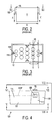
- FIGS. 1-3 illustrate a
typical battery pack 10, which includes abottom housing 11, a plurality ofcells 12 disposed within the housing, acell 13 disposed on the plurality ofcells 12, and aterminal block 14 disposed oncell 13. Persons skilled in the art will recognize that theterminal block 14 andcells art terminal block 14. - A
pack cover 15 carrying atower 16 is disposed onhousing 11 so as to containcells aperture 17 exposingterminal block 14 for electrical connection to the power tool (not shown). Thepack cover 15 may be held in place viascrews 19, or other means, so as adhesives, molten plastic, etc. - Typical battery packs include at least one
latch mechanism 18 for latching thebattery pack 10 to the power tool, or cordless device.Latch mechanism 18 typically includes abutton 18B disposed onhousing 11, alatch hook 18L movably connected tobutton 18B and movable between a latching position and an unlatched position, and aspring 18S for biasinglatch hook 18L towards the latching position. Accordingly, in order to unlatch a battery pack from the power tool, the user needs to press button(s) 18B with one hand, movinglatch hook 18L towards the unlatched position, and pull out thebattery pack 10, while holding the power tool with the other hand. - Typically
battery packs 10 have twobuttons 18B on opposing walls ofhousing 11. Accordingly, the operator needs to bridge the composite distance of A, B and C, i.e., the lengths along thehousing 11, in order to press bothbuttons 18B andunlatch battery pack 10. However, as the number ofcells 12 is increased to obtain higher voltages, the composite distance (A+B+C) is also increased, until the operator cannot easily reach bothbuttons 18B. - In accordance with the present invention, an improved battery pack is employed. The battery pack includes a housing with opposing walls, a plurality of cells disposed within the housing, at least two terminals electrically connected to the cells, a latching mechanism disposed on each opposing wall for latching the battery pack to a cordless device, each latching mechanism including a latch and a button disposed on the wall for moving the latch between unlatching and latching positions, the latching buttons being disposed along a first plane, the first plane being substantially vertical, wherein the number of cells disposed along the first plane is smaller than the number of cells disposed along a second plane substantially parallel to the first plane. The battery pack may also include a stacked cell disposed on the plurality of cells. The stacked cell may be disposed along the first plane. However, the stacked cell is not included in the number of cells disposed along the first plane.
- Additional features and benefits of the present invention are described, and will be apparent from, the accompanying drawings and the detailed description below.
- The accompanying drawings illustrate preferred embodiments of the invention according to the practical application of the principles thereof, and in which:
- FIG. 1 is an exploded perspective view of a prior art battery pack;
- FIG. 2 is a rear view of the lower portion of the battery pack of FIG. 1;
- FIG. 3 is a top plan view of the lower portion of FIG. 2 along line III-III;
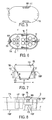
- FIG. 4 is a side view of a lower portion of the improved battery pack according to a first embodiment of the present invention;
- FIG. 5 is a bottom plan view of the lower portion of FIG. 4 along line V-V;
- FIG. 6 is a top plan view of the lower portion of FIG. 4 along line VI-VI;
- FIG. 7 is a rear elevational view of the lower portion of FIG. 4 along line VII-VII; and
- FIG. 8 is a side view of a lower portion of the improved battery pack according to a second embodiment of the present invention.
-
- The invention is now described with reference to the accompanying figures, wherein like numerals designate like parts. Referring to FIGS. 4-7, the
battery pack 100 has ahousing 11A,latch mechanisms 18 thereon, andcells 12 withinhousing 11A.Battery pack 100 may also have apack cover 15,tower 16,terminal block 14 and/orcell 13 as taught in the prior art. - Preferably each of two opposing walls of
housing 11A has afront portion 11F, arear portion 11R and achannel portion 11C disposed between front andrear portions channel portion 11C is depressed relative to front andrear portions rear portions channel portion 11C is not. -
Channel portion 11C may include a surface 11S. Preferably the distance between surface 11S and center plane Z is smaller than the distance between center plane Z and front and/orrear portions rear portions - Persons skilled in the art will recognize that
button 18B may be disposed on surface 11S or withinchannel portion 11C. However, persons skilled in the art should recognize thatbuttons 18B may be disposed outside ofchannel portion 11C. - By providing
such channel portions 11C, the effective distance betweenlatch buttons 18B, i.e, the composite distance, is about D+E+F, and thus is smaller than composite distance A+B+C, thus providing a more ergonomic access to thelatching buttons 18B. Preferable, distance D+E+F is about or less than 4 inches, whereas the distance A+B+C is about 4.5 inches. - In order to obtain such arrangement, it is preferable to arrange
cells 12 so that the number ofcells 12 disposed between thelatching buttons 18, or along plane X, is smaller than the number ofcells 12 disposed elsewhere in housing Y, e.g., along plane Y. Such cell arrangement permits the surface 11S to be closer to the center plane Z. - A second embodiment is shown in FIG. 8, where like numerals refer to like parts. The teachings of the first embodiment are incorporated herein.
Housing 11B, as before, may carrylatching buttons 18B, and may have front andrear portions Housing 11B may also have a bottom surface 11BP, which is substantially planar along plane H.A channel portion 11D is preferably disposed between front andrear portions latching buttons 18B. Preferably,channel portion 11D has a surface 11DP which is disposed betweenbuttons 18B and plane H. In other words, the distance between surface 11DP andbuttons 18B is smaller than the distance betweenbuttons 18B and plane H. Similarly, the distance between surface 11DP and top housing plane G is smaller than the distance between planes G and H, i.e., the height ofhousing 11. - In order to obtain such arrangement, it is preferable to arrange at least one of the cells 12 (
cell 12H) so that it lays horizontally, as opposed to theother cells 12 which stand vertically, inhousing 11. Such cell arrangement permits the surface 11DP to be closer to thebuttons 18B, etc. -
Housing 11 may also havevent holes 11 H disposed thereon. In addition,housing 11 may haveribs 11R to help locate thecells 12 withinhousing 11. Preferablyholes 11H are disposed betweenribs 11R and/or the walls ofhousing 11. - Persons skilled in the art may recognize other alternatives to the means disclosed herein. However, all these additions and/or alterations are considered to be equivalents of the present invention.
Claims (38)
- A battery pack (100) comprising:a housing (11A) comprising opposing walls;a plurality of cells (12) disposed within the housing (11A);at least two terminals (14) electrically connected to the cells (12);a latching mechanism (18) disposed on each opposing wall for latching the battery pack (100) to a cordless device, each latching mechanism (18) comprising a latch (18L) and a button (18B) disposed on the wall for moving the latch (18L) between unlatching and latching positions, the latching buttons (18B) being disposed along a first plane (X), the first plane (X) being substantially vertical;wherein number of cells (12) disposed along the first plane (X) is smaller than number of cells (12) disposed along a second plane (Y) substantially parallel to the first plane (X).
- A battery pack (100) as claimed in claim 1, wherein at least one wall has first (11F or 11R) and second (11C) portions.
- A battery pack (100) as claimed in claim 2, wherein at least one of the buttons (18B) is disposed on the second portion (11C) of the at least one of the walls.
- A battery pack (100) as claimed in either one of claims 2 or 3, wherein the first (11F or 11R) and second (11C) portions comprise substantially non-coplanar surfaces.
- A battery pack (100) as claimed in claim 4, wherein distance between the second portion surface (11C) and a center plane (Z) dissecting the housing (11A) is smaller than distance between the first portion surface (11F or 11R) and the center plane (Z).
- A battery pack (100) as claimed in any one of the preceding claims, wherein at least one of the cells (12), and preferably each of the cells (12), is vertical.
- A battery pack (100) as claimed in any one of the preceding claims, wherein the housing (11A) comprises a floor which is preferably substantially horizontal.
- A battery pack (100) as claimed in claim 7, wherein the latching buttons (18B) are disposed along a first line located at a first distance from the floor.
- A battery pack (100) as claimed in claim 8, wherein distance between the latching buttons (18B) along periphery of the housing (11A) is smaller than distance between two points along periphery of the housing (11A), the two points being contained within a second line parallel to the first line and located at the first distance from the floor.
- A battery pack (100) comprising:a housing (11A) comprising opposing walls, at least one of the walls having first (11F or 11R) and second (11C) portions, the first (11F or 11R) and second (11C) portions comprising substantially non-coplanar surfaces, the housing (11A) being dissected by a center plane (Z);a plurality of cells (12) disposed within the housing (11A);at least two terminals (14) electrically connected to the cells (12);a latching mechanism (18) disposed on the housing (11A) for latching the battery pack (100) to a cordless device, the latching mechanism (18) comprising a latch (18L) and a button (18B) disposed on the second portion (11C) for moving the latch (18L) between unlatching and latching positions;wherein distance between the second portion surface (11C) and the center plane (Z) is smaller than distance between the first portion surface (11F or 11R) and the center plane (Z).
- A battery pack (100) as claimed in claims 10, wherein at least one of the cells (12), and preferably each of the cells (12), is vertical.
- A battery pack (100) as claimed in either one of claims 10 or 11, wherein the housing (11A) comprises a floor which is preferably substantially horizontal.
- A battery pack (100) as claimed in any one of claims 10 to 12, further comprising a latching button (18B) on the other wall.
- A battery pack (100) as claimed in claim 13, wherein the latching buttons (18B) are disposed along a first line located at a first distance from the floor.
- A battery pack (100) as claimed in claim 14, wherein distance between the latching buttons (18B) along periphery of the housing (11A) is smaller than distance between two points along periphery of the housing (11A), the two points being contained within a second line parallel to the first line and located at the first distance from the floor.
- A battery pack (100) as claimed in any one of claims 13 to 15, wherein number of cells (12) disposed along a first plane (X) between the latching buttons (18B) is smaller than number of cells (12) disposed along a second plane (Y) substantially parallel to the first plane (X).
- A battery pack (100) comprising:a housing (11A) comprising a floor and opposing walls connected to the floor, at least one wall having first (11F or 11R) and second (11C) portions;a plurality of cells (12) disposed within the housing (11A);at least two terminals (14) electrically connected to the cells (12);a latching mechanism (18) disposed on each opposing wall for latching the battery pack (100) to a cordless device, each latching mechanism (18) comprising a latch (18L) and a button (18B) disposed on each wall for moving the latch (18L) between unlatching and latching positions, the latching buttons (18B) being disposed along a first line located at a first distance from the floor;wherein distance between the latching buttons (18B) along periphery of the housing (11A) is smaller than distance between two points along periphery of the housing (11A), the two points being contained within a second line parallel to the first line and located at the first distance from the floor and in the first portion (11F or 11R).
- A battery pack (100) as claimed in claim 17, wherein the first (11F or 11R) and second (11C) portions comprise substantially non-coplanar surfaces.
- A battery pack (100) as claimed in claim 18, wherein distance between the second portion surface (11C) and a center plane (Z) dissecting the housing (11A) is smaller than distance between the first portion surface (11F or 11R) and the center plane (Z).
- A battery pack (100) as claimed in any one of claims 17 to 19, wherein at least one of the cells (12), and preferably each of the cells (12), is vertical.
- A battery pack (100) as claimed in any one of claims 17 to 20, wherein number of cells (12) disposed along a first plane (X) between the latching buttons (18B) is smaller than number of cells (12) disposed along a second plane (Y) substantially parallel to the first plane (X).
- A battery pack (100) comprising:a housing (11B) comprising a first portion (11F or 11R) having a first floor (11BP) and first and second walls connected to the first floor (11BP), and a second portion (11D) having a second floor (11DP) and third and fourth walls connected to the second floor (11DP), where the first and second floors are non-coplanar; a plurality of cells (12) disposed within the housing (11B); andat least two terminals (14) electrically connected to the cells (12).
- A battery pack (100) as claimed in claim 22, further comprising first and second latching mechanisms (18) disposed on the housing (11B) for latching the battery pack (100) to a cordless device.
- A battery pack (100) as claimed in claim 23, wherein each latching mechanism (18) comprises a latch (18L) and a button (18B) connected to the latch (18L) for moving the latch (18L) between unlatching and latching positions.
- A battery pack (100) as claimed in claim 24, wherein at least one button (18B) is disposed on the second portion (11D).
- A battery pack (100) as claimed in either one of claims 24 or 25, wherein the latching buttons (18B) are disposed along a first line (18BP) located at a first distance from first floor plane (H).
- A battery pack (100) as claimed in claim 26, wherein distance between the latching buttons (18B) along periphery of the housing (11B) is smaller than distance between two points along periphery of the housing (11B), the two points being contained within a second line parallel to the first line and located at the first distance from the first floor plane (H).
- A battery pack (100) as claimed in any one of claims 24 to 27, wherein number of cells (12) disposed along a first plane (X) between the latching buttons (18B) is smaller than number of cells (12) disposed along a second plane (Y) substantially parallel to the first plane (X).
- A battery pack (100) as claimed in any one of claims 22 to 28, wherein the first (11F or 11R) and second (11D) portions comprise substantially non-coplanar surfaces.
- A battery pack (100) as claimed in claim 29, wherein distance between the second portion surface (11D) and a center plane (Z) dissecting the housing (11B) is smaller than distance between the first portion surface (11F or 11R) and the center plane (Z).
- A battery pack (100) as claimed in any one of claims 22 to 30, wherein at least one of the cells (12) is horizontal.
- A battery pack (100) as claimed in any one of claims 22 to 30, wherein at least one of the cells (12) is vertical.
- A battery pack (100) as claimed in any one of the preceding claims, further comprising a stacked cell (13) disposed on the plurality of cells (12).
- A battery pack (100) as claimed in claim 33, wherein the stacked cell (13) is disposed along the first plane (X).
- A battery pack (100) as claimed in claim 34, wherein the stacked cell (13) is not included in the number of cells (12) disposed along the first plane (X).
- A battery pack (100) as claimed in any one of claims 2, or 10 to 35, wherein the first portion surface (11F or 11R) and / or second portion surface (11C or 11D) is substantially vertical.
- A battery pack (100) as claimed in any one of claims 2, or 10 to 35, wherein the second portion surface (11C or 11D) is inclined.
- A battery pack (100) as claimed in any one of claims 2, or 10 to 37, wherein at least one of the buttons (18B) is disposed on the second portion surface (11C or 11D) of the at least one of the walls.
Priority Applications (1)
| Application Number | Priority Date | Filing Date | Title |
|---|---|---|---|
| EP05008354A EP1555703B1 (en) | 1999-07-15 | 2000-07-14 | Battery pack |
Applications Claiming Priority (2)
| Application Number | Priority Date | Filing Date | Title |
|---|---|---|---|
| US354405 | 1982-03-03 | ||
| US09/354,405 US6326101B1 (en) | 1999-07-15 | 1999-07-15 | Battery pack |
Related Child Applications (2)
| Application Number | Title | Priority Date | Filing Date |
|---|---|---|---|
| EP05008354A Division EP1555703B1 (en) | 1999-07-15 | 2000-07-14 | Battery pack |
| EP05008354.2 Division-Into | 2005-04-18 |
Publications (2)
| Publication Number | Publication Date |
|---|---|
| EP1069630A1 true EP1069630A1 (en) | 2001-01-17 |
| EP1069630B1 EP1069630B1 (en) | 2005-09-21 |
Family
ID=23393202
Family Applications (2)
| Application Number | Title | Priority Date | Filing Date |
|---|---|---|---|
| EP00306009A Expired - Lifetime EP1069630B1 (en) | 1999-07-15 | 2000-07-14 | Battery pack |
| EP05008354A Expired - Lifetime EP1555703B1 (en) | 1999-07-15 | 2000-07-14 | Battery pack |
Family Applications After (1)
| Application Number | Title | Priority Date | Filing Date |
|---|---|---|---|
| EP05008354A Expired - Lifetime EP1555703B1 (en) | 1999-07-15 | 2000-07-14 | Battery pack |
Country Status (10)
| Country | Link |
|---|---|
| US (5) | US6326101B1 (en) |
| EP (2) | EP1069630B1 (en) |
| JP (1) | JP2001043838A (en) |
| CN (1) | CN1178308C (en) |
| AT (2) | ATE305174T1 (en) |
| CA (2) | CA2597790C (en) |
| DE (2) | DE60022708T2 (en) |
| DK (1) | DK1069630T3 (en) |
| ES (1) | ES2244392T3 (en) |
| TW (1) | TW434925B (en) |
Cited By (1)
| Publication number | Priority date | Publication date | Assignee | Title |
|---|---|---|---|---|
| WO2002064322A1 (en) * | 2001-02-15 | 2002-08-22 | Atlas Copco Electric Tools Gmbh | Battery pack for an electric tool |
Families Citing this family (45)
| Publication number | Priority date | Publication date | Assignee | Title |
|---|---|---|---|---|
| US6326101B1 (en) * | 1999-07-15 | 2001-12-04 | Black & Decker Inc. | Battery pack |
| US7443137B2 (en) | 2000-08-11 | 2008-10-28 | Milwaukee Electric Tool Corporation | Adapter for a power tool battery |
| US7183745B2 (en) | 2000-08-11 | 2007-02-27 | Milwaukee Electric Tool Corporation | Adapter for a power tool battery |
| US6525511B2 (en) | 2000-08-11 | 2003-02-25 | Milwaukee Electric Tool Corporation | Adapter for a power tool battery |
| US8319357B2 (en) | 2002-06-06 | 2012-11-27 | Black & Decker Inc. | Starter system for portable internal combustion engine electric generators using a portable universal battery pack |
| US7687926B2 (en) * | 2002-06-06 | 2010-03-30 | Black & Decker Inc. | Starter system for portable internal combustion engine electric generators using a portable universal battery pack |
| US7989969B2 (en) | 2002-06-06 | 2011-08-02 | Black & Decker Inc. | Universal power tool battery pack coupled to a portable internal combustion engine |
| US7052799B2 (en) | 2002-06-27 | 2006-05-30 | Vocollect, Inc. | Wearable terminal with a battery latch mechanism |
| US6910911B2 (en) | 2002-06-27 | 2005-06-28 | Vocollect, Inc. | Break-away electrical connector |
| DE10229980A1 (en) * | 2002-07-03 | 2004-01-15 | Hilti Ag | battery pack |
| DE10313187A1 (en) * | 2003-03-25 | 2004-10-07 | Hilti Ag | Locking an accumulator module |
| TWI229490B (en) * | 2003-06-20 | 2005-03-11 | Ren-Tang Jang | Structure of power supply for external tool |
| US20050058890A1 (en) * | 2003-09-15 | 2005-03-17 | Kenneth Brazell | Removable battery pack for a portable electric power tool |
| US7273159B2 (en) * | 2004-11-08 | 2007-09-25 | Black & Decker Inc. | Cordless power tool system with improved power output |
| CN101395781B (en) | 2005-03-16 | 2011-09-14 | 福特全球技术公司 | Power supply temperature sensor and system |
| MX2007011126A (en) * | 2005-03-16 | 2007-11-13 | Ford Global Tech Llc | Power supply system. |
| US7604896B2 (en) * | 2005-03-16 | 2009-10-20 | Ford Global Technologies, Llc | High voltage battery assembly for a motor vehicle |
| US7586736B2 (en) * | 2005-07-11 | 2009-09-08 | Micro Power Electronics Inc. | Electrical insulation system and method for electrical power storage component separation |
| US20070240892A1 (en) * | 2005-11-04 | 2007-10-18 | Black & Decker Inc. | Cordless outdoor power tool system |
| US7497275B2 (en) * | 2005-11-04 | 2009-03-03 | Black & Decker Inc. | Cordless power tool system with improved power output |
| US8417185B2 (en) | 2005-12-16 | 2013-04-09 | Vocollect, Inc. | Wireless headset and method for robust voice data communication |
| US7773767B2 (en) | 2006-02-06 | 2010-08-10 | Vocollect, Inc. | Headset terminal with rear stability strap |
| US7885419B2 (en) | 2006-02-06 | 2011-02-08 | Vocollect, Inc. | Headset terminal with speech functionality |
| JP5187543B2 (en) * | 2006-05-11 | 2013-04-24 | 日立工機株式会社 | Battery pack for electric tools |
| US20070277987A1 (en) * | 2006-05-26 | 2007-12-06 | Meyer Gary D | Power tool, battery pack, and method of operating the same |
| JP4241810B2 (en) * | 2006-11-27 | 2009-03-18 | パナソニック電工株式会社 | Electric tool |
| TW200830603A (en) * | 2007-01-11 | 2008-07-16 | Mobiletron Electronics Co Ltd | Battery of power tool |
| US20090047572A1 (en) * | 2007-08-16 | 2009-02-19 | Micropower Electronics, Inc. | Controlled pressure release for packaged batteries and associated systems and methods |
| US8252441B2 (en) * | 2007-08-31 | 2012-08-28 | Micro Power Electronics, Inc. | Spacers for fixing battery cells within a battery package casing and associated systems and methods |
| US8679665B2 (en) * | 2007-12-10 | 2014-03-25 | Illinois Tool Works Inc. | Battery for a power tool |
| USD626949S1 (en) | 2008-02-20 | 2010-11-09 | Vocollect Healthcare Systems, Inc. | Body-worn mobile device |
| USD605629S1 (en) | 2008-09-29 | 2009-12-08 | Vocollect, Inc. | Headset |
| US8386261B2 (en) | 2008-11-14 | 2013-02-26 | Vocollect Healthcare Systems, Inc. | Training/coaching system for a voice-enabled work environment |
| DE102009012180A1 (en) * | 2009-02-27 | 2010-09-02 | Andreas Stihl Ag & Co. Kg | Battery pack for a power tool |
| US8160287B2 (en) | 2009-05-22 | 2012-04-17 | Vocollect, Inc. | Headset with adjustable headband |
| US8438659B2 (en) | 2009-11-05 | 2013-05-07 | Vocollect, Inc. | Portable computing device and headset interface |
| US8659397B2 (en) | 2010-07-22 | 2014-02-25 | Vocollect, Inc. | Method and system for correctly identifying specific RFID tags |
| USD643400S1 (en) | 2010-08-19 | 2011-08-16 | Vocollect Healthcare Systems, Inc. | Body-worn mobile device |
| USD643013S1 (en) | 2010-08-20 | 2011-08-09 | Vocollect Healthcare Systems, Inc. | Body-worn mobile device |
| KR101254881B1 (en) * | 2011-04-07 | 2013-04-15 | 로베르트 보쉬 게엠베하 | Battery pack having energy generating part |
| EP2739440B1 (en) | 2011-08-01 | 2016-10-05 | Ingersoll-Rand Company | Electric device with non-binding linear rails |
| US9660229B2 (en) * | 2011-08-01 | 2017-05-23 | Ingersoll-Rand Company | Battery pack release with tactile feedback for cordless power tools |
| US10573860B2 (en) * | 2013-11-19 | 2020-02-25 | Ingersoll-Rand Company | Cordless power tool batteries |
| USD772806S1 (en) | 2014-11-26 | 2016-11-29 | Techtronic Industries Co. Ltd. | Battery |
| US10158105B2 (en) | 2016-03-16 | 2018-12-18 | Tti (Macao Commercial Offshore) Limited | Battery pack latch mechanism |
Citations (3)
| Publication number | Priority date | Publication date | Assignee | Title |
|---|---|---|---|---|
| US5144217A (en) * | 1989-03-03 | 1992-09-01 | Black & Decker Inc. | Cordless tool battery housing and charging system |
| US5213913A (en) * | 1992-02-21 | 1993-05-25 | Snap-On Tools Corporation | Latching arrangement for battery pack |
| JPH0973890A (en) * | 1995-09-01 | 1997-03-18 | Makita Corp | Battery case |
Family Cites Families (8)
| Publication number | Priority date | Publication date | Assignee | Title |
|---|---|---|---|---|
| US3844000A (en) * | 1963-09-27 | 1974-10-29 | Siemon Co | Clasp |
| US4599283A (en) * | 1983-08-12 | 1986-07-08 | Enertronics, Inc. | Power cell assembly |
| US4616169A (en) * | 1985-04-08 | 1986-10-07 | Scovill Inc. | Battery-powered appliance |
| US4959280A (en) * | 1989-11-13 | 1990-09-25 | Eveready Battery Company, Inc. | Battery assembly |
| US5212021A (en) * | 1992-02-21 | 1993-05-18 | Duracell Inc. | Energy pack and individual battery cell cartridge |
| US6007939A (en) * | 1997-07-01 | 1999-12-28 | Porter-Cable Corporation | Battery pack for cordless tools |
| US5977746A (en) * | 1998-07-21 | 1999-11-02 | Stryker Corporation | Rechargeable battery pack and method for manufacturing same |
| US6326101B1 (en) * | 1999-07-15 | 2001-12-04 | Black & Decker Inc. | Battery pack |
-
1999
- 1999-07-15 US US09/354,405 patent/US6326101B1/en not_active Expired - Lifetime
- 1999-11-01 CA CA2597790A patent/CA2597790C/en not_active Expired - Fee Related
- 1999-11-01 CA CA002287859A patent/CA2287859C/en not_active Expired - Fee Related
- 1999-11-02 TW TW088119043A patent/TW434925B/en not_active IP Right Cessation
- 1999-11-19 CN CNB991248546A patent/CN1178308C/en not_active Expired - Fee Related
- 1999-11-24 JP JP11332679A patent/JP2001043838A/en not_active Withdrawn
-
2000
- 2000-07-14 EP EP00306009A patent/EP1069630B1/en not_active Expired - Lifetime
- 2000-07-14 ES ES00306009T patent/ES2244392T3/en not_active Expired - Lifetime
- 2000-07-14 AT AT00306009T patent/ATE305174T1/en not_active IP Right Cessation
- 2000-07-14 DE DE60022708T patent/DE60022708T2/en not_active Expired - Lifetime
- 2000-07-14 AT AT05008354T patent/ATE481747T1/en not_active IP Right Cessation
- 2000-07-14 DE DE60044980T patent/DE60044980D1/en not_active Expired - Lifetime
- 2000-07-14 DK DK00306009T patent/DK1069630T3/en active
- 2000-07-14 EP EP05008354A patent/EP1555703B1/en not_active Expired - Lifetime
-
2001
- 2001-09-21 US US09/960,551 patent/US6500581B2/en not_active Expired - Fee Related
-
2002
- 2002-11-05 US US10/288,633 patent/US6641950B2/en not_active Expired - Fee Related
-
2003
- 2003-08-18 US US10/642,860 patent/US7160644B2/en not_active Expired - Fee Related
-
2006
- 2006-12-07 US US11/635,212 patent/US7655350B2/en not_active Expired - Fee Related
Patent Citations (3)
| Publication number | Priority date | Publication date | Assignee | Title |
|---|---|---|---|---|
| US5144217A (en) * | 1989-03-03 | 1992-09-01 | Black & Decker Inc. | Cordless tool battery housing and charging system |
| US5213913A (en) * | 1992-02-21 | 1993-05-25 | Snap-On Tools Corporation | Latching arrangement for battery pack |
| JPH0973890A (en) * | 1995-09-01 | 1997-03-18 | Makita Corp | Battery case |
Non-Patent Citations (1)
| Title |
|---|
| PATENT ABSTRACTS OF JAPAN vol. 1997, no. 07 31 July 1997 (1997-07-31) * |
Cited By (1)
| Publication number | Priority date | Publication date | Assignee | Title |
|---|---|---|---|---|
| WO2002064322A1 (en) * | 2001-02-15 | 2002-08-22 | Atlas Copco Electric Tools Gmbh | Battery pack for an electric tool |
Also Published As
| Publication number | Publication date |
|---|---|
| CN1281267A (en) | 2001-01-24 |
| US20040051502A1 (en) | 2004-03-18 |
| US20020012832A1 (en) | 2002-01-31 |
| DK1069630T3 (en) | 2005-11-21 |
| ATE305174T1 (en) | 2005-10-15 |
| TW434925B (en) | 2001-05-16 |
| US7160644B2 (en) | 2007-01-09 |
| EP1069630B1 (en) | 2005-09-21 |
| ES2244392T3 (en) | 2005-12-16 |
| CA2287859C (en) | 2008-05-27 |
| US20030059672A1 (en) | 2003-03-27 |
| CA2597790A1 (en) | 2001-01-15 |
| US6326101B1 (en) | 2001-12-04 |
| EP1555703A3 (en) | 2007-04-25 |
| US6641950B2 (en) | 2003-11-04 |
| ATE481747T1 (en) | 2010-10-15 |
| DE60044980D1 (en) | 2010-10-28 |
| DE60022708T2 (en) | 2006-06-29 |
| JP2001043838A (en) | 2001-02-16 |
| EP1555703A2 (en) | 2005-07-20 |
| CA2287859A1 (en) | 2001-01-15 |
| CN1178308C (en) | 2004-12-01 |
| US7655350B2 (en) | 2010-02-02 |
| CA2597790C (en) | 2010-05-11 |
| DE60022708D1 (en) | 2006-02-02 |
| US6500581B2 (en) | 2002-12-31 |
| EP1555703B1 (en) | 2010-09-15 |
| US20070077486A1 (en) | 2007-04-05 |
Similar Documents
| Publication | Publication Date | Title |
|---|---|---|
| EP1555703B1 (en) | Battery pack | |
| EP0572189B1 (en) | Battery charging equipment for a cordless telephone | |
| US7618741B2 (en) | Battery pack, charger and terminal block arrangements for cordless power tool system | |
| US5633096A (en) | Battery holder for power driven-tools | |
| RU2419922C1 (en) | Storage battery and manual battery-driven machine using it | |
| US5229701A (en) | Battery charger for battery-operated equipment | |
| EP2787557B1 (en) | Battery packs for electric tools | |
| US6265845B1 (en) | Portable battery charger having a separate battery pack | |
| EP1780818A2 (en) | Battery pack charger and terminal block arrangements for cordless power tool system | |
| US6743545B2 (en) | Closed type battery case | |
| WO2013027772A1 (en) | Power source device | |
| JP5784413B2 (en) | Power supply | |
| US20220190610A1 (en) | Charger and Charger Housing With Water Discharge Structure | |
| JP5158564B2 (en) | battery pack | |
| JP7404100B2 (en) | electrical equipment | |
| JP6661701B2 (en) | Power supply | |
| JP2022090508A (en) | Electrical apparatus system and battery pack type apparatus | |
| EP0779693A1 (en) | A charging battery structure for hand phone | |
| JP2022125533A (en) | battery pack | |
| JP2024044441A (en) | containment box | |
| WO1999014864A1 (en) | Mobile telephone battery |
Legal Events
| Date | Code | Title | Description |
|---|---|---|---|
| PUAI | Public reference made under article 153(3) epc to a published international application that has entered the european phase |
Free format text: ORIGINAL CODE: 0009012 |
|
| AK | Designated contracting states |
Kind code of ref document: A1 Designated state(s): AT BE CH CY DE DK ES FI FR GB GR IE IT LI LU MC NL PT SE |
|
| AX | Request for extension of the european patent |
Free format text: AL;LT;LV;MK;RO;SI |
|
| 17P | Request for examination filed |
Effective date: 20010615 |
|
| AKX | Designation fees paid |
Free format text: AT BE CH CY DE DK ES FI FR GB GR IE IT LI LU MC NL PT SE |
|
| 17Q | First examination report despatched |
Effective date: 20040726 |
|
| GRAP | Despatch of communication of intention to grant a patent |
Free format text: ORIGINAL CODE: EPIDOSNIGR1 |
|
| GRAS | Grant fee paid |
Free format text: ORIGINAL CODE: EPIDOSNIGR3 |
|
| GRAA | (expected) grant |
Free format text: ORIGINAL CODE: 0009210 |
|
| AK | Designated contracting states |
Kind code of ref document: B1 Designated state(s): AT BE CH CY DE DK ES FI FR GB GR IE IT LI LU MC NL PT SE |
|
| PG25 | Lapsed in a contracting state [announced via postgrant information from national office to epo] |
Ref country code: CH Free format text: LAPSE BECAUSE OF FAILURE TO SUBMIT A TRANSLATION OF THE DESCRIPTION OR TO PAY THE FEE WITHIN THE PRESCRIBED TIME-LIMIT Effective date: 20050921 Ref country code: LI Free format text: LAPSE BECAUSE OF FAILURE TO SUBMIT A TRANSLATION OF THE DESCRIPTION OR TO PAY THE FEE WITHIN THE PRESCRIBED TIME-LIMIT Effective date: 20050921 Ref country code: BE Free format text: LAPSE BECAUSE OF FAILURE TO SUBMIT A TRANSLATION OF THE DESCRIPTION OR TO PAY THE FEE WITHIN THE PRESCRIBED TIME-LIMIT Effective date: 20050921 Ref country code: FI Free format text: LAPSE BECAUSE OF FAILURE TO SUBMIT A TRANSLATION OF THE DESCRIPTION OR TO PAY THE FEE WITHIN THE PRESCRIBED TIME-LIMIT Effective date: 20050921 Ref country code: AT Free format text: LAPSE BECAUSE OF FAILURE TO SUBMIT A TRANSLATION OF THE DESCRIPTION OR TO PAY THE FEE WITHIN THE PRESCRIBED TIME-LIMIT Effective date: 20050921 |
|
| REG | Reference to a national code |
Ref country code: GB Ref legal event code: FG4D |
|
| REG | Reference to a national code |
Ref country code: CH Ref legal event code: EP |
|
| REG | Reference to a national code |
Ref country code: IE Ref legal event code: FG4D |
|
| REF | Corresponds to: |
Ref document number: 60022708 Country of ref document: DE Date of ref document: 20051027 Kind code of ref document: P |
|
| REG | Reference to a national code |
Ref country code: DK Ref legal event code: T3 |
|
| REG | Reference to a national code |
Ref country code: SE Ref legal event code: TRGR |
|
| REG | Reference to a national code |
Ref country code: ES Ref legal event code: FG2A Ref document number: 2244392 Country of ref document: ES Kind code of ref document: T3 |
|
| PG25 | Lapsed in a contracting state [announced via postgrant information from national office to epo] |
Ref country code: GR Free format text: LAPSE BECAUSE OF FAILURE TO SUBMIT A TRANSLATION OF THE DESCRIPTION OR TO PAY THE FEE WITHIN THE PRESCRIBED TIME-LIMIT Effective date: 20051221 |
|
| REF | Corresponds to: |
Ref document number: 60022708 Country of ref document: DE Date of ref document: 20060202 Kind code of ref document: P |
|
| PG25 | Lapsed in a contracting state [announced via postgrant information from national office to epo] |
Ref country code: PT Free format text: LAPSE BECAUSE OF FAILURE TO SUBMIT A TRANSLATION OF THE DESCRIPTION OR TO PAY THE FEE WITHIN THE PRESCRIBED TIME-LIMIT Effective date: 20060221 |
|
| REG | Reference to a national code |
Ref country code: CH Ref legal event code: PL |
|
| ET | Fr: translation filed | ||
| PG25 | Lapsed in a contracting state [announced via postgrant information from national office to epo] |
Ref country code: IE Free format text: LAPSE BECAUSE OF NON-PAYMENT OF DUE FEES Effective date: 20060714 |
|
| PLBE | No opposition filed within time limit |
Free format text: ORIGINAL CODE: 0009261 |
|
| STAA | Information on the status of an ep patent application or granted ep patent |
Free format text: STATUS: NO OPPOSITION FILED WITHIN TIME LIMIT |
|
| PG25 | Lapsed in a contracting state [announced via postgrant information from national office to epo] |
Ref country code: MC Free format text: LAPSE BECAUSE OF NON-PAYMENT OF DUE FEES Effective date: 20060731 |
|
| 26N | No opposition filed |
Effective date: 20060622 |
|
| REG | Reference to a national code |
Ref country code: IE Ref legal event code: MM4A |
|
| PG25 | Lapsed in a contracting state [announced via postgrant information from national office to epo] |
Ref country code: LU Free format text: LAPSE BECAUSE OF NON-PAYMENT OF DUE FEES Effective date: 20060714 |
|
| PGFP | Annual fee paid to national office [announced via postgrant information from national office to epo] |
Ref country code: DK Payment date: 20080729 Year of fee payment: 9 Ref country code: ES Payment date: 20080728 Year of fee payment: 9 |
|
| PG25 | Lapsed in a contracting state [announced via postgrant information from national office to epo] |
Ref country code: CY Free format text: LAPSE BECAUSE OF FAILURE TO SUBMIT A TRANSLATION OF THE DESCRIPTION OR TO PAY THE FEE WITHIN THE PRESCRIBED TIME-LIMIT Effective date: 20050921 |
|
| PGFP | Annual fee paid to national office [announced via postgrant information from national office to epo] |
Ref country code: FR Payment date: 20080729 Year of fee payment: 9 Ref country code: IT Payment date: 20080724 Year of fee payment: 9 Ref country code: NL Payment date: 20080724 Year of fee payment: 9 |
|
| PGFP | Annual fee paid to national office [announced via postgrant information from national office to epo] |
Ref country code: SE Payment date: 20080729 Year of fee payment: 9 |
|
| REG | Reference to a national code |
Ref country code: DK Ref legal event code: EBP |
|
| EUG | Se: european patent has lapsed | ||
| NLV4 | Nl: lapsed or anulled due to non-payment of the annual fee |
Effective date: 20100201 |
|
| REG | Reference to a national code |
Ref country code: FR Ref legal event code: ST Effective date: 20100331 |
|
| PG25 | Lapsed in a contracting state [announced via postgrant information from national office to epo] |
Ref country code: FR Free format text: LAPSE BECAUSE OF NON-PAYMENT OF DUE FEES Effective date: 20090731 |
|
| PG25 | Lapsed in a contracting state [announced via postgrant information from national office to epo] |
Ref country code: DK Free format text: LAPSE BECAUSE OF NON-PAYMENT OF DUE FEES Effective date: 20090731 |
|
| REG | Reference to a national code |
Ref country code: ES Ref legal event code: FD2A Effective date: 20090715 |
|
| PG25 | Lapsed in a contracting state [announced via postgrant information from national office to epo] |
Ref country code: ES Free format text: LAPSE BECAUSE OF NON-PAYMENT OF DUE FEES Effective date: 20090715 |
|
| PG25 | Lapsed in a contracting state [announced via postgrant information from national office to epo] |
Ref country code: IT Free format text: LAPSE BECAUSE OF NON-PAYMENT OF DUE FEES Effective date: 20090714 |
|
| PG25 | Lapsed in a contracting state [announced via postgrant information from national office to epo] |
Ref country code: SE Free format text: LAPSE BECAUSE OF NON-PAYMENT OF DUE FEES Effective date: 20090715 |
|
| PG25 | Lapsed in a contracting state [announced via postgrant information from national office to epo] |
Ref country code: NL Free format text: LAPSE BECAUSE OF NON-PAYMENT OF DUE FEES Effective date: 20100201 |
|
| PGFP | Annual fee paid to national office [announced via postgrant information from national office to epo] |
Ref country code: DE Payment date: 20130729 Year of fee payment: 14 |
|
| PGFP | Annual fee paid to national office [announced via postgrant information from national office to epo] |
Ref country code: GB Payment date: 20130729 Year of fee payment: 14 |
|
| REG | Reference to a national code |
Ref country code: DE Ref legal event code: R119 Ref document number: 60022708 Country of ref document: DE |
|
| GBPC | Gb: european patent ceased through non-payment of renewal fee |
Effective date: 20140714 |
|
| PG25 | Lapsed in a contracting state [announced via postgrant information from national office to epo] |
Ref country code: DE Free format text: LAPSE BECAUSE OF NON-PAYMENT OF DUE FEES Effective date: 20150203 |
|
| REG | Reference to a national code |
Ref country code: DE Ref legal event code: R119 Ref document number: 60022708 Country of ref document: DE Effective date: 20150203 |
|
| PG25 | Lapsed in a contracting state [announced via postgrant information from national office to epo] |
Ref country code: GB Free format text: LAPSE BECAUSE OF NON-PAYMENT OF DUE FEES Effective date: 20140714 |