EP1069672A2 - Power supply with transformer choke - Google Patents
Power supply with transformer choke Download PDFInfo
- Publication number
- EP1069672A2 EP1069672A2 EP00113753A EP00113753A EP1069672A2 EP 1069672 A2 EP1069672 A2 EP 1069672A2 EP 00113753 A EP00113753 A EP 00113753A EP 00113753 A EP00113753 A EP 00113753A EP 1069672 A2 EP1069672 A2 EP 1069672A2
- Authority
- EP
- European Patent Office
- Prior art keywords
- output
- choke converter
- voltage
- choke
- comparator
- Prior art date
- Legal status (The legal status is an assumption and is not a legal conclusion. Google has not performed a legal analysis and makes no representation as to the accuracy of the status listed.)
- Withdrawn
Links
Images

Classifications
-
- H—ELECTRICITY
- H02—GENERATION; CONVERSION OR DISTRIBUTION OF ELECTRIC POWER
- H02M—APPARATUS FOR CONVERSION BETWEEN AC AND AC, BETWEEN AC AND DC, OR BETWEEN DC AND DC, AND FOR USE WITH MAINS OR SIMILAR POWER SUPPLY SYSTEMS; CONVERSION OF DC OR AC INPUT POWER INTO SURGE OUTPUT POWER; CONTROL OR REGULATION THEREOF
- H02M3/00—Conversion of dc power input into dc power output
- H02M3/02—Conversion of dc power input into dc power output without intermediate conversion into ac
- H02M3/04—Conversion of dc power input into dc power output without intermediate conversion into ac by static converters
- H02M3/10—Conversion of dc power input into dc power output without intermediate conversion into ac by static converters using discharge tubes with control electrode or semiconductor devices with control electrode
-
- H—ELECTRICITY
- H02—GENERATION; CONVERSION OR DISTRIBUTION OF ELECTRIC POWER
- H02M—APPARATUS FOR CONVERSION BETWEEN AC AND AC, BETWEEN AC AND DC, OR BETWEEN DC AND DC, AND FOR USE WITH MAINS OR SIMILAR POWER SUPPLY SYSTEMS; CONVERSION OF DC OR AC INPUT POWER INTO SURGE OUTPUT POWER; CONTROL OR REGULATION THEREOF
- H02M1/00—Details of apparatus for conversion
- H02M1/32—Means for protecting converters other than automatic disconnection
-
- H—ELECTRICITY
- H02—GENERATION; CONVERSION OR DISTRIBUTION OF ELECTRIC POWER
- H02J—CIRCUIT ARRANGEMENTS OR SYSTEMS FOR SUPPLYING OR DISTRIBUTING ELECTRIC POWER; SYSTEMS FOR STORING ELECTRIC ENERGY
- H02J7/00—Circuit arrangements for charging or depolarising batteries or for supplying loads from batteries
- H02J7/0029—Circuit arrangements for charging or depolarising batteries or for supplying loads from batteries with safety or protection devices or circuits
Definitions
- the invention relates to a direct current converter, namely a choke converter a controllable switch, with a device for controlling the controllable switch and with a device for detecting its output current.
- a DC voltage step-down converter is also known differs only from the choke converter known from the above-mentioned DE 196 12 365 differs in that it has no oscillator that has a switching frequency specifies, but is self-oscillating: the electronic switch is as long conductive until the current flowing through the choke exceeds a limit, and blocks until the output voltage has dropped below a certain value.
- WO 98/24170 a self-oscillating throttle converter is known, the Vibration behavior is determined only by its output voltage, and the additionally a device with a measuring resistor to limit the inductor current having.
- a choke converter for charging batteries is known from EP 0752748. He contains an electronic switch and a current measuring resistor, through which the current flowing through the choke is measured and provided the battery voltage is below a certain value, the electronic switch is switched on and off in this way will result in a charging current that is constant over time. Then the battery so far charged that their voltage is above the certain value, the electronic switches depending on the output voltage of the choke converter controlled in such a way that it remains constant.
- a self-oscillating throttle converter is known from WO 99/13559 Output current measured by a current measuring resistor and kept constant becomes. However, as the input voltage increases, the output current increases corresponding.
- a simply constructed choke converter to be specified, which is specially designed for charging a rechargeable battery, i.e. the independent from the current input voltage to the respective one State of charge of the battery and the prevailing environmental conditions (temperature) adjusted electricity supplies.
- the choke converter according to the invention has a device that the output current depending on the particular Controls output and input voltage. Since when using the invention Choke converter to charge an accumulator the output voltage of the choke converter is specified by the connected accumulator, and the respective In this way, the throttle converter always delivers the state of charge of the battery a current that is adapted to the respective state of charge of the battery.
- a choke converter according to the invention has a controllable switch, a device to control the controllable switch, a device for detecting the Output voltage of the choke converter and a device for detecting the output current of the throttle converter.
- the choke converter is via its input terminal connectable with a power supply, for example.
- the choke converter has the input voltage applied to its input terminal a lower output voltage.
- At its output terminal should preferably an accumulator can be connected. Since the Battery voltage changes very slowly, the operation of the invention Choke converter first described for the case of constant output voltage, which is determined by the battery voltage.
- the controllable switch preferably an electronic switch, in particular a Transistor
- the control device is controlled by the control device in a manner known per se, i.e. opened and closed again and again one after the other.
- a current flows from the input terminal over the Switch and the choke in the accumulator, making magnetic in the choke Energy is stored.
- the switch open i.e. in the blocking phase of the transistor, the magnetic energy is converted into electrical energy, so that a Current flows from the choke into the accumulator, the circuit in itself is known to be closed via a diode.
- the facility for recording the Output current of the choke converter according to the invention preferably a current measuring resistor, recorded both in the lead phase and the blocking phase of the electronic Switch the output current of the choke converter.
- the control device of the invention Choke converter closes the switch when the output current is up has decreased a certain first value and opens the switch when the Output current has risen to a certain second value. Since the invention Choke converter is thus controlled by its output current this is independent of the level of the input voltage.
- the choke converter according to the invention is designed so that with increasing output voltage of the Choke converter the first and second specific value change so that the switch remains open longer than before, so that the time-averaged output current of the Throttle converter decreases.
- the choke converter according to the invention is also so designed that the first even with a larger input voltage of the choke converter and change the second specific value so that the switch remains open longer than before.
- the so-called memory delay time of the electronic Switch compensates that, especially at large voltages to be switched delayed opening of the switch and thus a larger output current leads than would be the case with an ideal choke converter. Therefore, the invention Choke converter without problems with different input voltages operated without affecting the size of its output current.
- the choke converter according to the invention is preferably self-oscillating, i.e. contains no oscillator to control the opening and closing of the controllable switch.
- the choke converter according to the invention has a control input via which the Choke converter can be switched off. This can be done, for example, by a charge control device take place when a fully charged state is reached the throttle converter connected accumulator emits a corresponding signal.
- the control device has a first comparator Hysteresis and a first reference voltage source.
- the hysteresis of the first Comparator is generated in that the first reference voltage source two different Provides reference voltages depending on whether the output of the first comparator is "low” or "high".
- An advantageous choke converter also includes an arrangement for switching off the Choke converter at an input voltage that is necessary for the correct operation of the Throttle converter is too low, i.e. if the voltage at the input terminals below If a minimum input voltage drops, the choke converter switches off automatically.
- a throttle converter that is particularly advantageous for charging a rechargeable battery is according to the invention designed so that at low input voltage its output resistance is practically infinite. This can be done, for example, by opening at least a controllable switch through which the output terminals from the circuit of the choke converter, or a current flow between the output terminals is prevented. In this way, it is ensured that a Output terminals of the choke converter connected battery does not have the Choke converter can discharge if the input terminals of the choke converter (accidentally) are short-circuited or there is a voltage that is lower than that Battery voltage.
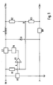
- the choke converter according to the invention shown in FIG. 1 contains a controllable one Switch LS and a choke L, which in a manner known per se between an input terminal Ue and a first output terminal Ua + are connected in series.
- the Connection point between the controllable switch LS and the choke L is with the Cathode of a freewheeling diode D connected.
- the anode of the freewheeling diode D is grounded and connected to one end of a current measuring resistor RM.
- the other end of the Current measuring resistor RM is connected to a second output terminal Ua.
- first resistor R1 is connected between the input terminal Ue and a point B, the via a second resistor R2 with the first output terminal Ua + and a third resistor R3 is connected to the second output terminal Ua.
- the Point B is also connected to the inverting input of a first comparator K1, its output via a driver TR with a control input of the controllable Switch LS is connected.
- the non-inverting input of the first comparator K1 is connected to a first reference voltage source U1, which is between the input terminal Ue and ground is switched.
- the first comparator K1 and the first reference voltage source U1 are connected together in such a way that that the reference voltage supplied by the first reference voltage source U1 Uref1 (point A) takes two different values, depending on whether the The output of the first comparator K1 is "low” or "high", i.e. the first comparator K1 exhibits hysteresis because its breakover voltage (point A) has a value other than its reverse tipping voltage (point A).
- point B there is a potential that is created by the Voltage drops across the resistors R1, R2, R3 and RM is determined and thus by the input voltage, the output voltage and the output current.
- the Input voltage is namely through the first, third and the current measuring resistor divided the output voltage by the second and third resistor.
- the first comparator K1 compares the voltage at point B with the voltage at point A. As long as the voltage at point B is less than the voltage at point A, the is Output of the first comparator K1 to "high” and vice versa: the output of the first Comparator K1 is "low” as long as the voltage at point B is greater than that Voltage at point A.
- FIG. 2 A preferred embodiment of the choke converter according to the invention is shown in FIG. 2 shown. This embodiment differs from the choke converter according to the invention 1 by an arrangement for switching off the choke converter low input voltage and an arrangement for preventing the discharge of a accumulator connected to the choke converter via the choke converter low input voltage.
- the arrangement for switching off the choke converter at low input voltage has a second reference voltage source U2, which is between the input terminal Ue and ground is connected, and a second comparator K2, the non-inverting Input with the output of the first comparator K1, its inverting Input with the second reference voltage source U2 and its output with the Driver TR is connected.
- the second comparator K2 compares the output voltage of the first comparator K1 with one of the second reference voltage source U2 supplied second reference voltage Uref2. At low input voltage, i.e. as long as the input voltage is below the second reference voltage Uref2, the output of the second comparator K2 remains at "low", so that the driver TR the controllable switch LS is kept open and the throttle converter does not oscillate can.
- the input voltage is above the second reference voltage URef2
- the output voltage of the second comparator K2 follows the output voltage of the first comparator K1, i.e. the controllable switch LS is from the first Comparator K1 controlled via the second comparator K2 and the driver TR.
- the arrangement for preventing the discharge of a connected to the choke converter Accumulator points over the choke converter at low input voltage a second controllable switch S between the second resistor R2 and the first output terminal Ua + is arranged, and its control input via a tenth resistor R10 is connected to the input terminal Ue.
- the second Controllable switch S preferably consists of an electronic switch, for example a transistor whose base is connected to the tenth resistor R10 is. When the input voltage is low, the second controllable switch S is open, so that the output resistance of the choke converter is practically infinite, and the Accumulator cannot discharge through the second and third resistor R2, R3.
- the first reference voltage source U1 consists of a fourth, fifth and sixth resistor R4, R5, R6 connected in series between the input terminal Ue and ground are connected, and a first Zener diode ZD1, the anode of which Ground and one end of the sixth resistor R6 is connected and the Cathode is connected to the fourth and fifth resistor R4, R5.
- the other The end of the sixth resistor R6 is connected to the non-inverting input of the first Comparator K1 (point A) and one end of an eighth resistor R8 connected.
- the other end of the eighth resistor R8 is through a seventh resistor R7 with the input terminal Ue and via a ninth resistor R9 with the output of the first comparator K1.
- the second reference voltage source U2 consists of a second Zener diode ZD2, its anode with ground and its cathode with the inverting input of the second comparator K2 and an eleventh Resistor R11 is connected to the input terminal Ue.
- the reference voltage Uref1 (point A) is the Zener voltage divided across the fifth and sixth resistors R5, R6, that from the input voltage through the fourth resistor R4 and the first Zener diode ZD1 is generated. As mentioned above, it has two different types Values depending on whether the output of the first comparator is "low” or “high”. Lies namely the output of the first comparator K1 to "high”, the voltage is on Point A (breakdown voltage) by the divided Zener voltage and the over sixth, seventh and eighth resistor R6, R7, R8 divided input voltage certainly. If, on the other hand, the output of the first comparator K1 is at "low”, So is the ninth resistor R9 of the series circuit from the sixth and eighth Resistor R6, R8 connected in parallel.
- the voltage at point A due to the divided Zener tension and the one above the sixth, seventh and eighth resistor R6, R7, R8 and on the other hand the seventh and ninth resistor R7, R9 divided input voltage determined.
- the difference the hysteresis voltage is between the breakover voltage and the breakdown voltage.
- the seventh R7 and ninth resistor R9 also serve as pull-up resistors for the output of the first comparator K1.
- the output of the first comparator K1 is "low", i.e. the output voltage of the first comparator K1 the reference voltage Uref2 of the second reference voltage source Does not exceed U2, the output of the second comparator K2 remains also on “low”.
- the driver TR is not activated and the controllable one Switch LS remains open.
- the output of the first comparator K1 is present "high”, i.e. the output voltage of the first comparator K1 is greater than that Reference voltage Uref2 of the second reference voltage source U2, is also the Output of the second comparator K2 to "high”. This controls the driver TR, if not the output of the second comparator K2 via the control input Stop a shutdown signal is supplied.
Abstract
Description
Die Erfindung betrifft einen Gleichstromwandler, nämlich einen Drosselwandler mit einem steuerbaren Schalter, mit einer Einrichtung zur Steuerung des steuerbaren Schalters und mit einer Einrichtung zur Erfassung seines Ausgangsstroms.The invention relates to a direct current converter, namely a choke converter a controllable switch, with a device for controlling the controllable switch and with a device for detecting its output current.
Aus der DE 196 12 365 ist ein Drosselwandler, nämlich ein Gleichspannungs-Abwärtswandler bekannt. Der Drosselwandler schwingt mit einer von einem Oszillator vorgegebenen Schaltfrequenz. Um die Ausgangsspannung des Wandlers weitgehend unabhängig von der Belastung einzuhalten, wird die Ausgangsspannung einer Steuervorrichtung zugeführt, die einen elektronischen Schalter mit einem entsprechend eingestellten Tastverhältnis ansteuert. Um zu verhindern, daß der durch die Drossel fließende Strom einen vorbestimmten Wert überschreitet, wird zusätzlich von der Steuervorrichtung auch der während der Leitphase des elektronischen Schalters durch die Drossel fließende Strom mittels eines Meßwiderstands erfaßt und durch den elektronischen Schalter erforderlichenfalls unterbrochen. Hierdurch wird auch verhindert, daß die Ausgangsspannung einen unerwünscht hohen Wert annimmt.From DE 196 12 365 there is a choke converter, namely a direct voltage step-down converter known. The throttle converter vibrates with a predetermined by an oscillator Switching frequency. To the output voltage of the converter largely Regardless of the load, the output voltage of a control device fed an electronic switch with an appropriately set Controlled duty cycle. To prevent the flow through the throttle Current exceeds a predetermined value, is additionally from the control device also during the control phase of the electronic switch through the choke flowing current detected by means of a measuring resistor and by the electronic Switch interrupted if necessary. This also prevents the Output voltage assumes an undesirably high value.
Aus der DE 33 10 678 ist ebenfalls ein Gleichspannungs-Abwärtswandler bekannt, der sich von dem aus der oben genannten DE 196 12 365 bekannten Drosselwandler nur dadurch unterscheidet, daß er keinen Oszillator aufweist, der eine Schaltfrequenz vorgibt, sondern selbstschwingend aufgebaut ist: der elektronische Schalter ist solange leitend bis der durch die Drossel fließende Strom einen Grenzwert überschreitet, und sperrt solange, bis die Ausgangsspannung unter einen bestimmten Wert abgefallen ist. Aus der WO 98/24170 ist ein selbstschwingender Drosselwandler bekannt, dessen Schwingungsverhalten nur durch seine Ausgangsspannung bestimmt ist, und der zusätzlich eine Einrichtung mit einem Meßwiderstand zur Begrenzung des Drosselstroms aufweist.From DE 33 10 678 a DC voltage step-down converter is also known differs only from the choke converter known from the above-mentioned DE 196 12 365 differs in that it has no oscillator that has a switching frequency specifies, but is self-oscillating: the electronic switch is as long conductive until the current flowing through the choke exceeds a limit, and blocks until the output voltage has dropped below a certain value. From WO 98/24170 a self-oscillating throttle converter is known, the Vibration behavior is determined only by its output voltage, and the additionally a device with a measuring resistor to limit the inductor current having.
Alle genannten Drosselwandler werden somit durch ihre Ausgangsspannung gesteuert. Der durch die Drossel fließende Strom ist nur dann erfaßbar, wenn der elektronische Schalter geschlossen ist, wobei die Erfassung nur zur Strombegrenzung dient.All of the choke converters mentioned are thus controlled by their output voltage. The current flowing through the choke can only be detected if the electronic Switch is closed, the detection only serves to limit the current.
Aus der DE 39 21 955 ist ein Schaltregler bekannt, dessen Ausgangsleistung regelbar ist. Dazu wird die Ausgangsspannung und der Ausgangsstrom erfaßt. Allerdings wird der Ausgangsstrom nur dann erfaßt, wenn der elektronische Schalter geöffnet ist.From DE 39 21 955 a switching regulator is known, the output power of which can be regulated is. For this purpose, the output voltage and the output current are recorded. However the output current is only detected when the electronic switch is open.
Aus der EP 0752748 ist ein Drosselwandler zur Aufladung von Batterien bekannt. Er enthält einen elektronischen Schalter und einen Strommeßwiderstand, durch den der durch die Drossel fließende Strom gemessen und, sofern die Batteriespannung unter einem bestimmten Wert liegt, der elektronische Schalter derart ein- und ausgeschaltet wird, daß sich ein im zeitlichen Mittel konstanter Ladestrom ergibt. Ist die Batterie dann so weit aufgeladen, daß ihre Spannung über dem bestimmten Wert liegt, wird der elektronische Schalter in Abhängigkeit von der Ausgangsspannung des Drosselwandlers derart angesteuert, daß diese konstant bleibt.A choke converter for charging batteries is known from EP 0752748. He contains an electronic switch and a current measuring resistor, through which the current flowing through the choke is measured and provided the battery voltage is below a certain value, the electronic switch is switched on and off in this way will result in a charging current that is constant over time. Then the battery so far charged that their voltage is above the certain value, the electronic switches depending on the output voltage of the choke converter controlled in such a way that it remains constant.
Aus der WO 99/13559 ist ein selbstschwingender Drosselwandler bekannt, dessen Ausgangsstrom durch einen Strommeßwiderstand gemessen und konstant gehalten wird. Bei zunehmender Eingangsspannung erhöht sich jedoch der Ausgangsstrom entsprechend.A self-oscillating throttle converter is known from WO 99/13559 Output current measured by a current measuring resistor and kept constant becomes. However, as the input voltage increases, the output current increases corresponding.
Es ist Aufgabe der vorliegenden Erfindung einen einfach aufgebauten Drosselwandler anzugeben, der speziell für das Laden eines Akkumulators ausgelegt ist, d.h. der unabhängig von der gerade herrschenden Eingangsspannung einen an den jeweiligen Ladezustand des Akkumulators und die herrschenden Umgebungsbedingungen (Temperatur) anpaßten Strom liefert. Ein nahezu voll aufgeladener Akkumulator kann nämlich nur noch einen kleinen Strom aufnehmen, wogegen ein fast leerer Akkumulator einen vergleichsweise großen Strom aufnehmen kann.It is an object of the present invention to have a simply constructed choke converter to be specified, which is specially designed for charging a rechargeable battery, i.e. the independent from the current input voltage to the respective one State of charge of the battery and the prevailing environmental conditions (temperature) adjusted electricity supplies. An almost fully charged battery can take up only a small current, whereas an almost empty accumulator one can draw a comparatively large current.
Die Lösung dieser Aufgabe erfolgt dadurch, daß der erfindungsgemäße Drosselwandler eine Einrichtung aufweist, die den Ausgangsstrom abhängig von der jeweiligen Ausgangs- und Eingangsspannung steuert. Da bei Verwendung des erfindungsgemäßen Drosselwandlers zur Aufladung eines Akkumulators die Ausgangsspannung des Drosselwandlers von dem angeschlossenen Akkumulator vorgegeben wird, und den jeweiligen Ladezustand des Akkus widerspiegelt, liefert auf diese Weise der Drosselwandler immer einen Strom, der an den jeweiligen Ladezustand des Akkumulators angepaßt ist.This object is achieved in that the choke converter according to the invention has a device that the output current depending on the particular Controls output and input voltage. Since when using the invention Choke converter to charge an accumulator the output voltage of the choke converter is specified by the connected accumulator, and the respective In this way, the throttle converter always delivers the state of charge of the battery a current that is adapted to the respective state of charge of the battery.
Ein erfindungsgemäßer Drosselwandler weist einen steuerbaren Schalter, eine Einrichtung zur Steuerung des steuerbaren Schalters, eine Einrichtung zur Erfassung der Ausgangsspannung des Drosselwandlers und eine Einrichtung zur Erfassung des Ausgangsstroms des Drosselwandlers auf. Der Drosselwandler ist über seine Eingangsklemme mit beispielsweise einem Netzteil verbindbar. In an sich bekannter Weise setzt der Drosselwandler die an seiner Eingangsklemme anliegende Eingangsspannung auf eine niedrigere Ausgangsspannung herab. An seiner Ausgangsklemme soll vorzugsweise ein Akkumulator angeschlossen sein. Da sich während des Ladens des Akkumulators die Akkumulatorspannung nur sehr langsam ändert, wird die Arbeitsweise des erfindungsgemäßen Drosselwandlers zunächst für den Fall konstanter Ausgangsspannung beschrieben, die durch die Akkumulatorspannung bestimmt ist.A choke converter according to the invention has a controllable switch, a device to control the controllable switch, a device for detecting the Output voltage of the choke converter and a device for detecting the output current of the throttle converter. The choke converter is via its input terminal connectable with a power supply, for example. In a manner known per se the choke converter has the input voltage applied to its input terminal a lower output voltage. At its output terminal should preferably an accumulator can be connected. Since the Battery voltage changes very slowly, the operation of the invention Choke converter first described for the case of constant output voltage, which is determined by the battery voltage.
Der steuerbare Schalter, vorzugsweise ein elektronischer Schalter, insbesondere ein Transistor, wird von der Steuereinrichtung in an sich bekannter Weise angesteuert, d.h. nacheinander immer wieder geöffnet und geschlossen. Bei geschlossenem Schalter, also in der Leitphase des Transistors, fließt ein Strom von der Eingangsklemme über den Schalter und die Drossel in den Akkumulator, wodurch in der Drossel magnetische Energie gespeichert wird. Bei geöffnetem Schalter, also in der Sperrphase des Transistors, wird die magnetische Energie in elektrische Energie umgewandelt, sodaß ein Strom aus der Drossel in den Akkumulator fließt, wobei der Stromkreis in an sich bekannter Weise über eine Diode geschlossen ist. Die Einrichtung zur Erfassung des Ausgangsstroms des erfindungsgemäßen Drosselwandlers, vorzugsweise ein Strommeßwiderstand, erfaßt sowohl in der Leitphase als auch der Sperrphase des elektronischen Schalters den Ausgangsstrom des Drosselwandlers. Die Steuereinrichtung des erfindungsgemäßen Drosselwandlers schließt den Schalter, wenn der Ausgangsstrom bis auf einen bestimmten ersten Wert abgenommen hat, und öffnet den Schalter, wenn der Ausgangsstrom bis auf einen bestimmten zweiten Wert angestiegen ist. Da der erfindungsgemäße Drosselwandler somit durch seinen Ausgangsstrom gesteuert wird, ist dieser von der Höhe der Eingangsspannung unabhängig. Der erfindungsgemäße Drosselwandler ist aber so ausgelegt, daß sich bei zunehmender Ausgangsspannung des Drosselwandlers der erste und der zweite bestimmte Wert so ändern, daß der Schalter länger geöffnet bleibt als zuvor, sodaß der zeitlich gemittelte Ausgangsstrom des Drosselwandlers abnimmt.The controllable switch, preferably an electronic switch, in particular a Transistor, is controlled by the control device in a manner known per se, i.e. opened and closed again and again one after the other. With the switch closed, that is in the conducting phase of the transistor, a current flows from the input terminal over the Switch and the choke in the accumulator, making magnetic in the choke Energy is stored. With the switch open, i.e. in the blocking phase of the transistor, the magnetic energy is converted into electrical energy, so that a Current flows from the choke into the accumulator, the circuit in itself is known to be closed via a diode. The facility for recording the Output current of the choke converter according to the invention, preferably a current measuring resistor, recorded both in the lead phase and the blocking phase of the electronic Switch the output current of the choke converter. The control device of the invention Choke converter closes the switch when the output current is up has decreased a certain first value and opens the switch when the Output current has risen to a certain second value. Since the invention Choke converter is thus controlled by its output current this is independent of the level of the input voltage. The choke converter according to the invention is designed so that with increasing output voltage of the Choke converter the first and second specific value change so that the switch remains open longer than before, so that the time-averaged output current of the Throttle converter decreases.
Bei einer bevorzugten Ausführung ist der erfindungsgemäße Drosselwandler ferner so ausgelegt, daß sich auch bei größerer Eingangsspannung des Drosselwandlers der erste und der zweite bestimmte Wert so ändern, daß der Schalter länger geöffnet bleibt als zuvor. Auf diese Weise wird die sogenannte Speicherverzugszeit des elektronischen Schalters kompensiert, die insbesondere bei großen zu schaltenden Spannungen zu einem verzögerten Öffnen des Schalters und damit zu einem größeren Ausgangsstrom führt, als dies bei einem idealen Drosselwandler der Fall wäre. Daher kann der erfindungsgemäße Drosselwandler problemlos mit unterschiedlichen Eingangsspannungen betrieben werden, ohne daß dadurch die Größe seines Ausgangsstroms beeinflußt wird.In a preferred embodiment, the choke converter according to the invention is also so designed that the first even with a larger input voltage of the choke converter and change the second specific value so that the switch remains open longer than before. In this way, the so-called memory delay time of the electronic Switch compensates that, especially at large voltages to be switched delayed opening of the switch and thus a larger output current leads than would be the case with an ideal choke converter. Therefore, the invention Choke converter without problems with different input voltages operated without affecting the size of its output current.
Der erfindungsgemäße Drosselwandler ist vorzugsweise selbstschwingend, d.h. enthält keinen Oszillator zur Steuerung des Öffnens und Schließens des steuerbaren Schalters. Der erfindungsgemäße Drosselwandler besitzt aber einen Steuereingang, über den der Drosselwandler abgeschaltet werden kann. Dies kann beispielsweise durch eine Ladesteuerungseinrichtung erfolgen, die bei Erreichen des voll geladenen Zustands eines an den Drosselwandler angeschlossenen Akkumulators ein entsprechendes Signal abgibt.The choke converter according to the invention is preferably self-oscillating, i.e. contains no oscillator to control the opening and closing of the controllable switch. However, the choke converter according to the invention has a control input via which the Choke converter can be switched off. This can be done, for example, by a charge control device take place when a fully charged state is reached the throttle converter connected accumulator emits a corresponding signal.
Bei einem besonders einfach aufgebauten und daher auch kostengünstigen Drosselwandler weist die Steuereinrichtung erfindungsgemäß einen ersten Komparator mit Hysterese und eine erste Referenzspannungsquelle auf. Die Hysterese des ersten Komparators wird dadurch erzeugt, daß die erste Referenzspannungsquelle zwei verschiedene Referenzspannungen liefert, je nach dem ob der Ausgang des ersten Komparators "low" oder "high" ist.With a particularly simple and therefore also inexpensive choke converter According to the invention, the control device has a first comparator Hysteresis and a first reference voltage source. The hysteresis of the first Comparator is generated in that the first reference voltage source two different Provides reference voltages depending on whether the output of the first comparator is "low" or "high".
Ein vorteilhafter Drosselwandler enthält ferner eine Anordnung zur Abschaltung des Drosselwandlers bei einer Eingangsspannung, die für den ordnungsgemäßen Betrieb des Drosselwandlers zu gering ist, d.h. wenn die Spannung an den Eingangsklemmen unter eine Mindesteingangsspannung absinkt, schaltet sich der Drosselwandler selbsttätig ab.An advantageous choke converter also includes an arrangement for switching off the Choke converter at an input voltage that is necessary for the correct operation of the Throttle converter is too low, i.e. if the voltage at the input terminals below If a minimum input voltage drops, the choke converter switches off automatically.
Ein für das Laden eines Akkumulators besonders vorteilhafter Drosselwandler ist erfindungsgemäß so ausgelegt, daß bei geringer Eingangsspannung sein Ausgangswiderstand praktisch unendlich groß ist. Dies kann beispielsweise durch Öffnen mindestens eines steuerbaren Schalters erfolgen, durch den die Ausgangsklemmen von der Schaltung des Drosselwandlers abgetrennt werden, oder ein Stromfluß zwischen den Ausgangsklemmen verhindert wird. Auf diese Weise wird sichergestellt, daß sich ein an die Ausgangsklemmen des Drosselwandlers angeschlossener Akkumulator nicht über den Drosselwandler entladen kann, wenn die Eingangsklemmen des Drosselwandlers (versehentlich) kurzgeschlossen sind oder dort eine Spannung anliegt, die geringer ist als die Akkumulatorspannung.A throttle converter that is particularly advantageous for charging a rechargeable battery is according to the invention designed so that at low input voltage its output resistance is practically infinite. This can be done, for example, by opening at least a controllable switch through which the output terminals from the circuit of the choke converter, or a current flow between the output terminals is prevented. In this way, it is ensured that a Output terminals of the choke converter connected battery does not have the Choke converter can discharge if the input terminals of the choke converter (accidentally) are short-circuited or there is a voltage that is lower than that Battery voltage.
Die Erfindung wird nachstehend anhand mehrerer Ausführungsbeispiele erläutert, die in den Zeichnungen dargestellt sind. Weitere Ausgestaltungen erfindungsgemäßer Drosselwandler sind in der Beschreibung beschrieben. Es zeigen:
- Fig. 1
- ein Blockschaltbild eines erfindungsgemäßen Drosselwandlers;
- Fig. 2
- ein Blockschaltbild einer bevorzugten Ausführung des erfindungsgemäßen Drosselwandlers gemäß Fig. 1;
- Fig. 3
- ein Schaltbild eines erfindungsgemäßen Drosselwandlers.
- Fig. 1
- a block diagram of a choke converter according to the invention;
- Fig. 2
- a block diagram of a preferred embodiment of the choke converter according to the invention shown in FIG. 1;
- Fig. 3
- a circuit diagram of a choke converter according to the invention.
Der in Fig. 1 dargestellte erfindungsgemäße Drosselwandler enthält einen steuerbaren Schalter LS und eine Drossel L, die in an sich bekannter Weise zwischen einer Eingangsklemme Ue und einer ersten Ausgangsklemme Ua+ hintereinandergeschaltet sind. Der Verbindungspunkt zwischen dem steuerbaren Schalter LS und der Drossel L ist mit der Kathode einer Freilaufdiode D verbunden. Die Anode der Freilaufdiode D ist mit Masse und dem einen Ende eines Strommeßwiderstands RM verbunden. Das andere Ende des Strommeßwiderstands RM ist mit einer zweiten Ausgangsklemme Ua- verbunden. Ein erster Widerstand R1 ist zwischen die Eingangsklemme Ue und einen Punkt B geschaltet, der über einen zweiten Widerstand R2 mit der ersten Ausgangsklemme Ua+ und einen dritten Widerstand R3 mit der zweiten Ausgangsklemme Ua- verbunden ist. Der Punkt B ist ferner mit dem invertierenden Eingang eines ersten Komparators K1 verbunden, dessen Ausgang über einen Treiber TR mit einem Steuereingang des steuerbaren Schalters LS verbunden ist. Der nichtinvertierende Eingang des ersten Komparators K1 ist mit einer ersten Referenzspannungsquelle U1 verbunden, die zwischen die Eingangsklemme Ue und Masse geschaltet ist.The choke converter according to the invention shown in FIG. 1 contains a controllable one Switch LS and a choke L, which in a manner known per se between an input terminal Ue and a first output terminal Ua + are connected in series. The Connection point between the controllable switch LS and the choke L is with the Cathode of a freewheeling diode D connected. The anode of the freewheeling diode D is grounded and connected to one end of a current measuring resistor RM. The other end of the Current measuring resistor RM is connected to a second output terminal Ua. On first resistor R1 is connected between the input terminal Ue and a point B, the via a second resistor R2 with the first output terminal Ua + and a third resistor R3 is connected to the second output terminal Ua. The Point B is also connected to the inverting input of a first comparator K1, its output via a driver TR with a control input of the controllable Switch LS is connected. The non-inverting input of the first comparator K1 is connected to a first reference voltage source U1, which is between the input terminal Ue and ground is switched.
Der erste Komparator K1 und die erste Referenzspannungsquelle U1 sind so zusammengeschaltet, daß die von der ersten Referenzspannungsquelle U1 gelieferte Referenzspannung Uref1 (Punkt A) zwei verschiedene Werte annimmt, je nach dem ob der Ausgang des ersten Komparators K1 "low" oder "high" ist, d.h. der erste Komparator K1 weist Hysterese auf, weil seine Kippspannung (Punkt A) einen anderen Wert hat als seine Rückkippspannung (Punkt A). An Punkt B herrscht ein Potential, das durch die Spannungsabfälle an den Widerständen R1, R2, R3 und RM bestimmt ist und somit von der Eingangsspannung, der Ausgangsspannung und dem Ausgangsstrom abhängt. Die Eingangsspannung wird nämlich durch den ersten, dritten und den Strommeßwiderstand heruntergeteilt, die Ausgangsspannung durch den zweiten und dritten Widerstand. Der erste Komparator K1 vergleicht die Spannung an Punkt B mit der Spannung an Punkt A. Solange die Spannung an Punkt B kleiner ist als die Spannung an Punkt A, liegt der Ausgang des ersten Komparators K1 auf "high" und umgekehrt: der Ausgang des ersten Komparators K1 liegt auf "low", solange die Spannung an Punkt B größer ist als die Spannung an Punkt A.The first comparator K1 and the first reference voltage source U1 are connected together in such a way that that the reference voltage supplied by the first reference voltage source U1 Uref1 (point A) takes two different values, depending on whether the The output of the first comparator K1 is "low" or "high", i.e. the first comparator K1 exhibits hysteresis because its breakover voltage (point A) has a value other than its reverse tipping voltage (point A). At point B there is a potential that is created by the Voltage drops across the resistors R1, R2, R3 and RM is determined and thus by the input voltage, the output voltage and the output current. The Input voltage is namely through the first, third and the current measuring resistor divided the output voltage by the second and third resistor. The first comparator K1 compares the voltage at point B with the voltage at point A. As long as the voltage at point B is less than the voltage at point A, the is Output of the first comparator K1 to "high" and vice versa: the output of the first Comparator K1 is "low" as long as the voltage at point B is greater than that Voltage at point A.
Eine bevorzugte Ausführung des erfindungsgemäßen Drosselwandlers ist in Figur 2 dargestellt. Diese Ausführung unterscheidet sich von dem erfindungsgemäßen Drosselwandlers gemäß Fig. 1 durch eine Anordnung zur Abschaltung des Drosselwandlers bei geringer Eingangsspannung und eine Anordnung zur Verhinderung der Entladung eines an den Drosselwandler angeschlossenen Akkumulators über den Drosselwandler bei geringer Eingangsspannung.A preferred embodiment of the choke converter according to the invention is shown in FIG. 2 shown. This embodiment differs from the choke converter according to the invention 1 by an arrangement for switching off the choke converter low input voltage and an arrangement for preventing the discharge of a accumulator connected to the choke converter via the choke converter low input voltage.
Die Anordnung zur Abschaltung des Drosselwandlers bei geringer Eingangsspannung weist eine zweite Referenzspannungsquelle U2 auf, die zwischen die Eingangsklemme Ue und Masse geschaltet ist, sowie einen zweiten Komparator K2, dessen nichtinvertierender Eingang mit dem Ausgang des ersten Komparators K1, dessen invertierender Eingang mit der zweiten Referenzspannungsquelle U2 und dessen Ausgang mit dem Treiber TR verbunden ist. Der zweite Komparator K2 vergleicht die Ausgangsspannung des ersten Komparators K1 mit einer von der zweiten Referenzspannungsquelle U2 gelieferten zweiten Referenzspannung Uref2. Bei geringer Eingangsspannung, d.h. solange die Eingangsspannung unterhalb der zweiten Referenzspannung Uref2 liegt, bleibt der Ausgang des zweiten Komparators K2 auf "low", sodaß über den Treiber TR der steuerbare Schalter LS offen gehalten wird, und der Drosselwandler nicht schwingen kann. Liegt die Eingangsspannung jedoch oberhalb der zweiten Referenzspannung URef2, so folgt die Ausgangsspannung des zweiten Komparators K2 der Ausgangsspannung des ersten Komparators K1, d.h. der steuerbare Schalter LS wird vom ersten Komparator K1 über den zweiten Komparator K2 und den Treiber TR angesteuert.The arrangement for switching off the choke converter at low input voltage has a second reference voltage source U2, which is between the input terminal Ue and ground is connected, and a second comparator K2, the non-inverting Input with the output of the first comparator K1, its inverting Input with the second reference voltage source U2 and its output with the Driver TR is connected. The second comparator K2 compares the output voltage of the first comparator K1 with one of the second reference voltage source U2 supplied second reference voltage Uref2. At low input voltage, i.e. as long as the input voltage is below the second reference voltage Uref2, the output of the second comparator K2 remains at "low", so that the driver TR the controllable switch LS is kept open and the throttle converter does not oscillate can. However, the input voltage is above the second reference voltage URef2, the output voltage of the second comparator K2 follows the output voltage of the first comparator K1, i.e. the controllable switch LS is from the first Comparator K1 controlled via the second comparator K2 and the driver TR.
Die Anordnung zur Verhinderung der Entladung eines an den Drosselwandler angeschlossenen Akkumulators über den Drosselwandler bei geringer Eingangsspannung weist einen zweiten steuerbaren Schalter S auf, der zwischen dem zweiten Widerstand R2 und der ersten Ausgangsklemme Ua+ angeordnet ist, und dessen Steuereingang über einen zehnten Widerstand R10 mit der Eingangsklemme Ue verbunden ist. Der zweite steuerbare Schalter S besteht vorzugsweise aus einem elektronischen Schalter, beispielsweise einem Transistor, dessen Basis mit dem zehnten Widerstand R10 verbunden ist. Bei geringer Eingangsspannung ist der zweite steuerbare Schalter S geöffnet, sodaß der Ausgangswiderstand des Drosselwandlers praktisch unendlich groß ist, und sich der Akkumulator nicht über den zweiten und dritten Widerstand R2, R3 entladen kann.The arrangement for preventing the discharge of a connected to the choke converter Accumulator points over the choke converter at low input voltage a second controllable switch S between the second resistor R2 and the first output terminal Ua + is arranged, and its control input via a tenth resistor R10 is connected to the input terminal Ue. The second Controllable switch S preferably consists of an electronic switch, for example a transistor whose base is connected to the tenth resistor R10 is. When the input voltage is low, the second controllable switch S is open, so that the output resistance of the choke converter is practically infinite, and the Accumulator cannot discharge through the second and third resistor R2, R3.
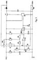
Gemäß Fig. 3 besteht die erste Referenzspannungsquelle U1 aus einem vierten, fünften und sechsten Widerstand R4, R5, R6, die hintereinander zwischen die Eingangsklemme Ue und Masse geschaltet sind, sowie einer ersten Zenerdiode ZD1, deren Anode mit Masse und dem einen Ende des sechsten Widerstands R6 verbunden ist und deren Kathode mit dem vierten und fünften Widerstand R4, R5 verbunden ist. Das andere Ende des sechsten Widerstands R6 ist mit dem nichtinvertierenden Eingang des ersten Komparators K1 (Punkt A) und dem einen Ende eines achten Widerstands R8 verbunden. Das andere Ende des achten Widerstands R8 ist über einen siebenten Widerstand R7 mit der Eingangsklemme Ue und über einen neunten Widerstand R9 mit dem Ausgang des ersten Komparators K1 verbunden. Die zweite Referenzspannungsquelle U2 besteht aus einer zweiten Zenerdiode ZD2, deren Anode mit Masse und deren Kathode mit dem invertierenden Eingang des zweiten Komparators K2 und über einen elften Widerstand R11 mit der Eingangsklemme Ue verbunden ist.3, the first reference voltage source U1 consists of a fourth, fifth and sixth resistor R4, R5, R6 connected in series between the input terminal Ue and ground are connected, and a first Zener diode ZD1, the anode of which Ground and one end of the sixth resistor R6 is connected and the Cathode is connected to the fourth and fifth resistor R4, R5. The other The end of the sixth resistor R6 is connected to the non-inverting input of the first Comparator K1 (point A) and one end of an eighth resistor R8 connected. The other end of the eighth resistor R8 is through a seventh resistor R7 with the input terminal Ue and via a ninth resistor R9 with the output of the first comparator K1. The second reference voltage source U2 consists of a second Zener diode ZD2, its anode with ground and its cathode with the inverting input of the second comparator K2 and an eleventh Resistor R11 is connected to the input terminal Ue.
Die von der ersten Referenzspannungsquelle erzeugte Referenzspannung Uref1 (Punkt A) ist die über den fünften und sechsten Widerstand R5, R6 heruntergeteilte Zenerspannung, die aus der Eingangsspannung über den vierten Widerstand R4 und die erste Zenerdiode ZD1 erzeugt wird. Sie hat, wie oben bereits erwähnt, zwei verschiedene Werte, je nach dem ob der Ausgang des ersten Komparators "low" oder "high" ist. Liegt nämlich der Ausgang des ersten Komparators K1 auf "high", wird die Spannung an Punkt A (Kippspannung) durch die heruntergeteilte Zenerspannung und der über den sechsten, siebenten und achten Widerstand R6, R7, R8 heruntergeteilten Eingangsspannung bestimmt. Liegt dagegen der Ausgang des ersten Komparators K1 auf "low", so ist der neunte Widerstand R9 der Reihenschaltung aus dem sechsten und achten Widerstand R6, R8 parallelgeschaltet. Daher wird die Spannung an Punkt A (Rückkippspannung) durch die heruntergeteilte Zenerspannung und der einerseits über den sechsten, siebenten und achten Widerstand R6, R7, R8 und andererseits den siebenten und neunten Widerstand R7, R9 heruntergeteilten Eingangsspannung bestimmt. Die Differenz zwischen der Kipp- und der Rückkippspannung ist die Hysteresespannung. Der siebente R7 und der neunte Widerstand R9 dienen gleichzeitig als Pull-up-Widerstände für den Ausgang des ersten Komparators K1.The reference voltage Uref1 (point A) is the Zener voltage divided across the fifth and sixth resistors R5, R6, that from the input voltage through the fourth resistor R4 and the first Zener diode ZD1 is generated. As mentioned above, it has two different types Values depending on whether the output of the first comparator is "low" or "high". Lies namely the output of the first comparator K1 to "high", the voltage is on Point A (breakdown voltage) by the divided Zener voltage and the over sixth, seventh and eighth resistor R6, R7, R8 divided input voltage certainly. If, on the other hand, the output of the first comparator K1 is at "low", So is the ninth resistor R9 of the series circuit from the sixth and eighth Resistor R6, R8 connected in parallel. Therefore, the voltage at point A (reverse voltage) due to the divided Zener tension and the one above the sixth, seventh and eighth resistor R6, R7, R8 and on the other hand the seventh and ninth resistor R7, R9 divided input voltage determined. The difference the hysteresis voltage is between the breakover voltage and the breakdown voltage. The seventh R7 and ninth resistor R9 also serve as pull-up resistors for the output of the first comparator K1.
Solange der Ausgang des ersten Komparators K1 "low" ist, d.h. die Ausgangsspannung des ersten Komparators K1 die Referenzspannung Uref2 der zweiten Referenzspannungsquelle U2 nicht übersteigt, bleibt der Ausgang des zweiten Komparators K2 ebenfalls auf "low". Somit wird der Treiber TR nicht angesteuert, und der steuerbare Schalter LS bleibt geöffnet. Liegt dagegen der Ausgang des ersten Komparators K1 auf "high", d.h. ist die Ausgangsspannung des ersten Komparators K1 größer als die Referenzspannung Uref2 der zweiten Referenzspannungsquelle U2, liegt auch der Ausgang des zweiten Komparators K2 auf "high". Dadurch wird der Treiber TR angesteuert, sofern nicht dem Ausgang des zweiten Komparators K2 über den Steuereingang Stop ein Abschaltsignal zugeführt ist.As long as the output of the first comparator K1 is "low", i.e. the output voltage of the first comparator K1 the reference voltage Uref2 of the second reference voltage source Does not exceed U2, the output of the second comparator K2 remains also on "low". Thus the driver TR is not activated and the controllable one Switch LS remains open. In contrast, the output of the first comparator K1 is present "high", i.e. the output voltage of the first comparator K1 is greater than that Reference voltage Uref2 of the second reference voltage source U2, is also the Output of the second comparator K2 to "high". This controls the driver TR, if not the output of the second comparator K2 via the control input Stop a shutdown signal is supplied.
Claims (8)
dadurch gekennzeichnet,
daß er eine Anordnung zur Abschaltung des Drosselwandlers bei geringer Eingangsspannung aufweist.Choke converter according to claim 1,
characterized,
that it has an arrangement for switching off the choke converter at low input voltage.
dadurch gekennzeichnet,
daß bei geringer Eingangsspannung der Ausgangswiderstand des Drosselwandlers praktisch unendlich groß ist.Choke converter according to claim 1 or 2,
characterized,
that with a low input voltage, the output resistance of the choke converter is practically infinite.
dadurch gekennzeichnet,
daß die Steuereinrichtung einen ersten Komparator (K1) mit Hysterese und eine erste Referenzspannungsquelle (U1) aufweist.Choke converter according to claim 1, 2 or 3,
characterized,
that the control device has a first comparator (K1) with hysteresis and a first reference voltage source (U1).
dadurch gekennzeichnet,
daß die von der ersten Referenzspannungsquelle (U1) gelieferte Referenzspannung (Uref1) zwei verschiedene Werte annimmt, je nach dem ob der Ausgang des ersten Komparators (K1) "low" oder "high" ist.Choke converter according to claim 4,
characterized,
that the reference voltage (Uref1) supplied by the first reference voltage source (U1) assumes two different values, depending on whether the output of the first comparator (K1) is "low" or "high".
dadurch gekennzeichnet,
daß er selbstschwingend ist.Choke converter according to claim 4 or 5,
characterized,
that it is self-swinging.
dadurch gekennzeichnet,
daß er einen Steuereingang (Stop) aufweist, über den er abgeschaltet werden kann.Choke converter according to claim 6,
characterized,
that it has a control input (stop), via which it can be switched off.
dadurch gekennzeichnet,
daß der Ausgangsstrom des Drosselwandlers sowohl in einer Leitphase als auch einer Sperrphase des steuerbaren Schalters (LS) erfaßbar ist.Choke converter according to one of the preceding claims,
characterized,
that the output current of the choke converter can be detected both in a leading phase and a blocking phase of the controllable switch (LS).
Applications Claiming Priority (2)
| Application Number | Priority Date | Filing Date | Title |
|---|---|---|---|
| DE19932379 | 1999-07-13 | ||
| DE19932379A DE19932379A1 (en) | 1999-07-13 | 1999-07-13 | Throttle converter |
Publications (2)
| Publication Number | Publication Date |
|---|---|
| EP1069672A2 true EP1069672A2 (en) | 2001-01-17 |
| EP1069672A3 EP1069672A3 (en) | 2002-02-20 |
Family
ID=7914400
Family Applications (1)
| Application Number | Title | Priority Date | Filing Date |
|---|---|---|---|
| EP00113753A Withdrawn EP1069672A3 (en) | 1999-07-13 | 2000-06-29 | Power supply with transformer choke |
Country Status (8)
| Country | Link |
|---|---|
| US (1) | US6452369B1 (en) |
| EP (1) | EP1069672A3 (en) |
| JP (1) | JP2001069751A (en) |
| KR (1) | KR20010049751A (en) |
| CN (1) | CN100392966C (en) |
| DE (1) | DE19932379A1 (en) |
| HK (1) | HK1033391A1 (en) |
| TW (1) | TW591861B (en) |
Cited By (1)
| Publication number | Priority date | Publication date | Assignee | Title |
|---|---|---|---|---|
| US9124118B2 (en) | 2011-09-16 | 2015-09-01 | Braun Gmbh | Circuit for a small electric appliance with an accumulator and method for measuring a charging current |
Families Citing this family (13)
| Publication number | Priority date | Publication date | Assignee | Title |
|---|---|---|---|---|
| ITTO20020545A1 (en) * | 2002-06-21 | 2003-12-22 | St Microelectronics Srl | CONTROL CIRCUIT IN PWM MODE FOR THE POST-REGULATION OF SWITCHING POWER SUPPLIES WITH MANY OUTPUTS |
| US7345454B2 (en) * | 2003-06-27 | 2008-03-18 | Maxwell Technologies, Inc. | Energy storage system |
| DE60320815D1 (en) | 2003-12-15 | 2008-06-19 | Dialog Semiconductor Gmbh | Current measuring circuit for DC-DC buck converter |
| JP2005287274A (en) * | 2004-03-31 | 2005-10-13 | Honda Motor Co Ltd | Step-down dc-dc converter |
| US7592793B2 (en) * | 2006-06-30 | 2009-09-22 | System General Corp. | Voltage regulator providing power from AC power source |
| JP2008129693A (en) * | 2006-11-17 | 2008-06-05 | Sanken Electric Co Ltd | Dropper type regulator |
| CN102063143B (en) * | 2010-11-10 | 2012-10-31 | 中国兵器工业集团第二一四研究所苏州研发中心 | Graded power supply management circuit |
| US9444331B2 (en) * | 2013-07-29 | 2016-09-13 | Infineon Technologies Ag | System and method for a converter circuit |
| KR101634273B1 (en) | 2014-12-11 | 2016-06-29 | 동국대학교 산학협력단 | Buck converter |
| JP5990352B1 (en) * | 2016-01-26 | 2016-09-14 | 株式会社アウルソリューション | Power supply circuit and electronic device provided with the power supply circuit |
| JP6606038B2 (en) * | 2016-09-06 | 2019-11-13 | 株式会社東芝 | Output voltage control circuit |
| US10566971B2 (en) * | 2017-08-23 | 2020-02-18 | Honeywell International Inc. | Adaptive proximity sensor |
| CN110445395A (en) * | 2019-08-13 | 2019-11-12 | 苏州格远电气有限公司 | Wide-voltage range direct current input switch power supply |
Citations (16)
| Publication number | Priority date | Publication date | Assignee | Title |
|---|---|---|---|---|
| EP0090237A2 (en) * | 1982-03-30 | 1983-10-05 | FIAR FABBRICA ITALIANA APPARECCHIATURE RADIOELETTRICHE S.p.A. | Electronic voltage control device |
| US4428015A (en) * | 1981-12-22 | 1984-01-24 | Hughes Aircraft Company | Overcurrent limiter circuit for switching regulator power supplies |
| DE3343883A1 (en) * | 1982-12-08 | 1984-06-14 | Fuji Electric Co Ltd | Method and device for two-point control of a load current |
| US4630187A (en) * | 1985-09-09 | 1986-12-16 | Sperry Corporation | Power converter with duty ratio quantization |
| FR2610149A1 (en) * | 1987-01-22 | 1988-07-29 | Telecommunications Sa | DC/DC converter with high efficiency and small load |
| US4929882A (en) * | 1987-06-23 | 1990-05-29 | National Semiconductor Corporation | Apparatus for converting DC to DC having non-feed back variable hysteretic current-mode control for maintaining approximately constant frequency |
| JPH02168864A (en) * | 1988-12-19 | 1990-06-28 | Origin Electric Co Ltd | Dc power supply device |
| EP0617501A1 (en) * | 1993-03-23 | 1994-09-28 | Linear Technology Corporation | Control circuit and method for maintaining high efficiency over broad current ranges in a switching regulator circuit |
| US5359281A (en) * | 1992-06-08 | 1994-10-25 | Motorola, Inc. | Quick-start and overvoltage protection for a switching regulator circuit |
| US5498995A (en) * | 1993-03-17 | 1996-03-12 | National Semiconductor Corporation | Short circuit frequency shift circuit for switching regulators |
| US5552695A (en) * | 1994-03-22 | 1996-09-03 | Linear Technology Corporation | Synchronously rectified buck-flyback DC to DC power converter |
| US5555148A (en) * | 1993-12-21 | 1996-09-10 | Zexel Co., Ltd. | Overvoltage protection device for capacitor externally connected to power IC |
| US5563781A (en) * | 1993-11-24 | 1996-10-08 | Integrated Technology Corporation | Dual-mode power converter |
| US5568347A (en) * | 1993-09-16 | 1996-10-22 | Nippondenso Co., Ltd. | Load driving circuit with protective circuit |
| WO1999017434A1 (en) * | 1997-09-30 | 1999-04-08 | Mitsubishi Denki Kabushiki Kaisha | Boosting active filter system and controller for boosting active filter |
| US5926383A (en) * | 1998-03-20 | 1999-07-20 | Lucent Technologies Inc. | Integrated protection circuit for a power converter and method of operation thereof |
Family Cites Families (11)
| Publication number | Priority date | Publication date | Assignee | Title |
|---|---|---|---|---|
| JPS5925533A (en) * | 1982-07-31 | 1984-02-09 | 松下電工株式会社 | Quick charging circuit |
| DE3310678C2 (en) | 1983-03-24 | 1986-09-25 | Braun Ag, 6000 Frankfurt | Circuit for regulating the output voltage of an electronic switched-mode power supply |
| JPS6032565A (en) | 1983-07-30 | 1985-02-19 | Matsushita Electric Works Ltd | Power source circuit |
| DE3921955C2 (en) * | 1989-07-04 | 2000-02-03 | Bosch Gmbh Robert | Method for generating an actuating signal for a switching regulator |
| JPH0715952A (en) | 1993-06-29 | 1995-01-17 | Toshiba Lighting & Technol Corp | Power supply, lamp lighting device and luminaire |
| EP0752748B1 (en) | 1995-06-07 | 1999-03-31 | STMicroelectronics S.r.l. | Multiple function battery charger, self-configuring as supply voltage regulator for battery powered apparatuses |
| US5734259A (en) * | 1995-09-29 | 1998-03-31 | Cherry Semiconductor Corporation | Balanced delta current method for current control in a hysteretic power supply |
| DE19612365A1 (en) | 1996-03-28 | 1997-10-02 | Telefunken Microelectron | Step=down DC voltage converter |
| WO1998024170A1 (en) | 1996-11-22 | 1998-06-04 | Siemens Aktiengesellschaft | Deep-seated free-oscillating switching regulator |
| IES80825B2 (en) | 1997-09-09 | 1999-03-10 | James Christopher Lacey | Improved dc/dc converter |
| US6111391A (en) * | 1998-09-11 | 2000-08-29 | Cullen; Richard A. | Controller for solar electric generator for recreational vehicles |
-
1999
- 1999-07-13 DE DE19932379A patent/DE19932379A1/en not_active Withdrawn
-
2000
- 2000-06-29 EP EP00113753A patent/EP1069672A3/en not_active Withdrawn
- 2000-07-03 TW TW089113129A patent/TW591861B/en not_active IP Right Cessation
- 2000-07-07 US US09/611,786 patent/US6452369B1/en not_active Expired - Fee Related
- 2000-07-10 CN CNB001098381A patent/CN100392966C/en not_active Expired - Fee Related
- 2000-07-10 KR KR1020000039207A patent/KR20010049751A/en not_active Application Discontinuation
- 2000-07-13 JP JP2000213249A patent/JP2001069751A/en active Pending
-
2001
- 2001-05-31 HK HK01103766A patent/HK1033391A1/en not_active IP Right Cessation
Patent Citations (16)
| Publication number | Priority date | Publication date | Assignee | Title |
|---|---|---|---|---|
| US4428015A (en) * | 1981-12-22 | 1984-01-24 | Hughes Aircraft Company | Overcurrent limiter circuit for switching regulator power supplies |
| EP0090237A2 (en) * | 1982-03-30 | 1983-10-05 | FIAR FABBRICA ITALIANA APPARECCHIATURE RADIOELETTRICHE S.p.A. | Electronic voltage control device |
| DE3343883A1 (en) * | 1982-12-08 | 1984-06-14 | Fuji Electric Co Ltd | Method and device for two-point control of a load current |
| US4630187A (en) * | 1985-09-09 | 1986-12-16 | Sperry Corporation | Power converter with duty ratio quantization |
| FR2610149A1 (en) * | 1987-01-22 | 1988-07-29 | Telecommunications Sa | DC/DC converter with high efficiency and small load |
| US4929882A (en) * | 1987-06-23 | 1990-05-29 | National Semiconductor Corporation | Apparatus for converting DC to DC having non-feed back variable hysteretic current-mode control for maintaining approximately constant frequency |
| JPH02168864A (en) * | 1988-12-19 | 1990-06-28 | Origin Electric Co Ltd | Dc power supply device |
| US5359281A (en) * | 1992-06-08 | 1994-10-25 | Motorola, Inc. | Quick-start and overvoltage protection for a switching regulator circuit |
| US5498995A (en) * | 1993-03-17 | 1996-03-12 | National Semiconductor Corporation | Short circuit frequency shift circuit for switching regulators |
| EP0617501A1 (en) * | 1993-03-23 | 1994-09-28 | Linear Technology Corporation | Control circuit and method for maintaining high efficiency over broad current ranges in a switching regulator circuit |
| US5568347A (en) * | 1993-09-16 | 1996-10-22 | Nippondenso Co., Ltd. | Load driving circuit with protective circuit |
| US5563781A (en) * | 1993-11-24 | 1996-10-08 | Integrated Technology Corporation | Dual-mode power converter |
| US5555148A (en) * | 1993-12-21 | 1996-09-10 | Zexel Co., Ltd. | Overvoltage protection device for capacitor externally connected to power IC |
| US5552695A (en) * | 1994-03-22 | 1996-09-03 | Linear Technology Corporation | Synchronously rectified buck-flyback DC to DC power converter |
| WO1999017434A1 (en) * | 1997-09-30 | 1999-04-08 | Mitsubishi Denki Kabushiki Kaisha | Boosting active filter system and controller for boosting active filter |
| US5926383A (en) * | 1998-03-20 | 1999-07-20 | Lucent Technologies Inc. | Integrated protection circuit for a power converter and method of operation thereof |
Non-Patent Citations (1)
| Title |
|---|
| PATENT ABSTRACTS OF JAPAN vol. 014, no. 433 (E-979), 17. September 1990 (1990-09-17) & JP 02 168864 A (ORIGIN ELECTRONIC CO.), 28. Juni 1990 (1990-06-28) * |
Cited By (1)
| Publication number | Priority date | Publication date | Assignee | Title |
|---|---|---|---|---|
| US9124118B2 (en) | 2011-09-16 | 2015-09-01 | Braun Gmbh | Circuit for a small electric appliance with an accumulator and method for measuring a charging current |
Also Published As
| Publication number | Publication date |
|---|---|
| HK1033391A1 (en) | 2001-08-24 |
| JP2001069751A (en) | 2001-03-16 |
| DE19932379A1 (en) | 2001-01-18 |
| TW591861B (en) | 2004-06-11 |
| KR20010049751A (en) | 2001-06-15 |
| CN100392966C (en) | 2008-06-04 |
| US6452369B1 (en) | 2002-09-17 |
| EP1069672A3 (en) | 2002-02-20 |
| CN1280414A (en) | 2001-01-17 |
Similar Documents
| Publication | Publication Date | Title |
|---|---|---|
| DE102008033466B4 (en) | Integral current regulator and current regulation process | |
| DE102005055160B4 (en) | Control circuit for current and voltage control in a switching power supply | |
| EP0162341B1 (en) | Electronic switching power supply | |
| DE102006061882B4 (en) | relay drive | |
| EP1069672A2 (en) | Power supply with transformer choke | |
| DE10355670B4 (en) | Method for driving a switch in a power factor correction circuit and drive circuit | |
| EP0170932A1 (en) | Circuit arrangement for supplying electrical appliances via a switching-mode controller | |
| EP1149455B1 (en) | Method and device for charging accumulators | |
| DE102004016927A1 (en) | Method for current and voltage regulation for a switching power supply | |
| WO2009059657A2 (en) | Circuit arrangement having battery cascade | |
| DE3545324A1 (en) | ELECTRONIC SWITCHING POWER SUPPLY | |
| EP2128969A2 (en) | Controller with PWM regulator | |
| EP0672314B1 (en) | Electronic combinatorial circuit component for feeding an accumulator | |
| DE60026342T2 (en) | SWITCH WITH ELECTROMAGNETIC REFRACTIVE POWER. | |
| EP0727062A1 (en) | Switched-mode power supply | |
| EP0635171B1 (en) | Switched electronic supply unit | |
| WO2001017098A1 (en) | Switched-mode mains supply unit, comprising a device for limiting the output voltage | |
| DE3300285C2 (en) | Electronic switching power supply | |
| DE19633664A1 (en) | Electrical device with energy storage | |
| EP0581989B1 (en) | Switching regulator with regulation of at least an output voltage | |
| DE10205706B4 (en) | Control circuit for a switch in a switching power supply | |
| DE10255357B4 (en) | Gleichspanungswandlerschaltung and method for DC voltage conversion | |
| DE3837561A1 (en) | DC voltage converter operating on the principle of a single-ended forward converter | |
| DE4338183A1 (en) | Circuit for controlling a charging current circuit for an accumulator | |
| DE3311737A1 (en) | Electronic switched-mode power supply |
Legal Events
| Date | Code | Title | Description |
|---|---|---|---|
| PUAI | Public reference made under article 153(3) epc to a published international application that has entered the european phase |
Free format text: ORIGINAL CODE: 0009012 |
|
| AK | Designated contracting states |
Kind code of ref document: A2 Designated state(s): AT BE CH CY DE DK ES FI FR GB GR IE IT LI LU MC NL PT SE |
|
| AX | Request for extension of the european patent |
Free format text: AL;LT;LV;MK;RO;SI |
|
| PUAL | Search report despatched |
Free format text: ORIGINAL CODE: 0009013 |
|
| RIC1 | Information provided on ipc code assigned before grant |
Free format text: 7H 02M 1/00 A, 7H 02J 7/00 B, 7H 02M 3/156 B |
|
| AK | Designated contracting states |
Kind code of ref document: A3 Designated state(s): AT BE CH CY DE DK ES FI FR GB GR IE IT LI LU MC NL PT SE |
|
| AX | Request for extension of the european patent |
Free format text: AL;LT;LV;MK;RO;SI |
|
| 17P | Request for examination filed |
Effective date: 20020717 |
|
| AKX | Designation fees paid |
Free format text: AT BE CH CY DE DK ES FI FR GB GR IE IT LI LU MC NL PT SE |
|
| 17Q | First examination report despatched |
Effective date: 20090507 |
|
| STAA | Information on the status of an ep patent application or granted ep patent |
Free format text: STATUS: THE APPLICATION IS DEEMED TO BE WITHDRAWN |
|
| 18D | Application deemed to be withdrawn |
Effective date: 20120103 |