EP1069761A2 - Method and means for producing high quality digital reflection prints from transparency images - Google Patents
Method and means for producing high quality digital reflection prints from transparency images Download PDFInfo
- Publication number
- EP1069761A2 EP1069761A2 EP00202313A EP00202313A EP1069761A2 EP 1069761 A2 EP1069761 A2 EP 1069761A2 EP 00202313 A EP00202313 A EP 00202313A EP 00202313 A EP00202313 A EP 00202313A EP 1069761 A2 EP1069761 A2 EP 1069761A2
- Authority
- EP
- European Patent Office
- Prior art keywords
- color image
- digital
- tristimulus values
- colorimetric
- digital color
- Prior art date
- Legal status (The legal status is an assumption and is not a legal conclusion. Google has not performed a legal analysis and makes no representation as to the accuracy of the status listed.)
- Withdrawn
Links
Images


Classifications
-
- H—ELECTRICITY
- H04—ELECTRIC COMMUNICATION TECHNIQUE
- H04N—PICTORIAL COMMUNICATION, e.g. TELEVISION
- H04N1/00—Scanning, transmission or reproduction of documents or the like, e.g. facsimile transmission; Details thereof
- H04N1/46—Colour picture communication systems
- H04N1/56—Processing of colour picture signals
- H04N1/60—Colour correction or control
- H04N1/6094—Colour correction or control depending on characteristics of the input medium, e.g. film type, newspaper
-
- G—PHYSICS
- G06—COMPUTING; CALCULATING OR COUNTING
- G06F—ELECTRIC DIGITAL DATA PROCESSING
- G06F18/00—Pattern recognition
Definitions
- This invention relates in general to a digital photofinishing system and more particularly to a digital photofinishing and printing system for making color reflection prints from color transparency film images.
- Patent 4,979,032 describes an apparatus, including a film scanner, a video monitor, an image processor, and an output device, to produce an image on an output medium visually matched to the image displayed on the monitor.
- U.S. Patent 5,267,030, Giorgianni et al. describes a method and means to transform images captured on film, via digitization on a film scanner, to a color metric or other space, with an output onto a variety of media and devices.
- Buhr et al (U.S. Patent 5,300,381) describes a pictorial imaging system that includes image capture on photographic film, film scanning to produce a digital image, image processing, and digital output.
- Patent 5,579,132 Takahashi, describes an image processing system devoted to storing or producing images that have "substantially the same color” or additional "aesthetic color correction" versus the original scene, based on a variety of image processing transformations of the digitized image.
- U.S. Patent 5,608,542, Krahe et al. describes a system that produces index prints based on scanning a film frame, image processing, and rendering.
- Giorgianni et al. in Digital Color Management Encoding Solutions, describes the process for converting from colorimetric tristimulus values for transparency viewing to similar values for reflection media viewing.
- a printer calibration process is described in U.S. Patent 5,053,866, S. Johnson et al.
- a method of digital print preparation comprising the steps of: producing a digital color image having colorimetric tristimulus values describing a color transparency media from a color image captured on color transparency photographic media; first transforming the digital color image having colorimetric tristimulus values describing color transparency media to a digital color image having colorimetric tristimulus values describing a reflection print; second transforming the digital color image having colorimetric tristimulus values describing a reflection print into digital code values representative of the color image for printing by a digital color printer using a combination of 1D and 3D look up tables; sharpening the transformed digital code values representative of the color image with a sharpening algorithm optimized to avoid unacceptable artifacts; and digitally printing the sharpened digital color image onto reflection media.
- the invention has the following advantages.
- a basic digital system consists of scanning, computer-based image processing, and printing.
- the following discussion outlines each of these steps, or processes, and the steps in a digital image processing chain that will lead to high quality images, for example photographic reflection prints, from transparent materials.
- Figure 1 shows digital imaging system 10, including a scanner 12 to digitize a color transparency film image, a digital image process system 14 that manipulates the digitized film image, and a digital printer 16 that renders the film image as a reflection print.
- the digital image processing system 14 is preferably a digital computer having user input and computer readable storage media, such as, magnetic, optical, solid state electronic storage devices or other physical device or medium to store a computer program.
- the digital image processing techniques described below can be stored on computer readable storage media.
- Digital printer 16 can be a laser or CRT printer, ink jet printer, thermal printer, electrophotographic printer, etc. and the reflection media is media optimized for the print technology used.
- the scanner for the production of high quality digital prints must scan a full-frame image at a resolution of sufficient density to produce images for printing at a minimum of 250dpi without interpolation. For example, image scans of at least 1000 ⁇ 1500 pixels are required to produce high quality 4 inch by 6 inch prints. It would be preferred that the scanner produce higher resolutions, such as 2000 ⁇ 3000 pixels. The higher resolution scan is preferred so that "panoramic" images can be printed with at least 1000 pixels on the short picture axis without interpolation. The higher resolution is also preferred for the preparation of 5 inch by 7 inch (5R) prints. All magnifications higher than 5R should be produced with 2000 ⁇ 3000 pixel scans.
- the scanner should deliver the digitized data to the image processing algorithm as colorimetric tristimulus values.
- a scanner that measures colorimetric tristimulus values has effective spectral responses that match, or nearly match a set of human visual color matching functions. See Figures 3A and 3B for a set of color matching function sensitivities and a second set that nearly matches, that can be transformed to the first set using a simple linear model.
- a scanner having these types of spectral responses will yield scan densities that are much easier to modify than others because of the reduced number of transforms, and the degree of transformation required to produce visual colorimetric tristimulus values.
- These types of sensitivities are also capable of scanning all type of transparency films without modification, that is, individual film types do not require specific image processing steps.
- the first step (box 20) in the process is to convert the raw scanner numbers to calibrated scanner densities.
- An appropriate matrix correction model is shown below. In this equation, N rsx is raw scanner number and D sx is corrected scanner density.
- the next process (box 22) in the scanner converts calibrated scanner densities to calibrated colorimetric densities.
- the process is implemented again with a matrix model that in this case can be up to a 3 ⁇ 10 matrix multiplication.
- a 3 ⁇ 10 matrix model is shown below.
- the output of the matrix multiplication is calibrated colorimetric density.
- D sx is calibrated scanner density and D px is calibrated colorimetric density.
- the final step (box 24) is to convert the colorimetric densities to colorimetric tristimulus values by an antilogging process.
- Another option for the conversion of the raw scanner densities to colorimetric tristimulus values is to combine all of the steps mentioned above into a sequence of 1D LUT, 3D LUT, 1D LUT, or in the simplest case, a single 3-D look-up table.
- a single 3D LUT is the preferred path to colorimetric tristimulus values producing the smallest root-mean square error.
- This section describes a process for converting the reversal transparency colorimetric tristimulus values to those for a reflection print.
- the process assumes that the scanner produces tristimulus values, or near tristimulus values that can be transformed to tristimulus values by a simple linear matrix operation. These tristimulus values represent the colorimetric values of the transparency balanced to a D5000 white point. These values are then transformed from the transparency tristimulus values to those for a reflection print, at the same white point, using the algorithm described below.
- the series of steps involved in the scan of transparencies to produce the appropriate output images is shown in Figure 2.
- the key feature of this process is to convert the transparency media color (box 24) tristimulus values, that are appropriate values for slide viewing in a darkened room, to those for print viewing (box 26).
- the two transforms are the brightness transform (box 28) and the surround transform (box 30).
- the brightness transform is a simple scaling of the tristimulus values. Later, we will describe a look up table process for this step that avoids high-light clipping problems.
- the next step is a surround transform that adjusts the final print contrast.
- the equations for the surround transform both a linear and log form, are shown below.
- the ⁇ value in the equation is selected to produce prints having a pleasing contrast to the observer.
- X , Y and Z are the colorimetric tristimulus values determined by the scanner.
- the chromatic densities are converted to linear values after the matrix adjustment.
- the transformed tristimulus values are those for a reflection print viewed under a D5000 (color temperature) illuminant.
- X , Y and Z values are the scanner measure tristimulus values and ⁇ value is an empirically determined value between 1 and 1.5.
- the color and tonescale of prints prepared using equation (5) are very similar to the color and tonescale of prints prepared using equations (3) and (4), except that there is a very slight loss of color saturation.
- the process implemented for making reflection prints is to convert the colorimetric tristimulus values to the appropriate CIELAB values using the standard equations and the tristimulus values of the D5000 illuminant reflected off of a 100% reflector.
- the CIELAB values can then be connected directly to an ICC profile for the selected output device.
- a Kodak CRT Digital Color Printer II was operated with an ICC profile.
- the CIELAB transform equations are as follows.
- One further transformation is to convert the tristimulus values to ROM colorimetric values.
- the matrix for the color space rotation and the equation for the video gamma compression are included below for reference.
- the scanner is expected to measure the tristimulus values of the slide balanced to a D5000 white point.
- the slide tristimulus values are then transformed within the scanner to the appropriate non-linear encoded ROMM values for a reflection print viewed under a D5000 illuminant.
- the transformed image data is delivered to the image data manager for subsequent processing. It will be assumed that, within the scanner and prior to delivery to the image processing system, there will be appropriate calibration and correction matrix capability, if the spectral sensitivity of the scanner is not exactly the color matching function sensitivities as shown in figure x.
- a linear matrix will be provided to transform the measured values to actual tristimulus values as if the sensitivities were color matching functions.
- a simple 3 ⁇ 3 linear correction matrix will is sufficient to provide for this transformation.
- the print rendered CIELAB values are transformed, by means of an ICC profile, to the appropriate printer code values for preparing the final print.
- a sharpening process is applied.
- the sharpening process is applied to correct for blurring effects from the scanner, printer, and any additional sharpening necessary to produce a most pleasing print appearance.
- An un-sharp masking algorithm is used for this purpose.
- D c (x) is the "sharpened" density at position x
- D(x) is the starting density at position x
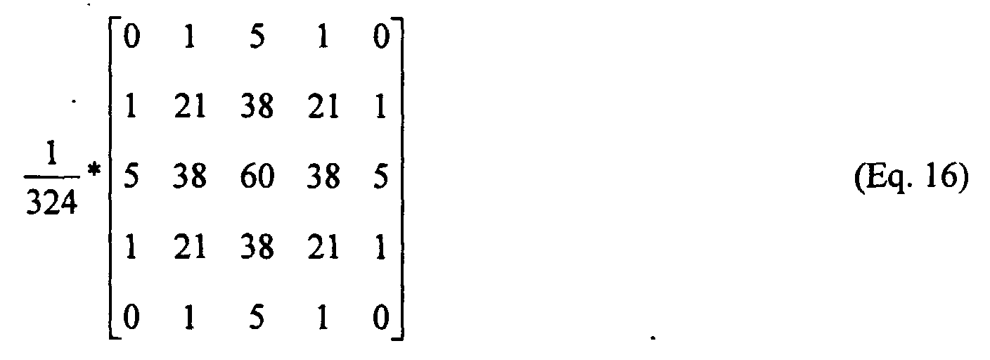
- the integral values at each pixel position are computed by convolving the image with the kernel, below (Eq. 15).
- the recommended value of ⁇ is 2.5, a value that compensates for our prototype system, and produces the most pleasing prints for sharpness. Higher values produce artifacts that give the image an artificial appearance, or "oversharpened” appearance.
- the red, green, and blue images are all sharpened to the same level.
- the encoded data is sent to a printing device that renders, or prints, the information (box 38).
- a calibration process must be operating on this device such that the code values presented to the printer will yield the expected print densities.
- the resolution of printers used for the digital print path must operate at a minimum resolution of 250 dots per inch.
- Evaluation of the printer will be done as part of the routine printer characterization process.
- a test print from a pre-processed image file will be printed, chemically processed, and measured using a reflection densitometer.
- Printer calibration will be done as part of the image processing system maintenance such that test patch density differences between measured and expected densities of less than 0.01 are obtained. The process will only require a neutral scale calibration.
- a series of uniform patches (at least 18) spanning the full range of printer code values are printed through an initial calibration LUT.
- This initial LUT must cover all those D/A count values that produce density on the print.
- the patch densities on the print are measured.
- a new calibration LUT can be calculated which should modify printing behavior according to the calibration aim.
Abstract
Description
- This invention relates in general to a digital photofinishing system and more particularly to a digital photofinishing and printing system for making color reflection prints from color transparency film images.
- Several problem areas need to be addressed when making color negative paper prints from color images on transparent media, such as film images. The object of the process is to make a pleasing reflection print from the transparent film image. The first problem is that color transparency slide images cannot be printed directly onto color negative paper. First, a color negative film intermediate image must be prepared, followed by a printing step onto color negative paper. Another alternative is to print onto special color transparency paper. These alternatives are either multi-step processes requiring considerable time to complete, or are poor in image quality because of unwanted color absorptions in the multiple sets of image dyes. Furthermore, neither process can be fully automated without considerable effort. Even if the latter processes could be automated, no options exist to correct for an inappropriate tone scale reproduction for a particular scene, or for poor sharpness in the final image, that is, there is only one film or paper option for printing all slide materials. It would be desirable to have a digital photo-processing and printing system that enables correction algorithms for the problems mentioned above.
- Methods and systems have been described that are devoted to producing pictorial images on various media and devices from scenes captured on photographic film, via scanning, to produce a digital image, image processing, and output rendering. One such system captures scenes on film, scans film to produce a digital image, digitally processes the image, and produces via a laser printer a print on AgX paper. Schreiber (U.S. Patent 4,500,919) discloses an image reproduction system that scans an image captured on film, displays the image on a video monitor, enables image processing, and produces output as an inked hardcopy. U.S. Patent 4,979,032, Alessi et al., describes an apparatus, including a film scanner, a video monitor, an image processor, and an output device, to produce an image on an output medium visually matched to the image displayed on the monitor. U.S. Patent 5,267,030, Giorgianni et al., describes a method and means to transform images captured on film, via digitization on a film scanner, to a color metric or other space, with an output onto a variety of media and devices. Buhr et al (U.S. Patent 5,300,381) describes a pictorial imaging system that includes image capture on photographic film, film scanning to produce a digital image, image processing, and digital output. U.S. Patent 5,579,132, Takahashi, describes an image processing system devoted to storing or producing images that have "substantially the same color" or additional "aesthetic color correction" versus the original scene, based on a variety of image processing transformations of the digitized image. U.S. Patent 5,608,542, Krahe et al., describes a system that produces index prints based on scanning a film frame, image processing, and rendering. Giorgianni et al., in Digital Color Management Encoding Solutions, describes the process for converting from colorimetric tristimulus values for transparency viewing to similar values for reflection media viewing. A printer calibration process is described in U.S. Patent 5,053,866, S. Johnson et al.
- All of these articles or patents describe, in one form or another, processes for obtaining more pleasing prints from a film image capture other than from the conventional optical process.
- According to the present invention, there is provided a solution to known reflection media rendering problems inherent to conventional optical or hybrid printing of transparent image media.
- According to a feature of the present invention, there is provided a method of digital print preparation comprising the steps of: producing a digital color image having colorimetric tristimulus values describing a color transparency media from a color image captured on color transparency photographic media; first transforming the digital color image having colorimetric tristimulus values describing color transparency media to a digital color image having colorimetric tristimulus values describing a reflection print; second transforming the digital color image having colorimetric tristimulus values describing a reflection print into digital code values representative of the color image for printing by a digital color printer using a combination of 1D and 3D look up tables; sharpening the transformed digital code values representative of the color image with a sharpening algorithm optimized to avoid unacceptable artifacts; and digitally printing the sharpened digital color image onto reflection media.
- The invention has the following advantages.
- 1. A pleasing reflection print is made from a color transparency film image.
- 2. Inappropriate reproduced tone scale and poor sharpness can be corrected for in a digital photofinishing operation.
- Fig. 1 is a block diagram of a digital photofinishing system incorporating the present invention.
- Fig. 2 is a flow diagram of the method of the present invention.
- Figs. 3A and 3B are graphical views useful in illustrating the present invention.
-
- A basic digital system consists of scanning, computer-based image processing, and printing. The following discussion outlines each of these steps, or processes, and the steps in a digital image processing chain that will lead to high quality images, for example photographic reflection prints, from transparent materials. Figure 1 shows
digital imaging system 10, including ascanner 12 to digitize a color transparency film image, a digitalimage process system 14 that manipulates the digitized film image, and adigital printer 16 that renders the film image as a reflection print. The digitalimage processing system 14 is preferably a digital computer having user input and computer readable storage media, such as, magnetic, optical, solid state electronic storage devices or other physical device or medium to store a computer program. The digital image processing techniques described below can be stored on computer readable storage media. Alternatively, some or all of the techniques may be incorporated into programmable gate arrays or other hard electronic devices.Digital printer 16 can be a laser or CRT printer, ink jet printer, thermal printer, electrophotographic printer, etc. and the reflection media is media optimized for the print technology used. - The scanner for the production of high quality digital prints must scan a full-frame image at a resolution of sufficient density to produce images for printing at a minimum of 250dpi without interpolation. For example, image scans of at least 1000 × 1500 pixels are required to produce high quality 4 inch by 6 inch prints. It would be preferred that the scanner produce higher resolutions, such as 2000 × 3000 pixels. The higher resolution scan is preferred so that "panoramic" images can be printed with at least 1000 pixels on the short picture axis without interpolation. The higher resolution is also preferred for the preparation of 5 inch by 7 inch (5R) prints. All magnifications higher than 5R should be produced with 2000 × 3000 pixel scans.
- Ideally, the scanner should deliver the digitized data to the image processing algorithm as colorimetric tristimulus values. A scanner that measures colorimetric tristimulus values has effective spectral responses that match, or nearly match a set of human visual color matching functions. See Figures 3A and 3B for a set of color matching function sensitivities and a second set that nearly matches, that can be transformed to the first set using a simple linear model. A scanner having these types of spectral responses will yield scan densities that are much easier to modify than others because of the reduced number of transforms, and the degree of transformation required to produce visual colorimetric tristimulus values. These types of sensitivities are also capable of scanning all type of transparency films without modification, that is, individual film types do not require specific image processing steps.
- Even though the scanner is not considered part of the digital image processing path, some manipulations of the data may be required to deliver appropriate colorimetric tristimulus values to the processing algorithm. Two key steps are: first, converting scanner densities to calibrated scanner densities, and, second, converting the calibrated scanner densities to colorimetric tristimulus values. Either matrix operations or look up tables can be used to perform these conversions.
- As shown in Fig. 2, the first step (box 20) in the process is to convert the raw scanner numbers to calibrated scanner densities. An appropriate matrix correction model is shown below.In this equation,
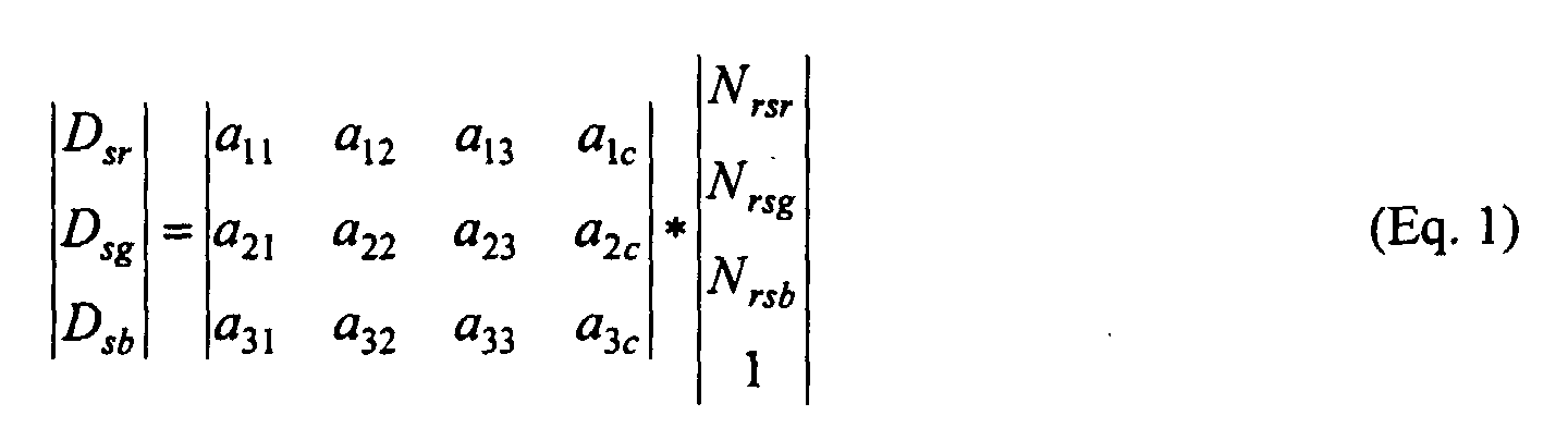
N rsx is raw scanner number andD sx is corrected scanner density. - The next process (box 22) in the scanner converts calibrated scanner densities to calibrated colorimetric densities. The process is implemented again with a matrix model that in this case can be up to a 3 × 10 matrix multiplication. An example of a 3 × 10 matrix model is shown below.
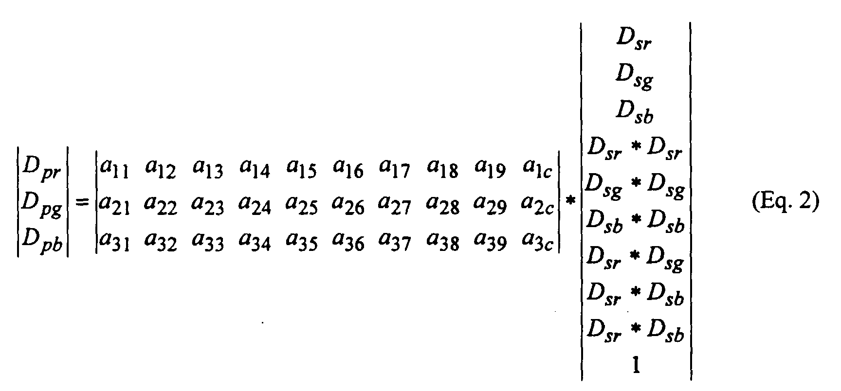
- The output of the matrix multiplication is calibrated colorimetric density.
D sx is calibrated scanner density andD px is calibrated colorimetric density. The final step (box 24) is to convert the colorimetric densities to colorimetric tristimulus values by an antilogging process. - Another option for the conversion of the raw scanner densities to colorimetric tristimulus values is to combine all of the steps mentioned above into a sequence of 1D LUT, 3D LUT, 1D LUT, or in the simplest case, a single 3-D look-up table. A single 3D LUT is the preferred path to colorimetric tristimulus values producing the smallest root-mean square error.
- This section describes a process for converting the reversal transparency colorimetric tristimulus values to those for a reflection print. The process assumes that the scanner produces tristimulus values, or near tristimulus values that can be transformed to tristimulus values by a simple linear matrix operation. These tristimulus values represent the colorimetric values of the transparency balanced to a D5000 white point. These values are then transformed from the transparency tristimulus values to those for a reflection print, at the same white point, using the algorithm described below. Three options exist at this point; these are a) use the values as is, b) convert these values to CIELAB values (see equations 8 and 9), or c) convert to ROMM values (see
equations 10 and 11) according to the publication "Reference Output Medium Metric RGB Color Space (ROMM RGB) White Paper," of the Eastman Kodak Company. The selection of the appropriate metric is based on algorithm requirements for subsequent processes, and the printer output profile selected by the user. - The series of steps involved in the scan of transparencies to produce the appropriate output images is shown in Figure 2. The key feature of this process is to convert the transparency media color (box 24) tristimulus values, that are appropriate values for slide viewing in a darkened room, to those for print viewing (box 26). The two transforms are the brightness transform (box 28) and the surround transform (box 30). The brightness transform is a simple scaling of the tristimulus values. Later, we will describe a look up table process for this step that avoids high-light clipping problems.
- The next step is a surround transform that adjusts the final print contrast. The equations for the surround transform, both a linear and log form, are shown below. The γ value in the equation is selected to produce prints having a pleasing contrast to the observer.
- If the negative log of the linear tristimulus values are determined, the equations in terms of chromatic densities (Xd , Yd and Zd ) become:
- The chromatic densities are converted to linear values after the matrix adjustment. At this point in the process, the transformed tristimulus values are those for a reflection print viewed under a D5000 (color temperature) illuminant.
- Alternatively, where there is a requirement to implement this as a ID LUT, a simpler form of the (linear) surround transform can be used:
- The color and tonescale of prints prepared using equation (5) are very similar to the color and tonescale of prints prepared using equations (3) and (4), except that there is a very slight loss of color saturation. The scaling of the tristimulus values by scale factor α to implement the brightness transform can be incorporated into these equations, as follows:
- One further step that needs to be considered in the conversion of slide tristimulus values to the tristimulus values of a reflection print under D5000 illuminant is the compression of the dynamic range of the slide tonescale (Figs. 2 - box 32). It is required that the slide tonescale be compressed such that highlight and shadow detail may be adequately represented on the final print, without clipping, whilst maintaining mid-tone contrast, according to the selected value of γ. There are a variety of possible strategies by which this may be achieved, but one of the simplest is by means of highlight and lowlight shaper LUTs. The shaper LUTs are unity (1.0) for much of their range, but incorporate curvature in either the highlight or lowlight regions of the curve to compress the highlight or shadows, respectively, in the scene. In the case of the simple linear-form equations above, the shaper LUTs can be considered as a modifier on the scaling factor, α, in the highlight and lowlight portions of the tonescale, and can therefore be incorporated into the above equations so that brightness and surround transform and tone-scale compression can be combined and implemented in a single ID LUT. More specifically, a highlight shaper LUT H, and a lowlight shaper LUT L which have been optimized for α=1 and γ=1 may be incorporated into the above equations as follows:
- The process implemented for making reflection prints is to convert the colorimetric tristimulus values to the appropriate CIELAB values using the standard equations and the tristimulus values of the D5000 illuminant reflected off of a 100% reflector. The CIELAB values can then be connected directly to an ICC profile for the selected output device. In simulations, a Kodak CRT Digital Color Printer II was operated with an ICC profile. The CIELAB transform equations are as follows.

- One further transformation is to convert the tristimulus values to ROM colorimetric values. The matrix for the color space rotation and the equation for the video gamma compression are included below for reference.
-

- where X is either R, G, or B, Imax is the maximum integer value used for the nonlinear encoding, and

- These processes can be inverted to return ROMM RGB data to XYZ values. First the non-linear encoded ROMM values to linear ROMM RGB.In this equation, X' ROMM and X ROMM are the non-linear and linear ROMM RGB values, respectively, and X is either R, G, or B. The linear ROMM RGB values are then converted to tristimulus values with the following matrix equation.


- For color transparency films, the scanner is expected to measure the tristimulus values of the slide balanced to a D5000 white point. The slide tristimulus values are then transformed within the scanner to the appropriate non-linear encoded ROMM values for a reflection print viewed under a D5000 illuminant. The transformed image data is delivered to the image data manager for subsequent processing. It will be assumed that, within the scanner and prior to delivery to the image processing system, there will be appropriate calibration and correction matrix capability, if the spectral sensitivity of the scanner is not exactly the color matching function sensitivities as shown in figure x. For example, if the scanner achieves near color matching function sensitivities, i.e., sensitivities similar to those shown in the figure without the negative lobes, then a linear matrix will be provided to transform the measured values to actual tristimulus values as if the sensitivities were color matching functions. A simple 3 × 3 linear correction matrix will is sufficient to provide for this transformation.
- As stated previously, the print rendered CIELAB values are transformed, by means of an ICC profile, to the appropriate printer code values for preparing the final print. Just prior to actually printing the image, a sharpening process is applied. The sharpening process is applied to correct for blurring effects from the scanner, printer, and any additional sharpening necessary to produce a most pleasing print appearance. An un-sharp masking algorithm is used for this purpose. The un-sharp masking equation is as follows.
- In this equation Dc(x) is the "sharpened" density at position x, D(x) is the starting density at position x, and the integral values at each pixel position are computed by convolving the image with the kernel, below (Eq. 15). The recommended value of β is 2.5, a value that compensates for our prototype system, and produces the most pleasing prints for sharpness. Higher values produce artifacts that give the image an artificial appearance, or "oversharpened" appearance.The red, green, and blue images are all sharpened to the same level.
- At this stage in the process, the encoded data is sent to a printing device that renders, or prints, the information (box 38). A calibration process must be operating on this device such that the code values presented to the printer will yield the expected print densities. The resolution of printers used for the digital print path must operate at a minimum resolution of 250 dots per inch.
- Evaluation of the printer will be done as part of the routine printer characterization process. A test print from a pre-processed image file will be printed, chemically processed, and measured using a reflection densitometer.
- Printer calibration will be done as part of the image processing system maintenance such that test patch density differences between measured and expected densities of less than 0.01 are obtained. The process will only require a neutral scale calibration.
- A series of uniform patches (at least 18) spanning the full range of printer code values are printed through an initial calibration LUT. This initial LUT must cover all those D/A count values that produce density on the print. The patch densities on the print are measured. With the initial LUT, the list of code values, respective densities of those patches, and the aim curve, a new calibration LUT can be calculated which should modify printing behavior according to the calibration aim.
Claims (7)
- A method of digital photofinishing comprising the steps of:producing a digital color image having colorimetric tristimulus values describing a color transparency media from a color image captured on color transparency media;first transforming said digital color image having colorimetric tristimulus values describing color transparency media to a digital color image having colorimetric tristimulus values describing a reflection print;second transforming said digital color image having colorimetric tristimulus values describing a reflection print into digital code values representative of said color image for printing by a digital color printer using a combination of 1D and 3D look up tables;sharpening said transformed digital code values representative of said color image with a sharpening algorithm optimized to avoid unacceptable artifacts; anddigitally printing said sharpened digital color image onto reflection media.
- The method of claim 1 wherein in said producing step, a digital color image is produced having colorimetric tristimulus values having effective spectral responses that match, or nearly match, a set of human visual color matching functions.
- The method of claim 1 wherein said producing step includes:scanning a color image captured on color transparency photographic media to produce an uncalibrated digital color image having uncalibrated scanner densities converting said uncalibrated digital color image to a calibrated digital color image having calibrated scanner densities using one of an appropriate matrix correction operation or look up tables;converting said digital color image having calibrated scanner densities to a digital color image having calibrated colorimetric densities using a matrix mode; and converting said digital color image having calibrated colorimetric densities into a digital color image having colorimetric tristimulus values using an antilogging process.
- The method of claim 1 wherein said producing step includes scanning a color image captured on color transparency photographic media to produce an uncalibrated color image signal having uncalibrated scanner densities; and using one or more 1D and/or 3D look up tables converting said digital color image having said uncalibrated scanner densities to said digital color image having colorimetric tristimulus values descriptive of a color transparency media.
- The method of claim 1 wherein said first transforming step uses a brightness transform and a surround transform.
- The method of claim 6 wherein said brightness transform uses a simple scaling of the colorimetric tristimulus values.
- The method of claim 5 including using a tone-scale compression algorithm to compress the highlight and lowlight regions of the color image.
Applications Claiming Priority (2)
| Application Number | Priority Date | Filing Date | Title |
|---|---|---|---|
| US354546 | 1999-07-15 | ||
| US09/354,546 US6424740B1 (en) | 1999-07-15 | 1999-07-15 | Method and means for producing high quality digital reflection prints from transparency images |
Publications (2)
| Publication Number | Publication Date |
|---|---|
| EP1069761A2 true EP1069761A2 (en) | 2001-01-17 |
| EP1069761A3 EP1069761A3 (en) | 2003-03-05 |
Family
ID=23393825
Family Applications (1)
| Application Number | Title | Priority Date | Filing Date |
|---|---|---|---|
| EP00202313A Withdrawn EP1069761A3 (en) | 1999-07-15 | 2000-07-03 | Method and means for producing high quality digital reflection prints from transparency images |
Country Status (3)
| Country | Link |
|---|---|
| US (1) | US6424740B1 (en) |
| EP (1) | EP1069761A3 (en) |
| JP (1) | JP2001069365A (en) |
Cited By (1)
| Publication number | Priority date | Publication date | Assignee | Title |
|---|---|---|---|---|
| EP1292118A2 (en) * | 2001-08-23 | 2003-03-12 | Eastman Kodak Company | Tone scale adjustment of digital images |
Families Citing this family (4)
| Publication number | Priority date | Publication date | Assignee | Title |
|---|---|---|---|---|
| JP4154847B2 (en) * | 2000-09-26 | 2008-09-24 | コニカミノルタビジネステクノロジーズ株式会社 | Image processing apparatus, image processing method, and computer-readable recording medium storing image processing program |
| US6985253B2 (en) * | 2000-12-28 | 2006-01-10 | Eastman Kodak Company | Processing film images for digital cinema |
| US7702146B2 (en) * | 2004-05-06 | 2010-04-20 | Canon Kabushiki Kaisha | Color characterization using color value clipping |
| US20100245381A1 (en) * | 2009-03-28 | 2010-09-30 | Ramin Samadani | Color gamut mapping |
Citations (5)
| Publication number | Priority date | Publication date | Assignee | Title |
|---|---|---|---|---|
| US4500919A (en) * | 1982-05-04 | 1985-02-19 | Massachusetts Institute Of Technology | Color reproduction system |
| US4930009A (en) * | 1987-06-19 | 1990-05-29 | Fuji Photo Film Co., Ltd. | Method of making a print of color slide |
| EP0624028A1 (en) * | 1993-05-07 | 1994-11-09 | Eastman Kodak Company | Method and associated apparatus which achieve imaging device/media compatibility and color appearance matching |
| US5754184A (en) * | 1993-01-06 | 1998-05-19 | Eastman Kodak Company | Digital color system and method which provides a visual match across different input and output viewing conditions |
| US20020159098A1 (en) * | 2001-03-16 | 2002-10-31 | Larry Kleiman | Hyperspectral system for capturing graphical images |
Family Cites Families (10)
| Publication number | Priority date | Publication date | Assignee | Title |
|---|---|---|---|---|
| US4979032A (en) | 1988-12-27 | 1990-12-18 | Eastman Kodak Company | Color imaging apparatus producing on various image receptive materials a visually matched hard copy reproduction of a video image displayed |
| US5053866A (en) | 1989-08-02 | 1991-10-01 | Eastman Kodak Company | Method and an associated apparatus for calibrating a color digital hardcopy device |
| US5267030A (en) | 1989-12-22 | 1993-11-30 | Eastman Kodak Company | Method and associated apparatus for forming image data metrics which achieve media compatibility for subsequent imaging application |
| DE69319979T2 (en) | 1992-09-08 | 1998-12-10 | Fuji Photo Film Co Ltd | Image processing system and method for faithful reproduction of the colors of objects on negative film |
| US5300381A (en) | 1992-09-24 | 1994-04-05 | Eastman Kodak Company | Color image reproduction of scenes with preferential tone mapping |
| US5528339A (en) * | 1994-08-26 | 1996-06-18 | Eastman Kodak Company | Color image reproduction of scenes with color enhancement and preferential tone mapping |
| US5881209A (en) * | 1994-09-13 | 1999-03-09 | Apple Computer, Inc. | Method and system for automatically generating printer profiles |
| US5608542A (en) | 1995-03-31 | 1997-03-04 | Eastman Kodak Company | Formatted digital index print system and method |
| JP3907783B2 (en) * | 1996-12-12 | 2007-04-18 | 富士フイルム株式会社 | Color conversion method |
| JP3639405B2 (en) * | 1997-03-07 | 2005-04-20 | 東洋インキ製造株式会社 | Color gamut compression method and apparatus |
-
1999
- 1999-07-15 US US09/354,546 patent/US6424740B1/en not_active Expired - Fee Related
-
2000
- 2000-06-08 JP JP2000171809A patent/JP2001069365A/en active Pending
- 2000-07-03 EP EP00202313A patent/EP1069761A3/en not_active Withdrawn
Patent Citations (5)
| Publication number | Priority date | Publication date | Assignee | Title |
|---|---|---|---|---|
| US4500919A (en) * | 1982-05-04 | 1985-02-19 | Massachusetts Institute Of Technology | Color reproduction system |
| US4930009A (en) * | 1987-06-19 | 1990-05-29 | Fuji Photo Film Co., Ltd. | Method of making a print of color slide |
| US5754184A (en) * | 1993-01-06 | 1998-05-19 | Eastman Kodak Company | Digital color system and method which provides a visual match across different input and output viewing conditions |
| EP0624028A1 (en) * | 1993-05-07 | 1994-11-09 | Eastman Kodak Company | Method and associated apparatus which achieve imaging device/media compatibility and color appearance matching |
| US20020159098A1 (en) * | 2001-03-16 | 2002-10-31 | Larry Kleiman | Hyperspectral system for capturing graphical images |
Cited By (2)
| Publication number | Priority date | Publication date | Assignee | Title |
|---|---|---|---|---|
| EP1292118A2 (en) * | 2001-08-23 | 2003-03-12 | Eastman Kodak Company | Tone scale adjustment of digital images |
| EP1292118A3 (en) * | 2001-08-23 | 2004-05-26 | Eastman Kodak Company | Tone scale adjustment of digital images |
Also Published As
| Publication number | Publication date |
|---|---|
| JP2001069365A (en) | 2001-03-16 |
| EP1069761A3 (en) | 2003-03-05 |
| US6424740B1 (en) | 2002-07-23 |
Similar Documents
| Publication | Publication Date | Title |
|---|---|---|
| EP0961484B1 (en) | Digital photofinishing system with digital image processing | |
| US6975437B2 (en) | Method, apparatus and recording medium for color correction | |
| EP1139653B1 (en) | Color image reproduction of scenes with preferential color mapping | |
| US6243133B1 (en) | Method for automatic scene balance of digital images | |
| Vrhel et al. | Color device calibration: A mathematical formulation | |
| US5363318A (en) | Method and apparatus for adaptive color characterization and calibration | |
| US4992862A (en) | Color conversion display apparatus and method | |
| EP1014687A2 (en) | Correcting exposure and tone scale of digital images captured by an image capture device | |
| EP1158779A2 (en) | Color image reproduction of scenes with preferential color mapping and scene-dependent tone scaling | |
| JPH07231393A (en) | Picture reproducing device | |
| JPH0715612A (en) | Device and method for encoding color | |
| JP4174703B2 (en) | Spectrum / color reproduction system | |
| EP0961483B1 (en) | Digital photofinishing system with digital image processing | |
| EP0961486B1 (en) | Digital photofinishing system with digital image processing | |
| JP4197276B2 (en) | Image processing apparatus, image reading apparatus, image forming apparatus, and image processing method | |
| US20080130023A1 (en) | Color Reproduction on Translucent or Transparent Media | |
| US7136187B1 (en) | Color correcting relation extracting method and color correction method | |
| US5995654A (en) | Digital photofinishing system including scene balance and image sharpening digital image processing | |
| US20040042681A1 (en) | Image processing method, image processing apparatus, image recording apparatus, program, and recording medium | |
| US6424740B1 (en) | Method and means for producing high quality digital reflection prints from transparency images | |
| Berns et al. | Color managing the third edition of Billmeyer and Saltzman's Principles of Color Technology | |
| JP2002247394A (en) | Method of preparing color converting rule, method of converting color, and colored image forming device | |
| EP0758181B1 (en) | A method for producing an original image data adjusting table for a proof printing system | |
| CA2117030C (en) | Color reproducing method used in an image data processing system comprising independent input and output devices | |
| US7369273B2 (en) | Grayscale mistracking correction for color-positive transparency film elements |
Legal Events
| Date | Code | Title | Description |
|---|---|---|---|
| PUAI | Public reference made under article 153(3) epc to a published international application that has entered the european phase |
Free format text: ORIGINAL CODE: 0009012 |
|
| AK | Designated contracting states |
Kind code of ref document: A2 Designated state(s): AT BE CH CY DE DK ES FI FR GB GR IE IT LI LU MC NL PT SE |
|
| AX | Request for extension of the european patent |
Free format text: AL;LT;LV;MK;RO;SI |
|
| PUAL | Search report despatched |
Free format text: ORIGINAL CODE: 0009013 |
|
| AK | Designated contracting states |
Kind code of ref document: A3 Designated state(s): AT BE CH CY DE DK ES FI FR GB GR IE IT LI LU MC NL PT SE Designated state(s): AT BE CH CY DE DK ES FI FR GB GR IE IT LI LU MC NL PT SE |
|
| AX | Request for extension of the european patent |
Extension state: AL LT LV MK RO SI |
|
| 17P | Request for examination filed |
Effective date: 20030731 |
|
| AKX | Designation fees paid |
Designated state(s): DE FR GB |
|
| 17Q | First examination report despatched |
Effective date: 20050531 |
|
| STAA | Information on the status of an ep patent application or granted ep patent |
Free format text: STATUS: THE APPLICATION IS DEEMED TO BE WITHDRAWN |
|
| 18D | Application deemed to be withdrawn |
Effective date: 20051011 |