EP1071288A2 - Video controller - Google Patents
Video controller Download PDFInfo
- Publication number
- EP1071288A2 EP1071288A2 EP00305858A EP00305858A EP1071288A2 EP 1071288 A2 EP1071288 A2 EP 1071288A2 EP 00305858 A EP00305858 A EP 00305858A EP 00305858 A EP00305858 A EP 00305858A EP 1071288 A2 EP1071288 A2 EP 1071288A2
- Authority
- EP
- European Patent Office
- Prior art keywords
- video
- channel
- channels
- supplied
- signals
- Prior art date
- Legal status (The legal status is an assumption and is not a legal conclusion. Google has not performed a legal analysis and makes no representation as to the accuracy of the status listed.)
- Granted
Links
Images


Classifications
-
- H—ELECTRICITY
- H04—ELECTRIC COMMUNICATION TECHNIQUE
- H04N—PICTORIAL COMMUNICATION, e.g. TELEVISION
- H04N21/00—Selective content distribution, e.g. interactive television or video on demand [VOD]
- H04N21/40—Client devices specifically adapted for the reception of or interaction with content, e.g. set-top-box [STB]; Operations thereof
- H04N21/41—Structure of client; Structure of client peripherals
- H04N21/422—Input-only peripherals, i.e. input devices connected to specially adapted client devices, e.g. global positioning system [GPS]
- H04N21/42204—User interfaces specially adapted for controlling a client device through a remote control device; Remote control devices therefor
-
- H—ELECTRICITY
- H04—ELECTRIC COMMUNICATION TECHNIQUE
- H04N—PICTORIAL COMMUNICATION, e.g. TELEVISION
- H04N21/00—Selective content distribution, e.g. interactive television or video on demand [VOD]
- H04N21/40—Client devices specifically adapted for the reception of or interaction with content, e.g. set-top-box [STB]; Operations thereof
- H04N21/43—Processing of content or additional data, e.g. demultiplexing additional data from a digital video stream; Elementary client operations, e.g. monitoring of home network or synchronising decoder's clock; Client middleware
- H04N21/438—Interfacing the downstream path of the transmission network originating from a server, e.g. retrieving MPEG packets from an IP network
- H04N21/4383—Accessing a communication channel
-
- H—ELECTRICITY
- H04—ELECTRIC COMMUNICATION TECHNIQUE
- H04N—PICTORIAL COMMUNICATION, e.g. TELEVISION
- H04N21/00—Selective content distribution, e.g. interactive television or video on demand [VOD]
- H04N21/40—Client devices specifically adapted for the reception of or interaction with content, e.g. set-top-box [STB]; Operations thereof
- H04N21/43—Processing of content or additional data, e.g. demultiplexing additional data from a digital video stream; Elementary client operations, e.g. monitoring of home network or synchronising decoder's clock; Client middleware
- H04N21/443—OS processes, e.g. booting an STB, implementing a Java virtual machine in an STB or power management in an STB
- H04N21/4436—Power management, e.g. shutting down unused components of the receiver
-
- H—ELECTRICITY
- H04—ELECTRIC COMMUNICATION TECHNIQUE
- H04N—PICTORIAL COMMUNICATION, e.g. TELEVISION
- H04N21/00—Selective content distribution, e.g. interactive television or video on demand [VOD]
- H04N21/60—Network structure or processes for video distribution between server and client or between remote clients; Control signalling between clients, server and network components; Transmission of management data between server and client, e.g. sending from server to client commands for recording incoming content stream; Communication details between server and client
- H04N21/65—Transmission of management data between client and server
- H04N21/654—Transmission by server directed to the client
- H04N21/6543—Transmission by server directed to the client for forcing some client operations, e.g. recording
-
- H—ELECTRICITY
- H04—ELECTRIC COMMUNICATION TECHNIQUE
- H04N—PICTORIAL COMMUNICATION, e.g. TELEVISION
- H04N7/00—Television systems
- H04N7/16—Analogue secrecy systems; Analogue subscription systems
- H04N7/173—Analogue secrecy systems; Analogue subscription systems with two-way working, e.g. subscriber sending a programme selection signal
- H04N7/17309—Transmission or handling of upstream communications
Definitions
- This invention relates to the distribution of video signals and, more particularly, to controlling the distribution of the video signals.
- Video signals to one or more outlets at a location is now typically realized by the use of coaxial cable (COAX).
- COAX coaxial cable
- video terminals connected to the one or more outlets are for the most part analog television sets (TVs).
- digital broadband access systems e.g., cable modem, fiber-to-the-home, or the like, which would deliver MPEG2 (Motion Picture Experts Group 2) standard digital video signals. These digital signals must be converted to analog video signals consistent with available TVs, and with COAX signals expected by cable ready TVs.
- MPEG2 Motion Picture Experts Group 2
- a known approach is the use of an individual set-top-box for each TV, which includes a MPEG2 decoder, a digital-to-analog (D/A) converter, a NTSC (National Television Systems Committee) encoder and a frequency up-converter to deliver the video at the frequency of a selected channel.
- D/A digital-to-analog
- NTSC National Television Systems Committee
- a frequency up-converter to deliver the video at the frequency of a selected channel.
- the use of an individual set-top-box per TV assumes the availability of all desired video channels at an input of each of the set-top-boxes.
- the need to deliver all channels to each set-top-box is an inefficient use of the broadband access system.
- the use of such individual set-top-boxes is inefficient, cumbersome and costly. The inefficiency results because typically only a few of the TVs and associated set-top-boxes are active at any given time.
- the centralized controller includes one or more MPEG2 decoders, the number of which depends on a desired number of active TVs to be used in viewing different video programs on different channels, and one or more wireless, e.g., radio frequency (RF) or infra red, communications links to television controllers, i.e., remote control units, associated on a one-to-one basis with the desired number of TVs.
- MPEG2 decoders the number of which depends on a desired number of active TVs to be used in viewing different video programs on different channels
- wireless e.g., radio frequency (RF) or infra red
- channel selection for each of the one or more TVs is typically communicated up-stream from the centralized controller to a video server and a video services controller, therein.
- the video server only transmits the selected channels to the local centralized video controller.
- the video channel is already being supplied from the video server to an optical line terminal and, specifically, to an optical line card to which the requesting centralized controller is connected to, there is no need to communicate the channel request to the video server.
- the optical line terminal simply supplies the requested channel via an optical line card to the additional requesting centralized controller and, in turn, to the requesting TV.
- each of the one or more active TVs is assigned one of a plurality of program units included in the centralized controller, and is switched to a video channel that is supplied an analog video signal by the program unit.
- each program unit includes a broadband asynchronous transfer mode (ATM) virtual channel (VC) filter, a MPEG2 decoder, a NTSC encoder and a frequency up-converter.
- ATM asynchronous transfer mode
- the MPEG2 decoder decodes a video signal supplied via the VC and supplies the analog version of the decoded video signal as its output.
- the analog video signal is NTSC encoded and up-converted to a fixed video channel.
- the video channel designation corresponds to the assigned MPEG2 decoder and is specified by the centralized video controller.
- the video channel number is transmitted to the TV remote control unit via a first wireless link and, then, supplied to the TV tuner via an infra red (IR) wireless link. Additionally, the remote control unit communicates channel selections via the first wireless link to the centralized video controller that, in this example, passes the channel selections to a video services controller in a video server using an up-stream communications link.
- the up-stream communications link is a broadband ATM VC.
- the video server transmits the selected channel to the centralized video controller using a down-stream communications link.
- the down-stream link is a constant bit rate (CBR) ATM VC.
- the digital video signal is supplied to the centralized video controller as a continuous stream of ATM cells, while the up-stream communications is transmitted as bursts.
- a specific VC is statically assigned to each conventional broadcast video channel and other VCs are dynamically assigned for other video services, for example, video-on-demand, or the like. If the program units are all in use supplying video channels to active TVs, additional TVs can tune to any of the supplied video channels but they do not have any "program' selection capability.
- the up-converter included in each program unit is frequency agile.
- a video channel selected via the remote control unit is communicated to the centralized video control unit via the first wireless link and is transmitted up-stream to the video server and the video services controller, therein.
- the selected video program channel is also supplied to the TV tuner via the IR wireless link.
- the MPEG2 decoded video signal is transmitted on the selected program channel. This is realized by dynamically controlling the channel that the video signal is up-converted to by the agile up-converter. Indeed, as the channel selections are made, the associated remote control unit transmits the channel designation to both the TV tuner and the centralized video controller using the IR wireless link and the first wireless link, respectively.
- the up-converter has a fixed frequency, i.e., video channel, which is assigned to an associated MPEG2 decoder.
- FIG. 1 shows, in simplified block diagram form, a video distribution system employing an embodiment of the invention.
- network 100 including video server 101 which supplies down-stream video signals to broadband network 102, in response to an up-stream communication including a selection message.
- Broadband network 102 supplies the communications signals to and from optical line terminal 103.
- optical line circuit (OLC) 104 interfaces to an optical fiber line.
- the optical fiber line is, for example, a power splitting passive optical network (PSPON) fiber including optical fibers 110 and 111 on which optical signals are transmitted using coarse wavelength division multiplexing.
- PSPON power splitting passive optical network
- the PSPON fibers 110 may be split via passive splitter 105 into a prescribed number of optical fibers 111, for example, 32 fibers 111, thereby interfacing via associated ONUs 106 with 32 locations.
- OLT 103 serves one or more OLCs 104, namely, 104-1 through 104-Z, coupled to a corresponding number of fiber lines, namely, 110-1 through 110-Z, respectively, and that an OLC 104 serves one or more ONUs 106 via optical fibers 111-1 through 111-W.
- the down-stream transmission of video signals is in asynchronous transfer mode (ATM) cells via time division multiplex (TDM), while up-stream transmission of communication is via time division multiple access (TDMA), and both down-stream and up-stream communications is at 155.52 Mb/sec.
- ATM asynchronous transfer mode
- TDMA time division multiple access
- Efficient TDMA communications in the up-stream direction requires all optical network units (ONUs) 106 to have equal loop delay in relationship to their associated OLC 104. This is realized by employing a ranging procedure that is executed when each ONU 106 associated with a particular OLC 104 is installed, moved, returned to service, or the like. This is realized by employed a ranging procedure that is executed when each ONU 106 is installed.
- the ranging procedure defines an artificial delay that when added to the transmission loop delay of an ONU 106 yields the required common loop delay.
- Such ranging arrangements are known in the art. However, a preferred ranging arrangement is described in co-pending United States Patent application Serial No. (D. E. Blahut-P. Magill Case 46-20) filed concurrently herewith and assigned to the assignee of this application.
- OLT 103 is a special ATM switch including a traditional ATM fabric and input/output (I/O) ports.
- I/O input/output
- two types of I/O boards are required, namely, standard SONET (synchronous optical network) boards, e.g., OC-12 units, and OLC units 104.
- Video signals received from OLT 103 as ATM cells from one or more SONET boards are distributed to the OLC units 104. Because of this, up-stream channel select messages being sent to video services controller 202 in video server 101 are intercepted within the OLT 103, which accumulates the number of viewers of each video program that is OLT 103 wide. Only channel (program) selections that are not available within presently received SONET VCs are passed on to the video services controller 202 in video server 101.
- program program
- each of OLC units 104 includes, in this example, a CPU and memory (not shown) that may be a microprocessor with memory.
- Optical network unit (ONU) 106 terminates the PSPON fiber 110 via an associated PSPON optical fiber 111, and provides appropriate interfaces, in this example, to one or more television sets (TVs) 107-1 through 107-N.
- TVs 107-1 through 107-N has an associated one of remote control (RC) units 108-1 through 108-N, respectively.
- RC remote control
- Network 100 supplies, for example, via one or more video services controller 202 in video server 101 in response to specific program requests, conventional broadcast TV programs, programs similar to those supplied via cable TV providers, satellite TV providers, video on demand and the like. Procedures for requesting and transmitting video programs are described in greater detail below.
- a residential video subsystem includes an ONU 106 and one or more TVs 107 and associated RC units 108.
- ONU 106 and TVs 107 are interconnected via coaxial (COAX) cable.
- COAX coaxial
- FIG. 2 is a simplified block diagram of video server 101 employed in the system of FIG. 1. Specifically, shown are video storage server 201, video services controller 202 and a block of MPEG2 video encoders 203-1 through 203-Y. Broadcast video signals are received via inputs 204-1 through 204-Y and supplied on a one-to-one basis to MPEG2 video encoders 203-1 through 203-Y, respectively, where they are digitally encoded and compressed in now well known fashion. Thereafter, the digitally encoded MPEG2 video signals are supplied to video storage server 201. As described below in relationship to FIG. 3, video storage server 201 stores the digitally encoded MPEG2 video signals to be transmitted to subscribers.
- Video signals may be prestored in video storage server 201 to support, for example, video-on-demand, or directed advertisement insertion.
- the transmission of the digitally encoded MPEG2 video signals is in response to control signals from a subscriber and supplied, in this example, via TDMA in ATM cells over transmission link 109 to video server 101 and, therein, via 207 to video services controller 202.
- video services controller 202 supplies/and or receives control signals to and/or from video storage server 201.
- video storage server 201 supplies appropriate video signals including advertisements during commercial intervals or in accordance with the service being provided to one or more subscribers.
- the video signals are included in ATM cells and formatted as an ATM signal for transmission. Thereafter, the ATM formatted signal is supplied as an output from video server 201 via 206 to bi-directional transmission link 109.
- FIG. 2 shows a block diagram of the video server 101 consisting of a bank of MPEG2 video encoders 203, a video storage server 201, and a video services controller 202.
- all encoded broadcast video signals are delivered through the video storage server 201. Therefore, each digital video signal stream is written to the video storage server 201 in real time, as well as, read from that server 201 in near real time.
- a read memory pointer in video services controller 202 just simply follows the write pointer, also in controller 202, by some non-zero amount. It is worth noting that the delay between the writing and the reading of a video signal stream is not important. In fact, one possible advanced video service that immediately follows is a "delayed broadcast on demand".
- the video service controller 202 manages the writing and reading of all video signal streams, providing independent address information for each digital video signal stream that is written and/or read, as well as ATM virtual circuit (VC) information.
- control operations e.g., "pause"
- data are written in blocks that are divisible by 48.
- ATM cells are formatted as part of the server's I/O operations and an ATM formatted signal is supplied as an output via 206.
- FIG. 3 shows, in simplified block diagram form, details of a centralized video controller, namely, one implementation of ONU 106, employing an embodiment of the invention that may be employed in the system 100 of FIG. 1.
- ONU 106 includes at least one radio frequency (RF) receiver 301, CPU 302, one or more program units 303-1 through 303-M and RF combiner 309. It is noted that there must be at least "M" RF receivers 301 corresponding to the number "M" of program units 303.
- the number of program units 303 i.e., M, defines the number of video programs that can be viewed simultaneously by multiple TVs 107 within a location, e.g., a home.
- RF receiver 301 receives RF signals including control messages from a remote control unit associated with a TV 107 (FIG. 1). This may be realized by employing a RF transmitter in the TV remote control unit, described below in conjunction with FIG. 4, and a RF receiver, both of a type used in a wireless, i.e., cordless, telephone, now well known in the art. Note that there may be a plurality of TVs and a corresponding plurality of remote control units. ONU 106 would include as many RF receivers as there are remote control units. RF control messages include, for example, the associated remote control unit identity (ID) and a selected channel number.
- ID the associated remote control unit identity
- Other control messages include, in addition to the remote control ID, for example, an indication that an associated TV has been either powered ON or powered OFF.
- the information received in the RF control message is supplied to CPU 302.
- CPU 302 is, for example, a microprocessor including memory.
- CPU 302 receives a RF transmission from a previously inactive remote control unit 108, it assigns one of program units 303 to the TV 107 associated with the remote control unit 108, it writes the VC corresponding to the received channel number into register 304 and determines that VC through use of a look-up table. It maintains a count of how many active TVs 107 are tuned to the selected program and it stores the selected channel for this TV 107 in a lookup table.
- CPU 302 transmits a message up-stream to video server 101 and video services controller 202, therein, requesting the transmission of the selected video program.
- the selected program is transmitted down-stream in ATM cells on the virtual circuit (VC) identified by the selected program channel number and received at the selected program unit 303, in this example, program unit 303-1.
- the selected channel number's VC and channel number are supplied to virtual circuit (VC) filter 305 and to agile up-converter 308, respectfully, to tune them to the selected program channel.
- the selected video program is received at ONU 106 and supplied to VC filter 305 as a sequence of ATM cells.
- VC filter 305 filters the received signal to obtain the selected program channel signal as a MPEG2 digital video signal, i.e., a compressed digital video signal, that is supplied to MPEG2 decoder 306.
- MPEG2 digital decoder 306 yields an analog version of the selected video channel, which is supplied to NTSC encoder 307 where it is encoded.
- the NTSC encoded signal is then supplied to up-converter 308, where the video signal is frequency converted to the selected standard video channel frequency, i.e., 6 MHz channel.
- up-converter 308 is a so-called agile up-converter that adjusts its frequency to the frequency of the supplied program channel number.
- the resulting channel signal is supplied to RF combiner 309 where it is combined with channel signals from others of program units 303, if any, and transmitting via COAX to one or more TVs 107, i.e., all the TVs, at the location, e.g., a home.
- FIG. 4 shows, in simplified block diagram form, details of a remote control unit 108 (FIG. 1), including an embodiment of the invention, that may be employed with the video controller of FIG. 3. Shown is button pad 401 for keying a desired channel number that is supplied to RF transmitter 402 and infra red (IR) transmitter 403.
- RF transmitter 402 transmits to ONU 106 a RF signal, for example, a packet containing a message including the remote unit ID and the selected channel number.
- IR transmitter 403 transmits an infra red signal in well known fashion to an associated TV 107-1.
- a user turns ON the TV 107-1 by pressing an "ON" button on button pad 401 of remote control 108-1.
- a wireless IR signal transmission is made via IR transmitter 403 to the TV 107-1, which turns its power ON in usual fashion.
- a wireless RF transmission is made via RF transmitter 402 of a control packet containing the identification (ID) of the remote control unit 108-1 and a power ON command.
- ONU 106 (FIG. 3) via CPU 302 retains knowledge of the channel that each TV 107 at the location was tuned to when the particular TV was last turned OFF, which is the channel that the TV should be initially tuned to when it is turned ON. This is so the TV 107 closely mimics current conventional analog video delivery techniques.
- ONU 106 utilizes this retained information to perform two operations. First, if the previously viewed channel is not being viewed currently by another TV 107, ONU 106 employs the information to insure that a MPEG2 decoder 306, if one is available, and associated circuitry is assigned to the retained channel, i.e., to the corresponding ATM VC. Second, ONU 106 sends a control packet up-stream to video server 101 (FIG. 1) and, therein, to video services controller 202, requesting that a program on the desired previously viewed channel be transmitted to the ONU 106. Assuming that a MPEG2 decoder 306 is available, the associated TV now displays the program on the channel that the TV was last tuned to prior to being turned OFF.
- ONU 106 appropriately formulates and passes up-stream messages via CPU 302 to the video server 101 and, therein, to a remote video services controller 202 requesting that the transmitted digital video program for that PSPON 110 and 111 be appropriately changed. Also, if not already assigned, a MPEG2 decoder 306 and associated circuitry are assigned.
- CPU 302 retains information regarding the number of TVs 107 that are viewing each requested video program. When a requested video program is no longer being viewed by any of TVs 107, CPU 302 transmits an up-stream message to video server 101 and, therein, to video services controller 202 indicating that the video program is no longer being viewed.
- the system operation might be different. For example, if video-on-demand (VOD) is selected, the user is assigned an otherwise unused channel for point-to-point delivery of the interactive video preview/select program.
- the MPEG2 decoder 306, for this example, is dedicated to that TV 107, remote control 108 pair. Other TVs can also view that video, but its interactive control is disabled, as long as, the TV 107 associated with the initiating remote control 108 is still viewing the program.
- the initiating remote control 108 is employed to select a different program, control of the VOD is relinquished and the next remote control 108 that attempts an interactive control function, e.g., pause, is assumed to be the initiating remote control 108.
- other interactive TV applications can be accessed. For some interactive applications, such as games, multiple controlling remote controls 108 are appropriate. In such a situation, however, the application would typically distinguish between the active remote controls 108.
- CPU 302 (FIG. 3) receives a RF transmission from a previously inactive remote control unit 108, it responds as follows:
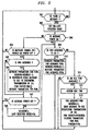
- FIG. 5 is a flow chart illustrating steps in the operational process of the centralized video controller of FIG. 3, namely, ONU 106 including agile up-converter 308, in the system of FIG. 1.
- parameters for each of program units (PUNs) 303 in ONU 106 include number of viewers, PUN status and the program channel (CH).
- ONU 106 waits to receive a RF message from a remote control unit 108.
- step 501 tests to determine if a message is being received. If the test result in step 501 is NO, step 501 just repeats until the test result is YES and a message has been received that yields a YES result.
- step 502 causes the program channel (CH) to be set to the last selected channel CH (N), where "N" corresponds to the remote control unit 108.
- PUN program unit
- CH program channel
- FIG. 6 shows, in simplified block diagram form, details of another centralized video controller employing an embodiment of the invention that may be employed in the system of FIG. 1.
- ONU 106 includes at least one radio frequency (RF) receiver 301 and at least one associated RF transmitter 603, CPU 302, one or more program units 601-1 through 601-M and RF combiner 309. It is noted that there are as many RF transceivers including a receiver 301 and transmitter 603, as there are remote units 108.
- the number of program units 601, i.e., M defines the number of video programs that can be simultaneously viewed by multiple TVs within a location, e.g., a home.
- RF receiver 301 receives RF signals including control messages from a remote control unit associated with a TV 107 (FIG. 1).
- This may be realized by employing a RF transmitter 402 in the TV 107 remote control unit 108, described below in conjunction with FIG. 7, and a RF receiver 301, both of the type used in a wireless telephone, which are well known in the art.
- each RF receiver 301 has an associated RF transmitter 603 for transmitting a "wireless" RF signal to an associated remote control unit 108 including the fixed channel number that up-converter 602 is tuned to, as described below.
- there may be a plurality of TVs 107 and a corresponding plurality of remote control units 108.
- ONU 106 would include as many RF receivers and associated RF transmitters, as there are remote control units 108.
- the received RF control message includes, for example, the associated remote control unit identity (ID) and a selected channel number.
- Other control messages include, in addition to the remote control ID, an indication of an associated TV being either powered ON or Powered OFF.
- the information received in the RF control message is supplied to CPU 302.
- CPU 302 is, for example, a microprocessor including memory.
- CPU 302 retains a look-up table containing information indicating the last selected program channel number for each of TVs 107, including those of TVs 107 that are currently inactive.
- CPU 302 When CPU 302 receives a RF transmission from a previously inactive remote control unit 108, it assigns one of program units 601 to the TV associated with the remote control unit, it writes the last selected program channel number into register 304, it writes the RF video program channel number being used by the assigned program unit 601 to RF transmitter 603 which, in turn, transmits the RF signal to the RF receiver in an associated remote control unit 108, it maintains a count of how many active TVs are tuned to the selected channel number and it stores the selected channel number for this TV 107 in a lookup table.
- CPU 302 transmits a message up-stream to video server 101 and a video services controller 202, therein, requesting the transmission of the selected channel.
- the selected channel is transmitted down-stream in ATM cells on the virtual circuit (VC) identified by the selected program channel number and received at the selected program unit 601, in this example, program unit 601-1.
- the selected channel number's VC is supplied to virtual circuit (VC) filter 305 to tune it to the selected program channel.
- the selected video program channel is received at ONU 106 and supplied to VC filter 305 as a sequence of ATM cells.
- VC filter 305 obtains the selected program channel signal as a MPEG2 digital video signal that is supplied to MPEG2 decoder 306.
- MPEG2 digital decoder 306 yields an analog version of the selected video channel that is supplied to NTSC encoder 307 where it is encoded.
- the NTSC encoded signal is then supplied to up-converter 602 where the video signal is frequency converted to a predetermined standard video channel frequency, i.e., 6 MHz channel.
- the resulting channel signal is supplied to RF combiner 309 where it is combined with channel signals from others of program units 601, if any, and transmitted via COAX to one or more TVs 107 at the location, e.g., a home.
- FIG. 7 shows, in simplified block diagram form, details of a remote control unit 108 (FIG. 1), including an embodiment of the invention, that may be employed with the video controller 106 of FIG. 6. Shown is button pad 401 for keying a desired channel number that is supplied to RF transmitter 402. RF transmitter 402 transmits a RF packet signal including the remote units ID and the selected channel number to ONU 106. RF receiver 701 receives the RF signal including the RF video program channel number of up-converter 602 of the assigned program unit 601 from RF transmitter 603 (FIG. 5) and supplies the channel number to IR transmitter 702. In turn, IR transmitter 702 transmits an infra red signal in well known fashion to an associated TV 107.
- RF transmitter 402 transmits a RF packet signal including the remote units ID and the selected channel number to ONU 106.
- RF receiver 701 receives the RF signal including the RF video program channel number of up-converter 602 of the assigned program unit 601 from
- ONU 106 of FIG. 6 has a fixed channel, i.e., RF frequency, assigned to each MPEG2 decoder 306, actually its up-converter 602. Therefore, the video signal from each MPEG2 decoder 306 of FIG. 6 is always transmitted on the same channel.
- a TV 107 would be assigned a MPEG2 decoder 306 when it is turned ON. The VC is changed as channels are changed, but the TV 107 stays tuned to the channel number of the MPEG2 decoder 306 it was assigned.
- the user turns on the TV 107 by pressing the "power ON” button of the associated remote control 108.
- This directly results in only one communications event.
- a "wireless" RF control packet containing the identification of the remote control, and the "power ON” command is sent to the ONU 106.
- the ONU 106 retains knowledge of the channel each TV 107 was tuned to when it was last turned OFF and, therefore, the channel that should be initially delivered to that TV 107 to closely mimic conventional analog video delivery techniques.
- the ONU 106 uses that information to perform three operations. First, it insures that a MPEG2 decoder 306, if one is available, and associated circuitry is assigned to that video channel (i.e. that ATM VC).
- ONU 106 sends a control packet up-stream to video server 101 and, therein, to video services controller 202, requesting that the selected program channel, i.e., VC, be transmitted on that access PSPON fiber 110 and fiber 111 associated with the ONU 106.
- the ONU 106 transmits a return "wireless" control message back to the associated remote control 108 containing the channel number used by the assigned MPEG2 decoder 306.
- the remote control 108 sends an IR transmission to the associated TV 107, turning its power ON, and tuning it to the designated channel. Assuming that a MPEG2 decoder 306 was available, that TV 107 now displays the program of the channel that TV was displaying when last turned OFF.
- the "wireless" RF control messages are transmitted to the ONU 106 indicating those channel changes.
- the ONU 106 appropriately changes the MPEG2 decoder's VC, and passes up-stream messages requesting that the transmitted digital video channels for that PSPON 110 and the associated fiber 111 be appropriately changed.
- a MPEG2 decoder 306 If a MPEG2 decoder 306 is not available, which is only possible if there are more TVs 107 than decoders 306, the TV 107 will display noise unless the selected channel is one already being decoded for another TV 107. In that situation, a "wireless" RF control message is sent to the remote control 108, and passed to the associated TV 107 using the IR link, appropriately changing TV channels. Only the remote control 108 that selected the program can change it. However, if that TV 107 is turned OFF, the next remote control 108 to attempt to change the channel will be given control of that MPEG2 decoder 306.
- CPU 302 (FIG. 6) receives a RF transmission from a previously inactive remote control unit 108, it responds as follows:
- FIG. 8 is a flow chart illustrating steps in the operational process of the centralized video controller of FIG. 6 in the system of FIG. 1. namely, ONU 106 including fixed frequency up-converter 608, in the system of FIG. 1.
- parameters for each of program units (PUNs) 601 in ONU 106 include PUN status and the program channel (CH).
- ONU 106 waits to receive a RF message from a remote control unit 108.
- step 801 tests to determine if a message is being received. If the test result in step 801 is NO, step 801 just repeats until the test result is YES, and a message has been received that yields a YES result.
- step 815 which tests to determine if the message is power OFF, if the test result is YES, control is returned to step 801. If the test result in step 815 is NO, control is transferred to step 813.
- a location e.g., a house
Abstract
Description
- United States Patent applications Serial Nos. (D. E. Blahut - E. J. Rosenthal Case 45-15) and (D. E. Blahut- P. Magill Case 46-20) were filed concurrently herewith.
- This invention relates to the distribution of video signals and, more particularly, to controlling the distribution of the video signals.
- Distribution of video signals to one or more outlets at a location is now typically realized by the use of coaxial cable (COAX). In addition, video terminals connected to the one or more outlets are for the most part analog television sets (TVs). Recently, digital broadband access systems have been proposed, e.g., cable modem, fiber-to-the-home, or the like, which would deliver MPEG2 (Motion Picture Experts Group 2) standard digital video signals. These digital signals must be converted to analog video signals consistent with available TVs, and with COAX signals expected by cable ready TVs. A known approach is the use of an individual set-top-box for each TV, which includes a MPEG2 decoder, a digital-to-analog (D/A) converter, a NTSC (National Television Systems Committee) encoder and a frequency up-converter to deliver the video at the frequency of a selected channel. Typically, the use of an individual set-top-box per TV assumes the availability of all desired video channels at an input of each of the set-top-boxes. The need to deliver all channels to each set-top-box is an inefficient use of the broadband access system. Furthermore, the use of such individual set-top-boxes is inefficient, cumbersome and costly. The inefficiency results because typically only a few of the TVs and associated set-top-boxes are active at any given time.
- Limitations and problems of prior known video signal distribution systems are overcome by employing a single centralized video controller to convert and distribute video channels to one or more analog TVs, i.e., viewing devices or the like. This is realized without the need for changes to either the TVs or the interconnecting COAX, and without the use of a set top box per TV. Indeed, only a remote control unit is needed for each TV. Specifically, the centralized controller includes one or more MPEG2 decoders, the number of which depends on a desired number of active TVs to be used in viewing different video programs on different channels, and one or more wireless, e.g., radio frequency (RF) or infra red, communications links to television controllers, i.e., remote control units, associated on a one-to-one basis with the desired number of TVs.
- In operation, channel selection for each of the one or more TVs is typically communicated up-stream from the centralized controller to a video server and a video services controller, therein. The video server only transmits the selected channels to the local centralized video controller. However, when the video channel is already being supplied from the video server to an optical line terminal and, specifically, to an optical line card to which the requesting centralized controller is connected to, there is no need to communicate the channel request to the video server. The optical line terminal simply supplies the requested channel via an optical line card to the additional requesting centralized controller and, in turn, to the requesting TV.
- In one embodiment of the invention, each of the one or more active TVs, is assigned one of a plurality of program units included in the centralized controller, and is switched to a video channel that is supplied an analog video signal by the program unit. In this embodiment, each program unit includes a broadband asynchronous transfer mode (ATM) virtual channel (VC) filter, a MPEG2 decoder, a NTSC encoder and a frequency up-converter. The MPEG2 decoder decodes a video signal supplied via the VC and supplies the analog version of the decoded video signal as its output. The analog video signal is NTSC encoded and up-converted to a fixed video channel. The video channel designation corresponds to the assigned MPEG2 decoder and is specified by the centralized video controller. The video channel number is transmitted to the TV remote control unit via a first wireless link and, then, supplied to the TV tuner via an infra red (IR) wireless link. Additionally, the remote control unit communicates channel selections via the first wireless link to the centralized video controller that, in this example, passes the channel selections to a video services controller in a video server using an up-stream communications link. In this example, the up-stream communications link is a broadband ATM VC. In response to the communicated channel selections, the video server transmits the selected channel to the centralized video controller using a down-stream communications link. In this example, the down-stream link is a constant bit rate (CBR) ATM VC. Consequently, the digital video signal is supplied to the centralized video controller as a continuous stream of ATM cells, while the up-stream communications is transmitted as bursts. In this example, a specific VC is statically assigned to each conventional broadcast video channel and other VCs are dynamically assigned for other video services, for example, video-on-demand, or the like. If the program units are all in use supplying video channels to active TVs, additional TVs can tune to any of the supplied video channels but they do not have any "program' selection capability.
- In another embodiment of the invention, the up-converter included in each program unit is frequency agile. A video channel selected via the remote control unit is communicated to the centralized video control unit via the first wireless link and is transmitted up-stream to the video server and the video services controller, therein. The selected video program channel is also supplied to the TV tuner via the IR wireless link. Additionally, the MPEG2 decoded video signal is transmitted on the selected program channel. This is realized by dynamically controlling the channel that the video signal is up-converted to by the agile up-converter. Indeed, as the channel selections are made, the associated remote control unit transmits the channel designation to both the TV tuner and the centralized video controller using the IR wireless link and the first wireless link, respectively.
- In still another embodiment of the invention, the up-converter has a fixed frequency, i.e., video channel, which is assigned to an associated MPEG2 decoder.
-
- FIG. 1 shows, in simplified block diagram form, a video distribution system employing an embodiment of the invention;
- FIG. 2 shows, in simplified block diagram form, details of a video server employed in the embodiment of FIG. 1;
- FIG. 3 shows, in simplified block diagram form, details of a centralized video controller employing an embodiment of the invention that may be employed in the system of FIG. 1;
- FIG. 4 shows, in simplified block diagram form, details of a remote control unit, including an embodiment of the invention, that may be employed with the video controller of FIG. 3;
- FIG. 5 is a flow chart illustrating steps in the operational process of the centralized video controller of FIG. 3 in the system of FIG. 1;
- FIG. 6 shows, in simplified block diagram form, details of another centralized video controller employing an embodiment of the invention that may be employed in the system of FIG. 1;
- FIG. 7 shows, in simplified block diagram form, details of a remote control unit, including an embodiment of the invention, that may be employed with the video controller of FIG. 6; and
- FIG. 8 is a flow chart illustrating steps in the operational process of the centralized video controller of FIG. 6 in the system of FIG. 1;
-
- FIG. 1 shows, in simplified block diagram form, a video distribution system employing an embodiment of the invention. Specifically, shown is
network 100 includingvideo server 101 which supplies down-stream video signals tobroadband network 102, in response to an up-stream communication including a selection message.Broadband network 102 supplies the communications signals to and fromoptical line terminal 103. At optical line terminal (OLT) 103, optical line circuit (OLC) 104 interfaces to an optical fiber line. The optical fiber line is, for example, a power splitting passive optical network (PSPON) fiber includingoptical fibers fiber lines PSPON fibers 110 may be split viapassive splitter 105 into a prescribed number ofoptical fibers 111, for example, 32fibers 111, thereby interfacing via associated ONUs 106 with 32 locations. Note that OLT 103 serves one ormore OLCs 104, namely, 104-1 through 104-Z, coupled to a corresponding number of fiber lines, namely, 110-1 through 110-Z, respectively, and that anOLC 104 serves one or more ONUs 106 via optical fibers 111-1 through 111-W. In this example, the down-stream transmission of video signals is in asynchronous transfer mode (ATM) cells via time division multiplex (TDM), while up-stream transmission of communication is via time division multiple access (TDMA), and both down-stream and up-stream communications is at 155.52 Mb/sec. Efficient TDMA communications in the up-stream direction requires all optical network units (ONUs) 106 to have equal loop delay in relationship to their associatedOLC 104. This is realized by employing a ranging procedure that is executed when eachONU 106 associated with aparticular OLC 104 is installed, moved, returned to service, or the like. This is realized by employed a ranging procedure that is executed when eachONU 106 is installed. The ranging procedure defines an artificial delay that when added to the transmission loop delay of anONU 106 yields the required common loop delay. Such ranging arrangements are known in the art. However, a preferred ranging arrangement is described in co-pending United States Patent application Serial No. (D. E. Blahut-P. Magill Case 46-20) filed concurrently herewith and assigned to the assignee of this application. - Actually,
OLT 103 is a special ATM switch including a traditional ATM fabric and input/output (I/O) ports. In this example, two types of I/O boards are required, namely, standard SONET (synchronous optical network) boards, e.g., OC-12 units, andOLC units 104. Video signals received fromOLT 103 as ATM cells from one or more SONET boards are distributed to theOLC units 104. Because of this, up-stream channel select messages being sent tovideo services controller 202 invideo server 101 are intercepted within theOLT 103, which accumulates the number of viewers of each video program that isOLT 103 wide. Only channel (program) selections that are not available within presently received SONET VCs are passed on to thevideo services controller 202 invideo server 101. Additionally, messages are sent byOLT 103 tovideo server 101 and, therein, tovideo services controller 202 whenever a transmitted video program is no longer being viewed by anyOLT 103 supportedTV 107. It is noted that each ofOLC units 104 includes, in this example, a CPU and memory (not shown) that may be a microprocessor with memory. - Optical network unit (ONU) 106 terminates the
PSPON fiber 110 via an associated PSPONoptical fiber 111, and provides appropriate interfaces, in this example, to one or more television sets (TVs) 107-1 through 107-N. Each of TVs 107-1 through 107-N has an associated one of remote control (RC) units 108-1 through 108-N, respectively. -
Network 100 supplies, for example, via one or morevideo services controller 202 invideo server 101 in response to specific program requests, conventional broadcast TV programs, programs similar to those supplied via cable TV providers, satellite TV providers, video on demand and the like. Procedures for requesting and transmitting video programs are described in greater detail below. - As shown in FIG. 1, a residential video subsystem includes an
ONU 106 and one ormore TVs 107 and associatedRC units 108. In this example,ONU 106 andTVs 107 are interconnected via coaxial (COAX) cable. - FIG. 2 is a simplified block diagram of
video server 101 employed in the system of FIG. 1. Specifically, shown arevideo storage server 201,video services controller 202 and a block of MPEG2 video encoders 203-1 through 203-Y. Broadcast video signals are received via inputs 204-1 through 204-Y and supplied on a one-to-one basis to MPEG2 video encoders 203-1 through 203-Y, respectively, where they are digitally encoded and compressed in now well known fashion. Thereafter, the digitally encoded MPEG2 video signals are supplied tovideo storage server 201. As described below in relationship to FIG. 3,video storage server 201 stores the digitally encoded MPEG2 video signals to be transmitted to subscribers. Other video signals may be prestored invideo storage server 201 to support, for example, video-on-demand, or directed advertisement insertion. The transmission of the digitally encoded MPEG2 video signals is in response to control signals from a subscriber and supplied, in this example, via TDMA in ATM cells overtransmission link 109 tovideo server 101 and, therein, via 207 tovideo services controller 202. In turn,video services controller 202 supplies/and or receives control signals to and/or fromvideo storage server 201. In response to subscriber requestsvideo storage server 201 supplies appropriate video signals including advertisements during commercial intervals or in accordance with the service being provided to one or more subscribers. The video signals are included in ATM cells and formatted as an ATM signal for transmission. Thereafter, the ATM formatted signal is supplied as an output fromvideo server 201 via 206 tobi-directional transmission link 109. - In operation,
video server 101 delivers all video signals as MPEG2 encoded video signals. As described above, FIG. 2 shows a block diagram of thevideo server 101 consisting of a bank ofMPEG2 video encoders 203, avideo storage server 201, and avideo services controller 202. In order to deliver customized advertisement insertion services, all encoded broadcast video signals are delivered through thevideo storage server 201. Therefore, each digital video signal stream is written to thevideo storage server 201 in real time, as well as, read from thatserver 201 in near real time. A read memory pointer invideo services controller 202 just simply follows the write pointer, also incontroller 202, by some non-zero amount. It is worth noting that the delay between the writing and the reading of a video signal stream is not important. In fact, one possible advanced video service that immediately follows is a "delayed broadcast on demand". - The
video service controller 202 manages the writing and reading of all video signal streams, providing independent address information for each digital video signal stream that is written and/or read, as well as ATM virtual circuit (VC) information. In addition, control operations, e.g., "pause", are also provided. In this example, data are written in blocks that are divisible by 48. As data are read, ATM cells are formatted as part of the server's I/O operations and an ATM formatted signal is supplied as an output via 206. - It is assumed that all video VCs are routed to the OLTs 103 (FIG. 1, and associated OLCs 104). Within the
OLC 104, only video streams corresponding to VCs being decoded by one ormore ONUs 106 on thePSPON fiber line 110 and its associatedoptical fiber lines 111 are transmitted on the optical fiber. Therefore, remote channel selection is performed within theOLC 104. - FIG. 3 shows, in simplified block diagram form, details of a centralized video controller, namely, one implementation of
ONU 106, employing an embodiment of the invention that may be employed in thesystem 100 of FIG. 1. In this example,ONU 106 includes at least one radio frequency (RF)receiver 301,CPU 302, one or more program units 303-1 through 303-M andRF combiner 309. It is noted that there must be at least "M"RF receivers 301 corresponding to the number "M" ofprogram units 303. The number ofprogram units 303, i.e., M, defines the number of video programs that can be viewed simultaneously bymultiple TVs 107 within a location, e.g., a home. By way of a simple example, if there are four (4) program units then only four programs can be simultaneously viewed. Thus, if there were only fourTVs 107 at the location, there would not be any program "blocking". However, if more than four (4) TVs are at the location, then only four (4) different channels may be viewed. The TVs in excess of the first four to have initiated receiving a channel would be restricted to viewing one of the four active channels, and would not have the ability to change a channel being viewed from the four active channels. -
RF receiver 301 receives RF signals including control messages from a remote control unit associated with a TV 107 (FIG. 1). This may be realized by employing a RF transmitter in the TV remote control unit, described below in conjunction with FIG. 4, and a RF receiver, both of a type used in a wireless, i.e., cordless, telephone, now well known in the art. Note that there may be a plurality of TVs and a corresponding plurality of remote control units.ONU 106 would include as many RF receivers as there are remote control units. RF control messages include, for example, the associated remote control unit identity (ID) and a selected channel number. Other control messages include, in addition to the remote control ID, for example, an indication that an associated TV has been either powered ON or powered OFF. The information received in the RF control message is supplied toCPU 302.CPU 302 is, for example, a microprocessor including memory. WhenCPU 302 receives a RF transmission from a previously inactiveremote control unit 108, it assigns one ofprogram units 303 to theTV 107 associated with theremote control unit 108, it writes the VC corresponding to the received channel number intoregister 304 and determines that VC through use of a look-up table. It maintains a count of how manyactive TVs 107 are tuned to the selected program and it stores the selected channel for thisTV 107 in a lookup table. If no other servedTV 107 is already tuned to the selected program,CPU 302 transmits a message up-stream tovideo server 101 andvideo services controller 202, therein, requesting the transmission of the selected video program. The selected program is transmitted down-stream in ATM cells on the virtual circuit (VC) identified by the selected program channel number and received at the selectedprogram unit 303, in this example, program unit 303-1. The selected channel number's VC and channel number are supplied to virtual circuit (VC)filter 305 and to agile up-converter 308, respectfully, to tune them to the selected program channel. - The selected video program is received at
ONU 106 and supplied toVC filter 305 as a sequence of ATM cells.VC filter 305 filters the received signal to obtain the selected program channel signal as a MPEG2 digital video signal, i.e., a compressed digital video signal, that is supplied toMPEG2 decoder 306. In turn, MPEG2digital decoder 306 yields an analog version of the selected video channel, which is supplied toNTSC encoder 307 where it is encoded. The NTSC encoded signal is then supplied to up-converter 308, where the video signal is frequency converted to the selected standard video channel frequency, i.e., 6 MHz channel. Again, note that up-converter 308 is a so-called agile up-converter that adjusts its frequency to the frequency of the supplied program channel number. The resulting channel signal is supplied toRF combiner 309 where it is combined with channel signals from others ofprogram units 303, if any, and transmitting via COAX to one ormore TVs 107, i.e., all the TVs, at the location, e.g., a home. - FIG. 4 shows, in simplified block diagram form, details of a remote control unit 108 (FIG. 1), including an embodiment of the invention, that may be employed with the video controller of FIG. 3. Shown is button pad 401 for keying a desired channel number that is supplied to
RF transmitter 402 and infra red (IR)transmitter 403.RF transmitter 402 transmits to ONU 106 a RF signal, for example, a packet containing a message including the remote unit ID and the selected channel number.IR transmitter 403 transmits an infra red signal in well known fashion to an associated TV 107-1. - In operation, a user turns ON the TV 107-1 by pressing an "ON" button on button pad 401 of remote control 108-1. This results in two communications events. First, a wireless IR signal transmission is made via
IR transmitter 403 to the TV 107-1, which turns its power ON in usual fashion. Second, a wireless RF transmission is made viaRF transmitter 402 of a control packet containing the identification (ID) of the remote control unit 108-1 and a power ON command. ONU 106 (FIG. 3) viaCPU 302 retains knowledge of the channel that eachTV 107 at the location was tuned to when the particular TV was last turned OFF, which is the channel that the TV should be initially tuned to when it is turned ON. This is so theTV 107 closely mimics current conventional analog video delivery techniques.ONU 106 utilizes this retained information to perform two operations. First, if the previously viewed channel is not being viewed currently by anotherTV 107,ONU 106 employs the information to insure that aMPEG2 decoder 306, if one is available, and associated circuitry is assigned to the retained channel, i.e., to the corresponding ATM VC. Second,ONU 106 sends a control packet up-stream to video server 101 (FIG. 1) and, therein, tovideo services controller 202, requesting that a program on the desired previously viewed channel be transmitted to theONU 106. Assuming that aMPEG2 decoder 306 is available, the associated TV now displays the program on the channel that the TV was last tuned to prior to being turned OFF. - As a user changes TV channels, using the remote control 108-1, as is done with conventional remote controls, the TV's channel is changed through the IR link. In addition, however, "wireless" RF control messages are transmitted via
RF transmitter 402 to theONU 106 and, therein, toRF receiver 301.ONU 106 appropriately formulates and passes up-stream messages viaCPU 302 to thevideo server 101 and, therein, to a remotevideo services controller 202 requesting that the transmitted digital video program for that PSPON 110 and 111 be appropriately changed. Also, if not already assigned, aMPEG2 decoder 306 and associated circuitry are assigned. If a digital video program is selected that is already being decoded by aMPEG2 decoder 306, the previously assigned MPEG2 decoder is released.CPU 302 retains information regarding the number ofTVs 107 that are viewing each requested video program. When a requested video program is no longer being viewed by any ofTVs 107,CPU 302 transmits an up-stream message tovideo server 101 and, therein, tovideo services controller 202 indicating that the video program is no longer being viewed. - If the selected program is not a conventional broadcast program, the system operation might be different. For example, if video-on-demand (VOD) is selected, the user is assigned an otherwise unused channel for point-to-point delivery of the interactive video preview/select program. The
MPEG2 decoder 306, for this example, is dedicated to thatTV 107,remote control 108 pair. Other TVs can also view that video, but its interactive control is disabled, as long as, theTV 107 associated with the initiatingremote control 108 is still viewing the program. If the initiatingremote control 108 is employed to select a different program, control of the VOD is relinquished and the nextremote control 108 that attempts an interactive control function, e.g., pause, is assumed to be the initiatingremote control 108. Similarly, other interactive TV applications can be accessed. For some interactive applications, such as games, multiple controllingremote controls 108 are appropriate. In such a situation, however, the application would typically distinguish between the activeremote controls 108. - In summary, when CPU 302 (FIG. 3) receives a RF transmission from a previously inactive
remote control unit 108, it responds as follows: - if no other
active TV 107 is presently viewing the selected program channel number, it assigns aprogram unit 303; - it writes the selected channel number's VC contained in a look-up table in
CPU 302 to register 304; - it maintains a count of how many
active TVs 107 are receiving the selected program channel number and stores the selected channel number in the look-up table; - it transmits a message up-stream to
video server 101 and, therein, tovideo services controller 202, requesting the transmission of the selected program channel number on the VC corresponding to the selected program channel number; - if the selected program channel number is presently being viewed by another
active TV 107, only the count of how many ofTVs 107 are receiving the selected program channel number is updated. - Advantages of the embodiments of FIGs. 3 and 4 are:
- the COAX frequency allocation is identical to that used for conventional analog CATV configurations;
- recording on a VCR does not require any special VCR procedures due to
the conventional COAX frequency allocation, however, a procedure must
be defined to reserve a MPEG2 decoder and to insure that the program to be
recorded is transmitted on the
PSPON fiber 110 and the associatedfiber 111 at the appropriate time; - TV features such as the LED display that shows the selected channel number, are still correct;
- only a one way "wireless" RF control link is required.
- FIG. 5 is a flow chart illustrating steps in the operational process of the centralized video controller of FIG. 3, namely,
ONU 106 including agile up-converter 308, in the system of FIG. 1. Note that parameters for each of program units (PUNs) 303 inONU 106 include number of viewers, PUN status and the program channel (CH). Now referring to FIG. 5,ONU 106 waits to receive a RF message from aremote control unit 108. Thus, step 501 tests to determine if a message is being received. If the test result instep 501 is NO, step 501 just repeats until the test result is YES and a message has been received that yields a YES result. Then, step 502 causes the program channel (CH) to be set to the last selected channel CH (N), where "N" corresponds to theremote control unit 108. Thereafter, step 503 tests to determine if the message is to turn "power ON". If the test result is YES, control is transferred to step 509. If the test result instep 503 is NO, step 504 tests to determine if the message is to change the program channel, i.e., change CH=NEWCH, or "power OFF". If the tests result instep 504 is NO, control is returned to step 501. If the tests result instep 504 is YES, step 505 tests to determine if a program unit (PUN) 303 (FIG. 3) is assigned. If the test result is NO, control is transferred to step 507. If the test result instep 505 is YES, step 506 causes parameters for the assigned PUN to be retrieved; sets VIEWERS=VIEWERS-1; if VIEWERS=0 send message to OLC 104 to discontinue transmission of CH; sets PUN STATUS=IDLE; and restores parameters for the PUN. Then, step 507 tests to determine if the message was power OFF. If the test result is YES, control is returned to step 501. If the test result instep 507 is NO, step 508 causes the program channel to be set to CH=NEWCH and sets LAST SELECTED CH(N)=CH for the associatedremote control unit 108. Thereafter, control is transferred to step 509, which tests to determine if a PUN is assigned to the program channel (CH). If the tests result isYES step 510 causes parameters for the assigned PUN to be retrieved; sets VIEWERS=VIEWERS+1; and restores the parameters for the assigned PUN. If the tests result instep 509 is NO there is no assigned PUN and step 511 tests to determine if an idle PUN is available. If the test result is NO, the selected CH cannot be viewed and control is returned to step 501. If the test result instep 511 is YES, an idle PUN is available and step 512 causes it to be assigned to CH. Thereafter, step 513 causes for the assigned PUN the following: set VIEWERS=1; send message to OLC requesting transmission of CH; set PUN STATUS=ASSIGNED; restore parameters for PUN; and set PUN(M)=PUN. Then, control is returned to step 501 andONU 106 waits for a received message. - FIG. 6 shows, in simplified block diagram form, details of another centralized video controller employing an embodiment of the invention that may be employed in the system of FIG. 1. In this example,
ONU 106 includes at least one radio frequency (RF)receiver 301 and at least one associatedRF transmitter 603,CPU 302, one or more program units 601-1 through 601-M andRF combiner 309. It is noted that there are as many RF transceivers including areceiver 301 andtransmitter 603, as there areremote units 108. The number ofprogram units 601, i.e., M, defines the number of video programs that can be simultaneously viewed by multiple TVs within a location, e.g., a home. By way of a simple example, if there are four (4) program units than only four programs can be simultaneously viewed. Thus, if there were only four TVs at the location, there would not be any program "blocking". However, if more than four (4) TVs are at the location, then only four (4) different channels may be viewed. The TVs in excess of the first four to have initiated receiving a channel would be restricted to viewing one of the four active channels, and would not have the ability to change a channel being viewed from the four active channels. - As in the embodiment of FIG. 3,
RF receiver 301 receives RF signals including control messages from a remote control unit associated with a TV 107 (FIG. 1). This may be realized by employing aRF transmitter 402 in theTV 107remote control unit 108, described below in conjunction with FIG. 7, and aRF receiver 301, both of the type used in a wireless telephone, which are well known in the art. In this example, eachRF receiver 301 has an associatedRF transmitter 603 for transmitting a "wireless" RF signal to an associatedremote control unit 108 including the fixed channel number that up-converter 602 is tuned to, as described below. Note that there may be a plurality ofTVs 107 and a corresponding plurality ofremote control units 108. Again, note thatONU 106 would include as many RF receivers and associated RF transmitters, as there areremote control units 108. The received RF control message includes, for example, the associated remote control unit identity (ID) and a selected channel number. Other control messages include, in addition to the remote control ID, an indication of an associated TV being either powered ON or Powered OFF. The information received in the RF control message is supplied toCPU 302.CPU 302 is, for example, a microprocessor including memory.CPU 302 retains a look-up table containing information indicating the last selected program channel number for each ofTVs 107, including those ofTVs 107 that are currently inactive. WhenCPU 302 receives a RF transmission from a previously inactiveremote control unit 108, it assigns one ofprogram units 601 to the TV associated with the remote control unit, it writes the last selected program channel number intoregister 304, it writes the RF video program channel number being used by the assignedprogram unit 601 toRF transmitter 603 which, in turn, transmits the RF signal to the RF receiver in an associatedremote control unit 108, it maintains a count of how many active TVs are tuned to the selected channel number and it stores the selected channel number for thisTV 107 in a lookup table. If no other servedTV 107 is already tuned to the selected channel number,CPU 302 transmits a message up-stream tovideo server 101 and avideo services controller 202, therein, requesting the transmission of the selected channel. The selected channel is transmitted down-stream in ATM cells on the virtual circuit (VC) identified by the selected program channel number and received at the selectedprogram unit 601, in this example, program unit 601-1. The selected channel number's VC is supplied to virtual circuit (VC)filter 305 to tune it to the selected program channel. - Again, the selected video program channel is received at
ONU 106 and supplied toVC filter 305 as a sequence of ATM cells.VC filter 305 obtains the selected program channel signal as a MPEG2 digital video signal that is supplied toMPEG2 decoder 306. In turn, MPEG2digital decoder 306 yields an analog version of the selected video channel that is supplied toNTSC encoder 307 where it is encoded. The NTSC encoded signal is then supplied to up-converter 602 where the video signal is frequency converted to a predetermined standard video channel frequency, i.e., 6 MHz channel. The resulting channel signal is supplied toRF combiner 309 where it is combined with channel signals from others ofprogram units 601, if any, and transmitted via COAX to one ormore TVs 107 at the location, e.g., a home. - FIG. 7 shows, in simplified block diagram form, details of a remote control unit 108 (FIG. 1), including an embodiment of the invention, that may be employed with the
video controller 106 of FIG. 6. Shown is button pad 401 for keying a desired channel number that is supplied toRF transmitter 402.RF transmitter 402 transmits a RF packet signal including the remote units ID and the selected channel number toONU 106.RF receiver 701 receives the RF signal including the RF video program channel number of up-converter 602 of the assignedprogram unit 601 from RF transmitter 603 (FIG. 5) and supplies the channel number toIR transmitter 702. In turn,IR transmitter 702 transmits an infra red signal in well known fashion to an associatedTV 107. -
ONU 106 of FIG. 6 has a fixed channel, i.e., RF frequency, assigned to eachMPEG2 decoder 306, actually its up-converter 602. Therefore, the video signal from eachMPEG2 decoder 306 of FIG. 6 is always transmitted on the same channel. ATV 107 would be assigned aMPEG2 decoder 306 when it is turned ON. The VC is changed as channels are changed, but theTV 107 stays tuned to the channel number of theMPEG2 decoder 306 it was assigned. - As in
ONU 106 of FIG. 3, the user turns on theTV 107 by pressing the "power ON" button of the associatedremote control 108. This directly results in only one communications event. A "wireless" RF control packet containing the identification of the remote control, and the "power ON" command is sent to theONU 106. TheONU 106 retains knowledge of the channel eachTV 107 was tuned to when it was last turned OFF and, therefore, the channel that should be initially delivered to thatTV 107 to closely mimic conventional analog video delivery techniques. As described above, theONU 106 uses that information to perform three operations. First, it insures that aMPEG2 decoder 306, if one is available, and associated circuitry is assigned to that video channel (i.e. that ATM VC). In addition, if the selected program channel is not being viewed by another ofTVs 107,ONU 106 sends a control packet up-stream tovideo server 101 and, therein, tovideo services controller 202, requesting that the selected program channel, i.e., VC, be transmitted on thataccess PSPON fiber 110 andfiber 111 associated with theONU 106. Finally, theONU 106 transmits a return "wireless" control message back to the associatedremote control 108 containing the channel number used by the assignedMPEG2 decoder 306. In response, theremote control 108 sends an IR transmission to the associatedTV 107, turning its power ON, and tuning it to the designated channel. Assuming that aMPEG2 decoder 306 was available, thatTV 107 now displays the program of the channel that TV was displaying when last turned OFF. - As a user changes TV channels using the
remote control 108 as is done with conventional remote controls, the "wireless" RF control messages are transmitted to theONU 106 indicating those channel changes. TheONU 106 appropriately changes the MPEG2 decoder's VC, and passes up-stream messages requesting that the transmitted digital video channels for that PSPON 110 and the associatedfiber 111 be appropriately changed. - If a
MPEG2 decoder 306 is not available, which is only possible if there aremore TVs 107 thandecoders 306, theTV 107 will display noise unless the selected channel is one already being decoded for anotherTV 107. In that situation, a "wireless" RF control message is sent to theremote control 108, and passed to the associatedTV 107 using the IR link, appropriately changing TV channels. Only theremote control 108 that selected the program can change it. However, if thatTV 107 is turned OFF, the nextremote control 108 to attempt to change the channel will be given control of thatMPEG2 decoder 306. - In summary, when CPU 302 (FIG. 6) receives a RF transmission from a previously inactive
remote control unit 108, it responds as follows: - if no other
active TV 107 is presently viewing the selected program channel number; it assigns aprogram unit 303; - it writes the selected channel number's VC contained in a look-up table in
CPU 302 to register 304; - it maintains a count of how many
active TVs 107 are receiving the selected program channel number and stores the selected channel number in the look-up table; - it transmits a message up-stream to
video server 101 and, therein, tovideo services controller 202, requesting the transmission of the selected program channel number on the VC = selected program channel number; - if the selected program channel number is presently being viewed by another
active TV 107, only the count of how many ofTVs 107 are receiving the selected program channel number is updated; - it transmits a RF message to the corresponding
remote control unit 108 containing the last selected channel number. - Advantages of the embodiments of FIGs. 6 and 7 are:
- the up-converter 608 need not be frequency agile.
- FIG. 8 is a flow chart illustrating steps in the operational process of the centralized video controller of FIG. 6 in the system of FIG. 1. namely,
ONU 106 including fixed frequency up-converter 608, in the system of FIG. 1. Note that parameters for each of program units (PUNs) 601 inONU 106 include PUN status and the program channel (CH). Now referring to FIG. 8,ONU 106 waits to receive a RF message from aremote control unit 108. Thus, step 801 tests to determine if a message is being received. If the test result instep 801 is NO, step 801 just repeats until the test result is YES, and a message has been received that yields a YES result. Thereafter, step 803 tests to determine if the message is to turn "power ON". If the test result is YES, control is transferred to step 812. If the test result instep 803 is NO, step 804 tests to determine if the message is to change the program channel, i.e., change CH=NEWCH, or "power OFF". If the tests result instep 804 is NO, control is returned to step 801. If the tests result instep 804 is YES, step 805 causes the setting of PUN=PUN(M). Thereafter, step 806 tests to determine if PUN=NONE. If the test result is YES, control is transferred to step 815. If thetest result instep 806 is NO, step 807 causes parameters to be retrieved for the PUN: setting of VIEWERS(CH)=VIEWERS(CH)-1; and if VIEWERS=0 a message is sent to OLC to discontinue transmission of CH. Then step 809 tests to determine if the message is power OFF. If the test result is YES, step 810 causes setting PUN STATUS=IDLE; setting last selected CH(N)=CH where "N" is a corresponding one of remote control units 108-1 through 108-N; and restoration of the parameters for PUN. Thereafter, control is returned to step 801. If the test result instep 809 is NO, step 811 causes the setting of CH=NEWCH; setting of last selected CH(N)=CH; if VIEWERS(CH)=0 sending a message to OLC requesting transmission of CH; setting VIEWERS(CH)=VIEWERS(CH)+1; and restoration of parameters for PUN. Then, control is transferred to step 801. Returning to step 815, which tests to determine if the message is power OFF, if the test result is YES, control is returned to step 801. If the test result instep 815 is NO, control is transferred to step 813. Returning to step 812, it causes the setting of CH=LAST SELECTED CH(N) and control is transferred to step 813. Step 813 tests to determine if an idle PUN is available. If the test result is NO, control is returned to step 813 and the CH cannot presently be viewed. If the tests result instep 813 is YES, a PUN is available. Then, step 814 causes the following: if VIEWERS(CH)=0, send message to OLC requesting transmission of CH; setting of VIEWERS(CH)=VIEWERS(CH)+1; setting PUN STATUS=ASSIGNED; setting PUN(M)=PUN; and restoring parameters for PUN. Thereafter, control is returned to step 801 whereONU 106 waits for a message. - It should be noted that in the above embodiments a location, e.g., a house, may have more active TVs than there are Program Units, however, only a number of different video channels may be viewed at the location equal to the number of program units in an associated ONU.
Claims (23)
- Apparatus (106) for use at a prescribed local location to control the provision of video channels from a source (101) at a remote location to a plurality of television sets (107-1 through 107-N) at the prescribed local location, the apparatus (106) CHARACTERIZED BYa plurality of receivers (301), associated with at least a prescribed number of said plurality of television sets, being adapted to receive control messages associated with said at least prescribed number of said plurality of television sets (107-1 through 107-N);means (302) responsive to said received control messages and being adapted to generate video channel selection messages;means (302) adapted to transmit said video channel selection messages toward said remote source;a plurality of video program units (303-1 through 303-M or 601-1 through 601-M), each adapted to receive video channels transmitted from said source (101) in response to said transmitted video channel selection messages and to supply as an output a video channel carrying video program signals on said selected channel; andmeans (309) adapted to combine said received video channel from said plurality of video program units (303-1 through 303-M or 601-1 through 601-M), a resulting combined video channel signal to be supplied as an output to said plurality of television sets (107-1 through 107-N).
- Apparatus as defined in claim 1 CHARACTERIZED BY said plurality of receivers (301) including a prescribed number of receivers equal to a prescribed number of video program units in said plurality of video program units, and said control messages each includes at least a first field for containing an identity related to an associated one of said prescribed number of television sets and a second field for containing a selected channel number.
- Apparatus as defined in claim 2 CHARACTERIZED BY means (302) adapted to assign said video program units (303-1 through 303-M or 601-1 through 601-M) to selected channel numbers on a one-to-one basis (via 501- 513 or 801-814).
- Apparatus as defined in claim 3 CHARACTERIZED BY each of said video program units (303-1 through 303-M or 601-1 through 601-M) including first means (304) adapted to store a selected channel number identifying a particular video program unit (303-1 through 303 -M or 601-1 through 601 -M) with a selected channel number.
- Apparatus as defined in claim 4 CHARACTERIZED BY second means (in 302) adapted to store the current video channel to which associated television sets (107-1 through 107-N) are tuned to and upon any of said associated television sets being powered ON said means (302) adapted to assign assigns (via 501- 513 or 801-814) a program channel unit (303-1 through 303-M or 601-1 through 601-M) to it to supply the last stored channel to which said associated television set was tuned to prior to it being powered OFF.
- Apparatus as defined in claim 4 CHARACTERIZED BY video program signals carried by said selected video channels being supplied to said video program units (303-1 through 303-M or 601-1 through 601-M) as compressed digital video signals, and by each of said video program units (303-1 through 303-M or 601-1 through 601-M) including means (306) adapted to decode said compressed digital video signals to generate an analog video signal version of a supplied video program signal, means (307) adapted to encode the analog video signal into NSTC video signal form and means (308 or 602) adapted to convert the frequency of the NSTC video signal to a prescribed video channel frequency.
- Apparatus as defined in claim 6 CHARACTERIZED BY said means adapted to convert being an agile up-converter (308) responsive to said stored channel number for converting the frequency of said NSTC video signal to that of the stored video channel.
- Apparatus as defined in claim 6 CHARACTERIZED IN THAT said means adapted to convert being a converter (602) that converts the frequency of said NSTC video signal to a fixed channel frequency.
- Apparatus as defined in claim 8 CHARACTERIZED BY a plurality means (603) adapted to transmit control messages indicative of the channel carrying video program signals from each of said video program units (601-1 through 601-M).
- Apparatus as defined in claim 6 CHARACTERIZED IN THAT said selected channels carrying said compressed digital video signals are supplied in asynchronous transfer mode (ATM) cells in an ATM virtual circuit (VC) assigned to the selected channel number on which video programs are to be received, and each of said video program units (303-1 through 303-M or 601-1 through 601-M) further includes means (305), supplied with the VC assigned to the particular video program unit, being adapted to filter out the assigned VC from an incoming ATM signal.
- Apparatus as defined in any of claims 1 through 10 CHARACTERIZED BY said apparatus at said local location being a video controller (106), and said source at said remote location being a source (101) of video channels and includes means (201) adapted to store video programs to be supplied on said video channels and means (202), responsive to supplied channel selection control messages from said video controller, being adapted to control said means (201) adapted to store video programs to supply as an output the selected video channels, said selected video channels being supplied to at least one requesting video controller (106).
- Apparatus as defined in claim 11 CHARACTERIZED IN THAT said source (101) includes a plurality of means (203-1 through 203-Y) adapted to encode video program signals supplied to said means (201) adapted to store video programs into compressed digital video program signals.
- Apparatus as defined in claim 12 CHARACTERIZED IN THAT said source (101) includes means (in 201) adapted to store information indicating which and where selected video channels are being distributed.
- Apparatus as defined in claim 13 CHARACTERIZED BY said means (in 201) adapted to store information being responsive to video channel selection control signals from one or more video controllers (106) to determine if a selected channel is presently being distributed and, if so, said means (in 201) adapted to store information being adapted to distribute said selected video channel to the one or more video controllers (106) that have selected to receive said video channel.
- Apparatus as defined in claim 12 CHARACTERIZED BY said selected channels carrying said compressed digital video signals being supplied from said source (101) in asynchronous transfer mode (ATM) cells in an ATM virtual circuit (VC) assigned to the selected channel number on which video programs are to be received.
- A method for use (via 106) at a prescribed local location to control the provision of video channels from a source (101) at a remote location to a plurality of television sets (107-1 through 107-N) at the prescribed local location, the method CHARACTERIZED BYreceiving (via 301) control messages associated with at least a prescribed number of said plurality of television sets;in response to said received control messages, generating (via 302) video channel selection messages;transmitting (via 302, 513 or 811 or 814) said video channel selection messages toward said remote source (101);receiving video channels on one or more of a plurality of program units (303-1 through 303-M) transmitted from said source (101) in response to said transmitted video channel selection messages:supplying (from 303-1 through 303-M) as an output a video channel carrying video program signals on said selected channel; andcombining (via 309) said video channel from each of said plurality of program units (303-1 through 303-M), a resulting combined video channel signal to be supplied as an output to said plurality of television sets.
- The method as defined in claim 16 CHARACTERIZED IN THAT said control messages each includes at least a first field for containing an identity related to an associated one of said prescribed number of television sets, a second field for containing a selected channel number, and another field for containing an indication that said associated television set has been either powered ON or powered OFF.
- The method as defined in claim 17 CHARACTERIZED BY a step of assigning (via 501- 513 or 801-814) said video program units (303-1 through 303-M) to selected channel numbers on a one-to-one basis.
- The method as defined in claim 18 CHARACTERIZED BY a step of storing (via 304) a selected channel number identifying a particular video program unit (303-1 through 303-M) with a selected channel number.
- The method as defined in any of claims 16 through 29 CHARACTERIZED BY said method being for use in at least one video controller (106) at the prescribed local location, and at said source (101) of video channels at said remote location storing video programs on said video channels, and in responsive to supplied channel selection control messages from said video controller, controlling supplying as an output the selected video channels including prescribed video programs, said selected video channels being supplied to at least one requesting video controller (106).
- Remote control apparatus (108-1 through 108-N) for generating control signals for controlling operation of an associated television set (107) includinga keypad (401) adapted to input control functions including at least channel selection, television set power ON and television set power OFF, anda first wireless transmitter (403) adapted to transmit signals representative of said inputted control functions to said associated television set,the remote control apparatus being CHARACTERIZED BYa second wireless transmitter (402) adapted to transmit signals representative of said control function and of the identity of said remote control apparatus to a video controller (106) for controlling supplying selected video channels to at least said associated television set (107).
- Remote control apparatus as defined in claim 21 CHARACTERIZED BY said control functions including a channel number on which video program signals are to be received by said associated television set (107) and a wireless receiver (701) adapted to receive signals from said video controller (106) representative of a channel number on which said video program signals are being transmitted on and to supply them as an input to said first transmitter (702).
- Remote control apparatus as defined in claim 21 or claim 22 CHARACTERISED BY said first wireless transmitter (403 or 702) being an infra red transmitter and said second wireless transmitter (402) and said wireless receiver (701) being a radio frequency (RF) transmitter and receiver, respectively.
Applications Claiming Priority (2)
| Application Number | Priority Date | Filing Date | Title |
|---|---|---|---|
| US09/356,978 US6796555B1 (en) | 1999-07-19 | 1999-07-19 | Centralized video controller for controlling distribution of video signals |
| US356978 | 1999-07-19 |
Publications (3)
| Publication Number | Publication Date |
|---|---|
| EP1071288A2 true EP1071288A2 (en) | 2001-01-24 |
| EP1071288A3 EP1071288A3 (en) | 2002-03-20 |
| EP1071288B1 EP1071288B1 (en) | 2013-10-30 |
Family
ID=23403781
Family Applications (1)
| Application Number | Title | Priority Date | Filing Date |
|---|---|---|---|
| EP00305858.3A Expired - Lifetime EP1071288B1 (en) | 1999-07-19 | 2000-07-11 | Video controller |
Country Status (4)
| Country | Link |
|---|---|
| US (1) | US6796555B1 (en) |
| EP (1) | EP1071288B1 (en) |
| JP (1) | JP4812158B2 (en) |
| CA (1) | CA2313844C (en) |
Cited By (3)
| Publication number | Priority date | Publication date | Assignee | Title |
|---|---|---|---|---|
| WO2004006473A1 (en) * | 2002-07-10 | 2004-01-15 | Commscope Inc. Of North Carolina | Hybrid fiber-coaxial networks and broadband communications systems employing same |
| US7636773B2 (en) | 2003-01-21 | 2009-12-22 | Mitsubishi Denki Kabushiki Kaisha | Information transmission apparatus and information transmission method |
| CN104410844A (en) * | 2014-10-30 | 2015-03-11 | 成都康特电子高新科技有限责任公司 | Multifunctional HFC system based on radio and TV network |
Families Citing this family (96)
| Publication number | Priority date | Publication date | Assignee | Title |
|---|---|---|---|---|
| US6963859B2 (en) | 1994-11-23 | 2005-11-08 | Contentguard Holdings, Inc. | Content rendering repository |
| JPH08263438A (en) | 1994-11-23 | 1996-10-11 | Xerox Corp | Distribution and use control system of digital work and access control method to digital work |
| US6233684B1 (en) | 1997-02-28 | 2001-05-15 | Contenaguard Holdings, Inc. | System for controlling the distribution and use of rendered digital works through watermaking |
| US7653923B2 (en) | 2000-02-18 | 2010-01-26 | Prime Research Alliance E, Inc. | Scheduling and presenting IPG ads in conjunction with programming ads in a television environment |
| US20020083445A1 (en) * | 2000-08-31 | 2002-06-27 | Flickinger Gregory C. | Delivering targeted advertisements to the set-top-box |
| US7228555B2 (en) * | 2000-08-31 | 2007-06-05 | Prime Research Alliance E., Inc. | System and method for delivering targeted advertisements using multiple presentation streams |
| US8151295B1 (en) | 2000-08-31 | 2012-04-03 | Prime Research Alliance E., Inc. | Queue based advertisement scheduling and sales |
| US20020083441A1 (en) | 2000-08-31 | 2002-06-27 | Flickinger Gregory C. | Advertisement filtering and storage for targeted advertisement systems |
| US20020083439A1 (en) * | 2000-08-31 | 2002-06-27 | Eldering Charles A. | System for rescheduling and inserting advertisements |
| US7328448B2 (en) * | 2000-08-31 | 2008-02-05 | Prime Research Alliance E, Inc. | Advertisement distribution system for distributing targeted advertisements in television systems |
| US7185353B2 (en) * | 2000-08-31 | 2007-02-27 | Prime Research Alliance E., Inc. | System and method for delivering statistically scheduled advertisements |
| US8180675B2 (en) | 2000-08-31 | 2012-05-15 | Prime Research Alliance E., Inc. | System and method for automatically managing avail inventory data and avail pricing |
| US7039932B2 (en) | 2000-08-31 | 2006-05-02 | Prime Research Alliance E., Inc. | Queue-based head-end advertisement scheduling method and apparatus |
| US20020144263A1 (en) * | 2000-08-31 | 2002-10-03 | Eldering Charles A. | Grouping of advertisements on an advertising channel in a targeted advertisement system |
| JP4378576B2 (en) * | 1999-05-18 | 2009-12-09 | ソニー株式会社 | Reception device and method, supply device and method, bidirectional communication system and method, and recording medium |
| JP4280949B2 (en) * | 1999-07-30 | 2009-06-17 | ソニー株式会社 | Information receiving apparatus, remote operation system, program guide information providing method for information receiving apparatus, and remote operation method for remote operation system |
| US7320025B1 (en) | 2002-03-18 | 2008-01-15 | Music Choice | Systems and methods for providing a broadcast entertainment service and an on-demand entertainment service |
| US6842459B1 (en) | 2000-04-19 | 2005-01-11 | Serconet Ltd. | Network combining wired and non-wired segments |
| US7743259B2 (en) * | 2000-08-28 | 2010-06-22 | Contentguard Holdings, Inc. | System and method for digital rights management using a standard rendering engine |
| US7412605B2 (en) | 2000-08-28 | 2008-08-12 | Contentguard Holdings, Inc. | Method and apparatus for variable encryption of data |
| US7343324B2 (en) | 2000-11-03 | 2008-03-11 | Contentguard Holdings Inc. | Method, system, and computer readable medium for automatically publishing content |
| US7346918B2 (en) * | 2000-12-27 | 2008-03-18 | Z-Band, Inc. | Intelligent device system and method for distribution of digital signals on a wideband signal distribution system |
| US7698723B2 (en) | 2000-12-28 | 2010-04-13 | At&T Intellectual Property I, L.P. | System and method for multimedia on demand services |
| US8601519B1 (en) | 2000-12-28 | 2013-12-03 | At&T Intellectual Property I, L.P. | Digital residential entertainment system |
| US7331057B2 (en) | 2000-12-28 | 2008-02-12 | Prime Research Alliance E, Inc. | Grouping advertisement subavails |
| US8677423B2 (en) | 2000-12-28 | 2014-03-18 | At&T Intellectual Property I, L. P. | Digital residential entertainment system |
| US6912294B2 (en) | 2000-12-29 | 2005-06-28 | Contentguard Holdings, Inc. | Multi-stage watermarking process and system |
| US20040039704A1 (en) * | 2001-01-17 | 2004-02-26 | Contentguard Holdings, Inc. | System and method for supplying and managing usage rights of users and suppliers of items |
| US8069116B2 (en) | 2001-01-17 | 2011-11-29 | Contentguard Holdings, Inc. | System and method for supplying and managing usage rights associated with an item repository |
| US7028009B2 (en) | 2001-01-17 | 2006-04-11 | Contentguardiholdings, Inc. | Method and apparatus for distributing enforceable property rights |
| US6754642B2 (en) * | 2001-05-31 | 2004-06-22 | Contentguard Holdings, Inc. | Method and apparatus for dynamically assigning usage rights to digital works |
| US7774279B2 (en) | 2001-05-31 | 2010-08-10 | Contentguard Holdings, Inc. | Rights offering and granting |
| WO2002065771A1 (en) * | 2001-02-09 | 2002-08-22 | Quadriga Technology Limited | System for and method of distributing television, video and other signals |
| US8099364B2 (en) | 2001-05-31 | 2012-01-17 | Contentguard Holdings, Inc. | Digital rights management of content when content is a future live event |
| US6876984B2 (en) | 2001-05-31 | 2005-04-05 | Contentguard Holdings, Inc. | Method and apparatus for establishing usage rights for digital content to be created in the future |
| US8001053B2 (en) | 2001-05-31 | 2011-08-16 | Contentguard Holdings, Inc. | System and method for rights offering and granting using shared state variables |
| US6895503B2 (en) * | 2001-05-31 | 2005-05-17 | Contentguard Holdings, Inc. | Method and apparatus for hierarchical assignment of rights to documents and documents having such rights |
| US8275709B2 (en) | 2001-05-31 | 2012-09-25 | Contentguard Holdings, Inc. | Digital rights management of content when content is a future live event |
| US7725401B2 (en) | 2001-05-31 | 2010-05-25 | Contentguard Holdings, Inc. | Method and apparatus for establishing usage rights for digital content to be created in the future |
| US8275716B2 (en) | 2001-05-31 | 2012-09-25 | Contentguard Holdings, Inc. | Method and system for subscription digital rights management |
| US7774280B2 (en) | 2001-06-07 | 2010-08-10 | Contentguard Holdings, Inc. | System and method for managing transfer of rights using shared state variables |
| KR20030096250A (en) | 2001-06-07 | 2003-12-24 | 콘텐트가드 홀딩즈 인코포레이티드 | Method and apparatus for supporting multiple trust zones in a digital rights management system |
| AU2002324697A1 (en) * | 2001-08-13 | 2003-03-03 | Isky, Inc. | Tv rf switching system |
| US7974923B2 (en) * | 2001-11-20 | 2011-07-05 | Contentguard Holdings, Inc. | Extensible rights expression processing system |
| US7840488B2 (en) * | 2001-11-20 | 2010-11-23 | Contentguard Holdings, Inc. | System and method for granting access to an item or permission to use an item based on configurable conditions |
| JP4714414B2 (en) * | 2001-11-20 | 2011-06-29 | コンテントガード ホールディングズ インコーポレイテッド | Extensible rights expression processing system |
| US7805371B2 (en) * | 2002-03-14 | 2010-09-28 | Contentguard Holdings, Inc. | Rights expression profile system and method |
| EP1483717A4 (en) | 2002-03-14 | 2006-05-24 | Contentguard Holdings Inc | Rights expression profile system and method using templates and profiles |
| US20030195969A1 (en) * | 2002-04-04 | 2003-10-16 | Neuman Darren D. | System and method supporting infrared remote control over a network |
| JP2006501536A (en) * | 2002-04-29 | 2006-01-12 | コンテントガード ホールディングズ インコーポレイテッド | Copyright management system using legal expression language |
| JP4110890B2 (en) * | 2002-09-03 | 2008-07-02 | 株式会社日立製作所 | Packet communication system |
| US7336925B2 (en) * | 2002-10-28 | 2008-02-26 | Nokia Corporation | Graphical indication of a proximately located device |
| US7203488B2 (en) * | 2002-11-08 | 2007-04-10 | Louis Luneau | Flexible software radio transceiver |
| AU2003291193A1 (en) * | 2002-11-27 | 2004-06-23 | Rgb Media, Inc. | Apparatus and method for dynamic channel mapping and optimized scheduling of data packets |
| KR100527342B1 (en) * | 2002-12-18 | 2005-11-09 | 한국전자통신연구원 | Digital broadcast system in passive optical network |
| US8832758B2 (en) * | 2003-03-17 | 2014-09-09 | Qwest Communications International Inc. | Methods and systems for providing video on demand |
| KR100526543B1 (en) * | 2003-05-16 | 2005-11-08 | 삼성전자주식회사 | Apparatus and Method of Digital Broadcasting Channel Switching By Using VCC Information |
| KR100526544B1 (en) * | 2003-06-02 | 2005-11-03 | 삼성전자주식회사 | Optical transmission network and method for providing broadcasting services |
| US7685642B2 (en) * | 2003-06-26 | 2010-03-23 | Contentguard Holdings, Inc. | System and method for controlling rights expressions by stakeholders of an item |
| KR100594075B1 (en) * | 2003-09-26 | 2006-06-30 | 삼성전자주식회사 | Ethernet Passive Optical Network for Convergence of Broadcasting and Telecommunication By Using Time Dividing Multiplex |
| US20050097593A1 (en) * | 2003-11-05 | 2005-05-05 | Michael Raley | System, method and device for selected content distribution |
| KR100557144B1 (en) * | 2004-01-12 | 2006-03-03 | 삼성전자주식회사 | Ethernet Passive Optical Network for Convergence of Broadcasting and Telecommunication By Using Time Dividing Multiplex |
| IL159838A0 (en) | 2004-01-13 | 2004-06-20 | Yehuda Binder | Information device |
| US8051458B2 (en) | 2004-04-13 | 2011-11-01 | Intel Corporation | System and method for dynamic channel management of a television based on media center set-top box tuner availability |
| WO2005115000A1 (en) | 2004-05-07 | 2005-12-01 | Thomson Licensing | Method for controlling a multi-tuner signal receiving apparatus |
| US20060013260A1 (en) * | 2004-06-28 | 2006-01-19 | Advanced Fibre Communications, Inc. | Optical line termination system, method and apparatus for bus management, and method and apparatus for signal concentration |
| US20060107326A1 (en) * | 2004-11-12 | 2006-05-18 | Demartini Thomas | Method, system, and device for verifying authorized issuance of a rights expression |
| US8660961B2 (en) | 2004-11-18 | 2014-02-25 | Contentguard Holdings, Inc. | Method, system, and device for license-centric content consumption |
| US20060106726A1 (en) * | 2004-11-18 | 2006-05-18 | Contentguard Holdings, Inc. | Method, system, and device for license-centric content consumption |
| US20060112015A1 (en) * | 2004-11-24 | 2006-05-25 | Contentguard Holdings, Inc. | Method, system, and device for handling creation of derivative works and for adapting rights to derivative works |
| US8553716B2 (en) * | 2005-04-20 | 2013-10-08 | Jupiter Systems | Audiovisual signal routing and distribution system |
| US8547997B2 (en) * | 2005-04-20 | 2013-10-01 | Jupiter Systems | Capture node for use in an audiovisual signal routing and distribution system |
| US20060242669A1 (en) * | 2005-04-20 | 2006-10-26 | Jupiter Systems | Display node for use in an audiovisual signal routing and distribution system |
| US8606949B2 (en) | 2005-04-20 | 2013-12-10 | Jupiter Systems | Interconnection mechanism for multiple data streams |
| US20060248573A1 (en) * | 2005-04-28 | 2006-11-02 | Content Guard Holdings, Inc. | System and method for developing and using trusted policy based on a social model |
| WO2007041170A2 (en) * | 2005-09-29 | 2007-04-12 | Contentguard Holdings, Inc. | System for digital rights management using advanced copy with issue rights and managed copy tokens |
| US7720767B2 (en) * | 2005-10-24 | 2010-05-18 | Contentguard Holdings, Inc. | Method and system to support dynamic rights and resources sharing |
| US20070143806A1 (en) * | 2005-12-17 | 2007-06-21 | Pan Shaoher X | Wireless system for television and data communications |
| WO2008077456A1 (en) * | 2006-12-22 | 2008-07-03 | Koninklijke Kpn N.V. | Method and system for selecting a broadcast-signal in a multi-user environment |
| US8973058B2 (en) * | 2007-09-11 | 2015-03-03 | The Directv Group, Inc. | Method and system for monitoring and simultaneously displaying a plurality of signal channels in a communication system |
| US9313457B2 (en) | 2007-09-11 | 2016-04-12 | The Directv Group, Inc. | Method and system for monitoring a receiving circuit module and controlling switching to a back-up receiving circuit module at a local collection facility from a remote facility |
| US9756290B2 (en) * | 2007-09-11 | 2017-09-05 | The Directv Group, Inc. | Method and system for communicating between a local collection facility and a remote facility |
| US9300412B2 (en) * | 2007-09-11 | 2016-03-29 | The Directv Group, Inc. | Method and system for operating a receiving circuit for multiple types of input channel signals |
| US8724635B2 (en) * | 2007-09-12 | 2014-05-13 | The Directv Group, Inc. | Method and system for controlling a back-up network adapter in a local collection facility from a remote facility |
| US8988986B2 (en) | 2007-09-12 | 2015-03-24 | The Directv Group, Inc. | Method and system for controlling a back-up multiplexer in a local collection facility from a remote facility |
| US9049354B2 (en) * | 2007-10-30 | 2015-06-02 | The Directv Group, Inc. | Method and system for monitoring and controlling a back-up receiver in local collection facility from a remote facility using an IP network |
| US9037074B2 (en) * | 2007-10-30 | 2015-05-19 | The Directv Group, Inc. | Method and system for monitoring and controlling a local collection facility from a remote facility through an IP network |
| US9049037B2 (en) | 2007-10-31 | 2015-06-02 | The Directv Group, Inc. | Method and system for monitoring and encoding signals in a local facility and communicating the signals between a local collection facility and a remote facility using an IP network |
| US9762973B2 (en) * | 2008-11-04 | 2017-09-12 | The Directv Group, Inc. | Method and system for operating a receiving circuit module to encode a channel signal into multiple encoding formats |
| US10303357B2 (en) | 2010-11-19 | 2019-05-28 | TIVO SOLUTIONS lNC. | Flick to send or display content |
| US8913899B2 (en) * | 2010-12-07 | 2014-12-16 | Alcatel Lucent | Distribution of optical power in an optical transport system |
| US9831971B1 (en) | 2011-04-05 | 2017-11-28 | The Directv Group, Inc. | Method and system for operating a communication system encoded into multiple independently communicated encoding formats |
| US9197937B1 (en) | 2012-04-26 | 2015-11-24 | Music Choice | Automatic on-demand navigation based on meta-data broadcast with media content |
| US20140281988A1 (en) * | 2013-03-12 | 2014-09-18 | Tivo Inc. | Gesture-Based Wireless Media Streaming System |
| US10219027B1 (en) | 2014-10-24 | 2019-02-26 | Music Choice | System for providing music content to a user |
| JP6475649B2 (en) * | 2016-02-09 | 2019-02-27 | 日本電信電話株式会社 | Passive optical network system and video distribution method |
Citations (1)
| Publication number | Priority date | Publication date | Assignee | Title |
|---|---|---|---|---|
| GB2322528A (en) | 1997-02-20 | 1998-08-26 | Motorola Inc | Broadband interactive media |
Family Cites Families (17)
| Publication number | Priority date | Publication date | Assignee | Title |
|---|---|---|---|---|
| US4566034A (en) | 1983-05-02 | 1986-01-21 | Rca Corporation | Remote control transmitter arrangement for one or more television devices |
| US5491472A (en) | 1993-12-28 | 1996-02-13 | Kurtz; Fred R. | RF switching with remote controllers dedicated to other devices |
| US5872589A (en) | 1994-03-18 | 1999-02-16 | Interactive Return Service, Inc. | Interactive TV system for mass media distribution |
| GB2293293B (en) * | 1994-09-15 | 1998-10-21 | Northern Telecom Ltd | Interactive video system |
| US6188687B1 (en) * | 1994-11-30 | 2001-02-13 | Verizon Laboratories Inc. | Broadband switch that manages traffic and method therefor |
| US6243388B1 (en) * | 1994-11-30 | 2001-06-05 | Verizon Laboratories Inc. | Broadband video switch that performs program merging and method therefor |
| ATE194447T1 (en) * | 1995-03-31 | 2000-07-15 | Sony Europa Bv | STORAGE UNIT FOR RECORDING INFORMATION DATA, PREFERABLY VIDEO AND/OR AUDIO DATA |
| US5708961A (en) * | 1995-05-01 | 1998-01-13 | Bell Atlantic Network Services, Inc. | Wireless on-premises video distribution using digital multiplexing |
| US5721829A (en) * | 1995-05-05 | 1998-02-24 | Microsoft Corporation | System for automatic pause/resume of content delivered on a channel in response to switching to and from that channel and resuming so that a portion of the content is repeated |
| US5940738A (en) * | 1995-05-26 | 1999-08-17 | Hyundai Electronics America, Inc. | Video pedestal network |
| JP3288199B2 (en) * | 1995-06-30 | 2002-06-04 | 富士通株式会社 | Video data distribution device |
| US5734652A (en) * | 1995-09-27 | 1998-03-31 | Microsoft Corporation | ATM extended autoregistration and VPI/VCI assignment in a hybrid fiber-coax cable network |
| JPH1065693A (en) * | 1996-08-22 | 1998-03-06 | Fujitsu Ltd | On-demand system |
| JP2933133B2 (en) * | 1997-01-28 | 1999-08-09 | 日本電気株式会社 | Digital video signal multiplexing and separation systems |
| JP2000059392A (en) * | 1998-08-13 | 2000-02-25 | Fujitsu Ltd | Atm exchange and method for controlling band and quality of atm connection |
| US6362908B1 (en) * | 1998-12-02 | 2002-03-26 | Marconi Communications, Inc. | Multi-service adaptable optical network unit |
| EP1071287A3 (en) * | 1999-07-19 | 2001-03-28 | Lucent Technologies Inc. | Television advertisement delivery system and method |
-
1999
- 1999-07-19 US US09/356,978 patent/US6796555B1/en not_active Expired - Lifetime
-
2000
- 2000-07-11 EP EP00305858.3A patent/EP1071288B1/en not_active Expired - Lifetime
- 2000-07-11 CA CA002313844A patent/CA2313844C/en not_active Expired - Fee Related
- 2000-07-18 JP JP2000217061A patent/JP4812158B2/en not_active Expired - Fee Related
Patent Citations (1)
| Publication number | Priority date | Publication date | Assignee | Title |
|---|---|---|---|---|
| GB2322528A (en) | 1997-02-20 | 1998-08-26 | Motorola Inc | Broadband interactive media |
Cited By (3)
| Publication number | Priority date | Publication date | Assignee | Title |
|---|---|---|---|---|
| WO2004006473A1 (en) * | 2002-07-10 | 2004-01-15 | Commscope Inc. Of North Carolina | Hybrid fiber-coaxial networks and broadband communications systems employing same |
| US7636773B2 (en) | 2003-01-21 | 2009-12-22 | Mitsubishi Denki Kabushiki Kaisha | Information transmission apparatus and information transmission method |
| CN104410844A (en) * | 2014-10-30 | 2015-03-11 | 成都康特电子高新科技有限责任公司 | Multifunctional HFC system based on radio and TV network |
Also Published As
| Publication number | Publication date |
|---|---|
| JP2001069488A (en) | 2001-03-16 |
| EP1071288A3 (en) | 2002-03-20 |
| CA2313844A1 (en) | 2001-01-19 |
| JP4812158B2 (en) | 2011-11-09 |
| CA2313844C (en) | 2005-01-04 |
| EP1071288B1 (en) | 2013-10-30 |
| US6796555B1 (en) | 2004-09-28 |
Similar Documents
| Publication | Publication Date | Title |
|---|---|---|
| EP1071288B1 (en) | Video controller | |
| CA2313846C (en) | Television advertisement delivery system and method | |
| CA2116801C (en) | Integrated television services system | |
| US5534912A (en) | Extended range video on demand distribution system | |
| US5613190A (en) | Customer premise wireless distribution of audio-video, control signals and voice | |
| US5029333A (en) | Communications system | |
| US5734589A (en) | Digital entertainment terminal with channel mapping | |
| US5613191A (en) | Customer premise wireless distribution of audio-video, control signals and voice using CDMA | |
| JP2844019B2 (en) | Data modulator for selectively distributing data | |
| JP4277094B2 (en) | Bidirectional multiple access communication system and central station and user station for use in the system | |
| US5630204A (en) | Customer premise wireless distribution of broad band signals and two-way communication of control signals over power lines | |
| EP0841817B1 (en) | Network apparatus and method to provide compressed digital video signals over mini-fiber nodes | |
| WO2001097507A2 (en) | System and method for automatically determining service groups in a subscriber network | |
| AU760444B2 (en) | Home network system for two-way multimedia service | |
| US5673264A (en) | Image information distribution system | |
| CN1135819A (en) | Optical fiber communications system | |
| WO1993011617A1 (en) | Compressed digital data interactive television system | |
| EP1320995A1 (en) | Video/audio/data distribution architecture | |
| KR0168935B1 (en) | Optic cable tv system for video-on-demand service | |
| JPH09247647A (en) | Video audio information delivery system | |
| JPH09252304A (en) | Video distribution system | |
| WO1997001244A1 (en) | Method and apparatus for providing access to a large number of communications channels via a relatively narrow bandwidth conduit | |
| KR0174403B1 (en) | Base station apparatus of a catv for video on demand service | |
| CA2359854C (en) | Providing simulated broadcast services over a limited bandwidth channel | |
| KR100215742B1 (en) | Digital catv network system using atm |
Legal Events
| Date | Code | Title | Description |
|---|---|---|---|
| PUAI | Public reference made under article 153(3) epc to a published international application that has entered the european phase |
Free format text: ORIGINAL CODE: 0009012 |
|
| AK | Designated contracting states |
Kind code of ref document: A2 Designated state(s): AT BE CH CY DE DK ES FI FR GB GR IE IT LI LU MC NL PT SE Kind code of ref document: A2 Designated state(s): DE FR GB |
|
| AX | Request for extension of the european patent |
Free format text: AL;LT;LV;MK;RO;SI |
|
| PUAL | Search report despatched |
Free format text: ORIGINAL CODE: 0009013 |
|
| AK | Designated contracting states |
Kind code of ref document: A3 Designated state(s): AT BE CH CY DE DK ES FI FR GB GR IE IT LI LU MC NL PT SE |
|
| AX | Request for extension of the european patent |
Free format text: AL;LT;LV;MK;RO;SI |
|
| 17P | Request for examination filed |
Effective date: 20020907 |
|
| AKX | Designation fees paid |
Free format text: DE FR GB |
|
| 17Q | First examination report despatched |
Effective date: 20071128 |
|
| RAP3 | Party data changed (applicant data changed or rights of an application transferred) |
Owner name: LUCENT TECHNOLOGIES INC. |
|
| RAP1 | Party data changed (applicant data changed or rights of an application transferred) |
Owner name: ALCATEL-LUCENT USA INC. |
|
| REG | Reference to a national code |
Ref country code: DE Ref legal event code: R079 Ref document number: 60048318 Country of ref document: DE Free format text: PREVIOUS MAIN CLASS: H04N0007173000 Ipc: H04N0021422000 |
|
| RIC1 | Information provided on ipc code assigned before grant |
Ipc: H04N 21/438 20110101ALI20130417BHEP Ipc: H04N 21/422 20110101AFI20130417BHEP Ipc: H04N 21/6543 20110101ALI20130417BHEP Ipc: H04N 7/173 20110101ALI20130417BHEP Ipc: H04N 21/443 20110101ALI20130417BHEP |
|
| GRAP | Despatch of communication of intention to grant a patent |
Free format text: ORIGINAL CODE: EPIDOSNIGR1 |
|
| INTG | Intention to grant announced |
Effective date: 20130606 |
|
| GRAS | Grant fee paid |
Free format text: ORIGINAL CODE: EPIDOSNIGR3 |
|
| GRAA | (expected) grant |
Free format text: ORIGINAL CODE: 0009210 |
|
| 111Z | Information provided on other rights and legal means of execution |
Free format text: DE FR GB Effective date: 20130410 |
|
| RAP1 | Party data changed (applicant data changed or rights of an application transferred) |
Owner name: ALCATEL LUCENT |
|
| AK | Designated contracting states |
Kind code of ref document: B1 Designated state(s): DE FR GB |
|
| REG | Reference to a national code |
Ref country code: GB Ref legal event code: FG4D |
|
| REG | Reference to a national code |
Ref country code: DE Ref legal event code: R096 Ref document number: 60048318 Country of ref document: DE Effective date: 20131224 |
|
| REG | Reference to a national code |
Ref country code: FR Ref legal event code: GC Effective date: 20140306 |
|
| REG | Reference to a national code |
Ref country code: DE Ref legal event code: R097 Ref document number: 60048318 Country of ref document: DE |
|
| RAP2 | Party data changed (patent owner data changed or rights of a patent transferred) |
Owner name: ALCATEL LUCENT |
|
| PLBE | No opposition filed within time limit |
Free format text: ORIGINAL CODE: 0009261 |
|
| STAA | Information on the status of an ep patent application or granted ep patent |
Free format text: STATUS: NO OPPOSITION FILED WITHIN TIME LIMIT |
|
| 26N | No opposition filed |
Effective date: 20140731 |
|
| REG | Reference to a national code |
Ref country code: DE Ref legal event code: R097 Ref document number: 60048318 Country of ref document: DE Effective date: 20140731 |
|
| REG | Reference to a national code |
Ref country code: FR Ref legal event code: RG Effective date: 20141016 |
|
| REG | Reference to a national code |
Ref country code: FR Ref legal event code: PLFP Year of fee payment: 16 |
|
| REG | Reference to a national code |
Ref country code: FR Ref legal event code: PLFP Year of fee payment: 17 |
|
| REG | Reference to a national code |
Ref country code: FR Ref legal event code: PLFP Year of fee payment: 18 |
|
| PGFP | Annual fee paid to national office [announced via postgrant information from national office to epo] |
Ref country code: GB Payment date: 20170719 Year of fee payment: 18 Ref country code: DE Payment date: 20170724 Year of fee payment: 18 Ref country code: FR Payment date: 20170724 Year of fee payment: 18 |
|
| REG | Reference to a national code |
Ref country code: DE Ref legal event code: R119 Ref document number: 60048318 Country of ref document: DE |
|
| GBPC | Gb: european patent ceased through non-payment of renewal fee |
Effective date: 20180711 |
|
| PG25 | Lapsed in a contracting state [announced via postgrant information from national office to epo] |
Ref country code: GB Free format text: LAPSE BECAUSE OF NON-PAYMENT OF DUE FEES Effective date: 20180711 Ref country code: DE Free format text: LAPSE BECAUSE OF NON-PAYMENT OF DUE FEES Effective date: 20190201 Ref country code: FR Free format text: LAPSE BECAUSE OF NON-PAYMENT OF DUE FEES Effective date: 20180731 |
|
| REG | Reference to a national code |
Ref country code: GB Ref legal event code: 732E Free format text: REGISTERED BETWEEN 20190711 AND 20190717 |
|
| REG | Reference to a national code |
Ref country code: DE Ref legal event code: R082 Ref document number: 60048318 Country of ref document: DE Representative=s name: WETZEL, EMMANUELLE, DIPL.-ING., DE Ref country code: DE Ref legal event code: R081 Ref document number: 60048318 Country of ref document: DE Owner name: PROVENANCE ASSET GROUP LLC, PITTSFORD, US Free format text: FORMER OWNER: ALCATEL LUCENT, PARIS, FR |