EP1073214B1 - Radio communication system, transmitter and receiver - Google Patents
Radio communication system, transmitter and receiver Download PDFInfo
- Publication number
- EP1073214B1 EP1073214B1 EP99947875A EP99947875A EP1073214B1 EP 1073214 B1 EP1073214 B1 EP 1073214B1 EP 99947875 A EP99947875 A EP 99947875A EP 99947875 A EP99947875 A EP 99947875A EP 1073214 B1 EP1073214 B1 EP 1073214B1
- Authority
- EP
- European Patent Office
- Prior art keywords
- signals
- antennas
- communication system
- radio communication
- signal
- Prior art date
- Legal status (The legal status is an assumption and is not a legal conclusion. Google has not performed a legal analysis and makes no representation as to the accuracy of the status listed.)
- Expired - Lifetime
Links
Images


Classifications
-
- H—ELECTRICITY
- H04—ELECTRIC COMMUNICATION TECHNIQUE
- H04B—TRANSMISSION
- H04B7/00—Radio transmission systems, i.e. using radiation field
- H04B7/02—Diversity systems; Multi-antenna system, i.e. transmission or reception using multiple antennas
- H04B7/022—Site diversity; Macro-diversity
- H04B7/026—Co-operative diversity, e.g. using fixed or mobile stations as relays
-
- H—ELECTRICITY
- H04—ELECTRIC COMMUNICATION TECHNIQUE
- H04B—TRANSMISSION
- H04B7/00—Radio transmission systems, i.e. using radiation field
- H04B7/02—Diversity systems; Multi-antenna system, i.e. transmission or reception using multiple antennas
- H04B7/04—Diversity systems; Multi-antenna system, i.e. transmission or reception using multiple antennas using two or more spaced independent antennas
- H04B7/06—Diversity systems; Multi-antenna system, i.e. transmission or reception using multiple antennas using two or more spaced independent antennas at the transmitting station
- H04B7/0613—Diversity systems; Multi-antenna system, i.e. transmission or reception using multiple antennas using two or more spaced independent antennas at the transmitting station using simultaneous transmission
- H04B7/0667—Diversity systems; Multi-antenna system, i.e. transmission or reception using multiple antennas using two or more spaced independent antennas at the transmitting station using simultaneous transmission of delayed versions of same signal
- H04B7/0671—Diversity systems; Multi-antenna system, i.e. transmission or reception using multiple antennas using two or more spaced independent antennas at the transmitting station using simultaneous transmission of delayed versions of same signal using different delays between antennas
-
- H—ELECTRICITY
- H04—ELECTRIC COMMUNICATION TECHNIQUE
- H04B—TRANSMISSION
- H04B7/00—Radio transmission systems, i.e. using radiation field
- H04B7/02—Diversity systems; Multi-antenna system, i.e. transmission or reception using multiple antennas
- H04B7/04—Diversity systems; Multi-antenna system, i.e. transmission or reception using multiple antennas using two or more spaced independent antennas
- H04B7/06—Diversity systems; Multi-antenna system, i.e. transmission or reception using multiple antennas using two or more spaced independent antennas at the transmitting station
- H04B7/0613—Diversity systems; Multi-antenna system, i.e. transmission or reception using multiple antennas using two or more spaced independent antennas at the transmitting station using simultaneous transmission
- H04B7/0678—Diversity systems; Multi-antenna system, i.e. transmission or reception using multiple antennas using two or more spaced independent antennas at the transmitting station using simultaneous transmission using different spreading codes between antennas
-
- H—ELECTRICITY
- H04—ELECTRIC COMMUNICATION TECHNIQUE
- H04L—TRANSMISSION OF DIGITAL INFORMATION, e.g. TELEGRAPHIC COMMUNICATION
- H04L1/00—Arrangements for detecting or preventing errors in the information received
- H04L1/02—Arrangements for detecting or preventing errors in the information received by diversity reception
- H04L1/06—Arrangements for detecting or preventing errors in the information received by diversity reception using space diversity
- H04L1/0618—Space-time coding
Definitions
- the present invention relates to a radio communication system including a mobile phone. More specifically, this invention relates to a radio communication system and transmitter which are capable of covering a wide area with a simple structure under the environment such that a plurality of transmitters transmit same signals with same frequencies.
- Fig. 11 is a diagram showing a structure of the conventional radio communication system having a structure for covering a wide area.
- legends 107A and 107B represent base stations
- legend 101 represents a transmission information input terminal into which transmission information is input from a network.
- legends 102A and 102B represent modulators
- legends 103A and 103B represent antennas of the base stations
- legends 104 represents a mobile station
- legend 105 represents an antenna of the mobile station.
- an internal structure of the base stations 107A and 107B will be described concentrating at the modulators 102A and 102B which have the most important function.
- the base station 107A transmits information via the antenna 103A.
- the base station 107B transmits information via the antenna 103B.
- the mobile station 104 receives transmitted signals from the two base stations 107A and 107B via the antenna 105.
- the radio wave environments in the transmission antennas 103A and 103C are independent of each other, the phenomenon such that the received signals offset each other and no signal exists can be eliminated by a diversity effect. As a result, the characteristic can be improved.
- the base station is only one, and the transmission signals are delayed by not less than 1 symbol. For this reason, a circuit size of the equalizer in the mobile station is disadvantageously increased, and thus this structure is insufficient to solve the problem.
- US-A-5423059 discloses a simulcast communication system, wherein a controller determines enhanced coverage area delays for each of different transmitters in order to enhance the transmitted signal quality.
- the present invention is devised in order to solve the above problems. It is an object of the invention to provide a radio communication system and a transmitter which previously prevent the phenomenon that all signals decay after synthesization in mobile stations between a plurality of base stations and are capable of covering a wide area with a simple structure.
- a radio communication system is constituted so as to have a plurality of antennas each transmitting same signal and a receiver that receives these signals, and is characterized in that signals which are supplied to the plurality of antennas are signals which are obtained by differently delaying modulated signals and by carrying out weighting synthesization on them, and at least one of delay amount and weighting factor is set to different values in each of the antennas.
- At least one of the delay amount and weighting factor in the signal filtering sections corresponding to the plural antennas in one transmitter is set to a different value between the adjacent antennas so that the conventionally occurring phenomenon that the filtered signals decays in a specified area is previously prevented. Moreover, even if the transmitters have only one antenna, the same effect as that of the structure having a plurality of antennas can be produced. Further, the delay can be set so as not to be not less than 1 symbol so that the circuit size of the equalizer in the receiver is reduced.
- the receiver demodulates the filtered signals from the plural antennas using the equalizer.
- a transmitter is characterized in that in the case where same signals are transmitted from a plurality of antennas, signals which are supplied to respective antennas are signals which are obtained by differently delaying modulated signals and by carrying out weighting synthesization on them, and at least one of delay amount and weighting factor is set to different values in the antennas.
- At least one of the delay amount and weighting factor in respective signal filtering sections corresponding to the plural antennas of one transmitter is set to a different value between the adjacent antennas so that the conventionally occurring phenomenon that the fil tered signals erupt in a specified area is previously prevented.
- a transmitter is characterized in that in the case where same signals are transmitted from a plurality of antennas, signals which are supplied to respective antennas are signals which are obtained by delaying original modulated signals, by weighting the delayed signals and by synthesizing the weighted signals with the original modulated signals, and at least one of delay amount and weighting factor is set to different values for each of said antennas.
- At least one of the delay amount and weighting factor in respective signal filtering sections corresponding to the plural antennas of one transmitter is set to a different value between the adjacent antennas so that the conventionally occurring phenomenon that the filtered signals erupt in a specified area is previously prevented.
- Fig. 1 is a diagram showing a structure of a radio communication system according to a first embodiment of the present invention
- Fig. 2 is a timing chart showing radio wave propagation in the radio communication system according to the first embodiment
- Fig. 3 is a timing chart showing radio wave propagation in the radio communication system which is operated by a condition different from one shown in Fig. 2
- Fig. 4 is a diagram showing a concrete example in the case where the radio communication system of the present invention is applied to communication between a base station and a mobile station
- Fig. 5 is a diagram showing a structure of the radio communication system according to a second embodiment
- Fig. 6 is a diagram showing a structure of signal filtering sections 11A and 11B
- Fig. 1 shows the structure of the radio communication system according to a first embodiment of the present invention.
- legend 1 represents a transmission information input terminal
- legends 2A and 2B represents transmitters
- legend 3 represents a receiver
- legends 4A and 4B represent modulators.
- legends 5A and 5B represent first gain adjuster
- legends 6A and 6B represent delay units
- legends 7A and 7B represent second gain adjuster.
- legends 8A and 8B represent first antennas
- legends 9A and 9B represent second antennas
- legend 10 an antenna of the receiver 3.
- the radio communication system having the above structure is constituted so that at least one antenna (two antennas have been shown in the figure for convenience of explanation) is provided in each of the transmitters 2A and 2B (only two transmitters have been shown in the figure for convenience of explanation).
- signals to be transmitted from the antennas 9A and 9B are delayed arbitrarily (including a case where no delay is given) by each of the delay units 6A and 6B.
- the delay outputs from the transmitters are set so that their output powers are different from each other.
- the transmitters transmit the signals with the set output powers from respective antennas.
- two transmitters have been shown for the convenience of explanation, but the present invention is not limited to this. That is, three or more transmitters may be provided.
- two antennas have been shown in each of the transmitters, but the present invention is not limited to this. That is, any number of antennas may be used.
- the radio communication system having the above structure will be explained here.
- the signal in the transmitter 2A, after an output level of the signal to be transmitted is regulated by the first gain adjuster 5A, the signal is transmitted from the first antenna 8A without delay.
- the signal is delayed by the delay unit 6A.
- the output level of this signal is further regulated by the second gain adjuster 7A so as to be transmitted from the second antenna 9A.
- the transmitter 2B after an output level of the signal to be transmitted is regulated by the first gain adjuster 5B, the signal is transmitted from the first antenna 8B without delay.
- the signal is delayed by the delay unit 6B.
- the output level of this signal is regulated by the second gain adjuster 7B so as to be transmitted from the second antenna 9B.
- the receiver 3 receives the signals transmitted from the four antennas 8A, 8B, 9A and 9B via the antenna 10 and executes the demodulation process.
- Fig. 2 is a timing chart showing radio wave propagation of the radio communication system according to the present embodiment.
- the delay values of the delay units 6A and 6B are equal, further, the gains of the first gain adjuster 5A (transmitter 2A) and the second gain adjuster 7B (transmitter 2B) are equal, and the gains of the second gain adjuster 7A (transmitter 2A) and the first gain adjuster 5B (transmitter 2B) are equal.
- the gains of the first gain adjuster and the second gain adjuster in the respective transmitters are not same.
- the distance between the first antenna 8A and the second antenna 9A in the transmitters 2A is negligibly small as compared to the distance between two transmitters.
- the distance between the first antenna 8B and the second antenna 9B in the transmitter 2B is negligibly small as compared to the distance between the transmitters. Therefore, in this structure, a condition that a signal receiving environment becomes the most strict is the case where the receiver 3 is positioned at almost half way between two transmitters. Further, in the receiver 3, the received signal level becomes the lowest when the delay values of the delay units 6A and 6B are the same as shown in Fig.
- gains of the first gain adjuster 5A and the first gain adjuster 5B are different from the gains of the second gain adjuster 7A and the second gain adjuster 7B. For this reason, in the above explained cases, even if the received signals with the same delay amount are input with opposite phases, the received signals never offset each other completely and therefore remain. Precisely, in Fig. 2 , two signals of a signal component CA and a signal component CC as filtered signals whose delay amounts are different remain.
- the radio communication system operates as follows. This condition can be satisfied under the environment that the receiver 3 exists near the transmitter 2A.
- Fig. 3 is a timing chart showing radio wave propagation in the radio communication system in the above case.
- Fig. 4 is a diagram showing a concrete example in the case where the transmitters in the communication system shown in Fig. 1 are replaced by base stations (corresponding to base stations 31A and 32B in the diagram), and the receiver is replaced by mobile station (corresponding to mobile station 32), and the radio communication system of the present invention is applied to the communication between the base stations and the mobile station.
- Two base stations have been shown in Fig. 4 for convenience of the explanation, but the present invention is not limited to this. That is, three or more base stations may be used.
- two antennas are shown in each of the base stations, but the present invention is not limited to this. That is, any number of antennas may be used.
- Fig.5 shows a structure of the radio communication system according to a second embodiment. This embodiment is not an embodiment of the invention but helpful to understand certain aspects of the invention. The same legends are provided to the parts of the structure which are the same as those of the first embodiment, and the explanation thereof is omitted.
- 2C and 2D are transmitters
- 11A and 11B are signal filtering sections.
- Fig. 6 is a diagram showing a structure of the signal filtering sections 11A and 11B.
- legend 21 represents a modulated signal input terminal
- legend 22 represents a delay unit
- legend 23 represents a complex weight section
- legend 24 represents a synthesization circuit
- legend 25 represents a filtered signal output terminal.
- the radio communication system having the above structure is constituted so that at least one antenna (only one antenna is shown for convenience of explanation) is provided in a plurality of transmitters (only two transmitters are shown for convenience of explanation) 2C and 2D.
- Modulated signals which are output from the antennas 12A and 12B, for example, are delayed arbitrarily by the delay units 22 (including the case where the signals are not delayed).
- Weight synthesization is executed in the synthesization circuit 24 by using the original modulated signals and the arbitrarily delayed modulated signals so that filtered signals are generated. Thereafter, the transmitters output transmission signals from the antennas with set output power.
- Fig. 5 The structure shown in Fig. 5 is only the one that is required to fulfill all the important functions.
- this function includes a case where an up-converting process for converting a base band signal into RF frequency has been performed at the time of outputting from the modulators 4A and 4B, a case where the process is performed after the delay process, or a case where the process is performed after gain regulation and all these cases.
- the antennas include a leakage coaxial cable or the like which has the same function as a normal antenna.
- the filtered signal is transmitted from the antenna 12A.
- the signal filtering section 11A executes the weight synthesization on the signal modulated by the modulator 4A so as to generate the filtered signal
- the filtered signal is transmitted from the antenna 12B.
- the receiver 3 receives the signals transmitted from the two antennas 12A and 12B via the antenna 10, and executes the demodulation process.
- Fig. 7 is a timing chart showing the radio wave propagation in the radio communication system according to the present embodiment.
- the present embodiment will explain the case where after the synthesization sections 11A and 11B delay the normal modulated signals differently (hereinafter, one signal is not delayed), phase rotation and amplitude regulation are carried out in the complex weight section 23, and the weighted signals which undergo the complex weighting are synthesized with the original modulated signals by the synthesization circuit 24.
- the delay of the delay unit 22 in the signal filtering section 11A is set to 1 symbol
- a value of phase rotation/amplitude regulation in the complex weight section 23 (hereinafter, referred to as a weighting factor) is set to -1 (180° phase rotation) .
- the delay of the delay unit 22 in the signal filtering section 11B is set to 1 symbol, and a weighting factor of the complex weight section 23 is set to 1 (without phase rotation) .
- the setting the delay amount and weight factors in the respective signal filtering sections is not limited to the above setting, and at least one of them may be different between the transmitters.
- the condition that the signal receiving environment becomes the most strict is the case where the receiver 3 is positioned in between the two transmitters.
- the phase relationship between these signals can attain any arbitrary value.
- the phase relationship between these signals is determined constantly by the complex weight section 23.
- Fig. 8 is a diagram showing a concrete example in the case where the transmitters in the communication system shown in Fig. 5 are replaced by base stations (corresponding to base stations 31C and 32D in the drawing), and the receiver is replaced by a mobile station (corresponding to a mobile station 32), and the radio communication system is applied to the communication between the base stations and the mobile station.
- Two base stations have been shown in Fig. 8 for convenience of explanation but three or more base stations may be used.
- one antenna is shown in each of the base stations, but any number of antennas may be used.
- Fig.9 shows a structure of the radio communication system according to a third embodiment of the present invention.
- the same legends are provided to parts of the structure which are the same as those in the first and second embodiments, and the explanation thereof is omitted.
- legend 2E represents a transmitter
- legend 11C represents a first signal filtering section
- legend 11D represents a second signal filtering section.
- the signal filtering sections in the present embodiment are the same as that shown in Fig. 6 according to the second embodiment.
- Fig. 9 The structure shown in Fig. 9 is only the ideal structure which fulfills all the important functions.
- this function includes a case where an up-converting process for converting a base band signal into RF frequency has been performed at the time of outputting from the modulators 4A and 4B, a case where the process is performed after the delay process, or a case where the process is performed after gain regulation and all these cases.
- the antennas include a leakage coaxial cable or the like which has the same function as a normal antenna.
- a difference between the present embodiment and the second embodiment is that one antenna is provided to each of the two transmitters but the two signal filtering sections are provided to one transmitter so that the total number of the antennas is two. Therefore, in the present embodiment, at least one of the delay amount and weighting factors in the signal filtering sections corresponding to a plurality of antennas provided to one transmitter is set to different values for the adjacent antennas. As a result, the same effect as that of the second embodiment can be produced.
- the radio communication system of the present invention is useful for radio communication systems including a mobile phone. Particularly, this system is suitable to a radio communication system which should cover a wide area in an environment that reception of a signal is difficult such as a place where signals from a plurality of base stations offset each other.
Description
- The present invention relates to a radio communication system including a mobile phone. More specifically, this invention relates to a radio communication system and transmitter which are capable of covering a wide area with a simple structure under the environment such that a plurality of transmitters transmit same signals with same frequencies.
- A mobile phone system generally comprises a base station which is connected with a communication network and a mobile station such as portable telephone or the like. In this system, a communicable distance between the base station and the mobile station is closely related to the transmittable power. Therefore, in order to cover a wide area, a method of transmitting same signals with same frequencies from a plurality of base stations is considered.
- There will be concretely explained below a conventional radio communication system with reference to drawings. For example,
Fig. 11 is a diagram showing a structure of the conventional radio communication system having a structure for covering a wide area. InFig. 11 ,legends legend 101 represents a transmission information input terminal into which transmission information is input from a network. Legends 102A and 102B represent modulators,legends legends 104 represents a mobile station, andlegend 105 represents an antenna of the mobile station. Here, an internal structure of thebase stations modulators base station 107A transmits information via theantenna 103A. Similarly thebase station 107B transmits information via theantenna 103B. Themobile station 104 receives transmitted signals from the twobase stations antenna 105. - In the radio communication system having the above structure, normally the radio wave environment is determined by a positional relationship between the
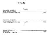
mobile station 104 and thebase stations Fig. 12 is a timing chart showing radio wave propagation in the conventional radio communication system. For example, themobile station 104 receives the transmitted signals from the twobase stations Fig. 12 , in a specified area (in the case where distances between themobile station 104 and the two base stations are approximately equal), the power of the signal RA received from thebase station 107A is equal to the power of the signal RB received from thebase station 107B, but their polarities become occasionally opposite to each other. In this case, the two received signals RA and RB offsets each other, and when they are synthesized, no signal exists. - Another example of the conventional radio communication system is a radio communication system disclosed in Patent Gazette No.
2572765 Fig. 13 is a diagram showing a structure of such a radio communication system where a plurality of antennas are provided to the base station and which point is different fromFig. 11 . InFig. 13 ,legend 107 represents a base station,legend 101 represents a transmission information input terminal where transmission information is input from a network, andlegend 102 represents a modulator. Further, legend 103A represents a first antenna of thebase station 107,legend 106 represents a delay unit,legend 103C represents a second antenna of thebase station 107,legend 104 represents a mobile station andlegend 105 represents an antenna of themobile station 104. - In the radio communication system having the above structure, the
base station 107 transmits information via thefirst antenna 103A, and thedelay unit 106 delays the same information by not less than 1 symbol. Thereafter, thebase station 107 transmits the information via thesecond antenna 103C. Themobile station 104 receives signals transmitted from the twoantennas base station 107 via theantenna 105. At this time, since the signals from the two antennas on the transmission side have time difference of not less than 1 symbol, the time difference is corrected by an equalizer in themobile station 104. - Further, in the radio communication system shown in
Fig. 13 , if the radio wave environments in thetransmission antennas - That is, as shown in
Fig. 11 , when the radio communication system which covers a wide area is realized, there arises a problem that the signals from a plurality of base stations offset each other and reception of the signals is difficult in a specified position. On the other hand, as shown inFig. 13 , when the base station outputs a normal transmission signal and a transmission signal delayed from the normal transmission signal, there arises a problem that the structure of the equalizer on the receiving side becomes complicated. -
EP 0 767 546 discloses a method and an apparatus for introducing very small varying phase offsets to the signals transmitted from a plurality of antennas so these signals would destructively interfere only for a small fraction of time. The disclosure refers to using multiple base stations comprising a plurality of antennas, whereby a plurality of symbol copies is made out of a digital signal, the Gray coded 4-PSK complex symbols are multiplied by the output of a unit delay register (37) and the resulting symbol is multiplied by a complex time-varying function (amplitude weight and phase offset). -
EP 0 755 127 discloses a CDMA diversity transmitter comprising a plurality of antennas and signal transmission units for transmitting k user signals weighted by different values from the respective antennas. Additionally, the transmitter comprises delay units, one per antenna, that set different transmission timings of signals from the different antennas. -
US-A-5423059 discloses a simulcast communication system, wherein a controller determines enhanced coverage area delays for each of different transmitters in order to enhance the transmitted signal quality. - The present invention is devised in order to solve the above problems. It is an object of the invention to provide a radio communication system and a transmitter which previously prevent the phenomenon that all signals decay after synthesization in mobile stations between a plurality of base stations and are capable of covering a wide area with a simple structure.
- These problems are solved by the communication system according to claim 1 and the transmitter according to
claim 3. - A radio communication system according to one aspect is constituted so as to have a plurality of antennas each transmitting same signal and a receiver that receives these signals, and is characterized in that signals which are supplied to the plurality of antennas are signals which are obtained by differently delaying modulated signals and by carrying out weighting synthesization on them, and at least one of delay amount and weighting factor is set to different values in each of the antennas.
- According to the above invention, at least one of the delay amount and weighting factor in the signal filtering sections corresponding to the plural antennas in one transmitter is set to a different value between the adjacent antennas so that the conventionally occurring phenomenon that the filtered signals decays in a specified area is previously prevented. Moreover, even if the transmitters have only one antenna, the same effect as that of the structure having a plurality of antennas can be produced. Further, the delay can be set so as not to be not less than 1 symbol so that the circuit size of the equalizer in the receiver is reduced.
- A radio communication system according to another aspect is characterized in that an equalizer in the receiver demodulates signals transmitted from the plurality of antennas.
- According to the above invention, the receiver demodulates the filtered signals from the plural antennas using the equalizer.
- A transmitter according to another aspect is characterized in that in the case where same signals are transmitted from a plurality of antennas, signals which are supplied to respective antennas are signals which are obtained by differently delaying modulated signals and by carrying out weighting synthesization on them, and at least one of delay amount and weighting factor is set to different values in the antennas.
- According to the above invention, at least one of the delay amount and weighting factor in respective signal filtering sections corresponding to the plural antennas of one transmitter is set to a different value between the adjacent antennas so that the conventionally occurring phenomenon that the fil tered signals erupt in a specified area is previously prevented.
- A transmitter according to another aspect is characterized in that in the case where same signals are transmitted from a plurality of antennas, signals which are supplied to respective antennas are signals which are obtained by delaying original modulated signals, by weighting the delayed signals and by synthesizing the weighted signals with the original modulated signals, and at least one of delay amount and weighting factor is set to different values for each of said antennas.
- According to the above invention, at least one of the delay amount and weighting factor in respective signal filtering sections corresponding to the plural antennas of one transmitter is set to a different value between the adjacent antennas so that the conventionally occurring phenomenon that the filtered signals erupt in a specified area is previously prevented.
-
Fig. 1 is a diagram showing a structure of a radio communication system according to a first embodiment of the present invention;Fig. 2 is a timing chart showing radio wave propagation in the radio communication system according to the first embodiment,Fig. 3 is a timing chart showing radio wave propagation in the radio communication system which is operated by a condition different from one shown inFig. 2 ;Fig. 4 is a diagram showing a concrete example in the case where the radio communication system of the present invention is applied to communication between a base station and a mobile station;Fig. 5 is a diagram showing a structure of the radio communication system according to a second embodiment;Fig. 6 is a diagram showing a structure ofsignal filtering sections Fig. 7 is a timing chart showing the radio wave propagation in the radio communication system according to the second embodiment;Fig. 8 is a diagram showing a concrete example in the case where the radio communication system is applied to communication between the base station and the mobile station;Fig. 9 is a diagram showing a structure of the radio communication system according to a third embodiment of the present invention;Fig. 10 is a diagram showing a concrete example in the case where the radio communication system of the present invention is applied to communication between the base station and the mobile station;Fig. 11 is a diagram showing a structure of a conventional radio communication system;Fig. 12 is a timing chart showing radio wave propagation in the conventional radio communication system; andFig. 13 is a diagram showing a structure of a radio communication system different from the one shown inFig. 11 . - In order to further detail the present invention, there will be explained below embodiments of the present invention with reference to the attached drawings.
- First of all, the structure of the radio communication system of the present invention will be explained.
Fig. 1 shows the structure of the radio communication system according to a first embodiment of the present invention. InFig. 1 , legend 1 represents a transmission information input terminal,legends legend 3 represents a receiver, andlegends legends legends legends legends legends legend 10 an antenna of thereceiver 3. - The radio communication system having the above structure is constituted so that at least one antenna (two antennas have been shown in the figure for convenience of explanation) is provided in each of the
transmitters antennas delay units - In the present embodiment, two transmitters have been shown for the convenience of explanation, but the present invention is not limited to this. That is, three or more transmitters may be provided. Similarly, two antennas have been shown in each of the transmitters, but the present invention is not limited to this. That is, any number of antennas may be used.
- The structure shown in the base station of
Fig. 1 is the one that are required to fulfill all the important functions. For example, this function includes a case where an up-converting process for converting a base band signal into RF frequency has been performed at the time of outputting from themodulators modulators delay units - In the present embodiment, arbitrary delay is given to the respective antennas, and at least one delay output between the transmitters is set so as to have a different output power. For this reason, all the signals do not decay after synthesization. Moreover, the respective transmitters set their radio wave environments independently so that the characteristic can be improved by the diversity effect. Further, the delay cannot be optionally set to not less than 1 symbol, and a circuit size of an equalizer (not shown) can be reduced greatly as compared to the conventional one.
- Operation of the radio communication system having the above structure will be explained here. For example, in the
transmitter 2A, after an output level of the signal to be transmitted is regulated by thefirst gain adjuster 5A, the signal is transmitted from thefirst antenna 8A without delay. On the other hand, the signal is delayed by thedelay unit 6A. The output level of this signal is further regulated by thesecond gain adjuster 7A so as to be transmitted from thesecond antenna 9A. Similarly, in thetransmitter 2B, after an output level of the signal to be transmitted is regulated by thefirst gain adjuster 5B, the signal is transmitted from thefirst antenna 8B without delay. On the other hand, the signal is delayed by thedelay unit 6B. The output level of this signal is regulated by thesecond gain adjuster 7B so as to be transmitted from thesecond antenna 9B. Thereceiver 3 receives the signals transmitted from the fourantennas antenna 10 and executes the demodulation process. -
Fig. 2 is a timing chart showing radio wave propagation of the radio communication system according to the present embodiment. In the present embodiment, the delay values of thedelay units first gain adjuster 5A (transmitter 2A) and thesecond gain adjuster 7B (transmitter 2B) are equal, and the gains of thesecond gain adjuster 7A (transmitter 2A) and thefirst gain adjuster 5B (transmitter 2B) are equal. However, the gains of the first gain adjuster and the second gain adjuster in the respective transmitters are not same. Namely, as for the delay outputs between the adjacent transmitters (the combinations of thefirst antennas second antennas - Normally, the distance between the
first antenna 8A and thesecond antenna 9A in thetransmitters 2A is negligibly small as compared to the distance between two transmitters. Similarly, the distance between thefirst antenna 8B and thesecond antenna 9B in thetransmitter 2B is negligibly small as compared to the distance between the transmitters. Therefore, in this structure, a condition that a signal receiving environment becomes the most strict is the case where thereceiver 3 is positioned at almost half way between two transmitters. Further, in thereceiver 3, the received signal level becomes the lowest when the delay values of thedelay units Fig. 2 , and when a signal component RA from thefirst antenna 8A in thetransmitter 2A and a signal component RB from thefirst antenna 8B in thetransmitter 2B have opposite phases, and a signal component RC from thesecond antenna 9A in thetransmitter 2A and a signal component RD from thesecond antenna 9B in thetransmitter 2B have opposite phases. - In the radio communication system of the present embodiment, gains of the
first gain adjuster 5A and thefirst gain adjuster 5B are different from the gains of thesecond gain adjuster 7A and thesecond gain adjuster 7B. For this reason, in the above explained cases, even if the received signals with the same delay amount are input with opposite phases, the received signals never offset each other completely and therefore remain. Precisely, inFig. 2 , two signals of a signal component CA and a signal component CC as filtered signals whose delay amounts are different remain. - Meanwhile, if the signal component RC from the
second antenna 9A in thetransmitter 2A and the signal component RD from thesecond antenna 9B in thetransmitter 2B have different phases and the signal levels are equal, the radio communication system according to the present embodiment operates as follows. This condition can be satisfied under the environment that thereceiver 3 exists near thetransmitter 2A.Fig. 3 is a timing chart showing radio wave propagation in the radio communication system in the above case. - In this case, as for the signal component RA from the
first antenna 8A and the signal component RB from thefirst antenna 8B, the level of the signal component RA becomes always high. For this reason, in thereceiver 3, for example, the signal component RC from thesecond antenna 9A offsets the signal component RD from thesecond antenna 9B, but the signal component RA does not offset the signal component RB. For this reason, the signal components always remain. - In the present embodiment, the combinations of the transmission powers in the delay outputs (including no delay) from a plurality of antennas of the respective transmitters are different from each other between the adjacent transmitters. As a result, since the signal components do not offset each other, the conventionally-occurring phenomenon that the signal after the synthesization decays in a specified area can be previously prevented. Moreover, the radio wave environment of the antennas is set independently so that the characteristic can be improved by the diversity effect. Further, since the delay can be set so as not to be more than 1 symbol, the circuit size of the equalizer in the receiver can be reduced greatly as compared to the conventional one.
-
Fig. 4 is a diagram showing a concrete example in the case where the transmitters in the communication system shown inFig. 1 are replaced by base stations (corresponding tobase stations 31A and 32B in the diagram), and the receiver is replaced by mobile station (corresponding to mobile station 32), and the radio communication system of the present invention is applied to the communication between the base stations and the mobile station. Two base stations have been shown inFig. 4 for convenience of the explanation, but the present invention is not limited to this. That is, three or more base stations may be used. Moreover, two antennas are shown in each of the base stations, but the present invention is not limited to this. That is, any number of antennas may be used. -
Fig.5 shows a structure of the radio communication system according to a second embodiment. This embodiment is not an embodiment of the invention but helpful to understand certain aspects of the invention. The same legends are provided to the parts of the structure which are the same as those of the first embodiment, and the explanation thereof is omitted. InFig. 5 , 2C and 2D are transmitters, and 11A and 11B are signal filtering sections. - Further,
Fig. 6 is a diagram showing a structure of thesignal filtering sections Fig. 6 ,legend 21 represents a modulated signal input terminal,legend 22 represents a delay unit,legend 23 represents a complex weight section,legend 24 represents a synthesization circuit, andlegend 25 represents a filtered signal output terminal. - The radio communication system having the above structure is constituted so that at least one antenna (only one antenna is shown for convenience of explanation) is provided in a plurality of transmitters (only two transmitters are shown for convenience of explanation) 2C and 2D. Modulated signals which are output from the
antennas synthesization circuit 24 by using the original modulated signals and the arbitrarily delayed modulated signals so that filtered signals are generated. Thereafter, the transmitters output transmission signals from the antennas with set output power. - In the present embodiment, two transmitters are shown for convenience of explanation, but three or more transmitters may be used. Moreover, one antenna is shown in each of the transmitters, but the present invention is not limited to this. That is, any number of antennas may be used.
- The structure shown in
Fig. 5 is only the one that is required to fulfill all the important functions. For example, this function includes a case where an up-converting process for converting a base band signal into RF frequency has been performed at the time of outputting from themodulators - Operation of the radio communication system having the above structure will be explained here. For example, in the
transmitter 2C, after thesignal filtering section 11A executes the weight synthesization on the signal modulated by themodulator 4A so as to generate the filtered signal, the filtered signal is transmitted from theantenna 12A. Similarly, in thetransmitter 2D, after thesignal filtering section 11B executes the weight synthesization on the signal modulated by themodulator 4B so as to generate the filtered signal, the filtered signal is transmitted from theantenna 12B. Thereceiver 3 receives the signals transmitted from the twoantennas antenna 10, and executes the demodulation process. -
Fig. 7 is a timing chart showing the radio wave propagation in the radio communication system according to the present embodiment. The present embodiment will explain the case where after thesynthesization sections complex weight section 23, and the weighted signals which undergo the complex weighting are synthesized with the original modulated signals by thesynthesization circuit 24. Here, the delay of thedelay unit 22 in thesignal filtering section 11A is set to 1 symbol, and a value of phase rotation/amplitude regulation in the complex weight section 23 (hereinafter, referred to as a weighting factor) is set to -1 (180° phase rotation) . Further, the delay of thedelay unit 22 in thesignal filtering section 11B is set to 1 symbol, and a weighting factor of thecomplex weight section 23 is set to 1 (without phase rotation) . The setting the delay amount and weight factors in the respective signal filtering sections is not limited to the above setting, and at least one of them may be different between the transmitters. - In the above structure, the condition that the signal receiving environment becomes the most strict is the case where the
receiver 3 is positioned in between the two transmitters. In the first embodiment, since the undelayed signal and the delayed signal are transmitted from different antennas, the phase relationship between these signals can attain any arbitrary value. However, in the present embodiment, since the filtered signals are transmitted from one antenna, the phase relationship between these signals is determined constantly by thecomplex weight section 23. - In this case, in the radio communication system according to the present embodiment, the signal component RC which is delayed in the
transmitter 2C has a phase opposite to that of the signal component RA which is not delayed in thetransmitter 2C, and the signal component RD which is delayed in thetransmitter 2D always has the phase which is the same as that of the signal component RB which is not delayed in thetransmitter 2D. For this reason, when the signal component RA and the signal component RB have opposite phases, the signal component RC and the signal component RD always have the same phases. As a result, the received signals do not offset each other completely so as to always remain. Precisely, inFig. 7 , the two signals of the signal component CA and the signal component CC are synthesized in the receiver. - In the present embodiment, at least one of the delay amount and weighting factors is set to a different value for adjacent transmitters so that the signal components do not offset each other. For this reason, the conventionally occurring phenomenon that the filtered signal decays in a specified area can be previously prevented. Moreover, in the present embodiment, even if the transmitters have respectively one antenna, the effect which is the same as that in the structure of the first embodiment having many antennas can be produced. Further, since the delay can be set to not more than 1 symbol, the circuit size of the equalizer in the receiver can be reduced greatly as compared to the conventional one.
-
Fig. 8 is a diagram showing a concrete example in the case where the transmitters in the communication system shown inFig. 5 are replaced by base stations (corresponding tobase stations 31C and 32D in the drawing), and the receiver is replaced by a mobile station (corresponding to a mobile station 32), and the radio communication system is applied to the communication between the base stations and the mobile station. Two base stations have been shown inFig. 8 for convenience of explanation but three or more base stations may be used. Moreover, one antenna is shown in each of the base stations, but any number of antennas may be used. -
Fig.9 shows a structure of the radio communication system according to a third embodiment of the present invention. The same legends are provided to parts of the structure which are the same as those in the first and second embodiments, and the explanation thereof is omitted. InFig. 9 ,legend 2E represents a transmitter, legend 11C represents a first signal filtering section, andlegend 11D represents a second signal filtering section. The signal filtering sections in the present embodiment are the same as that shown inFig. 6 according to the second embodiment. - The structure shown in
Fig. 9 is only the ideal structure which fulfills all the important functions. For example, this function includes a case where an up-converting process for converting a base band signal into RF frequency has been performed at the time of outputting from themodulators - A difference between the present embodiment and the second embodiment is that one antenna is provided to each of the two transmitters but the two signal filtering sections are provided to one transmitter so that the total number of the antennas is two. Therefore, in the present embodiment, at least one of the delay amount and weighting factors in the signal filtering sections corresponding to a plurality of antennas provided to one transmitter is set to different values for the adjacent antennas. As a result, the same effect as that of the second embodiment can be produced.
-
Fig. 10 is a diagram showing a concrete example in the case where the transmitter in the communication system shown inFig. 9 is replaced by a base station (corresponding to abase station 32A in the drawing), and the receiver is replaced by a mobile station (corresponding to a mobile station 31), and the radio communication system of the present invention is applied to the communication between the base station and the mobile station. However, inFig. 9 andFig. 10 , two antennas are provided to each of the base stations, but the present invention is not limited to this. That is, any number of antennas may be used. - The radio communication system of the present invention is useful for radio communication systems including a mobile phone. Particularly, this system is suitable to a radio communication system which should cover a wide area in an environment that reception of a signal is difficult such as a place where signals from a plurality of base stations offset each other.
Claims (3)
- A radio communication system in which a transmitter (2E) having a plurality of antennas (12A, 12B) transmits same signals and a receiver (3) receives these signals, characterized in that signals which are supplied to said plurality of antennas (12A, 12B) are signals which are obtained by delaying original modulated signals, by weighting the delayed signals and by synthesizing the weighted signals with the original modulated signals, and at least one of delay amount and weighting factor is set to different values for each of said antennas (12A, 12B).
- The radio communication system according to claim 1, characterized in that an equalizer in said receiver (3) demodulates signals transmitted from said plurality of antennas.
- A transmitter having a plurality of antennas (12A, 12B) characterized in that in the case where same signals are transmitted from a plurality of antennas (12A, 12B), signals which are supplied to said antennas (12A, 12B) are signals which are obtained by delaying original modulated signals, by weighting the delayed signals and by synthesizing the weighted signals with the original modulated signals, and at least one of delay amount and weighting factor is set to different values for each of said antennas.
Applications Claiming Priority (3)
| Application Number | Priority Date | Filing Date | Title |
|---|---|---|---|
| JP3665599 | 1999-02-16 | ||
| JP3665599 | 1999-02-16 | ||
| PCT/JP1999/005646 WO2000049730A1 (en) | 1999-02-16 | 1999-10-13 | Radio communication system, transmitter and receiver |
Publications (3)
| Publication Number | Publication Date |
|---|---|
| EP1073214A1 EP1073214A1 (en) | 2001-01-31 |
| EP1073214A4 EP1073214A4 (en) | 2005-02-02 |
| EP1073214B1 true EP1073214B1 (en) | 2008-12-17 |
Family
ID=12475883
Family Applications (1)
| Application Number | Title | Priority Date | Filing Date |
|---|---|---|---|
| EP99947875A Expired - Lifetime EP1073214B1 (en) | 1999-02-16 | 1999-10-13 | Radio communication system, transmitter and receiver |
Country Status (5)
| Country | Link |
|---|---|
| US (3) | US7346316B1 (en) |
| EP (1) | EP1073214B1 (en) |
| DE (1) | DE69940111D1 (en) |
| TW (1) | TW441203B (en) |
| WO (1) | WO2000049730A1 (en) |
Cited By (3)
| Publication number | Priority date | Publication date | Assignee | Title |
|---|---|---|---|---|
| US7978649B2 (en) | 2004-07-15 | 2011-07-12 | Qualcomm, Incorporated | Unified MIMO transmission and reception |
| US7991065B2 (en) | 2004-06-30 | 2011-08-02 | Qualcomm, Incorporated | Efficient computation of spatial filter matrices for steering transmit diversity in a MIMO communication system |
| US8909174B2 (en) | 2004-05-07 | 2014-12-09 | Qualcomm Incorporated | Continuous beamforming for a MIMO-OFDM system |
Families Citing this family (37)
| Publication number | Priority date | Publication date | Assignee | Title |
|---|---|---|---|---|
| GB2364205B (en) * | 2000-06-29 | 2002-09-18 | Piping Hot Networks Ltd | Broadband communications |
| AU2002224891A1 (en) * | 2000-11-27 | 2002-06-03 | Telefonaktiebolaget Lm Ericsson (Publ) | Method and apparatus for improving channel estimates using space-time coding |
| US8204149B2 (en) | 2003-12-17 | 2012-06-19 | Qualcomm Incorporated | Spatial spreading in a multi-antenna communication system |
| US7336746B2 (en) | 2004-12-09 | 2008-02-26 | Qualcomm Incorporated | Data transmission with spatial spreading in a MIMO communication system |
| US8169889B2 (en) | 2004-02-18 | 2012-05-01 | Qualcomm Incorporated | Transmit diversity and spatial spreading for an OFDM-based multi-antenna communication system |
| US8285226B2 (en) | 2004-05-07 | 2012-10-09 | Qualcomm Incorporated | Steering diversity for an OFDM-based multi-antenna communication system |
| CN1989722B (en) * | 2004-05-17 | 2011-05-18 | 高通股份有限公司 | Time varying cyclic delay diversity of OFDM |
| US8233555B2 (en) | 2004-05-17 | 2012-07-31 | Qualcomm Incorporated | Time varying delay diversity of OFDM |
| US7978778B2 (en) | 2004-09-03 | 2011-07-12 | Qualcomm, Incorporated | Receiver structures for spatial spreading with space-time or space-frequency transmit diversity |
| DE112006000618T5 (en) | 2005-03-15 | 2008-02-07 | Trapeze Networks, Inc., Pleasanton | System and method for distributing keys in a wireless network |
| US8059608B2 (en) * | 2005-06-14 | 2011-11-15 | Qualcomm Incorporated | Transmit spatial diversity for cellular single frequency networks |
| WO2007044986A2 (en) | 2005-10-13 | 2007-04-19 | Trapeze Networks, Inc. | System and method for remote monitoring in a wireless network |
| US8638762B2 (en) | 2005-10-13 | 2014-01-28 | Trapeze Networks, Inc. | System and method for network integrity |
| US7573859B2 (en) | 2005-10-13 | 2009-08-11 | Trapeze Networks, Inc. | System and method for remote monitoring in a wireless network |
| US7724703B2 (en) | 2005-10-13 | 2010-05-25 | Belden, Inc. | System and method for wireless network monitoring |
| JP4451400B2 (en) * | 2006-01-18 | 2010-04-14 | 株式会社エヌ・ティ・ティ・ドコモ | Transmitting apparatus and transmitting method |
| EP1990930A1 (en) | 2006-03-17 | 2008-11-12 | Matsushita Electric Industrial Co., Ltd. | Wireless transmission system and wireless transmitting method, and wireless station and transmitting station used in the same |
| US8543070B2 (en) | 2006-04-24 | 2013-09-24 | Qualcomm Incorporated | Reduced complexity beam-steered MIMO OFDM system |
| US7558266B2 (en) | 2006-05-03 | 2009-07-07 | Trapeze Networks, Inc. | System and method for restricting network access using forwarding databases |
| US8966018B2 (en) | 2006-05-19 | 2015-02-24 | Trapeze Networks, Inc. | Automated network device configuration and network deployment |
| US8290089B2 (en) | 2006-05-22 | 2012-10-16 | Qualcomm Incorporated | Derivation and feedback of transmit steering matrix |
| US9191799B2 (en) | 2006-06-09 | 2015-11-17 | Juniper Networks, Inc. | Sharing data between wireless switches system and method |
| US9258702B2 (en) | 2006-06-09 | 2016-02-09 | Trapeze Networks, Inc. | AP-local dynamic switching |
| US8818322B2 (en) | 2006-06-09 | 2014-08-26 | Trapeze Networks, Inc. | Untethered access point mesh system and method |
| US8340110B2 (en) | 2006-09-15 | 2012-12-25 | Trapeze Networks, Inc. | Quality of service provisioning for wireless networks |
| US7873061B2 (en) | 2006-12-28 | 2011-01-18 | Trapeze Networks, Inc. | System and method for aggregation and queuing in a wireless network |
| US8902904B2 (en) | 2007-09-07 | 2014-12-02 | Trapeze Networks, Inc. | Network assignment based on priority |
| US8238942B2 (en) | 2007-11-21 | 2012-08-07 | Trapeze Networks, Inc. | Wireless station location detection |
| US8150357B2 (en) * | 2008-03-28 | 2012-04-03 | Trapeze Networks, Inc. | Smoothing filter for irregular update intervals |
| US8978105B2 (en) | 2008-07-25 | 2015-03-10 | Trapeze Networks, Inc. | Affirming network relationships and resource access via related networks |
| US8238298B2 (en) | 2008-08-29 | 2012-08-07 | Trapeze Networks, Inc. | Picking an optimal channel for an access point in a wireless network |
| FR2937483A1 (en) * | 2008-10-17 | 2010-04-23 | Thomson Licensing | METHOD FOR RECEIVING A SIGNAL AND TRANSMITTING METHOD THEREOF |
| EP2854318B1 (en) | 2012-05-22 | 2020-11-04 | Sun Patent Trust | Transmission method and transmission system |
| WO2014097766A1 (en) * | 2012-12-21 | 2014-06-26 | 京セラ株式会社 | Mobile communication system, communication control method, base station, and user terminal |
| US9647861B1 (en) * | 2014-01-30 | 2017-05-09 | Rockwell Collins, Inc. | Multiple antenna transmission of pulsed data communication messages with phase or time dithering for reduction of static interference nulls |
| DE102015122420A1 (en) * | 2015-12-21 | 2017-06-22 | Fraunhofer-Gesellschaft zur Förderung der angewandten Forschung e.V. | A transmission arrangement for generating a signal pattern suitable for a location and receiving arrangement for performing a localization |
| WO2020183671A1 (en) * | 2019-03-13 | 2020-09-17 | 三菱電機株式会社 | Transmission device and base station |
Family Cites Families (42)
| Publication number | Priority date | Publication date | Assignee | Title |
|---|---|---|---|---|
| DE3020176A1 (en) * | 1980-05-28 | 1981-12-03 | Licentia Patent-Verwaltungs-Gmbh, 6000 Frankfurt | METHOD AND ARRANGEMENT FOR SIMULTANEOUSLY SENDING MESSAGES ON SEVERAL SAME-WAVE TRANSMITTERS |
| JPS5815341A (en) * | 1981-07-22 | 1983-01-28 | Nec Corp | Transmission diversity system |
| JP2572765B2 (en) * | 1987-05-19 | 1997-01-16 | 日本電信電話株式会社 | Transmission path diversity transmission method |
| US4896371A (en) * | 1987-11-20 | 1990-01-23 | Kahn Leonard R | Synchronous AM transmission system having reduced self interference effects |
| JPH01198834A (en) * | 1988-02-03 | 1989-08-10 | Fujitsu Ltd | Line switching device |
| US5101501A (en) | 1989-11-07 | 1992-03-31 | Qualcomm Incorporated | Method and system for providing a soft handoff in communications in a cdma cellular telephone system |
| JP2795935B2 (en) | 1989-11-24 | 1998-09-10 | 三菱電機株式会社 | Maximum likelihood sequence estimator |
| JPH03195129A (en) | 1989-12-22 | 1991-08-26 | Mitsubishi Electric Corp | Maximum likelihood series estimating device |
| US5060302A (en) * | 1990-02-28 | 1991-10-22 | At&T Bell Laboratories | Automatic adjustment of optical power output of a plurality of optical transmitters |
| CA2037824C (en) | 1990-03-20 | 1999-11-09 | Hiroshi Kubo | Diversity circuit and frame phase (or sampling timing) estimation circuit using the diversity circuit |
| US5103459B1 (en) | 1990-06-25 | 1999-07-06 | Qualcomm Inc | System and method for generating signal waveforms in a cdma cellular telephone system |
| JPH04144428A (en) | 1990-10-05 | 1992-05-18 | Nippon Telegr & Teleph Corp <Ntt> | Mobile radio communication system |
| US5513176A (en) | 1990-12-07 | 1996-04-30 | Qualcomm Incorporated | Dual distributed antenna system |
| JP2510903B2 (en) | 1991-06-03 | 1996-06-26 | 東海ゴム工業株式会社 | Fluid-filled mount device and manufacturing method thereof |
| US5214675A (en) * | 1991-07-02 | 1993-05-25 | Motorola, Inc. | System and method for calculating channel gain and noise variance of a communication channel |
| GB2259430B (en) | 1991-09-07 | 1996-05-01 | Motorola Ltd | Radio receiver and transmitter providing diversity |
| US5479448A (en) * | 1992-03-31 | 1995-12-26 | At&T Corp. | Method and apparatus for providing antenna diversity |
| JP3122267B2 (en) * | 1992-12-24 | 2001-01-09 | 株式会社日立国際電気 | Diversity communication system |
| US5812935A (en) * | 1993-04-17 | 1998-09-22 | Hughes Electronics | Cellular system employing base station transmit diversity according to transmission quality level |
| SG66285A1 (en) * | 1993-04-29 | 1999-07-20 | Ericsson Inc | Use of diversity transmission to relax adjacent channel requirements in mobile telephone systems |
| US5423059A (en) * | 1993-07-29 | 1995-06-06 | Motorola Inc. | Method for enhancing signal quality in a simulcast communication system |
| CA2118355C (en) * | 1993-11-30 | 2002-12-10 | Michael James Gans | Orthogonal polarization and time varying offsetting of signals for digital data transmission or reception |
| WO1996008088A1 (en) | 1994-09-09 | 1996-03-14 | Motorola Inc. | Diversity receiver with combiner for equalization and diversity transmitter with splitter and delay |
| US5748683A (en) * | 1994-12-29 | 1998-05-05 | Motorola, Inc. | Multi-channel transceiver having an adaptive antenna array and method |
| JPH08195703A (en) * | 1995-01-17 | 1996-07-30 | Toshiba Corp | Radio communication equipment |
| JP2705623B2 (en) * | 1995-03-22 | 1998-01-28 | 日本電気株式会社 | Diversity transmission / reception method and transceiver |
| RU2153226C2 (en) * | 1995-06-06 | 2000-07-20 | Глоубалстар Л.П. | Device for controlling distributed signal transmission system using satellite retransmitters |
| DE69637911D1 (en) | 1995-07-19 | 2009-06-04 | Nec Corp | Code diversity diversity diversity transmission system |
| US5848103A (en) * | 1995-10-04 | 1998-12-08 | Lucent Technologies Inc. | Method and apparatus for providing time diversity |
| JPH09116475A (en) * | 1995-10-23 | 1997-05-02 | Nec Corp | Time diversity transmission/reception system |
| JPH09197059A (en) | 1996-01-23 | 1997-07-31 | Shingo Seki | Magnetic sensor |
| US6049720A (en) * | 1996-04-12 | 2000-04-11 | Transcrypt International / E.F. Johnson Company | Link delay calculation and compensation system |
| US6034987A (en) * | 1996-12-17 | 2000-03-07 | Ericsson Inc. | System for improving the quality of a received radio signal |
| JP3563219B2 (en) * | 1996-12-20 | 2004-09-08 | 富士通株式会社 | Mobile communication system and its radio base station and exchange |
| US5884149A (en) * | 1997-02-13 | 1999-03-16 | Nokia Mobile Phones Limited | Mobile station having dual band RF detector and gain control |
| JP3914268B2 (en) | 1997-05-08 | 2007-05-16 | 株式会社日立製作所 | Train radio communication system and radio transceiver thereof |
| US6141542A (en) * | 1997-07-31 | 2000-10-31 | Motorola, Inc. | Method and apparatus for controlling transmit diversity in a communication system |
| JP3180733B2 (en) | 1997-10-17 | 2001-06-25 | 三菱電機株式会社 | Wireless communication system |
| US6377812B1 (en) * | 1997-11-20 | 2002-04-23 | University Of Maryland | Combined power control and space-time diversity in mobile cellular communications |
| US6477377B2 (en) * | 1998-05-29 | 2002-11-05 | Ericsson Inc. | Cellular radiotelephone systems and methods that broadcast a common control channel over multiple radio frequencies |
| US6259730B1 (en) * | 1998-11-10 | 2001-07-10 | Lucent Technologies, Inc. | Transmit diversity and reception equalization for radio links |
| US6587515B1 (en) * | 1999-02-10 | 2003-07-01 | Hamid Jafarkhani | Differential transmitter diversity technique for wireless communications |
-
1999
- 1999-10-13 EP EP99947875A patent/EP1073214B1/en not_active Expired - Lifetime
- 1999-10-13 DE DE69940111T patent/DE69940111D1/en not_active Expired - Lifetime
- 1999-10-13 WO PCT/JP1999/005646 patent/WO2000049730A1/en active Application Filing
- 1999-10-16 TW TW088117913A patent/TW441203B/en not_active IP Right Cessation
-
2000
- 2000-10-06 US US09/685,333 patent/US7346316B1/en not_active Expired - Fee Related
-
2007
- 2007-10-31 US US11/931,587 patent/US8027649B2/en not_active Expired - Fee Related
- 2007-10-31 US US11/931,990 patent/US7929922B2/en not_active Expired - Fee Related
Cited By (4)
| Publication number | Priority date | Publication date | Assignee | Title |
|---|---|---|---|---|
| US8909174B2 (en) | 2004-05-07 | 2014-12-09 | Qualcomm Incorporated | Continuous beamforming for a MIMO-OFDM system |
| US8923785B2 (en) | 2004-05-07 | 2014-12-30 | Qualcomm Incorporated | Continuous beamforming for a MIMO-OFDM system |
| US7991065B2 (en) | 2004-06-30 | 2011-08-02 | Qualcomm, Incorporated | Efficient computation of spatial filter matrices for steering transmit diversity in a MIMO communication system |
| US7978649B2 (en) | 2004-07-15 | 2011-07-12 | Qualcomm, Incorporated | Unified MIMO transmission and reception |
Also Published As
| Publication number | Publication date |
|---|---|
| EP1073214A1 (en) | 2001-01-31 |
| EP1073214A4 (en) | 2005-02-02 |
| US20080064428A1 (en) | 2008-03-13 |
| WO2000049730A1 (en) | 2000-08-24 |
| US7346316B1 (en) | 2008-03-18 |
| US20080064335A1 (en) | 2008-03-13 |
| US7929922B2 (en) | 2011-04-19 |
| TW441203B (en) | 2001-06-16 |
| DE69940111D1 (en) | 2009-01-29 |
| US8027649B2 (en) | 2011-09-27 |
Similar Documents
| Publication | Publication Date | Title |
|---|---|---|
| EP1073214B1 (en) | Radio communication system, transmitter and receiver | |
| CN101807949B (en) | Communication device, communication control method and communication system | |
| CN100490349C (en) | Frequency related calibration of a wideband radio system using narrowband channels | |
| US6249250B1 (en) | Adaptive variable directional antenna | |
| KR100199316B1 (en) | Multi channel digital transceiver and method thereof | |
| US7395042B2 (en) | Enhancing signals in a two-way radio system | |
| EP1220506A1 (en) | Beam formation circuit and an apparatus and a method of receiving radio frequency signals making use of a smart antenna | |
| EP0883207A2 (en) | Adaptive array antenna receiving apparatus | |
| JPH06169273A (en) | Radio receiver, transmitter and repeater for execution of diversity | |
| KR19990077650A (en) | Multimode radio transmission system | |
| US7013166B2 (en) | Multi-carrier receiver architecture | |
| US20090088103A1 (en) | Point-to-multipoint communication terminal having a single RF chain | |
| EP0800737B1 (en) | Multiple access digital transmitter and receiver | |
| US7599401B2 (en) | Transmission device and transmission method | |
| EP0479744B1 (en) | A method for reducing the risk of poor reception in a mobile telephony system | |
| JP3589605B2 (en) | Adaptive array antenna transceiver | |
| WO1995012927A1 (en) | A method for transmitting radio signals, and a tdma transceiver | |
| US6704345B1 (en) | Transmission/reception apparatus and transmission/reception method | |
| JP3276360B2 (en) | Wireless communication system and transmitter | |
| WO1997025784A1 (en) | Ofdm system and ofdm apparatus | |
| US20040166903A1 (en) | Base station | |
| EP1792460A1 (en) | Relay for multi-carrier wireless communications system | |
| US20080012754A1 (en) | Delay based sector beam synthesis in a multi-beam antenna system | |
| EP1188252B1 (en) | Method and arrangement for radio communication with an electrically controlled antenna | |
| JPH0746799B2 (en) | Digital signal transmission method |
Legal Events
| Date | Code | Title | Description |
|---|---|---|---|
| PUAI | Public reference made under article 153(3) epc to a published international application that has entered the european phase |
Free format text: ORIGINAL CODE: 0009012 |
|
| 17P | Request for examination filed |
Effective date: 20000913 |
|
| AK | Designated contracting states |
Kind code of ref document: A1 Designated state(s): AT BE CH CY DE DK ES FI FR GB GR IE IT LI LU MC NL PT SE |
|
| RBV | Designated contracting states (corrected) |
Designated state(s): DE FR GB |
|
| A4 | Supplementary search report drawn up and despatched |
Effective date: 20041217 |
|
| 17Q | First examination report despatched |
Effective date: 20050304 |
|
| RAP1 | Party data changed (applicant data changed or rights of an application transferred) |
Owner name: MITSUBISHI DENKI KABUSHIKI KAISHA |
|
| GRAP | Despatch of communication of intention to grant a patent |
Free format text: ORIGINAL CODE: EPIDOSNIGR1 |
|
| GRAS | Grant fee paid |
Free format text: ORIGINAL CODE: EPIDOSNIGR3 |
|
| RIN1 | Information on inventor provided before grant (corrected) |
Inventor name: KUBO, HIROSHIMITSUBISHI DENKI KABUSHIKI KAISHA |
|
| GRAA | (expected) grant |
Free format text: ORIGINAL CODE: 0009210 |
|
| AK | Designated contracting states |
Kind code of ref document: B1 Designated state(s): DE FR GB |
|
| REG | Reference to a national code |
Ref country code: GB Ref legal event code: FG4D |
|
| REF | Corresponds to: |
Ref document number: 69940111 Country of ref document: DE Date of ref document: 20090129 Kind code of ref document: P |
|
| PLBE | No opposition filed within time limit |
Free format text: ORIGINAL CODE: 0009261 |
|
| STAA | Information on the status of an ep patent application or granted ep patent |
Free format text: STATUS: NO OPPOSITION FILED WITHIN TIME LIMIT |
|
| 26N | No opposition filed |
Effective date: 20090918 |
|
| REG | Reference to a national code |
Ref country code: DE Ref legal event code: R084 Ref document number: 69940111 Country of ref document: DE |
|
| REG | Reference to a national code |
Ref country code: GB Ref legal event code: 746 Effective date: 20110513 |
|
| PGFP | Annual fee paid to national office [announced via postgrant information from national office to epo] |
Ref country code: DE Payment date: 20131009 Year of fee payment: 15 Ref country code: FR Payment date: 20131009 Year of fee payment: 15 Ref country code: GB Payment date: 20131009 Year of fee payment: 15 |
|
| REG | Reference to a national code |
Ref country code: DE Ref legal event code: R119 Ref document number: 69940111 Country of ref document: DE |
|
| GBPC | Gb: european patent ceased through non-payment of renewal fee |
Effective date: 20141013 |
|
| PG25 | Lapsed in a contracting state [announced via postgrant information from national office to epo] |
Ref country code: GB Free format text: LAPSE BECAUSE OF NON-PAYMENT OF DUE FEES Effective date: 20141013 Ref country code: DE Free format text: LAPSE BECAUSE OF NON-PAYMENT OF DUE FEES Effective date: 20150501 |
|
| REG | Reference to a national code |
Ref country code: FR Ref legal event code: ST Effective date: 20150630 |
|
| PG25 | Lapsed in a contracting state [announced via postgrant information from national office to epo] |
Ref country code: FR Free format text: LAPSE BECAUSE OF NON-PAYMENT OF DUE FEES Effective date: 20141031 |