EP1075868A2 - Electrodeionization apparatus and pure water producing apparatus - Google Patents
Electrodeionization apparatus and pure water producing apparatus Download PDFInfo
- Publication number
- EP1075868A2 EP1075868A2 EP00306837A EP00306837A EP1075868A2 EP 1075868 A2 EP1075868 A2 EP 1075868A2 EP 00306837 A EP00306837 A EP 00306837A EP 00306837 A EP00306837 A EP 00306837A EP 1075868 A2 EP1075868 A2 EP 1075868A2
- Authority
- EP
- European Patent Office
- Prior art keywords
- water
- electrodeionization
- electrodeionization apparatus
- diluting
- compartments
- Prior art date
- Legal status (The legal status is an assumption and is not a legal conclusion. Google has not performed a legal analysis and makes no representation as to the accuracy of the status listed.)
- Withdrawn
Links
- XLYOFNOQVPJJNP-UHFFFAOYSA-N water Substances O XLYOFNOQVPJJNP-UHFFFAOYSA-N 0.000 title claims abstract description 375
- 238000009296 electrodeionization Methods 0.000 title claims abstract description 313
- VYPSYNLAJGMNEJ-UHFFFAOYSA-N Silicium dioxide Chemical compound O=[Si]=O VYPSYNLAJGMNEJ-UHFFFAOYSA-N 0.000 claims abstract description 164
- 238000007865 diluting Methods 0.000 claims abstract description 122
- 239000000377 silicon dioxide Substances 0.000 claims abstract description 82
- 239000012528 membrane Substances 0.000 claims abstract description 79
- 150000002500 ions Chemical class 0.000 claims abstract description 60
- ZOXJGFHDIHLPTG-UHFFFAOYSA-N Boron Chemical compound [B] ZOXJGFHDIHLPTG-UHFFFAOYSA-N 0.000 claims abstract description 36
- 229910052796 boron Inorganic materials 0.000 claims abstract description 36
- 239000008213 purified water Substances 0.000 claims abstract description 31
- 239000003011 anion exchange membrane Substances 0.000 claims abstract description 29
- 238000005341 cation exchange Methods 0.000 claims abstract description 21
- 239000003795 chemical substances by application Substances 0.000 claims abstract description 8
- 150000001768 cations Chemical class 0.000 claims description 25
- 150000001450 anions Chemical class 0.000 claims description 24
- 238000005192 partition Methods 0.000 claims description 18
- 238000001223 reverse osmosis Methods 0.000 claims description 14
- 239000000203 mixture Substances 0.000 claims description 13
- 238000011084 recovery Methods 0.000 claims description 13
- 238000005259 measurement Methods 0.000 claims description 6
- 238000007599 discharging Methods 0.000 claims description 4
- 230000001678 irradiating effect Effects 0.000 claims description 4
- 238000001139 pH measurement Methods 0.000 claims 1
- 239000000047 product Substances 0.000 description 67
- 229910002092 carbon dioxide Inorganic materials 0.000 description 28
- CURLTUGMZLYLDI-UHFFFAOYSA-N Carbon dioxide Chemical compound O=C=O CURLTUGMZLYLDI-UHFFFAOYSA-N 0.000 description 24
- 230000000052 comparative effect Effects 0.000 description 22
- HEMHJVSKTPXQMS-UHFFFAOYSA-M Sodium hydroxide Chemical compound [OH-].[Na+] HEMHJVSKTPXQMS-UHFFFAOYSA-M 0.000 description 21
- 229910001415 sodium ion Inorganic materials 0.000 description 20
- FKNQFGJONOIPTF-UHFFFAOYSA-N Sodium cation Chemical compound [Na+] FKNQFGJONOIPTF-UHFFFAOYSA-N 0.000 description 18
- FAPWRFPIFSIZLT-UHFFFAOYSA-M Sodium chloride Chemical compound [Na+].[Cl-] FAPWRFPIFSIZLT-UHFFFAOYSA-M 0.000 description 18
- 238000007872 degassing Methods 0.000 description 16
- OKTJSMMVPCPJKN-UHFFFAOYSA-N Carbon Chemical compound [C] OKTJSMMVPCPJKN-UHFFFAOYSA-N 0.000 description 15
- VTYYLEPIZMXCLO-UHFFFAOYSA-L calcium carbonate Substances [Ca+2].[O-]C([O-])=O VTYYLEPIZMXCLO-UHFFFAOYSA-L 0.000 description 15
- NWUYHJFMYQTDRP-UHFFFAOYSA-N 1,2-bis(ethenyl)benzene;1-ethenyl-2-ethylbenzene;styrene Chemical compound C=CC1=CC=CC=C1.CCC1=CC=CC=C1C=C.C=CC1=CC=CC=C1C=C NWUYHJFMYQTDRP-UHFFFAOYSA-N 0.000 description 14
- 239000003456 ion exchange resin Substances 0.000 description 14
- 229920003303 ion-exchange polymer Polymers 0.000 description 14
- 238000010612 desalination reaction Methods 0.000 description 13
- 230000007423 decrease Effects 0.000 description 10
- 239000008367 deionised water Substances 0.000 description 10
- 229910021641 deionized water Inorganic materials 0.000 description 10
- 229910052806 inorganic carbonate Inorganic materials 0.000 description 10
- 150000003839 salts Chemical class 0.000 description 10
- 239000011780 sodium chloride Substances 0.000 description 9
- 230000002378 acidificating effect Effects 0.000 description 8
- 239000003957 anion exchange resin Substances 0.000 description 8
- 229910000019 calcium carbonate Inorganic materials 0.000 description 8
- 230000003247 decreasing effect Effects 0.000 description 8
- 239000000126 substance Substances 0.000 description 8
- 239000003729 cation exchange resin Substances 0.000 description 7
- 238000004519 manufacturing process Methods 0.000 description 7
- 235000011121 sodium hydroxide Nutrition 0.000 description 7
- 238000010586 diagram Methods 0.000 description 6
- 238000010494 dissociation reaction Methods 0.000 description 6
- 230000005593 dissociations Effects 0.000 description 6
- 239000003014 ion exchange membrane Substances 0.000 description 6
- 239000010410 layer Substances 0.000 description 6
- 125000006850 spacer group Chemical group 0.000 description 6
- 239000000835 fiber Substances 0.000 description 5
- 238000005342 ion exchange Methods 0.000 description 5
- 238000000034 method Methods 0.000 description 5
- 239000011324 bead Substances 0.000 description 4
- 239000007789 gas Substances 0.000 description 4
- 230000037230 mobility Effects 0.000 description 4
- 241000894006 Bacteria Species 0.000 description 3
- BVKZGUZCCUSVTD-UHFFFAOYSA-M Bicarbonate Chemical compound OC([O-])=O BVKZGUZCCUSVTD-UHFFFAOYSA-M 0.000 description 3
- VEXZGXHMUGYJMC-UHFFFAOYSA-M Chloride anion Chemical compound [Cl-] VEXZGXHMUGYJMC-UHFFFAOYSA-M 0.000 description 3
- MHAJPDPJQMAIIY-UHFFFAOYSA-N Hydrogen peroxide Chemical compound OO MHAJPDPJQMAIIY-UHFFFAOYSA-N 0.000 description 3
- 229910052799 carbon Inorganic materials 0.000 description 3
- 239000001569 carbon dioxide Substances 0.000 description 3
- 229910052681 coesite Inorganic materials 0.000 description 3
- 229910052906 cristobalite Inorganic materials 0.000 description 3
- 238000002474 experimental method Methods 0.000 description 3
- 239000012466 permeate Substances 0.000 description 3
- 239000011347 resin Substances 0.000 description 3
- 229920005989 resin Polymers 0.000 description 3
- 239000004065 semiconductor Substances 0.000 description 3
- 229910052682 stishovite Inorganic materials 0.000 description 3
- 229910052905 tridymite Inorganic materials 0.000 description 3
- 239000003513 alkali Substances 0.000 description 2
- 238000005349 anion exchange Methods 0.000 description 2
- 230000015572 biosynthetic process Effects 0.000 description 2
- 239000012141 concentrate Substances 0.000 description 2
- 238000002242 deionisation method Methods 0.000 description 2
- 230000000694 effects Effects 0.000 description 2
- 239000003792 electrolyte Substances 0.000 description 2
- 239000012535 impurity Substances 0.000 description 2
- 239000004973 liquid crystal related substance Substances 0.000 description 2
- 238000001556 precipitation Methods 0.000 description 2
- 238000012545 processing Methods 0.000 description 2
- 238000011160 research Methods 0.000 description 2
- 239000008399 tap water Substances 0.000 description 2
- 235000020679 tap water Nutrition 0.000 description 2
- 229910021642 ultra pure water Inorganic materials 0.000 description 2
- 239000012498 ultrapure water Substances 0.000 description 2
- 238000011144 upstream manufacturing Methods 0.000 description 2
- QNRATNLHPGXHMA-XZHTYLCXSA-N (r)-(6-ethoxyquinolin-4-yl)-[(2s,4s,5r)-5-ethyl-1-azabicyclo[2.2.2]octan-2-yl]methanol;hydrochloride Chemical compound Cl.C([C@H]([C@H](C1)CC)C2)CN1[C@@H]2[C@H](O)C1=CC=NC2=CC=C(OCC)C=C21 QNRATNLHPGXHMA-XZHTYLCXSA-N 0.000 description 1
- OYPRJOBELJOOCE-UHFFFAOYSA-N Calcium Chemical compound [Ca] OYPRJOBELJOOCE-UHFFFAOYSA-N 0.000 description 1
- 101000614616 Homo sapiens Junctophilin-4 Proteins 0.000 description 1
- 102100040490 Junctophilin-4 Human genes 0.000 description 1
- -1 Na+ Chemical class 0.000 description 1
- CBENFWSGALASAD-UHFFFAOYSA-N Ozone Chemical compound [O-][O+]=O CBENFWSGALASAD-UHFFFAOYSA-N 0.000 description 1
- 229910001420 alkaline earth metal ion Inorganic materials 0.000 description 1
- KGBXLFKZBHKPEV-UHFFFAOYSA-N boric acid Chemical compound OB(O)O KGBXLFKZBHKPEV-UHFFFAOYSA-N 0.000 description 1
- 239000011575 calcium Substances 0.000 description 1
- 229910052791 calcium Inorganic materials 0.000 description 1
- 230000015556 catabolic process Effects 0.000 description 1
- 230000006835 compression Effects 0.000 description 1
- 238000007906 compression Methods 0.000 description 1
- 238000011109 contamination Methods 0.000 description 1
- 238000000354 decomposition reaction Methods 0.000 description 1
- 230000007547 defect Effects 0.000 description 1
- 238000006731 degradation reaction Methods 0.000 description 1
- 238000001514 detection method Methods 0.000 description 1
- 238000009792 diffusion process Methods 0.000 description 1
- 239000006185 dispersion Substances 0.000 description 1
- 238000011049 filling Methods 0.000 description 1
- 238000005243 fluidization Methods 0.000 description 1
- 239000003673 groundwater Substances 0.000 description 1
- 239000008235 industrial water Substances 0.000 description 1
- 239000010416 ion conductor Substances 0.000 description 1
- 229910021645 metal ion Inorganic materials 0.000 description 1
- 238000002156 mixing Methods 0.000 description 1
- 238000001728 nano-filtration Methods 0.000 description 1
- 230000007935 neutral effect Effects 0.000 description 1
- 239000004745 nonwoven fabric Substances 0.000 description 1
- VIKNJXKGJWUCNN-XGXHKTLJSA-N norethisterone Chemical compound O=C1CC[C@@H]2[C@H]3CC[C@](C)([C@](CC4)(O)C#C)[C@@H]4[C@@H]3CCC2=C1 VIKNJXKGJWUCNN-XGXHKTLJSA-N 0.000 description 1
- 239000007800 oxidant agent Substances 0.000 description 1
- 238000010248 power generation Methods 0.000 description 1
- 230000001172 regenerating effect Effects 0.000 description 1
- 239000002356 single layer Substances 0.000 description 1
- 241000894007 species Species 0.000 description 1
Images

Classifications
-
- C—CHEMISTRY; METALLURGY
- C02—TREATMENT OF WATER, WASTE WATER, SEWAGE, OR SLUDGE
- C02F—TREATMENT OF WATER, WASTE WATER, SEWAGE, OR SLUDGE
- C02F1/00—Treatment of water, waste water, or sewage
- C02F1/46—Treatment of water, waste water, or sewage by electrochemical methods
- C02F1/469—Treatment of water, waste water, or sewage by electrochemical methods by electrochemical separation, e.g. by electro-osmosis, electrodialysis, electrophoresis
- C02F1/4693—Treatment of water, waste water, or sewage by electrochemical methods by electrochemical separation, e.g. by electro-osmosis, electrodialysis, electrophoresis electrodialysis
- C02F1/4695—Treatment of water, waste water, or sewage by electrochemical methods by electrochemical separation, e.g. by electro-osmosis, electrodialysis, electrophoresis electrodialysis electrodeionisation
-
- B—PERFORMING OPERATIONS; TRANSPORTING
- B01—PHYSICAL OR CHEMICAL PROCESSES OR APPARATUS IN GENERAL
- B01D—SEPARATION
- B01D61/00—Processes of separation using semi-permeable membranes, e.g. dialysis, osmosis or ultrafiltration; Apparatus, accessories or auxiliary operations specially adapted therefor
- B01D61/42—Electrodialysis; Electro-osmosis ; Electro-ultrafiltration; Membrane capacitive deionization
- B01D61/44—Ion-selective electrodialysis
- B01D61/46—Apparatus therefor
- B01D61/48—Apparatus therefor having one or more compartments filled with ion-exchange material, e.g. electrodeionisation
-
- B—PERFORMING OPERATIONS; TRANSPORTING
- B01—PHYSICAL OR CHEMICAL PROCESSES OR APPARATUS IN GENERAL
- B01D—SEPARATION
- B01D61/00—Processes of separation using semi-permeable membranes, e.g. dialysis, osmosis or ultrafiltration; Apparatus, accessories or auxiliary operations specially adapted therefor
- B01D61/58—Multistep processes
-
- B—PERFORMING OPERATIONS; TRANSPORTING
- B01—PHYSICAL OR CHEMICAL PROCESSES OR APPARATUS IN GENERAL
- B01J—CHEMICAL OR PHYSICAL PROCESSES, e.g. CATALYSIS OR COLLOID CHEMISTRY; THEIR RELEVANT APPARATUS
- B01J47/00—Ion-exchange processes in general; Apparatus therefor
- B01J47/02—Column or bed processes
- B01J47/06—Column or bed processes during which the ion-exchange material is subjected to a physical treatment, e.g. heat, electric current, irradiation or vibration
- B01J47/08—Column or bed processes during which the ion-exchange material is subjected to a physical treatment, e.g. heat, electric current, irradiation or vibration subjected to a direct electric current
-
- B—PERFORMING OPERATIONS; TRANSPORTING
- B01—PHYSICAL OR CHEMICAL PROCESSES OR APPARATUS IN GENERAL
- B01D—SEPARATION
- B01D61/00—Processes of separation using semi-permeable membranes, e.g. dialysis, osmosis or ultrafiltration; Apparatus, accessories or auxiliary operations specially adapted therefor
- B01D61/02—Reverse osmosis; Hyperfiltration ; Nanofiltration
- B01D61/025—Reverse osmosis; Hyperfiltration
-
- B—PERFORMING OPERATIONS; TRANSPORTING
- B01—PHYSICAL OR CHEMICAL PROCESSES OR APPARATUS IN GENERAL
- B01D—SEPARATION
- B01D61/00—Processes of separation using semi-permeable membranes, e.g. dialysis, osmosis or ultrafiltration; Apparatus, accessories or auxiliary operations specially adapted therefor
- B01D61/02—Reverse osmosis; Hyperfiltration ; Nanofiltration
- B01D61/027—Nanofiltration
-
- C—CHEMISTRY; METALLURGY
- C02—TREATMENT OF WATER, WASTE WATER, SEWAGE, OR SLUDGE
- C02F—TREATMENT OF WATER, WASTE WATER, SEWAGE, OR SLUDGE
- C02F1/00—Treatment of water, waste water, or sewage
- C02F1/42—Treatment of water, waste water, or sewage by ion-exchange
-
- C—CHEMISTRY; METALLURGY
- C02—TREATMENT OF WATER, WASTE WATER, SEWAGE, OR SLUDGE
- C02F—TREATMENT OF WATER, WASTE WATER, SEWAGE, OR SLUDGE
- C02F1/00—Treatment of water, waste water, or sewage
- C02F1/44—Treatment of water, waste water, or sewage by dialysis, osmosis or reverse osmosis
- C02F1/441—Treatment of water, waste water, or sewage by dialysis, osmosis or reverse osmosis by reverse osmosis
-
- C—CHEMISTRY; METALLURGY
- C02—TREATMENT OF WATER, WASTE WATER, SEWAGE, OR SLUDGE
- C02F—TREATMENT OF WATER, WASTE WATER, SEWAGE, OR SLUDGE
- C02F1/00—Treatment of water, waste water, or sewage
- C02F1/46—Treatment of water, waste water, or sewage by electrochemical methods
- C02F1/4604—Treatment of water, waste water, or sewage by electrochemical methods for desalination of seawater or brackish water
-
- C—CHEMISTRY; METALLURGY
- C02—TREATMENT OF WATER, WASTE WATER, SEWAGE, OR SLUDGE
- C02F—TREATMENT OF WATER, WASTE WATER, SEWAGE, OR SLUDGE
- C02F2103/00—Nature of the water, waste water, sewage or sludge to be treated
- C02F2103/02—Non-contaminated water, e.g. for industrial water supply
- C02F2103/04—Non-contaminated water, e.g. for industrial water supply for obtaining ultra-pure water
-
- C—CHEMISTRY; METALLURGY
- C02—TREATMENT OF WATER, WASTE WATER, SEWAGE, OR SLUDGE
- C02F—TREATMENT OF WATER, WASTE WATER, SEWAGE, OR SLUDGE
- C02F2201/00—Apparatus for treatment of water, waste water or sewage
- C02F2201/46—Apparatus for electrochemical processes
- C02F2201/461—Electrolysis apparatus
- C02F2201/46105—Details relating to the electrolytic devices
- C02F2201/46115—Electrolytic cell with membranes or diaphragms
-
- C—CHEMISTRY; METALLURGY
- C02—TREATMENT OF WATER, WASTE WATER, SEWAGE, OR SLUDGE
- C02F—TREATMENT OF WATER, WASTE WATER, SEWAGE, OR SLUDGE
- C02F9/00—Multistage treatment of water, waste water or sewage
Definitions
- the present invention relates to an electrodeionization apparatus used for producing deionized water in various of fields including semiconductor manufacturing, liquid crystal display manufacturing, pharmaceutical manufacturing, food processing, electric power generation, private device, research establishments and the like, particularly to an electrodeionization apparatus. More particularly the present invention relates to the electrodeionization apparatus which removes weakly - ionized species electrolytes including silica and boron at a high rate, and is suitable to be employed by a primary pure water system and a reclaim system of pure water producing apparatus.
- the present invention relates to an apparatus for producing purified water which employs the electrodeionization apparatus of the present invention so that the apparatus provids the product water of high quality having resistivity of more than 18.0M ⁇ ⁇ cm.
- the electrodeionization apparatus used for producing the deionized water is employed in various of fields including the semiconductor manufacturing plants, the liquid crystal display manufacturing plants, the pharmaceutical manufacturing industry, the food processing industry, the electric power industry and the like, etc., the private devices, and the research establishments.
- Fig.3 shows an electrodeionization apparatus disclosed in JPH4 - 72567B, JP2751090, and JP2699256 in which a plurality of anion exchange membranes 13 and a plurality of cation exchange membranes 14 are alternately arranged between electrodes (anode 11, cathode 12) in such a manner as to alternately form concentrating compartments 15 and diluting compartments 16, and the diluting compartments 16 are filled with anion exchangers and cation exchangers comprising ion exchange resins, ion exchange fibers or graft exchangers in mixed or multi-layered form.
- the sign 17 denotes an anodic compartment and the sign 18 denotes a cathodic compartment.
- H + ions and OH - ions are formed by dissociation of the water to continuously regenerate the ion exchangers filled in the diluting compartments so that the electrodeionization apparatus can efficiently deionize the water.
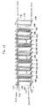
- Fig. 12 is an exploded view showing the structure of the electrodeionization apparatus.
- the electrodeionization apparatus includes a cathode end plate 101, a cathode 102 extending along the end plate 101, a cathode spacer 103 extending along the outer periphery of the cathode 102 which are superposed in this order. Further, a cation-exchange membrane 104, a frame 105 for defining a diluting compartment, an anion-exchange membrane 106, and a frame 107 for defining a concentrating compartment are superposed on the cathode spacer 103 in this order.
- the cation-exchange membrane 104, the frame 105 for defining a diluting compartment, the anion-exchange membrane 104, the frame 107 for defining a concentrating compartment compose one unit.
- the apparatus is composed of a plurality of such units superposed together. That is, membranes 104, frames 105, membranes 106, and frames 107 are repeatedly superposed one unit over the other unit. An anode 109 is superposed between the last anion-exchange membrane 106 and an anode spacer 108. An anode end plate 110 is superposed on the anodic electrode 109.
- the apparatus is tightened by bolts or the like.
- the space defined by the inner surface of the frame 105 is the diluting compartment in which an ion exchanger 105R such as ion-exchange resin is filled.
- the space defined by the inner surface of the frame 107 is the concentrating compartment in which a spacer including a mesh spacer is disposed.
- a direct electric current is supplied to pass between the anode 109 and the cathode 102, raw water to be treated is fed to the diluting compartment through a raw water inlet line 111, and feed water is fed to the concentrating compartment 108 through a concentrate inlet line 112.
- the raw water fed to the diluting compartment flows through a layer filled with the ion-exchange resin whereby impurity ion in the raw water is removed so as to make the raw water to deionized water which flows out through a deionized water outlet line 113.
- the impurity ions permeate the membranes 104, 106, the concentrated water in the concentrating compartment flows out through a concentrate outlet line 114. Electrode water is passed within electrode compartments through introducing lines 115, 116 and discharging lines 117, 118, respectively.
- JP4-72567B An electrodeionization apparatus in which a diluting compartment is provided with vertical partition ribs for dividing the diluting compartment into cells being long in the vertical direction is disclosed in JP4-72567B.
- this electrodeionization apparatus having the diluting compartment divided into long cells by ribs in which ion-exchange resins are filled respectively, the channelizing phenomenon where the flow of water from the inlet to the outlet of the diluting compartment is partially one-sided is prevented and the compression and the ion-exchange resins in the diluting compartment is prevented from being compressed or moved.
- the number of the cells is limited because the cells are formed by dividing the diluting compartment in the vertical direction. That is a large number of cells can not be formed in the apparatus. Further, the flow of the water in a lateral direction is blocked by the ribs, so that the contact efficiency between the water and the ion-exchange resins is poor. In addition, the ion-exchange resins are compressed at lower portions of the cells so that the cells have a vacancy at upper portions thereof, whereby the rate of filling the ion-exchange resins tends to be poor.
- Fig.4 is a system diagram showing a conventional apparatus for producing purified water provided with the electrodeionization apparatus in which raw water such as the city water is treated in an activated carbon treating device 1, a reverse osmosis membrane treating device 2, and an electrodeionization apparatus 3.
- the conventional electrodeionization apparatus can completely remove weakly - ionized species having low dissociation constant (pKa) such as CO 2 by increasing the applied voltage to dissociate water.
- the conventional electrodeionization apparatus scarcely removes weakly - ionized species having high dissociation constant such as silica and boron on the order 60 to 90% even when the applied voltage is increased.
- the diluting compartments filled with multi - layered ion exchangers can not lower the concentration of silica to less than 0.1ppb as required in the fields of the semiconductor manufacturing and the like.
- an electrodeionization apparatus of non - regenerative mixed bed type is necessary after the electrodeionization apparatus because the water treated by the electrodeionization apparatus includes silica and boron of 0.5 to 1.0ppb or more.
- H + ion has mobility of 349.7 cm 2 ⁇ -1 eq -1 , which is very large in comparison with that of the other ions (30 to 70 cm 2 ⁇ -1 eq -1 ,ref ; Manual of Chemistry published by Japanese Chemical Society). Therefore, particularly when the diluting compartment has a large thickness W, the difference of the mobilities between H + and OH - is increased so that H + tends to be quickly discharged to the concentrating compartments and OH - tends to remain in the diluting compartment.
- Na + and K + also tend to remain in the diluting compartments because these are monovalent and H + ion carryies the electrons, while the multi-valent cations and anions including Ca 2+ , Mg 2+ are discharged to the concentrating compartments with relative ease.
- the product water tends to include monovalent alkali such as NaOH and KOH so that the product water (deionized water) becomes alkaline.
- the electrodeionization apparatus of the present invention has an anode, a cathode, concentrating compartments, and diluting compartments which are formed by arranging a plurality of anion exchange membranes and cation exchange membranes between the anode and the cathode, ion exchangers filled in the diluting compartments.
- the electrodeionization apparatus can produce the product water having pH higher than pH of the feed water by 1.0 or more when the feed water having pH of equal to or less than 8.5 is treated without adding alkaline agent.
- the electrodeionization apparatus of the present invention efficiently removes the weakly - ionized species including silica, boron from the feed water.
- the apparatus for producing purified water of the present invention is provided with plural stages of the electrodeionization apparatuses through which the feed water flows in order.
- the foremost electrodeionization apparatus is the electrodeionization apparatus of present invention.
- the foremost electrodeionization apparatus removes a part of carbon dioxide gas, silica, boron and the hardness from the feed water.
- the water treated in the foremost electrodeionization apparatus has the same in conductivity as the feed water and higher pH than the feed water.
- the water treated by the foremost apparatus is then treated by conventional electrodeionization apparatus to remove the residual silica, boron and the other ions.
- the electrodeionization apparatus behaves specifically. That is, when the water including a small amount of alkaline metal ion or alkaline earth metal ion which are taken out of a reverse osmosis apparatus (RO apparatus) flows through the electrodeionization apparatus, the carbon dioxyde gas (CO 2 ) and the anion in the water are removed, besides about 90% of silica and boron are removed.
- RO apparatus reverse osmosis apparatus
- the monovalent cations including Na + and K + have difficulty in being removed and the alkalis such as NaOH and KOH which have high molar conductivity leak into the treated water so that the treated water tends to be increased in pH and slightly in conductivity.
- H + ion has mobility of 349.7 cm 2 ⁇ -1 eq -1 , which is very large in comparison with that of the other ions (30 to 70 cm 2 ⁇ -1 eq -1 ,ref ; Manual of Chemistry published by Japanese Chemical Society).
- the product water tends to include monovalent alkali such as NaOH and KOH so that the product water is increased in pH.
- the electrodeionization apparatus is free of scale even when the matters such as Ca 2+ and Mg 2+ are concentrated at high conentration.
- the electrodeionization apparatus of the present invention may be provided with a cation exchange membrane between the anode and the anion exchange membrane of the diluting compartments nearest to the anode, so that the concentrating compartments is formed between the cation exchange membrane and the diluting compartment nearest to the anode, and the anodic compartment is formed between the cation exchange membrane and the anode.
- the cation concentration in the cathodic compartment is high and the electric resistance between the electrodes is low, whereby the voltage applied to cells is decreased.
- the electrodic water fed into the cathodic compartment is decreased in pH (or, the electrodic water is made acidic).
- the thickness of the diluting compartment is increased to decrease pH of the water which flows out from the concentrating compartments and then flows into the cathodic compartment as the elecrtrode water.
- the electrodeionization apparatus of the present invention is useful for a foremost electrodeionization apparatus of the apparatus for producing purified water in which two or more electrodeionization apparatuses are connected in series so as to make treatment of the feed water at plural stages.
- feed water having conductivity of 10 ⁇ S/cm and including silica 200ppb and boron of 20ppb flows through the first electrodeionization apparatus of the present invention and then flows through the second conventional electrodeionization apparatus, the water flowing out from the second electrodeionization apparatus has electrical resitivity of equal to or more than 18 M ⁇ ⁇ cm and includes silica and boron of equal to or less than 0.1ppb as like as the theoretical pure water.
- the succeeding second electrodeionization apparatus Since the preceding first electrodeionization apparatus removes the hardness such as Ca 2+ and Mg 2+ , the succeeding second electrodeionization apparatus is free of scale and has the water recovery of equal to or more than 95%.
- the concentrating compartment of the preceding first electrodeionization apparatus produces the acidic water and the concentrating compartment of the succeeding electrodeionization apparatus produces the alkaline water. These acidic water and alkaline water may be mixed together and be fed back to the preceding RO apparatus.
- the electrodeionization apparatus of the present invention may be provided with thick cells having a thickness of equal to or more than 7 mm and thin cells having a thickness of less than 7 mm as shown in Fig.7 and Fig.8 so that the water flows through from the thick diluting compartment to the thin cell in series.
- the electrodeionization apparatus of the present invention is so constituted that the electrodeionization apparatus can produces the product water having pH higher than that of the feed water by 1.0 or more, preferably by about 1.3 to 3.0 when the feed water has pH of equal to or less than 8.5 without adding alkaline agents.
- the electrodeionization apparatus of the present invention efficiently removes the weakly - ionized species including silica and, boron, and the hardness by increasing pH of the water in the electrodeionization apparatus.
- the electrodeionization apparatus of the present invention is preferable to employ the following constitutions i) and ii):
- the electrodeionization apparatus wherein a certain zone in the diluting compartment is filled with the cation exchanger and the other zone in the diluting compartment is filled with the cation exchanger is unpreferably increased in resistivity of the product water and makes pH thereof neutral even when the thickness of the diluting compartment is more than 7mm. This is because the monovalent cation including sodium ion is removed by the cation exchanger.
- the ion exchangers may be filled in the concentrating compartments in the first, second or later electrodeionization apparatus, whereby the voltage applied to the cells may be decreased so that the electric power consumption decreases.
- the ion exchangers may be the ion exchange resin in the form of beads or fibers, the graft polymerized exchanger in which exchanging groups are introduced into fibers or nonwoven sheet by graft porymerization, or the like.
- the ion exchanger is preferable to be in the form of the beads having uniform size.
- the bead-shaped ion exchange resin represents that 90% of the beads fall within 10% of the average bead diameter and the relative average diameter between the anion exchange resin and the cation exchange resin is at least 0.8.
- the cells of the diluting compartments are applied with the voltage at 1 to 50 V per cell, preferably at 6 to 50 V per cell, most preferably at 10 to 30 V per cell.
- the water flows at a space velocity (SV) of 30 to 150 per hour, preferably at SV of 50 to 100 per hour.
- SV space velocity
- the diluting compartments having uneven cells can make pH equal to or more than 9 in the diluting compartments. Specifically, the rate of the thickness of the cell near the out let to the maximum thickness of the cell is equal to or less than 0.6.
- the ion exchange membrane employed in the present invention may be either homogeneous or heterogeneous, the rate of leakage of Na + of the heterogeneous membrane exceeds that of the homogeneous membrane, so that the product water is increased in pH. Therefore, the cation membrane is preferable to be heterogeneous.
- the anion membrane is preferable to be homogeneous so as to maintain the removing rate of silica and boron.
- the electrodeionization apparatus having aforementioned constitutions in which the diluting compartments having a thickness of 10 to 20 mm is filled with the mixture of the anion exchange resin and the cation exchange resin, the water flows at SV of 50 to 100 per hour and the applied voltage is taken as 10 to 30V per cell, the hardness is removed by more than 50% and the weakly - ionized species including the silica and the boron are removed by more than 90%.
- the electrodeionization apparatus may have the same structure as the conventional electrodeionization apparatus except for the aforementioned constitutions.
- the water to be fed into the electrodeionization apparatus of the present invention is preferable to be the water containing silica and/or boron prepared by treating the tap water, the river water, the ground water and the like with the reverse osmosis membrane apparatus.
- the electrodeionization apparatus of the present invention is preferably operated in such a condition that the scale index SI is 500 or less.
- the inventors of this invention conducted experiments for making clear the forming mechanism of scales in the electrodeionization apparatus.
- scales were intentionally formed by mixing excessive amounts of inorganic carbononate and Ca 2+ in feed water to the electrodeionization apparatus. After that, the apparatus was disassembled and the concentrating compartment was observed. As a result, it was found that calcium carbonate adhered to the anion-exchange membrane at the concentrating compartment side.
- the inventors presumed that the forming mechanism of scales was follows. That is, when the electrodeionization apparatus is in operation, pH near a surface of the anion-exchange membrane locally become alkaline. CO 3 2- or HCO 3 - and OH - permeating the anion-exchange membrane from the diluting compartment are concentrated near the anion-exchange membrane. In addition, Ca 2+ in water in the concentrating compartment is drawn or driven to the anion-exchange membrane, so that CO 3 2- or HCO 3 - and OH - react with Ca 2+ to form scales of calcium carbonate on the anion-exchange membrane.
- the inventors further studied and found that no scale forms when the scale index SI obtained by multiplying the load per unit area of inorganic carbonate of the anion-exchange membrane by the Ca 2+ concentration in concentrated water is 500 or less.
- the load of inorganic carbonate (mg-CO 2 /hr) of the electrodeionization apparatus is obtained by multiplying the inorganic carbonate concentration (mg-CO 2 /L) of water fed to the electrodeionization apparatus by the flow rate (L/hr).
- the load of inorganic carbonate per unit area (mg-CO 2 /hr ⁇ dm 2 ) is the product of [the inorganic carbonate concentration (mg-CO 2 /L) of feed water] and [the flow rate per cell(L/hr) / the effective area of cells of the anion exchange membrane (dm 2 )].
- the scale index SI By controlling the scale index SI to be 500 or less, preferably 200 or less, precipitation of scales of calcium carbonate can be securely prevented in the concentrating compartment of the electrodeionization apparatus, thus enabling the stable operation of the electrodeionization apparatus for a long period of time.
- the SI not exceeding 200 is enough, when the required removing rate of silica is less 90% or when the current efficiency during its operation exceeds 20%.
- the SI is preferably in a range between 80 and 200 to avoid treatment by a degassing apparatus, a softener, and/or such other extra device.
- the SI is preferably is 120 or less, particularly 80 or less. In view of economic consideration, the SI is preferably in a range between 50 and 120.
- the permissible SI is 80 or more even preferably 80-200 when the electric current is increased.
- the more preferable SI in this case is in a range between 80 and 150. If economic consideration is not taken, SI lower than 80 is also permissible.
- One of the methods is to lower the Ca 2+ concentration in the concentrated water by removing Ca 2+ by lowering the recovery of water or by the use of a Ca 2+ removing device such as a softener.
- Another method is to lower the load on the membrane surface of the inorganic carbonate by reducing the amount of the water to be treated in the electrodeionization apparatus or removing inorganic carbonate by the use of a degassing device disposed at upstream of the electrodeionization apparatus.
- Alternative method of lowering the load on membrane surface of inorganic carbonate is to control the electric current of the electrodeionization apparatus.
- the conductivity of water in the concentrating compartment should be high, thereby achieving excellent quality of treated water.
- Water to be treated having CO 2 concentration of 10 ppm or less may be passed through a reverse osmosis apparatus before being introduced into the electrodeionization apparatus of the present invention.
- the conductivity of the water in the concentrating compartments is preferable to be equal to or more than 50 ⁇ S/cm.
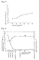
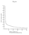
- the interrelationship between the conductivity and the elecrical resistance of the concentrated water in the electrodeionization apparatus is shown in Fig.14.
- Fig.14 shows that the electrical resistance increases rapidly as the conductivity falls below 50 ⁇ S/cm. Therefore, the conductivity of at least 50 ⁇ S/cm is required at the outlet of the concentrating compartments to ensure the electrical current. When the conductivity is below 50 ⁇ S/cm, the electrical resistance would increase to raise the electric cost.
- Fig.1 and Fig.2 are invention respectivery according to and embodiment.
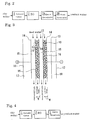
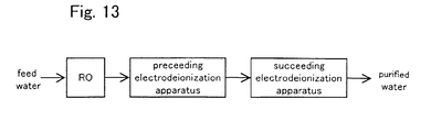
- the apparatus for producing purified water shown in Fig.1 is provided with a RO apparatus 2, a first preceding electrodeionization apparatus 3A and a second succeeding electrodeionization apparatus 3B which are connected in series.
- the apparatus for producing purified water shown in Fig.2 is provided with an activated carbon apparatus 1, RO apparatus 2, the preceding electrodeionization apparatus 3A, and the succeeding electrodeionization apparatus 3B which are connected in series.
- the preceding electrodeionization apparatus 3A is related to the present invention mentioned above.
- the succeeding electrodeionization apparatus 3B is conventional electrodeionization apparatus.
- the thickness of the diluting compartments of the succeeding electrodeionization apparatus 3B is preferable to be smaller than that of the preceding electrodeionization apparatus 3A and to be in the range of 2.0 to 6.0mm.
- any one of the succeeding electrodeionization apparatus may be that of the present invention, so that the purified water producing apparatus becomes to have a high flow rate and the purified water producing apparatus becomes compact in its constitution.
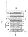
- the electrodeionization apparatus of the present invention may have diluting compartments, each of which is divided into a plurality of cells by a partition member, and an ion exchanger is filled in the respective cells. At least a part of the partition member facing the cell is inclined relative to a normal flow direction of the water in the diluting compartment. The inclined part of the partition member allows permeation of the water, but prevents the ion exchanger to pass therethrough. Therefore, at least a part of the water flowing into the diluting compartment should flow obliquely relative to the normal flow direction of water, so that the water is dispersed overall the diluting compartment, thereby improving the contact efficiency between water and ion exchanger and improving the deionization property.
- the water flows in the cells with being stirred by the inclined part of the member, so that a boundary layer of concentration along the surface of the membrane whereby a dispersion resistance of ions is lowered and the apparatus becomes possible to be operated with a high flow velocity.
- the apparatus has a large number of cells are arranged vertically and laterally.
- a plurality of cells are arranged along the membrane surface both in the normal flow direction of water and a direction perpendicular to the normal flow direction, thereby extremely improving the contact efficiency between water and ion exchanger. Since the height of each cell is low, the ion exchanger is scarcely compressed. A vacancy is not formed at an upper portion in the cell, and the cell is filled evenly with the ion exchanger.
- each cell seen by projecting it upon the surface of the membrane is preferably a hexagon or a quadrangle.
- the cells are preferably arranged in such a manner that a pair of sides thereof extend in the normal flow direction of water.
- the cells are preferably arranged in such a manner that the respective sides thereof extend obliquely relative to the normal flow direction of water.
- All of the cells may be filled with the same ion exchanger, or instead thereof some of the cells may be filled with ion exchanger different from the ion exchanger filled in the other cells.
- an anion exchanger may be filled in first cells
- a cation exchanger may be filled in second cells
- an amphoteric ion exchanger (or a mixture of the anion exchanger and the cation exchanger) may be filled in third cells.
- This electrodeionization apparatus may be installed at the succeeding stage of the purified water producing apparatus of the present invention, whereby monovalent cations such as Na + leaked from the preceding stage are removed by the succeeding electrodeionization apparatus even when the feed water is fed at a high rate.
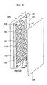
- Fig. 9 is an exploded perspective view showing the structure of a diluting compartment according to another embodiment
- Fig. 10 is a front view illustrating the water flowing condition of the partition member.
- the diluting compartment comprises a rectangular frame 120, a partition member 121, preferably having conductivity, disposed in the frame 120, an ion exchanger 123 filled in cells 122 formed by the partition member 121, an anion-exchange membrane 124 and a cation exchange membrane 125 which are disposed to sandwich the frame 120.
- the partition member 121 may be electrically-conductive.
- the frame 120 is provided with a flow inlet 126 for introducing raw water to be treated and a flow inlet 127 for concentrated water in an upper portion thereof and with a flow outlet 128 for deionized water and a flow outlet 129 for concentrated water formed in a lower portion thereof.
- the flow inlet 126 and the flow outlet 128 are connected to the inside of the frame 120 through a notch-like channels 126a, 128a, respectively.
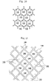
- the partition member 121 is in a honeycomb form of a hexagonal shape in which a large number of cells are arranged in vertical and lateral directions in such a manner that a pair of sides of each cell 122 extend in the longitudinal direction of the frame 120, i.e. in the vertical direction.
- the vertical surfaces 131 may be permeable or not permeable to water.
- the other structure of the electrodeionization apparatus having this diluting compartment is the same as that of the aforementioned conventional one of Fig. 12 and the flow passages for raw water, concentrated water, and electrode water are also the same as those of the conventional one.
- a cathode compartment is formed and defined by the cathode, the cathode spacer, and the cation-exchange membrane.
- the deionizing operation is conducted by passing raw water through this electrodeionization apparatus
- the raw water introduced into the diluting compartment permeate the partition member 121 surrounding the cells 122 so as to flow into adjacent cells 122 and thus gradually flows downwardly.
- the water is deionized.
- the water reaches the bottom of the diluting compartment and flows out to the flow outlet 128 through the channels 128a.
- the flow outlet 128 the water is took out from the electrodeionization apparatus as the deionized water.
- the general direction of water in the diluting compartment is a downward vertical direction because the channels 126a for introducing raw water exist at the top of the frame 120 and the channels 128a for taking out the deionized water exist at the bottom of the frame 120.
- the partition 121 is inclined relative to the general direction of water exist at upper portions and lower portions of the respective cells, so that the water flows obliquely and downwardly from one cell 122 into the lower left cell 122 and the lower right cell 122. Therefore, the water flows substantially uniformly to all cells 122, thereby improving the contact efficiency between the water and the ion exchanger.
- ion exchanger to be filled in the cells 122 may be an anion exchanger, a cation exchanger, an amphoteric ion exchanger, or a mixture of at least two of them.
- the cells are hexagonal in Figs. 9 and 10, the cells may be quadrangular e.g. rhombic just like cells 145 shown in Fig. 11.
- the projected area to the ion exchange membrane of the cells is preferably 1-100 cm 2 , particularly 2-50 cm 2 , more particularly 3-10 cm 2 .
- the size of the cells is reduced, the amount of the ion exchanger to be filled in one cell is reduced so that the fluidization of the ion exchanger is restrained.
- the strength of the partition member and the strength of the diluting compartment are increased.
- the pressure loss of the water flowing in the diluting compartment is increased.
- the ion exchanger to be filled is normally an ion exchange resin.
- the ion exchanger may be an ion exchange fiber, ion exchange non-woven fabric, or a mixture of an ion exchange resin and an ion exchange fiber.
- Ion conductor such as conductive resin may be employed.
- the preceding electrodeionization apparatus 3A removes the weakly - ionized species including silica, boron, and the hardness, and the succeeding electrodeionization apparatus 3B further removes silica and boron.
- the succeeding electrodeionization apparatus 3B removes the alkalis leaked from the preceding electrodeionization apparatus 3A, the product water becomes high quality.
- the water to be fed into the preceding electrodeionization apparatus is preferable to contain Na + of equal to or more than 0.1ppm as Na + .
- the water is preferably added with NaCl.
- the feed water needs to contain Na + ion.
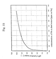
- the relationship between the concentration of Na + in the feed water and pH of the product water is shown in Fig.15.
- the concentration of Na + is required to be equal to or more than 0.1 ppm as Na + , preferably in the range of 0.5 to 4 ppm as Na + .
- the concentration of CO 2 in the water to be fed into the preceding electrodeionization apparatus is preferable to be equal to or less than 3ppm as CO 2 .
- the removing rates of silica and boron decrease.
- concentration of CO 2 exceeds 3ppm, it is preferable to remove CO 2 by the use of a degassing apparatus installed in the upstream or by increasing pH of the water fed into the RO apparatus to 8 or more to form HCO 3- .
- the water recovery rate of preceding electrodeionization apparatus 3A is preferable to be 60 to 90%. Even when the water recovery rate of succeeding electrodeionization apparatus 3B is equal to or more than 95%, for example the rate is in the range of 95 to 99%, the product water of good quality is produced without causing scale.
- the electrical voltage and current applied to the preceding electrodeionization apparatus 3A are increased, pH of the water treated in the preceding electrodeionization apparatus becomes high. Therefore, it is preferable to observe pH by installing a pH meter 4 to the pipe for discharging the treated water from preceding electrodeionization apparatus 3A and to control the voltage and the current applied to the preceding electrodeionization apparatus 3A so that the value of pH becomes preferably equal to or more than 8.5, more preferably between 9.0 and 10.5.
- the preceding electrodeionization apparatus 3A is preferable to remove Na + at a rate of less than 90% and the chloride ion of more than 95%. When the chloride removing rate is more than 95%, pH becomes high.
- a resistivity meter 5 and a silica meter 6 are installed to the pipe for discharging the product water from the succeeding electrodeionization apparatus 3B in order to observe the resistivity and the concentration of silica of the water product in the succeeding electrodeionization apparatus 3B, and the voltage and the current applied to the apparatus 3A and /or the apparatus 3B are controlled so that the resistivity and the concentration of the silica are in the sights.
- the electrodeionization apparatuses 3A, 3B are operated at A/(Q ⁇ SV) of equal to or more than 4000, the removing rates of the silica and the boron are increased.
- the removal rate of silica is closely related to the value of A/(Q ⁇ SV).
- A/(Q ⁇ SV) of 4000 or more can achieve the silica removing rate of 97% or more.
- the apparatus for producing purified water of the present invention may by provided with a RO apparatus, a degassing apparatus where the permeating water passing thorough the RO apparatus is introduced, and the electrodeionization apparatus where the water treated in the degassing apparatus is introduced. It is preferable that the feed water having M - alkalinity expressed as CaCO 3 of more than 20 ppm and pH of or more than 6.5 is fed to the RO apparatus, and that the water having pH of less than 6.2 is taken out from the RO apparatus and fed into the degassing apparatus.
- the degassing apparatus is a membrane degassing apparatus and the water to be introduced to the degassing apparatus has TOC of less than 200ppb or conductivity of less than 20 ⁇ S/cm.
- the M - alkalinity is the feed water is removed by the RO apparatus, so that the permeating water thereof has low pH.
- the water having low pH is efficiently removed in CO 2 by the degassing apparatus, so that the electrodeionization apparatus can be reduced in the load of CO 2 . loaded thereon.
- the ability to remove CO 2 can be improved by 30 to 50% by degassing the water which is decreased in pH by treating with the RO apparatus in comparison with the case where the water is degassed before the treatment with the RO apparatus.
- the degassing apparatus arranged behind the RO apparatus can stabilize the ability to degas for a long period of time.
- the RO apparatus removes salts and TOC (total organic carbon), so that a slime defects caused by the salts and the TOC are avoided.
- the feed water into the membrane degassing apparatus has the TOC concentration of less than 200ppb, and/or the electric conductivity of 20 ⁇ S/cm in order to prevent the membrane from contamination and to stabilize the degassing ability for a long period.
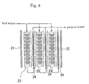
- the reject water of the RO apparatus 2 is discharged as the drain and the permeated water of the RO apparatus 2 is distributed and fed into the electrodic compartment 3Aa, the diluting compartments 3Ab and concentrating compartments 3Ac of the preceding electrodeionization apparatus 3A respectively.
- the product water of the preceding electrodeionization apparatus 3A (the water flowing out from the diluting compartments 3Ab) is distributed and fed into the electrodic compartment 3Ba, the diluting compartments 3Bb and the concentrating compartments 3Bc of the succeeding electrodeionization apparatus 3B respectively.
- the water flowing out from the diluting compartments 3Bb is discharged as the product water.
- the water flowing out from the electrodic compartments 3Aa and 3Ba is discharged as the drain.
- the concentrated water flowing out from the concentrating compartments 3Ac of the preceding electrodeionization apparatus 3A is acidic, and the concentrated water flowing out from the concentrating compartments 3Bc of the succeeding electrodeionization apparatus 3B is alkaline. Therefore, it is preferable that the concentrated water flowing out from the concentrating compartments 3Ac and 3Bc are mixed and returned to the inlet portion of the RO apparatus 2.
- the concentrated water of either preceding electrodeionization apparatus 3A or succeeding electrodeionization apparatus 3B may be independently fed back to the front stage of the RO apparatus 2.
- the concentrated water of the succeeding electrodeionization apparatus 3B may be fed back to the inlet portion of the preceding electrodeionization apparatus 3A.
- the electrodeionization apparatus shown in Fig.1 and Fig.2 has one electrodeionization apparatus 3B, the electrodeionization apparatus may be provided with two or more electrodeionization apparatuses 3B which are connected in series.
- cells 23 of more than 7mm in the thickness of diluting compartments and cells 24 of less than 7mm in the thickness of the diluting compartments may be arranged between an anode 21 (or 21A, 21B) and a cathode 22 so that the fed water flows through these cells in series.
- the electrodeionization apparatus of the present invention is preferably operated so that the concentration of silica of the concentrated water flowing out from the concentrating compartments of the second or later electrodeionization apparatus is less than one thousand times as high as that of the produced water of the electrodeionization apparatus.
- the concentration of silica of the concentrated water is preferable to be decreased to 100ppb or less.
- the apparatus for producing purified water may be composed of a RO apparatus, a first electrodeionization apparatus and a second electrodeionization apparatus so that the water firstly flows from a reverse osmosis membrane apparatus into the first apparatus and then flows into the second electrodeionization apparatus wherein the reverse osmosis membrane apparatus consists of the reverse osmosis membrane having the degree of desalination of monovalent salts of equal to or less than 97%.
- the degree of desalination of monovalent salts will be simply called as “the degree of the desalination”.
- the electrical resistance rapidly increases as the conductivity of the concentrated water of the electrodeionization apparatus falls below 50 ⁇ S/cm.
- the conductivity of more than 50 ⁇ S/cm, preferably more than 75 ⁇ S/cm reduces the electrical resistance and sufficiently ensures the electrical current required for deionization in the electrodeionization apparatus.
- the concentrated water can be provided with the conductivity of roughly 75 ⁇ S/cm or more in operation employing the usual raw water and the usual water recovery and the electricalent can be ensured in the electrodeionization apparatus.
- the present invention it is very important to feed the permeating water obtained by treating the feed water by RO membrane having realtively low degree of desalination into the diluting compartments since the conductivity of the concentrated water can not be ensured when the permeating water is fed into the concentrating compartments alone, and the results prevent decrease of the electrical resistance and improvement of the electrical current.
- the RO membrane preferably has the removal rate of the hardness and silica of equal to or more than 97%. That is, the hardness such as by Ca 2+ and silica easily form scales in the electrodeionization apparatus and require the appreciably electrical current to remove the scales. Therefore, the hardness and silica are preferably removed in the RO apparatus preceding the electrodeionization apparatus, so that the RO membrane having the removal rate of the hardness and silica of more than 97% is preferable to be employed.
- the RO membrane mentioned above may be commercially saled one. It may be prepared by being treated with oxidizer so that the RO membrane becomes hydrophilic and has the degree of desalination of equal to or less than 97% and the removal rate of silica of equal to or more than 97%.
- the electrodeionization apparatus is preferably provided with the diluting compartments having a thickness of equal to or more than 7mm.
- the conductivity of the product water is almost same as of the fed water or slightly larger than it, while carbon dioxide gas (CO 2 ) and anions are removed and about 90% of silica and boron are also removed.
- the hardness including Ca 2+ , Mg 2+ is further removed.
- the electrodeionization apparatus is increased in the conductivity of the concentrated water by employing the RO membrane having the degree of desalination of monovalent salts represented by NaCl of equal to or less than 97 % to leak the monovalent salts into the RO permeating water so that the permeated water is fed into the diluting compartments of the electrodeionization apparatus.
- the degree of desalination of RO membrane exceeds 97%, the aforementioned effect is not sufficiently achieved.
- RO membrane is preferably to have the degree of desalination especially of 90 to 95 %.
- the RO membrane as the above may employ a membrane being marketed as low desalination membrane, for example a membrane called as a loose RO membrane and a nano - filtration (NF membrane) membrane, specifically, "LES 90" and “NTR-729HF” produced by Nitto Electrical Industry Co., Ltd.
- the RO membrane is also preferably to have the removal rate of the hardness and silica, more preferably besides the removal and silica, more preferably besides the removal rate of TOC (total organic carbon) of equal to or more than 97 %.
- the electrodeionization apparatus is preferable to be provided with the diluting compartments having a thickness of equal to or more than 7mm, particularly of 8 to 30mm.
- the ion exchanger is most preferable to be a mixture of the anion exchanger and the cation exchanger.
- a single layer comprising the anion exchanger alone can being the same effect as the mixture.
- a combination of the mixture and the anion exchanger may be employed.
- an ultraviolet - light irradiating apparatus may be installed between electrodeionization apparatuses to decompose TOC in the water.
- the ultraviolet - light irradiating apparatus decompose TOC at high efficiency.
- hydrogen peroxide or ozone having concentration of 2 to 20 times as high as the concentration of TOC in the water is added into the product water, the efficiency of decomposition is further increased.
- a first RO apparatus may be installed before the preceding electrodeionization apparatus, and a second RO apparatus may be installed between the preceding electrodeionization apparatus and the succeeding electrodeionization apparatus.
- the RO apparatus By using the RO apparatus, silica and boron are easily removed from the alkaline feed water. Since the product water flowing out from the preceding electrodeionization apparatus is alkaline without adding alkalis including NaOH, the second RO apparatus easily removes silica and boron from the product water.
- the second RO apparatus when the water flowing into the second RO apparatus has pH of 7, the second RO apparatus removes 99% of silica and 70% of boron in the water.
- the second RO apparatus removes 99.9% of silica and 97% of boron.
- the feed water fed into the preceding electrodeionization apparatus may be regularly added with salts including NaCl so that silica accumulated in the electrodeionization apparatus can is discharged therefrom.
- Fig.15 shows an example of the interrelationship between pH values of the feed water fed into the preceding electrodeionization apparatus and the product water flowing out from the therefrom.
- the concentrated water of the preceding electrodeionization apparatus becomes acidic and the concentrated water of the succeeding electrodeionization apparatus becomes basic without adding agents so that the slime is not be formed in the concentrating compartments.
- the concentrated water of the preceding electrodeionization apparatus is decreased in number of the living bacteria to 100 per milliliter and the concentrated water of the succeeding electrodeionization apparatus is decreased in number of the living bacteria to 0 per milliliter.
- the alkaline chemicals may be added into the water between the first and second stages or the inlet of the first stage. Even when pH of the water is not sufficiently increased at the first stage, the treatment with the second or later electrodeionization apparatus improves the removal rate of silica.
- the feed water fed into the first electrodeionization apparatus is preferable to have pH of equal to or more than 9.5 in order to efficiently remove the weakly - ionized species including silica and boron by the second or later electrodeionization apparatus.
- the removal rate of silica is 99% when the feed water fed into the secondary electrodeionization apparatus has pH of 9.0, the removal rate of silica is 99.9% when the feed water fed into the secondary electrodeionization apparatus has pH of 9.5.
- the Ca 2+ concentration in the feed water is preferable to be equal to or less than 30ppb, more preferable to be equal to or less than 5ppb as Ca 2+ since the water flowing in the concentrating compartments and the electrodic compartment is alkaline.
- the basic feed water causes the scale of CaCO 3 in the concentrating compartments and the electrodic compartment. Therefore, Ca 2+ is required to be removed at the first stage.
- Example 1 shows the apparatuses used in Examples and Comparative Examples.
- the apparatuses are arranged as shown in Fig.4 to be connected in series.
- Example 6 the apparatus including two electrodeionization apparatuses are arranged as shown in Fig. 2 to be connected in series.
- An electrodeionization apparatus is assembled as shown in Fig.3 in which the following ion exchange membranes are employed and the diluting compartments are filled with mixture of 6 parts by volume of the following anion exchange resin and 4 parts by volume of the following cation exchange resin.
- the anion exchange resin and the cation exchange resin are sufficiently washed by ultra pure water before being filled in the diluting compartments.
- Each of the diluting compartments has a thickness of 2.5 mm and consists of 12 cells.
- the water is fed into the electrodeionization apparatus under conditions as shown in Table 1.
- the resistivity of the product water, the concentration and the removal rate of silica, boron and the other ions are measured and results are shown in Table 1.
- Anion exchange membrane "Neosepta AHA” produced by Tokuyama Co,. Ltd.
- An electrodeionization apparatus is assembled to conduct the treatment in the same manner as comparative example 1 except that each of the diluting compartments has thickness of 10 mm and consists of three cells, and the water is fed under conditions as shown in Table 1.
- the resistivity of the product water, the concentrated and the removal rate of silica, boron and the other ions are shown Table 1.
- the CO 2 concentration of the feed water and the CO 2 concentration of the water treated by the preceding electrodeionization apparatus 3A are measured to calculate the removal rate.
- the removal rate is 90%
- the removal rate is 60% or less.
- Example 1 by employing the heterogeneous membrane for the ion exchange membrane, the removing rate of Na + decreases from 46% to 40% and pH increases from 9.5 to 9.65.
- Electrodeionization apparatuses are assembled in the same manner as Comparative Example 1 except that the diluting compartments of those respectively have thickness as follows.
- the water is treated under the same conditions as Comparative Example 1 except that the water is fed at SV of 60 per hour, and the electric voltage as the current efficiency falls in the range of 10 to 20%.
- the resistivity and pH of the product water are shown in Fig.6.
- the activated carbon apparatus 1, the RO apparatus 2 and the electrodeionization apparatus 3A, 3B are arranged in this order to be connected in series wherein the preceding electrodeionization apparatus 3A is the same electrodeionization apparatus provided with the diluting compartments having a thickness of 10mm as Example 1 and the succeeding electrodeionization apparatus 3B is the same electrodeionization apparatus provided with the diluting compartments having thickness of 2.5mm as Comparative Example 1.
- the feed water is fed into the apparatus under conditions as shown in Table2.
- the quality of the product water (flowing out from the electrodeionization apparatuses 3A, 3B respectively) are shown in Table2.
- the electrodeionization apparatus of Example 1 provided with the diluting compartments having a thickness of 10mm slightly exceeds the electrodeionization apparatus of Comparative Example 1 provided with the diluting compartments having a thickness of 2.5mm in the removal rate of silica and boron. Calcium is almost entirely removed.
- pH of the product water increases as the applied voltage increases.
- the cells are applied with the voltage at 8V per cell, and in the succeeding electrodeionization apparatus 3B the cells are applied with the voltage at 3V per cell.
- the cells of the preceding electrodeionization apparatus are applied with the voltage of 15V and those of the succeeding electrodeionization apparatus are applied with the voltage of 4.5V.
- Table 2 shows that when the water is firstly treated in the electrodeionization apparatus provided with the diluting compartments having a thickness of 10mm and then fed into the electrodeionization apparatus provided with the diluting compartments having a thickness of 2.5mm, the concentration of silica and boron is lowered to the limit of analytic detection, and the product water of very good quality (pH 7 and the resistivity of 18.2 M ⁇ ⁇ cm) can be contained.
- the purified water producing apparatus shown in Fig.13 is assembled.
- the succeeding electrodeionization apparatus relates to the present invention which is provided with the cells having honeycomb structure in the diluting compartments.
- the product water flown out of the preceding electrodeionization apparatus is of the following quality:
- the succeeding electrodeionization apparatus is substituted for the conventional electrodeionization apparatus provided with ribs in the diluting compartments.
- the measuring conditions are as follows.
- the cells of the electrodeionization apparatus Hexagonal form, the area of which is 3.9 cm 2 .
- Ion exchange resin of the diluting compartments SA 10A of anion resin and SK 1B of cation resin; both of which are produced by Mitsubishi Chemical Corporation; (including 6 parts of the anion exchange resin and 4 parts of the cation exchange resin)
- Ion exchange membrane AHA (anion exchange membrane), CMB (cation exchange membrane) produced by Tokuyama Co., Ltd.
- Example 7 (For comparison) number of cells 4 12 thickness of diluting compartment (mm) 5.0 2.5 height of cell (cm) 400 600 Space velocity (hr -1 ) 120 60 voltage applied (V) 25 54 current flown (A) 2.5 1.0 resistivity of product water (M ⁇ ⁇ cm) 18.2 18.2 SiO 2 concentration in product water flown out of succeeding electrodeionization apparatus (ppb as SiO 2 ) ⁇ 0.1 ⁇ 0.1 B concentration in product water flown out of succeeding electrodeionization apparatus (ppb as B) ⁇ 0.05 ⁇ 0.05
- the apparatus of the present invention provides the product water of high quality at a higher rate than the comparison one. It is also shown that apparatus of the present invention has the small height and is very compact.
- Example 8 and Comparative Example 4 the apparatus for producing purified water in which the following activated carbon apparatus, RO membrane apparatus, and two electrodeionization apparatus are connected in series are used.
- Activated carbon apparatus "Kuricoal KW10-30" produced by Kurita Water Industries Ltd.
- RO membrane apparatus "Maku-Ace KN200" produced by Kurita Water Industries Ltd.
- Electrodeionization apparatus "Pure-Ace PA-200" produced by Kurita Water Industries Ltd. flow rate of product : 100 liters per hour
- the electrodeionization apparatuses are assembled as shown Fig.1 wherein the following ion exchange membranes are employed in the aforementioned electrodeionization apparatus, the diluting compartments are filled with the mixture of the ion exchange resins composed of 6 parts by volume of the following anion exchange resin and 4 parts by volume of the following cation exchange resin.
- the anion exchange resin and cation exchange resin are sufficiently washed by the ultra - pure water before they are filled into the diluting compartments.
- Electrodeionization apparatuses one of which is an electrodeionization apparatus "B” provided with the diluting compartments having a thickness W of 2.5 mm and consisting of 12 cells, and the other of which is an electrodeionization apparatus "A” provided with the diluting compartments having a thickness W of 10 mm and consisting of 3 cells are assembled.
- Anion exchange membrane "Neosepta AHA” produced by Tokuyama Co., Ltd.
- Anion exchange resin "SA 10A” produced by Mitsubishi Chemical Corporation.
- the RO apparatus employs the RO membrane shown in Table 4 and the electrodeionization apparatus composed of the electrodeionization apparatus "A" and electrodeionization apparatus "B” which are connected together in series.
- the treatment is conducted under conditions where the flow rate of product is 100 liters per hour, the water flows in the electrodeionization apparatus at SV of 70 per hour, the recovery of the water in the RO apparatus is 75%, and the recovery of water in the electrodeionization apparatus 80%.
- the measurement of the water quality in the RO apparatus , and the voltage, the current and the water quality in the electrodeionization apparatus are shown in Table 4.
- Example 8 According to Table 4, in Comparative Example 4 wherein the RO membrane having high degree of diluting is employed, the current hardly flows and the quality of the product water is scarcely improved in the electrodeionization apparatus.
- the apparatus employing the RO membrane having the degree of diluting of equal to or less than 97%, preferably further having the removal rate of the hardness and the silica of equal to or more than 97%, and employing the diluting compartments having a thickness of equal to or more than 7mm to achieves high quality of the product water by large current and diluting efficiency.
- Raw water having TOC of 300ppb is fed into the apparatuses.
- the product water flowing out of the preceding electrodeionization apparatus has pH of 9.5.
- Example 9 Example 10 Comparative Example 5 TOC of product water of preceding electrodeionization apparatus [ppb] 55 55 70 TOC of product water of succeeding electrodeionization apparatus [ppb] 2.5 1.1 10 TOC of raw water : 300ppb
- Example 9 H 2 O 2 is added to the product water flowing out from the preceding electrodeionization apparatus to set the concentration in the water for lppm.
- the measurements of TOC are shown in Table 5.
- Example 9 Treatment is made in the same manner as Example 9 except that the electrodeionization apparatus of Comparative Example 1 shown in Table 1 is employed for preceding electrodeionization apparatus and NaCl added to the product water flowing out from the preceding electrodeionization apparatus to measure the TOC.
- the measurements of TOC are also shown in Table 4.
- NaCl is added in order to increase the conductivity to about 15 ⁇ S/cm.
- the conductivity of the feed water flowing out from the preceding electrodeionization apparatus is about 15 ⁇ S/cm.
- the concentration of TOC is sufficiently lowered.
- Example 6 The apparatus of Example 6 is inspected about influence of foul by silica, and a method of recovery thereof is searched.
- feed water is changed to contain silica at a concentration of 200ppb, and NaCl is added to the feed water to be fed into the preceding electrodeionization apparatus for 24 hours so as to set the conductivity of the feed water for 25 to 30 ⁇ S, pH of the water flowing out from the preceding electrodeionization apparatus for 10 to 10.2, the electrical voltage applied to the preceding electrodeionization apparatus for 35.2V, the current applied to the preceding electrodeionization apparatus for 2A, the electrical voltage applied to the succeeding electrodeionization apparatus for 41V, and the current applied to the succeeding electrodeionization apparatus for 1A. 3days after, the concentration of silica of the product water flowing out from the preceding electrodeionization apparatus becomes 25ppb, and that of the product water flowing out from the succeeding electrodeionization apparatus becomes 0.2ppb.
- Example 11 The same experiment as Example 11 is conducted except that in the above step 2, NaCl is not added. As the result thereof, the silica concentration of the product water flowing out from the succeeding electrodeionization apparatus becomes 2.5 ppb which is extremely higher than in Example 6.
- Example 11 Concentration of silica in feed water 200 10,000 200 200 200 Concentration of silica in product water flown out of the preceding electrodeionization apparatus [ppb] 18 150 50 25 15 Concentration of silica in product water flown out of the succeecing electrodeionization apparatus [ppb] ⁇ 0.1 15 2.5 0.2 ⁇ 0.1
- Example 11 the feed water fed into the preceding electrodeionization apparatus is heated to 40°C besides addition of salt to the feed water . As the result, the silica concentration of the product water flowing out from the preceding electrodeionization apparatus is lowered to 15ppb and that of the product water flowing out from the succeeding electrodeionization apparatus is lowered to less than 0.1ppb.
- the weakly - ionized species having high disocciation constant such as silica and boron are efficiently removed without need of adding alkaline agent and without formation scale.
- the apparatus for producing purified water of the present invention by employing the multi - staged electrodeionization apparatuses the first of which relates to the present invention, the pure water of high purity is easily and efficiently produced, and the apparatus for producing purified water is provided at low cost.
Abstract
Description
- The present invention relates to an electrodeionization apparatus used for producing deionized water in various of fields including semiconductor manufacturing, liquid crystal display manufacturing, pharmaceutical manufacturing, food processing, electric power generation, private device, research establishments and the like, particularly to an electrodeionization apparatus. More particularly the present invention relates to the electrodeionization apparatus which removes weakly - ionized species electrolytes including silica and boron at a high rate, and is suitable to be employed by a primary pure water system and a reclaim system of pure water producing apparatus.
- Further more, the present invention relates to an apparatus for producing purified water which employs the electrodeionization apparatus of the present invention so that the apparatus provids the product water of high quality having resistivity of more than 18.0MΩ · cm.
- The electrodeionization apparatus used for producing the deionized water is employed in various of fields including the semiconductor manufacturing plants, the liquid crystal display manufacturing plants, the pharmaceutical manufacturing industry, the food processing industry, the electric power industry and the like, etc., the private devices, and the research establishments.
- Fig.3 shows an electrodeionization apparatus disclosed in JPH4 - 72567B, JP2751090, and JP2699256 in which a plurality of
anion exchange membranes 13 and a plurality ofcation exchange membranes 14 are alternately arranged between electrodes (anode 11, cathode 12) in such a manner as to alternately form concentratingcompartments 15 and dilutingcompartments 16, and thediluting compartments 16 are filled with anion exchangers and cation exchangers comprising ion exchange resins, ion exchange fibers or graft exchangers in mixed or multi-layered form. In Fig.3, thesign 17 denotes an anodic compartment and thesign 18 denotes a cathodic compartment. - In the electrodeionization apparatus, H+ ions and OH- ions are formed by dissociation of the water to continuously regenerate the ion exchangers filled in the diluting compartments so that the electrodeionization apparatus can efficiently deionize the water.
- Fig. 12 is an exploded view showing the structure of the electrodeionization apparatus.
- The electrodeionization apparatus includes a
cathode end plate 101, acathode 102 extending along theend plate 101, acathode spacer 103 extending along the outer periphery of thecathode 102 which are superposed in this order. Further, a cation-exchange membrane 104, aframe 105 for defining a diluting compartment, an anion-exchange membrane 106, and aframe 107 for defining a concentrating compartment are superposed on thecathode spacer 103 in this order. The cation-exchange membrane 104, theframe 105 for defining a diluting compartment, the anion-exchange membrane 104, theframe 107 for defining a concentrating compartment compose one unit. The apparatus is composed of a plurality of such units superposed together. That is,membranes 104,frames 105,membranes 106, andframes 107 are repeatedly superposed one unit over the other unit. Ananode 109 is superposed between the last anion-exchange membrane 106 and ananode spacer 108. Ananode end plate 110 is superposed on theanodic electrode 109. The apparatus is tightened by bolts or the like. - The space defined by the inner surface of the
frame 105 is the diluting compartment in which anion exchanger 105R such as ion-exchange resin is filled. The space defined by the inner surface of theframe 107 is the concentrating compartment in which a spacer including a mesh spacer is disposed. - A direct electric current is supplied to pass between the
anode 109 and thecathode 102, raw water to be treated is fed to the diluting compartment through a rawwater inlet line 111, and feed water is fed to the concentratingcompartment 108 through aconcentrate inlet line 112. The raw water fed to the diluting compartment flows through a layer filled with the ion-exchange resin whereby impurity ion in the raw water is removed so as to make the raw water to deionized water which flows out through a deionized water outlet line 113. - The impurity ions permeate the
membranes concentrate outlet line 114. Electrode water is passed within electrode compartments through introducinglines discharging lines - An electrodeionization apparatus in which a diluting compartment is provided with vertical partition ribs for dividing the diluting compartment into cells being long in the vertical direction is disclosed in JP4-72567B. According to this electrodeionization apparatus having the diluting compartment divided into long cells by ribs in which ion-exchange resins are filled respectively, the channelizing phenomenon where the flow of water from the inlet to the outlet of the diluting compartment is partially one-sided is prevented and the compression and the ion-exchange resins in the diluting compartment is prevented from being compressed or moved.
- In the electrodeionization apparatus of JP4-72567B, the number of the cells is limited because the cells are formed by dividing the diluting compartment in the vertical direction. That is a large number of cells can not be formed in the apparatus. Further, the flow of the water in a lateral direction is blocked by the ribs, so that the contact efficiency between the water and the ion-exchange resins is poor. In addition, the ion-exchange resins are compressed at lower portions of the cells so that the cells have a vacancy at upper portions thereof, whereby the rate of filling the ion-exchange resins tends to be poor.
- Fig.4 is a system diagram showing a conventional apparatus for producing purified water provided with the electrodeionization apparatus in which raw water such as the city water is treated in an activated
carbon treating device 1, a reverse osmosismembrane treating device 2, and anelectrodeionization apparatus 3. - To remove weakly - ionized species electrolytes including carbon dioxide gas (CO2), silica, boron and the like in an electrodeionization apparatus, it is required to ionize these species and form ions as follows in diluting compartments:
- Even the conventional electrodeionization apparatus can completely remove weakly - ionized species having low dissociation constant (pKa) such as CO2 by increasing the applied voltage to dissociate water. However the conventional electrodeionization apparatus scarcely removes weakly - ionized species having high dissociation constant such as silica and boron on the
order 60 to 90% even when the applied voltage is increased. - In order to solve above problems, the following have been proposed.
- I. To fill diluting compartments with multi - layered ion exchangers composed of an anion exchange layer and a cation exchange layer so as to make the water alkalinee temporarily in the anion exchange layer (as disclosed in JP - H471624A).
- II. To adjust pH of feed water in a range of 9.5 to 11.5 to be fed into the electrodeionization apparatus (as disclosed is USP 4,298,442).
- III. To provide the conventional electrodeionization apparatuses at two or more stages. To provide RO apparatuses at two or more stages to remove silica before the electrodeionization apparatus.
-
- In the above case I, the diluting compartments filled with multi - layered ion exchangers can not lower the concentration of silica to less than 0.1ppb as required in the fields of the semiconductor manufacturing and the like.
- In the above case II, although the removal rate of silica is increased by 5 to 10%, it requires a device for adding agents including caustic soda to control pH and to provide a softening device to completely remove the hardness including Ca2+ and Mg2+ from the feed water, whereby increasing equipment costs.
- In the aforementioned case III, an electrodeionization apparatus of non - regenerative mixed bed type is necessary after the electrodeionization apparatus because the water treated by the electrodeionization apparatus includes silica and boron of 0.5 to 1.0ppb or more.
- Generally, when the electrodeionization apparatus is applied with the electrical current exceeding the critical current density to deionize, OH- and H+ are formed by water dissociation as described above to carry the electric charge. H+ ion has mobility of 349.7 cm2Ω-1eq-1, which is very large in comparison with that of the other ions (30 to 70 cm2Ω-1eq-1,ref ; Manual of Chemistry published by Japanese Chemical Society). Therefore, particularly when the diluting compartment has a large thickness W, the difference of the mobilities between H+ and OH- is increased so that H+ tends to be quickly discharged to the concentrating compartments and OH- tends to remain in the diluting compartment. Furthermore, Na+ and K+ also tend to remain in the diluting compartments because these are monovalent and H+ ion carryies the electrons, while the multi-valent cations and anions including Ca2+ , Mg2+ are discharged to the concentrating compartments with relative ease. As the result, the product water tends to include monovalent alkali such as NaOH and KOH so that the product water (deionized water) becomes alkaline.
- Conversely, the concentrated water becomes acidic by the same reason.
- It is an aim of the present invention to provide an electrodeionization apparatus which overcomes the aforementioned problems so that the electrodeionization apparatus is free of scale and is exceedingly improved in the removal rate of the weakly - ionized species including silica, boron and the like without adding agents such as the caustic soda. Further, it is also an object to provide an apparatus for producing purified water employing the electrodeionization apparatus.
- The electrodeionization apparatus of the present invention has an anode, a cathode, concentrating compartments, and diluting compartments which are formed by arranging a plurality of anion exchange membranes and cation exchange membranes between the anode and the cathode, ion exchangers filled in the diluting compartments. The electrodeionization apparatus can produce the product water having pH higher than pH of the feed water by 1.0 or more when the feed water having pH of equal to or less than 8.5 is treated without adding alkaline agent.
- The electrodeionization apparatus of the present invention efficiently removes the weakly - ionized species including silica, boron from the feed water.
- The apparatus for producing purified water of the present invention is provided with plural stages of the electrodeionization apparatuses through which the feed water flows in order. The foremost electrodeionization apparatus is the electrodeionization apparatus of present invention.
- The foremost electrodeionization apparatus removes a part of carbon dioxide gas, silica, boron and the hardness from the feed water. The water treated in the foremost electrodeionization apparatus has the same in conductivity as the feed water and higher pH than the feed water.
- The water treated by the foremost apparatus is then treated by conventional electrodeionization apparatus to remove the residual silica, boron and the other ions.
- When the diluting compartments has a thickness exceeding the range of 1.26 to 6.35 mm as disclosed in JP H4 - 72567B and is filled with either the anion exchanger alone or the anion exchanger mixed with the cation exchanger, the electrodeionization apparatus behaves specifically. That is, when the water including a small amount of alkaline metal ion or alkaline earth metal ion which are taken out of a reverse osmosis apparatus (RO apparatus) flows through the electrodeionization apparatus, the carbon dioxyde gas (CO2) and the anion in the water are removed, besides about 90% of silica and boron are removed.
- While the hardness including Ca2+ and Mg2+ is also removed, the monovalent cations including Na+ and K+ have difficulty in being removed and the alkalis such as NaOH and KOH which have high molar conductivity leak into the treated water so that the treated water tends to be increased in pH and slightly in conductivity.
- The cause of aforementioned behavior of the electrodeionization apparatus has not been clear in detail, but supposed as follows. That is, when the electrodeionization apparatus is applied with the electrical current in excess of critical current density to deionize, OH- and H+ are formed by water dissociation as described above to carry the electric charge. H+ ion has mobility of 349.7 cm2Ω-1eq-1, which is very large in comparison with that of the other ions (30 to 70 cm2Ω-1eq-1,ref ; Manual of Chemistry published by Japanese Chemical Society). Therefore, particularly when as the thickness W of the diluting compartment increases, the difference of the mobilities between H+ and OH- increases so that H+ tends to be unilaterally discharged to the concentrating compartments and OH- tends to remain in the diluting compartment. Furthermore, Na+ and K+ also tend to remain in the diluting compartments because H+ ion carryies the electrical charge, while the multi - valent cations and anions including Ca2+ , Mg2+ are discharged to the concentrating compartments with relative ease. As the result, the product water tends to include monovalent alkali such as NaOH and KOH so that the product water is increased in pH.
- By the same reason, the concentrated water becomes acidic because of the tendency of OH- to remain in the diluting compartment and the tendency of H+ to be discharged from the concentrating compartment. Therefore, the electrodeionization apparatus is free of scale even when the matters such as Ca2+ and Mg2+ are concentrated at high conentration.
- The electrodeionization apparatus of the present invention may be provided with a cation exchange membrane between the anode and the anion exchange membrane of the diluting compartments nearest to the anode, so that the concentrating compartments is formed between the cation exchange membrane and the diluting compartment nearest to the anode, and the anodic compartment is formed between the cation exchange membrane and the anode.
- In the electrodeionization apparatus , the cation concentration in the cathodic compartment is high and the electric resistance between the electrodes is low, whereby the voltage applied to cells is decreased. To prevent formation of scale in the cathodic compartments, the electrodic water fed into the cathodic compartment is decreased in pH (or, the electrodic water is made acidic). For this purpose the thickness of the diluting compartment is increased to decrease pH of the water which flows out from the concentrating compartments and then flows into the cathodic compartment as the elecrtrode water.
- The electrodeionization apparatus of the present invention is useful for a foremost electrodeionization apparatus of the apparatus for producing purified water in which two or more electrodeionization apparatuses are connected in series so as to make treatment of the feed water at plural stages. When feed water having conductivity of 10 µS/cm and including silica 200ppb and boron of 20ppb flows through the first electrodeionization apparatus of the present invention and then flows through the second conventional electrodeionization apparatus, the water flowing out from the second electrodeionization apparatus has electrical resitivity of equal to or more than 18 MΩ · cm and includes silica and boron of equal to or less than 0.1ppb as like as the theoretical pure water. Since the preceding first electrodeionization apparatus removes the hardness such as Ca2+and Mg2+, the succeeding second electrodeionization apparatus is free of scale and has the water recovery of equal to or more than 95%. The concentrating compartment of the preceding first electrodeionization apparatus produces the acidic water and the concentrating compartment of the succeeding electrodeionization apparatus produces the alkaline water. These acidic water and alkaline water may be mixed together and be fed back to the preceding RO apparatus.
- The electrodeionization apparatus of the present invention may be provided with thick cells having a thickness of equal to or more than 7 mm and thin cells having a thickness of less than 7 mm as shown in Fig.7 and Fig.8 so that the water flows through from the thick diluting compartment to the thin cell in series.
- Embodiments of the present invention will now be described by way of example only, with reference to the accompanying drawings, in which:-
- Fig. 1 is a system diagram of an electrodeionization apparatus and an apparatus for producing purified water of the present invention according to an embodiment;
- Fig. 2 is a flow diagram of an apparatus for producing purified water employed in Example 6.
- Fig. 3 is an cross - sectional view showing a structure of a conventional electrodeionization apparatus.
- Fig. 4 is a system diagram of a conventional apparatus for producing pure.
- Fig. 5 is a graph showing the interrelationship between the applied voltage and pH of the product water observed in Example 1.
- Fig. 6 is a graph showing the measurements of the resistivity and pH of the product water measured in Examples 2 to 5 and Comparative Examples 2 and 3.
- Fig. 7 is a cross-sectional view of an electrodeionization apparatus of the present invention according to another embodiment.
- Fig. 8 is a cross-sectional view of an electrodeionization apparatus of the present invention according to the other embodiment.
- Fig. 9 is an exploded perspective view of a diluting compartments according to the other embodiments.
- Fig. 10 is a front view showing a partition member under situation where the water flows along the partition member.
- Fig. 11 is a front view showing an example of the partition member.
- Fig. 12 is an exploded perspective view of a conventional electrodeionization apparatus.
- Fig. 13 is a flow diagram of an apparatus for producing purified water employed in Example 7.
- Fig. 14 is a graph showing interrelationship between the electrical resistance and the conductivity of the concentrated water.
- Fig. 15 is a diagram showing interrelationship between the concentration of Na+ included in the feed water to be fed into a preceding electrodeionization apparatus and pH of the product water treated by the preceding electrodeionization apparatus.
-
- Hereinafter, a preferable embodiments of an electrodeionization apparatus of the present invention will described in detail.
- The electrodeionization apparatus of the present invention is so constituted that the electrodeionization apparatus can produces the product water having pH higher than that of the feed water by 1.0 or more, preferably by about 1.3 to 3.0 when the feed water has pH of equal to or less than 8.5 without adding alkaline agents.
- The electrodeionization apparatus of the present invention efficiently removes the weakly - ionized species including silica and, boron, and the hardness by increasing pH of the water in the electrodeionization apparatus.
- The electrodeionization apparatus of the present invention is preferable to employ the following constitutions i) and ii):
- i) The diluting compartment of the electrodeionization
apparatus is preferable to have a thickness of equal to or more
than 7mm, and more preferably 8 to 30mm. The thickness of
the diluting compartments is the thickness W of the diluting
compartment 16 arranged between ananode 11 andcathode 12 in as shown Fig.3. - ii) The ion exchanger filled in the diluting compartments is most preferably the mixture of the anion exchanger and the cation exchanger. When applied with high voltage, the ion exchanger may be the anion exchanger alone. Some of the diluting compartments may be filled with the mixture of the ion exchangers, and the others may be filled with the anion exchanger alone.
-
- The electrodeionization apparatus wherein a certain zone in the diluting compartment is filled with the cation exchanger and the other zone in the diluting compartment is filled with the cation exchanger is unpreferably increased in resistivity of the product water and makes pH thereof neutral even when the thickness of the diluting compartment is more than 7mm. This is because the monovalent cation including sodium ion is removed by the cation exchanger.
- The ion exchangers may be filled in the concentrating compartments in the first, second or later electrodeionization apparatus, whereby the voltage applied to the cells may be decreased so that the electric power consumption decreases.
- The treatment made under conditions where the concentrating compartments are filled with the ion exchangers and the cells are applied with the voltage at 3 to 6 V per cell is almost the same as that made under conditions where the concentrating compartments are not filled with any ion exchangers and cells are applied with the voltage at 15 V per cell.
- The ion exchangers may be the ion exchange resin in the form of beads or fibers, the graft polymerized exchanger in which exchanging groups are introduced into fibers or nonwoven sheet by graft porymerization, or the like.
- For the purpose of providing the product water of good quality, the ion exchanger is preferable to be in the form of the beads having uniform size. The bead-shaped ion exchange resin represents that 90% of the beads fall within 10% of the average bead diameter and the relative average diameter between the anion exchange resin and the cation exchange resin is at least 0.8.
- It is most preferable to operate the electrodeionization apparatus employing aforementioned constitutions i) and ii) in the manner as follows.
- The cells of the diluting compartments are applied with the voltage at 1 to 50 V per cell, preferably at 6 to 50 V per cell, most preferably at 10 to 30 V per cell. The water flows at a space velocity (SV) of 30 to 150 per hour, preferably at SV of 50 to 100 per hour. When the applied voltage is too low or when SV is too high, monovalent anions including chloride ion, silica and boron leak into the product water. Conversely, when the applied voltage is too high or when SV is too low, the monovalent cations are too much removed.
- When pH is equal to or more than 9.0 in the diluting compartment of the electrodeionization apparatus, silica and boron are easily removed.
- The diluting compartments having uneven cells can make pH equal to or more than 9 in the diluting compartments. Specifically, the rate of the thickness of the cell near the out let to the maximum thickness of the cell is equal to or less than 0.6.
- While the ion exchange membrane employed in the present invention may be either homogeneous or heterogeneous, the rate of leakage of Na+ of the heterogeneous membrane exceeds that of the homogeneous membrane, so that the product water is increased in pH. Therefore, the cation membrane is preferable to be heterogeneous. The anion membrane is preferable to be homogeneous so as to maintain the removing rate of silica and boron.
- When the ratio of electrical resitance of the anion exchange membrane to that of the cation exchange membrane is equal to or less than 0.8, Na+ is easily removed.
- Especially when the electrodeionization apparatus having aforementioned constitutions in which the diluting compartments having a thickness of 10 to 20 mm is filled with the mixture of the anion exchange resin and the cation exchange resin, the water flows at SV of 50 to 100 per hour and the applied voltage is taken as 10 to 30V per cell, the hardness is removed by more than 50% and the weakly - ionized species including the silica and the boron are removed by more than 90%.
- The electrodeionization apparatus may have the same structure as the conventional electrodeionization apparatus except for the aforementioned constitutions.
- The water to be fed into the electrodeionization apparatus of the present invention is preferable to be the water containing silica and/or boron prepared by treating the tap water, the river water, the ground water and the like with the reverse osmosis membrane apparatus.
- The electrodeionization apparatus of the present invention is preferably operated in such a condition that the scale index SI is 500 or less. The scale index is obtained by the following expression: Scale Index SI = [Load per unit area of membrane of inorganic carbonate (mg-CO2/hr·dm2)]·[Ca2+ concentration in concentrated water (mg-CaCO3/L)]
wherein "Load of inorganic carbonate per unit area of membrane (mg-CO2/hr·dm2)" is, as follows, a load (mg-CO2/hr) per 1 dm2 of the anion exchange membrane of the electrodeionization apparatus, and "Ca2+ concentration in concentrated water" is Ca2+ concentration (converted to CaCO3) in the water flowing out of the concentrating compartment.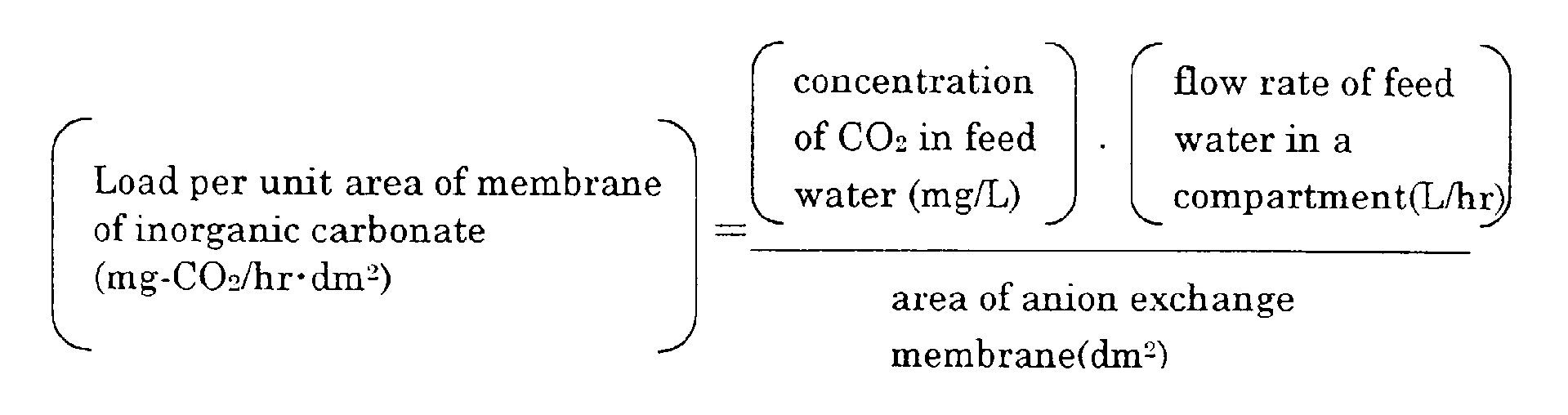
- The inventors of this invention conducted experiments for making clear the forming mechanism of scales in the electrodeionization apparatus. In the experiments, scales were intentionally formed by mixing excessive amounts of inorganic carbononate and Ca2+ in feed water to the electrodeionization apparatus. After that, the apparatus was disassembled and the concentrating compartment was observed. As a result, it was found that calcium carbonate adhered to the anion-exchange membrane at the concentrating compartment side.
- Accordingly, the inventors presumed that the forming mechanism of scales was follows. That is, when the electrodeionization apparatus is in operation, pH near a surface of the anion-exchange membrane locally become alkaline. CO3 2- or HCO3 - and OH- permeating the anion-exchange membrane from the diluting compartment are concentrated near the anion-exchange membrane. In addition, Ca2+ in water in the concentrating compartment is drawn or driven to the anion-exchange membrane, so that CO3 2- or HCO3 - and OH- react with Ca2+ to form scales of calcium carbonate on the anion-exchange membrane.
- The inventors further studied and found that no scale forms when the scale index SI obtained by multiplying the load per unit area of inorganic carbonate of the anion-exchange membrane by the Ca2+ concentration in concentrated water is 500 or less. The load of inorganic carbonate (mg-CO2/hr) of the electrodeionization apparatus is obtained by multiplying the inorganic carbonate concentration (mg-CO2/L) of water fed to the electrodeionization apparatus by the flow rate (L/hr). Therefore, the load of inorganic carbonate per unit area (mg-CO2/hr·dm2) is the product of [the inorganic carbonate concentration (mg-CO2/L) of feed water] and [the flow rate per cell(L/hr) / the effective area of cells of the anion exchange membrane (dm2)].
- By controlling the scale index SI to be 500 or less, preferably 200 or less, precipitation of scales of calcium carbonate can be securely prevented in the concentrating compartment of the electrodeionization apparatus, thus enabling the stable operation of the electrodeionization apparatus for a long period of time.
- In the electrodeionization apparatus, electric current more than the theoretical amount required to discharge ions from feed water is supplied to occur dissociation of water in the diluting compartments so as to continuously regenerate the ion exchanger. Therefore, increase in electric current to be supplied increases the alkalinity of the pH at the surfaces of anion-exchange membranes, facilitating the precipitation of calcium carbonate. Accordingly, the permissible SI varies according to the value of electric current.
- In the electrodeionization apparatus which is directed to produce water having resistivity of about 10 MΩ·cm, the SI not exceeding 200, preferably not exceeding 150, is enough, when the required removing rate of silica is less 90% or when the current efficiency during its operation exceeds 20%. In view of economic consideration, the SI is preferably in a range between 80 and 200 to avoid treatment by a degassing apparatus, a softener, and/or such other extra device.
- In case of electrodeionization apparatus in which the required removing rate of silica is 90% or more i.e. the current efficiency during its operation is 20% or less, the SI is preferably is 120 or less, particularly 80 or less. In view of economic consideration, the SI is preferably in a range between 50 and 120.
- In case of electrodeionization apparatus in which the concentrating compartments are filled with the ion exchanger, the OH- ions permeated the anion-exchange membrane are easy to move in the concentrating compartment, so that the scale is dispersed. In this case, the permissible SI is 80 or more even preferably 80-200 when the electric current is increased. The more preferable SI in this case is in a range between 80 and 150. If economic consideration is not taken, SI lower than 80 is also permissible.
- To lower the SI to the specific value, there are some methods as follows. One of the methods is to lower the Ca2+ concentration in the concentrated water by removing Ca2+ by lowering the recovery of water or by the use of a Ca2+ removing device such as a softener. Another method is to lower the load on the membrane surface of the inorganic carbonate by reducing the amount of the water to be treated in the electrodeionization apparatus or removing inorganic carbonate by the use of a degassing device disposed at upstream of the electrodeionization apparatus. Alternative method of lowering the load on membrane surface of inorganic carbonate is to control the electric current of the electrodeionization apparatus.
- As the electrodeionization apparatus of the present invention is operated with recovery of water 80% or more, the conductivity of water in the concentrating compartment should be high, thereby achieving excellent quality of treated water.
- Water to be treated having CO2 concentration of 10 ppm or less may be passed through a reverse osmosis apparatus before being introduced into the electrodeionization apparatus of the present invention.
- In the present invention, the conductivity of the water in the concentrating compartments is preferable to be equal to or more than 50 µS/cm. The interrelationship between the conductivity and the elecrical resistance of the concentrated water in the electrodeionization apparatus is shown in Fig.14. Fig.14 shows that the electrical resistance increases rapidly as the conductivity falls below 50 µS/cm. Therefore, the conductivity of at least 50 µS/cm is required at the outlet of the concentrating compartments to ensure the electrical current. When the conductivity is below 50 µS/cm, the electrical resistance would increase to raise the electric cost.
- Hereinafter, the apparatus for producing purified water of the present invention will be described in detail with reference to Fig.1 and Fig.2. Fig.1 and Fig.2 are invention respectivery according to and embodiment.
- The apparatus for producing purified water shown in Fig.1 is provided with a
RO apparatus 2, a first precedingelectrodeionization apparatus 3A and a second succeedingelectrodeionization apparatus 3B which are connected in series. The apparatus for producing purified water shown in Fig.2 is provided with an activatedcarbon apparatus 1,RO apparatus 2, the precedingelectrodeionization apparatus 3A, and the succeedingelectrodeionization apparatus 3B which are connected in series. - The preceding
electrodeionization apparatus 3A is related to the present invention mentioned above. - The succeeding
electrodeionization apparatus 3B is conventional electrodeionization apparatus. The thickness of the diluting compartments of the succeedingelectrodeionization apparatus 3B is preferable to be smaller than that of the precedingelectrodeionization apparatus 3A and to be in the range of 2.0 to 6.0mm. - Any one of the succeeding electrodeionization apparatus may be that of the present invention, so that the purified water producing apparatus becomes to have a high flow rate and the purified water producing apparatus becomes compact in its constitution.
- The electrodeionization apparatus of the present invention may have diluting compartments, each of which is divided into a plurality of cells by a partition member, and an ion exchanger is filled in the respective cells. At least a part of the partition member facing the cell is inclined relative to a normal flow direction of the water in the diluting compartment. The inclined part of the partition member allows permeation of the water, but prevents the ion exchanger to pass therethrough. Therefore, at least a part of the water flowing into the diluting compartment should flow obliquely relative to the normal flow direction of water, so that the water is dispersed overall the diluting compartment, thereby improving the contact efficiency between water and ion exchanger and improving the deionization property.
- The water flows in the cells with being stirred by the inclined part of the member, so that a boundary layer of concentration along the surface of the membrane whereby a dispersion resistance of ions is lowered and the apparatus becomes possible to be operated with a high flow velocity.
- In an aspect of the invention, the apparatus has a large number of cells are arranged vertically and laterally. A plurality of cells are arranged along the membrane surface both in the normal flow direction of water and a direction perpendicular to the normal flow direction, thereby extremely improving the contact efficiency between water and ion exchanger. Since the height of each cell is low, the ion exchanger is scarcely compressed. A vacancy is not formed at an upper portion in the cell, and the cell is filled evenly with the ion exchanger.
- The configuration of each cell seen by projecting it upon the surface of the membrane is preferably a hexagon or a quadrangle. In case of the hexagon, the cells are preferably arranged in such a manner that a pair of sides thereof extend in the normal flow direction of water. In case of quadrangle, the cells are preferably arranged in such a manner that the respective sides thereof extend obliquely relative to the normal flow direction of water.
- All of the cells may be filled with the same ion exchanger, or instead thereof some of the cells may be filled with ion exchanger different from the ion exchanger filled in the other cells. For example, an anion exchanger may be filled in first cells, a cation exchanger may be filled in second cells, and an amphoteric ion exchanger (or a mixture of the anion exchanger and the cation exchanger) may be filled in third cells.
- This electrodeionization apparatus may be installed at the succeeding stage of the purified water producing apparatus of the present invention, whereby monovalent cations such as Na+ leaked from the preceding stage are removed by the succeeding electrodeionization apparatus even when the feed water is fed at a high rate.
- Hereinafter, other embodiments of the present invention will be described with reference to the attached drawings. Fig. 9 is an exploded perspective view showing the structure of a diluting compartment according to another embodiment, and Fig. 10 is a front view illustrating the water flowing condition of the partition member.
- The diluting compartment comprises a
rectangular frame 120, apartition member 121, preferably having conductivity, disposed in theframe 120, anion exchanger 123 filled incells 122 formed by thepartition member 121, an anion-exchange membrane 124 and acation exchange membrane 125 which are disposed to sandwich theframe 120. Thepartition member 121 may be electrically-conductive. - The
frame 120 is provided with aflow inlet 126 for introducing raw water to be treated and aflow inlet 127 for concentrated water in an upper portion thereof and with aflow outlet 128 for deionized water and aflow outlet 129 for concentrated water formed in a lower portion thereof. Theflow inlet 126 and theflow outlet 128 are connected to the inside of theframe 120 through a notch-like channels - Though only one
channel 126a is illustrated to communicate with only the left top cell in Fig. 9, actually a plurality ofchannels 126a are formed in the upper portion of theframe 120 to uniformly distribute the raw water into the respective top cells aligned in the lateral direction, that is, thechannels 126a directly communicate with the respective top cells. In the same manner, though only onechannel 128a is illustrated to communicate with only the right bottom cell in Fig. 9, actually a plurality ofchannels 128a are formed in the lower portion of theframe 120 so as to directly communicate with the respective bottom cells. - The
partition member 121 according to this embodiment is in a honeycomb form of a hexagonal shape in which a large number of cells are arranged in vertical and lateral directions in such a manner that a pair of sides of eachcell 122 extend in the longitudinal direction of theframe 120, i.e. in the vertical direction. The vertical surfaces 131 may be permeable or not permeable to water. - When the vertical surfaces 131 are not permeable to water, uniform contact between water and the ion exchanger in the cells can be achieved so that the quality of product water is improved.
- The other structure of the electrodeionization apparatus having this diluting compartment is the same as that of the aforementioned conventional one of Fig. 12 and the flow passages for raw water, concentrated water, and electrode water are also the same as those of the conventional one.
- As shown in Fig. 12, a cathode compartment is formed and defined by the cathode, the cathode spacer, and the cation-exchange membrane.
- When the deionizing operation is conducted by passing raw water through this electrodeionization apparatus, the raw water introduced into the diluting compartment permeate the
partition member 121 surrounding thecells 122 so as to flow intoadjacent cells 122 and thus gradually flows downwardly. During this, the water is deionized. Finally, the water reaches the bottom of the diluting compartment and flows out to theflow outlet 128 through thechannels 128a. Through theflow outlet 128, the water is took out from the electrodeionization apparatus as the deionized water. - The general direction of water in the diluting compartment is a downward vertical direction because the
channels 126a for introducing raw water exist at the top of theframe 120 and thechannels 128a for taking out the deionized water exist at the bottom of theframe 120. Thepartition 121 is inclined relative to the general direction of water exist at upper portions and lower portions of the respective cells, so that the water flows obliquely and downwardly from onecell 122 into the lowerleft cell 122 and the lowerright cell 122. Therefore, the water flows substantially uniformly to allcells 122, thereby improving the contact efficiency between the water and the ion exchanger. - In this diluting compartment, since the
cells 122 are relatively small, the downward pressure applied to the ion exchanger in each cell by the self weight of the ion exchanger and water pressure is low. Therefore, the ion exchanger is not compressed in any of thecells 122, thereby preventing the ion exchanger from being partially compressed at the lower portion of the cells. - Employed as the ion exchanger to be filled in the
cells 122 may be an anion exchanger, a cation exchanger, an amphoteric ion exchanger, or a mixture of at least two of them. - Though the cells are hexagonal in Figs. 9 and 10, the cells may be quadrangular e.g. rhombic just like
cells 145 shown in Fig. 11. - In the electrodeionization apparatus of the present invention, the projected area to the ion exchange membrane of the cells is preferably 1-100 cm2, particularly 2-50 cm2, more particularly 3-10 cm2. As the size of the cells is reduced, the amount of the ion exchanger to be filled in one cell is reduced so that the fluidization of the ion exchanger is restrained. In addition, the strength of the partition member and the strength of the diluting compartment are increased. However, the pressure loss of the water flowing in the diluting compartment is increased.
- The ion exchanger to be filled is normally an ion exchange resin. But the ion exchanger may be an ion exchange fiber, ion exchange non-woven fabric, or a mixture of an ion exchange resin and an ion exchange fiber. Ion conductor such as conductive resin may be employed.
- When the thickness of the diluting compartments of preceding
electrodeionization apparatus 3A is equal to or more than 7mm, particularly in the range of 8 to 30mm, and the thickness of the diluting compartments of the succeedingelectrodeionization apparatus 3B is in the range of 2.0 to 6.0mm, the precedingelectrodeionization apparatus 3A removes the weakly - ionized species including silica, boron, and the hardness, and the succeedingelectrodeionization apparatus 3B further removes silica and boron. The succeedingelectrodeionization apparatus 3B removes the alkalis leaked from the precedingelectrodeionization apparatus 3A, the product water becomes high quality. - The water to be fed into the preceding electrodeionization apparatus is preferable to contain Na+ of equal to or more than 0.1ppm as Na+. When the water is poor in Na+, the water is preferably added with NaCl.
- To raise pH of the product water flown out of the preceding
electrodeionization apparatus 3A, the feed water needs to contain Na+ ion. The relationship between the concentration of Na+ in the feed water and pH of the product water is shown in Fig.15. As shown in Fig.15, the concentration of Na+ is required to be equal to or more than 0.1 ppm as Na+, preferably in the range of 0.5 to 4 ppm as Na+. - The concentration of CO2 in the water to be fed into the preceding electrodeionization apparatus is preferable to be equal to or less than 3ppm as CO2.
- When the raw water contains a large amount of CO2 which dissociates under alkaline condition, the removing rates of silica and boron decrease. When the concentration of CO2 exceeds 3ppm, it is preferable to remove CO2 by the use of a degassing apparatus installed in the upstream or by increasing pH of the water fed into the RO apparatus to 8 or more to form HCO3-.
- The water recovery rate of preceding
electrodeionization apparatus 3A is preferable to be 60 to 90%. Even when the water recovery rate of succeedingelectrodeionization apparatus 3B is equal to or more than 95%, for example the rate is in the range of 95 to 99%, the product water of good quality is produced without causing scale. - As the electrical voltage and current applied to the preceding
electrodeionization apparatus 3A are increased, pH of the water treated in the preceding electrodeionization apparatus becomes high. Therefore, it is preferable to observe pH by installing apH meter 4 to the pipe for discharging the treated water from precedingelectrodeionization apparatus 3A and to control the voltage and the current applied to the precedingelectrodeionization apparatus 3A so that the value of pH becomes preferably equal to or more than 8.5, more preferably between 9.0 and 10.5. The precedingelectrodeionization apparatus 3A is preferable to remove Na+ at a rate of less than 90% and the chloride ion of more than 95%. When the chloride removing rate is more than 95%, pH becomes high. - It is preferable that a
resistivity meter 5 and asilica meter 6 are installed to the pipe for discharging the product water from the succeedingelectrodeionization apparatus 3B in order to observe the resistivity and the concentration of silica of the water product in the succeedingelectrodeionization apparatus 3B, and the voltage and the current applied to theapparatus 3A and /or theapparatus 3B are controlled so that the resistivity and the concentration of the silica are in the sights. - When the
electrodeionization apparatuses - The "A", "Q", and "SV" are as follows:
- A: the operational current (A);
- Q: the flow rate of the feed water per cell in the diluting compartments (L/sec), where "L" is liter; and
- SV: the flow rate of the feed water per ion exchangers in the diluting compartments (L/L - ion exchangers·sec).
-
- The removal rate of silica is closely related to the value of A/(Q · SV). A/(Q · SV) of 4000 or more can achieve the silica removing rate of 97% or more.
- The apparatus for producing purified water of the present invention may by provided with a RO apparatus, a degassing apparatus where the permeating water passing thorough the RO apparatus is introduced, and the electrodeionization apparatus where the water treated in the degassing apparatus is introduced. It is preferable that the feed water having M - alkalinity expressed as CaCO3 of more than 20 ppm and pH of or more than 6.5 is fed to the RO apparatus, and that the water having pH of less than 6.2 is taken out from the RO apparatus and fed into the degassing apparatus.
- It is preferable that the degassing apparatus is a membrane degassing apparatus and the water to be introduced to the degassing apparatus has TOC of less than 200ppb or conductivity of less than 20 µS/cm.
- The M - alkalinity is the feed water is removed by the RO apparatus, so that the permeating water thereof has low pH. The water having low pH is efficiently removed in CO2 by the degassing apparatus, so that the electrodeionization apparatus can be reduced in the load of CO2. loaded thereon.
- The ability to remove CO2 can be improved by 30 to 50% by degassing the water which is decreased in pH by treating with the RO apparatus in comparison with the case where the water is degassed before the treatment with the RO apparatus.
- Particularly when the membrane degassing apparatus is employed for the degassing apparatus, the degassing apparatus arranged behind the RO apparatus can stabilize the ability to degas for a long period of time.
- This is because the RO apparatus removes salts and TOC (total organic carbon), so that a slime defects caused by the salts and the TOC are avoided. It is preferable that the feed water into the membrane degassing apparatus has the TOC concentration of less than 200ppb, and/or the electric conductivity of 20 µS/cm in order to prevent the membrane from contamination and to stabilize the degassing ability for a long period.
- The reject water of the
RO apparatus 2 is discharged as the drain and the permeated water of theRO apparatus 2 is distributed and fed into the electrodic compartment 3Aa, the diluting compartments 3Ab and concentrating compartments 3Ac of the precedingelectrodeionization apparatus 3A respectively. The product water of the precedingelectrodeionization apparatus 3A (the water flowing out from the diluting compartments 3Ab) is distributed and fed into the electrodic compartment 3Ba, the diluting compartments 3Bb and the concentrating compartments 3Bc of the succeedingelectrodeionization apparatus 3B respectively. The water flowing out from the diluting compartments 3Bb is discharged as the product water. The water flowing out from the electrodic compartments 3Aa and 3Ba is discharged as the drain. - The concentrated water flowing out from the concentrating compartments 3Ac of the preceding
electrodeionization apparatus 3A is acidic, and the concentrated water flowing out from the concentrating compartments 3Bc of the succeedingelectrodeionization apparatus 3B is alkaline. Therefore, it is preferable that the concentrated water flowing out from the concentrating compartments 3Ac and 3Bc are mixed and returned to the inlet portion of theRO apparatus 2. - The concentrated water of either preceding
electrodeionization apparatus 3A or succeedingelectrodeionization apparatus 3B may be independently fed back to the front stage of theRO apparatus 2. The concentrated water of the succeedingelectrodeionization apparatus 3B may be fed back to the inlet portion of the precedingelectrodeionization apparatus 3A. - While the electrodeionization apparatus shown in Fig.1 and Fig.2 has one
electrodeionization apparatus 3B, the electrodeionization apparatus may be provided with two ormore electrodeionization apparatuses 3B which are connected in series. - As shown in Fig.7 and Fig.8,
cells 23 of more than 7mm in the thickness of diluting compartments andcells 24 of less than 7mm in the thickness of the diluting compartments may be arranged between an anode 21 (or 21A, 21B) and acathode 22 so that the fed water flows through these cells in series. - The electrodeionization apparatus of the present invention is preferably operated so that the concentration of silica of the concentrated water flowing out from the concentrating compartments of the second or later electrodeionization apparatus is less than one thousand times as high as that of the produced water of the electrodeionization apparatus. In order to lower the concentration of silica of the produced water to 0.1 ppb or less, the concentration of silica of the concentrated water is preferable to be decreased to 100ppb or less.
- When the electrodeionization apparatus is operated in this manner, since the concentration gradient of silica from the concentrating compartments to the diluting compartments is relatively low even in the vicinity of the outlet of the concentrating compartments, the diffusion of silica from the concentrating compartments to the diluting compartments is retarded so that the concentration of silica of the produced water is reduced.
- In the present invention, the apparatus for producing purified water may be composed of a RO apparatus, a first electrodeionization apparatus and a second electrodeionization apparatus so that the water firstly flows from a reverse osmosis membrane apparatus into the first apparatus and then flows into the second electrodeionization apparatus wherein the reverse osmosis membrane apparatus consists of the reverse osmosis membrane having the degree of desalination of monovalent salts of equal to or less than 97%.
- Hereinafter, "the degree of desalination of monovalent salts" will be simply called as "the degree of the desalination".
- As shown in Fig.14 mentioned above, the electrical resistance rapidly increases as the conductivity of the concentrated water of the electrodeionization apparatus falls below 50 µS/cm. The conductivity of more than 50 µS/cm, preferably more than 75 µS/cm reduces the electrical resistance and sufficiently ensures the electrical current required for deionization in the electrodeionization apparatus.
- When usual tap water or industrial water having the conductivity of about 200 µS/cm is fed into the RO apparatus installed with the RO membrane having the degree of desalination of 97%, and the water is treated under water recovery of 75 %, the conductivity of the water permeated through the RO membrane is defined as follows.
- When the electrodeionization apparatus is operated at the water recovery of 80 % by feeding the above water permeated through the RO membrane, the conductivity of the cocentrated water is 15×5=75µS/cm.
- While the conductivity of the concentrated water varies depending on the conductivity of the raw water to be fed into the RO apparatus, the water recovery of the electrodeionization apparatus, by employing the RO membrane having the degree of desalination of equal to or less than 97%, the concentrated water can be provided with the conductivity of roughly 75 µS/cm or more in operation employing the usual raw water and the usual water recovery and the electricalent can be ensured in the electrodeionization apparatus.
- In the present invention, it is very important to feed the permeating water obtained by treating the feed water by RO membrane having realtively low degree of desalination into the diluting compartments since the conductivity of the concentrated water can not be ensured when the permeating water is fed into the concentrating compartments alone, and the results prevent decrease of the electrical resistance and improvement of the electrical current.
- Furthermore, the RO membrane preferably has the removal rate of the hardness and silica of equal to or more than 97%. That is, the hardness such as by Ca2+ and silica easily form scales in the electrodeionization apparatus and require the appreciably electrical current to remove the scales. Therefore, the hardness and silica are preferably removed in the RO apparatus preceding the electrodeionization apparatus, so that the RO membrane having the removal rate of the hardness and silica of more than 97% is preferable to be employed.
- The RO membrane mentioned above may be commercially saled one. It may be prepared by being treated with oxidizer so that the RO membrane becomes hydrophilic and has the degree of desalination of equal to or less than 97% and the removal rate of silica of equal to or more than 97%.
- In the present invention, the electrodeionization apparatus is preferably provided with the diluting compartments having a thickness of equal to or more than 7mm.
- That is, when the permeate water of the RO apparatus in which NaCl and the like remains is fed into the electrodeionization apparatus wherein the diluting compartments having a large thickness as above is employed and wherein the ion exchange layer comprising the anion exchanger alone or mixture of the anion exchanger and the cation exchanger is filled in the diluting compartments, the conductivity of the product water (deionized water) is almost same as of the fed water or slightly larger than it, while carbon dioxide gas (CO2) and anions are removed and about 90% of silica and boron are also removed. Besides, the hardness including Ca2+, Mg2+ is further removed. However, since the monovalent cations including Na+, K+ are inferior in the removal rate so that the alkalis including NaOH and KOH which have large molar conductivity are to be leaked into the product water, and the product water tends to be increased in pH and slightly in conductivity.
- For the same reason as above, since OH- is difficult to be discharged and H+ is easy to be discharged in the concentrating cells, pH becomes acidic therein so that the scale is not formed even when Ca2+, Mg2+ and the like are concentrated at high concentration.
- Specifically, in order to decrease the electrical resistant and to increase the electrical current of the electrodeionization apparatus , the electrodeionization apparatus is increased in the conductivity of the concentrated water by employing the RO membrane having the degree of desalination of monovalent salts represented by NaCl of equal to or less than 97 % to leak the monovalent salts into the RO permeating water so that the permeated water is fed into the diluting compartments of the electrodeionization apparatus. When the degree of desalination of RO membrane exceeds 97%, the aforementioned effect is not sufficiently achieved.
- While the degree of desalination of the RO membrane is preferable to be low for the purpose of increasing the conductivity of the concentrated water of the electrodeionization apparatus so as to decrease the electrical resistance and to improve the electrical current of the electrodeionization apparatus, when the degree of desalination is unduly decreased, the decrease of the current is small and, rather, the load on the electrodeionization apparatus increases because of degradation of the quality of the feed water so that the product water (deionized water) is degraded in its quality. Therefore, RO membrane is preferably to have the degree of desalination especially of 90 to 95 %.
- The RO membrane as the above may employ a membrane being marketed as low desalination membrane, for example a membrane called as a loose RO membrane and a nano - filtration (NF membrane) membrane, specifically, "LES 90" and "NTR-729HF" produced by Nitto Electrical Industry Co., Ltd.
- In the present invention, the RO membrane is also preferably to have the removal rate of the hardness and silica, more preferably besides the removal and silica, more preferably besides the removal rate of TOC (total organic carbon) of equal to or more than 97 %.
- In the preceding electrodeionization apparatus of the purified water producing apparatus of the present invention, by the same reason as above, the electrodeionization apparatus is preferable to be provided with the diluting compartments having a thickness of equal to or more than 7mm, particularly of 8 to 30mm.
- The ion exchanger is most preferable to be a mixture of the anion exchanger and the cation exchanger. When the applied current is increased, a single layer comprising the anion exchanger alone can being the same effect as the mixture. Of course, a combination of the mixture and the anion exchanger may be employed.
- In the present invention, an ultraviolet - light irradiating apparatus may be installed between electrodeionization apparatuses to decompose TOC in the water.
- When the product water of the preceding electrodeionization apparatus is alkaline, the ultraviolet - light irradiating apparatus decompose TOC at high efficiency. When hydrogen peroxide or ozone having concentration of 2 to 20 times as high as the concentration of TOC in the water is added into the product water, the efficiency of decomposition is further increased.
- In the present invention, a first RO apparatus may be installed before the preceding electrodeionization apparatus, and a second RO apparatus may be installed between the preceding electrodeionization apparatus and the succeeding electrodeionization apparatus.
- By using the RO apparatus, silica and boron are easily removed from the alkaline feed water. Since the product water flowing out from the preceding electrodeionization apparatus is alkaline without adding alkalis including NaOH, the second RO apparatus easily removes silica and boron from the product water.
- For example, in the apparatus comprising the first RO apparatus, the preceding electrodeionization apparatus, the second RO apparatus and the succeeding electrodeionization apparatus which are arranged in this order and connected in series, when the water flowing into the second RO apparatus has pH of 7, the second RO apparatus removes 99% of silica and 70% of boron in the water. When the water flowing into the second RO apparatus has pH of 9, the second RO apparatus removes 99.9% of silica and 97% of boron.
- In the apparatus comprising the preceding electrodeionization apparatus and the succeeding electrodeionization apparatus which are connected in series, when water containing silica in a high concentration is fed into the apparatus momentarily, silica accumulates and the removal rate of silica may decrease even after the silica content of the feed water decreases down to usual. Therefore, the feed water fed into the preceding electrodeionization apparatus may be regularly added with salts including NaCl so that silica accumulated in the electrodeionization apparatus can is discharged therefrom.
- By adding the salts as above, at least one of the following requirements (i), (ii), and (iii) is preferable to be achieved for 5 to 48 hours:
- (i) To set the conductivity of the feed water flowing into preceding electrodeionization apparatus for more than 15 µS/cm;
- (ii) To set the concentration of Na+ ion of the water flowing into the preceding electrodeionization apparatus for more than 3ppm; and
- (iii) To set pH of the product water flowing out preceding electrodeionization apparatus for more than 9.8
-
- Fig.15 shows an example of the interrelationship between pH values of the feed water fed into the preceding electrodeionization apparatus and the product water flowing out from the therefrom.
- It is further effective heat the feed water fed into the electrodeionization apparatus to more than 35°C besides to add the salts including NaCl to the feed water.
- It the conventional electrodeionization apparatus, slime is frequently formed whereby the differencial pressure of the concentrating compartments rises to prevent the operation. In the two - stages electrodeionization apparatus of the present invention, the concentrated water of the preceding electrodeionization apparatus becomes acidic and the concentrated water of the succeeding electrodeionization apparatus becomes basic without adding agents so that the slime is not be formed in the concentrating compartments. Even after six months operation, when the feed water including 10,000 of living bacteria per milli liter is fed into the preceding electrodeionization apparatus, the concentrated water of the preceding electrodeionization apparatus is decreased in number of the living bacteria to 100 per milliliter and the concentrated water of the succeeding electrodeionization apparatus is decreased in number of the living bacteria to 0 per milliliter.
- To raise the removal rate of silica, the alkaline chemicals may be added into the water between the first and second stages or the inlet of the first stage. Even when pH of the water is not sufficiently increased at the first stage, the treatment with the second or later electrodeionization apparatus improves the removal rate of silica.
- The feed water fed into the first electrodeionization apparatus is preferable to have pH of equal to or more than 9.5 in order to efficiently remove the weakly - ionized species including silica and boron by the second or later electrodeionization apparatus. Although the removal rate of silica is 99% when the feed water fed into the secondary electrodeionization apparatus has pH of 9.0, the removal rate of silica is 99.9% when the feed water fed into the secondary electrodeionization apparatus has pH of 9.5.
- In the second or later electrodeionization apparatus, the Ca2+ concentration in the feed water is preferable to be equal to or less than 30ppb, more preferable to be equal to or less than 5ppb as Ca2+ since the water flowing in the concentrating compartments and the electrodic compartment is alkaline. In the second or later electrodeionization apparatus, the basic feed water causes the scale of CaCO3 in the concentrating compartments and the electrodic compartment. Therefore, Ca2+ is required to be removed at the first stage.
- The following shows the apparatuses used in Examples and Comparative Examples. In Examples 1 to 5 and Comparative Examples 1 to 3, the apparatuses are arranged as shown in Fig.4 to be connected in series. In Example 6, the apparatus including two electrodeionization apparatuses are arranged as shown in Fig. 2 to be connected in series.
- 1) Activated carbon apparatus
: "Kuricoal KW 10-30" produced by Kurita Water Industries Ltd. - 2) RO apparatus
: "Maku-Ace KN 200" produced by Kurita Water Industries Ltd. - 3) Electrodeionization apparatus "Pure-Ace PA-200"
produced by Kurita Water Industries Ltd.
flow rate of product ; 100 liters per hour -
- An electrodeionization apparatus is assembled as shown in Fig.3 in which the following ion exchange membranes are employed and the diluting compartments are filled with mixture of 6 parts by volume of the following anion exchange resin and 4 parts by volume of the following cation exchange resin.
- The anion exchange resin and the cation exchange resin are sufficiently washed by ultra pure water before being filled in the diluting compartments. Each of the diluting compartments has a thickness of 2.5 mm and consists of 12 cells.
- The water is fed into the electrodeionization apparatus under conditions as shown in Table 1. The resistivity of the product water, the concentration and the removal rate of silica, boron and the other ions are measured and results are shown in Table 1.
- Anion exchange membrane : "Neosepta AHA" produced by Tokuyama Co,. Ltd
- Cation exchange membrane : "Neosepta CMB" produced by Tokuyama Co,. Ltd.
- : Anion exchange membrane "SA 10A" produced by Mitsubishi Chemical Corporation.
- : Anion exchange membrane "SK 1B" produced by Mitsubishi Chemical Corporation.
- An electrodeionization apparatus is assembled to conduct the treatment in the same manner as comparative example 1 except that each of the diluting compartments has thickness of 10 mm and consists of three cells, and the water is fed under conditions as shown in Table 1. The resistivity of the product water, the concentrated and the removal rate of silica, boron and the other ions are shown Table 1.
- Further, the variation in pH with the applied voltage is shown in Fig.5.
- The CO2 concentration of the feed water and the CO2 concentration of the water treated by the preceding
electrodeionization apparatus 3A are measured to calculate the removal rate. When the CO2 concentration of the feed water is lppm, the removal rate is 90%, and when the CO2 concentration of the feed water is 4ppm, the removal rate is 60% or less. - In Example 1, by employing the heterogeneous membrane for the ion exchange membrane, the removing rate of Na+ decreases from 46% to 40% and pH increases from 9.5 to 9.65.
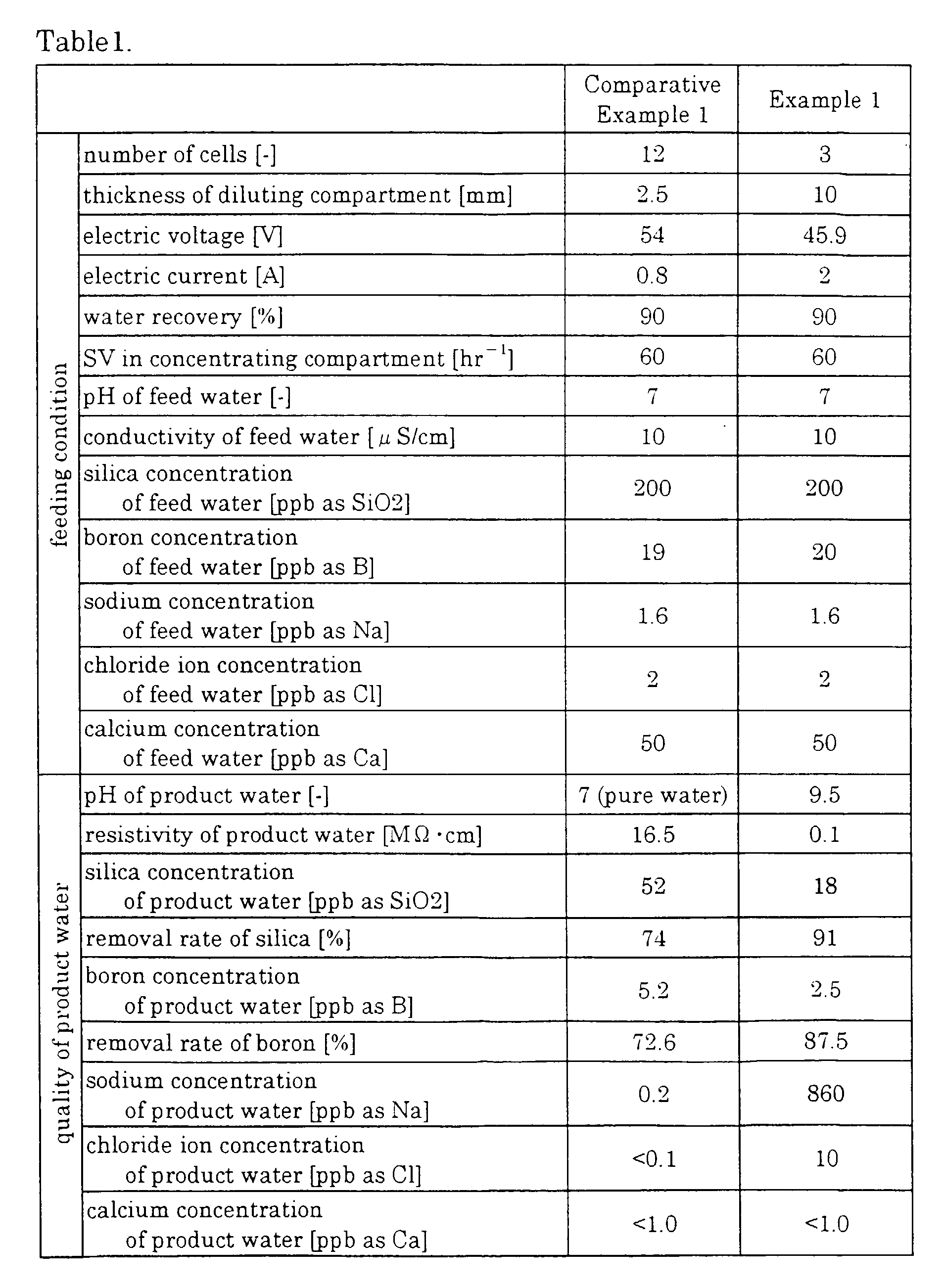
- Electrodeionization apparatuses are assembled in the same manner as Comparative Example 1 except that the diluting compartments of those respectively have thickness as follows. The water is treated under the same conditions as Comparative Example 1 except that the water is fed at SV of 60 per hour, and the electric voltage as the current efficiency falls in the range of 10 to 20%. The resistivity and pH of the product water are shown in Fig.6.
- Comparative Example 2 : 2.5mm
- Comparative Example 3 : 5.0 mm
- Example 2 : 7.0 mm
- Example 3 : 10.0 mm
- Example 4 : 15 mm
- Example 5 : 30 mm
-
- As shown in Fig.2, the activated
carbon apparatus 1, theRO apparatus 2 and theelectrodeionization apparatus electrodeionization apparatus 3A is the same electrodeionization apparatus provided with the diluting compartments having a thickness of 10mm as Example 1 and the succeedingelectrodeionization apparatus 3B is the same electrodeionization apparatus provided with the diluting compartments having thickness of 2.5mm as Comparative Example 1. Then, the feed water is fed into the apparatus under conditions as shown in Table2. The quality of the product water (flowing out from theelectrodeionization apparatuses 
- The results show the followings:
- As shown in Table 1, the electrodeionization apparatus of Example 1 provided with the diluting compartments having a thickness of 10mm slightly exceeds the electrodeionization apparatus of Comparative Example 1 provided with the diluting compartments having a thickness of 2.5mm in the removal rate of silica and boron. Calcium is almost entirely removed. As shown in Fig. 5, in the electrodeionization apparatus provided with the diluting compartments having a thickness of 10mm, pH of the product water increases as the applied voltage increases.
- As shown in Fig.6, as the thickness of the diluting compartments exceeds 7mm, the resistivity of the product water deteriorates to raise pH of the product water.
- In the preceding
electrodeionization apparatus 3A, the cells are applied with the voltage at 8V per cell, and in the succeedingelectrodeionization apparatus 3B the cells are applied with the voltage at 3V per cell. When the conventional electrodeionization apparatuses are employed, the cells of the preceding electrodeionization apparatus are applied with the voltage of 15V and those of the succeeding electrodeionization apparatus are applied with the voltage of 4.5V. - Table 2 shows that when the water is firstly treated in the electrodeionization apparatus provided with the diluting compartments having a thickness of 10mm and then fed into the electrodeionization apparatus provided with the diluting compartments having a thickness of 2.5mm, the concentration of silica and boron is lowered to the limit of analytic detection, and the product water of very good quality (
pH 7 and the resistivity of 18.2 MΩ · cm) can be contained. - The purified water producing apparatus shown in Fig.13 is assembled. The succeeding electrodeionization apparatus relates to the present invention which is provided with the cells having honeycomb structure in the diluting compartments. The product water flown out of the preceding electrodeionization apparatus is of the following quality:
- pH : 9.5
- conductivity : 13 µS/cm
- concentration of silica : 18 ppb
- concentration of boron : 2.5 ppb
-
- For comparison, the succeeding electrodeionization apparatus is substituted for the conventional electrodeionization apparatus provided with ribs in the diluting compartments.
- Operational conditions and results are shown in Table 3.
- The measuring conditions are as follows
- The cells of the electrodeionization apparatus : Hexagonal form, the area of which is 3.9 cm2.
- Spacing between ribs : 28mm
- Ion exchange resin of the diluting compartments : SA 10A of anion resin and SK 1B of cation resin; both of which are produced by Mitsubishi Chemical Corporation; (including 6 parts of the anion exchange resin and 4 parts of the cation exchange resin)
- Ion exchange membrane : AHA (anion exchange membrane), CMB (cation exchange membrane) produced by Tokuyama Co., Ltd.
- The operating conditions are shown in Table 3.
Example 7 (For comparison) number of cells 4 12 thickness of diluting compartment (mm) 5.0 2.5 height of cell (cm) 400 600 Space velocity (hr-1) 120 60 voltage applied (V) 25 54 current flown (A) 2.5 1.0 resistivity of product water (MΩ · cm) 18.2 18.2 SiO2 concentration in product water flown out of succeeding electrodeionization apparatus (ppb as SiO2) <0.1 <0.1 B concentration in product water flown out of succeeding electrodeionization apparatus (ppb as B) < 0.05 < 0.05 - As clearly shown by Table.3, the apparatus of the present invention provides the product water of high quality at a higher rate than the comparison one. It is also shown that apparatus of the present invention has the small height and is very compact.
- In Example 8 and Comparative Example 4, the apparatus for producing purified water in which the following activated carbon apparatus, RO membrane apparatus, and two electrodeionization apparatus are connected in series are used.
- Activated carbon apparatus : "Kuricoal KW10-30" produced by Kurita Water Industries Ltd.
- RO membrane apparatus : "Maku-Ace KN200" produced by Kurita Water Industries Ltd.
- Electrodeionization apparatus : "Pure-Ace PA-200" produced by Kurita Water Industries Ltd.
flow rate of product : 100 liters per hour - The electrodeionization apparatuses are assembled as shown Fig.1 wherein the following ion exchange membranes are employed in the aforementioned electrodeionization apparatus, the diluting compartments are filled with the mixture of the ion exchange resins composed of 6 parts by volume of the following anion exchange resin and 4 parts by volume of the following cation exchange resin. The anion exchange resin and cation exchange resin are sufficiently washed by the ultra - pure water before they are filled into the diluting compartments.
- Two types of electrodeionization apparatuses one of which is an electrodeionization apparatus "B" provided with the diluting compartments having a thickness W of 2.5 mm and consisting of 12 cells, and the other of which is an electrodeionization apparatus "A" provided with the diluting compartments having a thickness W of 10 mm and consisting of 3 cells are assembled.
- Anion exchange membrane : "Neosepta AHA" produced by Tokuyama Co., Ltd.
- Cation exchange membrane : "Neosepta CMB" produced by Tokuyama Co., Ltd.
- Anion exchange resin : "SA 10A" produced by Mitsubishi Chemical Corporation.
- Cation electrodeionization apparatus : "SK 1B" produced by Mitsubishi Chemical Corporation.
- The RO apparatus employs the RO membrane shown in Table 4 and the electrodeionization apparatus composed of the electrodeionization apparatus "A" and electrodeionization apparatus "B" which are connected together in series. The treatment is conducted under conditions where the flow rate of product is 100 liters per hour, the water flows in the electrodeionization apparatus at SV of 70 per hour, the recovery of the water in the RO apparatus is 75%, and the recovery of water in the electrodeionization apparatus 80%. The measurement of the water quality in the RO apparatus , and the voltage, the current and the water quality in the electrodeionization apparatus are shown in Table 4.
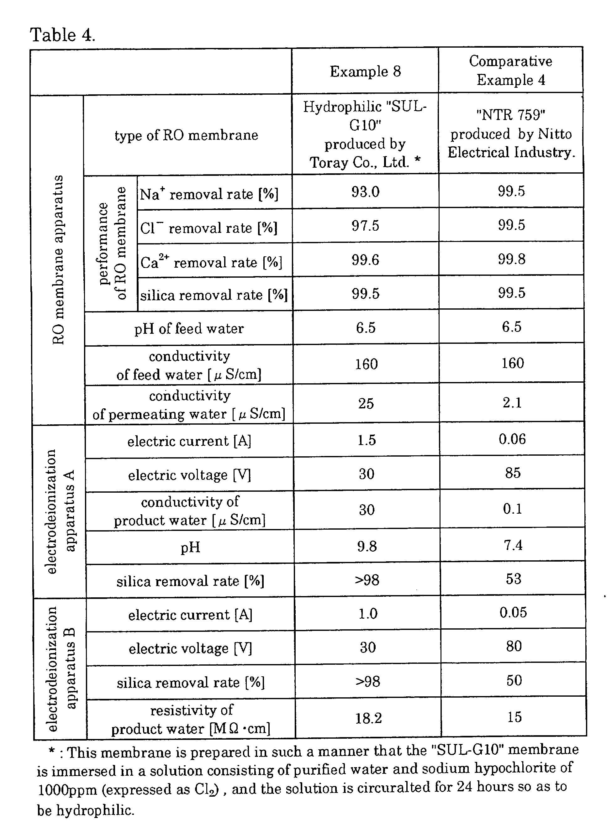
- According to Table 4, in Comparative Example 4 wherein the RO membrane having high degree of diluting is employed, the current hardly flows and the quality of the product water is scarcely improved in the electrodeionization apparatus. In contrast, in Example 8, the apparatus employing the RO membrane having the degree of diluting of equal to or less than 97%, preferably further having the removal rate of the hardness and the silica of equal to or more than 97%, and employing the diluting compartments having a thickness of equal to or more than 7mm to achieves high quality of the product water by large current and diluting efficiency.
- The electrodeionization apparatus of Example 1 shown in Table 1, and ultraviolet-light irradiating apparatus provided with two UV lumps ("AZ-26 (0.1 kW)" produced by Japan Photo Science Co,. Ltd.), and the succeeding
electrodeionization apparatus 3B shown in Table 2 are arranged in this order and connected in series. Raw water having TOC of 300ppb is fed into the apparatuses. The product water flowing out of the preceding electrodeionization apparatus has pH of 9.5. - The measurements of TOC concentration of the product water flowing out of each electrodeionization apparatus are shown in Table 5.
Example 9 Example 10 Comparative Example 5 TOC of product water of preceding electrodeionization apparatus [ppb] 55 55 70 TOC of product water of succeeding electrodeionization apparatus [ppb] 2.5 1.1 10 TOC of raw water : 300ppb - In Example 9, H2O2 is added to the product water flowing out from the preceding electrodeionization apparatus to set the concentration in the water for lppm. The measurements of TOC are shown in Table 5.
- Treatment is made in the same manner as Example 9 except that the electrodeionization apparatus of Comparative Example 1 shown in Table 1 is employed for preceding electrodeionization apparatus and NaCl added to the product water flowing out from the preceding electrodeionization apparatus to measure the TOC. The measurements of TOC are also shown in Table 4.
- In this treatment, NaCl is added in order to increase the conductivity to about 15 µS/cm. In Examples 9 and 10, the conductivity of the feed water flowing out from the preceding electrodeionization apparatus is about 15 µS/cm.
- As shown Table 5, according to the present invention, the concentration of TOC is sufficiently lowered.
- The apparatus of Example 6 is inspected about influence of foul by silica, and a method of recovery thereof is searched.
- When raw water having concentration of silica of 10,000ppb is continuously fed into the apparatus of Example 6 for 24 hours, the concentration of silica of the product water flowing out from the preceding electrodeionization apparatus becomes 150ppb, and that of the product water flowing out from the succeeding electrodeionization apparatus becomes 15ppb.
- Then, feed water is changed to contain silica at a concentration of 200ppb, and NaCl is added to the feed water to be fed into the preceding electrodeionization apparatus for 24 hours so as to set the conductivity of the feed water for 25 to 30 µS, pH of the water flowing out from the preceding electrodeionization apparatus for 10 to 10.2, the electrical voltage applied to the preceding electrodeionization apparatus for 35.2V, the current applied to the preceding electrodeionization apparatus for 2A, the electrical voltage applied to the succeeding electrodeionization apparatus for 41V, and the current applied to the succeeding electrodeionization apparatus for 1A. 3days after, the concentration of silica of the product water flowing out from the preceding electrodeionization apparatus becomes 25ppb, and that of the product water flowing out from the succeeding electrodeionization apparatus becomes 0.2ppb.
- The same experiment as Example 11 is conducted except that in the
above step 2, NaCl is not added. As the result thereof, the silica concentration of the product water flowing out from the succeeding electrodeionization apparatus becomes 2.5 ppb which is extremely higher than in Example 6. - Table 6 shows the results of Example 11 and Comparative Example 6.
at a normal state under fouled conditon (24hours) normal state(3days after) Comparative Example 6 Example 11 Example 12 Concentration of silica in feed water 200 10,000 200 200 200 Concentration of silica in product water flown out of the preceding electrodeionization apparatus [ppb] 18 150 50 25 15 Concentration of silica in product water flown out of the succeecing electrodeionization apparatus [ppb] <0.1 15 2.5 0.2 < 0.1 - In Example 11, the feed water fed into the preceding electrodeionization apparatus is heated to 40°C besides addition of salt to the feed water . As the result, the silica concentration of the product water flowing out from the preceding electrodeionization apparatus is lowered to 15ppb and that of the product water flowing out from the succeeding electrodeionization apparatus is lowered to less than 0.1ppb.
- As described above, according to the diluting compartments of the present invention, the weakly - ionized species having high disocciation constant such as silica and boron are efficiently removed without need of adding alkaline agent and without formation scale.
- According to the apparatus for producing purified water of the present invention, by employing the multi - staged electrodeionization apparatuses the first of which relates to the present invention, the pure water of high purity is easily and efficiently produced, and the apparatus for producing purified water is provided at low cost.
Claims (19)
- An electrodeionization apparatus comprising:wherein a thickness of the diluting compartments, operational electric voltage and/or current, and space velocity (SV) of flow are designed so that product water having pH higher than pH of feed water by 1.0 or more is obtained when the feed water having pH of equal to or less than 8.5 is treated without adding an alkaline agent.a cathode;an anode;concentrating compartments and diluting compartments alternately formed by arranging a plurality of cation exchangers and anion exchangers between the cathode and the anode; and,ion exchangers filled in the diluting compartments,
- An electrodeionization apparatus claimed in claim 1, wherein the diluting compartment has a thickness of equal to or more than 7mm, the operational voltage is 1 to 50V par cell, and the space velocity is 30 to 150 per hour.
- An electrodeionization apparatus claimed in claim 1 or 2, wherein the ion exchanger is a mixture of an anion exchanger and a cation exchanger or the anion exchanger alone.
- An electrodeionization apparatus as claimed in any one of claims 1 through 3, wherein hardness in the feed water can be removed by more than 50%.
- An electrodeionization apparatus as claimed in any one of claims 1 through 4, wherein the feed water includes silica and/or boron.
- An electrodeionization apparatus as claimed in any one of claims 1 through 4, wherein the rate (RA/RC) of electric resistance (RA) of the anion exchange membrane and the electric resistance (RC) of the cation exchange membrane is equal to or less than 0.8.
- An electrodeionization apparatus claimed in any one of claims 1 through 6, wherein the whole space between the cathode and the cation membrane of the diluting compartments that is nearest to the cathode is designed for cathodic compartment,wherein a cation exchange membrane is arranged between the anode and the anion exchange membrane of the diluting compartments that is nearest to the anode,wherein a concentrating compartments is designed between said cation exchange membrane and said diluting compartments that is nearest to the anode, andwherein an anodic compartment is designed between said cation exchange membrane and the anode.
- An electrodeionization apparatus claimed in any one of claims 1 through 7, wherein the foremost electrodeionization apparatus is provided with the anion exchange membrane having an homogeneous thickness and the cation exchange membrane having an heterogeneous thickness.
- An apparatus for producing purified water consists of two or more electrodeionization apparatuses connected so that water to be treated flows down therethrough,
wherein the foremost electrodeionization apparatus is an electrodeionization apparatus claimed any one of claims 1 through 8. - An apparatus for producing pure water claimed in claim 9, wherein a diluting compartment of the second or later electrodeionization apparatus is thinner than the diluting compartments of the foremost electrodeionization apparatus.
- An electrodeionization apparatus as claimed in claim 9 or 10, wherein said diluting compartments is divided into cells by a partition member,wherein at least a part of the partition member facing the cell is inclined relative to a normal flow direction of the water in the diluting compartment, andwherein at least inclined part of the partition member allows the water to pass, but prevents the ion exchanger to pass therethrough.
- An apparatus for producing purified water claimed in any one of claims 9 through 11, wherein a pipe connecting the foremost electrodeionization apparatus and the second electrodeionization apparatus is provided with a pH meter,
wherein the operation of the foremost electrodeionization apparatus is controlled so that the measurement of pH measured by said pH meter is equal to or more than 8.5. - An apparatus for producing purified water claimed in any one of claims 9 through 12, wherein a pipe for discharging product water from the succeeding electrodeionization apparatus is provided with a meter for measuring the resistivity and/or the concentration of silica, and the electrodeionization apparatuses are controlled based on measurements of the meter.
- An apparatus for producing purified water claimed in any one of claims 9 through 13, wherein a water recovery of the succeeding electrodeionization apparatus is equal to or more than 95%.
- An apparatus for producing purified water claimed in any one of claims 9 through 14, wherein an ultraviolet-light irradiating apparatus is installed between the electrodeionization apparatuses.
- An apparatus for producing purified water claimed in any one of claims 9 through 15, wherein a first reverse osmosis membrane apparatus is provided before the foremost electrodeionization apparatus and a second reverse osmosis membrane apparatus is provided between the electrodeionization apparatuses.
- An apparatus for producing purified water claimed in any one of claims 9 through 16, wherein a reverse osmosis membrane apparatus is provided before the foremost electrodeionization apparatus and the product water of the reverse osmosis membrane apparatus is fed into and flows down through the electrodeionization apparatuses, and
wherein the concentrated water of the preceding and/or succeeding electrodeionization apparatuses is fed back ahead of the reverse osmosis membrane apparatus. - An apparatus for producing purified water claimed in any one of claims 9 through 17, wherein a reverse osmosis membrane apparatus provided before the foremost electrodeionization apparatus, and the product water of reverse osmosis membrane apparatus is fed into the electrodeionization apparatuses, and
wherein the concentrated water of the second or later electrodeionization apparatus is fed back to feeding pipe of the foremost, or later electrodeionization apparatus. - An electrodeionization apparatus in which a plurality of the cation exchange membrane and anion exchange membrane are arranged between a cathode and an anode to alternately form concentrating compartments and diluting compartments, and said diluting compartment is filled with an ion exchanger,
wherein said electrodeionization apparatus has the diluting compartments having a thickness of equal to or more than 7 mm and the concentrating compartments having thickness of less than 7 mm, and feed water orderly flows through each diluting compartment in series.
Applications Claiming Priority (2)
| Application Number | Priority Date | Filing Date | Title |
|---|---|---|---|
| JP22771399 | 1999-08-11 | ||
| JP22771399 | 1999-08-11 |
Publications (2)
| Publication Number | Publication Date |
|---|---|
| EP1075868A2 true EP1075868A2 (en) | 2001-02-14 |
| EP1075868A3 EP1075868A3 (en) | 2003-06-04 |
Family
ID=16865194
Family Applications (1)
| Application Number | Title | Priority Date | Filing Date |
|---|---|---|---|
| EP00306837A Withdrawn EP1075868A3 (en) | 1999-08-11 | 2000-08-10 | Electrodeionization apparatus and pure water producing apparatus |
Country Status (6)
| Country | Link |
|---|---|
| US (1) | US6379518B1 (en) |
| EP (1) | EP1075868A3 (en) |
| KR (1) | KR100426669B1 (en) |
| MY (1) | MY128574A (en) |
| SG (1) | SG89344A1 (en) |
| TW (1) | TW510823B (en) |
Cited By (31)
| Publication number | Priority date | Publication date | Assignee | Title |
|---|---|---|---|---|
| EP1308201A1 (en) * | 2001-10-31 | 2003-05-07 | Kurita Water Industries Ltd. | Electrodeionization apparatus |
| WO2004002898A1 (en) * | 2002-07-01 | 2004-01-08 | Kurita Water Industries Ltd. | Electric deionizer |
| WO2004005196A1 (en) | 2002-07-08 | 2004-01-15 | Kurita Water Industries Ltd. | Electrodeionization apparatus |
| EP1456132A1 (en) * | 2001-12-20 | 2004-09-15 | Aquatech International Corporation | Fractional deionization process |
| US6824662B2 (en) | 2001-05-29 | 2004-11-30 | Usfilter Corporation | Electrodeionization apparatus and method |
| WO2004112943A1 (en) * | 2003-06-23 | 2004-12-29 | Vattenfall Ab | Boron separation and recovery |
| WO2005016831A1 (en) * | 2003-08-08 | 2005-02-24 | Pionetics, Inc. | Selectable ion concentrations with electrolytic ion exchange |
| WO2005049205A2 (en) * | 2003-11-13 | 2005-06-02 | Usfilter Corporation | Water treatment system and method |
| WO2006050042A2 (en) * | 2004-10-29 | 2006-05-11 | Ge Mobile Water, Inc. | Edi concentrate recycle loop with filtration module |
| EP1846143A2 (en) * | 2005-01-06 | 2007-10-24 | EET Corporation | Integrated electro-pressure membrane deionization system |
| WO2008036163A2 (en) * | 2006-09-20 | 2008-03-27 | Siemens Water Technologies Corp. | Method and apparatus for desalination |
| US7658828B2 (en) | 2005-04-13 | 2010-02-09 | Siemens Water Technologies Holding Corp. | Regeneration of adsorption media within electrical purification apparatuses |
| US7820024B2 (en) | 2006-06-23 | 2010-10-26 | Siemens Water Technologies Corp. | Electrically-driven separation apparatus |
| US7846340B2 (en) | 2003-11-13 | 2010-12-07 | Siemens Water Technologies Corp. | Water treatment system and method |
| US7862700B2 (en) | 2003-11-13 | 2011-01-04 | Siemens Water Technologies Holding Corp. | Water treatment system and method |
| US8101058B2 (en) | 2001-10-15 | 2012-01-24 | Siemens Industry, Inc. | Apparatus for fluid purification |
| US8114260B2 (en) | 2003-11-13 | 2012-02-14 | Siemens Industry, Inc. | Water treatment system and method |
| WO2012091863A1 (en) * | 2010-12-29 | 2012-07-05 | General Electric Company | Electrodeionization device and method with improved scaling resistance |
| US8246804B2 (en) | 2003-09-15 | 2012-08-21 | Edwards Limited | Treatment of aqueous chemical waste |
| CN102690009A (en) * | 2012-06-14 | 2012-09-26 | 南昌大学 | Seawater desalination system for removing boron by using electrodeionization |
| US8377279B2 (en) | 2003-11-13 | 2013-02-19 | Siemens Industry, Inc. | Water treatment system and method |
| US8585882B2 (en) | 2007-11-30 | 2013-11-19 | Siemens Water Technologies Llc | Systems and methods for water treatment |
| US8658043B2 (en) | 2003-11-13 | 2014-02-25 | Siemens Water Technologies Llc | Water treatment system and method |
| RU2518627C1 (en) * | 2012-12-25 | 2014-06-10 | федеральное государственное бюджетное образовательное учреждение высшего профессионального образования "Вологодский государственный университет" (ВоГТУ) | Method of purifying underground waters from boron ions and device for its realisation |
| US8894834B2 (en) | 2003-11-13 | 2014-11-25 | Evoqua Water Technologies Llc | Water treatment system and method |
| US9023185B2 (en) | 2006-06-22 | 2015-05-05 | Evoqua Water Technologies Llc | Low scale potential water treatment |
| US9090493B2 (en) | 2005-10-06 | 2015-07-28 | Pionetics Corporation | Electrochemical ion exchange treatment of fluids |
| US9757695B2 (en) | 2015-01-03 | 2017-09-12 | Pionetics Corporation | Anti-scale electrochemical apparatus with water-splitting ion exchange membrane |
| US10252923B2 (en) | 2006-06-13 | 2019-04-09 | Evoqua Water Technologies Llc | Method and system for water treatment |
| US10625211B2 (en) | 2006-06-13 | 2020-04-21 | Evoqua Water Technologies Llc | Method and system for water treatment |
| US11820689B2 (en) | 2017-08-21 | 2023-11-21 | Evoqua Water Technologies Llc | Treatment of saline water for agricultural and potable use |
Families Citing this family (41)
| Publication number | Priority date | Publication date | Assignee | Title |
|---|---|---|---|---|
| JP3951642B2 (en) * | 2000-07-13 | 2007-08-01 | 栗田工業株式会社 | Method for operating electrodeionization apparatus, electrodeionization apparatus and electrodeionization system |
| US6607647B2 (en) | 2001-04-25 | 2003-08-19 | United States Filter Corporation | Electrodeionization apparatus with expanded conductive mesh electrode and method |
| US6905608B2 (en) * | 2002-01-22 | 2005-06-14 | Exergy Technologies Corporation | Advanced electrodeionization for fluid recycling |
| ATE422385T1 (en) * | 2002-10-16 | 2009-02-15 | Aquatech Int Corp | METHOD FOR PRODUCING AN ION EXCHANGE MEDIUM |
| US7763157B2 (en) * | 2003-04-11 | 2010-07-27 | Millipore Corporation | Electrodeionization device |
| JP3864934B2 (en) * | 2003-06-12 | 2007-01-10 | 栗田工業株式会社 | Pure water production equipment |
| US7470366B2 (en) * | 2004-05-07 | 2008-12-30 | Ge Mobile Water, Inc. | Water purification system and method using reverse osmosis reject stream in an electrodeionization unit |
| US7959780B2 (en) | 2004-07-26 | 2011-06-14 | Emporia Capital Funding Llc | Textured ion exchange membranes |
| EP1885655B1 (en) | 2005-06-01 | 2014-12-17 | Evoqua Water Technologies LLC | Water treatment process by intermittent sanitization |
| US7780833B2 (en) | 2005-07-26 | 2010-08-24 | John Hawkins | Electrochemical ion exchange with textured membranes and cartridge |
| US8277627B2 (en) | 2006-06-13 | 2012-10-02 | Siemens Industry, Inc. | Method and system for irrigation |
| WO2008048656A2 (en) * | 2006-10-18 | 2008-04-24 | Kinetico Incorporated | Electroregeneration apparatus and water treatment method |
| KR100716206B1 (en) * | 2006-12-27 | 2007-05-10 | 주식회사 루미웰엔지니어링 | Apparatus for physically separating polar substance |
| US8187444B2 (en) * | 2007-08-10 | 2012-05-29 | Eric John Kruger | Fluid treatment device |
| WO2009023186A2 (en) * | 2007-08-10 | 2009-02-19 | Freije Treatment Systems, Inc. | Method and apparatus for treating a fluid |
| AU2009232342A1 (en) * | 2008-04-03 | 2009-10-08 | Evoqua Water Technologies Llc | Low energy system and method of desalinating seawater |
| DE102008052001A1 (en) * | 2008-10-16 | 2010-04-29 | Krones Ag | Process for water treatment |
| KR100945914B1 (en) * | 2008-12-19 | 2010-03-05 | 오영민 | pH CONTROL METHOD OF STERILIZED WATER OF DRAIN OF THE ELECTROLYZOR TO PH4.3 ~ 5.9 |
| US20120273355A1 (en) * | 2009-07-21 | 2012-11-01 | Lajos Farkas | Process for cleaning a process condensate |
| US20110192179A1 (en) * | 2010-02-05 | 2011-08-11 | Freije Iii William F | Evaporative heat transfer system and method |
| US9145318B2 (en) * | 2010-05-24 | 2015-09-29 | Baxter International Inc. | Systems and methods for removing hydrogen peroxide from water purification systems |
| US8956521B2 (en) * | 2010-11-12 | 2015-02-17 | Evoqua Water Technologies Llc | Electrical purification apparatus having a blocking spacer |
| US9090491B2 (en) | 2011-09-02 | 2015-07-28 | Saline Water Desalination Research Institute | Removal of boron from saline water using alkalized NF membrane pretreatment |
| US8671985B2 (en) | 2011-10-27 | 2014-03-18 | Pentair Residential Filtration, Llc | Control valve assembly |
| US9695070B2 (en) | 2011-10-27 | 2017-07-04 | Pentair Residential Filtration, Llc | Regeneration of a capacitive deionization system |
| US9010361B2 (en) | 2011-10-27 | 2015-04-21 | Pentair Residential Filtration, Llc | Control valve assembly |
| US9637397B2 (en) | 2011-10-27 | 2017-05-02 | Pentair Residential Filtration, Llc | Ion removal using a capacitive deionization system |
| US8961770B2 (en) | 2011-10-27 | 2015-02-24 | Pentair Residential Filtration, Llc | Controller and method of operation of a capacitive deionization system |
| CA2904825A1 (en) | 2013-03-15 | 2014-09-18 | Evoqua Water Technologies Llc | Flow distributors for electrochemical separation |
| KR101563188B1 (en) * | 2013-12-05 | 2015-10-27 | 주식회사 한화건설 | Water Treatment Device Using Multi-stage Flow Path Capacitive Deionization Process |
| JP6011655B2 (en) | 2015-02-17 | 2016-10-19 | 栗田工業株式会社 | Electrodeionization device and pure water production device |
| KR102458763B1 (en) * | 2016-08-23 | 2022-10-26 | 스완 아날라이티쉐 인스트루멘테 아크티엔게젤샤프트 | Apparatus and method for electrodeionization of liquids |
| KR102473185B1 (en) | 2016-09-20 | 2022-12-01 | 아쿠아 멤브레인스 엘엘씨 | Infiltration flow pattern |
| KR102033982B1 (en) | 2016-11-19 | 2019-10-18 | 아쿠아 멤브레인스 엘엘씨 | Interference Patterns For Spiral-Wound Elements |
| KR102551387B1 (en) | 2017-04-12 | 2023-07-04 | 아쿠아 멤브레인스 인코포레이티드 | Stepped spacers for filter winding elements |
| WO2018194911A1 (en) | 2017-04-20 | 2018-10-25 | Aqua Membranes Llc | Non-nesting, non-deforming patterns for spiral-wound elements |
| WO2018195367A1 (en) | 2017-04-20 | 2018-10-25 | Aqua Membranes Llc | Mixing-promoting spacer patterns for spiral-wound elements |
| CN110612154A (en) * | 2017-06-23 | 2019-12-24 | 栗田工业株式会社 | Control method and design method of electrodeionization device |
| US11745144B2 (en) | 2017-10-13 | 2023-09-05 | Aqua Membranes Inc. | Bridge support and reduced feed spacers for spiral-wound elements |
| JP2023521977A (en) | 2020-04-07 | 2023-05-26 | アクア メンブレインズ,インコーポレイテッド | Independent spacer and method |
| KR102202285B1 (en) * | 2020-06-05 | 2021-01-13 | 주식회사 티에스케이엔지니어링 | Continuous electro deionization and ultrapure water production system including the same |
Citations (6)
| Publication number | Priority date | Publication date | Assignee | Title |
|---|---|---|---|---|
| US3869376A (en) * | 1973-05-14 | 1975-03-04 | Alvaro R Tejeda | System for demineralizing water by electrodialysis |
| US4871431A (en) * | 1988-07-11 | 1989-10-03 | Ionics, Incorporated | Apparatus for the removal of dissolved solids from liquids using bipolar membranes |
| US5308466A (en) * | 1990-12-17 | 1994-05-03 | Ip Holding Company | Electrodeionization apparatus |
| US5679229A (en) * | 1994-04-25 | 1997-10-21 | Ionics, Incorporated | Electrodialysis including filled cell electrodialysis (electrodeionization) |
| EP0867224A2 (en) * | 1997-03-28 | 1998-09-30 | Asahi Glass Company Ltd. | Method for producing deionized water |
| US5833846A (en) * | 1996-01-17 | 1998-11-10 | Orango Corporation | High-purity water producing apparatus utilizing boron-selective ion exchange resin |
Family Cites Families (8)
| Publication number | Priority date | Publication date | Assignee | Title |
|---|---|---|---|---|
| US4931160A (en) * | 1987-05-11 | 1990-06-05 | Millipore Corporation | Electrodeionization method and apparatus |
| JPH0326390A (en) * | 1989-06-26 | 1991-02-04 | Kurita Water Ind Ltd | Pure water producing device |
| US5116509A (en) * | 1989-09-08 | 1992-05-26 | Millipore Corporation | Electrodeionization and ultraviolet light treatment method for purifying water |
| JP3241454B2 (en) * | 1992-09-03 | 2001-12-25 | キヤノン株式会社 | Fundus imaging device |
| US5340458A (en) * | 1992-12-08 | 1994-08-23 | Toho Technical Service Co., Ltd. | Electrolytic ion water generator |
| JPH10272474A (en) * | 1997-03-28 | 1998-10-13 | Kurita Water Ind Ltd | Electric deionization device |
| KR100229584B1 (en) * | 1997-10-13 | 1999-11-15 | 이규철 | An apparatus and method for making Acid and Alkali water using heterogeneous ionexchange membranes and ionexchang resins |
| US6056878A (en) * | 1998-08-03 | 2000-05-02 | E-Cell Corporation | Method and apparatus for reducing scaling in electrodeionization systems and for improving efficiency thereof |
-
2000
- 2000-08-07 US US09/633,839 patent/US6379518B1/en not_active Expired - Lifetime
- 2000-08-08 SG SG200004424A patent/SG89344A1/en unknown
- 2000-08-10 MY MYPI20003658A patent/MY128574A/en unknown
- 2000-08-10 TW TW089116130A patent/TW510823B/en not_active IP Right Cessation
- 2000-08-10 EP EP00306837A patent/EP1075868A3/en not_active Withdrawn
- 2000-08-10 KR KR10-2000-0046356A patent/KR100426669B1/en active IP Right Grant
Patent Citations (6)
| Publication number | Priority date | Publication date | Assignee | Title |
|---|---|---|---|---|
| US3869376A (en) * | 1973-05-14 | 1975-03-04 | Alvaro R Tejeda | System for demineralizing water by electrodialysis |
| US4871431A (en) * | 1988-07-11 | 1989-10-03 | Ionics, Incorporated | Apparatus for the removal of dissolved solids from liquids using bipolar membranes |
| US5308466A (en) * | 1990-12-17 | 1994-05-03 | Ip Holding Company | Electrodeionization apparatus |
| US5679229A (en) * | 1994-04-25 | 1997-10-21 | Ionics, Incorporated | Electrodialysis including filled cell electrodialysis (electrodeionization) |
| US5833846A (en) * | 1996-01-17 | 1998-11-10 | Orango Corporation | High-purity water producing apparatus utilizing boron-selective ion exchange resin |
| EP0867224A2 (en) * | 1997-03-28 | 1998-09-30 | Asahi Glass Company Ltd. | Method for producing deionized water |
Cited By (56)
| Publication number | Priority date | Publication date | Assignee | Title |
|---|---|---|---|---|
| US6824662B2 (en) | 2001-05-29 | 2004-11-30 | Usfilter Corporation | Electrodeionization apparatus and method |
| US8721862B2 (en) | 2001-10-15 | 2014-05-13 | Evoqua Water Technologies Llc | Apparatus for fluid purification and methods of manufacture and use thereof |
| US8101058B2 (en) | 2001-10-15 | 2012-01-24 | Siemens Industry, Inc. | Apparatus for fluid purification |
| EP1308201A1 (en) * | 2001-10-31 | 2003-05-07 | Kurita Water Industries Ltd. | Electrodeionization apparatus |
| EP1456132A1 (en) * | 2001-12-20 | 2004-09-15 | Aquatech International Corporation | Fractional deionization process |
| EP1456132A4 (en) * | 2001-12-20 | 2009-07-01 | Aquatech Int Corp | Fractional deionization process |
| EP1553056A1 (en) * | 2002-07-01 | 2005-07-13 | Kurita Water Industries Ltd. | Electric deionizer |
| US7247225B2 (en) | 2002-07-01 | 2007-07-24 | Kurita Water Industries Ltd. | Electrodeionization apparatus |
| EP1553056A4 (en) * | 2002-07-01 | 2009-06-24 | Kurita Water Ind Ltd | Electric deionizer |
| WO2004002898A1 (en) * | 2002-07-01 | 2004-01-08 | Kurita Water Industries Ltd. | Electric deionizer |
| CN1301916C (en) * | 2002-07-01 | 2007-02-28 | 栗田工业株式会社 | Electric deionizer |
| EP1520840A1 (en) * | 2002-07-08 | 2005-04-06 | Kurita Water Industries Ltd. | Electrodeinization apparatus |
| EP1520840A4 (en) * | 2002-07-08 | 2009-06-24 | Kurita Water Ind Ltd | Electrodeinization apparatus |
| WO2004005196A1 (en) | 2002-07-08 | 2004-01-15 | Kurita Water Industries Ltd. | Electrodeionization apparatus |
| WO2004112943A1 (en) * | 2003-06-23 | 2004-12-29 | Vattenfall Ab | Boron separation and recovery |
| KR101034763B1 (en) * | 2003-06-23 | 2011-05-17 | 바텐팔 에이 비 | Boron separation and recovery |
| US7807032B2 (en) | 2003-06-23 | 2010-10-05 | Vattenfall Ab | Boron separation and recovery |
| US7344629B2 (en) | 2003-08-08 | 2008-03-18 | Pionetics Corporation | Selectable ion concentrations with electrolytic ion exchange |
| WO2005016831A1 (en) * | 2003-08-08 | 2005-02-24 | Pionetics, Inc. | Selectable ion concentrations with electrolytic ion exchange |
| US8246804B2 (en) | 2003-09-15 | 2012-08-21 | Edwards Limited | Treatment of aqueous chemical waste |
| US7862700B2 (en) | 2003-11-13 | 2011-01-04 | Siemens Water Technologies Holding Corp. | Water treatment system and method |
| WO2005049205A3 (en) * | 2003-11-13 | 2005-10-20 | United States Filter Corp | Water treatment system and method |
| US8894834B2 (en) | 2003-11-13 | 2014-11-25 | Evoqua Water Technologies Llc | Water treatment system and method |
| US8864971B2 (en) | 2003-11-13 | 2014-10-21 | Evoqua Water Technologies Llc | Water treatment system and method |
| WO2005049205A2 (en) * | 2003-11-13 | 2005-06-02 | Usfilter Corporation | Water treatment system and method |
| US8658043B2 (en) | 2003-11-13 | 2014-02-25 | Siemens Water Technologies Llc | Water treatment system and method |
| US7846340B2 (en) | 2003-11-13 | 2010-12-07 | Siemens Water Technologies Corp. | Water treatment system and method |
| US8377279B2 (en) | 2003-11-13 | 2013-02-19 | Siemens Industry, Inc. | Water treatment system and method |
| US8114260B2 (en) | 2003-11-13 | 2012-02-14 | Siemens Industry, Inc. | Water treatment system and method |
| CN101094813B (en) * | 2004-10-29 | 2010-05-12 | 通用电气流动水公司 | EDI concentrate recycle loop with filtration module |
| AU2005302508B2 (en) * | 2004-10-29 | 2010-08-05 | Ge Mobile Water, Inc. | EDI concentrate recycle loop with filtration module |
| WO2006050042A3 (en) * | 2004-10-29 | 2006-06-15 | Ge Mobile Water Inc | Edi concentrate recycle loop with filtration module |
| WO2006050042A2 (en) * | 2004-10-29 | 2006-05-11 | Ge Mobile Water, Inc. | Edi concentrate recycle loop with filtration module |
| EP1846143A2 (en) * | 2005-01-06 | 2007-10-24 | EET Corporation | Integrated electro-pressure membrane deionization system |
| EP1846143A4 (en) * | 2005-01-06 | 2010-01-27 | Eet Corp | Integrated electro-pressure membrane deionization system |
| US7658828B2 (en) | 2005-04-13 | 2010-02-09 | Siemens Water Technologies Holding Corp. | Regeneration of adsorption media within electrical purification apparatuses |
| US9090493B2 (en) | 2005-10-06 | 2015-07-28 | Pionetics Corporation | Electrochemical ion exchange treatment of fluids |
| US10625211B2 (en) | 2006-06-13 | 2020-04-21 | Evoqua Water Technologies Llc | Method and system for water treatment |
| US10252923B2 (en) | 2006-06-13 | 2019-04-09 | Evoqua Water Technologies Llc | Method and system for water treatment |
| US9586842B2 (en) | 2006-06-22 | 2017-03-07 | Evoqua Water Technologies Llc | Low scale potential water treatment |
| US9023185B2 (en) | 2006-06-22 | 2015-05-05 | Evoqua Water Technologies Llc | Low scale potential water treatment |
| US7820024B2 (en) | 2006-06-23 | 2010-10-26 | Siemens Water Technologies Corp. | Electrically-driven separation apparatus |
| EA019880B1 (en) * | 2006-09-20 | 2014-07-30 | Сименс Индастри, Инк. | Method and apparatus for desalination |
| WO2008036163A3 (en) * | 2006-09-20 | 2008-06-26 | Siemens Water Tech Corp | Method and apparatus for desalination |
| US8182693B2 (en) | 2006-09-20 | 2012-05-22 | Siemens Industry, Inc. | Method and apparatus for desalination |
| WO2008036163A2 (en) * | 2006-09-20 | 2008-03-27 | Siemens Water Technologies Corp. | Method and apparatus for desalination |
| AU2007297818B2 (en) * | 2006-09-20 | 2012-02-23 | Evoqua Water Technologies Llc | Method and apparatus for desalination |
| US8585882B2 (en) | 2007-11-30 | 2013-11-19 | Siemens Water Technologies Llc | Systems and methods for water treatment |
| US9011660B2 (en) | 2007-11-30 | 2015-04-21 | Evoqua Water Technologies Llc | Systems and methods for water treatment |
| US9637400B2 (en) | 2007-11-30 | 2017-05-02 | Evoqua Water Technologies Llc | Systems and methods for water treatment |
| US8524062B2 (en) | 2010-12-29 | 2013-09-03 | General Electric Company | Electrodeionization device and method with improved scaling resistance |
| WO2012091863A1 (en) * | 2010-12-29 | 2012-07-05 | General Electric Company | Electrodeionization device and method with improved scaling resistance |
| CN102690009A (en) * | 2012-06-14 | 2012-09-26 | 南昌大学 | Seawater desalination system for removing boron by using electrodeionization |
| RU2518627C1 (en) * | 2012-12-25 | 2014-06-10 | федеральное государственное бюджетное образовательное учреждение высшего профессионального образования "Вологодский государственный университет" (ВоГТУ) | Method of purifying underground waters from boron ions and device for its realisation |
| US9757695B2 (en) | 2015-01-03 | 2017-09-12 | Pionetics Corporation | Anti-scale electrochemical apparatus with water-splitting ion exchange membrane |
| US11820689B2 (en) | 2017-08-21 | 2023-11-21 | Evoqua Water Technologies Llc | Treatment of saline water for agricultural and potable use |
Also Published As
| Publication number | Publication date |
|---|---|
| KR20010050042A (en) | 2001-06-15 |
| KR100426669B1 (en) | 2004-04-13 |
| TW510823B (en) | 2002-11-21 |
| US6379518B1 (en) | 2002-04-30 |
| MY128574A (en) | 2007-02-28 |
| SG89344A1 (en) | 2002-06-18 |
| EP1075868A3 (en) | 2003-06-04 |
Similar Documents
| Publication | Publication Date | Title |
|---|---|---|
| EP1075868A2 (en) | Electrodeionization apparatus and pure water producing apparatus | |
| JP3826690B2 (en) | Electrodeionization device and pure water production device | |
| EP1222954B1 (en) | Method and apparatus for electrodeionization of water | |
| US6824662B2 (en) | Electrodeionization apparatus and method | |
| US5026465A (en) | Electrodeionization polarity reversal apparatus and process | |
| EP1520840B1 (en) | Electrodeinization apparatus | |
| EP0803474B1 (en) | Electrodeionization apparatus and process for purifying a liquid | |
| KR100784438B1 (en) | apparatus and method for continuous electrodeionization | |
| KR100764937B1 (en) | Fractional deionization process | |
| KR100643068B1 (en) | Electric deionizer | |
| US20110005933A1 (en) | Method for operating electrodeionization deionized water producing apparatus, electrodeionization deionized water producing system, and electrodeionization deionized water producing apparatus | |
| US20060231403A1 (en) | Chambered electrodeionization apparatus with uniform current density, and method of use | |
| KR20010066923A (en) | Electrodeionization apparatus | |
| US20130068624A1 (en) | Electrodeionization apparatus for producing deionized water | |
| EP1129765A1 (en) | Method for producing deionized water | |
| JP4250922B2 (en) | Ultrapure water production system | |
| WO1997046491A1 (en) | Process for producing deionized water by electrical deionization technique | |
| JP3695338B2 (en) | Method for producing deionized water | |
| JP2003001258A (en) | Electrolytic deionizing apparatus | |
| JP2002011475A (en) | Electric deionization device and device for producing pure water | |
| Osawa et al. | A New Continuous Electrodeionization to Meet Advanced Ultrapure Water Systems |
Legal Events
| Date | Code | Title | Description |
|---|---|---|---|
| PUAI | Public reference made under article 153(3) epc to a published international application that has entered the european phase |
Free format text: ORIGINAL CODE: 0009012 |
|
| AK | Designated contracting states |
Kind code of ref document: A2 Designated state(s): AT BE CH CY DE DK ES FI FR GB GR IE IT LI LU MC NL PT SE |
|
| AX | Request for extension of the european patent |
Free format text: AL;LT;LV;MK;RO;SI |
|
| PUAL | Search report despatched |
Free format text: ORIGINAL CODE: 0009013 |
|
| AK | Designated contracting states |
Designated state(s): AT BE CH CY DE DK ES FI FR GB GR IE IT LI LU MC NL PT SE |
|
| AX | Request for extension of the european patent |
Extension state: AL LT LV MK RO SI |
|
| RIC1 | Information provided on ipc code assigned before grant |
Ipc: 7C 02F 9/00 B Ipc: 7B 01J 47/08 B Ipc: 7C 02F 1/469 B Ipc: 7B 01D 61/48 A |
|
| 17P | Request for examination filed |
Effective date: 20031027 |
|
| AKX | Designation fees paid |
Designated state(s): DE FR GB |
|
| STAA | Information on the status of an ep patent application or granted ep patent |
Free format text: STATUS: THE APPLICATION IS DEEMED TO BE WITHDRAWN |
|
| 18D | Application deemed to be withdrawn |
Effective date: 20160301 |