EP1076203A2 - Spot par reflector lamp - Google Patents
Spot par reflector lamp Download PDFInfo
- Publication number
- EP1076203A2 EP1076203A2 EP00306782A EP00306782A EP1076203A2 EP 1076203 A2 EP1076203 A2 EP 1076203A2 EP 00306782 A EP00306782 A EP 00306782A EP 00306782 A EP00306782 A EP 00306782A EP 1076203 A2 EP1076203 A2 EP 1076203A2
- Authority
- EP
- European Patent Office
- Prior art keywords
- light
- reflective
- section
- lamp
- flutes
- Prior art date
- Legal status (The legal status is an assumption and is not a legal conclusion. Google has not performed a legal analysis and makes no representation as to the accuracy of the status listed.)
- Withdrawn
Links
Images


Classifications
-
- F—MECHANICAL ENGINEERING; LIGHTING; HEATING; WEAPONS; BLASTING
- F21—LIGHTING
- F21V—FUNCTIONAL FEATURES OR DETAILS OF LIGHTING DEVICES OR SYSTEMS THEREOF; STRUCTURAL COMBINATIONS OF LIGHTING DEVICES WITH OTHER ARTICLES, NOT OTHERWISE PROVIDED FOR
- F21V7/00—Reflectors for light sources
- F21V7/04—Optical design
- F21V7/09—Optical design with a combination of different curvatures
-
- F—MECHANICAL ENGINEERING; LIGHTING; HEATING; WEAPONS; BLASTING
- F21—LIGHTING
- F21S—NON-PORTABLE LIGHTING DEVICES; SYSTEMS THEREOF; VEHICLE LIGHTING DEVICES SPECIALLY ADAPTED FOR VEHICLE EXTERIORS
- F21S41/00—Illuminating devices specially adapted for vehicle exteriors, e.g. headlamps
- F21S41/30—Illuminating devices specially adapted for vehicle exteriors, e.g. headlamps characterised by reflectors
- F21S41/32—Optical layout thereof
- F21S41/33—Multi-surface reflectors, e.g. reflectors with facets or reflectors with portions of different curvature
- F21S41/337—Multi-surface reflectors, e.g. reflectors with facets or reflectors with portions of different curvature the reflector having a structured surface, e.g. with facets or corrugations
Definitions
- This invention relates to the lamp arts. More particularly, this invention relates to a reflector for use in reflector spot PAR reflector lamps and will be described with particular reference thereto. It should be appreciated that the invention is also applicable to reflective lamps employing a variety of light sources.
- the reflector lamps of the present invention are particularly well suited for use in spot lighting, such as headlamps, display lighting, and the like.
- typical reflector lamps include General Electric's PAR 30, PAR 38, and PAR 64 lamps.
- PAR is the commonly accepted acronym for "parabolic aluminum reflector.”
- Other commercially available reflector lamps may also benefit from aspects of the present invention.
- U.S. Patent Nos. Re.30,832; 3,010,045; 4,021,659; 4,804,878; 4,833,576; 4,855,634; 4,959,583; and 5,199,878 describe reflector lamps and methods of their manufacture.
- U.S. Patent No. 4,420,800 discloses reflectors with a combination of confocal spherical and parabolic shaped portions.
- U.S. Patent No. 4,494,176 describes a PAR lamp with a faceted parabolic reflector surface. The filament is at the focal point of the parabolic portion but not of a small adjacent neck portion of the reflector resulting in wasted light due to reflections outside the beam angle.
- U.S. Patent No. 5,199,787 describes a reflector lens with curved, radial flutes.
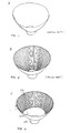
- FIGURE 1 shows a conventional parabolic reflector A.
- FIGURE 2 shows a fluted parabolic reflector B.
- the present invention provides for a new and improved reflector lamp, which overcomes the above-reference problems and others.
- a reflector lamp in accordance with one aspect of the present invention, includes first and second reflective sections.
- the first reflective section has a generally parabolic shape and a focal point and having an axis passing through the focal point. A plurality of flutes occupying a major portion of the first reflective section.
- the second reflective section has a generally concave shape which is substantially free of flutes and a focal point which is substantially coincident with the focal point of the first reflective section.
- the second reflective section is joined to the first reflective section.
- a light source is approximately centered at the focal point of the first reflective section and the focal point of the second reflective section.
- a method of forming a beam of light in which a majority of the light is within a 6° angle from an axis through the beam and is substantially free of a central hot spot includes providing a light source at the focal point of first and second reflective surfaces.
- the first reflective surface has a plurality of flutes.
- the second reflective surface is free of flutes.
- the method further includes reflecting a first portion of light emitted from the light source from the first reflective surface, the flutes distributing the light to minimize the hot spot and reflecting a second portion of light emitted from the light source from the second reflective surface, the non-fluted second reflective surface reflecting the light primarily within the 6° angle from the axis through the beam.
- One advantage of the present invention is that light is emitted within a desired beam angle of about 5 degrees.
- Another advantage of the present invention is that a smooth beam is provided with a minimized hot spot effect.
- a lamp 10 comprises a shaped reflector C comprising a housing 12 with an interior reflective coating 14 of silver, aluminum, or other suitable material so as to reflect light.
- the housing may be formed from molded or blown glass, plastic, or other suitable material.
- the reflector housing 12 includes a first end or rim 16 defining an opening 20 at the front plane of the reflector housing.
- a lens 22 is mated to the rim.
- a light source 24, such as a filament, is positioned with its longest dimension along the axis of the lamp LA.
- Lens 22 may be transparent to all light, or may include a filter to absorb/reflect the light dispersed by the light source 24. In fact, lens 22 may be designed, as known in the art, to meet the particular requirements of the lamp.
- a neck or second end 26 of reflector housing 12 includes two pass-through channels 30 and 32 which accommodate leads 34 and 36 for connecting the lamp to an external power supply (not shown). Leads 34 and 36 are in electrical connection with foils 40 and 42, which in turn are in electrical connection with leads 44 and 46. In this manner, electricity is provided to the light source 24. As shown in FIGURE 4, a filament support 48 is electrically connected with the lead 44 and the filament 24 is electrically connected with the lead 46. If desired, an envelope 52 surrounds the light source. It will be appreciated that a variety of light sources may be used with the lamp, including incandescent, arc, halogen bulb, and semiconductor light sources. As is apparent, the longitudinal axis LA of the filament 24 lies on the axis LA of the reflector housing 12.
- the concave, coated, reflective portion 56 of the reflector housing 12 includes a forward section 58, adjacent the lens, and a rear section 60, connecting the forward section with the neck 26.
- the forward section 58 is parabolic in general configuration and is fluted on its internal surface.
- the rear section 60 is a smooth, reflective portion, and is preferably ellipsoid, although a spherical or parabolic section 60 may also be used.
- the forward and rear sections are connected at a circumferential region 62, which preferably provides a smooth transition between the forward and the rear sections (i.e. the tangent at the rear section adjacent the circumferential region is the same as the tangent at the adjacent forward section).
- the filament 24 or other light source is neither infinite nor infinitesimal in size and is preferably centered at the focal point of both the parabolic, fluted section 58 and the ellipsoidal, spherical, or parabolic, non-fluted section 60.
- both the fluted section and the non-fluted section reflect light from the filament in a direction generally parallel with the axis of the lamp.
- the light passes through the lens and exits the lamp as a beam of light in which a large portion of the emitted light is within a beam angle of about 5°.
- the light is relatively uniform within the beam angle, without a significant hot spot in the center.
- the non-fluted section projects a distance n along the axis LA of the lamp from the neck and the fluted section 58 projects a distance f along the lamp axis from the non-fluted section to the lens.
- the image of the filament 24 is projected at a much larger angle ( ⁇ ) from the non-fluted section 60, than from the fluted section 58 ( ⁇ ).
- the ratio of n:f is preferably from 1:3 to 2:3, and more preferably, 1:2.
- the fluted section 58 comprises a number of flutes 64, arranged around the interior surface of the fluted section.
- the flutes preferably cover all, or the majority of the interior surface of the fluted section.
- the flutes preferably are aligned with the axis LA, although they may be at a slight angle without unduly compromising the light output.
- For a reflector housing of 4 1 ⁇ 2" (11-12 cm) diameter there are preferably between about 12 and 144 flutes 64, more preferably, 48-96 flutes, and most preferably, about 72 flutes.
- each flute comprises two generally planar faces 70, 72, which meet at an edge 74.
- the length 1 of one of the faces can be larger than that of the other face, if desired, such that the two faces reflect light at slightly different angles to improve evenness of the beam.
- FIGURE 6 a plot of luminous intensity vs. angle from the axis LA for three lamps using the reflectors A, B, C of FIGURES 1, 2, and 3 is shown.
- Reflector C had a paraboloidal rear section 60 and an n:f ratio of about 1:2, measured along the axis of the reflector.
- the plots for the three reflector shapes were calculated using a computer algorithm based on actual geometries. Data obtained from actual lamps was in agreement with the computer-generated curves.
- the candlepower distribution curve shows that A has a high value in the center, showing an undesirable hot spot.
- the intensity drops off rapidly in the desired beam angle range (0-6°, more preferably, about 0-5°), as shown by the steep slope of curve A.
- the luminous intensity is still significant. This light is essentially wasted as it misses the target.
- the hot spot effect is less than for reflector A, but the amount of wasted light directed at large angles is even greater, resulting from the negative effect of fluting close to the neck.
- the undesirable hot spot effect is minimized and the luminous intensity aimed at the target (between 0-5°) is maximized.
- the wasted luminous intensity between about 6 and 10° is minimized.
- the beneficial effects of reflector C are even more pronounced if measured by luminous flux.
Abstract
Description
- This invention relates to the lamp arts. More particularly, this invention relates to a reflector for use in reflector spot PAR reflector lamps and will be described with particular reference thereto. It should be appreciated that the invention is also applicable to reflective lamps employing a variety of light sources.
- The reflector lamps of the present invention are particularly well suited for use in spot lighting, such as headlamps, display lighting, and the like. Examples of typical reflector lamps include General Electric's PAR 30, PAR 38, and
PAR 64 lamps. PAR is the commonly accepted acronym for "parabolic aluminum reflector." Other commercially available reflector lamps may also benefit from aspects of the present invention. U.S. Patent Nos. Re.30,832; 3,010,045; 4,021,659; 4,804,878; 4,833,576; 4,855,634; 4,959,583; and 5,199,878 describe reflector lamps and methods of their manufacture. U.S. Patent No. 4,420,800 discloses reflectors with a combination of confocal spherical and parabolic shaped portions. U.S. Patent No. 4,494,176 describes a PAR lamp with a faceted parabolic reflector surface. The filament is at the focal point of the parabolic portion but not of a small adjacent neck portion of the reflector resulting in wasted light due to reflections outside the beam angle. U.S. Patent No. 5,199,787 describes a reflector lens with curved, radial flutes. FIGURE 1 shows a conventional parabolic reflector A. FIGURE 2 shows a fluted parabolic reflector B. - It has now been found that while flutes on the top of the reflector are useful in spreading filament image within the beam angle, flutes at the bottom (or neck area) of the reflector create an undesirably large spread.
- For a good spot reflector lamp it is desirable to have as much light as possible emitted in a beam of 0-5° from the axis of the lamp. Light emitted in the 6-10° range is essentially wasted. However too much light in the center (approximately 0-1°) is also undesirable, leading to uneven light distribution and burn out.
- The present invention provides for a new and improved reflector lamp, which overcomes the above-reference problems and others.
- In accordance with one aspect of the present invention, a reflector lamp is provided. The lamp includes first and second reflective sections. The first reflective section has a generally parabolic shape and a focal point and having an axis passing through the focal point. A plurality of flutes occupying a major portion of the first reflective section. The second reflective section has a generally concave shape which is substantially free of flutes and a focal point which is substantially coincident with the focal point of the first reflective section. The second reflective section is joined to the first reflective section. A light source is approximately centered at the focal point of the first reflective section and the focal point of the second reflective section.
- In accordance with another aspect of the present invention, a method of forming a beam of light in which a majority of the light is within a 6° angle from an axis through the beam and is substantially free of a central hot spot is provided. The method includes providing a light source at the focal point of first and second reflective surfaces. The first reflective surface has a plurality of flutes. The second reflective surface is free of flutes. The method further includes reflecting a first portion of light emitted from the light source from the first reflective surface, the flutes distributing the light to minimize the hot spot and reflecting a second portion of light emitted from the light source from the second reflective surface, the non-fluted second reflective surface reflecting the light primarily within the 6° angle from the axis through the beam.
One advantage of the present invention is that light is emitted within a desired beam angle of about 5 degrees. - Another advantage of the present invention is that a smooth beam is provided with a minimized hot spot effect.
- Embodiments of the invention will now be described, by way of example, with reference to the accompanying drawings, in which:
- FIGURE 1 is a perspective view of a prior art parabolic reflector;
- FIGURE 2 is a perspective view of a prior art parabolic reflector with flutes;
- FIGURE 3 is a perspective view of a reflector with a fluted parabolic section, according to the present invention;
- FIGURE 4 is a side sectional view of a lamp incorporating the reflector of FIGURE 3, showing light reflecting from fluted and non-fluted sections;
- FIGURE 5 is an enlarged front view of the reflector of FIGURE 3, showing positioning of the flutes;
- FIGURE 6 is a plot of candlelight power against beam angle relative to the reflector axis (0° being the center, along the reflector axis);
- FIGURE 7 is a schematic view of a target illuminated by light reflecting from a non-fluted forward section of the reflector housing of FIGURE 1;
- FIGURE 8 is a schematic view of a target illuminated by light reflecting from a non-fluted rear section of the reflector housing of FIGURE 1;
- FIGURE 9 is a schematic view of a target illuminated by light reflecting from a fluted forward section of the reflector housing of FIGURE 3; and
- FIGURE 10 is a schematic view of a target illuminated by light reflecting from a fluted rear section of the reflector housing of FIGURE 2.
-
- Referring now to FIGURES 3 and 4, a
lamp 10 comprises a shaped reflector C comprising ahousing 12 with an interiorreflective coating 14 of silver, aluminum, or other suitable material so as to reflect light. The housing may be formed from molded or blown glass, plastic, or other suitable material. - The
reflector housing 12 includes a first end orrim 16 defining an opening 20 at the front plane of the reflector housing. A lens 22 is mated to the rim. Alight source 24, such as a filament, is positioned with its longest dimension along the axis of the lamp LA. Lens 22 may be transparent to all light, or may include a filter to absorb/reflect the light dispersed by thelight source 24. In fact, lens 22 may be designed, as known in the art, to meet the particular requirements of the lamp. - A neck or
second end 26 ofreflector housing 12 includes two pass-throughchannels leads Leads foils leads light source 24. As shown in FIGURE 4, afilament support 48 is electrically connected with thelead 44 and thefilament 24 is electrically connected with thelead 46. If desired, anenvelope 52 surrounds the light source. It will be appreciated that a variety of light sources may be used with the lamp, including incandescent, arc, halogen bulb, and semiconductor light sources. As is apparent, the longitudinal axis LA of thefilament 24 lies on the axis LA of thereflector housing 12. - The concave, coated,
reflective portion 56 of thereflector housing 12 includes aforward section 58, adjacent the lens, and arear section 60, connecting the forward section with theneck 26. Theforward section 58 is parabolic in general configuration and is fluted on its internal surface. Therear section 60 is a smooth, reflective portion, and is preferably ellipsoid, although a spherical orparabolic section 60 may also be used. The forward and rear sections are connected at acircumferential region 62, which preferably provides a smooth transition between the forward and the rear sections (i.e. the tangent at the rear section adjacent the circumferential region is the same as the tangent at the adjacent forward section). - The
filament 24 or other light source is neither infinite nor infinitesimal in size and is preferably centered at the focal point of both the parabolic,fluted section 58 and the ellipsoidal, spherical, or parabolic, non-flutedsection 60. In this way, both the fluted section and the non-fluted section reflect light from the filament in a direction generally parallel with the axis of the lamp. The light passes through the lens and exits the lamp as a beam of light in which a large portion of the emitted light is within a beam angle of about 5°. The light is relatively uniform within the beam angle, without a significant hot spot in the center. - As shown in FIGURE 4, the non-fluted section projects a distance n along the axis LA of the lamp from the neck and the
fluted section 58 projects a distance f along the lamp axis from the non-fluted section to the lens. The image of thefilament 24 is projected at a much larger angle (α) from thenon-fluted section 60, than from the fluted section 58 (β). The ratio of n:f is preferably from 1:3 to 2:3, and more preferably, 1:2. - With reference also to FIGURE 5, the
fluted section 58 comprises a number offlutes 64, arranged around the interior surface of the fluted section. The flutes preferably cover all, or the majority of the interior surface of the fluted section. The flutes preferably are aligned with the axis LA, although they may be at a slight angle without unduly compromising the light output. For a reflector housing of 4 ½" (11-12 cm) diameter there are preferably between about 12 and 144flutes 64, more preferably, 48-96 flutes, and most preferably, about 72 flutes. In a preferred embodiment, each flute comprises two generally planar faces 70, 72, which meet at an edge 74. Thelength 1 of one of the faces can be larger than that of the other face, if desired, such that the two faces reflect light at slightly different angles to improve evenness of the beam. - With reference now to FIGURE 6, a plot of luminous intensity vs. angle from the axis LA for three lamps using the reflectors A, B, C of FIGURES 1, 2, and 3 is shown. Reflector C had a paraboloidal
rear section 60 and an n:f ratio of about 1:2, measured along the axis of the reflector. The plots for the three reflector shapes were calculated using a computer algorithm based on actual geometries. Data obtained from actual lamps was in agreement with the computer-generated curves. - As shown in FIGURE 6, the candlepower distribution curve shows that A has a high value in the center, showing an undesirable hot spot. The intensity drops off rapidly in the desired beam angle range (0-6°, more preferably, about 0-5°), as shown by the steep slope of curve A. However, at large angles (above about 7°) the luminous intensity is still significant. This light is essentially wasted as it misses the target.
- For reflector B, the hot spot effect is less than for reflector A, but the amount of wasted light directed at large angles is even greater, resulting from the negative effect of fluting close to the neck.
- In the optimized embodiment of reflector C, the undesirable hot spot effect is minimized and the luminous intensity aimed at the target (between 0-5°) is maximized. The wasted luminous intensity (between about 6 and 10°) is minimized. The beneficial effects of reflector C are even more pronounced if measured by luminous flux.
- With reference to FIGURES 7 - 10, theoretical projected images of the filament versus a
target illumination area 80 are shown for various lamp designs to show the benefits of a flutedforward section 58.Images 82 fromsection 58 of the reflector, if it were not fluted, would overlap as shown in FIGURE 7, causing ahot spot 84 in the middle. Conversely,images 86 from thesection 60 closer to thefilament 24, partially fall outside the target, as shown in FIGURE 8. Fluting ofsection 58 results in a more even distribution of thefilament images 88, resulting in more uniform illumination, as shown in FIGURE 9. However, fluting ofsection 60 causes more light to fall outside the target area, as shown in FIGURE 10, since thefilament images 90 are deflected even further away from the center, as compared with FIGURE 8. The optimum combination for minimizing wasted light and providing uniform illumination is achieved by combining the a non fluted rear section 60 (FIGURE 8) and a fluted forward section 58 (FIGURE 9).
Claims (10)
- A reflector lamp comprising:a first reflective section having a generally parabolic shape and a focal point and having an axis passing through the focal point, a plurality of flutes occupying a major portion of the first reflective section;a second reflective section having a generally concave shape which is substantially free of flutes and a focal point which is substantially coincident with the focal point of the first reflective section, said second reflective section being joined to said first reflective section;a light source approximately centered at the focal point of the first reflective section and the focal point of the second reflective section.
- The lamp of claim 1, wherein the light source is axially aligned relative to the axis of the first reflective section.
- The lamp of claim 1, further including a lens located at an open end of the first reflective section.
- The lamp of claim 1, wherein the first reflective section projects a distance f along the axis and the second reflective section extends a distance n along the axis and wherein the ratio n:f is between about 1:3 and 2:3.
- The lamp of claim 4, wherein the ratio n:f is about 1:2.
- The lamp of claim 1, wherein there are from 12 to 144 flutes.
- The lamp of claim 1, wherein there is a smooth transition region between the first and second reflective sections.
- The lamp of claim 1, wherein the second reflective section is one of parabolic, spherical, and ellipsoidal.
- A method of forming a beam of light in which a majority of the light is within a 6° angle from an axis through the beam and is substantially free of a central hot spot, the method comprising:providing a light source at the focal point of first and second reflective surfaces, the first reflective surface having a plurality of flutes, the second reflective surface being free of flutes;reflecting a first portion of light emitted from the light source from the first reflective surface, the flutes distributing the light to minimize the hot spot;reflecting a second portion of light emitted from the light source from the second reflective surface, the non-fluted second reflective surface reflecting the light primarily within the 6° angle from the axis through the beam.
- The method of claim 9, wherein the first portion of light is of greater luminous intensity than the second portion of light.
Applications Claiming Priority (2)
| Application Number | Priority Date | Filing Date | Title |
|---|---|---|---|
| US09/370,832 US6168293B1 (en) | 1999-08-09 | 1999-08-09 | Spot par reflector lamp |
| US370832 | 1999-08-09 |
Publications (1)
| Publication Number | Publication Date |
|---|---|
| EP1076203A2 true EP1076203A2 (en) | 2001-02-14 |
Family
ID=23461376
Family Applications (1)
| Application Number | Title | Priority Date | Filing Date |
|---|---|---|---|
| EP00306782A Withdrawn EP1076203A2 (en) | 1999-08-09 | 2000-08-09 | Spot par reflector lamp |
Country Status (4)
| Country | Link |
|---|---|
| US (1) | US6168293B1 (en) |
| EP (1) | EP1076203A2 (en) |
| JP (1) | JP2001101906A (en) |
| CN (1) | CN1321849A (en) |
Cited By (8)
| Publication number | Priority date | Publication date | Assignee | Title |
|---|---|---|---|---|
| EP1500866A2 (en) * | 2003-07-25 | 2005-01-26 | Osram Sylvania Inc. | Reflector lamp with a high domed lens |
| EP1635379A1 (en) | 2004-09-14 | 2006-03-15 | Flowil International Lighting (Holding) B.V. | Reflector lamp |
| WO2007118044A1 (en) * | 2006-04-06 | 2007-10-18 | General Electric Company | High-intensity discharge lamp for spot lighting |
| EP1862729A1 (en) | 2006-05-30 | 2007-12-05 | Ushiodenki Kabushiki Kaisha | Light source device |
| EP1906435A3 (en) * | 2006-09-27 | 2010-11-24 | Osram-Sylvania Inc. | Compact par lamp |
| EP2320129A1 (en) * | 2009-11-06 | 2011-05-11 | Auer Lighting GmbH | Reflector lamp |
| WO2014107463A1 (en) * | 2013-01-02 | 2014-07-10 | Cunningham David W | Lighting fixtrue and light-emitting diode light source assembly |
| CN111486353A (en) * | 2020-04-26 | 2020-08-04 | 扬德电气集团有限公司 | Reflection type L ED lamp and solar street lamp applying same |
Families Citing this family (18)
| Publication number | Priority date | Publication date | Assignee | Title |
|---|---|---|---|---|
| JP2001201623A (en) * | 2000-01-20 | 2001-07-27 | Fujitsu General Ltd | Illumination light source device |
| US6953261B1 (en) * | 2000-02-25 | 2005-10-11 | North American Lighting, Inc. | Reflector apparatus for a tubular light source |
| US6508562B1 (en) | 2001-11-05 | 2003-01-21 | Yazaki North America, Inc. | Instrument cluster reflector |
| JP4461019B2 (en) * | 2002-11-27 | 2010-05-12 | コーニンクレッカ フィリップス エレクトロニクス エヌ ヴィ | Electric lamp / reflector unit |
| US7131749B2 (en) * | 2003-08-21 | 2006-11-07 | Randal Lee Wimberly | Heat distributing hybrid reflector lamp or illumination system |
| US7303316B2 (en) * | 2005-08-30 | 2007-12-04 | Mei-Chen Liu | Car lamp structure |
| US20080043470A1 (en) * | 2006-08-17 | 2008-02-21 | Randal Lee Wimberly | Reflector lamp or illumination system |
| KR100806598B1 (en) * | 2006-09-30 | 2008-02-27 | 류형수 | High lux reflector plate structure of illumination lamp |
| WO2009067843A1 (en) * | 2007-11-28 | 2009-06-04 | Tony Chunlung Young | Multi-reflector mechanism for a led light source |
| KR101102770B1 (en) | 2009-08-20 | 2012-01-05 | 김기정 | A reflecting shade |
| US9151469B2 (en) * | 2010-04-09 | 2015-10-06 | Koninklijke Philips N.V. | Lighting device having a smooth cut-off |
| CN102705778A (en) * | 2011-03-28 | 2012-10-03 | 海洋王照明科技股份有限公司 | Light-reflecting cup and lighting lamp |
| WO2014156668A1 (en) * | 2013-03-27 | 2014-10-02 | 株式会社小糸製作所 | Lighting device for vehicle |
| JP6106000B2 (en) * | 2013-03-27 | 2017-03-29 | 株式会社小糸製作所 | Vehicle lamp |
| CN104075247A (en) * | 2013-03-28 | 2014-10-01 | 海洋王(东莞)照明科技有限公司 | Reflector component and lamp structure thereof |
| CN104075246B (en) * | 2013-03-29 | 2016-06-29 | 海洋王(东莞)照明科技有限公司 | Mine lamp reflector and there is the illuminator of this mine lamp reflector |
| CN103471017B (en) * | 2013-09-16 | 2016-06-01 | 深圳市中电金台光电科技有限公司 | Automotive LED headlamp |
| CN105605499A (en) * | 2014-11-24 | 2016-05-25 | 欧普照明股份有限公司 | Multi-combination down lamp |
Citations (10)
| Publication number | Priority date | Publication date | Assignee | Title |
|---|---|---|---|---|
| US3010045A (en) | 1955-05-27 | 1961-11-21 | Westinghouse Electric Corp | Sealed-beam lamp and method of manufacture |
| US4021659A (en) | 1975-10-30 | 1977-05-03 | General Electric Company | Projector lamp reflector |
| USRE30832E (en) | 1976-08-30 | 1981-12-22 | General Electric Company | Ellipsoidal reflector lamp |
| US4420800A (en) | 1980-12-22 | 1983-12-13 | General Electric Company | Reflector lamp with shaped reflector and lens |
| US4494176A (en) | 1984-03-14 | 1985-01-15 | General Electric Company | Lamps having multiple and aimed parabolic sections for increased useful light output |
| US4804878A (en) | 1987-02-05 | 1989-02-14 | Gte Products Corporation | Electric lamp, base for use therewith and method of assembling same |
| US4833576A (en) | 1987-09-29 | 1989-05-23 | General Electric Company | Aluminum phosphate cement compositions and lamp assemblies containing same |
| US4855634A (en) | 1985-12-19 | 1989-08-08 | Gte Products Corporation | Reflector and eyelet construction for reflector-type lamps |
| US4959583A (en) | 1989-03-31 | 1990-09-25 | General Electric Company | Reflective lamps having an improved light source mounting arrangement |
| US5199878A (en) | 1990-11-15 | 1993-04-06 | Adc Telecommunications, Inc. | Plug-in jack card for normally closed contacts |
Family Cites Families (5)
| Publication number | Priority date | Publication date | Assignee | Title |
|---|---|---|---|---|
| US4277821A (en) * | 1976-06-24 | 1981-07-07 | Sassmannshausen Knut | Lamp |
| US4447865A (en) * | 1982-05-13 | 1984-05-08 | General Electric Company | Reflector lamp |
| US4506316A (en) * | 1983-08-18 | 1985-03-19 | Gte Products Corporation | Par spot lamp |
| US5177396A (en) * | 1990-12-19 | 1993-01-05 | Gte Products Corporation | Mirror with dichroic coating lamp housing |
| US5199787A (en) * | 1992-01-08 | 1993-04-06 | North American Philips Corporation | Reflector lamp having improved lens |
-
1999
- 1999-08-09 US US09/370,832 patent/US6168293B1/en not_active Expired - Lifetime
-
2000
- 2000-08-07 JP JP2000237842A patent/JP2001101906A/en not_active Withdrawn
- 2000-08-09 EP EP00306782A patent/EP1076203A2/en not_active Withdrawn
- 2000-08-09 CN CN00122757A patent/CN1321849A/en active Pending
Patent Citations (10)
| Publication number | Priority date | Publication date | Assignee | Title |
|---|---|---|---|---|
| US3010045A (en) | 1955-05-27 | 1961-11-21 | Westinghouse Electric Corp | Sealed-beam lamp and method of manufacture |
| US4021659A (en) | 1975-10-30 | 1977-05-03 | General Electric Company | Projector lamp reflector |
| USRE30832E (en) | 1976-08-30 | 1981-12-22 | General Electric Company | Ellipsoidal reflector lamp |
| US4420800A (en) | 1980-12-22 | 1983-12-13 | General Electric Company | Reflector lamp with shaped reflector and lens |
| US4494176A (en) | 1984-03-14 | 1985-01-15 | General Electric Company | Lamps having multiple and aimed parabolic sections for increased useful light output |
| US4855634A (en) | 1985-12-19 | 1989-08-08 | Gte Products Corporation | Reflector and eyelet construction for reflector-type lamps |
| US4804878A (en) | 1987-02-05 | 1989-02-14 | Gte Products Corporation | Electric lamp, base for use therewith and method of assembling same |
| US4833576A (en) | 1987-09-29 | 1989-05-23 | General Electric Company | Aluminum phosphate cement compositions and lamp assemblies containing same |
| US4959583A (en) | 1989-03-31 | 1990-09-25 | General Electric Company | Reflective lamps having an improved light source mounting arrangement |
| US5199878A (en) | 1990-11-15 | 1993-04-06 | Adc Telecommunications, Inc. | Plug-in jack card for normally closed contacts |
Cited By (14)
| Publication number | Priority date | Publication date | Assignee | Title |
|---|---|---|---|---|
| EP1500866A3 (en) * | 2003-07-25 | 2005-11-02 | Osram Sylvania Inc. | Reflector lamp with a high domed lens |
| EP1500866A2 (en) * | 2003-07-25 | 2005-01-26 | Osram Sylvania Inc. | Reflector lamp with a high domed lens |
| EP1635379A1 (en) | 2004-09-14 | 2006-03-15 | Flowil International Lighting (Holding) B.V. | Reflector lamp |
| US7517115B2 (en) | 2004-09-14 | 2009-04-14 | Flowil International Lighting (Holding) B.V. | Reflector lamp |
| RU2443937C2 (en) * | 2006-04-06 | 2012-02-27 | Дженерал Электрик Компани | Gas-discharge tube of high intensity for directional light |
| WO2007118044A1 (en) * | 2006-04-06 | 2007-10-18 | General Electric Company | High-intensity discharge lamp for spot lighting |
| EP1862729A1 (en) | 2006-05-30 | 2007-12-05 | Ushiodenki Kabushiki Kaisha | Light source device |
| EP1906435A3 (en) * | 2006-09-27 | 2010-11-24 | Osram-Sylvania Inc. | Compact par lamp |
| EP2320129A1 (en) * | 2009-11-06 | 2011-05-11 | Auer Lighting GmbH | Reflector lamp |
| US8931926B2 (en) | 2009-11-06 | 2015-01-13 | Auer Lighting Gmbh | Reflector luminaire |
| WO2014107463A1 (en) * | 2013-01-02 | 2014-07-10 | Cunningham David W | Lighting fixtrue and light-emitting diode light source assembly |
| US9261241B2 (en) | 2013-01-02 | 2016-02-16 | David W. Cunningham | Lighting fixture and light-emitting diode light source assembly |
| US9273831B2 (en) | 2013-01-02 | 2016-03-01 | David W. Cunningham | Lighting fixture and light-emitting diode light source assembly |
| CN111486353A (en) * | 2020-04-26 | 2020-08-04 | 扬德电气集团有限公司 | Reflection type L ED lamp and solar street lamp applying same |
Also Published As
| Publication number | Publication date |
|---|---|
| US6168293B1 (en) | 2001-01-02 |
| CN1321849A (en) | 2001-11-14 |
| JP2001101906A (en) | 2001-04-13 |
Similar Documents
| Publication | Publication Date | Title |
|---|---|---|
| US6168293B1 (en) | Spot par reflector lamp | |
| US4494176A (en) | Lamps having multiple and aimed parabolic sections for increased useful light output | |
| CA1203219A (en) | Lighting fixture reflector | |
| US5971571A (en) | Concave light reflector device | |
| US4654758A (en) | Headlamp | |
| US20050168995A1 (en) | Fresnel lens spotlight with coupled variation of the spacing of lighting elements | |
| US20080043470A1 (en) | Reflector lamp or illumination system | |
| US5556191A (en) | Electric reflector lamp | |
| JP2003031011A (en) | Linear light source for lighting fixture | |
| JPH09237504A (en) | Automobile headlight for downward and upward light | |
| US20050135106A1 (en) | Fresnel lens spotlight with coupled variation of the spacing of lighting elements | |
| US20050041430A1 (en) | Heat distributing hybrid reflector lamp or illumination system | |
| US20050162750A1 (en) | Fresnel lens spotlight | |
| US5645344A (en) | Luminaire | |
| US6739737B2 (en) | Lamp body for a fluorescent compact spot and flood light source | |
| JPS63226871A (en) | Incandescent lamp and its globe | |
| JP2004206957A (en) | Vehicular lighting fixture | |
| CA1172682A (en) | Reflector lamp | |
| JPS62213062A (en) | Blow lamp bulb and incandescent lamp using the same | |
| JP4168357B2 (en) | Lamp | |
| JPS6118303B2 (en) | ||
| JP2002170409A (en) | Headlight | |
| US20060044805A1 (en) | Luminaire with reflector having two portions with different optical axes | |
| US5345140A (en) | Electric lamp arrangement with reflector | |
| JPH0463364B2 (en) |
Legal Events
| Date | Code | Title | Description |
|---|---|---|---|
| PUAI | Public reference made under article 153(3) epc to a published international application that has entered the european phase |
Free format text: ORIGINAL CODE: 0009012 |
|
| AK | Designated contracting states |
Kind code of ref document: A2 Designated state(s): AT BE CH CY DE DK ES FI FR GB GR IE IT LI LU MC NL PT SE |
|
| AX | Request for extension of the european patent |
Free format text: AL;LT;LV;MK;RO;SI |
|
| RIN1 | Information on inventor provided before grant (corrected) |
Inventor name: COLLINS, EDWARD JOSEPH Inventor name: LIESZKOVSZKY, LASZLO VIKTOR Inventor name: BRANN, JACOB Inventor name: SKILSKYJ, LUDWIG |
|
| STAA | Information on the status of an ep patent application or granted ep patent |
Free format text: STATUS: THE APPLICATION HAS BEEN WITHDRAWN |
|
| 18W | Application withdrawn |
Effective date: 20030306 |