EP1077112A2 - Device for clamping workpieces - Google Patents
Device for clamping workpieces Download PDFInfo
- Publication number
- EP1077112A2 EP1077112A2 EP00114959A EP00114959A EP1077112A2 EP 1077112 A2 EP1077112 A2 EP 1077112A2 EP 00114959 A EP00114959 A EP 00114959A EP 00114959 A EP00114959 A EP 00114959A EP 1077112 A2 EP1077112 A2 EP 1077112A2
- Authority
- EP
- European Patent Office
- Prior art keywords
- base element
- clamping
- workpiece
- piston
- workpieces
- Prior art date
- Legal status (The legal status is an assumption and is not a legal conclusion. Google has not performed a legal analysis and makes no representation as to the accuracy of the status listed.)
- Granted
Links
Images


Classifications
-
- B—PERFORMING OPERATIONS; TRANSPORTING
- B25—HAND TOOLS; PORTABLE POWER-DRIVEN TOOLS; MANIPULATORS
- B25B—TOOLS OR BENCH DEVICES NOT OTHERWISE PROVIDED FOR, FOR FASTENING, CONNECTING, DISENGAGING OR HOLDING
- B25B11/00—Work holders not covered by any preceding group in the subclass, e.g. magnetic work holders, vacuum work holders
- B25B11/005—Vacuum work holders
- B25B11/007—Vacuum work holders portable, e.g. handheld
-
- B—PERFORMING OPERATIONS; TRANSPORTING
- B25—HAND TOOLS; PORTABLE POWER-DRIVEN TOOLS; MANIPULATORS
- B25B—TOOLS OR BENCH DEVICES NOT OTHERWISE PROVIDED FOR, FOR FASTENING, CONNECTING, DISENGAGING OR HOLDING
- B25B5/00—Clamps
- B25B5/06—Arrangements for positively actuating jaws
- B25B5/061—Arrangements for positively actuating jaws with fluid drive
Definitions
- the invention relates to a device for tensioning Workpieces for cutting or non-cutting processing.
- Plastics, light metals or wood substitutes belongs to a machine tool with at least three perpendicular axes of the X, Y and Z axes, movable machining head.
- the workpieces as a rule plate-like or strip-like, are on corresponding Machining stations adjusted so that a collision of the Adjustment and holding device with the Machining tools is excluded as far as possible.
- Vacuum clamping devices To the mostly plate-shaped workpieces in any Position in the X, Y machining plane of the machine tool to adjust and hold are so-called Vacuum clamping devices used.
- This Vacuum clamping devices generally as vacuum blocks or Suction clamps include one or more Basic elements that have a lower, marginal on their underside Sealed suction field for fixing on the top of a Have workpiece space on a machine tool. At hers The top is also an edge sealed suction field provided that serves for suction clamping of the workpieces.
- suction clamps are usually two vacuum lines connectable, one of which is connected to the upper one Suction field and the other connected to the lower suction field becomes.
- the flexible arrangement of the suction clamps enables that workpieces of any geometry along their edges can be edited and the whole Workpiece clamping device is not damaged. Further is the workpiece is easily accessible all around.
- Such vacuum chucks are known in the art for the workpiece location of a machine tool, in particular for Processing of plate-shaped workpieces made of wood or woody materials, well known.
- the suction clamps are thereby parallel to each other, transversely towards one of the Machining axes, e.g. the X axis, adjustable bars in Positioned in the direction of the Y axis.
- the plate-shaped Workpieces are attached to the upper suction field attached to the upper, accessible side of the suction clamp.
- German patent DE 44 04 513 C1 there is one described such a vacuum chuck in which the Vacuum lines in the area of the workpiece support safely and are arranged trouble-free. These are in the bars in Two vacuum channels arranged in the longitudinal direction and each of these Vacuum channels with a longitudinal row of suction openings on the Top of the respective bar via flow valves connected. Compared to other systems that supply vacuum Use flexible hoses is by the in the DE 44 04 413 C1 described a configuration Clamping device for plate-shaped workpieces created, which have largely trouble-free access to the workpiece enables.
- the invention has for its object a device for clamping workpieces that create the safe Clamping of strip-shaped work pieces enables and at the same time, secure and trouble-free accessibility guaranteed.
- the invention is based on the idea of taking advantage of positionable suction clamps when machining to use strip-like workpieces.
- the basic element which has a lower, edge sealed suction field for fixation on the Top of a beam or on the workpiece position of one Has machine tool, integrated a piston assembly.
- This piston arrangement is with a for clamping strip-like workpieces made of wood, plastics, wood-like materials or light metals Furnishings.
- the piston arrangement is like this designed that a workpiece between the in the installed position upper end of the piston assembly and the top of the Basic element can be tensioned.
- This combination of vacuum clamping device and device for clamping strips offers the advantages of Vacuum clamping devices for plate-shaped components are known are, also for strip-shaped components. So they can Suction clamps flexible at any point on the Workpiece rest can be arranged, which is a good one Accessibility to the workpiece for machining, e.g. Milling, sawing, drilling, or non-cutting processing, e.g. Bending, gluing or the like.
- the Clamping device can also be positioned quickly and safely against slipping on the workpiece position Attach machine tool.
- the device for clamping workpieces after one advantageous embodiment a piston arrangement in such a way that the underside of the Piston arrangement with the side walls of the base element and the bottom wall of the base element an evacuable cavity forms.
- This embodiment has the advantage that the Piston arrangement is movable by evacuating the cavity.
- the vacuum supply to evacuate the cavity in the floor area of the Basic element attached.
- the positioning of the Vacuum supply e.g. consists of hoses, near the Workpiece space and as far as possible from the Workpiece clamping level causes a largely undisturbed Accessibility to the workpiece.
- the vacuum supply for evacuating the Cavity through the bottom wall of the base element A Vacuum supply through the bottom wall of the base element and further through correspondingly provided vacuum channels in the bars of the Workpiece space avoid impairing the Accessibility to the workpiece through vacuum hoses or similar completely.
- the chip removal in case of cutting Editing is also not hindered by this.
- Suction openings and obstructing or blocking the air inlet Flow valves can be used without retrofitting continue to be used.
- the device for tensioning advantageously has Workpieces at least two separately switchable Vacuum circles.
- Two separately switchable vacuum circuits can suction and attach the suction clamp done in a first step and the positioning of the Workpiece on the device is independent of the Attachment of the suction clamp and can be done in a separate Work step happen.
- the device for clamping workpieces on the suction clamp Clamp is well known in the art Devices to secure components of various geometries to hold on. Last-shaped components can go through Clamping claws can also be attached well.
- the clamping claw is preferably on the piston arrangement rotatably attached. This in turn serves a larger one Flexibility in positioning the workpiece.
- the clamping claw is advantageously asymmetrical educated.
- the more suitable part of the clamping claw selected for tensioning and the other part unused or two workpieces can remain at the same time, too different geometries.
- the Clamping claw two clamping legs of different lengths.
- two clamping legs are two workpieces can be clamped and edited at the same time, whereby by a different length of the clamping leg is achieved that depending on the geometry of the workpiece or workpieces the appropriate clamping leg assigned to the workpiece can be held and thus the workpiece is held very securely becomes.
- the clamping claw is advantageously on its underside provided with an elastic coating. This Coating prevents the workpiece from slipping and reduces the risk of damage to the workpiece hard parts of the clamping device.
- the device for tensioning comprises Workpieces a return spring for the piston assembly.
- a return spring for the piston assembly is the Clamping device when the vacuum circuit to move the Piston assembly is not active in an open state held. This means that workpieces can be easily inserted into the Clamping device can be inserted or from it can be removed.
- the device for tensioning preferably comprises Workpieces at least one adjustment stop for the Workpiece.
- Such an adjustment stop has the advantage that workpieces that are on their unworkable side for example, tiered, lighter and firmer can be.
- the adjustment stop is preferably for the workpiece releasably on the device for clamping Workpieces attached. This enables that depending on a suitable geometry of the workpiece to be machined Adjustment stop can be selected and used.
- Basic element essentially made of plastic.
- the usage of plastic for the basic element enables a inexpensive manufacture of the basic element and also offers the advantage that the risk of damage to the Machine tool or the tool at one unintentional collision with the basic element far is less than with harder materials, such as Steel.
- the stand has of the basic element one or more adjustment stops.
- This Adjustment stops serve for exact alignment of the Basic element. When using such adjustment stops only the adjustment stops have to be made extremely accurately to ensure precise alignment of the basic element on the Ensure machine tool. This offers one Price advantage over the adjustment by means of larger ones Areas of the actual floor area of the base element that then must be made to fit overall.
- the base element preferably has the workpiece facing surface has a ventilation opening.
- This Ventilation opening serves to equalize the pressure at the Evacuation through the bottom wall, the side walls of the Basic element and the piston limited cavity.
- a positioning aid is advantageously on the basic element attached for the basic element. This positioning aid facilitates the positioning of the basic element on the Workplace location of a machine tool.
- the Piston arrangement of a piston rod and one Piston plate The structure of the piston assembly from the piston rod and piston plate allows different geometries of the Basic element by adapting the shape of the piston plate can be used.
- the piston rod can act as a stop be used for the workpiece and takes the actual one Clamping device on.
- the piston plate serves the Sealing of the base plate by base plate, Side walls of the base element and piston arrangement defined Cavity that is suitable for evacuation.
- sealing arrangement for sealing against the side walls of the basic element attached.
- the sealing arrangement is like this trained that on the one hand they slide the Piston arrangement along the base element allows on the other hand for reliable sealing of the evacuable cavity.
- one conventional sealing arrangement e.g. an O-ring, allows for a seal through for example, good tolerance tolerance inexpensive sealing of the cavity.
- the device for tensioning preferably comprises Workpieces a guide element for the piston rod.
- a guide element becomes the danger of tilting or Reduced twisting of the piston rod and a one-sided Clamping a workpiece in the arrangement allows.
- the guidance of the piston rod can accommodate the Return spring for the piston assembly.
- the guide element is advantageously for the Piston rod in the evacuable cavity of the basic element attached. This offers the advantage of a compact design the arrangement and also the lowest possible Impairment of accessibility to the work to be done Workpiece.
- Fig. 1 is a first embodiment of the device for Clamping workpieces 50 shown, two different workpieces 33, 34 are clamped.
- the device comprises a basic element 10, which has a Bottom wall 17 on the footprint 32 in the workpiece position can be attached.
- the attachment of the base element 10 for machining on the workpiece position of a machine tool or non-cutting machining of workpieces, e.g. Drill, Milling, sawing or gluing and bending takes place at the illustrated embodiment of the basic element via a Row of suction openings on top of a beam the workpiece location of a machine tool, which with the Vacuum devices 31 in the bottom area of the base element interact.
- the vacuum supply 19 to the suction openings in Workpiece space that corresponds to a first vacuum circuit shown schematically.
- This basic element can be in one another embodiment (not shown) instead of directly via suction openings with valves on the beams of the Machine tool to be evacuable, also from the side attached hoses are evacuated. However, arises then some interference from the hoses Accessibility to the workpiece.
- the base element 10 is shown in FIG Embodiment a positioning aid 28 attached.
- This Positioning aid serves to put the basic element on for this provided bar of the workpiece location Align machine tool in X, Y plane. This Operation can either be done by hand or under Using robots.
- the basic element 10 is by means of the adjustment stops 27 on the workpiece position Machine tool aligned with the horizontal.
- Piston arrangement 13 In this basic element 10, which in the technical language with Suction clamp or vacuum block is one Piston arrangement 13 integrated.
- the piston assembly 13 is made from a piston rod 14 and a piston plate 15. Die Piston rod 14 is in the installed position through an opening Out top of the base element.
- the piston plate 15 is designed so that they essentially the geometry of the Floor area of the base element 10 corresponds and thus a Type partition between the bottom wall of the base element 10 and creates the upper wall of the base element 10.
- evacuable cavity 11 is on the side surface the piston plate 15 all around a sealing device 30 appropriate.
- the sealing device 30 can, for example, be a Rubber seal, like an O-ring. It can of course, any other standard in technology Seal are used, which is simultaneously a sliding of the Piston plate 15 along the side wall of base member 10 enables.
- a return spring 25 is attached in the guide device 12 for the piston device 13 .
- This return spring 25 acts so that the piston assembly 13 of the Return spring is held in a position by this is characterized in that the distance between the top of the Piston device 13 and top of base element 10 is larger than a workpiece 33, 34 to be machined.
- a Fastener 16 for example a conventional one Can be screw, a clamping claw 20 attached.
- the Fastening element 16 is advantageously designed that the clamping claw 20 in any angular position can be fixed and therefore extremely flexible with regard to of clamping the workpiece. Clamp securely around workpieces to be able to have the clamping claw preferably on her Underside of an elastic coating 21. This elastic Coating serves to prevent the workpiece 33, 34 from slipping largely excluded and also the workpiece against To protect damage from the clamping claw.
- the clamping claw shown in Fig. 1 is asymmetrical trained and has a shorter clamping leg 22 and a longer clamping leg 23. This design increases the Flexibility in configuration and geometry of the Workpieces 33, 34.
- 34 includes the device further includes one or more adjustment stops for the workpiece or the workpieces.
- This adjustment stop 29 is not fixed to the base element 10 or Piston device 13 connected. That enables one easy replacement of the adjustment stop 29 depending on the Geometry of the workpiece 33.
- the base element 10 comprises a ventilation opening 26.
- Fig. 2 is a similar device for tensioning Workpieces as shown in Fig. 1.
- the vacuum supply too through the bottom wall and side walls of the base element 10 as well as piston plate 15 defined cavity is so designed to pass through the bottom wall of base member 10 runs through and on the footprint 32 of the Basic element 10 with suction openings on the top of a Bar on the workpiece location of a machine tool interacts, and so the connection between vacuum supply 18 and evacuable cavity 11 is produced. Thereby hoses on the workpiece table are completely eliminated.
- Fig. 3 is a plan view of a device for Clamping workpieces as shown in Fig. 1 or 2 is presented, layed out.
- the clamp 20 is in any Angular position by the fastener 16, about one Screw, adjustable. This enables great flexibility when clamping a workpiece.
- the Suction clamp which is essentially the base element 10 corresponds to a designated place on one Bars of a workpiece location of a machine tool is aligned with the aid of the adjusting devices 27, 28. Then a first vacuum circuit is activated so that the base element 10 through the vacuum spaces 31 and Vacuum feeder 19 on the workpiece position Machine tool is fixed. The exact positioning of the Basic element 10 in the X, Y plane happens beforehand via the Positioning aid 28.
- a Vacuum supply 18, 24 activated a second vacuum circuit, so that through the bottom wall of the base element, the side walls of the base element 10 and the piston plate 15 formed Cavity is evacuated.
- the vacuum in evacuated room 11 is ensured unintentional loosening of the workpiece, that too strip-shaped workpiece can be excluded.
- the vacuum is evacuated Cavity 11 deactivated via the feed devices 18, 24, the spring force of the return spring 25 can thus Piston device 13 and the clamping claw 20 upwards press and the workpiece can be removed from the device become.
- Clamping workpieces lies in the fact that also strip-shaped Components can be clamped, and still the advantages the clamping of workpieces with suction clamps remain, especially the good accessibility to the workpiece.
- the embodiment is completely tubeless and therefore very flexible. The machining resulting chips can also not be in the hoses Caught for delivery to the evacuation units.
- the system offers a high level of security with regard to the Fastening of the workpieces, since a vacuum query is possible Can easily and reliably determine faults. This in turn reduces the risk of accidents.
Abstract
Description
Die Erfindung betrifft eine Vorrichtung zum Spannen von Werkstücken für spanende oder spanlose Bearbeitung.The invention relates to a device for tensioning Workpieces for cutting or non-cutting processing.
Zu einem Bearbeitungsplatz für Werkstücke aus Holz, Kunststoffen, Leichtmetallen oder Holzaustauschstoffen, gehört eine Werkzeugmaschine mit einem zumindest in drei senkrecht zueinander stehenden Achsen der X-, Y- und Z-Achse, verfahrbaren Bearbeitungskopf. Die Werkstücke, in der Regel plattenförmig oder leistenförmig, werden auf entsprechenden Bearbeitungsplätzen so justiert, daß eine Kollision der Justier- und Festhaltevorrichtung mit den Bearbeitungswerkzeugen möglichst ausgeschlossen ist.To a processing station for wooden workpieces, Plastics, light metals or wood substitutes, belongs to a machine tool with at least three perpendicular axes of the X, Y and Z axes, movable machining head. The workpieces, as a rule plate-like or strip-like, are on corresponding Machining stations adjusted so that a collision of the Adjustment and holding device with the Machining tools is excluded as far as possible.
Um die meist plattenförmigen Werkstücke in einer beliebigen Position in der X-, Y-Bearbeitungsebene der Werkzeugmaschine zu justieren und festzuhalten, werden sogenannte Vakuumspannvorrichtungen eingesetzt. Diese Vakuumspannvorrichtungen, allgemein als Blocksauger oder Saugspanner bezeichnet, umfassen ein oder mehrere Grundelemente, die auf ihrer Unterseite ein unteres, randlich abgedichtetes Saugfeld zur Fixierung auf der Oberseite eines Werkstückplatzes einer Werkzeugmaschine besitzen. An ihrer Oberseite ist ebenfalls ein randlich abgedichtetes Saugfeld vorgesehen, das zum Saugspannen der Werkstücke dient. An diesen Saugspannern sind in der Regel zwei Vakuumleitungen anschließbar, von denen die eine jeweils mit dem oberen Saugfeld und die andere mit dem unteren Saugfeld verbunden wird. Die flexible Anordnung der Saugspanner ermöglicht es, daß Werkstücke beliebiger Geometrien entlang ihrer Kanten bearbeitet werden können und dabei die gesamte Werkstückspannvorrichtung nicht beschädigt wird. Ferner ist das Werkstück rundum gut zugänglich.To the mostly plate-shaped workpieces in any Position in the X, Y machining plane of the machine tool to adjust and hold are so-called Vacuum clamping devices used. This Vacuum clamping devices, generally as vacuum blocks or Suction clamps include one or more Basic elements that have a lower, marginal on their underside Sealed suction field for fixing on the top of a Have workpiece space on a machine tool. At hers The top is also an edge sealed suction field provided that serves for suction clamping of the workpieces. On These suction clamps are usually two vacuum lines connectable, one of which is connected to the upper one Suction field and the other connected to the lower suction field becomes. The flexible arrangement of the suction clamps enables that workpieces of any geometry along their edges can be edited and the whole Workpiece clamping device is not damaged. Further is the workpiece is easily accessible all around.
In der Technik sind derartige Vakuumspannvorrichtungen für den Werkstückplatz einer Werkzeugmaschine, insbesondere zum Bearbeiten von plattenförmigen Werkstücken aus Holz oder holzartigen Werkstoffen, gut bekannt. Die Saugspanner werden dabei auf zueinander parallelen, quer in Richtung einer der Bearbeitungsachsen, z.B. der X-Achse, verstellbaren Balken in Richtung der Y-Achse positionierbar aufgesetzt. Mit Hilfe des unteren Saugfeldes werden die Grundelemente auf dem Balken der Werkzeugmaschine befestigt. Die plattenförmigen Werkstücke werden mit Hilfe des oberen Saugfelds an der oberen, zugänglichen Seite des Saugspanners befestigt. Durch die zwei unabhängigen Saugfelder ist die Fixierung der Grundelemente auf dem Balken und das Spannen der Werkstücke getrennt steuerbar.Such vacuum chucks are known in the art for the workpiece location of a machine tool, in particular for Processing of plate-shaped workpieces made of wood or woody materials, well known. The suction clamps are thereby parallel to each other, transversely towards one of the Machining axes, e.g. the X axis, adjustable bars in Positioned in the direction of the Y axis. With the help of bottom suction field are the basic elements on the bar attached to the machine tool. The plate-shaped Workpieces are attached to the upper suction field attached to the upper, accessible side of the suction clamp. By the two independent suction fields is the fixation of the Basic elements on the beam and clamping of the workpieces separately controllable.
In der deutschen Patentschrift DE 44 04 513 C1 ist eine solche Vakuumspannvorrichtung beschrieben, bei der die Vakuumleitungen im Bereich der Werkstückauflage sicher und störungsfrei angeordnet sind. Dazu sind in den Balken in Längsrichtung zwei Vakuumkanäle angeordnet und jeder dieser Vakuumkanäle mit einer Längsreihe von Saugöffnungen an der Oberseite des jeweiligen Balkens über Strömungsventile verbunden. Gegenüber anderen Systemen, die zur Vakuumzufuhr flexible Schläuche verwenden, ist durch die in der DE 44 04 413 C1 beschriebenen Konfiguration eine Spannvorrichtung für plattenförmige Werkstücke geschaffen, die einen weitgehend störungsfreien Zugang zum Werkstück ermöglicht. In German patent DE 44 04 513 C1 there is one described such a vacuum chuck in which the Vacuum lines in the area of the workpiece support safely and are arranged trouble-free. These are in the bars in Two vacuum channels arranged in the longitudinal direction and each of these Vacuum channels with a longitudinal row of suction openings on the Top of the respective bar via flow valves connected. Compared to other systems that supply vacuum Use flexible hoses is by the in the DE 44 04 413 C1 described a configuration Clamping device for plate-shaped workpieces created, which have largely trouble-free access to the workpiece enables.
Zum Spannen von Leisten oder leistenähnlichen Bauteilen sind die bekannten Saugspanner jedoch nicht geeignet, da sich das Werkstück aufgrund seiner Geometrie nicht sicher mittels des oberen Saugfeldes auf den Saugspannern fixieren läßt. Leistenförmige Werkstücke werden daher meist über Vorrichtungen an der Werkzeugmaschine befestigt, die die Zugänglichkeit beeinträchtigende Teile, wie Hebel, Spindeln, Gestänge oder dergleichen, aufweisen.For tensioning strips or parts similar to strips the known suction clamps, however, are not suitable, since that Workpiece not safe due to its geometry using the can fix the upper suction field on the suction clamps. Bar-shaped workpieces are therefore usually over Devices attached to the machine tool, the Parts that impair accessibility, such as levers, spindles, Linkage or the like have.
Der Erfindung liegt die Aufgabe zugrunde, eine Vorrichtung zum Spannen von Werkstücken zu schaffen, die das sichere Spannen von leistenförmigen Werkstücken ermöglicht und gleichzeitig eine sichere und störungsfreie Zugänglichkeit gewährleistet.The invention has for its object a device for clamping workpieces that create the safe Clamping of strip-shaped work pieces enables and at the same time, secure and trouble-free accessibility guaranteed.
Diese Aufgabe wird durch eine Vorrichtung zum Spannen von Werkstücken mit den Merkmalen des Anspruchs 1 gelöst.This task is accomplished by a device for tensioning Workpieces with the features of claim 1 solved.
Der Erfindung liegt der Gedanke zugrunde, die Vorteile von positionierbaren Saugspannern bei der Bearbeitung von leistenähnlichen Werkstücken nutzen zu können. Dazu wird in das Grundelement, das auf seiner Unterseite ein unteres, randlich abgedichtetes Saugfeld zur Fixierung auf der Oberseite eines Balkens oder auf dem Werkstückplatz einer Werkzeugmaschine besitzt, eine Kolbenanordnung integriert. Diese Kolbenanordnung ist mit einer zum Spannen von leistenähnlichen Werkstücken aus Holz, Kunststoffen, holzähnlichen Materialien oder Leichtmetallen geeigneten Einrichtung ausgestattet. Die Kolbenanordnung ist so gestaltet, daß ein Werkstück zwischen dem in Einbaulage oberen Ende der Kolbenanordnung und der Oberseite des Grundelements gespannt werden kann. The invention is based on the idea of taking advantage of positionable suction clamps when machining to use strip-like workpieces. For this, in the basic element, which has a lower, edge sealed suction field for fixation on the Top of a beam or on the workpiece position of one Has machine tool, integrated a piston assembly. This piston arrangement is with a for clamping strip-like workpieces made of wood, plastics, wood-like materials or light metals Furnishings. The piston arrangement is like this designed that a workpiece between the in the installed position upper end of the piston assembly and the top of the Basic element can be tensioned.
Diese Kombination aus Vakuumspannvorrichtung und Vorrichtung zum Spannen von Leisten bietet die Vorteile, die bei Vakuumspannvorrichtungen für plattenförmige Bauteile bekannt sind, auch für leistenförmige Bauteile. So können die Saugspanner flexibel an beliebigen Stellen der Werkstückauflage angeordnet werden, was eine gute Zugänglichkeit an das Werkstück für spanende Bearbeitung, z.B. Fräsen, Sägen, Bohren, oder spanlose Bearbeitung, z.B. Biegen, Anleimen oder dergleichen, ermöglicht. Die Spannvorrichtung ist ferner schnell positionierbar und sicher gegen Verrutschen auf dem Werkstückplatz einer Werkzeugmaschine anzubringen. Durch das Vorsehen einer Einrichtung zum Spannen von Werkstücken mittels einer Kolbenanordnung, die ihrerseits in das Grundelement integriert ist, können auch Werkstücke, die keine plattenähnhichen Geometrien aufweisen, sicher gehalten werden.This combination of vacuum clamping device and device for clamping strips offers the advantages of Vacuum clamping devices for plate-shaped components are known are, also for strip-shaped components. So they can Suction clamps flexible at any point on the Workpiece rest can be arranged, which is a good one Accessibility to the workpiece for machining, e.g. Milling, sawing, drilling, or non-cutting processing, e.g. Bending, gluing or the like. The Clamping device can also be positioned quickly and safely against slipping on the workpiece position Attach machine tool. By providing one Device for clamping workpieces using a Piston arrangement, which in turn in the basic element integrated, even workpieces that do not have plate-like geometries, held securely become.
Vorteilhafte Ausführungsformen sind durch die übrigen Ansprüche gekennzeichnet.Advantageous embodiments are due to the rest Claims marked.
So hat die Vorrichtung zum Spannen von Werkstücken nach einer vorteilhaften Ausführungsform eine Kolbenanordnung dergestalt, daß die in Einbaulage Unterseite der Kolbenanordnung mit den Seitenwänden des Grundelementes und der Bodenwand des Grundelements einen evakuierbaren Hohlraum bildet. Diese Ausführungsform besitzt den Vorteil, daß die Kolbenanordnung durch Evakuieren des Hohlraums bewegbar ist. Zum Spannen des Werkstücks zwischen der Oberseite des Grundelements und der Einrichtung zum Spannen des Werkstücks wird somit kein weiterer Energieträger, wie Druckluft, Hydraulik oder ähnliches, benötigt. So the device for clamping workpieces after one advantageous embodiment a piston arrangement in such a way that the underside of the Piston arrangement with the side walls of the base element and the bottom wall of the base element an evacuable cavity forms. This embodiment has the advantage that the Piston arrangement is movable by evacuating the cavity. For clamping the workpiece between the top of the Basic element and the device for clamping the workpiece thus no other energy source, such as compressed air, Hydraulics or the like, needed.
In einer bevorzugten Ausführungsform ist die Vakuumzuführung zur Evakuierung des Hohlraums im Bodenbereich des Grundelements angebracht. Die Positionierung der Vakuumzuführung, die z.B. aus Schläuchen besteht, nahe des Werkstückplatzes und in möglichst großem Abstand zur Werkstückspannebene bewirkt eine weitgehend ungestörte Zugänglichkeit an das Werkstück. Zudem ist eine Anbringung der Vakuumzuführung im Bodenbereich des Grundelements in Konformität mit herkömmlichen Systemen zum Spannen von plattenförmigen Werkstücken, was teure Umrüstungen des Werkstückplatzes vermeidet.In a preferred embodiment, the vacuum supply to evacuate the cavity in the floor area of the Basic element attached. The positioning of the Vacuum supply, e.g. consists of hoses, near the Workpiece space and as far as possible from the Workpiece clamping level causes a largely undisturbed Accessibility to the workpiece. There is also an attachment the vacuum supply in the bottom area of the basic element in Conformity with conventional clamping systems plate-shaped workpieces, which expensive conversions of the Avoids workpiece space.
Vorzugsweise verläuft die Vakuumzuführung zur Evakuierung des Hohlraums durch die Bodenwand des Grundelements. Eine Vakuumzufuhr durch die Bodenwand des Grundelements und weiter durch entsprechend vorgesehene Vakuumkanäle in den Balken des Werkstückplatzes vermeiden eine Beeinträchtigung der Zugänglichkeit zum Werkstück durch Vakuumschläuche oder ähnliches vollständig. Die Späneabfuhr bei spanender Bearbeitung ist dadurch ebenfalls nicht behindert. In der Technik bekannte Werkstückplätze mit Balken, die Saugöffnungen und den Lufteinlaß hemmende oder absperrende Strömungsventile besitzen, können ohne Umrüstung weiterverwendet werden.The vacuum supply for evacuating the Cavity through the bottom wall of the base element. A Vacuum supply through the bottom wall of the base element and further through correspondingly provided vacuum channels in the bars of the Workpiece space avoid impairing the Accessibility to the workpiece through vacuum hoses or similar completely. The chip removal in case of cutting Editing is also not hindered by this. In the Well-known workpiece positions with bars that Suction openings and obstructing or blocking the air inlet Flow valves can be used without retrofitting continue to be used.
Vorteilhafterweise besitzt die Vorrichtung zum Spannen von Werkstücken mindestens zwei getrennt zuschaltbare Vakuumkreise. Sind zwei getrennt zuschaltbare Vakuumkreise vorhanden, kann das Ansaugen und Befestigen des Saugspanners in einem ersten Schritt geschehen und die Positionierung des Werkstücks auf der Vorrichtung ist unabhängig von der Befestigung des Saugspanners und kann in einem getrennten Arbeitsschritt geschehen. The device for tensioning advantageously has Workpieces at least two separately switchable Vacuum circles. Are two separately switchable vacuum circuits can suction and attach the suction clamp done in a first step and the positioning of the Workpiece on the device is independent of the Attachment of the suction clamp and can be done in a separate Work step happen.
Nach einer bevorzugten Ausführungsform ist die Einrichtung zum Spannen von Werkstücken auf dem Saugspanner eine Spannpratze. Spannpratzen sind in der Technik wohlbekannte Einrichtungen, um Bauteile verschiedenster Geometrien sicher festzuhalten. Leistenförmige Bauteile können durch Spannpratzen ebenfalls gut befestigt werden.According to a preferred embodiment, the device for clamping workpieces on the suction clamp Clamp. Clamping claws are well known in the art Devices to secure components of various geometries to hold on. Last-shaped components can go through Clamping claws can also be attached well.
Bevorzugterweise ist die Spannpratze auf der Kolbenanordnung drehbar angebracht. Dies dient wiederum einer größeren Flexibilität bei der Positionierung des Werkstücks.The clamping claw is preferably on the piston arrangement rotatably attached. This in turn serves a larger one Flexibility in positioning the workpiece.
Vorteilhafterweise ist die Spannpratze asymmetrisch ausgebildet. Somit kann abhängig von der Geometrie des zu bearbeitenden Werkstücks der geeignetere Teil der Spannpratze zum Spannen ausgewählt werden und der andere Teil unbenutzt bleiben bzw. es können gleichzeitig zwei Werkstücke, auch unterschiedlicher Geometrie, gespannt werden.The clamping claw is advantageously asymmetrical educated. Thus, depending on the geometry of the machining workpiece the more suitable part of the clamping claw selected for tensioning and the other part unused or two workpieces can remain at the same time, too different geometries.
Nach einer bevorzugten Ausführungsform besitzt die Spannpratze zwei unterschiedlich lange Spannschenkel. Durch die Verwendung zweier Spannschenkel sind zwei Werkstücke gleichzeitig spannbar und bearbeitbar, wobei durch eine unterschiedliche Länge der Spannschenkel erreicht wird, daß abhängig von der Geometrie des Werkstücks oder der Werkstücke der jeweils geeignete Spannschenkel dem Werkstück zugeordnet werden kann und somit das Werkstück sehr sicher gehalten wird.According to a preferred embodiment, the Clamping claw two clamping legs of different lengths. By the use of two clamping legs are two workpieces can be clamped and edited at the same time, whereby by a different length of the clamping leg is achieved that depending on the geometry of the workpiece or workpieces the appropriate clamping leg assigned to the workpiece can be held and thus the workpiece is held very securely becomes.
Vorteilhafterweise ist die Spannpratze auf ihrer Unterseite mit einer elastischen Beschichtung versehen. Diese Beschichtung verhindert ein Verrutschen des Werkstückes und vermindert die Gefahr von Beschädigungen des Werkstücks durch harte Teile der Spanneinrichtung. The clamping claw is advantageously on its underside provided with an elastic coating. This Coating prevents the workpiece from slipping and reduces the risk of damage to the workpiece hard parts of the clamping device.
Vorzugsweise umfaßt die Vorrichtung zum Spannen für Werkstücke eine Rückstellfeder für die Kolbenanordnung. Durch eine Rückstellfeder für die Kolbenanordnung wird die Spannvorrichtung, wenn der Vakuumkreis zur Bewegung der Kolbenanordnung nicht aktiv ist, in einem geöffneten Zustand gehalten. Das bedeutet, daß Werkstücke problemlos in die Spannvorrichtung eingelegt werden können bzw. aus ihr entnommen werden können.Preferably, the device for tensioning comprises Workpieces a return spring for the piston assembly. By a return spring for the piston assembly is the Clamping device when the vacuum circuit to move the Piston assembly is not active in an open state held. This means that workpieces can be easily inserted into the Clamping device can be inserted or from it can be removed.
Bevorzugterweise umfaßt die Vorrichtung zum Spannen von Werkstücken mindestens einen Justieranschlag für das Werkstück. Ein solcher Justieranschlag bietet den Vorteil, daß Werkstücke, die auf ihrer nicht zu bearbeitenden Seite beispielsweise gestuft sind, leichter und fester angelegt werden können. Bevorzugterweise ist der Justieranschlag für das Werkstück lösbar an der Vorrichtung zum Spannen von Werkstücken befestigt. Dies ermöglicht es, daß abhängig von der Geometrie des zu bearbeitenden Werkstücks ein geeigneter Justieranschlag ausgewählt und verwendet werden kann.The device for tensioning preferably comprises Workpieces at least one adjustment stop for the Workpiece. Such an adjustment stop has the advantage that workpieces that are on their unworkable side for example, tiered, lighter and firmer can be. The adjustment stop is preferably for the workpiece releasably on the device for clamping Workpieces attached. This enables that depending on a suitable geometry of the workpiece to be machined Adjustment stop can be selected and used.
Nach einer bevorzugten Ausführungsform besteht das Grundelement im wesentlichen aus Kunststoff. Die Verwendung von Kunststoff für das Grundelement ermöglicht eine kostengünstige Fertigung des Grundelements und bietet zudem den Vorteil, daß die Gefahr einer Beschädigung der Werkzeugmaschine oder des Werkzeugs bei einer unbeabsichtigten Kollision mit dem Grundelement weitaus geringer ist als bei härteren Materialien, wie beispielsweise Stahl.According to a preferred embodiment, there is Basic element essentially made of plastic. The usage of plastic for the basic element enables a inexpensive manufacture of the basic element and also offers the advantage that the risk of damage to the Machine tool or the tool at one unintentional collision with the basic element far is less than with harder materials, such as Steel.
In einer bevorzugten Ausführungsform besitzt die Standfläche des Grundelements einen oder mehrere Justieranschläge. Diese Justieranschläge dienen einer exakten Ausrichtung des Grundelements. Bei Verwendung von solchen Justieranschlägen müssen nur die Justieranschläge äußerst maßgenau gefertigt werden, um eine genaue Ausrichtung des Grundelements auf der Werkzeugmaschine sicherzustellen. Dies bietet einen Preisvorteil gegenüber der Justierung mittels größerer Bereiche der eigentlichen Bodenfläche des Grundelements, die dann insgesamt paßgenau gefertigt sein muß.In a preferred embodiment, the stand has of the basic element one or more adjustment stops. This Adjustment stops serve for exact alignment of the Basic element. When using such adjustment stops only the adjustment stops have to be made extremely accurately to ensure precise alignment of the basic element on the Ensure machine tool. This offers one Price advantage over the adjustment by means of larger ones Areas of the actual floor area of the base element that then must be made to fit overall.
Vorzugsweise besitzt das Grundelement in der dem Werkstück zugewandten Fläche eine Belüftungsöffnung. Diese Belüftungsöffnung dient dem Druckausgleich bei der Evakuierung des durch die Bodenwand, die Seitenwände des Grundelements und den Kolben begrenzten Hohlraums. Durch Anbringung der Belüftungsöffnung auf der oberen Wand des Grundelements, auf der in der Regel das Werkstück aufliegt, wird sichergestellt, daß Schmutz nur in begrenztem Maß in das Innere des Grundelements eindringen und unter Umständen die Funktionstüchtigkeit des Grundelements behindern kann.The base element preferably has the workpiece facing surface has a ventilation opening. This Ventilation opening serves to equalize the pressure at the Evacuation through the bottom wall, the side walls of the Basic element and the piston limited cavity. By Attach the ventilation opening on the top wall of the Basic element, on which the workpiece usually rests, it is ensured that dirt only enters the Penetrate inside the base element and possibly the Functionality of the basic element can hinder.
Vorteilhafterweise ist am Grundelement eine Positionierhilfe für das Grundelement angebracht. Diese Positionierhilfe erleichtert die Positionierung des Grundelements auf dem Werkstückplatz einer Werkzeugmaschine.A positioning aid is advantageously on the basic element attached for the basic element. This positioning aid facilitates the positioning of the basic element on the Workplace location of a machine tool.
Nach einer bevorzugten Ausführungsform besteht die Kolbenanordnung aus einer Kolbenstange und einer Kolbenplatte. Der Aufbau der Kolbenanordnung aus Kolbenstange und Kolbenplatte läßt es zu, daß verschiedene Geometrien des Grundelements durch ein Anpassen der Form der Kolbenplatte verwendet werden können. Die Kolbenstange kann als Anschlag für das Werkstück verwendet werden und nimmt die eigentliche Spannvorrichtung auf. Schließlich dient die Kolbenplatte der Abdichtung des durch Bodenplatte des Grundelements, Seitenwände des Grundelements und Kolbenanordnung definierten Hohlraums, der zur Evakuierung geeignet ist. According to a preferred embodiment, the Piston arrangement of a piston rod and one Piston plate. The structure of the piston assembly from the piston rod and piston plate allows different geometries of the Basic element by adapting the shape of the piston plate can be used. The piston rod can act as a stop be used for the workpiece and takes the actual one Clamping device on. Finally, the piston plate serves the Sealing of the base plate by base plate, Side walls of the base element and piston arrangement defined Cavity that is suitable for evacuation.
Vorteilhafterweise ist an der Außenseite der Kolbenplatte eine Dichtanordnung zur Abdichtung gegenüber den Seitenwänden des Grundelements angebracht. Die Dichtanordnung ist so ausgebildet, daß sie einerseits ein Gleiten der Kolbenanordnung entlang des Grundelements erlaubt, andererseits für eine zuverlässige Abdichtung des evakuierbaren Hohlraums sorgt. Das Verwenden einer herkömmlichen Dichtanordnung, wie z.B. eines O-Rings, ermöglicht eine gegenüber einer Abdichtung durch beispielsweise gute Toleranzhaltigkeit vergleichsweise kostengünstige Abdichtung des Hohlraums.It is advantageous on the outside of the piston plate a sealing arrangement for sealing against the side walls of the basic element attached. The sealing arrangement is like this trained that on the one hand they slide the Piston arrangement along the base element allows on the other hand for reliable sealing of the evacuable cavity. Using one conventional sealing arrangement, e.g. an O-ring, allows for a seal through for example, good tolerance tolerance inexpensive sealing of the cavity.
Bevorzugterweise umfaßt die Vorrichtung zum Spannen von Werkstücken ein Führungselement für die Kolbenstange. Durch ein Führungselement wird die Gefahr eines Verkantens oder Verdrehens der Kolbenstange gemindert und ein einseitiges Einspannen eines Werkstücks in die Anordnung ermöglicht. Ferner kann die Führung der Kolbenstange der Aufnahme der Rückstellfeder für die Kolbenanordnung dienen.The device for tensioning preferably comprises Workpieces a guide element for the piston rod. By a guide element becomes the danger of tilting or Reduced twisting of the piston rod and a one-sided Clamping a workpiece in the arrangement allows. Furthermore, the guidance of the piston rod can accommodate the Return spring for the piston assembly.
Vorteilhafterweise ist das Führungselement für die Kolbenstange im evakuierbaren Hohlraum des Grundelements befestigt. Dies bietet den Vorteil einer kompakten Bauweise der Anordnung und zudem eine möglichst geringen Beeinträchtigung der Zugänglichkeit an das zu bearbeitende Werkstück.The guide element is advantageously for the Piston rod in the evacuable cavity of the basic element attached. This offers the advantage of a compact design the arrangement and also the lowest possible Impairment of accessibility to the work to be done Workpiece.
Nachfolgend wird die Erfindung rein beispielhaft anhand der beigefügten Figuren beschrieben, in denen:
- Fig. 1.
- ein Schnitt durch die erfindungsgemäße Vorrichtung zum Spannen von Werkstücken ist;
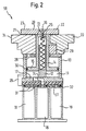
- Fig. 2
- ein Schnitt durch die Vorrichtung zum Spannen von Werkstücken in einer zweiten Ausführungsform ist; und
- Fig. 3
- eine Draufsicht auf die Vorrichtung zum Spannen von Werkstücken ist.
- Fig. 1.
- a section through the inventive device for clamping workpieces;
- Fig. 2
- a section through the device for clamping workpieces in a second embodiment; and
- Fig. 3
- is a plan view of the device for clamping workpieces.
In Fig. 1 ist eine erste Ausführungsform der Vorrichtung zum
Spannen von Werkstücken 50 dargestellt, wobei zwei
verschiedene Werkstücke 33, 34 gespannt sind.In Fig. 1 is a first embodiment of the device for
Clamping
Die Vorrichtung umfaßt ein Grundelement 10, das über eine
Bodenwand 17 auf der Aufstellfläche 32 auf dem Werkstückplatz
angebracht werden kann. Die Befestigung des Grundelements 10
auf dem Werkstückplatz einer Werkzeugmaschine zur spanenden
oder spanlosen Bearbeitung von Werkstücken, z.B. Bohren,
Fräsen, Sägen oder Kleben und Biegen, geschieht bei der
dargestellten Ausführungsform des Grundelements über eine
Reihe von Saugöffnungen an der Oberseite eines Balkens auf
dem Werkstückplatz einer Werkzeugmaschine, die mit den
Vakuumvorrichtungen 31 im Bodenbereich des Grundelements
wechselwirken. Die Vakuumzufuhr 19 zu den Saugöffnungen im
Werkstückplatz, die einem ersten Vakuumkreis entspricht, ist
schematisch dargestellt. Dieses Grundelement kann in einer
anderen (nicht dargestellten) Ausführungsform statt direkt
über Saugöffnungen mit Ventilen auf den Balken der
Werkzeugmaschine evakuierbar zu sein, auch über seitlich
angebrachte Schläuche evakuiert werden. Allerdings entsteht
dann durch die Schläuche eine gewisse Beeinträchtigung der
Zugänglichkeit zum Werkstück.The device comprises a
An das Grundelement 10 ist in der in Fig. 1 dargestellten
Ausführungsform eine Positionierhilfe 28 angebracht. Diese
Positionierhilfe dient dazu, das Grundelement auf dafür
vorgesehenem Balken des Werkstückplatzes einer
Werkzeugmaschine in X-, Y-Ebene ausrichten zu können. Dieser
Vorgang kann entweder von Hand vorgenommen werden oder unter
Zuhilfenahme von Robotern. Das Grundelement 10 wird mittels
der Justieranschläge 27 auf dem Werkstückplatz der
Werkzeugmaschine gegenüber der Waagerechten ausgerichtet.The
In dieses Grundelement 10, das in der Fachsprache mit
Saugspanner oder Blocksauger bezeichnet wird, ist eine
Kolbenanordnung 13 integriert. Die Kolbenanordnung 13 besteht
aus einer Kolbenstange 14 und einer Kolbenplatte 15. Die
Kolbenstange 14 ist durch eine Öffnung in der in Einbaulage
Oberseite des Grundelements geführt. Die Kolbenplatte 15 ist
so gestaltet, daß sie im wesentlichen der Geometrie der
Bodenfläche des Grundelements 10 entspricht und somit eine
Art Zwischenwand zwischen Bodenwand des Grundelements 10 und
oberer Wand des Grundelements 10 schafft. Um einen
evakuierbaren Hohlraum 11 zu bilden, ist an der Seitenfläche
der Kolbenplatte 15 umlaufend eine Dichteinrichtung 30
angebracht. Die Dichteinrichtung 30 kann beispielsweise eine
Gummidichtung, wie ein O-Ring, sein. Es kann
selbstverständlich auch jede andere in der Technik übliche
Dichtung verwendet werden, die gleichzeitig ein Gleiten der
Kolbenplatte 15 entlang der Seitenwand des Grundelements 10
ermöglicht.In this
Zur genaueren Führung der Kolbenstange 14 ist im Inneren des
Grundelements 10 eine Führung 12 für die Kolbenanordnung 13
vorgesehen. Das Anbringen einer Führung für die
Kolbeneinrichtung 13 im Inneren des Grundelements 10 bewirkt,
daß der Raum zwischen Grundelement 10 und Oberseite der
Kolbenstange 14 nicht durch zusätzliche Führungselemente
beeinträchtigt wird. Dadurch vereinfacht sich das Einspannen
des Werkstücks in die Vorrichtung und eine Zugänglichkeit zum
Werkstück wird nicht durch die Führungsvorrichtung
beschränkt.For more precise guidance of the
In der Führungsvorrichtung 12 für die Kolbeneinrichtung 13
ist eine Rückstellfeder 25 angebracht. Diese Rückstellfeder
25 wirkt so, daß die Kolbenanordnung 13 von der
Rückstellfeder in einer Lage gehalten wird, die dadurch
gekennzeichnet ist, daß der Abstand zwischen Oberseite der
Kolbeneinrichtung 13 und Oberseite des Grundelements 10
größer als ein zu bearbeitendes Werkstück 33, 34 ist.In the
An der Oberseite der Kolbenanordnung 13 ist mit einem
Befestigungselement 16, das beispielsweise eine herkömmliche
Schraube sein kann, eine Spannpratze 20 befestigt. Das
Befestigungselement 16 ist vorteilhafterweise so gestaltet,
daß die Spannpratze 20 in jeder beliebigen Winkelstellung
fixiert werden kann und somit äußerst flexibel hinsichtlich
des Spannens des Werkstücks ist. Um Werkstücke sicher spannen
zu können, besitzt die Spannpratze vorzugsweise an ihrer
Unterseite eine elastische Beschichtung 21. Diese elastische
Beschichtung dient dazu, ein Rutschen des Werkstücks 33, 34
weitgehend auszuschließen und zudem das Werkstück gegen
Beschädigungen durch die Spannpratze zu schützen.At the top of the
Die in Fig. 1 dargestellte Spannpratze ist asymmetrisch
ausgebildet und besitzt einen kürzeren Spannschenkel 22 und
einen längeren Spannschenkel 23. Diese Bauweise erhöht die
Flexibilität hinsichtlich der Konfiguration und Geometrie der
Werkstücke 33, 34.The clamping claw shown in Fig. 1 is asymmetrical
trained and has a
Um die Anlage der Werkstücke 33, 34 zu erleichtern, umfaßt
die Vorrichtung ferner einen oder mehrere Justieranschläge
für das Werkstück oder die Werkstücke. Dieser Justieranschlag
29 ist nicht fest mit dem Grundelement 10 oder der
Kolbeneinrichtung 13 verbunden. Das ermöglicht einen
einfachen Austausch des Justieranschlags 29 abhängig von der
Geometrie des Werkstücks 33.To facilitate the placement of the
Weiterhin ist in der Bodenwand des Grundelements 10 eine
Einrichtung zur Vakuumzufuhr 24 vorgesehen. In der in Fig. 1
dargestellten Ausführungsform der Erfindung ist diese
Vakuumzufuhr 24 mit einer aus einem Schlauch bestehenden
Vakuumleitung 18 verbunden, die wiederum die Verbindung zu
einem zweiten Vakuumkreis der Werkzeugmaschine herstellt.
Über diese kann der Hohlraum 11 evakuiert werden.Furthermore, there is a in the bottom wall of the
Weiterhin umfaßt das Grundelement 10 eine Belüftungsöffnung
26. Bei einer Kolbenbewegung in Einbaulage nach unten kann
durch die Belüftungsöffnung 26 Luft in den durch die
Oberseite der Kolbenplatte 15, die Seitenwände des
Grundelements 10 und die obere Wand des Grundelements 10
gebildeten Hohlraum einströmen und somit für einen
Druckausgleich bei der Kolbenbewegung sorgen.Furthermore, the
In Fig. 2 ist eine ähnliche Vorrichtung zum Spannen von
Werkstücken wie in Fig. 1 dargestellt. Die Vakuumzufuhr zu
dem durch Bodenwand und Seitenwände des Grundelements 10
sowie Kolbenplatte 15 definierten Hohlraum ist jedoch so
gestaltet, daß sie durch die Bodenwand des Grundelements 10
hindurch verläuft und an der Aufstellfläche 32 des
Grundelements 10 mit Saugöffnungen an der Oberseite eines
Balkens auf dem Werkstückplatz einer Werkzeugmaschine
wechselwirkt, und so die Verbindung zwischen Vakuumzuführung
18 und evakuierbarem Hohlraum 11 hergestellt wird. Dadurch
entfallen Schläuche auf dem Werkstücktisch komplett.In Fig. 2 is a similar device for tensioning
Workpieces as shown in Fig. 1. The vacuum supply too
through the bottom wall and side walls of the
In Fig. 3 ist eine Draufsicht auf eine Vorrichtung zum
Spannen von Werkstücken, wie sie in den Fig. 1 oder 2 gezeigt
ist, dargestellt. Die Spannpratze 20 ist in jeder beliebigen
Winkelstellung durch das Befestigungselement 16, etwa eine
Schraube, justierbar. Das ermöglicht eine große Flexibilität
bei der Einspannung eines Werkstücks.In Fig. 3 is a plan view of a device for
Clamping workpieces as shown in Fig. 1 or 2
is presented, layed out. The
Anhand von Fig. 1 sei im folgenden kurz die Wirkungsweise der
Vorrichtung zum Spannen von Werkstücken beschrieben. Der
Saugspanner, der im wesentlichen dem Grundelement 10
entspricht, wird auf einen dafür vorgesehenen Platz auf einem
Balken eines Werkstückplatzes einer Werkzeugmaschine gestellt
wird mit Hilfe der Justiereinrichtungen 27, 28 ausgerichtet.
Anschließend wird ein erster Vakuumkreis aktiviert, so daß
das Grundelement 10 durch die Vakuumräume 31 und die
Vakuumzuführung 19 auf dem Werkstückplatz der
Werkzeugmaschine fixiert wird. Die genaue Positionierung des
Grundelements 10 in der X-, Y-Ebene geschieht zuvor über die
Positionierhilfe 28.1, the mode of operation of the
Device for clamping workpieces described. The
Suction clamp, which is essentially the
In der Regel werden mehrere solche Grundelemente auf dem
Werkstückplatz einer Werkzeugmaschine aufgestellt.
Anschließend daran wird das oder werden die Werkstücke in den
durch die Rückstellfeder 25 offen gehaltenen Bereich zwischen
Spannpratze 20 und Oberseite des Grundelements 10 eingelegt,
gegebenenfalls unter Zuhilfenahme eines Justieranschlags 29.
Die Spannpratze 20 kann dabei durch Drehen in eine Lage
gebracht werden, die eine entsprechend der gewünschten
Bearbeitung zufriedenstelltende Zugänglichkeit zum Werkstück
ermöglicht.Usually there are several such basic elements on the
Workplace position of a machine tool set up.
Subsequently, this will be or the workpieces in the
by the
Durch Zuschalten des zweiten Vakuumkreises wird über eine
Vakuumzufuhr 18, 24 ein zweiter Vakuumkreis aktiviert, so daß
der durch die untere Wand des Grundelements, die Seitenwände
des Grundelements 10 und die Kolbenplatte 15 gebildete
Hohlraum evakuiert wird. Dies führt dazu, daß die
Kolbenanordnung 13 in Einbaulage nach unten bewegt wird,
gegen Verkanten oder Verdrehen geführt vom Führungselement
12. Dadurch wird das Werkstück oder werden die Werkstücke 33,
34 zwischen Spannpratze 20 und Oberseite des Grundelements 10
gespannt und können bearbeitet werden. Solange das Vakuum im
evakuierten Raum 11 sichergestellt ist, ist ein
unbeabsichtigtes Lösen des Werkstücks, das auch ein
leistenförmiges Werkstück sein kann, ausgeschlossen.By switching on the second vacuum circuit, a
Zum Lösen des Werkstücks wird das Vakuum im evakuierten
Hohlraum 11 über die Zufuhreinrichtungen 18, 24 deaktiviert,
die Federkraft der Rückstellfeder 25 kann somit die
Kolbeneinrichtung 13 sowie die Spannpratze 20 nach oben
drücken und das Werkstück kann aus der Vorrichtung entnommen
werden.To release the workpiece, the vacuum is evacuated
Der wesentliche Aspekt der erfindungsgemäßen Vorrichtung zum Spannen von Werkstücken liegt darin, daß auch leistenförmige Bauteile gespannt werden können, und trotzdem die Vorteile des Spannens von Werkstücken mittels Saugspannern erhalten bleiben, insbesondere die gute Zugänglichkeit zum Werkstück. Darüber hinaus sind keine ortsabhängigen Energiezuführleitungen, etwa für Druckluft oder Hydraulik, nötig, sondern die zum Spannen von plattenförmigen Werkstücken bereits vielfach eingesetzten Vakuumvorrichtungen können auch bei der Bearbeitung von leistenähnlichen Bauteilen verwendet werden. In einer bevorzugten Ausführungsform ist das System komplett schlauchlos und dadurch sehr flexibel. Die bei spanender Bearbeitung anfallenden Späne können sich zudem nicht in den Schläuchen zur Zufuhr an die Evakuiereinheiten verfangen. Schließlich bietet das System eine hohe Sicherheit hinsichtlich der Befestigung der Werkstücke, da eine Vakuumabfrage etwaige Störungen einfach und zuverlässig feststellen kann. Dies wiederum reduziert die Unfallgefahr.The essential aspect of the device according to the invention Clamping workpieces lies in the fact that also strip-shaped Components can be clamped, and still the advantages the clamping of workpieces with suction clamps remain, especially the good accessibility to the workpiece. In addition, there are no location dependent Energy supply lines, e.g. for compressed air or hydraulics, necessary, but that for clamping plate-shaped Workpieces already used vacuum devices can also be used when processing strip-like Components are used. In a preferred one The embodiment is completely tubeless and therefore very flexible. The machining resulting chips can also not be in the hoses Caught for delivery to the evacuation units. Finally the system offers a high level of security with regard to the Fastening of the workpieces, since a vacuum query is possible Can easily and reliably determine faults. This in turn reduces the risk of accidents.
Claims (21)
dadurch gekennzeichnet, dass
characterized in that
dadurch gekennzeichnet, dass
characterized in that
dadurch gekennzeichnet, dass
characterized in that
dadurch gekennzeichnet, dass
characterized in that
dadurch gekennzeichnet, dass
characterized in that
dadurch gekennzeichnet, dass
characterized in that
dadurch gekennzeichnet, dass
characterized in that
dadurch gekennzeichnet, dass
characterized in that
dadurch gekennzeichnet,
characterized,
dadurch gekennzeichnet, dass
characterized in that
dadurch gekennzeichnet,
characterized,
dadurch gekennzeichnet, dass
characterized in that
dadurch gekennzeichnet, dass
characterized in that
dadurch gekennzeichnet, dass
characterized in that
dadurch gekennzeichnet, dass
characterized in that
dadurch gekennzeichnet, dass
characterized in that
dadurch gekennzeichnet, dass
characterized in that
Applications Claiming Priority (2)
| Application Number | Priority Date | Filing Date | Title |
|---|---|---|---|
| DE19938851A DE19938851B4 (en) | 1999-08-17 | 1999-08-17 | Device for clamping workpieces |
| DE19938851 | 1999-08-17 |
Publications (3)
| Publication Number | Publication Date |
|---|---|
| EP1077112A2 true EP1077112A2 (en) | 2001-02-21 |
| EP1077112A3 EP1077112A3 (en) | 2002-08-14 |
| EP1077112B1 EP1077112B1 (en) | 2010-03-03 |
Family
ID=7918586
Family Applications (1)
| Application Number | Title | Priority Date | Filing Date |
|---|---|---|---|
| EP00114959A Expired - Lifetime EP1077112B1 (en) | 1999-08-17 | 2000-07-19 | Device for clamping workpieces |
Country Status (3)
| Country | Link |
|---|---|
| EP (1) | EP1077112B1 (en) |
| AT (1) | ATE459454T1 (en) |
| DE (2) | DE19938851B4 (en) |
Cited By (3)
| Publication number | Priority date | Publication date | Assignee | Title |
|---|---|---|---|---|
| WO2016071351A1 (en) * | 2014-11-03 | 2016-05-12 | Homag Holzbearbeitungssysteme Gmbh | Clamping device |
| CN112045791A (en) * | 2020-09-04 | 2020-12-08 | 安徽艾雅伦新材料科技有限公司 | Cutting machine for wood-plastic floor production and working method thereof |
| CN114536066A (en) * | 2022-04-08 | 2022-05-27 | 江苏安全技术职业学院 | Electric automatization rotatable drilling piece anchor clamps |
Families Citing this family (6)
| Publication number | Priority date | Publication date | Assignee | Title |
|---|---|---|---|---|
| DE102005020801A1 (en) * | 2005-04-28 | 2006-11-02 | Reich Spezialmaschinen Gmbh | Holding device for workpieces to be machined and vacuum clamping system with such a holding device |
| DE102007016457B4 (en) | 2007-03-30 | 2013-04-25 | J. Schmalz Gmbh | Pneumatically actuated fixing device |
| DE102009032703A1 (en) | 2009-07-09 | 2011-01-13 | Mtu Aero Engines Gmbh | Device and method for arranging a component on a component carrier |
| DE102011012739A1 (en) * | 2011-02-24 | 2012-08-30 | Michael Weinig Ag | Clamping device for workpieces made of wood, plastic and the like |
| DE202017102182U1 (en) * | 2017-04-11 | 2018-07-12 | Grünewald Treppenfertigung GmbH | Device for holding a workpiece by means of negative pressure on a processing table |
| DE102020132391A1 (en) | 2020-12-07 | 2022-06-09 | Ima Schelling Deutschland Gmbh | clamping device |
Citations (6)
| Publication number | Priority date | Publication date | Assignee | Title |
|---|---|---|---|---|
| DE1161519B (en) * | 1961-05-24 | 1964-01-16 | Erwin Lothar Holland Merten | Vacuum assembly device |
| US3476377A (en) * | 1967-10-19 | 1969-11-04 | Mattel Inc | Sheet clamping couple |
| US5312094A (en) * | 1993-01-21 | 1994-05-17 | Zera Robert D | Vacuum clamp |
| DE4404413C1 (en) * | 1994-02-11 | 1995-01-19 | Klessmann Ima Norte Maschfab | Vacuum clamping device |
| US5883522A (en) * | 1996-11-07 | 1999-03-16 | National Semiconductor Corporation | Apparatus and method for retaining a semiconductor wafer during testing |
| US5899445A (en) * | 1996-04-18 | 1999-05-04 | Kimble; Alvin J. | Locking ring vacuum clamping system with load/unload capabilities |
Family Cites Families (1)
| Publication number | Priority date | Publication date | Assignee | Title |
|---|---|---|---|---|
| FR2763877B1 (en) * | 1997-05-30 | 1999-08-27 | Itb | DEVICE FOR FIXING A FLAT PART BY AIR DEPRESSION OF THE VACUUM TABLE TYPE FOR A MACHINING CENTER |
-
1999
- 1999-08-17 DE DE19938851A patent/DE19938851B4/en not_active Expired - Fee Related
-
2000
- 2000-07-19 AT AT00114959T patent/ATE459454T1/en not_active IP Right Cessation
- 2000-07-19 EP EP00114959A patent/EP1077112B1/en not_active Expired - Lifetime
- 2000-07-19 DE DE50015876T patent/DE50015876D1/en not_active Expired - Lifetime
Patent Citations (6)
| Publication number | Priority date | Publication date | Assignee | Title |
|---|---|---|---|---|
| DE1161519B (en) * | 1961-05-24 | 1964-01-16 | Erwin Lothar Holland Merten | Vacuum assembly device |
| US3476377A (en) * | 1967-10-19 | 1969-11-04 | Mattel Inc | Sheet clamping couple |
| US5312094A (en) * | 1993-01-21 | 1994-05-17 | Zera Robert D | Vacuum clamp |
| DE4404413C1 (en) * | 1994-02-11 | 1995-01-19 | Klessmann Ima Norte Maschfab | Vacuum clamping device |
| US5899445A (en) * | 1996-04-18 | 1999-05-04 | Kimble; Alvin J. | Locking ring vacuum clamping system with load/unload capabilities |
| US5883522A (en) * | 1996-11-07 | 1999-03-16 | National Semiconductor Corporation | Apparatus and method for retaining a semiconductor wafer during testing |
Cited By (3)
| Publication number | Priority date | Publication date | Assignee | Title |
|---|---|---|---|---|
| WO2016071351A1 (en) * | 2014-11-03 | 2016-05-12 | Homag Holzbearbeitungssysteme Gmbh | Clamping device |
| CN112045791A (en) * | 2020-09-04 | 2020-12-08 | 安徽艾雅伦新材料科技有限公司 | Cutting machine for wood-plastic floor production and working method thereof |
| CN114536066A (en) * | 2022-04-08 | 2022-05-27 | 江苏安全技术职业学院 | Electric automatization rotatable drilling piece anchor clamps |
Also Published As
| Publication number | Publication date |
|---|---|
| EP1077112B1 (en) | 2010-03-03 |
| EP1077112A3 (en) | 2002-08-14 |
| DE19938851B4 (en) | 2005-04-07 |
| DE19938851A1 (en) | 2001-03-08 |
| ATE459454T1 (en) | 2010-03-15 |
| DE50015876D1 (en) | 2010-04-15 |
Similar Documents
| Publication | Publication Date | Title |
|---|---|---|
| EP1600254B1 (en) | Conveying unit for machine for working workpieces and method for machining such workpieces | |
| EP3703912B1 (en) | Supplementary support assembly for a workpiece support assembly | |
| DE102007022200B4 (en) | Machine tool with numerical control | |
| EP1077112B1 (en) | Device for clamping workpieces | |
| AT519407B1 (en) | Processing plant for plates and the like and realized with this plant production line | |
| EP1997582A1 (en) | Method for calibrating a tooling fixture | |
| EP1163973B1 (en) | Table for a machine tool | |
| EP0121134B1 (en) | Multipurpose clamping tool for processing workpieces, in particular wooden ones | |
| EP2185330A1 (en) | Molding machine and drilling unit for use in a molding machine | |
| DE4417306C1 (en) | Working fixture for milling machine handling wooden workpieces | |
| EP0292864A1 (en) | Wood-working machine | |
| DE4207353A1 (en) | TOOL HOLDER FOR A CUTTING TOOL | |
| EP1990135B1 (en) | Work piece clamping device | |
| DE102019112337A1 (en) | Tool holding device | |
| EP2185331A1 (en) | Device for working workpieces made of wood, plastic and the like and method for working said workpieces | |
| DE2722219C3 (en) | Machine tool that can be assembled from assemblies | |
| WO2019179789A1 (en) | Milling adapter for a workbench | |
| DE3402101C2 (en) | ||
| DE202012002940U1 (en) | jig | |
| DE102005018646B3 (en) | Milling machine has chip suction housing which is adjustable around its axis at milling position and stopper is arranged which is freely movable in axial direction of work piece receiver | |
| DE202023105596U1 (en) | vice | |
| DE19941911A1 (en) | Multi-function machine tool for finishing workpieces with C-shaped cross-section has machine bed forming workpiece support with row of cross slides with tension devices having bearing surface and clamping devices for workpiece | |
| DE3419154C2 (en) | ||
| DE1004363B (en) | Additional device for electrical hand machine tools with a support table for guiding the workpiece to be processed | |
| EP4194165A1 (en) | Machine tool for machining a workpiece made of wood |
Legal Events
| Date | Code | Title | Description |
|---|---|---|---|
| PUAI | Public reference made under article 153(3) epc to a published international application that has entered the european phase |
Free format text: ORIGINAL CODE: 0009012 |
|
| AK | Designated contracting states |
Kind code of ref document: A2 Designated state(s): AT BE CH CY DE DK ES FI FR GB GR IE IT LI LU MC NL PT SE |
|
| AX | Request for extension of the european patent |
Free format text: AL;LT;LV;MK;RO;SI |
|
| PUAL | Search report despatched |
Free format text: ORIGINAL CODE: 0009013 |
|
| AK | Designated contracting states |
Kind code of ref document: A3 Designated state(s): AT BE CH CY DE DK ES FI FR GB GR IE IT LI LU MC NL PT SE |
|
| AX | Request for extension of the european patent |
Free format text: AL;LT;LV;MK;RO;SI |
|
| 17P | Request for examination filed |
Effective date: 20030213 |
|
| AKX | Designation fees paid |
Designated state(s): AT BE CH CY DE DK ES FI FR GB GR IE IT LI LU MC NL PT SE |
|
| 17Q | First examination report despatched |
Effective date: 20071213 |
|
| GRAP | Despatch of communication of intention to grant a patent |
Free format text: ORIGINAL CODE: EPIDOSNIGR1 |
|
| GRAS | Grant fee paid |
Free format text: ORIGINAL CODE: EPIDOSNIGR3 |
|
| GRAA | (expected) grant |
Free format text: ORIGINAL CODE: 0009210 |
|
| AK | Designated contracting states |
Kind code of ref document: B1 Designated state(s): AT BE CH CY DE DK ES FI FR GB GR IE IT LI LU MC NL PT SE |
|
| REG | Reference to a national code |
Ref country code: GB Ref legal event code: FG4D Free format text: NOT ENGLISH |
|
| REG | Reference to a national code |
Ref country code: CH Ref legal event code: EP |
|
| REG | Reference to a national code |
Ref country code: IE Ref legal event code: FG4D |
|
| REF | Corresponds to: |
Ref document number: 50015876 Country of ref document: DE Date of ref document: 20100415 Kind code of ref document: P |
|
| REG | Reference to a national code |
Ref country code: NL Ref legal event code: VDEP Effective date: 20100303 Ref country code: CH Ref legal event code: NV Representative=s name: NOVAGRAAF INTERNATIONAL SA |
|
| PG25 | Lapsed in a contracting state [announced via postgrant information from national office to epo] |
Ref country code: FI Free format text: LAPSE BECAUSE OF FAILURE TO SUBMIT A TRANSLATION OF THE DESCRIPTION OR TO PAY THE FEE WITHIN THE PRESCRIBED TIME-LIMIT Effective date: 20100303 |
|
| REG | Reference to a national code |
Ref country code: IE Ref legal event code: FD4D |
|
| PG25 | Lapsed in a contracting state [announced via postgrant information from national office to epo] |
Ref country code: SE Free format text: LAPSE BECAUSE OF FAILURE TO SUBMIT A TRANSLATION OF THE DESCRIPTION OR TO PAY THE FEE WITHIN THE PRESCRIBED TIME-LIMIT Effective date: 20100303 Ref country code: IE Free format text: LAPSE BECAUSE OF FAILURE TO SUBMIT A TRANSLATION OF THE DESCRIPTION OR TO PAY THE FEE WITHIN THE PRESCRIBED TIME-LIMIT Effective date: 20100303 Ref country code: NL Free format text: LAPSE BECAUSE OF FAILURE TO SUBMIT A TRANSLATION OF THE DESCRIPTION OR TO PAY THE FEE WITHIN THE PRESCRIBED TIME-LIMIT Effective date: 20100303 Ref country code: GR Free format text: LAPSE BECAUSE OF FAILURE TO SUBMIT A TRANSLATION OF THE DESCRIPTION OR TO PAY THE FEE WITHIN THE PRESCRIBED TIME-LIMIT Effective date: 20100604 Ref country code: ES Free format text: LAPSE BECAUSE OF FAILURE TO SUBMIT A TRANSLATION OF THE DESCRIPTION OR TO PAY THE FEE WITHIN THE PRESCRIBED TIME-LIMIT Effective date: 20100614 Ref country code: CY Free format text: LAPSE BECAUSE OF FAILURE TO SUBMIT A TRANSLATION OF THE DESCRIPTION OR TO PAY THE FEE WITHIN THE PRESCRIBED TIME-LIMIT Effective date: 20100303 |
|
| PLBE | No opposition filed within time limit |
Free format text: ORIGINAL CODE: 0009261 |
|
| STAA | Information on the status of an ep patent application or granted ep patent |
Free format text: STATUS: NO OPPOSITION FILED WITHIN TIME LIMIT |
|
| BERE | Be: lapsed |
Owner name: GUSTAV WEEKE MASCHINENBAU G.M.B.H. Effective date: 20100731 |
|
| PG25 | Lapsed in a contracting state [announced via postgrant information from national office to epo] |
Ref country code: DK Free format text: LAPSE BECAUSE OF FAILURE TO SUBMIT A TRANSLATION OF THE DESCRIPTION OR TO PAY THE FEE WITHIN THE PRESCRIBED TIME-LIMIT Effective date: 20100303 Ref country code: PT Free format text: LAPSE BECAUSE OF FAILURE TO SUBMIT A TRANSLATION OF THE DESCRIPTION OR TO PAY THE FEE WITHIN THE PRESCRIBED TIME-LIMIT Effective date: 20100705 |
|
| 26N | No opposition filed |
Effective date: 20101206 |
|
| PG25 | Lapsed in a contracting state [announced via postgrant information from national office to epo] |
Ref country code: MC Free format text: LAPSE BECAUSE OF NON-PAYMENT OF DUE FEES Effective date: 20100731 |
|
| REG | Reference to a national code |
Ref country code: CH Ref legal event code: PL |
|
| GBPC | Gb: european patent ceased through non-payment of renewal fee |
Effective date: 20100719 |
|
| PG25 | Lapsed in a contracting state [announced via postgrant information from national office to epo] |
Ref country code: IT Free format text: LAPSE BECAUSE OF FAILURE TO SUBMIT A TRANSLATION OF THE DESCRIPTION OR TO PAY THE FEE WITHIN THE PRESCRIBED TIME-LIMIT Effective date: 20100303 |
|
| REG | Reference to a national code |
Ref country code: FR Ref legal event code: ST Effective date: 20110331 |
|
| PG25 | Lapsed in a contracting state [announced via postgrant information from national office to epo] |
Ref country code: CH Free format text: LAPSE BECAUSE OF NON-PAYMENT OF DUE FEES Effective date: 20100731 Ref country code: LI Free format text: LAPSE BECAUSE OF NON-PAYMENT OF DUE FEES Effective date: 20100731 |
|
| PG25 | Lapsed in a contracting state [announced via postgrant information from national office to epo] |
Ref country code: FR Free format text: LAPSE BECAUSE OF NON-PAYMENT OF DUE FEES Effective date: 20100802 |
|
| PG25 | Lapsed in a contracting state [announced via postgrant information from national office to epo] |
Ref country code: BE Free format text: LAPSE BECAUSE OF NON-PAYMENT OF DUE FEES Effective date: 20100731 |
|
| PG25 | Lapsed in a contracting state [announced via postgrant information from national office to epo] |
Ref country code: GB Free format text: LAPSE BECAUSE OF NON-PAYMENT OF DUE FEES Effective date: 20100719 |
|
| PG25 | Lapsed in a contracting state [announced via postgrant information from national office to epo] |
Ref country code: AT Free format text: LAPSE BECAUSE OF NON-PAYMENT OF DUE FEES Effective date: 20100719 |
|
| PGFP | Annual fee paid to national office [announced via postgrant information from national office to epo] |
Ref country code: DE Payment date: 20110728 Year of fee payment: 12 |
|
| PG25 | Lapsed in a contracting state [announced via postgrant information from national office to epo] |
Ref country code: LU Free format text: LAPSE BECAUSE OF NON-PAYMENT OF DUE FEES Effective date: 20100719 |
|
| PG25 | Lapsed in a contracting state [announced via postgrant information from national office to epo] |
Ref country code: DE Free format text: LAPSE BECAUSE OF NON-PAYMENT OF DUE FEES Effective date: 20130201 |
|
| REG | Reference to a national code |
Ref country code: DE Ref legal event code: R119 Ref document number: 50015876 Country of ref document: DE Effective date: 20130201 |