EP1077433A1 - Data aquisition and transfer - Google Patents
Data aquisition and transfer Download PDFInfo
- Publication number
- EP1077433A1 EP1077433A1 EP00307044A EP00307044A EP1077433A1 EP 1077433 A1 EP1077433 A1 EP 1077433A1 EP 00307044 A EP00307044 A EP 00307044A EP 00307044 A EP00307044 A EP 00307044A EP 1077433 A1 EP1077433 A1 EP 1077433A1
- Authority
- EP
- European Patent Office
- Prior art keywords
- vehicle
- data
- service
- information
- source
- Prior art date
- Legal status (The legal status is an assumption and is not a legal conclusion. Google has not performed a legal analysis and makes no representation as to the accuracy of the status listed.)
- Withdrawn
Links
Images


Classifications
-
- G—PHYSICS
- G07—CHECKING-DEVICES
- G07C—TIME OR ATTENDANCE REGISTERS; REGISTERING OR INDICATING THE WORKING OF MACHINES; GENERATING RANDOM NUMBERS; VOTING OR LOTTERY APPARATUS; ARRANGEMENTS, SYSTEMS OR APPARATUS FOR CHECKING NOT PROVIDED FOR ELSEWHERE
- G07C5/00—Registering or indicating the working of vehicles
- G07C5/008—Registering or indicating the working of vehicles communicating information to a remotely located station
Definitions
- the present invention relates to a data system and to a dispenser system.
- An embodiment of the present invention relates to a vehicle information system.
- Another embodiment relates to a system for acquiring and transferring information from a vehicle.
- U.S. Patent No. 5,058,044 (the '044 patent) to Stewart et al. describes a system that includes a processing system on-board a vehicle for gathering data related to the operational history of the vehicle and transferring the data to a stationery processing system, such as for a mechanic regarding needed repairs and/or automated commercial transactions such as the billing of vehicle rentals or of repair work.
- the on-board system includes a processor for collecting data from sensors associated with selected operations systems of the vehicle (e.g., lights, drive train, tires, and fluid levels).
- the processor may continually update its condition (e.g., mileage and gas level) in a storage area or it may only store information when service is required (e.g., lights and drive train).
- the on-board system is interrogated for its stored information.
- the interrogation is executed by an annunciator system which first detects the physical presence of the vehicle and then transmits an RF interrogation signal to a receiver on-board the vehicle that is coupled to the on-board processor. If the interrogation signal is recognized by the on-board processor, a vehicle identification code along with the stored information is convened to an RF signal and transmitted from the vehicle.
- the vehicle may have to be substantially modified to accommodate the system of the '044 patent. Further, because the vehicle includes both a receiver and a transmitter, the complexity and cost of the '044 system is undesirably increased.
- U.S. Patent No. 5,974,368 (the '368 patent) to Schepps et al describes a remote vehicle data interface system in which vehicle-related data is transmitted by a low-cost RF tag system in the vehicle to an RF interrogator without the need for each to have both an RF transmitter and an RF receiver.
- the system of the '368 patent connects to a vehicle data bus to receive the vehicle-related data without need for substantial modification of the vehicle.
- a data system of one aspect of the present invention comprises at least one source of vehicle-related data, at least one source of external data not related to vehicle data, and a transmitter coupled to each of the sources for receiving the vehicle-related data and the external data therefrom, the transmitter transmitting the vehicle-related data and the external data.
- external data include a source of heading information, such as an electronic compass, and a service dispenser, such as a fuel dispenser.
- utilization systems include controls for traffic signals and service facilities.
- a data system for a vehicle comprises, in addition to sources of vehicle-related data and of external data not related to vehicle data, and a transmitter on the vehicle, an interrogator receiving the vehicle-related data and the external data from the transmitter, and a utilization system coupled to said interrogator and responsive to at least the external data.
- a vehicle service dispenser system comprises a service dispenser external to a vehicle including a source of service dispenser information and a transducer for transmitting and/or receiving service information including the service dispenser information.
- Coupling means couples the vehicle to the service dispenser for receiving service and for coupling service information.
- a sensor on the vehicle is adapted to receive and/or transmit service information with the service dispenser external to the vehicle via the coupling means, and means is coupled to at least one of the sensor and the transducer for utilizing the service information.
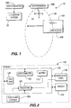
- FIGURE 1 shows a vehicle information system 10 including a tag system 120 mounted in a vehicle 100.
- the tag system 120 transmits vehicle-related data acquired from vehicle 100 and from external devices (shown in FIGURES 2, 3, 5 and 6) to interrogator 300.
- Vehicle information system 10 utilizes a data bus 110 (shown in FIGURES 2 and 5) in vehicle 100, which data bus 110 is typically part of vehicle 100 for control and monitoring of the operation thereof, with low-cost RF communications between tag system 120 and interrogator 300 to remotely access the vehicle-related data and data from the external device when the vehicle 100 is in a designated area 20.
- Interrogator 300 provides the data from vehicle 100 acquired through tag system 120 to host computer 320.
- the vehicle-related data includes, for example, temperature, fluid levels, oil pressure, odometer, and other data related to the vehicle 100.
- Data from an external device includes, for example, heading data from an electronic compass, pump data from a fueling pump and other data as may be acquired or generated by a device external to tag system 120 of vehicle 100.
- Tag system 120 may also be used to read the status of emissions-related and safety-related parameters without having to directly connect any equipment to the vehicle.
- the tag system 120 includes an RF transmitter 210 (shown in FIGURES 3 and 6) for transmitting the vehicle-related data and the data from an external device 500 and the interrogator 300 includes an RF receiver 305 (shown in FIGURES 3 and 6) for receiving the vehicle-related data and the data from an external device 500.
- the complexity and cost of the tag system 120 and the interrogator 300 are reduced because neither includes circuitry and software to both transmit and receive data.
- tag system 120 and interrogator 300 may each include both a transmitter and a receiver for each both transmitting and receiving data.
- Tag system 120 only monitors data transmitted on vehicle data bus 110 and, as a result, the control and operation of data bus 110 does not have to be modified to accommodate the tag system 120. In this way, the tag system 120 may be integrated into the vehicle 100 with minimal modification to the vehicle 100. Thus, the vehicle information system 10 is more likely to be accepted and incorporated into vehicles 100 by vehicle manufacturers. In an alternative embodiment, the tag system 120 may both receive data from data bus 110 and transmit data on data bus 110.
- Vehicle information system 10 may be utilized in a variety of environments to remotely monitor vehicles.
- the vehicle information system 10 may be used to determine the speed and/or direction of travel of a vehicle.
- the tag system 120 repeatedly transmits the speed and/or direction of travel along with the vehicle identification data of vehicle 100 as it travels along a road.
- An interrogator 300 positioned adjacent to the road or at an intersection receives the transmitted data for subsequent processing.
- vehicle information system 10 may be used to monitor cars and/or trucks as they leave and/or arrive at a vehicle rental facility, vehicle service facility, central terminal or other facility.
- interrogator 300 may be located at access points, e.g., entrance/ingress and exit/egress points, to the facility to acquire data transmitted from tag systems 120 coupled to the car and/or truck.
- the host computer 320 or host system 320 utilizes the data acquired from the interrogator 300 to determine which cars and/or trucks have entered and exited the facility or are located at particular locations or stations within the facility.
- FIGURE 1 shows a vehicle information system 10 including a tag system 120 mounted in an area of vehicle 100 not visible to the casual observer and not completely enclosed by metallic surfaces, for example, behind the dashboard in the passenger compartment, behind bumpers, or behind non-metallic body parts, or on the vehicle underside.
- Tag system 120 located in vehicle 100 intermittently transmits data, preferably in the form of message data packets 400 (shown in FIGURE 4).
- Interrogator 300 receives transmitted data message packets 400 when vehicle 100 is in the designated area 20 of interrogator 300.
- the size of designated area 20 may be adjusted by increasing or decreasing either the strength of the signal transmitted from tag system 120 or the sensitivity of the RF receiver 305 (shown in FIGURES 3 and 6) in interrogator 300, or by installing repeaters.
- Interrogator 300 has an antenna (not shown) that is oriented to define the orientation of area 20 with respect to interrogator 300 so that one or more message packets 400 transmitted from tag system 120 may be received by interrogator 300 when the vehicle 100 is in designated area 20.
- Interrogator 300 may be a hand held device or be permanently mounted.
- Interrogator 300 communicates with host computer 320 via a communication link, such as an RF link, electrical wires or cables, an optical fiber, or other convenient communication apparatus.
- Host computer 320 utilizes the data transmitted by tag system 120 to signal and/or control a utilization device or system 30.
- the utilizations of system 10 include controlling traffic signals to give preference to emergency vehicles, tracking the fueling or other service device which a particular vehicle is using, monitoring and/or controlling vehicles in a truck depot or auto rental facility, and the like.
- Host computer 320 determines whether the vehicle 100 "matches" predetermined criteria, for example, for purposes of setting traffic signals or authorizing vehicle fueling, based on the data transmitted from tag system 120 and information stored in host computer 320. Vehicle 100 matches if the stored data and the vehicle identification data are the same, such as by comparison to a stored look-up table. If there is a match, host computer 320 provides a signal to utilization system 30 to set the traffic signals or to allow vehicle 100 to receive fuel, as the case may be. If there is not a match, no action is taken or an attendant or supervisor may be alerted to investigate or otherwise take appropriate action.
- predetermined criteria for example, for purposes of setting traffic signals or authorizing vehicle fueling
- utilization system 30 is the traffic signal and controller which turns the signal "green” for the emergency vehicle and "red” for all other roads at the intersection.
- Interrogators 300 for such systems typically include antennas facing in particular directions, e.g., north, east, south and west, as indicated by compass indicia 22.
- area 20 might represent the reception pattern of a receiver connected to a south-facing antenna.
- microwave frequency and other RF communications are reflected by, buildings and other fixed and/or mobile objects, and so may appear to come from a direction other than the true direction. This can occur, for example, due to multiple reflected signals arriving out of phase at an intended receiver and in-phase at an unintended receiver.
- the RF signal from a vehicle approaching the intersection from a particular direction e.g., south
- an external device 500 is an electronic compass that determines the direction of travel (or heading, as in compass heading) of the emergency vehicle and provides that information to tag system 120 which transmits the heading information.
- Interrogator 300 receives the signal from tag system 300 including the heading information and communicates same to host computer 320 which utilizes the heading information to determine which state the traffic signal 30 should be put into to give priority to the direction from which the emergency vehicle is approaching.
- utilization device 30 might be a computer utilized for authorizing service, such as fueling, or for billing, inventory control or other function. Such arrangement might be utilized with commercial as well as privately-owned vehicles, for example, in a car rental facility, a truck depot, or a gas station.
- interrogator 300 detects its presence from its transmitted signal and signals same to host computer 320 which authorizes the dispensing of fuel or other service based on an appropriate approval protocol.
- dispenser identification information is coupled to vehicle 100 through the fueling hose of the pump being placed in a fuel filler opening in the vehicle. While such information coupling could be by electrical signals transmitted through wires in the fueling hose to contacts in the vehicle filler pipe, the danger of fire or explosion renders such approaches undesirable.
- Couplings in the vehicle other than contacts could include a pair of induction coils, one in nozzle 616 and the other in filler pipe 132 surrounding nozzle 616 when nozzle 616 is inserted in filler pipe 132, but that still requires electrical wires in fuel hose 614.
- a transmitting acoustic transducer in the fueling pump transmits the pump identification information acoustically through the fueling hose and/or the fuel therein to a sensor in the vehicle that includes a receiving acoustic transducer.
- acoustic transmission system is inherently safe because the acoustic transducers and signal pose no danger of fuel ignition, either at the transmitter in the fuel dispenser or at the receiver in the vehicle, and there are no electrical wires in the fuel hose or in other fuel passages.
- Such acoustic system also avoids the reliability issues where electrical wires are embedded in a flexible hose and must pass through or around swivels, couplings and other plumbing components.
- FIGURES 2, 3 and 4 An embodiment that inserts heading information as external data into the RF tag system 120 of an emergency vehicle 100, as for giving priority to such vehicle, is described in relation to FIGURES 2, 3 and 4. It is noted that while a wide variety of different RF tag systems and interrogators could be employed in embodiments of the present invention, the tag system and interrogator described in U.S. Patent No. 5,974,386, are thought to be well suited and the descriptions herein are based upon such system.
- vehicle 100 includes vehicle data bus 110 that is used to transmit data between various vehicle components, such as fuel tank system 130, instrument panel 140, and other vehicle modules 150, and vehicle computer 160.
- Module 150 is, for example, an interface with other vehicle components of vehicle 100, such as the engine (not shown).
- Vehicle computer 160 may be, for example, the body or engine computer in the vehicle 100.
- Data is provided to and retrieved from data bus 110 (as indicated by double-ended arrows) in accordance with a data standard, for example, a vehicle data bus standard such as the Society of Automotive Engineers (SAE) J1850 standard or the Controller Area Network (CAN) standard.
- SAE J1850 standard defines an electrical and data protocol for transmitting and receiving data via data bus 110 between and/or among the components coupled to data bus 110, such as fuel tank system 130, instrument panel 140, module 150, and vehicle computer 160.
- Data bus 110 and the vehicle components coupled thereto are designed to ensure the reliable transmission of vehicle data, and the addition of other components that transmit data on data bus 110 may require modification of the operation of the vehicle components or substantial modification of data bus 110, or both, to ensure reliable data transmission. Thus it may not be advantageous to provide additional components that transmit data via data bus 110.
- Tag system 120 avoids these problems because it only monitors the data (as indicated by a single-ended arrow from data bus 110) that is transmitted by the vehicle components on data bus 110, and may be coupled to data bus 110 by, for example, crimping a connector on the wire or wires forming data bus 110.
- Data bus 110 may be, for example, as simple as a single wire loop. Because neither the vehicle components nor data bus 110 need be modified, tag system 120 may be integrated with minimal modification of the vehicle 100, and so vehicle manufacturers may be more willing to incorporate tag system 120 into vehicle 100. As a result, the installation costs of tag system 120 are minimized. Alternatively, tag system 120 may transmit data via data bus 110.
- an external data source provides external data unrelated to vehicle data to tag system 120.
- An external data source is typically an external device, such as electronic compass 500.
- Electronic compass 500 is preferably a low-cost device that is mounted to vehicle 100 in a predetermined orientation so as to determine the vehicle's heading.
- One suitable such electronic compass is the model Vector 2X available from Precision Navigation, located in Santa Rosa, California.
- Electronic compass 500 preferably generates a serial data stream that contains calibrated heading information for vehicle 100. While an electronic compass is preferred because of its small size, low operating power and low cost, other external devices, such as a gyroscope, a magnetic compass, a GPS receiver and the like, could also be utilized to provide the same or similar heading information.
- Tag system 120 is powered by vehicle battery 170 and may also transmit battery voltage information.
- tag system 120 includes processor 205 that is coupled to receive data from interface 200, to control and receive data from A/D converter 215, and provide data to RF transmitter 210 for transmission.
- Interface 200 is coupled to receive external data from external device, such as heading data from electronic compass 500 and to couple such data to processor 205.
- interface 200 is, for example, compliant with the SAE J1850 standard to provide an interface between tag system 120 and vehicle data bus 110 to only retrieve data from bus 110.
- Data that is transmitted on data bus 110 by the vehicle components coupled thereto typically includes component identification data and parametric data related to the vehicle component and/or its operation, which data is often contained in one or more data packets.
- interface 200 may also provide data to data bus 110.
- the data acquired from electronic compass 500 and from data bus 110 is provided to processor 205 which is, for example, a microprocessor or microcontroller.
- Interface 200 and processor 205 may be separate components or may be combined as a single component.
- One such combined component is integrated circuit part number MC68HC05V7 available from Motorola, Inc. located in Scottsdale, Arizona, which circuit is compatible, for example, with General Motors automobiles compliant with the SAE J1850 standard.
- Operation of processor 205 is known, for example, as described in U.S. Patent No. 5,974,368, and includes providing data to RF transmitter 210 for modulation and transmission.
- Processor 205 may also receive data from analog-to-digital (A/D) converter 215 which is coupled directly to a component that produces analog data, such as an analog data output 502 of electronic compass 500 (data path indicated by dashed arrow), or to an analog component of vehicle 100 such as a fuel-level sensing potentiometer or a temperature-sensing resistance.
- processor 205 may receive digital data directly from digital components, such as a digital data output 504 of electronic compass 500 (data path indicated by dashed arrow), or from a digital component in vehicle 100, i.e. data not requiring conversion by AID converter 215.
- processor 205 may receive digital data at a data bus input 206 from data bus 110 via interface 200, at an "analog" input 207 from an analog source converted to digital format by AID converter 215, and at a digital input 208 from a source of digital data in suitable format.
- Processor 205 produces a message data packet 400, such as that shown in FIGURE 4, and controls and modulates RF transmitter 210 to transmit 225 message packet 400, such as by turning transmitter 210 on and off, as is known.
- RF transmitter 210 is, for example, an AM surface acoustic wave (SAW) transmitter.
- SAW surface acoustic wave
- the message packet 400 transmitted by tag system 120 via RF link 225 is received by interrogator 300 which includes an RF receiver 305 that receives transmitted message packet 400.
- the received message packet 400 from receiver 305 is provided to demodulator 310 which demodulates received message packet 400 and couples the demodulated data to processor 315.
- Processor 315 processes and converts the received message packet data to a form suitable for host computer 320.
- RF link 225 between tag system 120 and interrogator 300 may be implemented using either "active" or “semi-active" transmission technology.
- battery 170 powers all of tag system 120 continually to produce continuous, or at least periodic, transmissions.
- battery 170 powers all of tag system 120 except for transmitter 210, and message packets 400 are transmitted between transmitter 210 and interrogator 300 via "passive backscatter.”
- passive backscatter a continuous wave is transmitted by interrogator 300, which is passively modulated and reflected back to interrogator 300 by tag system 120, as is known.
- FIGURE 4 A format for a message packet or data packet 400 containing several different types of data is shown in FIGURE 4.
- Message packet 400 includes a data type field 405 that indicates what type of data is contained in the packet and a sequence data field 410 that indicates whether the message packet 400 is a single message packet or one of a sequence of related message packets. In the latter case, sequence data field 410 indicates the position of each message packet 400 in the sequence of related message packets.
- Related message packets 400 may be utilized to reduce the size of each message packet, thereby to reduce the likelihood of data packet transmission collisions and interference among transmissions from a number of different tag systems 120.
- Data packet 400 includes, for example, vehicle identification data (VID) field 415, such as a vehicle identification number (VIN), that uniquely identifies vehicle 100 so that interrogator 300 and/or host computer 320 can associate each message packet with other message packets from the same vehicle.
- VIN vehicle identification number
- the message packet 400 may also include vehicle-related data fields such as fuel data field 420 indicating the fuel level in the fuel tank and odometer data field 425 indicating the odometer reading.
- Extra data field 430 is contained in message packet 400 for providing data from the external data source, such as from electronic compass 500, to interrogator 300 and host computer 320 via tag system 120.
- Message packet 400 also includes an error correction code 435, which is, for example, a cyclic redundancy code (CRC).
- CRC cyclic redundancy code
- FIGURE 5 is a schematic block diagram of a vehicle 100 including a tag system 120 and an external device 510 for identifying a dispenser according to an embodiment of the present invention.
- Vehicle 100 includes vehicle data bus 110 that is used to transmit data between various vehicle components, such as fuel tank system 130, instrument panel 140, other vehicle modules 150, and vehicle computer 160, and data is provided to and retrieved from data bus 110 (as indicated by double-ended arrows) in accordance with a data standard, all as described above in relation to FIGURE 2.
- Dispenser 600 includes a fuel pump 610 that pumps fuel through outlet pipe 612 and hose 614 to fuel nozzle 616, as is conventional. Actuating a valve in nozzle 616 causes fuel to flow from nozzle 616 into fuel filler pipe 132 of vehicle 100 and thence into fuel tank 130, as is conventional. During fueling, fuel is present in outlet pipe 612, hose 614 and filler pipe 132.
- fuel dispenser 600 represents a service dispenser and filler pipe 132 represents a service receiver on vehicle 100.
- external data 510 provides external data unrelated to vehicle data, such as identification data or other data relating to fuel dispenser 600 or other service facility, to tag system 120.
- External data source 510 is, for example, a source of signals relating to such service facility or service device, such as the fuel dispenser 600 that is used to fuel vehicle 100.
- Dispenser 600 includes a source 620 of pump identification information, for example, a uniquely coded digital word contained in an electronic memory such as a read-only-memory or a set of switches.
- Tone encoder 630 receives the pump-identifying digital word and encodes the pump identification as a sequence of tones, for example, as a sequence of audio frequency tones. In addition, encoder 630 may modulate the sequence of tones on a carrier signal, thereby producing a uniquely-coded audio-frequency electrical signal containing the pump identifying information.
- the coded electrical signal is provided to transmitting acoustic transducer 640 which is coupled 642 to outlet pipe 612 or to another fuel passage of dispenser 600 to transmit into the fuel therein an audio-frequency acoustic signal containing the pump information.
- the acoustic signal propagates through the fuel, i.e. through the column of fuel in outlet pipe 612, hose 614 and nozzle 616, to fuel filler pipe 132 of vehicle 100.
- External device 510 includes receiving acoustic transducer 520 that is coupled 512 to vehicle fuel filler pipe 132 to receive the acoustic signal, i.e. the coded audio tones, from the fuel therein.
- Device 510 includes a sensor 520 that converts the sequence of audio tones to an electrical tone signal and a tone decoder 630 that decodes the sequence of electrical tones to a digital electronic signal, such as a serial digital word, that is applied to tag system 120.
- Tag system 120 transmits the serial digital word representing the pump identification information to interrogator 300.
- FIGURE 6 is a schematic block diagram of a portion of system 10 illustrating tag system 120, interrogator 300 and external device 510 for identifying dispenser 600 according to an embodiment of the present invention.
- Tag system 120 includes processor 205 that is coupled to receive data from interface 200, to control and receive data from A/D converter 215, and provide data to RF transmitter 210 for transmission, all as described above in relation to FIGURE 3.
- Interface 200 is coupled to receive external data from external device 510, such as pump identification data from dispenser 600 in the form of a digital word produced by sensor/tone decoder 510, and to couple such data to processor 205.
- sensor/tone decoder 510 may produce at an output 514 a digital word representative of dispenser 600 identification in a form compatible with a digital input to processor 205 an apply such digital word directly thereto.
- the message packet 400 transmitted by tag system 120 to interrogator 300 is processed by host computer 320 to relate the vehicle identification data and pump identification data from tag system 120, such as for confirming authorization of the sale, billing the correct customer, maintaining fueling and/or inventory records, and the like. It is noted that if nozzle 616 is removed from filler pipe 132 of vehicle 100, the pump identification information in the data packets 400 transmitted by tag system 120 will be interrupted, such interruption can be utilized to interrupt or stop the pumping of fuel by dispenser 600, thereby preventing fueling to be resumed in another vehicle (unauthorized fueling or theft) and/or limiting spillage and the fire hazard and potential environmental damage that could result.
- Acoustic transducers for transmitting acoustic signals into a liquid and for sensing acoustic signals from a liquid are widely available and are utilized in many commercial devices, such as "sonar" fish finders and depth gauges for baits, and for ultra-sound medical devices and the like. Such devices are attached to fuel outlet pipe 612 and fuel filler pipe 132 in convenient locations in accordance with standard attachment and/or mounting practices. While the coded signals are described as audio-frequency tones, coded signals in other frequency ranges, such as ultrasonic frequencies, and coding other than tone coding, may be employed.
- a vehicle service dispenser system may comprise, for example, a service dispenser 600 external to a vehicle 100 that includes a source 620 of service dispenser information and a transducer 640 for transmitting the service dispenser information, such as by an acoustic transducer 640 coupled to a fueling hose 614.
- the fueling hose 614 couples the vehicle 100 to the service dispenser 600 for receiving service therefrom.
- a sensor 510 such as an acoustic transducer 520 is adapted to receive the service dispenser information from the service dispenser 600 external to the vehicle 100 via a coupling means, e.g., the fuel hose 614.
- means coupled to the sensor 510 is responsive to at least the service dispenser information for utilizing the service dispenser information.
- the sensor 510 includes a first transducer of a given kind and the service dispenser 600 includes a second transducer of the same kind, for example, an acoustic transducer 520 in the sensor 510 coupled to a fluid system 130, 132 of the vehicle 100 and an acoustic transducer 640 in the service dispenser 600 coupled to a fluid passage 612 of the service dispenser 600.
- the service dispenser information may include identification information, and means in the vehicle 120, 140, 150, 160 may utilize the service dispenser information, for example, for at least one of authentication, billing, theft prevention, spill limiting, verifying proper service, and inventorying (i.e. making an inventory).
- the acoustic transducer 520 in the vehicle 100 may signal or communicate information to the acoustic transducer 640 in the service dispenser 600 and means in the service dispenser may utilize the received information, for example, for at least one of authentication, billing, theft prevention, spill limiting, verifying proper service, and inventorying.
- information exchanged between a vehicle and a fuel dispenser may relate to fuel type, octane rating, credit/billing data, vehicle fleet or ownership, various alarms or alerts, applicable discounts, and the like.
- system 120 may be embodied in a tag that is connected to vehicle 100, or be embodied in a part of vehicle 100, either as a separate vehicle component or as part of another vehicle component.
- additional data from one or more external data sources may be inserted on a rotating basis into any data field including data field 430.
- additional data regarding vehicle 100 for example, engine status data or air-bag activation of other collision data, may be transmitted on a rotating basis in fields 420, 425.
- RF link 225 may provide either one-way (only from tag system 120 to interrogator 300) or two-way communication.
- a one-way link 225 provides a monitoring function where the tag system 120 transmits current external data, e.g., heading or fueling station information, and current condition of all monitored parameters of vehicle 100, as described above.
- a two-way link 225 allows interrogator 300 to send messages to tag system 120 to either command or control tag system 120 to monitor certain parameters, or to pass parameters to external data source 500 or to systems in vehicle 100.
- link 225 may provide the means to remotely perform certain functions, such as to control the sensitivity of electronic compass 500 or to control fueling station 600, as well as to control vehicle 100 systems, such as to lock/unlock doors and monitor/adjust emission control sensors and other systems.
- the acoustic coupling link 510, 614, 640 may provide either one-way (only from dispenser 600 to tag system 120) or two-way communication.
- a one-way link provides a monitoring function where the tag system 120 receives current external data, e.g., pump identification or other fueling station information, and current condition of all monitored parameters of vehicle 100, as described above.
- a two-way link allows dispenser 600 to send messages to tag system 120 to either command or control tag system 120 to monitor certain parameters, or to pass parameters to vehicle 100 and/or to interrogator 300 and/or utilization system 30 or to systems in vehicle 100. In the latter case, a two-way link provides the means for tag system 120 to send vehicle information to dispenser 600, such as fuel type and octane requirements, credit card or billing information or other control or monitoring information.
- Vehicles as used herein may include not only cars and trucks, but also trains, boats, airplanes and any other movable object for which heading information or service facility information is desired.
- a service facility may be a fuel dispensing facility, such as a gas station, or any other facility or station that provides one or more fluids for a vehicle. Embodiments of the invention are thus useful with any service dispenser and a corresponding service receiver on a vehicle.
Abstract
Description
- The present invention relates to a data system and to a dispenser system. An embodiment of the present invention relates to a vehicle information system. Another embodiment relates to a system for acquiring and transferring information from a vehicle.
- Suggestions have been made in the past to employ available technology for the purpose of automating transactions concerning vehicles. For example, U.S. Patent No. 5,058,044 (the '044 patent) to Stewart et al. describes a system that includes a processing system on-board a vehicle for gathering data related to the operational history of the vehicle and transferring the data to a stationery processing system, such as for a mechanic regarding needed repairs and/or automated commercial transactions such as the billing of vehicle rentals or of repair work. The on-board system includes a processor for collecting data from sensors associated with selected operations systems of the vehicle (e.g., lights, drive train, tires, and fluid levels). Depending upon the system monitored, the processor may continually update its condition (e.g., mileage and gas level) in a storage area or it may only store information when service is required (e.g., lights and drive train). When the vehicle enters a service area, the on-board system is interrogated for its stored information. The interrogation is executed by an annunciator system which first detects the physical presence of the vehicle and then transmits an RF interrogation signal to a receiver on-board the vehicle that is coupled to the on-board processor. If the interrogation signal is recognized by the on-board processor, a vehicle identification code along with the stored information is convened to an RF signal and transmitted from the vehicle.
- Because the system described in the '044 patent connects the on-board processor to each of the components in the vehicle, the vehicle may have to be substantially modified to accommodate the system of the '044 patent. Further, because the vehicle includes both a receiver and a transmitter, the complexity and cost of the '044 system is undesirably increased.
- U.S. Patent No. 5,974,368 (the '368 patent) to Schepps et al describes a remote vehicle data interface system in which vehicle-related data is transmitted by a low-cost RF tag system in the vehicle to an RF interrogator without the need for each to have both an RF transmitter and an RF receiver. Moreover, the system of the '368 patent connects to a vehicle data bus to receive the vehicle-related data without need for substantial modification of the vehicle.
- Neither of these prior art systems describe how data pertaining to conditions external to vehicle-related data or to the environment in which the vehicle is present might be acquired and utilized.
- Accordingly, there is a need for a system for acquiring and providing data external to vehicle-related data, and for utilizing such external data.
- A data system of one aspect of the present invention comprises at least one source of vehicle-related data, at least one source of external data not related to vehicle data, and a transmitter coupled to each of the sources for receiving the vehicle-related data and the external data therefrom, the transmitter transmitting the vehicle-related data and the external data. Examples of external data include a source of heading information, such as an electronic compass, and a service dispenser, such as a fuel dispenser. Examples of utilization systems include controls for traffic signals and service facilities.
- According to a further aspect of the invention, a data system for a vehicle comprises, in addition to sources of vehicle-related data and of external data not related to vehicle data, and a transmitter on the vehicle, an interrogator receiving the vehicle-related data and the external data from the transmitter, and a utilization system coupled to said interrogator and responsive to at least the external data.
- According to another aspect of the invention, a vehicle service dispenser system comprises a service dispenser external to a vehicle including a source of service dispenser information and a transducer for transmitting and/or receiving service information including the service dispenser information. Coupling means couples the vehicle to the service dispenser for receiving service and for coupling service information. A sensor on the vehicle is adapted to receive and/or transmit service information with the service dispenser external to the vehicle via the coupling means, and means is coupled to at least one of the sensor and the transducer for utilizing the service information.
- For a better understanding of the present invention, reference will now be made by way of example to the accompanying drawings in which:
- FIGURE 1 is a schematic block diagram of a
vehicle information system 10 according to an embodiment of the present invention; - FIGURE 2 is a schematic block diagram of a
vehicle 100 including atag system 120 and anelectronic compass 500 according to an embodiment of the present invention; - FIGURE 3 is a schematic block diagram of a portion of
system 10 illustrating thetag system 120 of FIGURE 2,interrogator 300 andelectronic compass 500 according to an embodiment of the present invention; - FIGURE 4 is a schematic diagram illustrating the contents of an
illustrative message packet 400 transmitted from thetag system 120 to theinterrogator 300 according to an embodiment of the present invention; - FIGURE 5 is a schematic block diagram of a
vehicle 100 including atag system 120 and anexternal device 510 for identifying a dispenser according to an embodiment of the present invention ; and - FIGURE 6 is a schematic block diagram of a portion of
system 10illustrating tag system 120,interrogator 300 andexternal device 510 for identifyingdispenser 600 according to an embodiment of the present invention. -
- In the Drawing, where an element or feature is shown in more than one drawing figure, the same alphanumeric designation may be used to designate such element or feature in each figure, and where a closely related or modified element is shown in a figure, the same alphanumerical designation primed may be used to designate the modified element or feature. Similarly, similar elements or features may be designated by like alphanumeric designations in different figures of the Drawing and with similar nomenclature in the specification, but in the Drawing are preceded by digits unique to the embodiment described. For example, a particular element may be designated as "xx" in one figure, by "1xx" in another figure, by "2xx" in another figure, and so on. It is noted that, according to common practice, the various features of the drawing are not to scale, and the dimensions of the various features are arbitrarily expanded or reduced for clarity.
- FIGURE 1 shows a
vehicle information system 10 including atag system 120 mounted in avehicle 100. Thetag system 120 transmits vehicle-related data acquired fromvehicle 100 and from external devices (shown in FIGURES 2, 3, 5 and 6) tointerrogator 300.Vehicle information system 10 utilizes a data bus 110 (shown in FIGURES 2 and 5) invehicle 100, whichdata bus 110 is typically part ofvehicle 100 for control and monitoring of the operation thereof, with low-cost RF communications betweentag system 120 andinterrogator 300 to remotely access the vehicle-related data and data from the external device when thevehicle 100 is in a designatedarea 20. Interrogator 300 provides the data fromvehicle 100 acquired throughtag system 120 to hostcomputer 320. - The vehicle-related data includes, for example, temperature, fluid levels, oil pressure, odometer, and other data related to the
vehicle 100. Data from an external device includes, for example, heading data from an electronic compass, pump data from a fueling pump and other data as may be acquired or generated by a device external to tagsystem 120 ofvehicle 100.Tag system 120 may also be used to read the status of emissions-related and safety-related parameters without having to directly connect any equipment to the vehicle. - The
tag system 120 includes an RF transmitter 210 (shown in FIGURES 3 and 6) for transmitting the vehicle-related data and the data from anexternal device 500 and theinterrogator 300 includes an RF receiver 305 (shown in FIGURES 3 and 6) for receiving the vehicle-related data and the data from anexternal device 500. The complexity and cost of thetag system 120 and theinterrogator 300 are reduced because neither includes circuitry and software to both transmit and receive data. In an alternative embodiment,tag system 120 andinterrogator 300 may each include both a transmitter and a receiver for each both transmitting and receiving data. -
Tag system 120 only monitors data transmitted onvehicle data bus 110 and, as a result, the control and operation ofdata bus 110 does not have to be modified to accommodate thetag system 120. In this way, thetag system 120 may be integrated into thevehicle 100 with minimal modification to thevehicle 100. Thus, thevehicle information system 10 is more likely to be accepted and incorporated intovehicles 100 by vehicle manufacturers. In an alternative embodiment, thetag system 120 may both receive data fromdata bus 110 and transmit data ondata bus 110. -
Vehicle information system 10 may be utilized in a variety of environments to remotely monitor vehicles. For example, thevehicle information system 10 may be used to determine the speed and/or direction of travel of a vehicle. In this case, thetag system 120 repeatedly transmits the speed and/or direction of travel along with the vehicle identification data ofvehicle 100 as it travels along a road. Aninterrogator 300 positioned adjacent to the road or at an intersection receives the transmitted data for subsequent processing. - Alternatively,
vehicle information system 10 may be used to monitor cars and/or trucks as they leave and/or arrive at a vehicle rental facility, vehicle service facility, central terminal or other facility. In this case,interrogator 300 may be located at access points, e.g., entrance/ingress and exit/egress points, to the facility to acquire data transmitted fromtag systems 120 coupled to the car and/or truck. Thehost computer 320 orhost system 320 utilizes the data acquired from theinterrogator 300 to determine which cars and/or trucks have entered and exited the facility or are located at particular locations or stations within the facility. - FIGURE 1 shows a
vehicle information system 10 including atag system 120 mounted in an area ofvehicle 100 not visible to the casual observer and not completely enclosed by metallic surfaces, for example, behind the dashboard in the passenger compartment, behind bumpers, or behind non-metallic body parts, or on the vehicle underside.Tag system 120 located invehicle 100 intermittently transmits data, preferably in the form of message data packets 400 (shown in FIGURE 4).Interrogator 300 receives transmitteddata message packets 400 whenvehicle 100 is in the designatedarea 20 ofinterrogator 300. The size of designatedarea 20 may be adjusted by increasing or decreasing either the strength of the signal transmitted fromtag system 120 or the sensitivity of the RF receiver 305 (shown in FIGURES 3 and 6) ininterrogator 300, or by installing repeaters.Interrogator 300 has an antenna (not shown) that is oriented to define the orientation ofarea 20 with respect tointerrogator 300 so that one ormore message packets 400 transmitted fromtag system 120 may be received byinterrogator 300 when thevehicle 100 is in designatedarea 20.Interrogator 300 may be a hand held device or be permanently mounted.Interrogator 300 communicates withhost computer 320 via a communication link, such as an RF link, electrical wires or cables, an optical fiber, or other convenient communication apparatus. -
Host computer 320 utilizes the data transmitted bytag system 120 to signal and/or control a utilization device orsystem 30. The utilizations ofsystem 10 include controlling traffic signals to give preference to emergency vehicles, tracking the fueling or other service device which a particular vehicle is using, monitoring and/or controlling vehicles in a truck depot or auto rental facility, and the like. -
Host computer 320 determines whether thevehicle 100 "matches" predetermined criteria, for example, for purposes of setting traffic signals or authorizing vehicle fueling, based on the data transmitted fromtag system 120 and information stored inhost computer 320.Vehicle 100 matches if the stored data and the vehicle identification data are the same, such as by comparison to a stored look-up table. If there is a match,host computer 320 provides a signal toutilization system 30 to set the traffic signals or to allowvehicle 100 to receive fuel, as the case may be. If there is not a match, no action is taken or an attendant or supervisor may be alerted to investigate or otherwise take appropriate action. - In the embodiment wherein
system 10 is utilized for controlling traffic signals to facilitate the preferential passage of fire trucks (shown in FIGURES 2 and 3), ambulances and other emergency vehicles,utilization system 30 is the traffic signal and controller which turns the signal "green" for the emergency vehicle and "red" for all other roads at the intersection.Interrogators 300 for such systems typically include antennas facing in particular directions, e.g., north, east, south and west, as indicated bycompass indicia 22. In FIGURE 1, for example,area 20 might represent the reception pattern of a receiver connected to a south-facing antenna. - One problem with microwave frequency and other RF communications is that the signals bounce off, i.e. are reflected by, buildings and other fixed and/or mobile objects, and so may appear to come from a direction other than the true direction. This can occur, for example, due to multiple reflected signals arriving out of phase at an intended receiver and in-phase at an unintended receiver. As a result, the RF signal from a vehicle approaching the intersection from a particular direction, e.g., south, may be received by an antenna/receiver of
interrogator 300 and interpreted as if coming from another direction, e.g., east, due to one or more reflections of the RF signal, thereby to block the path of the emergency vehicle rather than give it priority. - This problem is overcome where external heading data is provided to tag
system 120 to avoid any ambiguity regarding the direction in which the emergency vehicle is traveling. As described below, anexternal device 500 is an electronic compass that determines the direction of travel (or heading, as in compass heading) of the emergency vehicle and provides that information to tagsystem 120 which transmits the heading information.Interrogator 300 receives the signal fromtag system 300 including the heading information and communicates same tohost computer 320 which utilizes the heading information to determine which state thetraffic signal 30 should be put into to give priority to the direction from which the emergency vehicle is approaching. - In the embodiment wherein
system 10 is utilized for tracking the fueling or other service device to which a particular vehicle is using (shown in FIGURES 5 and 6),utilization device 30 might be a computer utilized for authorizing service, such as fueling, or for billing, inventory control or other function. Such arrangement might be utilized with commercial as well as privately-owned vehicles, for example, in a car rental facility, a truck depot, or a gas station. When avehicle 100 having anRF tag system 120 is within thearea 20 that is the facility,interrogator 300 detects its presence from its transmitted signal and signals same tohost computer 320 which authorizes the dispensing of fuel or other service based on an appropriate approval protocol. - Problems of theft, unauthorized fueling, inaccurate billing and the like that might arise in facilities can be lessened, if not eliminated, by definitively and accurately associating a particular service dispenser with a
particular vehicle 100, especially where the facility includes multiple service dispensers. An RF link between the vehicle and service dispenser, such as a fuel dispenser, could be implemented relatively simply, for example, in like manner to the identification betweentag system 120 andinterrogator 300. However, in an environment where there is likely to be multiple RF transmitters (e.g., multiple RF tag systems), the likelihood of signal interference and transmission collision increases rapidly as the number of vehicles increases. In a trucking facility or car rental facility, especially one located near an airport or other installation that in itself produces many RF emanations such as from radars, tower communications, and ground communications, the RF problems could be serious. - This problem is at least mitigated, if not overcome, where external data from the service dispenser is coupled to an
external data sensor 510 on the vehicle by other than RF communication. For example, where the service dispenser is a fuel dispenser (e.g., fuelingpump 600 in FIGURES 5 and 6), dispenser identification information is coupled tovehicle 100 through the fueling hose of the pump being placed in a fuel filler opening in the vehicle. While such information coupling could be by electrical signals transmitted through wires in the fueling hose to contacts in the vehicle filler pipe, the danger of fire or explosion renders such approaches undesirable. Couplings in the vehicle other than contacts could include a pair of induction coils, one innozzle 616 and the other infiller pipe 132 surroundingnozzle 616 whennozzle 616 is inserted infiller pipe 132, but that still requires electrical wires infuel hose 614. - Accordingly, a transmitting acoustic transducer in the fueling pump transmits the pump identification information acoustically through the fueling hose and/or the fuel therein to a sensor in the vehicle that includes a receiving acoustic transducer. It is noted that such acoustic transmission system is inherently safe because the acoustic transducers and signal pose no danger of fuel ignition, either at the transmitter in the fuel dispenser or at the receiver in the vehicle, and there are no electrical wires in the fuel hose or in other fuel passages. Such acoustic system also avoids the reliability issues where electrical wires are embedded in a flexible hose and must pass through or around swivels, couplings and other plumbing components.
- An embodiment that inserts heading information as external data into the
RF tag system 120 of anemergency vehicle 100, as for giving priority to such vehicle, is described in relation to FIGURES 2, 3 and 4. It is noted that while a wide variety of different RF tag systems and interrogators could be employed in embodiments of the present invention, the tag system and interrogator described in U.S. Patent No. 5,974,386, are thought to be well suited and the descriptions herein are based upon such system. - In FIGURE 2,
vehicle 100 includesvehicle data bus 110 that is used to transmit data between various vehicle components, such asfuel tank system 130,instrument panel 140, andother vehicle modules 150, andvehicle computer 160.Module 150 is, for example, an interface with other vehicle components ofvehicle 100, such as the engine (not shown).Vehicle computer 160 may be, for example, the body or engine computer in thevehicle 100. - Data is provided to and retrieved from data bus 110 (as indicated by double-ended arrows) in accordance with a data standard, for example, a vehicle data bus standard such as the Society of Automotive Engineers (SAE) J1850 standard or the Controller Area Network (CAN) standard. SAE J1850 standard defines an electrical and data protocol for transmitting and receiving data via
data bus 110 between and/or among the components coupled todata bus 110, such asfuel tank system 130,instrument panel 140,module 150, andvehicle computer 160. -
Data bus 110 and the vehicle components coupled thereto are designed to ensure the reliable transmission of vehicle data, and the addition of other components that transmit data ondata bus 110 may require modification of the operation of the vehicle components or substantial modification ofdata bus 110, or both, to ensure reliable data transmission. Thus it may not be advantageous to provide additional components that transmit data viadata bus 110. -
Tag system 120 avoids these problems because it only monitors the data (as indicated by a single-ended arrow from data bus 110) that is transmitted by the vehicle components ondata bus 110, and may be coupled todata bus 110 by, for example, crimping a connector on the wire or wires formingdata bus 110.Data bus 110 may be, for example, as simple as a single wire loop. Because neither the vehicle components nordata bus 110 need be modified,tag system 120 may be integrated with minimal modification of thevehicle 100, and so vehicle manufacturers may be more willing to incorporatetag system 120 intovehicle 100. As a result, the installation costs oftag system 120 are minimized. Alternatively,tag system 120 may transmit data viadata bus 110. - In an embodiment of the invention, an external data source provides external data unrelated to vehicle data to tag
system 120. An external data source is typically an external device, such aselectronic compass 500.Electronic compass 500 is preferably a low-cost device that is mounted tovehicle 100 in a predetermined orientation so as to determine the vehicle's heading. One suitable such electronic compass is the model Vector 2X available from Precision Navigation, located in Santa Rosa, California.Electronic compass 500 preferably generates a serial data stream that contains calibrated heading information forvehicle 100. While an electronic compass is preferred because of its small size, low operating power and low cost, other external devices, such as a gyroscope, a magnetic compass, a GPS receiver and the like, could also be utilized to provide the same or similar heading information. - Circuitry and interfaces utilized for providing vehicle-related data to tag
system 120 are known, for example, as described in U.S. Patent No. 5,974,368 regardingfuel system 130,instrument panel 140,module 150,computer 160, and data relating to the odometer reading or from a wheel sensor.Tag system 120 is powered byvehicle battery 170 and may also transmit battery voltage information. - In FIGURE 3,
tag system 120 includesprocessor 205 that is coupled to receive data frominterface 200, to control and receive data from A/D converter 215, and provide data toRF transmitter 210 for transmission.Interface 200 is coupled to receive external data from external device, such as heading data fromelectronic compass 500 and to couple such data toprocessor 205. In addition,interface 200 is, for example, compliant with the SAE J1850 standard to provide an interface betweentag system 120 andvehicle data bus 110 to only retrieve data frombus 110. Data that is transmitted ondata bus 110 by the vehicle components coupled thereto typically includes component identification data and parametric data related to the vehicle component and/or its operation, which data is often contained in one or more data packets. Alternatively,interface 200 may also provide data todata bus 110. - The data acquired from
electronic compass 500 and fromdata bus 110 is provided toprocessor 205 which is, for example, a microprocessor or microcontroller.Interface 200 andprocessor 205 may be separate components or may be combined as a single component. One such combined component is integrated circuit part number MC68HC05V7 available from Motorola, Inc. located in Scottsdale, Arizona, which circuit is compatible, for example, with General Motors automobiles compliant with the SAE J1850 standard. Operation ofprocessor 205 is known, for example, as described in U.S. Patent No. 5,974,368, and includes providing data toRF transmitter 210 for modulation and transmission. -
Processor 205 may also receive data from analog-to-digital (A/D)converter 215 which is coupled directly to a component that produces analog data, such as ananalog data output 502 of electronic compass 500 (data path indicated by dashed arrow), or to an analog component ofvehicle 100 such as a fuel-level sensing potentiometer or a temperature-sensing resistance. Alternatively,processor 205 may receive digital data directly from digital components, such as adigital data output 504 of electronic compass 500 (data path indicated by dashed arrow), or from a digital component invehicle 100, i.e. data not requiring conversion byAID converter 215. Thus,processor 205 may receive digital data at adata bus input 206 fromdata bus 110 viainterface 200, at an "analog"input 207 from an analog source converted to digital format byAID converter 215, and at adigital input 208 from a source of digital data in suitable format. -
Processor 205 produces amessage data packet 400, such as that shown in FIGURE 4, and controls and modulatesRF transmitter 210 to transmit 225message packet 400, such as by turningtransmitter 210 on and off, as is known.RF transmitter 210 is, for example, an AM surface acoustic wave (SAW) transmitter. - The
message packet 400 transmitted bytag system 120 via RF link 225 is received byinterrogator 300 which includes anRF receiver 305 that receives transmittedmessage packet 400. The receivedmessage packet 400 fromreceiver 305 is provided todemodulator 310 which demodulates receivedmessage packet 400 and couples the demodulated data toprocessor 315.Processor 315 processes and converts the received message packet data to a form suitable forhost computer 320. - RF link 225 between
tag system 120 andinterrogator 300 may be implemented using either "active" or "semi-active" transmission technology. In active transmission systems,battery 170 powers all oftag system 120 continually to produce continuous, or at least periodic, transmissions. In a semi-active transmission system,battery 170 powers all oftag system 120 except fortransmitter 210, andmessage packets 400 are transmitted betweentransmitter 210 andinterrogator 300 via "passive backscatter." In passive backscatter, a continuous wave is transmitted byinterrogator 300, which is passively modulated and reflected back tointerrogator 300 bytag system 120, as is known. - A format for a message packet or
data packet 400 containing several different types of data is shown in FIGURE 4.Message packet 400 includes adata type field 405 that indicates what type of data is contained in the packet and asequence data field 410 that indicates whether themessage packet 400 is a single message packet or one of a sequence of related message packets. In the latter case,sequence data field 410 indicates the position of eachmessage packet 400 in the sequence of related message packets.Related message packets 400 may be utilized to reduce the size of each message packet, thereby to reduce the likelihood of data packet transmission collisions and interference among transmissions from a number ofdifferent tag systems 120.Data packet 400 includes, for example, vehicle identification data (VID)field 415, such as a vehicle identification number (VIN), that uniquely identifiesvehicle 100 so thatinterrogator 300 and/orhost computer 320 can associate each message packet with other message packets from the same vehicle. Themessage packet 400 may also include vehicle-related data fields such asfuel data field 420 indicating the fuel level in the fuel tank andodometer data field 425 indicating the odometer reading. -
Extra data field 430 is contained inmessage packet 400 for providing data from the external data source, such as fromelectronic compass 500, tointerrogator 300 andhost computer 320 viatag system 120.Message packet 400 also includes anerror correction code 435, which is, for example, a cyclic redundancy code (CRC). - FIGURE 5 is a schematic block diagram of a
vehicle 100 including atag system 120 and anexternal device 510 for identifying a dispenser according to an embodiment of the present invention.Vehicle 100 includesvehicle data bus 110 that is used to transmit data between various vehicle components, such asfuel tank system 130,instrument panel 140,other vehicle modules 150, andvehicle computer 160, and data is provided to and retrieved from data bus 110 (as indicated by double-ended arrows) in accordance with a data standard, all as described above in relation to FIGURE 2. -
Vehicle 100 is moved near to fueldispenser 600 to be fueled.Dispenser 600 includes afuel pump 610 that pumps fuel throughoutlet pipe 612 andhose 614 tofuel nozzle 616, as is conventional. Actuating a valve innozzle 616 causes fuel to flow fromnozzle 616 intofuel filler pipe 132 ofvehicle 100 and thence intofuel tank 130, as is conventional. During fueling, fuel is present inoutlet pipe 612,hose 614 andfiller pipe 132. Thus, in general,fuel dispenser 600 represents a service dispenser andfiller pipe 132 represents a service receiver onvehicle 100. - According to an embodiment of the invention,
external data 510 provides external data unrelated to vehicle data, such as identification data or other data relating tofuel dispenser 600 or other service facility, to tagsystem 120.External data source 510 is, for example, a source of signals relating to such service facility or service device, such as thefuel dispenser 600 that is used tofuel vehicle 100.Dispenser 600 includes asource 620 of pump identification information, for example, a uniquely coded digital word contained in an electronic memory such as a read-only-memory or a set of switches.Tone encoder 630 receives the pump-identifying digital word and encodes the pump identification as a sequence of tones, for example, as a sequence of audio frequency tones. In addition,encoder 630 may modulate the sequence of tones on a carrier signal, thereby producing a uniquely-coded audio-frequency electrical signal containing the pump identifying information. - The coded electrical signal is provided to transmitting
acoustic transducer 640 which is coupled 642 tooutlet pipe 612 or to another fuel passage ofdispenser 600 to transmit into the fuel therein an audio-frequency acoustic signal containing the pump information. The acoustic signal propagates through the fuel, i.e. through the column of fuel inoutlet pipe 612,hose 614 andnozzle 616, to fuelfiller pipe 132 ofvehicle 100.External device 510 includes receivingacoustic transducer 520 that is coupled 512 to vehiclefuel filler pipe 132 to receive the acoustic signal, i.e. the coded audio tones, from the fuel therein.Device 510 includes asensor 520 that converts the sequence of audio tones to an electrical tone signal and atone decoder 630 that decodes the sequence of electrical tones to a digital electronic signal, such as a serial digital word, that is applied to tagsystem 120.Tag system 120 transmits the serial digital word representing the pump identification information tointerrogator 300. - FIGURE 6 is a schematic block diagram of a portion of
system 10illustrating tag system 120,interrogator 300 andexternal device 510 for identifyingdispenser 600 according to an embodiment of the present invention.Tag system 120 includesprocessor 205 that is coupled to receive data frominterface 200, to control and receive data from A/D converter 215, and provide data toRF transmitter 210 for transmission, all as described above in relation to FIGURE 3.Interface 200 is coupled to receive external data fromexternal device 510, such as pump identification data fromdispenser 600 in the form of a digital word produced by sensor/tone decoder 510, and to couple such data toprocessor 205. Alternatively, sensor/tone decoder 510 may produce at an output 514 a digital word representative ofdispenser 600 identification in a form compatible with a digital input toprocessor 205 an apply such digital word directly thereto. - The
message packet 400 transmitted bytag system 120 tointerrogator 300, which may be at any convenient location within the fueling or service facility, is processed byhost computer 320 to relate the vehicle identification data and pump identification data fromtag system 120, such as for confirming authorization of the sale, billing the correct customer, maintaining fueling and/or inventory records, and the like. It is noted that ifnozzle 616 is removed fromfiller pipe 132 ofvehicle 100, the pump identification information in thedata packets 400 transmitted bytag system 120 will be interrupted, such interruption can be utilized to interrupt or stop the pumping of fuel bydispenser 600, thereby preventing fueling to be resumed in another vehicle (unauthorized fueling or theft) and/or limiting spillage and the fire hazard and potential environmental damage that could result. - Acoustic transducers for transmitting acoustic signals into a liquid and for sensing acoustic signals from a liquid are widely available and are utilized in many commercial devices, such as "sonar" fish finders and depth gauges for baits, and for ultra-sound medical devices and the like. Such devices are attached to
fuel outlet pipe 612 andfuel filler pipe 132 in convenient locations in accordance with standard attachment and/or mounting practices. While the coded signals are described as audio-frequency tones, coded signals in other frequency ranges, such as ultrasonic frequencies, and coding other than tone coding, may be employed. - The system as described may be utilized for signaling and/or communication between the
service dispensing station 600 and thevehicle 100. A vehicle service dispenser system may comprise, for example, aservice dispenser 600 external to avehicle 100 that includes asource 620 of service dispenser information and atransducer 640 for transmitting the service dispenser information, such as by anacoustic transducer 640 coupled to a fuelinghose 614. The fuelinghose 614 couples thevehicle 100 to theservice dispenser 600 for receiving service therefrom. On thevehicle 100, asensor 510 such as anacoustic transducer 520 is adapted to receive the service dispenser information from theservice dispenser 600 external to thevehicle 100 via a coupling means, e.g., thefuel hose 614. Also on thevehicle 100, means coupled to thesensor 510 is responsive to at least the service dispenser information for utilizing the service dispenser information. Thesensor 510 includes a first transducer of a given kind and theservice dispenser 600 includes a second transducer of the same kind, for example, anacoustic transducer 520 in thesensor 510 coupled to afluid system vehicle 100 and anacoustic transducer 640 in theservice dispenser 600 coupled to afluid passage 612 of theservice dispenser 600. The service dispenser information may include identification information, and means in thevehicle acoustic transducer 520 in thevehicle 100 may signal or communicate information to theacoustic transducer 640 in theservice dispenser 600 and means in the service dispenser may utilize the received information, for example, for at least one of authentication, billing, theft prevention, spill limiting, verifying proper service, and inventorying. For example, such information exchanged between a vehicle and a fuel dispenser may relate to fuel type, octane rating, credit/billing data, vehicle fleet or ownership, various alarms or alerts, applicable discounts, and the like. - Various techniques for apportioning the bytes of data in a message packet and for reducing message packet collisions and transmission interference are known, e.g., as disclosed in U.S. Patent No. 5,974,368. While the description herein has generally referred to a "tag"
system 120, it is noted that the function ofsystem 120 may be embodied in a tag that is connected tovehicle 100, or be embodied in a part ofvehicle 100, either as a separate vehicle component or as part of another vehicle component. - While the present invention has been described in terms of the foregoing illustrative embodiments, variations of the present invention will be apparent to those skilled in the art. For example, in a tag system transmitting a sequence of related data packets or message packets, additional data from one or more external data sources, for example, heading data, GPS data or pump identification data, may be inserted on a rotating basis into any data field including
data field 430. In addition, additionaldata regarding vehicle 100, for example, engine status data or air-bag activation of other collision data, may be transmitted on a rotating basis infields - In addition, RF link 225 may provide either one-way (only from
tag system 120 to interrogator 300) or two-way communication. A one-way link 225 provides a monitoring function where thetag system 120 transmits current external data, e.g., heading or fueling station information, and current condition of all monitored parameters ofvehicle 100, as described above. A two-way link 225 allowsinterrogator 300 to send messages totag system 120 to either command orcontrol tag system 120 to monitor certain parameters, or to pass parameters toexternal data source 500 or to systems invehicle 100. In the latter case, link 225 may provide the means to remotely perform certain functions, such as to control the sensitivity ofelectronic compass 500 or to control fuelingstation 600, as well as to controlvehicle 100 systems, such as to lock/unlock doors and monitor/adjust emission control sensors and other systems. - Similarly, the
acoustic coupling link dispenser 600 to tag system 120) or two-way communication. A one-way link provides a monitoring function where thetag system 120 receives current external data, e.g., pump identification or other fueling station information, and current condition of all monitored parameters ofvehicle 100, as described above. A two-way link allowsdispenser 600 to send messages totag system 120 to either command orcontrol tag system 120 to monitor certain parameters, or to pass parameters tovehicle 100 and/or tointerrogator 300 and/orutilization system 30 or to systems invehicle 100. In the latter case, a two-way link provides the means fortag system 120 to send vehicle information todispenser 600, such as fuel type and octane requirements, credit card or billing information or other control or monitoring information. - Vehicles as used herein may include not only cars and trucks, but also trains, boats, airplanes and any other movable object for which heading information or service facility information is desired. Similarly, a service facility may be a fuel dispensing facility, such as a gas station, or any other facility or station that provides one or more fluids for a vehicle. Embodiments of the invention are thus useful with any service dispenser and a corresponding service receiver on a vehicle.
Claims (10)
- A data system for a vehicle comprising:at least one source of vehicle-related data;at least one source of external data not related to vehicle data; anda transmitter coupled to each of said sources for receiving the vehicle-related data and the external data therefrom, said transmitter transmitting the vehicle-related data and the external data.
- The data system of claim 1 wherein said at least one source of external data includes at least one of an electronic compass and an acoustic transducer.
- The data system of claim 1, wherein source of external data includes an acoustic transducer coupled to the fuel system of the vehicle.
- The data system of claim 1, 2 or 3, wherein said transmitter is coupled to each of said sources by a processor, said processor including at least one of an analog input, a data bus input and a digital input for receiving at least one of the vehicle-related data and the external data.
- The data system of claim 1, 2, 3 or 4, in combination with a service facility including a source of identification information, wherein said at least one source of external data receives identification information from said source of identification information.
- A data system for a vehicle comprising:on the vehicle, at least one source of vehicle-related data;on the vehicle, at least one source of external data not related to vehicle data;a transmitter on the vehicle coupled to each of said sources for receiving the vehicle-related data and the external data therefrom, said transmitter transmitting the vehicle-related data and the external data;an interrogator receiving the vehicle-related data and the external data from said transmitter;a utilization system coupled to said interrogator and responsive to at least the external data.
- The data system of claim 6 wherein said at least one source of external data includes a source of heading information, and wherein said utilization system is responsive to the heading information.
- The data system of claim 6 or 7, wherein said at least one source of external data is adapted to receive information from a service dispenser and wherein said utilization system is responsive to the service dispenser information.
- A vehicle service dispenser system comprising:a service dispenser external to a vehicle, said service dispenser including a source of service dispenser information and a transducer for transmitting and/or receiving service information including the service dispenser information;coupling means coupling the vehicle to the service dispenser for receiving service and for coupling service information;on the vehicle, a sensor adapted to receive and/or transmit service information with said service dispenser external to the vehicle via the coupling means; andmeans coupled to at least one of said sensor and said transducer for utilizing the service information.
- The system of claim 9 wherein said sensor includes an acoustic transducer coupled to a fluid system of the vehicle and wherein the service dispenser includes an acoustic device coupled to a fluid passage of the service dispenser.
Applications Claiming Priority (4)
| Application Number | Priority Date | Filing Date | Title |
|---|---|---|---|
| US14984799P | 1999-08-19 | 1999-08-19 | |
| US149847P | 1999-08-19 | ||
| US63884500A | 2000-08-14 | 2000-08-14 | |
| US638845 | 2000-08-14 |
Publications (1)
| Publication Number | Publication Date |
|---|---|
| EP1077433A1 true EP1077433A1 (en) | 2001-02-21 |
Family
ID=26847089
Family Applications (1)
| Application Number | Title | Priority Date | Filing Date |
|---|---|---|---|
| EP00307044A Withdrawn EP1077433A1 (en) | 1999-08-19 | 2000-08-17 | Data aquisition and transfer |
Country Status (1)
| Country | Link |
|---|---|
| EP (1) | EP1077433A1 (en) |
Cited By (3)
| Publication number | Priority date | Publication date | Assignee | Title |
|---|---|---|---|---|
| WO2002040394A1 (en) * | 2000-11-17 | 2002-05-23 | The Lubrizol Corporation | System for diagnosing, maintaining and reporting the performance and safety condition of apparatus during refueling |
| DE10351950A1 (en) * | 2003-11-07 | 2005-06-09 | Zf Friedrichshafen Ag | Diagnostic system of condition of vehicle, comprising on board unit, transfer unit at filling station, and processing unit at repair station |
| EP2320385A1 (en) * | 2009-10-21 | 2011-05-11 | Florian Matschnigg | Method and system for unique identification of vehicles and related services |
Citations (7)
| Publication number | Priority date | Publication date | Assignee | Title |
|---|---|---|---|---|
| US4831539A (en) * | 1984-04-27 | 1989-05-16 | Hagenbuch Roy George Le | Apparatus and method for locating a vehicle in a working area and for the on-board measuring of parameters indicative of vehicle performance |
| US5058044A (en) | 1989-03-30 | 1991-10-15 | Auto I.D. Inc. | Automated maintenance checking system |
| WO1997021626A1 (en) * | 1995-12-08 | 1997-06-19 | Gilbarco Inc. | Intelligent fuelling |
| US5825283A (en) * | 1996-07-03 | 1998-10-20 | Camhi; Elie | System for the security and auditing of persons and property |
| DE19852814A1 (en) * | 1997-11-27 | 1999-06-02 | Continental Teves Ag & Co Ohg | Method and device for supplying data to motor vehicles or for data exchange |
| US5974368A (en) | 1997-08-29 | 1999-10-26 | Sarnoff Corporation | Remote vehicle data interface tag system |
| US5974386A (en) | 1995-09-22 | 1999-10-26 | Nikon Corporation | Timeline display of sound characteristics with thumbnail video |
-
2000
- 2000-08-17 EP EP00307044A patent/EP1077433A1/en not_active Withdrawn
Patent Citations (7)
| Publication number | Priority date | Publication date | Assignee | Title |
|---|---|---|---|---|
| US4831539A (en) * | 1984-04-27 | 1989-05-16 | Hagenbuch Roy George Le | Apparatus and method for locating a vehicle in a working area and for the on-board measuring of parameters indicative of vehicle performance |
| US5058044A (en) | 1989-03-30 | 1991-10-15 | Auto I.D. Inc. | Automated maintenance checking system |
| US5974386A (en) | 1995-09-22 | 1999-10-26 | Nikon Corporation | Timeline display of sound characteristics with thumbnail video |
| WO1997021626A1 (en) * | 1995-12-08 | 1997-06-19 | Gilbarco Inc. | Intelligent fuelling |
| US5825283A (en) * | 1996-07-03 | 1998-10-20 | Camhi; Elie | System for the security and auditing of persons and property |
| US5974368A (en) | 1997-08-29 | 1999-10-26 | Sarnoff Corporation | Remote vehicle data interface tag system |
| DE19852814A1 (en) * | 1997-11-27 | 1999-06-02 | Continental Teves Ag & Co Ohg | Method and device for supplying data to motor vehicles or for data exchange |
Cited By (3)
| Publication number | Priority date | Publication date | Assignee | Title |
|---|---|---|---|---|
| WO2002040394A1 (en) * | 2000-11-17 | 2002-05-23 | The Lubrizol Corporation | System for diagnosing, maintaining and reporting the performance and safety condition of apparatus during refueling |
| DE10351950A1 (en) * | 2003-11-07 | 2005-06-09 | Zf Friedrichshafen Ag | Diagnostic system of condition of vehicle, comprising on board unit, transfer unit at filling station, and processing unit at repair station |
| EP2320385A1 (en) * | 2009-10-21 | 2011-05-11 | Florian Matschnigg | Method and system for unique identification of vehicles and related services |
Similar Documents
| Publication | Publication Date | Title |
|---|---|---|
| KR101752818B1 (en) | Electric battery for vehicles | |
| US5995898A (en) | RFID system in communication with vehicle on-board computer | |
| EP1031123B1 (en) | Method and apparatus for automatic event detection in a wireless communication system | |
| US7904219B1 (en) | Peripheral access devices and sensors for use with vehicle telematics devices and systems | |
| JP3721089B2 (en) | Vehicle diagnostic system and automobile using the system | |
| US6847825B1 (en) | Method and system for portable cellular phone voice communication and positional location data communication | |
| EP0707704B1 (en) | A method and apparatus for differential location of a vehicle under control of an internal change of status | |
| US7098806B2 (en) | Traffic preemption system | |
| EP1776599B1 (en) | Vehicle location and recovery systems | |
| US20060129290A1 (en) | Methods and systems for communicating vehicular data | |
| CN106097775A (en) | A kind of method for early warning, terminal unit and server of based on navigation | |
| CN105280023A (en) | Safe and intelligent driving method based on RFID technology | |
| WO2000030058A1 (en) | Traffic data collecting method and apparatus using gps device and speed data processing method based on vehicle-collected traffic information | |
| JP4478330B2 (en) | Equipment to improve traffic safety | |
| EP1077433A1 (en) | Data aquisition and transfer | |
| JP2001519027A (en) | Vehicle position measuring device | |
| JP6861568B2 (en) | In-vehicle device | |
| EP1086357B1 (en) | Wireless compass for vehicles | |
| EP2360059A1 (en) | On-board unit for electrical appliance of a vehicle | |
| JPH027200A (en) | Fault communication system for automobile | |
| WO2004088903A2 (en) | Method and apparatus for providing a personal security system | |
| KR100658898B1 (en) | Apparatus and Method of Vehicle Accidents Notification Using Hands Free Set | |
| JPH0843517A (en) | Vehicle-mounted navigation system | |
| KR19990061410A (en) | Vehicle air filter check device | |
| JPH0160880B2 (en) |
Legal Events
| Date | Code | Title | Description |
|---|---|---|---|
| PUAI | Public reference made under article 153(3) epc to a published international application that has entered the european phase |
Free format text: ORIGINAL CODE: 0009012 |
|
| AK | Designated contracting states |
Kind code of ref document: A1 Designated state(s): DE ES FR GB IE IT |
|
| AX | Request for extension of the european patent |
Free format text: AL;LT;LV;MK;RO;SI |
|
| RIN1 | Information on inventor provided before grant (corrected) |
Inventor name: KALOKITIS, DAVID Inventor name: JOHNSON, HENRY C. Inventor name: PAGLIONE, ROBERT WAYNE Inventor name: SCHEPPS, JONATHAN LLOYD |
|
| 17P | Request for examination filed |
Effective date: 20010802 |
|
| AKX | Designation fees paid |
Free format text: DE ES FR GB IE IT |
|
| STAA | Information on the status of an ep patent application or granted ep patent |
Free format text: STATUS: THE APPLICATION HAS BEEN WITHDRAWN |
|
| 18W | Application withdrawn |
Effective date: 20030522 |