EP1077532A1 - Spread Spectrum Signal Generator and Decoder for Single Sideband Transmission - Google Patents
Spread Spectrum Signal Generator and Decoder for Single Sideband Transmission Download PDFInfo
- Publication number
- EP1077532A1 EP1077532A1 EP99306490A EP99306490A EP1077532A1 EP 1077532 A1 EP1077532 A1 EP 1077532A1 EP 99306490 A EP99306490 A EP 99306490A EP 99306490 A EP99306490 A EP 99306490A EP 1077532 A1 EP1077532 A1 EP 1077532A1
- Authority
- EP
- European Patent Office
- Prior art keywords
- signal
- complex
- receive
- complex spreading
- spreading signal
- Prior art date
- Legal status (The legal status is an assumption and is not a legal conclusion. Google has not performed a legal analysis and makes no representation as to the accuracy of the status listed.)
- Withdrawn
Links
Images


Classifications
-
- H—ELECTRICITY
- H04—ELECTRIC COMMUNICATION TECHNIQUE
- H04B—TRANSMISSION
- H04B1/00—Details of transmission systems, not covered by a single one of groups H04B3/00 - H04B13/00; Details of transmission systems not characterised by the medium used for transmission
- H04B1/68—Details of transmission systems, not covered by a single one of groups H04B3/00 - H04B13/00; Details of transmission systems not characterised by the medium used for transmission for wholly or partially suppressing the carrier or one side band
-
- H—ELECTRICITY
- H04—ELECTRIC COMMUNICATION TECHNIQUE
- H04B—TRANSMISSION
- H04B1/00—Details of transmission systems, not covered by a single one of groups H04B3/00 - H04B13/00; Details of transmission systems not characterised by the medium used for transmission
- H04B1/69—Spread spectrum techniques
- H04B1/707—Spread spectrum techniques using direct sequence modulation
Definitions
- This invention relates to a signal generator for providing a single sideband (SSB) spread spectrum signal.
- SSB single sideband
- W-CDMA Wideband code division multiple access
- the capacity of a code division multiple access (CDMA) system is determined by the number of chips per symbol (known as the processing gain) divided by the energy per bit divided by noise power spectral density (Eb/No). If the number of chips per symbol can be increased then the capacity is increased.
- the maximum chipping rate is limited by the available bandwidth.
- Single sideband modulation reduces the bandwidth required by a modulated signal by a half. Therefore if a single sideband modulated signal can be produced then either the chipping rate can be increased, or two single sideband signals (upper and lower sideband) may be employed in order to increase the capacity of a CDMA system.
- FIG. 1 A known method of producing a single sideband signal is shown in Figure 1.
- this complex modulator may not be used with traditional spreading codes such as PN code, Walsh codes, Gold code etc. to produce SSB because these codes are binary and do not provide a suitable complex spread spectrum signal.
- the autocorrelation and cross correlation properties of these signals are good.
- the signal is transformed (eg. by the Hilbert transform) to produce a quadrature signal, then discontinuities and poor correlation properties result. Poor correlation properties result in an increase in the interference experienced by other users and thus decrease the capacity of the system.
- a modulator such as that shown in Figure 1 a spreading code is required which has good correlation properties in both the real and imaginary domains if a corresponding increase in capacity is to be achieved.
- the present invention seeks to alleviate these problems by providing a single sideband spread spectrum signal generator in which single sideband modulation using a complex spreading code is achieved with improved correlation properties, so that the interference between users is reduced.
- a method of generating a single sideband spread spectrum signal comprising the steps of bandlimiting a signal; phase shifting a complex spreading signal in accordance with a Hilbert Transform; modulating a received signal in accordance with the complex spreading signal and upconverting of a complex signal to a higher frequency; wherein the order in which the steps are performed is immaterial provided that the phase shifting step is performed before the upconversion step.
- the upconverting step comprises the substeps of modulating a signal of the upconverted complex signal in accordance with the real part of the complex signal combined with the imaginary part of the phase shifted complex signal; and modulating a quadrature signal of the upconverted complex signal in accordance with the imaginary part of the complex signal combined with the real part of the phase shifted complex signal.
- the bandlimiting step may be performed prior to the phase shifting step or the bandlimiting step may be performed after the upconversion step.
- the modulation step is performed after the upconversion step.
- an apparatus for generating a single sideband spread spectrum signal comprising: a complex spreading signal generator; a bandlimiting filter; a phase shifter coupled to receive a spreading signal via the complex spreading signal generator for phase shifting the spreading signal in accordance with a Hilbert Transform; a data modulator connected to receive an input signal; and a complex modulator coupled to receive a complex signal via the phase shifter for upconversion of the complex signal to a single sideband signal.
- the bandlimiting filter is a low pass filter connected to receive the output of the complex spreading signal generator. In other embodiments of the invention the bandlimiting filter is a band pass filter connected to receive the output of the complex modulator.
- the data modulator is coupled to receive a second signal via the complex modulator.
- a method of decoding a single sideband signal comprising the steps of phase shifting a complex spreading signal in accordance with a Hilbert Transform; upconverting the complex spreading signal to a higher frequency; and demodulating a received signal in accordance with the upconverted complex spreading signal.
- an apparatus for decoding a transmitted signal comprising: a complex spreading signal generator; a phase shifter connected to receive the complex spreading signal from the complex spreading signal generator; a complex modulator connected to receive the complex spreading signal from the complex spreading signal generator, connected to receive the phase shifted complex spreading signal from the phase shifter and arranged in operation to upconvert the complex spreading signal; and a data modulator connected to receive the transmitted signal and the upconverted complex spreading signal and arranged in operation to demodulate the transmitted signal to provide a decoded transmitted signal.
- Figure 1 shows a known modulator for producing a SSB.
- a data signal I and its corresponding quadrature signal Q are modulated at modulators 10 and 13 by a cosine wave of the modulation frequency.
- the data signals I and Q are also modulated at modulators 12 and 11 by a sine wave of the modulation frequency.
- the outputs of the modulators 10 and 11 are fed to an adder 14 providing an SSB signal 16 and the outputs of the modulators 12 and 13 are fed to an adder 15 to provide an SSB output signal 17.
- the output at 16 is 90 degrees out of phase with the output at 17.
- the modulator of Figure 1 provides an upper sideband signal, a lower sideband signal may be produced by changing the sign of one of the inputs to the adders 14 and 15. It will be appreciated that a modulator which simply produces one or the other of the output signals 16 or 17 could equally well be used.
- Figure 2 shows a complex modulator for producing a SSB signal from a complex input signal.
- Complex signal B is the quadrature counterpart of complex signal A.
- the imaginary part of complex signal B is subtracted from the real part of complex signal A (via an inverter, not shown) at an adder 20, and the resultant summed signal is then modulated by a cosine wave of the modulation frequency at a modulator 23.
- the imaginary part of complex signal A is added to the real part of complex signal B at an adder 21, and the summed signal is then modulated by a sine wave of the modulation frequency at modulator 22.
- the two modulated signals are summed at an adder 24 to produce an SSB signal.
- the complex modulator of Figure 2 produces an upper sideband signal, a lower sideband signal may be produced by changing the sign of one of the inputs to the adders 20 and 21.
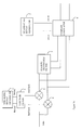
- Figure 3a shows a first embodiment of an SSB spread spectrum signal generator according to the invention comprising a complex spreading signal generator 1 which generates a complex spreading signal, denoted Re(ss) and Im(ss).
- the nature of the complex spreading signal will be described later with reference to Figure 5.
- the complex spreading signal is received by a low pass filter 2 which outputs a filtered complex spreading signal, the real part of which is denoted Re(F(ss)) and the imaginary part of which is denoted Im(F(ss)).
- the filter 2 is implemented as a root raised cosine filter, although any type of low pass filter could be used.
- a data signal modulates the real and imaginary complex spreading signals at modulators 4 and 5 to produce a modulated complex signal.
- the modulated complex signal is then phase shifted by 90 degrees using a Hilbert Transform filter 3 to produce the quadrature counterpart of the complex signal.
- These complex signals are then upconverted to the desired frequency by a complex modulator 6 to provide as an output an SSB spread signal.
- Cosine and sine waves of the desired frequency are provided by a signal generator 7.
- Figure 3b shows an embodiment of the invention in which the complex signal is filtered after modulation by the input data. Equally filtering can be performed after the Hilbert transform, as shown in the embodiment of Figure 3c. This embodiment requires the use of two low pass filters 2' and 2".
- Figure 3d shows an embodiment of the invention in which the upconverted SSB signal is bandlimited by a band pass filter 8.
- Figure 3e shows an embodiment of the invention in which the data modulates the upconverted SSB signal at a modulator 9. It will be appreciated that bandlimiting of the signal can be performed in several ways in a similar manner to the embodiments shown in Figures 3b, 3c and 3d.
- the complex spreading signal generator 1 generates one of a family of complex spreading signals which have good correlation properties.
- the maximum instantaneous frequency is not bandlimited to the Nyquist value for the chipping rate and depends upon r.
- the real and imaginary parts of an FZC sequence are shown in Figure 5a.
- the sequence generated by the complex spreading sequence generator 1 is phase shifted by the Hilbert Transform filter 3 to produce a signal which has been phase shifted by 90 degrees.
- the phase shifted sequence corresponding to the complex sequence of Figure 5a is shown in Figure 5b.
- the complex spreading sequence and the transformed sequence each have good autocorrelation and good cross correlation properties.
- the operations of bandlimiting, applying the Hilbert transform, and upconversion to a broadcast frequency using a complex modulator may be performed in any order, as long as the Hilbert Transform is applied before the upconversion step.
- the order in which the signals are filtered, spread and modulated is different.
- the complex spreading signal from the spreading signal generator 1 may be phase shifted by the Hilbert transform filter 3 and then the complex spreading signal and the phase shifted spreading signal may each be filtered, although in this case two low pass filters would be required.
- Figure 3e shows another alternative embodiment of the invention in which the data is used to modulate the upconverted spread spectrum signal.
- the capacity of the system is potentially increased because either two SSB signals may be used in a single existing UMTS channel or one SSB channel of twice the chipping rate may be employed, as shown schematically in Figure 6.
- a signal employing SSB modulation and a signal employing double sideband modulation should cause minimal interference to each other.
- Figure 7 shows the results of an experiment to measure the BER against the number of users for a system using SSB modulation according to the preferred embodiment of the invention, the BER for a standard UMTS system using double sideband modulation and the BER for a system employing a combination of the techniques, referred to as an 'overlay' in Figure 7.
- Multipath resolution is required when a signal may take a plurality of paths between a transmitter and a receiver. If the multipath resolution is improved, the potential increase in capacity is more than 100%, due to reduced fading and hence decreased interference.
- Figure 8 illustrates how a higher chipping rate can reduce interference, if it is possible to resolve signals received via different paths. It is also possible to constructively combine signals received via different paths so that the performance of a line with multipaths may actually be improved over that of a perfect channel.
- Figure 9 shows how BER varies with the time delay between a line of sight signal and an equal magnitude signal of random phase, representing the same signal received via a different path.
- the chipping rate is 4 Mchip/s with a period of 0.25 s and the Eb/No is 6.8dB resulting in a BER of 1x10 -3 when no multipath interference occurs.
- the sampling point is midway through the chip resulting in the start of the next chip occurring after a delay 0.125 s. It can be seen that the low BER is maintained until the two signals are spaced by less than the chipping period then significant fading (destructive interference) results and the BER increases significantly.
- Figure 10 shows results taken from channel sounding measurements in a typical microcellular environment.
- a significant multipath is defined as paths which have a signal strength within 10 dB of the strongest signal.
- the profile width is plotted against the number of significant multipaths. It can be seen that, in many cases, all of the energy is distributed within a 0.5 s window, even when many paths are contributing. If the chipping period is 0.25 s many separate multipaths will arrive within each chip interval resulting in fading and thus degradation of system performance. Therefore, for much of the time the system is only able to resolve 2 multipaths. Increasing the chip rate not only reduces fading but also yields more resolvable multipaths which could beneficially be combined at the receiver.
- FIG 11 shows a decoder for decoding the transmitted signal of this invention.
- a despreading signal is generated using a spreading signal generator 1', a Hilbert transform filter 3', a quadrature signal generator 7' and a complex modulator 6' in a similar manner to the generation of the spreading signal shown in Figure 3e.
- the transmitted data is demodulated, and despread by a modulator 9, and then low pass filtered by a low pass filter 10 to achieve the decoded signal.
Abstract
This invention relates to a signal generator and decoder for a single sideband spread
spectrum signal.
The present invention provides a single sideband spread spectrum signal generator
and decoder in which single sideband modulation using a complex spreading code is
achieved with improved correlation properties, so that the interference between users
is reduced.
Description
- This invention relates to a signal generator for providing a single sideband (SSB) spread spectrum signal.
- Currently all cellular networks use double sideband modulation to upconvert a baseband signal to a radio frequency. Hence, the same information is conveyed in both sidebands, and the signal uses twice the bandwidth than is absolutely necessary. Single sideband modulation allows the same amount of information to be transmitted using half the bandwidth of double sideband modulation, or alternatively twice the amount of information in the same bandwidth.
- The next generation of cellular networks is known as Universal Mobile Telecommunications Systems (UMTS). Wideband code division multiple access (W-CDMA) will be used for 60MHz of paired spectrum, i.e. two separate bands of 60MHz, the lower band being used for the uplink and the higher band being used for the downlink. The use of W-CDMA facilitates high bit rates for mobile users.
- The capacity of a code division multiple access (CDMA) system is determined by the number of chips per symbol (known as the processing gain) divided by the energy per bit divided by noise power spectral density (Eb/No). If the number of chips per symbol can be increased then the capacity is increased. The maximum chipping rate is limited by the available bandwidth. Single sideband modulation reduces the bandwidth required by a modulated signal by a half. Therefore if a single sideband modulated signal can be produced then either the chipping rate can be increased, or two single sideband signals (upper and lower sideband) may be employed in order to increase the capacity of a CDMA system.
- However, traditional techniques used to produce a single sideband signal, such as bandpass filtering or the well known phasing method cannot be used with data where the spectrum extends down to DC.
- A known method of producing a single sideband signal is shown in Figure 1. However this complex modulator may not be used with traditional spreading codes such as PN code, Walsh codes, Gold code etc. to produce SSB because these codes are binary and do not provide a suitable complex spread spectrum signal. The autocorrelation and cross correlation properties of these signals are good. However, if the signal is transformed (eg. by the Hilbert transform) to produce a quadrature signal, then discontinuities and poor correlation properties result. Poor correlation properties result in an increase in the interference experienced by other users and thus decrease the capacity of the system. Hence, to use a modulator such as that shown in Figure 1 a spreading code is required which has good correlation properties in both the real and imaginary domains if a corresponding increase in capacity is to be achieved.
- Complex spreading codes with the desired properties are known, for example Frank-Zadoff-Chu (FZC) codes as described in "Polyphase codes with good non-periodic correlation properties", R. L. Frank, IEEE Transactions of Information Theory, vol. IT-9, pp. 43-45, Jan. 1963. However, use of these codes produces a spread spectrum signal which is not bandlimited as will be shown later, so that whatever modulation is used the resulting signal would occupy limitless bandwidth. In "A class of bandlimited complex spreading sequences with analytic properties", M. P. Lotter and L. P. Linde, Proc of ISSSTA 95, 22-25 Sept. 1996, it was shown that by limiting the phase shift between successive samples of the sequence to be less than π radians, a bandlimited signal may be obtained and a set of codes called analytic bandlimited complex sequences derived. The penalty paid for this filtering process is that both the autocorrelation and crosscorrelation functions of the codes are no longer ideal so the number of users which may be supported is reduced. So, although the number of chips per symbol is increased in this known system, the resulting poor correlation properties do not result in a corresponding increase in capacity.
- The present invention seeks to alleviate these problems by providing a single sideband spread spectrum signal generator in which single sideband modulation using a complex spreading code is achieved with improved correlation properties, so that the interference between users is reduced.
- According to the present invention there is provided a method of generating a single sideband spread spectrum signal comprising the steps of bandlimiting a signal; phase shifting a complex spreading signal in accordance with a Hilbert Transform; modulating a received signal in accordance with the complex spreading signal and upconverting of a complex signal to a higher frequency; wherein the order in which the steps are performed is immaterial provided that the phase shifting step is performed before the upconversion step.
- In a preferred embodiment of the invention the upconverting step comprises the substeps of modulating a signal of the upconverted complex signal in accordance with the real part of the complex signal combined with the imaginary part of the phase shifted complex signal; and modulating a quadrature signal of the upconverted complex signal in accordance with the imaginary part of the complex signal combined with the real part of the phase shifted complex signal.
- Preferably the complex spreading signal is derived from a sequence defined by the equationwhere

- The bandlimiting step may be performed prior to the phase shifting step or the bandlimiting step may be performed after the upconversion step.
- In some embodiments of the invention the modulation step is performed after the upconversion step.
- According to a second aspect of the invention there is provided an apparatus for generating a single sideband spread spectrum signal, comprising: a complex spreading signal generator; a bandlimiting filter; a phase shifter coupled to receive a spreading signal via the complex spreading signal generator for phase shifting the spreading signal in accordance with a Hilbert Transform; a data modulator connected to receive an input signal; and a complex modulator coupled to receive a complex signal via the phase shifter for upconversion of the complex signal to a single sideband signal.
- In some embodiments of the invention the bandlimiting filter is a low pass filter connected to receive the output of the complex spreading signal generator. In other embodiments of the invention the bandlimiting filter is a band pass filter connected to receive the output of the complex modulator.
- In some embodiments of the invention the data modulator is coupled to receive a second signal via the complex modulator.
- According to another aspect of the invention there is provided a method of decoding a single sideband signal comprising the steps of phase shifting a complex spreading signal in accordance with a Hilbert Transform; upconverting the complex spreading signal to a higher frequency; and demodulating a received signal in accordance with the upconverted complex spreading signal.
- Preferably the complex spreading signal is derived from a sequence defined by the equationwhere

- According to another aspect of the invention there is provided an apparatus for decoding a transmitted signal, comprising: a complex spreading signal generator; a phase shifter connected to receive the complex spreading signal from the complex spreading signal generator; a complex modulator connected to receive the complex spreading signal from the complex spreading signal generator, connected to receive the phase shifted complex spreading signal from the phase shifter and arranged in operation to upconvert the complex spreading signal; and a data modulator connected to receive the transmitted signal and the upconverted complex spreading signal and arranged in operation to demodulate the transmitted signal to provide a decoded transmitted signal.
- Methods of and apparatus for generating and decoding signals according to the present invention will now be described, by way of example only, with reference to the accompanying drawings in which:
- Figure 1 shows a known modulator for producing a single sideband transmission signal from an arbitrary information source;
- Figure 2 shows a known complex modulator for producing a single sideband transmission signal from complex input data.
- Figures 3a to 3e show embodiments of a signal generator according to the invention;
- Figure 4 shows ideal autocorrelation and cross correlation functions for a spreading signal of length 49 chips;
- Figure 5 shows complex spreading signals for use in a signal generator according to the invention;
- Figure 6 shows schematically how a signal generator according to the invention may be employed in different ways to increase capacity in a system;
- Figure 7 is a graph showing bit error rate (BER) against the number of users for a system using a signal generator according to the invention, BER for a standard UMTS system using double sideband modulation and BER for a system employing a combination of the techniques which would represent the evolutionary route in the adoption of the invention where SSB and DSB systems co-exist in the same spectrum;
- Figure 8 illustrates how a higher chipping rate can reduce fading (destructive interference) due to multipath propagation;
- Figure 9 shows how BER varies with the time delay between a line of sight signal and an equal magnitude signal of random phase, representing the same signal received via a different path;
- Figure 10 shows results taken from channel sounding measurements in a typical microcellular environment demonstrating the small inter-arrival delays between multipaths in a dense urban environment; and
- Figure 11 shows a decoder for decoding a signal transmitted according to the invention.
-
- Figure 1 shows a known modulator for producing a SSB. A data signal I and its corresponding quadrature signal Q are modulated at
modulators modulators modulators adder 14 providing anSSB signal 16 and the outputs of themodulators adder 15 to provide anSSB output signal 17. The output at 16 is 90 degrees out of phase with the output at 17. The modulator of Figure 1 provides an upper sideband signal, a lower sideband signal may be produced by changing the sign of one of the inputs to theadders output signals - Figure 2 shows a complex modulator for producing a SSB signal from a complex input signal. Complex signal B is the quadrature counterpart of complex signal A. The imaginary part of complex signal B is subtracted from the real part of complex signal A (via an inverter, not shown) at an
adder 20, and the resultant summed signal is then modulated by a cosine wave of the modulation frequency at amodulator 23. Similarly, the imaginary part of complex signal A is added to the real part of complex signal B at anadder 21, and the summed signal is then modulated by a sine wave of the modulation frequency atmodulator 22. The two modulated signals are summed at anadder 24 to produce an SSB signal. The complex modulator of Figure 2 produces an upper sideband signal, a lower sideband signal may be produced by changing the sign of one of the inputs to theadders - Figure 3a shows a first embodiment of an SSB spread spectrum signal generator according to the invention comprising a complex spreading
signal generator 1 which generates a complex spreading signal, denoted Re(ss) and Im(ss). The nature of the complex spreading signal will be described later with reference to Figure 5. The complex spreading signal is received by alow pass filter 2 which outputs a filtered complex spreading signal, the real part of which is denoted Re(F(ss)) and the imaginary part of which is denoted Im(F(ss)). Thefilter 2 is implemented as a root raised cosine filter, although any type of low pass filter could be used. A data signal modulates the real and imaginary complex spreading signals atmodulators Hilbert Transform filter 3 to produce the quadrature counterpart of the complex signal. These complex signals are then upconverted to the desired frequency by acomplex modulator 6 to provide as an output an SSB spread signal. Cosine and sine waves of the desired frequency are provided by asignal generator 7. - Figure 3b shows an embodiment of the invention in which the complex signal is filtered after modulation by the input data. Equally filtering can be performed after the Hilbert transform, as shown in the embodiment of Figure 3c. This embodiment requires the use of two
low pass filters 2' and 2". Figure 3d shows an embodiment of the invention in which the upconverted SSB signal is bandlimited by aband pass filter 8. - Figure 3e shows an embodiment of the invention in which the data modulates the upconverted SSB signal at a
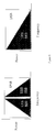
modulator 9. It will be appreciated that bandlimiting of the signal can be performed in several ways in a similar manner to the embodiments shown in Figures 3b, 3c and 3d. - For spread spectrum communications a set of spreading signals is required each of which has an autocorrelation function which is near zero everywhere except at a single maximum per period, and which also has minimum cross correlation functions. It has been shown by D. V. Sarwate in "Bounds on crosscorrelation and autocorrelation of sequences", IEEE Transactions on Information Theory, vol IT-25, pp720-724, that the maximum magnitude of the periodic cross correlation function and the maximum magnitude of the periodic autocorrelation are related, and that if a set of signals has good autocorrelation properties then the cross correlation properties are not very good, and vice versa. Figures 4a and 4b show perfect autocorrelation and ideal cross correlation functions (for a spreading signal of length 49 chips)
- The complex spreading
signal generator 1 generates one of a family of complex spreading signals which have good correlation properties. The codes used in this embodiment of the invention are known as Frank-Zadoff-Chu (FZC) sequences or codes. They are based on the complex roots of unity:where m = 0,1,2,..., N-1 and q is any integer and the number of sequences of a given length is N.
- The maximum instantaneous frequency reached by the sequence {am} is when m = N-1, and can be written as:
- Clearly the maximum instantaneous frequency is not bandlimited to the Nyquist value for the chipping rate and depends upon r. The real and imaginary parts of an FZC sequence are shown in Figure 5a. The sequence generated by the complex spreading
sequence generator 1 is phase shifted by theHilbert Transform filter 3 to produce a signal which has been phase shifted by 90 degrees. The phase shifted sequence corresponding to the complex sequence of Figure 5a is shown in Figure 5b. The complex spreading sequence and the transformed sequence each have good autocorrelation and good cross correlation properties. - The operations of bandlimiting, applying the Hilbert transform, and upconversion to a broadcast frequency using a complex modulator may be performed in any order, as long as the Hilbert Transform is applied before the upconversion step. Hence, in alternative embodiments of the invention the order in which the signals are filtered, spread and modulated is different. For example, referring again to Figure 3, the complex spreading signal from the spreading
signal generator 1 may be phase shifted by the Hilbert transformfilter 3 and then the complex spreading signal and the phase shifted spreading signal may each be filtered, although in this case two low pass filters would be required. Figure 3e shows another alternative embodiment of the invention in which the data is used to modulate the upconverted spread spectrum signal. - The capacity of the system is potentially increased because either two SSB signals may be used in a single existing UMTS channel or one SSB channel of twice the chipping rate may be employed, as shown schematically in Figure 6. For a practical system which allows a smooth transition from a standard using double sideband modulation to a standard using SSB modulation, it is desirable that a signal employing SSB modulation and a signal employing double sideband modulation should cause minimal interference to each other. Figure 7 shows the results of an experiment to measure the BER against the number of users for a system using SSB modulation according to the preferred embodiment of the invention, the BER for a standard UMTS system using double sideband modulation and the BER for a system employing a combination of the techniques, referred to as an 'overlay' in Figure 7.
- An advantage of using an SSB channel of twice the chipping rate is that multipath resolution is improved. Multipath resolution is required when a signal may take a plurality of paths between a transmitter and a receiver. If the multipath resolution is improved, the potential increase in capacity is more than 100%, due to reduced fading and hence decreased interference. Figure 8 illustrates how a higher chipping rate can reduce interference, if it is possible to resolve signals received via different paths. It is also possible to constructively combine signals received via different paths so that the performance of a line with multipaths may actually be improved over that of a perfect channel.
- Figure 9 shows how BER varies with the time delay between a line of sight signal and an equal magnitude signal of random phase, representing the same signal received via a different path. In this example the chipping rate is 4 Mchip/s with a period of 0.25 s and the Eb/No is 6.8dB resulting in a BER of 1x10⁻³ when no multipath interference occurs. In this example the sampling point is midway through the chip resulting in the start of the next chip occurring after a delay 0.125 s. It can be seen that the low BER is maintained until the two signals are spaced by less than the chipping period then significant fading (destructive interference) results and the BER increases significantly.
- Figure 10 shows results taken from channel sounding measurements in a typical microcellular environment. A significant multipath is defined as paths which have a signal strength within 10 dB of the strongest signal. In the graph of Figure 10 the profile width is plotted against the number of significant multipaths. It can be seen that, in many cases, all of the energy is distributed within a 0.5 s window, even when many paths are contributing. If the chipping period is 0.25 s many separate multipaths will arrive within each chip interval resulting in fading and thus degradation of system performance. Therefore, for much of the time the system is only able to resolve 2 multipaths. Increasing the chip rate not only reduces fading but also yields more resolvable multipaths which could beneficially be combined at the receiver.
- Figure 11 shows a decoder for decoding the transmitted signal of this invention. A despreading signal is generated using a spreading signal generator 1', a Hilbert transform filter 3', a quadrature signal generator 7' and a complex modulator 6' in a similar manner to the generation of the spreading signal shown in Figure 3e. The transmitted data is demodulated, and despread by a
modulator 9, and then low pass filtered by alow pass filter 10 to achieve the decoded signal.
Claims (13)
- A method of generating a single sideband spread spectrum signal comprising the steps ofwherein the order in which the steps are performed is immaterial provided that the phase shifting step is performed before the upconversion step.bandlimiting a signal;phase shifting a complex spreading signal in accordance with a Hilbert Transform;modulating a received signal in accordance with the complex spreading signal andupconverting of a complex signal to a higher frequency;
- A method according to claim 1, in which
the upconverting step comprises the substeps ofmodulating a signal of the upconverted complex signal in accordance with the real part of the complex signal combined with the imaginary part of the phase shifted complex signal; andmodulating a quadrature signal of the upconverted complex signal in accordance with the imaginary part of the complex signal combined with the real part of the phase shifted complex signal. - A method according to claim 1 or claim 2, in which the complex spreading signal is derived from a sequence defined by the equationwhere

- A method according to any one of the preceding claims in which the bandlimiting step is performed prior to the phase shifting step.
- A method according to any one of claims 1 to 3 in which the bandlimiting step is performed after the upconversion step.
- A method according to any one of the preceding claims in which the modulation step is performed after the upconversion step.
- An apparatus for transmitting a single sideband spread spectrum signal, comprising:a complex spreading signal generator;a bandlimiting filter;a phase shifter coupled to receive a spreading signal via the complex spreading signal generator for phase shifting the spreading signal in accordance with a Hilbert Transform;a data modulator connected to receive an input signal; anda complex modulator coupled to receive a complex signal via the phase shifter for upconversion of the complex signal to a single sideband signal.
- An apparatus according to claim 7, in which the bandlimiting filter is a low pass filter connected to receive the output of the complex spreading signal generator.
- An apparatus according to claim 7, in which the bandlimiting filter is a band pass filter connected to receive the output of the complex modulator.
- An apparatus according to any one of claims 7 to 9, in which the data modulator is coupled to receive a second signal via the complex modulator.
- A method of decoding a single sideband signal comprising the steps ofphase shifting a complex spreading signal in accordance with a Hilbert Transform;upconverting the complex spreading signal to a higher frequency; anddemodulating a received signal in accordance with the upconverted complex spreading signal.
- A method according to claim 11, in which the complex spreading signal is derived from a sequence defined by the equationwhere

- An apparatus for decoding a transmitted signal, comprising:a complex spreading signal generator;a phase shifter connected to receive the complex spreading signal from the complex spreading signal generator;a complex modulator connected to receive the complex spreading signal from the complex spreading signal generator, connected to receive the phase shifted complex spreading signal from the phase shifter and arranged in operation to upconvert the complex spreading signal; anda data modulator connected to receive the transmitted signal and the upconverted complex spreading signal and arranged in operation to demodulate the transmitted signal to provide a decoded transmitted signal.
Priority Applications (10)
| Application Number | Priority Date | Filing Date | Title |
|---|---|---|---|
| EP99306490A EP1077532A1 (en) | 1999-08-17 | 1999-08-17 | Spread Spectrum Signal Generator and Decoder for Single Sideband Transmission |
| CA2382052A CA2382052C (en) | 1999-08-17 | 2000-08-03 | A single sideband spread spectrum generator using hilbert transform |
| EP00949789A EP1205036B1 (en) | 1999-08-17 | 2000-08-03 | Signal generator and decoder |
| CNB008111855A CN1165114C (en) | 1999-08-17 | 2000-08-03 | Signal generator and decoder |
| AU63057/00A AU6305700A (en) | 1999-08-17 | 2000-08-03 | Signal generator and decoder |
| AT00949789T ATE277459T1 (en) | 1999-08-17 | 2000-08-03 | SIGNAL GENERATOR AND DECODER |
| DE60014113T DE60014113T2 (en) | 1999-08-17 | 2000-08-03 | SIGNAL GENERATOR AND DECODER |
| US10/031,231 US7372891B1 (en) | 1999-08-17 | 2000-08-03 | Signal generator and decoder |
| PCT/GB2000/002997 WO2001013531A1 (en) | 1999-08-17 | 2000-08-03 | Signal generator and decoder |
| JP2001517715A JP4463458B2 (en) | 1999-08-17 | 2000-08-03 | Signal generator and decoder |
Applications Claiming Priority (1)
| Application Number | Priority Date | Filing Date | Title |
|---|---|---|---|
| EP99306490A EP1077532A1 (en) | 1999-08-17 | 1999-08-17 | Spread Spectrum Signal Generator and Decoder for Single Sideband Transmission |
Publications (1)
| Publication Number | Publication Date |
|---|---|
| EP1077532A1 true EP1077532A1 (en) | 2001-02-21 |
Family
ID=8241583
Family Applications (2)
| Application Number | Title | Priority Date | Filing Date |
|---|---|---|---|
| EP99306490A Withdrawn EP1077532A1 (en) | 1999-08-17 | 1999-08-17 | Spread Spectrum Signal Generator and Decoder for Single Sideband Transmission |
| EP00949789A Expired - Lifetime EP1205036B1 (en) | 1999-08-17 | 2000-08-03 | Signal generator and decoder |
Family Applications After (1)
| Application Number | Title | Priority Date | Filing Date |
|---|---|---|---|
| EP00949789A Expired - Lifetime EP1205036B1 (en) | 1999-08-17 | 2000-08-03 | Signal generator and decoder |
Country Status (9)
| Country | Link |
|---|---|
| US (1) | US7372891B1 (en) |
| EP (2) | EP1077532A1 (en) |
| JP (1) | JP4463458B2 (en) |
| CN (1) | CN1165114C (en) |
| AT (1) | ATE277459T1 (en) |
| AU (1) | AU6305700A (en) |
| CA (1) | CA2382052C (en) |
| DE (1) | DE60014113T2 (en) |
| WO (1) | WO2001013531A1 (en) |
Cited By (2)
| Publication number | Priority date | Publication date | Assignee | Title |
|---|---|---|---|---|
| US6961691B1 (en) | 2000-03-30 | 2005-11-01 | Mentor Graphics Corporation | Non-synchronized multiplex data transport across synchronous systems |
| CN111585928A (en) * | 2020-04-28 | 2020-08-25 | 中国电子科技集团公司第三研究所 | Voice signal single-sideband modulation and demodulation method and device |
Families Citing this family (11)
| Publication number | Priority date | Publication date | Assignee | Title |
|---|---|---|---|---|
| JP3643366B2 (en) * | 2003-07-10 | 2005-04-27 | 松下電器産業株式会社 | CDMA transmitter and CDMA receiver |
| CN100410925C (en) * | 2004-12-30 | 2008-08-13 | 中国科学院长春光学精密机械与物理研究所 | Digital signal processing method for ultrasonic signals |
| EP1955509A4 (en) | 2005-11-28 | 2011-07-06 | Lg Electronics Inc | Method and apparatus for generating and transmitting code sequence in a wireless communication system |
| EP1985023A4 (en) * | 2006-01-25 | 2014-08-13 | Texas Instruments Inc | Method and apparatus for increasing the number of orthogonal signals using block spreading |
| US8369860B2 (en) | 2006-08-18 | 2013-02-05 | Interdigital Technology Corporation | Sending and reducing uplink feedback signaling for transmission of MBMS data |
| JP2008085921A (en) * | 2006-09-28 | 2008-04-10 | Matsushita Electric Ind Co Ltd | Radio transmission apparatus and radio receiving apparatus |
| WO2008038790A1 (en) * | 2006-09-29 | 2008-04-03 | Panasonic Corporation | Sequence allocating method and sequence allocating apparatus |
| JP4786583B2 (en) * | 2007-04-04 | 2011-10-05 | パナソニック株式会社 | SSB signal forming method and wireless transmission apparatus |
| CN101257319B (en) * | 2008-04-09 | 2011-07-20 | 浙江大学 | Complete digital logarithm automatic gain control device and method |
| JP5131550B2 (en) * | 2008-07-23 | 2013-01-30 | 株式会社カオスウェア | Spreading code calculation device, communication system, transmission device, reception device, and program |
| CN108199996B (en) * | 2017-11-21 | 2020-07-14 | 上海微波技术研究所(中国电子科技集团公司第五十研究所) | FPGA-based independent sideband modulation signal demodulation method |
Citations (3)
| Publication number | Priority date | Publication date | Assignee | Title |
|---|---|---|---|---|
| US5422909A (en) * | 1993-11-30 | 1995-06-06 | Motorola, Inc. | Method and apparatus for multi-phase component downconversion |
| US5675608A (en) * | 1994-06-17 | 1997-10-07 | Samsung Electronics Co., Ltd. | Synchronous transmitter and receiver of spread spectrum communication method |
| US5838719A (en) * | 1993-11-02 | 1998-11-17 | Interdigital Technology Corporation | Noise shaping technique for spread spectrum communications |
Family Cites Families (13)
| Publication number | Priority date | Publication date | Assignee | Title |
|---|---|---|---|---|
| US4726069A (en) * | 1984-05-18 | 1988-02-16 | Stevenson Carl R | A muiti-mode modulation and demodulation system and method |
| US5434577A (en) * | 1989-11-17 | 1995-07-18 | Baghdady; Elie J. | Signal modulation methods and apparatus |
| US5619503A (en) * | 1994-01-11 | 1997-04-08 | Ericsson Inc. | Cellular/satellite communications system with improved frequency re-use |
| EP0931388B1 (en) * | 1996-08-29 | 2003-11-05 | Cisco Technology, Inc. | Spatio-temporal processing for communication |
| CA2197624C (en) * | 1997-02-14 | 2003-07-29 | Robert J. Davies | Hybrid single sideband optical modulator |
| US6005894A (en) * | 1997-04-04 | 1999-12-21 | Kumar; Derek D. | AM-compatible digital broadcasting method and system |
| US5937006A (en) * | 1997-05-28 | 1999-08-10 | The Aerospace Corporation | Frequency translating device transmission response method |
| KR100365346B1 (en) * | 1997-09-09 | 2003-04-11 | 삼성전자 주식회사 | Apparatus and method for generating quasi-orthogonal code of mobile communication system and diffusing band by using quasi-orthogonal code |
| US6389000B1 (en) * | 1997-09-16 | 2002-05-14 | Qualcomm Incorporated | Method and apparatus for transmitting and receiving high speed data in a CDMA communication system using multiple carriers |
| US6288610B1 (en) * | 1998-03-19 | 2001-09-11 | Fujitsu Limited | Method and apparatus for correcting signals, apparatus for compensating for distortion, apparatus for preparing distortion compensating data, and transmitter |
| CA2311788C (en) * | 1998-09-29 | 2003-12-16 | Samsung Electronics Co., Ltd. | Device and method for generating spreading code and spreading channel signals using spreading code in cdma communication system |
| US6430213B1 (en) * | 1999-05-26 | 2002-08-06 | The Aerospace Corporation | Coherent adaptive subcarrier modulation method |
| US6798843B1 (en) * | 1999-07-13 | 2004-09-28 | Pmc-Sierra, Inc. | Wideband digital predistortion linearizer for nonlinear amplifiers |
-
1999
- 1999-08-17 EP EP99306490A patent/EP1077532A1/en not_active Withdrawn
-
2000
- 2000-08-03 CN CNB008111855A patent/CN1165114C/en not_active Expired - Lifetime
- 2000-08-03 JP JP2001517715A patent/JP4463458B2/en not_active Expired - Lifetime
- 2000-08-03 AU AU63057/00A patent/AU6305700A/en not_active Abandoned
- 2000-08-03 WO PCT/GB2000/002997 patent/WO2001013531A1/en active IP Right Grant
- 2000-08-03 CA CA2382052A patent/CA2382052C/en not_active Expired - Fee Related
- 2000-08-03 AT AT00949789T patent/ATE277459T1/en not_active IP Right Cessation
- 2000-08-03 US US10/031,231 patent/US7372891B1/en not_active Expired - Lifetime
- 2000-08-03 EP EP00949789A patent/EP1205036B1/en not_active Expired - Lifetime
- 2000-08-03 DE DE60014113T patent/DE60014113T2/en not_active Expired - Lifetime
Patent Citations (3)
| Publication number | Priority date | Publication date | Assignee | Title |
|---|---|---|---|---|
| US5838719A (en) * | 1993-11-02 | 1998-11-17 | Interdigital Technology Corporation | Noise shaping technique for spread spectrum communications |
| US5422909A (en) * | 1993-11-30 | 1995-06-06 | Motorola, Inc. | Method and apparatus for multi-phase component downconversion |
| US5675608A (en) * | 1994-06-17 | 1997-10-07 | Samsung Electronics Co., Ltd. | Synchronous transmitter and receiver of spread spectrum communication method |
Non-Patent Citations (1)
| Title |
|---|
| LOTTER M P ET AL: "A class of bandlimited complex spreading sequences with analytic properties", 1996 IEEE 4TH INTERNATIONAL SYMPOSIUM ON SPREAD SPECTRUM TECHNIQUES AND APPLICATIONS PROCEEDINGS. TECHNICAL PROGRAM. (CAT. NO.96TH8210), PROCEEDINGS OF ISSSTA'95 INTERNATIONAL SYMPOSIUM ON SPREAD SPECTRUM TECHNIQUES AND APPLICATIONS, MAINZ, GERMANY,, 1996, New York, NY, USA, IEEE, USA, pages 662 - 666 vol.2, XP002127399, ISBN: 0-7803-3567-8 * |
Cited By (3)
| Publication number | Priority date | Publication date | Assignee | Title |
|---|---|---|---|---|
| US6961691B1 (en) | 2000-03-30 | 2005-11-01 | Mentor Graphics Corporation | Non-synchronized multiplex data transport across synchronous systems |
| CN111585928A (en) * | 2020-04-28 | 2020-08-25 | 中国电子科技集团公司第三研究所 | Voice signal single-sideband modulation and demodulation method and device |
| CN111585928B (en) * | 2020-04-28 | 2023-05-05 | 中国电子科技集团公司第三研究所 | Single sideband modulation and demodulation method and device for voice signal |
Also Published As
| Publication number | Publication date |
|---|---|
| WO2001013531A1 (en) | 2001-02-22 |
| CA2382052A1 (en) | 2001-02-22 |
| CN1367955A (en) | 2002-09-04 |
| AU6305700A (en) | 2001-03-13 |
| EP1205036A1 (en) | 2002-05-15 |
| EP1205036B1 (en) | 2004-09-22 |
| ATE277459T1 (en) | 2004-10-15 |
| DE60014113D1 (en) | 2004-10-28 |
| US7372891B1 (en) | 2008-05-13 |
| JP2003507924A (en) | 2003-02-25 |
| CA2382052C (en) | 2010-10-19 |
| DE60014113T2 (en) | 2006-02-23 |
| CN1165114C (en) | 2004-09-01 |
| JP4463458B2 (en) | 2010-05-19 |
Similar Documents
| Publication | Publication Date | Title |
|---|---|---|
| US7440486B2 (en) | Noise shaping technique for spread spectrum communications | |
| US7095778B2 (en) | Spread spectrum transmitter and spread spectrum receiver | |
| US6404732B1 (en) | Digital modulation system using modified orthogonal codes to reduce autocorrelation | |
| US8040935B2 (en) | Methods and apparatus for spread spectrum modulation and demodulation | |
| US5353301A (en) | Method and apparatus for combining multipath spread-spectrum signals | |
| US20080069257A1 (en) | M-ary orthogonal keying system | |
| EP1271797B1 (en) | Re-orthogonalization of wideband CDMA signals | |
| EP1205036B1 (en) | Signal generator and decoder | |
| US20060198522A1 (en) | Wide band-DCSK modulation method, transmitting apparatus thereof, wide band-DCSK demodulation method, and receiving apparatus thereof | |
| US6674790B1 (en) | System and method employing concatenated spreading sequences to provide data modulated spread signals having increased data rates with extended multi-path delay spread | |
| US7894504B2 (en) | Coherent and non-coherent hybrid direct sequence/frequency hopping spread spectrum systems with high power and bandwidth efficiency and methods thereof | |
| US6246697B1 (en) | Method and system for generating a complex pseudonoise sequence for processing a code division multiple access signal | |
| JPH08251117A (en) | Multicarrier transmission system and method thereof | |
| US6331998B1 (en) | Partially matched filter for spread spectrum communication | |
| JP3002944B2 (en) | Spread spectrum communication system | |
| US5796959A (en) | Noise shaping technique for spread spectrum communications | |
| WO2015129195A1 (en) | Wireless transmission device, wireless reception device, wireless communication system, and wireless communication method | |
| GB2233860A (en) | "Extending the range of radio transmissions" | |
| JP2000114921A (en) | Surface acoustic wave matching filter for spread spectrum signal demodulation and delay detection system |
Legal Events
| Date | Code | Title | Description |
|---|---|---|---|
| PUAI | Public reference made under article 153(3) epc to a published international application that has entered the european phase |
Free format text: ORIGINAL CODE: 0009012 |
|
| AK | Designated contracting states |
Kind code of ref document: A1 Designated state(s): AT BE CH CY DE DK ES FI FR GB GR IE IT LI LU MC NL PT SE |
|
| AX | Request for extension of the european patent |
Free format text: AL;LT;LV;MK;RO;SI |
|
| STAA | Information on the status of an ep patent application or granted ep patent |
Free format text: STATUS: THE APPLICATION IS DEEMED TO BE WITHDRAWN |
|
| 18D | Application deemed to be withdrawn |
Effective date: 20001219 |