EP1079051A1 - Locking device - Google Patents
Locking device Download PDFInfo
- Publication number
- EP1079051A1 EP1079051A1 EP00112750A EP00112750A EP1079051A1 EP 1079051 A1 EP1079051 A1 EP 1079051A1 EP 00112750 A EP00112750 A EP 00112750A EP 00112750 A EP00112750 A EP 00112750A EP 1079051 A1 EP1079051 A1 EP 1079051A1
- Authority
- EP
- European Patent Office
- Prior art keywords
- locking device
- housing
- shaft
- locking
- holding part
- Prior art date
- Legal status (The legal status is an assumption and is not a legal conclusion. Google has not performed a legal analysis and makes no representation as to the accuracy of the status listed.)
- Granted
Links
Images
Classifications
-
- E—FIXED CONSTRUCTIONS
- E05—LOCKS; KEYS; WINDOW OR DOOR FITTINGS; SAFES
- E05B—LOCKS; ACCESSORIES THEREFOR; HANDCUFFS
- E05B47/00—Operating or controlling locks or other fastening devices by electric or magnetic means
- E05B47/06—Controlling mechanically-operated bolts by electro-magnetically-operated detents
- E05B47/0657—Controlling mechanically-operated bolts by electro-magnetically-operated detents by locking the handle, spindle, follower or the like
- E05B47/0665—Controlling mechanically-operated bolts by electro-magnetically-operated detents by locking the handle, spindle, follower or the like radially
- E05B47/0673—Controlling mechanically-operated bolts by electro-magnetically-operated detents by locking the handle, spindle, follower or the like radially with a rectilinearly moveable blocking element
-
- E—FIXED CONSTRUCTIONS
- E05—LOCKS; KEYS; WINDOW OR DOOR FITTINGS; SAFES
- E05B—LOCKS; ACCESSORIES THEREFOR; HANDCUFFS
- E05B47/00—Operating or controlling locks or other fastening devices by electric or magnetic means
- E05B47/06—Controlling mechanically-operated bolts by electro-magnetically-operated detents
- E05B47/0611—Cylinder locks with electromagnetic control
- E05B47/0615—Cylinder locks with electromagnetic control operated by handles, e.g. by knobs
-
- E—FIXED CONSTRUCTIONS
- E05—LOCKS; KEYS; WINDOW OR DOOR FITTINGS; SAFES
- E05B—LOCKS; ACCESSORIES THEREFOR; HANDCUFFS
- E05B47/00—Operating or controlling locks or other fastening devices by electric or magnetic means
- E05B47/06—Controlling mechanically-operated bolts by electro-magnetically-operated detents
- E05B47/0611—Cylinder locks with electromagnetic control
- E05B47/0619—Cylinder locks with electromagnetic control by blocking the rotor
- E05B47/0626—Cylinder locks with electromagnetic control by blocking the rotor radially
- E05B47/063—Cylinder locks with electromagnetic control by blocking the rotor radially with a rectilinearly moveable blocking element
-
- G—PHYSICS
- G07—CHECKING-DEVICES
- G07C—TIME OR ATTENDANCE REGISTERS; REGISTERING OR INDICATING THE WORKING OF MACHINES; GENERATING RANDOM NUMBERS; VOTING OR LOTTERY APPARATUS; ARRANGEMENTS, SYSTEMS OR APPARATUS FOR CHECKING NOT PROVIDED FOR ELSEWHERE
- G07C9/00—Individual registration on entry or exit
- G07C9/00174—Electronically operated locks; Circuits therefor; Nonmechanical keys therefor, e.g. passive or active electrical keys or other data carriers without mechanical keys
- G07C9/00944—Details of construction or manufacture
-
- E—FIXED CONSTRUCTIONS
- E05—LOCKS; KEYS; WINDOW OR DOOR FITTINGS; SAFES
- E05B—LOCKS; ACCESSORIES THEREFOR; HANDCUFFS
- E05B47/00—Operating or controlling locks or other fastening devices by electric or magnetic means
- E05B47/0001—Operating or controlling locks or other fastening devices by electric or magnetic means with electric actuators; Constructional features thereof
- E05B47/0002—Operating or controlling locks or other fastening devices by electric or magnetic means with electric actuators; Constructional features thereof with electromagnets
- E05B47/0006—Operating or controlling locks or other fastening devices by electric or magnetic means with electric actuators; Constructional features thereof with electromagnets having a non-movable core; with permanent magnet
Abstract
Description
Die Erfindung betrifft eine Schließeinrichtung mit einem in einem Gehäuse bewegbaren, zum wahlweisen Verriegeln oder Entriegeln der Schlieißeinrichtung vorgesehenen Kern, mit einem topfförmigen Griff zur Übertragung einer Bewegung auf den Kern und mit einer innerhalb des Griffs angeordneten Steuerelektronik zur Ansteuerung eines Sperrmechanismus, wobei der Sperrmechanismus zur Erzeugung oder Lösung eines Formschlusses zwischen dem Kern und dem Gehäuse ausgebildet ist.The invention relates to a locking device with a Movable in a housing for optional locking or unlocking the locking device provided core, with a pot-shaped handle to transmit movement on the core and with one arranged inside the handle Control electronics for controlling a locking mechanism, the locking mechanism being used to generate or release of a positive connection between the core and the Housing is formed.
Solche Schließeinrichtungen werden bei heutigen Zugriffskontrollanlagen häufig eingesetzt und sind aus der Praxis bekannt. Die Steuerelektronik läßt sich bei den bekannten Schließeinrichtungen beispielsweise mit einem Code von einem Transponderchip, einem Magnetstreifen oder einer Tastatur ansteuern. Die Steuerelektronik überprüft den Code und gibt im Falle einer Zugangsberechtigung ein Schaltsignal an den Sperrmechanismus weiter. Der Sperrmechanismus hebt im Falle der Zugangsberechtigung den Formschluß zwischen dem Kern und dem Gehäuse auf, so daß der Griff zum Entriegeln der Schließeinrichtung gedreht werden kann. Die Steuerelektronik der bekannten Schließeinrichtung ist an der Innenseite des Griffs befestigt und bildet mit dem Griff eine platzsparende bauliche Einheit. Vorteile von solchen Schließeinrichtungen bestehen beispielsweise darin, daß sich die Zugangsberechtigung auf Zeitzonen begrenzen oder bei einem Verlust des Transponderchips oder des Magnetstreifens einfach sperren läßt. Such locking devices are used in today's access control systems frequently used and are from practice known. The control electronics can be in the known Locking devices, for example with a code of a transponder chip, a magnetic stripe or one Activate keyboard. The control electronics checks the Code and enter in case of access authorization Switch signal to the locking mechanism. The locking mechanism abolishes the form closure in the case of access authorization between the core and the housing so that the Handle to unlock the locking device can be turned can. The control electronics of the known locking device is attached to the inside of the handle and forms a space-saving structural unit with the handle. There are advantages of such locking devices, for example in that the access authorization is based on Limit time zones or if the transponder chip is lost or simply lock the magnetic strip.
Nachteilig bei der bekannten Schließeinrichtung ist, daß sich die Steuerelektronik mit dem Griff mitdreht. Dies führt bei in dem Gehäuse angeordnetem Sperrmechanismus oder bei einem feststehenden Lesegerät für den Transponder oder den Magnetstreifen dazu, daß die Übertragung von elektrischer Energie oder elektronischen Signalen zwischen dem Kern und dem Gehäuse beispielsweise Schleifkontakte oder Induktionsschleifen erfordert. Hierdurch ist die Schließeinrichtung jedoch manipulierbar und zudem störanfällig. Weiterhin gestaltet sich die Wartung der Steuerelektronik sehr aufwendig, da sie auch nach einer Entfernung des Griffs nur schwer zugänglich ist.A disadvantage of the known locking device is that the control electronics turn with the handle. This leads with the locking mechanism arranged in the housing or with a fixed reader for the transponder or the magnetic stripe so that the transmission of electrical energy or electronic signals between the core and the housing, for example, sliding contacts or induction loops. This is however, the locking device can be manipulated and also prone to failure. The maintenance of the Control electronics very complex, since they can also be Removal of the handle is difficult to access.
Der Erfindung liegt das Problem zugrunde, eine Schließeinrichtung der eingangs genannten Art so zu gestalten, daß sie eine besonders hohe Zuverlässigkeit aufweist und möglichst einfach zu warten ist.The invention is based on the problem of a To design the locking device of the type mentioned at the beginning that it has a particularly high reliability and is as easy to maintain as possible.
Dieses Problem wird erfindungsgemäß dadurch gelöst, daß die Steuerelektronik und der Sperrmechanismus drehfest mit dem Gehäuse verbunden sind.This problem is solved according to the invention in that the control electronics and the locking mechanism are non-rotatable are connected to the housing.
Durch diese Gestaltung benötigt die erfindungsgemäße Schließeinrichtung keine Schleifkontakte oder Induktionsschleifen zur Übertragung von elektrischer Energie oder Steuersignalen zwischen dem Kern und dem Gehäuse oder dem Lesegerät. Die erfindungsgemäße Schließeinrichtung ist daher besonders zuverlässig gegen Manipulationen und Störungen geschützt. Weiterhin ist die Steuerelektronik nach einer Entfernung des Griffs einfach zu warten, uni beispielsweise eine Batterie zu überprüfen oder zu wechseln.Due to this design, the invention requires Locking device no sliding contacts or induction loops for the transmission of electrical energy or Control signals between the core and the housing or the Reader. The locking device according to the invention is therefore particularly reliable against manipulation and interference protected. Furthermore, the control electronics are after easy to wait to remove the handle, for example to check or replace a battery.
Die erfindungsgemäße Schließeinrichtung gestaltet sich konstruktiv besonders einfach, wenn das Gehäuse einen den Kern umgreifenden Flansch zur Halterung der Steuerelektronik aufweist. The locking device according to the invention is designed structurally particularly simple if the housing one Core encompassing flange for mounting the control electronics having.
Die Elektronik ist nach der Montage der erfindungsgemäßen Schließeinrichtung von außen nicht zugänglich, wenn eine mit dem Kern verbundene Welle mit dem Bodenbereich des Griffs von innen her verschraubt ist.The electronics is after assembly of the invention Locking device not accessible from the outside if one shaft connected to the core with the bottom portion of the Handle is screwed from the inside.
Eine Entfernung des Griffs ohne Zugangsberechtigung läßt sich gemäß einer anderen vorteilhaften Weiterbildung der Erfindung einfach verhindern, wenn die Welle unlösbar mit dem Griff verbunden, vorzugsweise mit diesem einstückig ausgebildet ist. Hierdurch muß zum Entfernen des Griffes die mit dein Kern verbundene Welle aus dem Gehäuse entnommen werden. Da der Kern jedoch in verriegelter Stellung der Schließeinrichtung mit dem Gehäuse formschlüssig verbunden ist, läßt sich der Griff erst nach einem Entriegeln der Schließeinrichtung entfernen. Der Griff kann beispielsweise aus Kunststoff gefertigt und an der Welle angespritzt sein.Removal of the handle without access authorization leaves according to another advantageous development of the Simply prevent invention if the shaft is unsolvable connected to the handle, preferably in one piece with this is trained. This must remove the handle removed the shaft connected to your core from the housing become. However, since the core is in the locked position the locking device is positively connected to the housing the handle can only be unlocked remove the locking device. The handle can for example made of plastic and on the shaft be injected.
Der Kern könnte beispielsweise einstückig gefertigt sein und bei einem Lösen des Formschlusses mit dem Gehäuse einfach aus diesem entnehmbar sein. Die Handhabung der erfindungsgemäßen Schließeinrichtung gestaltet sich jedoch besonders einfach, wenn der Kern eine mit der Welle verbundene und in entriegelter Stellung der Schließeinrichtung lösbare Hülse aufweist und wenn die Hülse in dem Gehäuse axial geführt ist. Hierdurch läßt sich der Griff nach einer Entriegelung der Schließeinrichtung erst abnehmen, wenn die Hülse von der Welle getrennt wurde.The core could, for example, be made in one piece and when the positive connection is released with the housing just be removable from this. The handling of the However, the locking device according to the invention is designed especially easy if the core is one with the shaft connected and in the unlocked position of the locking device has detachable sleeve and if the sleeve in the Housing is guided axially. This allows the handle only remove after unlocking the locking device, when the sleeve has been separated from the shaft.
Die Hülse und die Welle lassen sich gemäß einer anderen vorteilhaften Weiterbildung der Erfindung einfach formschlüssig miteinander verbinden, wenn die Hülse und die Welle eine fluchtende Ausnehmung zur paßgenauen Aufnahme eines die Hülse mit der Welle formschlüssig verbindenden Halteteils aufweisen und wenn das Gehäuse zur Halterung des Halteteils bei verriegelter Schließeinrichtung in der Ausnehmung gestaltet ist. Bei verriegelter Schließeinrichtung läßt sich zudem die Welle und damit der einteilig mit der Welle verbundene Griff nicht aus der Hülse und damit aus dem Gehäuse herausziehen.The sleeve and the shaft can be made according to another advantageous development of the invention simply positive connect with each other when the sleeve and the Wave an aligned recess for a precise fit one that positively connects the sleeve to the shaft Have holding part and if the housing for mounting of the holding part when the locking device is locked in the Recess is designed. When the locking device is locked can also the shaft and thus the one-piece handle connected to the shaft not out of the sleeve and pull it out of the housing.
Eine Trennung des Formschlusses zwischen der Hülse und der Welle gestaltet sich gemäß einer anderen vorteilhaften Weiterbildung der Erfindung konstruktiv besonders einfach, wenn das Halteteil bei entriegelter Schließeinrichtung mittelbar oder unmittelbar von einem von der Außenseite des Gehäuses bewegbaren Riegel gehalten ist. Hierdurch läßt sich nach einer Entriegelung der Schließeinrichtung und einer Bewegung des Riegels das Halteteil aus der Ausnehmung entfernen. Anschließend läßt sich der Griff zusammen mit der Welle von dem Gehäuse trennen.A separation of the form fit between the sleeve and the shaft is designed according to another advantageous one Further development of the invention is particularly constructive easy if the holding part with the locking device unlocked indirectly or directly from one of the outside the housing movable latch is held. This can be after unlocking the Locking device and a movement of the bolt that Remove the holding part from the recess. Then leaves the handle together with the shaft from the housing separate.
Der Riegel läßt sich an einer besonders leicht zugänglichen und von dem Halteteil entfernten Stelle des Gehäuses anordnen, wenn das Halteteil auf einem von dem Riegel verschiebbaren Stift aufliegt und wenn der Stift in eine ein Entfernen des Halteteils aus der Ausnehmung ermöglichende Position bewegbar ist.The latch can be accessed on a particularly easily accessible and away from the holding part of the housing arrange when the holding part is on one of the latches sliding pin rests and when the pin is in a enabling removal of the holding part from the recess Position is movable.
Die Bewegung des Halteteils aus der oder in die Ausnehmung erfordert gemäß einer anderen vorteilhaften Weiterbildung der Erfindung einen besonders geringen baulichen Aufwand, wenn der Riegel einen in dem Gehäuse gelagerten zylindrischen Abschnitt und einen den Stift halternden Exzenter aufweist und wenn der zylindrische Abschnitt Mittel zum Ansetzen eines Drehwerkzeugs hat.The movement of the holding part out of or into the recess requires according to another advantageous training the invention a particularly low structural Effort if the bolt is stored in the housing cylindrical section and a holding the pin Has eccentric and if the cylindrical section Has means for attaching a turning tool.
Ein Klemmen des Halteteils in der Ausnehmung läßt sich gemäß einer anderen vorteilhaften Weiterbildung der Erfindung einfach vermeiden, wenn das Halteteil als Kugel ausgebildet ist und wenn eine Trennebene zwischen der Hülse und der Welle im Bereich der zu der Achse der Welle weisenden Hälfte des Halteteils verläuft. Hierdurch wird das Halteteil von der Trennebene weg nach radial außen und damit gegen das Gehäuse oder den vom Riegel gehaltenen Stift gedrückt.The holding part can be clamped in the recess according to another advantageous development of the invention just avoid if the holding part is a ball is formed and if a dividing plane between the Sleeve and the shaft in the area of the axis of the shaft pointing half of the holding part runs. This will the holding part radially outward from the parting plane and thus against the housing or the one held by the bolt Pin pressed.
Die erfindungsgemäße Schließeinrichtung hat eine besonders hohe Zuverlässigkeit, wenn die Hülse mit dem Sperrmechanismus zusammenarbeitet.The locking device according to the invention has a special high reliability when the sleeve with the locking mechanism works together.
Der Schließmechanismus ermöglicht eine nahezu beliebige Kombination von Griffen und Schließmechanismen an seinen Enden, wenn zwischen der Hülse und einem die Schließeinrichtung verriegelnden Schließbart eine von dem zweiten Griff betätigbare Kupplung angeordnet ist. Hierdurch kann mit dein zweiten Griff beispielsweise die Schließeinrichtung ohne Abfrage einer Zugangsberechtigung oder von einem Schlüssel zu betätigende mechanische Stiftzuhaltungen zugeordnet werden.The locking mechanism enables almost any Combination of handles and locking mechanisms on his Ends when between the sleeve and one the locking device interlocking lock bit one of the second Handle actuated clutch is arranged. This can with your second handle, for example, the locking device without asking for an access authorization or one Mechanical pin tumblers to be operated be assigned.
Die erfindungsgemäße Schließeinrichtung gestaltet sich besonders kompakt, wenn die Welle als Hohlwelle zur Aufnahme von Bauteilen der Kupplung ausgebildet ist.The locking device according to the invention is designed particularly compact if the shaft is used as a hollow shaft for receiving is formed by components of the clutch.
Die Erfindung läßt zahlreiche Ausführungsformen zu. Zur weiteren Verdeutlichung ihres Grundprinzips ist eine davon in der Zeichnung dargestellt und wird nachfolgend beschrieben. Diese zeigt in
- Fig.1
- einen Längsschnitt durch eine erfindungsgemäße Schließeinrichtung,
- Fig.2
- einen Schnitt durch die Schließeinrichtung
aus
Figur 1 entlang der Linie II - II.
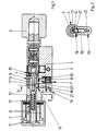
- Fig. 1
- a longitudinal section through a locking device according to the invention,
- Fig. 2
- a section through the locking device of Figure 1 along the line II - II.
Figur 1 zeigt eine als Doppelprofil-Schließzylinder ausgebildete
Schließeinrichtung mit einem Gehäuse 1 und zwei
einander gegenüberstehenden Griffen 2, 3. Die Griffe 2, 3
sind jeweils drehfest auf Enden eines in dem Gehäuse 1
gelagerten Kerns 4 oder einer mit dein Kern 4 verbundenen
Welle 13 befestigt. In der Mitte zwischen den Griffen 2,
3 hat der Kern 4 einen Schließbart 5 zum wahlweisen Verriegeln
oder Entriegeln der Schließeinrichtung. Einer der
Griffe 2 ist zur Aufnahme einer Steuerelektronik 6 topfförmig
gestaltet. Die Steuerelektronik 6 erfaßt eine Zugangsberechtigung
für die Schließeinrichtung. Im Falle
einer Zugangsberechtigung steuert die Steuerelektronik 6
einen einen Formschluß des Gehäuses 1 mit dem Kern 4 erzeugenden
Sperrmechanismus 7 an. Der Sperrmechanismus 7
weist einen von einem Elektromagneten 8 in eine Ausnehmung
9 bewegbaren Sperriegel 10 auf. In der eingezeichneten
Stellung befindet sich die Ausnehmung 9 auf der gegenüberliegenden
Seite des Sperriegels 10. Dies kennzeichnet
die Offenstellung der Schließeinrichtung. Bei
einer Drehung des topfförmigen Griffs 2 um 180° um seine
Achse schnappt der Sperriegel 10 in die Ausnehmung 9 ein.
Zur Stromversorgung der Steuerelektronik 6 und des Sperrmechanismus
7 ist in dem die Steuerelektronik 6 übergreifenden
Griff 2 eine Batterie 11 angeordnet.FIG. 1 shows a double-profile locking cylinder
Locking device with a
Die Zugangsberechtigung kann auf vielfältige Weise ermittelt
werden. Beispielsweise kann die Steuerelektronik 6
einen Code eines vor den topfförmigen Griff 2 oder in ein
nicht dargestelltes Lesegerät gehaltenen Transponders
empfangen und auswerten. Aus dem Code wird mit einem
Speicherinhalt verglichen und in Abhängigkeit von dem
Vergleich die Zugangsberechtigung festgestellt oder verneint.
Alternativ dazu kann die Steuerelektronik 6 auch
mit einer ebenfalls nicht dargestellten, neben der
Schließeinrichtung angeordneten Tastatur eine Zahlenkombination
abfragen oder ein Entriegeln der Schließeinrichtung
nur während eines Zeitfensters zulassen.The access authorization can be determined in a variety of ways
become. For example, the control electronics 6
a code in front of the pot-
Das Gehäuse 1 hat einen Flansch 12 zur Halterung der
Steuerelektronik 6. Im Zentrum des Flansches 12 ist die
mit dem Kern 4 verbundene Welle 13 hindurchgeführt. Die
Welle 13 ist als Hohlwelle ausgebildet und mit dem Bodenbereich
des topfförmigen Griffs 2 verschweißt. Die Welle
13 ist in der eingezeichneten Normalstellung der
Schließeinrichtung drehfest mit einer Hülse 14 verbunden.
Die Hülse 14 ist über eine Kupplung 15 drehfest mit dem
Schließbart 5 verbunden und hat die Ausnehmung 9 für den
Sperrmechanismus 7. Hierdurch läßt sich der die Steuerelektronik
6 übergreifende Griff 2 nur bei entriegeltem
Sperrmechanismus 7 drehen.The
Die Hülse 14 und die Welle 13 weisen eine fluchtende Ausnehmung
16 auf. In der Ausnehmung 16 ist ein Halteteil 17
zur Erzeugung eines Formschlusses zwischen der Welle 13
und der Hülse 14 angeordnet. In der eingezeichneten entriegelten
Stellung des Schließmechanismus liegt das Halteteil
17 auf einem Stift 18 auf. Der Stift 18 wird von
einem Riegel 19 mit einem Exzenter 20 gehalten. Der Riegel
19 ist mit einem zylindrischen Abschnitt 21 in dem
Gehäuse 1 gelagert. Durch eine Drehung des Riegels 19
läßt sich der Stift 18 nach unten hin bewegen, so daß das
Halteteil 17 aus der Ausnehmung 16 herausfallen kann.
Hierdurch wird die drehfeste Verbindung der Hülse 14 mit
der Welle 13 gelöst. Der topfförmige Griff 2 kann damit
zusammen mit der Welle 13 aus dem Gehäuse 1 gezogen werden,
um beispielsweise die Batterie 11 zu wechseln.The
Durch eine Drehung des Kerns 4 mittels des zweiten Griffs
3 läßt sich die Kupplung 15 trennen und damit die drehfeste
Verbindung zwischen dem Schließbart 5 und der Hülse
14 aufheben. Damit kann von dieser Seite her unabhängig
von einer Zugangsberechtigung die Schließeinrichtung entriegelt
werden. Selbstverständlich kann das der Steuerelektronik
6 gegenüberliegende Ende des Kerns 4 anstelle
des zweiten Griffs 3 auch einen Schließkanal für einen
Schlüssel und mechanische Stiftzuhaltungen oder einen
weiteren elektronischen Sperrmechanismus aufweisen.By rotating the
Figur 2 zeigt eine Schnittdarstellung durch die
Schließeinrichtung aus Figur 1. Hierbei ist zu erkennen,
daß die Ausnehmung 16 für das Halteteil 17 nach radial
innen hin verjüngend gestaltet ist. Das Halteteil 17 ist
als Kugel ausgebildet. Die Trennebene zwischen der Welle
13 und der Hülse 14 verläuft in der oberen Hälfte des
Halteteils 17. Hierdurch wird bei einer Verdrehung der
Hülse 14 gegenüber der Welle 13 das Halteteil 17 nach unten
hin gegen den Stift 18 gedrückt. Um das Halteteil 17
aus zumindest dem in der Welle 13 vorhandenen Teil der
Ausnehmung 16 zu entfernen, muß der Riegel 19 wie in Figur
1 dargestellt um 180° gedreht werden. Hierfür hat der
Riegel 19 einen zum Ansetzen eines Schraubendrehers vorgesehenen
Schlitz 22.Figure 2 shows a sectional view through the
Locking device from Figure 1. It can be seen here
that the
Claims (14)
Applications Claiming Priority (2)
| Application Number | Priority Date | Filing Date | Title |
|---|---|---|---|
| DE19940246 | 1999-08-25 | ||
| DE19940246A DE19940246A1 (en) | 1999-08-25 | 1999-08-25 | Locking device |
Publications (2)
| Publication Number | Publication Date |
|---|---|
| EP1079051A1 true EP1079051A1 (en) | 2001-02-28 |
| EP1079051B1 EP1079051B1 (en) | 2005-03-16 |
Family
ID=7919506
Family Applications (1)
| Application Number | Title | Priority Date | Filing Date |
|---|---|---|---|
| EP00112750A Expired - Lifetime EP1079051B1 (en) | 1999-08-25 | 2000-06-16 | Locking device |
Country Status (5)
| Country | Link |
|---|---|
| EP (1) | EP1079051B1 (en) |
| AT (1) | ATE291142T1 (en) |
| DE (2) | DE19940246A1 (en) |
| ES (1) | ES2238221T3 (en) |
| PT (1) | PT1079051E (en) |
Cited By (18)
| Publication number | Priority date | Publication date | Assignee | Title |
|---|---|---|---|---|
| EP1188887A1 (en) * | 2000-09-13 | 2002-03-20 | Kaba Gege GmbH | Double-cylinder lock |
| EP1659238A1 (en) * | 2004-10-12 | 2006-05-24 | Sitech-Sicherheitstechnik GmbH | Lock cylinder |
| AT503439B1 (en) * | 2006-03-29 | 2007-10-15 | Evva Werke | DEVICE FOR THE ELECTRICAL CONNECTION OF ELECTRICAL OR ELECTRONIC COMPONENTS |
| EP1903168A2 (en) * | 2006-09-22 | 2008-03-26 | Assa Abloy Identification Technology Group AB | Interchangeable electromechanical lock core |
| US7591160B2 (en) | 2004-03-11 | 2009-09-22 | Keso Ag | Electromechanical lock cylinder |
| EP2231967A1 (en) * | 2007-12-18 | 2010-09-29 | Assa Oem AB | Handle device |
| US7874190B2 (en) | 2003-06-23 | 2011-01-25 | Assa Abloy Ab | Electromechanical lock cylinder |
| US8028553B2 (en) | 2005-06-24 | 2011-10-04 | Assa Abloy Ab | Modular electromechanical lock cylinder |
| EP2172607A3 (en) * | 2008-10-06 | 2012-08-29 | Burg-Wächter Kg | Locking cylinder for a lock |
| EP2708682A3 (en) * | 2012-09-12 | 2017-09-06 | Aug. Winkhaus GmbH & Co. KG | Locking cylinder for an electronic key |
| EP2708681A3 (en) * | 2012-09-12 | 2017-10-18 | Aug. Winkhaus GmbH & Co. KG | Locking cylinder for an electronic key |
| EP3396641A1 (en) * | 2017-04-25 | 2018-10-31 | Aug. Winkhaus GmbH & Co. KG | Locking system |
| USD926018S1 (en) | 2019-04-05 | 2021-07-27 | Dormakaba Usa Inc. | Knob |
| US11339589B2 (en) | 2018-04-13 | 2022-05-24 | Dormakaba Usa Inc. | Electro-mechanical lock core |
| US11466473B2 (en) | 2018-04-13 | 2022-10-11 | Dormakaba Usa Inc | Electro-mechanical lock core |
| EP4261369A1 (en) | 2022-04-15 | 2023-10-18 | Digilock Asia Ltd. | Electronically operated lock cylinder |
| US11913254B2 (en) | 2017-09-08 | 2024-02-27 | dormakaba USA, Inc. | Electro-mechanical lock core |
| US11933076B2 (en) | 2016-10-19 | 2024-03-19 | Dormakaba Usa Inc. | Electro-mechanical lock core |
Families Citing this family (2)
| Publication number | Priority date | Publication date | Assignee | Title |
|---|---|---|---|---|
| DE102007000491A1 (en) | 2007-11-09 | 2009-05-14 | Aug. Winkhaus Gmbh & Co. Kg | lock cylinder |
| DE102014110970B3 (en) * | 2014-08-01 | 2015-10-15 | ASTRA Gesellschaft für Asset Management mbH & Co. KG | Lock cylinder arrangement |
Citations (4)
| Publication number | Priority date | Publication date | Assignee | Title |
|---|---|---|---|---|
| US4901545A (en) * | 1987-12-28 | 1990-02-20 | Rising Star Technologies (A Partnership) | Self-contained electromechanical locking device |
| EP0588209A1 (en) * | 1992-09-15 | 1994-03-23 | Costruzioni Italiane Serrature Affini C.I.S.A. S.p.A. | Lock with electric activation |
| DE29703559U1 (en) * | 1996-03-27 | 1997-04-30 | Lerchner Leonhard | Door lock |
| DE19851308A1 (en) * | 1997-11-07 | 1999-05-12 | Terra Dom Hausbau Gmbh | Lock cylinder, especially electronic, for door insertion locks |
Family Cites Families (5)
| Publication number | Priority date | Publication date | Assignee | Title |
|---|---|---|---|---|
| DE4126160A1 (en) * | 1991-08-07 | 1993-02-11 | Winkhaus Fa August | LOCKING CYLINDER, ESPECIALLY FOR POCKET LOCKS |
| GB9417748D0 (en) * | 1994-09-03 | 1994-10-19 | Yale Security Prod Ltd | Electrically operable cylinder lock |
| DE19517728C2 (en) * | 1995-05-15 | 1998-12-03 | Keso Gmbh | Locking device |
| DE19524567C1 (en) * | 1995-07-06 | 1996-10-17 | Ikon Praezisionstechnik | Double cylinder electrical lock |
| DE19755218A1 (en) * | 1997-12-12 | 1999-06-17 | Bosch Gmbh Robert | Electronic locking device |
-
1999
- 1999-08-25 DE DE19940246A patent/DE19940246A1/en not_active Withdrawn
-
2000
- 2000-06-16 AT AT00112750T patent/ATE291142T1/en not_active IP Right Cessation
- 2000-06-16 PT PT00112750T patent/PT1079051E/en unknown
- 2000-06-16 DE DE50009767T patent/DE50009767D1/en not_active Expired - Fee Related
- 2000-06-16 ES ES00112750T patent/ES2238221T3/en not_active Expired - Lifetime
- 2000-06-16 EP EP00112750A patent/EP1079051B1/en not_active Expired - Lifetime
Patent Citations (4)
| Publication number | Priority date | Publication date | Assignee | Title |
|---|---|---|---|---|
| US4901545A (en) * | 1987-12-28 | 1990-02-20 | Rising Star Technologies (A Partnership) | Self-contained electromechanical locking device |
| EP0588209A1 (en) * | 1992-09-15 | 1994-03-23 | Costruzioni Italiane Serrature Affini C.I.S.A. S.p.A. | Lock with electric activation |
| DE29703559U1 (en) * | 1996-03-27 | 1997-04-30 | Lerchner Leonhard | Door lock |
| DE19851308A1 (en) * | 1997-11-07 | 1999-05-12 | Terra Dom Hausbau Gmbh | Lock cylinder, especially electronic, for door insertion locks |
Cited By (25)
| Publication number | Priority date | Publication date | Assignee | Title |
|---|---|---|---|---|
| EP1188887A1 (en) * | 2000-09-13 | 2002-03-20 | Kaba Gege GmbH | Double-cylinder lock |
| US7874190B2 (en) | 2003-06-23 | 2011-01-25 | Assa Abloy Ab | Electromechanical lock cylinder |
| US7591160B2 (en) | 2004-03-11 | 2009-09-22 | Keso Ag | Electromechanical lock cylinder |
| AU2005221741B2 (en) * | 2004-03-11 | 2009-11-12 | Keso Ag | Electromechanical lock cylinder |
| EP1659238A1 (en) * | 2004-10-12 | 2006-05-24 | Sitech-Sicherheitstechnik GmbH | Lock cylinder |
| US8028553B2 (en) | 2005-06-24 | 2011-10-04 | Assa Abloy Ab | Modular electromechanical lock cylinder |
| AT503439B1 (en) * | 2006-03-29 | 2007-10-15 | Evva Werke | DEVICE FOR THE ELECTRICAL CONNECTION OF ELECTRICAL OR ELECTRONIC COMPONENTS |
| EP1903168A2 (en) * | 2006-09-22 | 2008-03-26 | Assa Abloy Identification Technology Group AB | Interchangeable electromechanical lock core |
| EP1903168A3 (en) * | 2006-09-22 | 2008-10-15 | Assa Abloy AB | Interchangeable electromechanical lock core |
| US7845202B2 (en) | 2006-09-22 | 2010-12-07 | Assa Abloy Ab | Interchangeable electromechanical lock core |
| EP2231967A4 (en) * | 2007-12-18 | 2014-11-05 | Assa Oem Ab | Handle device |
| EP2231967A1 (en) * | 2007-12-18 | 2010-09-29 | Assa Oem AB | Handle device |
| EP2172607A3 (en) * | 2008-10-06 | 2012-08-29 | Burg-Wächter Kg | Locking cylinder for a lock |
| EP2708682A3 (en) * | 2012-09-12 | 2017-09-06 | Aug. Winkhaus GmbH & Co. KG | Locking cylinder for an electronic key |
| EP2708681A3 (en) * | 2012-09-12 | 2017-10-18 | Aug. Winkhaus GmbH & Co. KG | Locking cylinder for an electronic key |
| US11933076B2 (en) | 2016-10-19 | 2024-03-19 | Dormakaba Usa Inc. | Electro-mechanical lock core |
| EP3396641A1 (en) * | 2017-04-25 | 2018-10-31 | Aug. Winkhaus GmbH & Co. KG | Locking system |
| US11913254B2 (en) | 2017-09-08 | 2024-02-27 | dormakaba USA, Inc. | Electro-mechanical lock core |
| US11466473B2 (en) | 2018-04-13 | 2022-10-11 | Dormakaba Usa Inc | Electro-mechanical lock core |
| US11339589B2 (en) | 2018-04-13 | 2022-05-24 | Dormakaba Usa Inc. | Electro-mechanical lock core |
| US11447980B2 (en) | 2018-04-13 | 2022-09-20 | Dormakaba Usa Inc. | Puller tool |
| USD937655S1 (en) | 2019-04-05 | 2021-12-07 | Dormakaba Usa Inc. | Knob |
| USD965407S1 (en) | 2019-04-05 | 2022-10-04 | Dormakaba Usa Inc | Knob |
| USD926018S1 (en) | 2019-04-05 | 2021-07-27 | Dormakaba Usa Inc. | Knob |
| EP4261369A1 (en) | 2022-04-15 | 2023-10-18 | Digilock Asia Ltd. | Electronically operated lock cylinder |
Also Published As
| Publication number | Publication date |
|---|---|
| ES2238221T3 (en) | 2005-09-01 |
| DE50009767D1 (en) | 2005-04-21 |
| PT1079051E (en) | 2005-07-29 |
| DE19940246A1 (en) | 2001-03-08 |
| EP1079051B1 (en) | 2005-03-16 |
| ATE291142T1 (en) | 2005-04-15 |
Similar Documents
| Publication | Publication Date | Title |
|---|---|---|
| EP1079051A1 (en) | Locking device | |
| EP0861959B1 (en) | Security lock with access control | |
| WO2005001224A1 (en) | Electromechanical lock cylinder | |
| EP0526904A1 (en) | Locking cylinder, especially for a mortise lock | |
| EP0146960A2 (en) | Disengageable control of a deadlock mechanism | |
| DE19930054C5 (en) | Electromechanical locking system | |
| EP0819810B1 (en) | Fitting for a lock | |
| EP1079050B1 (en) | Locking device | |
| DE69511357T3 (en) | Electrically operated car door lock | |
| DE19957046A1 (en) | Electronic lock for automobile central locking system verifies correct insertion of electronically coded key and coded operating signal provided by key before lock can be operated | |
| DE2905941C2 (en) | Locking cylinder with permanent magnet rotary tumblers that can be operated using a permanent magnet key | |
| EP3372760A1 (en) | Electronic unit for a blocking device and locking system | |
| DE19653860C1 (en) | Motor vehicle locking system | |
| DE2930802A1 (en) | INVERTABLE STEERING LOCK | |
| DE19524567C1 (en) | Double cylinder electrical lock | |
| DE10225649B4 (en) | Remote controlled releasable lock cylinder | |
| EP1505229B1 (en) | Lock cylinder | |
| DE10064403C2 (en) | Mechanically and electronically coded locking and unlocking device | |
| EP0173987A1 (en) | Secondary latch for a door locking device for burglary prevention doors | |
| DE10017482B4 (en) | Steering lock device for a vehicle steering assembly | |
| DE19829958B4 (en) | Electronic-mechanical locking system | |
| EP1079052B1 (en) | Lock cylinder | |
| DE3941068A1 (en) | Double cylinder lock with ball and EM clutch - has rotary claw enclosed between recessed half-shells and freed by retraction of electromagnet armature | |
| EP2674553A1 (en) | Locking cylinder | |
| CH667126A5 (en) | Combined mechanical and electrical security door lock - includes mechanical and electronic number combination locks coupled to common locking mechanism |
Legal Events
| Date | Code | Title | Description |
|---|---|---|---|
| EUG | Se: european patent has lapsed | ||
| PUAI | Public reference made under article 153(3) epc to a published international application that has entered the european phase |
Free format text: ORIGINAL CODE: 0009012 |
|
| AK | Designated contracting states |
Kind code of ref document: A1 Designated state(s): AT BE CH CY DE DK ES FI FR GB GR IE IT LI LU MC NL PT SE |
|
| AX | Request for extension of the european patent |
Free format text: AL;LT;LV;MK;RO;SI |
|
| 17P | Request for examination filed |
Effective date: 20010711 |
|
| AKX | Designation fees paid |
Free format text: AT BE CH CY DE DK ES FI FR GB GR IE IT LI LU MC NL PT SE |
|
| 17Q | First examination report despatched |
Effective date: 20040701 |
|
| GRAP | Despatch of communication of intention to grant a patent |
Free format text: ORIGINAL CODE: EPIDOSNIGR1 |
|
| GRAS | Grant fee paid |
Free format text: ORIGINAL CODE: EPIDOSNIGR3 |
|
| GRAA | (expected) grant |
Free format text: ORIGINAL CODE: 0009210 |
|
| AK | Designated contracting states |
Kind code of ref document: B1 Designated state(s): AT BE CH CY DE DK ES FI FR GB GR IE IT LI LU MC NL PT SE |
|
| PG25 | Lapsed in a contracting state [announced via postgrant information from national office to epo] |
Ref country code: IE Free format text: LAPSE BECAUSE OF FAILURE TO SUBMIT A TRANSLATION OF THE DESCRIPTION OR TO PAY THE FEE WITHIN THE PRESCRIBED TIME-LIMIT Effective date: 20050316 |
|
| REG | Reference to a national code |
Ref country code: GB Ref legal event code: FG4D Free format text: NOT ENGLISH |
|
| REG | Reference to a national code |
Ref country code: CH Ref legal event code: EP |
|
| GBT | Gb: translation of ep patent filed (gb section 77(6)(a)/1977) |
Effective date: 20050316 |
|
| REG | Reference to a national code |
Ref country code: IE Ref legal event code: FG4D Free format text: GERMAN |
|
| REF | Corresponds to: |
Ref document number: 50009767 Country of ref document: DE Date of ref document: 20050421 Kind code of ref document: P |
|
| PG25 | Lapsed in a contracting state [announced via postgrant information from national office to epo] |
Ref country code: CY Free format text: LAPSE BECAUSE OF FAILURE TO SUBMIT A TRANSLATION OF THE DESCRIPTION OR TO PAY THE FEE WITHIN THE PRESCRIBED TIME-LIMIT Effective date: 20050616 Ref country code: LU Free format text: LAPSE BECAUSE OF NON-PAYMENT OF DUE FEES Effective date: 20050616 Ref country code: GR Free format text: LAPSE BECAUSE OF FAILURE TO SUBMIT A TRANSLATION OF THE DESCRIPTION OR TO PAY THE FEE WITHIN THE PRESCRIBED TIME-LIMIT Effective date: 20050616 Ref country code: DK Free format text: LAPSE BECAUSE OF FAILURE TO SUBMIT A TRANSLATION OF THE DESCRIPTION OR TO PAY THE FEE WITHIN THE PRESCRIBED TIME-LIMIT Effective date: 20050616 |
|
| PG25 | Lapsed in a contracting state [announced via postgrant information from national office to epo] |
Ref country code: MC Free format text: LAPSE BECAUSE OF NON-PAYMENT OF DUE FEES Effective date: 20050630 Ref country code: CH Free format text: LAPSE BECAUSE OF NON-PAYMENT OF DUE FEES Effective date: 20050630 Ref country code: LI Free format text: LAPSE BECAUSE OF NON-PAYMENT OF DUE FEES Effective date: 20050630 |
|
| REG | Reference to a national code |
Ref country code: SE Ref legal event code: TRGR |
|
| REG | Reference to a national code |
Ref country code: PT Ref legal event code: SC4A Effective date: 20050523 |
|
| REG | Reference to a national code |
Ref country code: ES Ref legal event code: FG2A Ref document number: 2238221 Country of ref document: ES Kind code of ref document: T3 |
|
| REG | Reference to a national code |
Ref country code: IE Ref legal event code: FD4D |
|
| ET | Fr: translation filed | ||
| PLBE | No opposition filed within time limit |
Free format text: ORIGINAL CODE: 0009261 |
|
| STAA | Information on the status of an ep patent application or granted ep patent |
Free format text: STATUS: NO OPPOSITION FILED WITHIN TIME LIMIT |
|
| REG | Reference to a national code |
Ref country code: CH Ref legal event code: PL |
|
| 26N | No opposition filed |
Effective date: 20051219 |
|
| PGFP | Annual fee paid to national office [announced via postgrant information from national office to epo] |
Ref country code: PT Payment date: 20060523 Year of fee payment: 7 |
|
| PGFP | Annual fee paid to national office [announced via postgrant information from national office to epo] |
Ref country code: FI Payment date: 20060609 Year of fee payment: 7 Ref country code: SE Payment date: 20060609 Year of fee payment: 7 |
|
| PGFP | Annual fee paid to national office [announced via postgrant information from national office to epo] |
Ref country code: GB Payment date: 20060706 Year of fee payment: 7 |
|
| REG | Reference to a national code |
Ref country code: PT Ref legal event code: MM4A Free format text: LAPSE DUE TO NON-PAYMENT OF FEES Effective date: 20071217 |
|
| PG25 | Lapsed in a contracting state [announced via postgrant information from national office to epo] |
Ref country code: FI Free format text: LAPSE BECAUSE OF NON-PAYMENT OF DUE FEES Effective date: 20070616 Ref country code: PT Free format text: LAPSE BECAUSE OF NON-PAYMENT OF DUE FEES Effective date: 20071217 |
|
| EUG | Se: european patent has lapsed | ||
| GBPC | Gb: european patent ceased through non-payment of renewal fee |
Effective date: 20070616 |
|
| PG25 | Lapsed in a contracting state [announced via postgrant information from national office to epo] |
Ref country code: GB Free format text: LAPSE BECAUSE OF NON-PAYMENT OF DUE FEES Effective date: 20070616 |
|
| PG25 | Lapsed in a contracting state [announced via postgrant information from national office to epo] |
Ref country code: SE Free format text: LAPSE BECAUSE OF NON-PAYMENT OF DUE FEES Effective date: 20070617 |
|
| PGFP | Annual fee paid to national office [announced via postgrant information from national office to epo] |
Ref country code: ES Payment date: 20080617 Year of fee payment: 9 |
|
| PGFP | Annual fee paid to national office [announced via postgrant information from national office to epo] |
Ref country code: AT Payment date: 20080624 Year of fee payment: 9 |
|
| PGFP | Annual fee paid to national office [announced via postgrant information from national office to epo] |
Ref country code: IT Payment date: 20080620 Year of fee payment: 9 |
|
| PGFP | Annual fee paid to national office [announced via postgrant information from national office to epo] |
Ref country code: DE Payment date: 20080624 Year of fee payment: 9 Ref country code: NL Payment date: 20080630 Year of fee payment: 9 |
|
| PGFP | Annual fee paid to national office [announced via postgrant information from national office to epo] |
Ref country code: FR Payment date: 20080626 Year of fee payment: 9 |
|
| PGFP | Annual fee paid to national office [announced via postgrant information from national office to epo] |
Ref country code: BE Payment date: 20080701 Year of fee payment: 9 |
|
| BERE | Be: lapsed |
Owner name: AUG. *WINKHAUS G.M.B.H. & CO. K.G. Effective date: 20090630 |
|
| NLV4 | Nl: lapsed or anulled due to non-payment of the annual fee |
Effective date: 20100101 |
|
| REG | Reference to a national code |
Ref country code: FR Ref legal event code: ST Effective date: 20100226 |
|
| PG25 | Lapsed in a contracting state [announced via postgrant information from national office to epo] |
Ref country code: FR Free format text: LAPSE BECAUSE OF NON-PAYMENT OF DUE FEES Effective date: 20090630 |
|
| PG25 | Lapsed in a contracting state [announced via postgrant information from national office to epo] |
Ref country code: AT Free format text: LAPSE BECAUSE OF NON-PAYMENT OF DUE FEES Effective date: 20090616 Ref country code: BE Free format text: LAPSE BECAUSE OF NON-PAYMENT OF DUE FEES Effective date: 20090630 Ref country code: DE Free format text: LAPSE BECAUSE OF NON-PAYMENT OF DUE FEES Effective date: 20100101 |
|
| PG25 | Lapsed in a contracting state [announced via postgrant information from national office to epo] |
Ref country code: NL Free format text: LAPSE BECAUSE OF NON-PAYMENT OF DUE FEES Effective date: 20100101 |
|
| REG | Reference to a national code |
Ref country code: ES Ref legal event code: FD2A Effective date: 20090617 |
|
| PG25 | Lapsed in a contracting state [announced via postgrant information from national office to epo] |
Ref country code: ES Free format text: LAPSE BECAUSE OF NON-PAYMENT OF DUE FEES Effective date: 20090617 |
|
| PG25 | Lapsed in a contracting state [announced via postgrant information from national office to epo] |
Ref country code: IT Free format text: LAPSE BECAUSE OF NON-PAYMENT OF DUE FEES Effective date: 20090616 |