EP1081521A2 - Kinematic lens mounting - Google Patents
Kinematic lens mounting Download PDFInfo
- Publication number
- EP1081521A2 EP1081521A2 EP00116461A EP00116461A EP1081521A2 EP 1081521 A2 EP1081521 A2 EP 1081521A2 EP 00116461 A EP00116461 A EP 00116461A EP 00116461 A EP00116461 A EP 00116461A EP 1081521 A2 EP1081521 A2 EP 1081521A2
- Authority
- EP
- European Patent Office
- Prior art keywords
- lens
- mounts
- radial flexure
- radial
- mount
- Prior art date
- Legal status (The legal status is an assumption and is not a legal conclusion. Google has not performed a legal analysis and makes no representation as to the accuracy of the status listed.)
- Granted
Links
Images


Classifications
-
- G—PHYSICS
- G03—PHOTOGRAPHY; CINEMATOGRAPHY; ANALOGOUS TECHNIQUES USING WAVES OTHER THAN OPTICAL WAVES; ELECTROGRAPHY; HOLOGRAPHY
- G03F—PHOTOMECHANICAL PRODUCTION OF TEXTURED OR PATTERNED SURFACES, e.g. FOR PRINTING, FOR PROCESSING OF SEMICONDUCTOR DEVICES; MATERIALS THEREFOR; ORIGINALS THEREFOR; APPARATUS SPECIALLY ADAPTED THEREFOR
- G03F7/00—Photomechanical, e.g. photolithographic, production of textured or patterned surfaces, e.g. printing surfaces; Materials therefor, e.g. comprising photoresists; Apparatus specially adapted therefor
- G03F7/70—Microphotolithographic exposure; Apparatus therefor
- G03F7/70216—Mask projection systems
- G03F7/70241—Optical aspects of refractive lens systems, i.e. comprising only refractive elements
-
- G—PHYSICS
- G02—OPTICS
- G02B—OPTICAL ELEMENTS, SYSTEMS OR APPARATUS
- G02B7/00—Mountings, adjusting means, or light-tight connections, for optical elements
- G02B7/02—Mountings, adjusting means, or light-tight connections, for optical elements for lenses
- G02B7/022—Mountings, adjusting means, or light-tight connections, for optical elements for lenses lens and mount having complementary engagement means, e.g. screw/thread
-
- G—PHYSICS
- G02—OPTICS
- G02B—OPTICAL ELEMENTS, SYSTEMS OR APPARATUS
- G02B7/00—Mountings, adjusting means, or light-tight connections, for optical elements
- G02B7/02—Mountings, adjusting means, or light-tight connections, for optical elements for lenses
- G02B7/026—Mountings, adjusting means, or light-tight connections, for optical elements for lenses using retaining rings or springs
-
- G—PHYSICS
- G02—OPTICS
- G02B—OPTICAL ELEMENTS, SYSTEMS OR APPARATUS
- G02B7/00—Mountings, adjusting means, or light-tight connections, for optical elements
- G02B7/02—Mountings, adjusting means, or light-tight connections, for optical elements for lenses
- G02B7/028—Mountings, adjusting means, or light-tight connections, for optical elements for lenses with means for compensating for changes in temperature or for controlling the temperature; thermal stabilisation
-
- G—PHYSICS
- G03—PHOTOGRAPHY; CINEMATOGRAPHY; ANALOGOUS TECHNIQUES USING WAVES OTHER THAN OPTICAL WAVES; ELECTROGRAPHY; HOLOGRAPHY
- G03F—PHOTOMECHANICAL PRODUCTION OF TEXTURED OR PATTERNED SURFACES, e.g. FOR PRINTING, FOR PROCESSING OF SEMICONDUCTOR DEVICES; MATERIALS THEREFOR; ORIGINALS THEREFOR; APPARATUS SPECIALLY ADAPTED THEREFOR
- G03F7/00—Photomechanical, e.g. photolithographic, production of textured or patterned surfaces, e.g. printing surfaces; Materials therefor, e.g. comprising photoresists; Apparatus specially adapted therefor
- G03F7/70—Microphotolithographic exposure; Apparatus therefor
- G03F7/708—Construction of apparatus, e.g. environment aspects, hygiene aspects or materials
- G03F7/70808—Construction details, e.g. housing, load-lock, seals or windows for passing light in or out of apparatus
- G03F7/70825—Mounting of individual elements, e.g. mounts, holders or supports
Definitions
- the present invention relates to a lens mounting structure and in particular a quasi-kinematically distributed peripheral lens mounting assembly for minimizing distortion of the lens due to gravity and temperature factors.
- Each lens typically is mounted in a lens cell which is designed to provide uniform support for the individual lens and to minimize mechanical problems caused during assembly of the systems and those which can be caused due to temperature changes.
- each lens is mounted in a separate lens cell which provides an annular support for the lens.
- the lens can be mounted in a variety of ways, such as by the utilization of mechanical elements for example, clamps, clips, screws, alone or combined with, retaining rings or adhesive, such as an epoxy.
- the stresses caused by the mounting elements, gravity and in particular, stress and distortion caused by expansion and contraction of the lens and cell due to temperature changes can seriously effect the optical characteristics and therefore the operation of the lens systems.
- the lens cells which can include ten to twenty individual cells, are assembled together in a unitary fashion, typically in a lens barrel assembly.
- the assembly must precisely align and position each of the lenses and maintain the proper optical alignment within strict tolerances, both axially and radially.
- the lenses individually are mounted in the cells and then the cells can be accurately assembled in the lens systems with a minimal effect on the optical surfaces of the individual lenses.
- the cantilever type flexure is subjected to torsional stress due to loading in the direction of the optical axis. This reduces the stiffness of the lens seat in the optical axis direction, thereby reducing the natural frequency of vibration of the flexure. If the natural frequency of vibration is too low, this may promote undesirable vibration of the lens and hence distortion of the optical properties of the lens system.
- the cantilever flexures also have an asymmetrical shape which can cause some rotational torque on the lens when the flexures deflect.
- a quasi-kinematic, distributed peripheral support lens mounting assembly for minimizing distortion of a lens due to gravity and temperature factors is provided by the present invention.
- the lens mounting assembly includes a cell for mounting a lens therein. A plurality of the cells can then be assembled together to form a lens system or lens barrel assembly.
- Each cell contains a set of seats affixed to radial flexure supports formed in the cell.
- the flexures permit the lens and cell to expand and contract differentially due to temperature changes, while minimizing forces on, and resulting distortion of the lens element.
- the center of the lens does not shift relative to the cell during uniform temperature changes.
- the seats are affixed to each radial flexure mount to prevent twisting or bending moments on the flexure due to gravity, differential expansion or vibration.
- the lens preferably has three mounting seats evenly spaced around the lens.
- the seats are machined to match the surface contour (e.g., flat, conical spherical, etc.) of the lens.
- the size of each seat is minimized to reduce the over-constraint effects of non-matching surfaces without exceeding the allowable contact pressure of the lens material.
- a point contact could be used at the seat (e.g., flat seat on spherical lens, or convex seat on flat lens surface) to further reduce the possibility of overconstraint if the lens material can tolerate the contact stresses.
- the cell also can include a set of soft mounts in addition to the seats for further distributing the gravitational load without overconstraining the lens.
- the soft mounts preferably are evenly spaced around the periphery of the lens, between the radial flexure mounts.
- the soft mounts are highly compliant and bear against one side of the lens to counteract the effects of gravity.
- Each soft mount is preloaded such that the force exerted against the lens is equal to the total weight of the lens divided by the combined number of seats and soft mounts. This ensures that the weight of the lens is carried equally by all the seats and soft mounts.
- each lens is affixed to each associated radial flexure mount on the seat positioned such that there substantially is no torsion moment on the flexures due to forces such as gravity or mechanical vibration.
- the lens seats are positioned substantially in the center of the flexure mounts so that there is no torsion moment on the flexures due to radial expansion.
- the flexures have a tangent flexure structure which prevents rotation of the lens due to differential expansion.
- the lens is clamped to the lens seat without affecting radial compliance of the flexure mount.
- a compliant clamp urges the lens against each seat. Because this clamp is compliant, the clamping force which clamps the lens against the cell seat is relatively insensitive to machining tolerances, assembly techniques and temperature variations. The compliant clamp also minimizes radial or tangential forces or moments on the lens. This mechanical clamp also allows repeated assembly and disassembly of the cell without having to apply or break adhesive bonds.
- a lens 10 is illustrated in cross-section.
- the lens 10 can be utilized in a semiconductor lithography apparatus (not illustrated).
- the lens 10 typically has a diameter D on the order of two hundred (200) to three hundred (300) mm (about 12 inches), and weighs on the order of between 1 and 5 kg.
- the lens 10 preferably includes a circumferential ridge 12 formed on a peripheral edge 14 thereof.
- the ridge 12 is not required, but is advantageous to increase the useful optical surface of the lens 10, to substantially reduce optical deformation of the edge of the lens 10 due to mechanical clamping force, and to eliminate radial components of clamping forces on the lens 10.
- the lens is often clamped or secured on a peripheral surface portion 16 of the lens, which blocks the optical surface of the periphery of the lens, can deform the lens surface and, because the lens surface which is clamped at the peripheral surface portion 16 is curved, imparts a radial force on the lens which also can cause distortion. Because the lens 10 is held and clamped on the ridge 12, any deformation and distortion of the lens 10 optical path caused by the mechanical clamping, described hereinafter is minimized.
- the cell 20 is formed from a precision material, such as brass, which forms a very stable mounting structure for the lens but also can be precision machined where desired.
- the cell 20 includes a plurality of radial flexure mounting structures 22 onto which the lens 10 is mounted. Each radial flexure mount 22 is separated from a main body or ring 24 of the cell 20 along a slot 26 formed in the body 24.
- the radial flexure mount 22 is still integrally connected to the body 24 via flexures 28, 30 at opposite ends of the radial flexure mount 22.
- the radial flexure mounts 22 are formed on an inner wall 32 of the cell body 24.
- each of the radial flexure mounts 22 includes a lens seat 34 formed integrally or attached to the midpoint of the radial flexure mount 22.
- This center mounting position substantially eliminates any torsion moment on the radial flexure mount 22 due to the differential radial expansion of the lens 10 and the cell body 24.
- the flexures 28, 30 are constructed as coplanar thin flat plates so that the radial flexure mount 22 has low radial stiffness and high tangential and axial (vertical) stiffness.
- the flexures 28, 30 are positioned so that a plane defined by the flexures 28, 30 intersects the approximate center of the seat 34, as shown in Fig.
- the radial flexure mount 22 additionally includes a locator slot 23 into which a spring assembly, described hereinbelow, can be mounted.
- This radial flexure mounting 22 structure provides a desirable three (3) point mounting platform for the lens 10.
- the cell body 24 also includes a plurality of soft mount cutouts 36, which are utilized with a plurality of soft mounts or supports 38, as illustrated in Fig. 3. Each of the cutouts 36 communicate with the interior of the cell body 24 through respective passageways 40.
- Each soft mount 38 includes a resilient tongue or blade spring 42 which is sized to extend through the passageway 40 when mounted on the cutout 36. The blade 42 is held between an upper block 44 and a lower block 46, which are clamped together by securing devices, such as bolts 48.
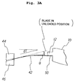
- the blades 42 are positioned at an angle 0, defined by the blade 42 and a plane orthogonal to the inner wall 32 of the cell body 24, such that when the blades are deformed by a desired fraction of the lens 10 weight, a tip portion 50 of the blade 42 is parallel to the surface of the ridge 12 on the lens 10. This is illustrated in Fig. 3A. A postion of the blade 42 is shown with a broken line in Fig. 3A when the lens 10 is not loaded into the cell 20.
- the bolts 48 also are utilized to mount the soft mounts 38 in the cutouts 36.
- the tip portion 50 of the blade 42 extends through the passageway 40 and forms a plurality of support members for the lens 10, in addition to the radial flexure mount seats 34.
- a set of the soft supports 38 are selected for distributing the gravitational load without overconstraining the lens.
- the soft supports include a set of nine (9) cantilever blades 42 for supporting a portion of the weight of the lens 10 in the optical axis direction.
- the cantilever blades 42 are compliant in the optical axis direction. Therefore, they do not overconstrain the lens positioning as determined by the three seats 34 on the radial flexure mounts 22. Instead, the blades 42 simply provide more distributed support of the lens 10 to counter any distortion due to gravity.
- An additional advantage of the soft mounts' compliance is the low sensitivity of supporting force to mechanical machining tolerances.
- the cell 20 is distorted, e.g., because it is pressed against a nonflat surface, the cell distortion will not cause a corresponding significant lens distortion. Specifically, even if cell distortion alters the location of one of the lens seats 34, because the lens 10 is not overconstrained in the optical direction, any resulting distortion of the lens 10 will be minimized.
- the soft mounts 38 should also be compliant in the radial direction to allow differential expansion.
- Cantilever springs are not compliant in the radial direction and can therefore create undesirable radial forces.
- the maximum undesirable force on the lens 10, however, is limited by the low contact force and the coefficient of friction between the cantilever spring tip 50 and the lens 10.
- Alternative soft mount springs are possible, including compressed or extended coil springs, magnets, or other suitable springs, which may or may not have radial compliance.
- the set of nine (9) soft mount blades 42 are evenly spaced in sets of three (3) between each of the three (3) radial flexure mounts 22, as illustrated in Fig 2A and diagrammatically in Fig. 4. This distributes the load and provides along with the seats 34 a nearly symmetrical lens support, with each blade 42 and each seat 34 designed to support one twelfth of the gravitational load of the lens 10.
- Other sets of soft supports 38 also could be utilized, such as three (3), six (6), or more, which can also be evenly spaced with the seats 34.
- the spring assembly 52 is illustrated in Figs. 3, 5, 6A-C and 7.
- the spring assembly 52 includes a spring member 54, best illustrated in the deformed state in Figs. 6A-C.
- the spring member 54 includes a first spring portion 56, which is designed to bow in one direction with a plurality of slots 58. The portion 56 is separated from a second oppositely bowed spring portion 60 by a longitudinal slot 62.
- the spring assembly 52 includes the member 54, a locator plate 64, a clamping block 66 and a spacer block 68.
- the plate 64 includes an aperture 70 for locating spacer block 68, a mounting aperture 72 and a locator slot 74 in an end 76.
- the spring member 54 and the block 66 include matching mounting apertures 78, 80.
- the block 66 further includes a depending locating portion 82, which bears against the member 54 and fits into the locator slot 74, when the spring assembly 52 is mounted onto the radial flexure mount 22.
- the locating portion 82 of the clamping block 66 fits into the locator slot 23 of the radial flexure mount.
- the spring assembly 52 is secured together and mounted with a bolt 84, such as a hex socket head bolt as illustrated.
- the spring assembly 52 is mounted utilizing the bolt 84 and an appropriate wrench 86, which is utilized to tighten the bolt into a threaded passageway 88 (Fig. 2B) in the radial flexure mount 22.
- an anti-torque tool 90 is engaged into a pair of apertures 92 (Figs. 2B and 2C) formed in the top of the radial flexure mount 22.
- the tool 90 includes a pair of arms 94, each of which include a pin or rod 96 which matches the apertures 92 and is engaged therein to prevent stress when the bolt 84 is tightened.
- the tool 90 includes a handle 98 from which the arms 94 extend and which is utilized to maintain the spring assembly 52 in the proper location during assembly and disassembly.
- FIG. 8 a second embodiment of an improved lens cell 100 of the present invention is illustrated.
- the cell 100 is very similar in overall structure to the cell 20 and the same numerals are utilized to indicate the same or functionally the same elements, describing in detail only the major differences in the cell 100 and the mounting structure thereof.
- the cell 100 has a plurality of radial flexure mounts 102, which are very similar to the radial flexure mounts 22, but are formed to support a different spring assembly 104.
- the spring assembly 104 is functionally similar to the spring assembly 52, however, the spring assembly 104 differs in structure as described below.
- the radial flexure mounts 102 include the lens seats 34 as before. Additionally, the radial flexure mount 102 and flexures 109, 110 are formed by a slot 106 in a cell body 108, as in the above described embodiment. In this second embodiment, however, a leaf-type clamping spring 116 provides the clamping force on the lens 10.
- the clamping spring assembly 104 includes an elongated clamping block 112, which has a notch 114 formed in one side thereof to accommodate the mounting and flexing of the leaf-type spring blade member 116.
- the spring member 116 is mounted into a second notch 118, which is formed in the bottom of the block 112 and extends beyond the notch 114.
- the spring member 116 resiliently biases a lens clamp block 120 having top and bottom arms 121, 123 to clamp the lens 10 (not illustrated) into the seat 34.
- the block 120 is slidingly engaged in an alignment slot 122, which is formed in the radial flexure mount 102.
- the clamping spring assembly 104 is mounted onto the radial flexure mount 102 utilizing a pair of bolts 84, which are threaded Into mating threaded passageways 88 formed in the top of the radial flexure mount 102. As shown in greater detail in Fig.
- the lens clamp block 120 has two slots 125 formed on an upper and lower surface of the top arm 121, which define a flexural hinge 127.
- the flexural hinge 127 allows a lens contacting surface 129 of the lens clamp block 120 to conform to the lens 10 when clamped, so that small variations in the mechanical dimensions of the lens 10 or the radial flexure mount 102 do not prevent surface contact of the clamp.
- the clamping spring assembly 104 again is mounted with the bolts 84, while aligned against torque stresses utilizing an antitorque tool 124.
- the tool 124 again has a pair of arms 126, 128, each of which include the depending rod 96, which again are engaged into the apertures 92 formed in the radial flexure mount 102.
- the tool 124 again substantially eliminates torque stresses during assembly and diassembly of the clamping spring assembly 104 on the radial flexure mount 102.
- the lens cell 100 also preferably includes a plurality of soft mounts 130, which are functionally equivalent to the soft mounts 38 described above with respect to the first embodiment.
- the mounts 130 include the blade 42, clamped by a pair of the bolts 48 inserted through a pair of dove-tailed blocks 132 and 134.
- One of the pair of blocks 134 includes a pair of end notches 136, 138 which are mated with a pair of complementary fingers 140, 142 formed on the other of the pair of blocks 132.
- the dove-tailed structure formed by the blocks 132, 134 insures that the blocks 132, 134 and blade spring 42 do not slip relative to each other when the bolts 48 are tightened.
- the present invention includes a mechanically clamped lens 10 which is constrained quasi-kinematically around the perimeter 16 of the lens.
- the cell 20 or 100 provides a three point mounting on small area seats 34 to avoid any substantial overconstraint of the lens 10 by the flat surface contact provided by the seats 34.
- Each of the seats 34 are part of the radial flexure mounts 22 or 102 which allow radial differential expansion of the lens 10, but which are stiff both vertically and tangentially to maintain a high mounting stiffness of the lens 10 which provides the desirable high frequency resonant modes.
- the spring assembly 52 or 104 mechanically clamps the lens 10 directly above the seats 34 to eliminate any potential moments caused by offsets between the clamp and seat forces.
- the problems inherent in adhesives of outgassing and destructive disassembly are avoided.
- the spring assembly 52 or 104 With the compliant clamping mechanism disclosed, the clamping force is applied substantially uniformly and constantly, despite some potential mechanical and dimensional differences due to mechanical tolerances.
- the clamping mechanisms are attached to the radial flexure mounts 22 or 102 to prevent overconstraint of the lens 10 due to differential expansion of the lens 10 and cell 20 or 100.
- each lens seat 34 can be provided on the inner wall 32 with the spring assembly 52 or 104 provided above the lens seat 34.
- the radial flexure mounts 22 or 102 function only to provide radial alignment.
- the addition of the soft mounts 38 or 130 to the support structure provided by the radial flexure mounts 22 and 102 further spreads the gravitational load from the three seats 34 to an additional number of points, preferably twelve as described.
- the applicants have analyzed the lens loading and have determined that the twelve peripheral support points on the lens 10 provide substantially optimum performance for prevention of gravity deformation.
- the blades 42 of the soft mounts 38 or 130 preferably are highly compliant cantilever-type springs formed from a flat material (e.g., metal, ceramic or other suitably flat material) of very precise thickness. The precise thickness minimizes the stiffness variation between the blades 42.
- any variation in thickness also can be compensated by varying the width of the blades 42 to maintain the desired uniformity in stiffness.
- the slots 26 and 106, as well as the blades 42 preferably are formed by utilizing wire electron discharge machining (EDM), which is very precise and does not create internal stresses in the material.
- EDM wire electron discharge machining
- the blades 42 could be replaced by coil springs or other types of biasing mechanisms (not illustrated).
- the lens mounting structure according to principles of the present invention is applicable in a photolithography system (exposure apparatus) such as a scanning type photolithography system which exposes a mask pattern on a substrate by moving a mask, held on a mask stage, and a substrate, held on a substrate stage, synchronously (see US Patent 5,473,410). Additionally, the present invention is applicable to a step-and-repeat type photolithography system that exposes a mask pattern while a mask and a substrate are stationary and moves the substrate in successive steps. Further, the present invention can also be applied to a proximity photolithography system that exposes a mask pattern by closely locating a mask and a substrate without the use of a projection optical system.
- a photolithography system need not be limited to a photolithography system in semiconductor manufacturing. For instance, it can be widely applied to an LCD photolithography system which exposes a liquid crystal display device pattern onto a rectangular glass plate and a photolithography system for manufacturing a thin film magnetic head.
- a light source for the photolithography system not only g-line (436 nm), i-line (365 nm), KrF excimer laser (248 nm), ArF excimer laser (193 nm) arid F 2 laser (157 nm) cart be used, but also charged particle beams such as x-ray and electron beam can be used.
- charged particle beams such as x-ray and electron beam
- thermionic emission type lanthanum hexaboride (LaB 6 ) or tantalum (Ta) can be used as an electron gun.
- the structure could be such that either a mask is used or a pattern can be directly formed on a substrate without the use of a mask.
- the system need not be limited to a reduction system. It could also be a 1x or magnification system.
- the optical system when far ultra-violet rays such as the excimer laser is used, glass materials such as quartz and fluorite that transmit far ultra-violet rays is preferable to be used.
- the optical system should preferably be either catadioptric or refractive (a reticle should also preferably be a reflective type), and when an electron beam is used, electron optics should preferably consist of electron lenses and deflectors. Needless to say, the optical path for the electron beams should be in a vacuum.
- the linear motors can be either an air levitation type employing air bearings or a magnetic levitation type using Lorentz force or reactance force.
- the stage could move along a guide, or it could be a guideless type stage which uses no guide.
- the stage could be driven by a planar motor, which drives the stage by electromagnetic force generated by a magnet unit having two-dimensionally arranged magnets and an armature coil unit having two-dimensionally arranged coils in facing positions.
- a planar motor which drives the stage by electromagnetic force generated by a magnet unit having two-dimensionally arranged magnets and an armature coil unit having two-dimensionally arranged coils in facing positions.
- reaction forces generated by the wafer (substrate) stage motion can be mechanically released to the floor (ground) by use of a frame member as described in US Patent 5,528,118 and published Japanese patent JP Hei 8-166475. Additionally, reaction forces generated by the reticle (mask) stage motion can be mechanically released to the floor (ground) by use of a frame member as described in US Patent 5,874,820 and published Japanese patent JP Hei 8-330224.
- a photolithography system can be built by assembling various subsystems, including each element listed in the appended claims, in such a manner that prescribed mechanical accuracy, electrical accuracy and optical accuracy are maintained.
- every optical system is adjusted to achieve its optical accuracy.
- every mechanical system and every electrical system are adjusted to achieve their respective mechanical and electrical accuracies.
- the process of assembling each subsystem into a photolithography system includes mechanical interfaces, electrical circuit wiring connections and air pressure plumbing connections between each subsystem. Needless to say, there is also a process where each subsystem is assembled prior to assembling a photolithography system from the various subsystems. Once a photolithography system is assembled using the various subsystems, total adjustment is performed to make sure that every accuracy is maintained in the complete photolithography system. Additionally, it is desirable to manufacture an exposure system in a clean room where the temperature and cleanliness are controlled.
- step 1201 the device's function and performance characteristics are designed.
- step 1202 a mask (reticle) having a pattern is designed according to the previous designing step, and in a parallel step 1203 a wafer is made from a silicon material.
- the mask pattern designed in step 1202 is exposed onto the wafer from step 1203 in step 1204 by a photolithography system described hereinabove in accordance with the present invention.
- step 1205 the semiconductor device is assembled (including the dicing process, bonding process and packaging process), then finally the device is inspected in step 1206.
Abstract
Description
- Fig. 1
- illustrates a cross section of one embodiment of a lens to be quasi-kinematically mounted in a cell in accordance with the present invention.
- Fig. 2A
- illustrates a perspective view of one embodiment of a cell for mounting the lens in accordance with the present invention.
- Fig. 2B
- illustrates an enlarged partial perspective view of the cell of Fig. 2A.
- Fig. 2C
- illustrates an enlarged top view of a radial flexure mount in accordance with the present invention.
- Fig. 3
- illustrates an exploded partial perspective view of the cell and supports of Fig 2A.
- Fig. 3A
- is an enlarged partial cross-sectional view illustrating the soft mount of Fig. 3 supporting a lens.
- Fig. 4
- illustrates a diagrammatic top view of the lens mounted in the cell by a plurality of soft supports along with three radial flexure lens supports.
- Fig. 5
- illustrates the operation of a tool utilized to mount the lens in the radial flexure supports without causing distortion.
- Figs. 6A-C
- illustrate one embodiment of a clamping spring which clamps the lens against the flexure supports.
- Fig. 7
- is an exploded perspective illustration of the clamping spring assembly.
- Fig. 8
- illustrates a second alternative embodiment of a lens cell.
- Figs. 9A and 9B
- are exploded partial views of the lens cell of Fig. 8, illustrating the assembly thereof.
- Fig. 10
- is an enlarged perspective view illustrating a second embodiment of a clamping spring assembly according to the present invention.
- Fig. 11
- is an enlarged side perspective view illustrating details of the lens clamp block shown in Fig. 10.
- Fig. 12
- is a flowchart showing a method for fabricating semiconductor devices by an apparatus according to the present invention.
Claims (13)
- A structure for mounting a lens (10), comprising:a lens cell member (20; 100) capable of holding the lens (10) around a periphery thereof;a plurality of radial flexure mounts (22; 102) affixed to the lens cell member (20; 100), each radial flexure mount including a pair of flexures (28, 30; 109, 110) extending at opposite ends of the radial flexure mount and a seat (34) affixed to the radial flexure mount for mounting the lens periphery;and a plurality of soft mounts (38; 130) disposed between adjacent radial flexure mounts, each soft mount including a resilient support (42) contacting the lens periphery to support at least part of the weight of the lens,
wherein ends of the pair of flexures (28, 30; 109, 110) are fixed to the lens cell member (20; 100) and the flexures can bend radially to accommodate expansion or contraction of the lens cell member due to temperature changes while minimizing stress on the lens. - The structure of claim 1, wherein the soft mounts (38; 130) include a cantilever blade member (42) resiliently supporting a portion of the weight of the lens (10) on the periphery thereof.
- The structure of claim 1, wherein the soft mounts include a spring member resiliently supporting a portion of the weight of the lens on the periphery thereof.
- The structure of any of the claims 1 to 3, wherein each seat (34) extends from a midpoint of the radial flexure mount (22; 102) such that the lens (10) rests against the seat at a location in the plane of the flexures (28, 30; 109, 110) so that axial motion of the lens does not exert adverse effects on the radial flexure mounts.
- The structure of any of the claims 1 to 4, wherein the radial flexure mounts (22; 102) include a spring assembly (52; 104) mounted thereon to resiliently clamp the lens (10) onto the seat (34).
- An exposure apparatus which transfers a pattern onto a substrate, the exposure apparatus including the lens mounting structure of any of the claims 1 to 5.
- A structure for mounting a lens comprising:a lens cell member (20; 100) capable of holding the lens (10);a plurality of radial flexure mounts (22; 102) integrally formed with the lens cell member (20; 100), each radial flexure mount having a seat (34) formed thereon for mounting the lens and a pair of flexures (28, 30; 109, 110) extending at opposite ends thereof;and a spring assembly (52; 104) mounted on each of the radial flexure mounts, each spring assembly including a compliant clamp (54; 116) for securing the lens on the seat,
wherein the flexures (28, 30; 109, 110) enable the radial flexure mounts (22; 102) to radially bend to accommodate expansion or contraction of the lens cell member (20; 100) due to temperature changes. - A structure for mounting a lens comprising:a lens cell member (22; 102) capable of holding the lens (10);and a plurality of soft mounts (38; 130) for supporting at least a portion of the weight of the lens, the soft mounts being compliant in the optical axis direction so that the structure is substantially insensitive to misalignment of the soft mounts in the optical axis direction.
- The structure of claim 8, wherein the soft mounts (38; 130) include a compliant structure (42) which bears against a periphery of the lens (10) and does not substantially constrain the lens in a radial direction of the lens.
- The structure of claim 9, wherein the compliant structure includes at least one spring member for supporting at least a portion of the weight of the lens.
- The structure of claim 9, wherein the compliant structure includes at least one cantilever blade (42) for supporting at least a portion of the weight of the lens.
- A method for assembling a structure for holding a lens (10), the structure including a lens cell member (20; 100), a radial flexure mount (22; 102) coupled to the lens cell member, a seat (34) formed on the radial flexure mount, a clamping assembly (52; 104) mounted on the radial flexure mount, the radial flexure mount (22; 102) including features for engaging a torque counteracting tool (90; 124), the method comprising:affixing the clamping assembly (52; 104) to the radial flexure mount (22; 102) by turning at least one threaded member (84) through the clamping assembly into the radial flexure mount; andsimultaneously engaging the torque counteracting tool (90; 124) with the radial flexure mount (22; 102) and applying a torque to the torque counteracting tool to counteract torque applied to the radial flexure mount by turning of thethreaded member (84).
- The method of claim 12, wherein the clamping assembly (52; 104) includes a spring member (54; 116) coupled to a clamping block (66; 112), the spring member urging the clamping block against the lens (10) to clamp the lens onto the seat.
Applications Claiming Priority (2)
| Application Number | Priority Date | Filing Date | Title |
|---|---|---|---|
| US09/386,255 US6239924B1 (en) | 1999-08-31 | 1999-08-31 | Kinematic lens mounting with distributed support and radial flexure |
| US386255 | 1999-08-31 |
Publications (3)
| Publication Number | Publication Date |
|---|---|
| EP1081521A2 true EP1081521A2 (en) | 2001-03-07 |
| EP1081521A3 EP1081521A3 (en) | 2004-01-02 |
| EP1081521B1 EP1081521B1 (en) | 2006-04-19 |
Family
ID=23524830
Family Applications (1)
| Application Number | Title | Priority Date | Filing Date |
|---|---|---|---|
| EP00116461A Expired - Lifetime EP1081521B1 (en) | 1999-08-31 | 2000-07-29 | Kinematic lens mounting |
Country Status (7)
| Country | Link |
|---|---|
| US (1) | US6239924B1 (en) |
| EP (1) | EP1081521B1 (en) |
| JP (1) | JP4622058B2 (en) |
| KR (1) | KR100654117B1 (en) |
| AT (1) | ATE323893T1 (en) |
| DE (1) | DE60027371T2 (en) |
| TW (1) | TW490599B (en) |
Cited By (21)
| Publication number | Priority date | Publication date | Assignee | Title |
|---|---|---|---|---|
| EP1179746A2 (en) * | 2000-08-10 | 2002-02-13 | Nikon Corporation | Kinematic optical mounting |
| WO2002016993A1 (en) * | 2000-08-18 | 2002-02-28 | Nikon Corporation | Optical element holding device |
| EP1308765A1 (en) * | 2001-11-06 | 2003-05-07 | Itt Manufacturing Enterprises, Inc. | Mount for ultra-high performance of optical components under thermal and vibrational distortion conditions |
| WO2003040785A1 (en) * | 2001-11-07 | 2003-05-15 | Nikon Corporation | Optical element, method of manufacturing the optical element, optical system, exposure device, and method of manufacturing micro device |
| WO2004001509A1 (en) * | 2002-06-20 | 2003-12-31 | Nikon Corporation | Adjustable soft mounts in kinematic mounting system for deformable lens |
| WO2004019104A1 (en) * | 2002-08-08 | 2004-03-04 | Carl Zeiss Smt Ag | Device for receiving an optical module in an imaging unit |
| EP1380899A3 (en) * | 2002-07-11 | 2004-12-29 | ASML Netherlands B.V. | Lithographic apparatus and device manufacturing method |
| EP1477853A3 (en) * | 2003-05-14 | 2006-05-03 | Canon Kabushiki Kaisha | Optical element holder, exposure apparatus, and device fabricating method |
| WO2006096045A1 (en) * | 2005-03-09 | 2006-09-14 | Stichting Astron | Suspension for keeping an object aligned during large temperature variations; optical system provided with such a suspension. |
| SG128443A1 (en) * | 2002-07-11 | 2007-01-30 | Asml Netherlands Bv | Lithographic apparatus and device manufacturing method |
| WO2007017013A2 (en) * | 2005-07-01 | 2007-02-15 | Carl Zeiss Smt Ag | Arrangement for mounting an optical component |
| WO2007020067A1 (en) * | 2005-08-16 | 2007-02-22 | Carl Zeiss Smt Ag | Immersion lithography objective |
| WO2009024192A1 (en) * | 2007-08-23 | 2009-02-26 | Carl Zeiss Smt Ag | Optical element module with minimized parasitic loads |
| WO2009083476A1 (en) * | 2007-12-27 | 2009-07-09 | Carl Zeiss Smt Ag | Optical device comprising a spring device with a range of constant spring force |
| CN103901571A (en) * | 2014-02-13 | 2014-07-02 | 中国科学院上海光学精密机械研究所 | Flexible supporting device and method for non-vertical placing of large transmission-reflection type lens |
| CN105371763A (en) * | 2015-12-01 | 2016-03-02 | 中国科学院长春光学精密机械与物理研究所 | Horizontal electromagnetic support device of large aperture optical component |
| WO2017218728A1 (en) * | 2016-06-17 | 2017-12-21 | Corning Incorporated | Polymer-free compliant optical member support |
| CN112068277A (en) * | 2020-08-31 | 2020-12-11 | 中国科学院长春光学精密机械与物理研究所 | Multistage flexible supporting structure of large-caliber optical lens |
| EP3789809A1 (en) * | 2019-09-03 | 2021-03-10 | ASML Netherlands B.V. | Assembly for collimating broadband radiation |
| EP3792673A1 (en) * | 2019-09-16 | 2021-03-17 | ASML Netherlands B.V. | Assembly for collimating broadband radiation |
| WO2022148569A1 (en) * | 2021-01-11 | 2022-07-14 | Carl Zeiss Smt Gmbh | Assembly having a decoupling joint for mechanically mounting an element |
Families Citing this family (64)
| Publication number | Priority date | Publication date | Assignee | Title |
|---|---|---|---|---|
| US6650412B1 (en) * | 1999-09-10 | 2003-11-18 | Kaiser Optical Systems | Thermal compensation for optical apparatus |
| WO2001075501A1 (en) * | 2000-03-31 | 2001-10-11 | Nikon Corporation | Method and device for holding optical member, optical device, exposure apparatus, and device manufacturing method |
| JP4945845B2 (en) * | 2000-03-31 | 2012-06-06 | 株式会社ニコン | An optical element holding device, a lens barrel, an exposure apparatus, and a microdevice manufacturing method. |
| US6473245B1 (en) | 2000-08-10 | 2002-10-29 | Nikon Corporation | Catadioptric lens barrel structure having a plurality of support platforms and method of making the same |
| US6577457B1 (en) | 2000-08-10 | 2003-06-10 | Nikon Corporation | Catadioptric lens barrel structure having a kinematic alignment structure and method for aligning two planar surfaces |
| US6639740B1 (en) | 2000-08-10 | 2003-10-28 | Nikon Corporation | Catadioptric lens barrel structure having a plurality of split lens barrels and a support structure supporting the split lens barrels |
| US6653639B1 (en) * | 2000-10-17 | 2003-11-25 | Nikon Corporation | Chuck for mounting reticle to a reticle stage |
| CN1227717C (en) * | 2000-11-10 | 2005-11-16 | 株式会社尼康 | Optical device, exposure device and device manufacturing method |
| US6439139B1 (en) * | 2000-11-17 | 2002-08-27 | Owens Corning Fiberglas Technology, Inc. | Method for recycling building materials |
| DE10100546A1 (en) * | 2001-01-08 | 2002-07-11 | Zeiss Carl | Device for adjusting an optical element in a lens |
| US6381081B1 (en) * | 2001-01-19 | 2002-04-30 | The United States Of America As Represented By The Administrator Of The National Aeronautics And Space Administration | Flexure-ring for centering a concave lens in a bore of a housing for an optical system |
| JP2002365013A (en) * | 2001-06-04 | 2002-12-18 | Fuji Photo Optical Co Ltd | Support device of reference plate for light wave interferometer |
| US6788389B2 (en) * | 2001-07-10 | 2004-09-07 | Nikon Corporation | Production method of projection optical system |
| US20030098965A1 (en) * | 2001-11-29 | 2003-05-29 | Mike Binnard | System and method for supporting a device holder with separate components |
| US6909493B2 (en) | 2002-03-20 | 2005-06-21 | Canon Kabushiki Kaisha | Correction member, retainer, exposure apparatus, and device fabrication method |
| AU2003231381A1 (en) * | 2002-04-22 | 2003-11-03 | Nikon Corporation | Support apparatus, optical apparatus, light exposure apparatus, and method for producing device |
| JP4333078B2 (en) * | 2002-04-26 | 2009-09-16 | 株式会社ニコン | Projection optical system, exposure apparatus including the projection optical system, exposure method using the projection optical system, and device manufacturing method |
| US7245361B2 (en) | 2002-06-04 | 2007-07-17 | Nikon Corporation | Method for evaluating refractive index homogeneity of optical member |
| JPWO2003102529A1 (en) * | 2002-06-04 | 2005-09-29 | 株式会社ニコン | Method for evaluating refractive index homogeneity of optical members |
| US20030235682A1 (en) * | 2002-06-21 | 2003-12-25 | Sogard Michael R. | Method and device for controlling thermal distortion in elements of a lithography system |
| US20030234916A1 (en) * | 2002-06-21 | 2003-12-25 | Nikon Corporation | Soft supports to reduce deformation of vertically mounted lens or mirror |
| US6922293B2 (en) * | 2002-07-02 | 2005-07-26 | Nikon Corporation | Kinematic optical mounting assembly with flexures |
| US6649865B1 (en) * | 2002-08-07 | 2003-11-18 | Great Computer Corp. | Control method for optical lens-seat on a laser processing machine |
| US20040080730A1 (en) * | 2002-10-29 | 2004-04-29 | Michael Binnard | System and method for clamping a device holder with reduced deformation |
| AU2003219097A1 (en) * | 2003-03-26 | 2004-10-18 | Carl Zeiss Smt Ag | Device for the low-deformation replaceable mounting of an optical element |
| JP2004347814A (en) * | 2003-05-21 | 2004-12-09 | Canon Inc | Holding device, exposure device, and device manufacturing method |
| KR101281357B1 (en) * | 2003-06-06 | 2013-07-02 | 가부시키가이샤 니콘 | Optical element holding device, lens barrel, exposing device, and device producing method |
| DE102004025832A1 (en) * | 2004-05-24 | 2005-12-22 | Carl Zeiss Smt Ag | Optics module for a lens |
| WO2005064382A1 (en) * | 2003-12-25 | 2005-07-14 | Nikon Corporation | Apparatus for holding optical element, barrel, exposure apparatus, and device producing method |
| EP1577693B1 (en) * | 2004-02-26 | 2011-07-13 | Carl Zeiss SMT GmbH | Objective comprising at least one optical element |
| DE102004014641B4 (en) * | 2004-03-09 | 2007-09-13 | Carl Zeiss Smt Ag | Arrangement for mounting an optical component |
| US20060238735A1 (en) * | 2005-04-22 | 2006-10-26 | Vladimir Kamenov | Optical system of a projection exposure apparatus |
| US20100033700A1 (en) * | 2005-06-14 | 2010-02-11 | Takaya Okada | Optical element, optical element holding device, exposure apparatus, and device manufacturing method |
| TWI372271B (en) * | 2005-09-13 | 2012-09-11 | Zeiss Carl Smt Gmbh | Optical element unit, optical element holder, method of manufacturing an optical element holder, optical element module, optical exposure apparatus, and method of manufacturing a semiconductor device |
| WO2007132862A1 (en) * | 2006-05-16 | 2007-11-22 | Nikon Corporation | Projection optical system, exposure method, exposure apparatus, and method for manufacturing device |
| EP2444829A1 (en) | 2006-09-14 | 2012-04-25 | Carl Zeiss SMT GmbH | Optical element unit and method of supporting an optical element |
| US8416386B2 (en) * | 2007-03-13 | 2013-04-09 | Nikon Corporation | Conforming seats for clamps used in mounting an optical element, and optical systems comprising same |
| WO2008146655A1 (en) * | 2007-05-25 | 2008-12-04 | Nikon Corporation | Optical element holding apparatus, lens barrel, exposure apparatus and device manufacturing method |
| US7990628B1 (en) * | 2007-08-29 | 2011-08-02 | Tessera MEMS Technologies, Inc. | Planar flexure system with high pitch stiffness |
| DE102007047186B4 (en) * | 2007-10-02 | 2014-01-09 | Carl Zeiss Sms Gmbh | Recording device for receiving a photolithography mask |
| DE102008022211B3 (en) * | 2008-05-06 | 2010-02-25 | Carl Zeiss Surgical Gmbh | Lens carrier for receiving lens element i.e. ophthalmoscopic magnifying glass, in operating microscope, has lens holder having different axial thicknesses in region outside retaining elements and in holding region of retaining elements |
| JP2011528859A (en) * | 2008-07-21 | 2011-11-24 | エーエスエムエル ネザーランズ ビー.ブイ. | Optical element mount for lithographic apparatus |
| US8591048B2 (en) * | 2009-10-30 | 2013-11-26 | Flir Systems, Inc. | Spatially efficient kinematic mirror mount |
| US8919724B2 (en) | 2010-08-24 | 2014-12-30 | Raytheon Company | Mount for cryogenic fast switching mechanism |
| CN102486564B (en) * | 2010-12-06 | 2014-10-29 | 上海微电子装备有限公司 | Lens flexibility fixing device |
| CN102243359B (en) * | 2011-06-20 | 2012-11-14 | 北京空间机电研究所 | Flexible supporting method of large-aperture lens |
| JP5695011B2 (en) * | 2012-10-31 | 2015-04-01 | カール・ツァイス・エスエムティー・ゲーエムベーハー | Parasitic load minimizing optical element module |
| DE202013011933U1 (en) | 2013-01-23 | 2014-10-28 | Jenoptik Optical Systems Gmbh | Thermally compensated optical assembly with a form-fitting held optical component |
| CN103885302B (en) * | 2014-04-04 | 2016-03-30 | 中国科学院光电技术研究所 | A kind of accurate bracing or strutting arrangement of force feedback of the optical element that is installed |
| JP5848470B2 (en) * | 2015-02-05 | 2016-01-27 | カール・ツァイス・エスエムティー・ゲーエムベーハー | Parasitic load minimizing optical element module |
| CN106383395A (en) * | 2015-07-29 | 2017-02-08 | 上海微电子装备有限公司 | Large-diameter side vertical mirror group structure |
| CN107329225B (en) * | 2016-04-29 | 2020-06-16 | 上海微电子装备(集团)股份有限公司 | Side standing lens group and mounting method thereof |
| US10015378B2 (en) | 2016-09-15 | 2018-07-03 | Microsoft Technology Licensing, Llc | Kinematic mount for split camera |
| TWI597536B (en) | 2016-10-27 | 2017-09-01 | 財團法人國家實驗硏究院 | Supporting device and method for supporting lens and supporting component for supporting functional element |
| US10678018B2 (en) * | 2017-10-23 | 2020-06-09 | Magna Electronics Inc. | Camera for vehicle vision system with replaceable lens |
| EP3759537B1 (en) * | 2018-03-02 | 2023-07-19 | Gooch And Housego PLC | Mounting ring for maintaining optical device alignment |
| GB201804952D0 (en) * | 2018-03-27 | 2018-05-09 | Pxyl Ltd | Improved scanning optical microscope |
| US11692816B2 (en) | 2018-04-27 | 2023-07-04 | Cognex Corporation | Mounting arrangement for optical systems |
| EP3608627B1 (en) | 2018-08-09 | 2023-11-08 | Cognex Corporation | Positioning system for components of optical systems |
| CN109387918A (en) * | 2018-12-03 | 2019-02-26 | 长春奥普光电技术股份有限公司 | A kind of three integrated mirror positioning combined device of master and method |
| CN110568576B (en) * | 2019-09-09 | 2021-04-06 | 中国科学院长春光学精密机械与物理研究所 | Flexible lens supporting device |
| CN112128546B (en) * | 2020-09-30 | 2021-11-05 | 中国科学院国家天文台南京天文光学技术研究所 | Support structure for large-size spliced optical element and mounting method thereof |
| CN113917645B (en) * | 2021-11-01 | 2023-03-31 | 中国科学院光电技术研究所 | Lens elastic supporting device |
| CN114486939B (en) * | 2022-04-08 | 2022-07-22 | 欧普康视科技股份有限公司 | Lens scratch detection system and method |
Citations (6)
| Publication number | Priority date | Publication date | Assignee | Title |
|---|---|---|---|---|
| US2808762A (en) * | 1956-06-25 | 1957-10-08 | Bausch & Lomb | Lens mounting means |
| DE1262041B (en) * | 1965-07-13 | 1968-02-29 | Voigtlaender Ag | Holder for lenses |
| JPS58159509A (en) * | 1982-03-18 | 1983-09-21 | Olympus Optical Co Ltd | Lens holding device |
| JPS58187907A (en) * | 1982-04-27 | 1983-11-02 | Olympus Optical Co Ltd | Lens holding device |
| US4733945A (en) * | 1986-01-15 | 1988-03-29 | The Perkin-Elmer Corporation | Precision lens mounting |
| EP1026532A1 (en) * | 1999-02-03 | 2000-08-09 | Carl Zeiss | Assembly comprising an optical element and an optical mount |
Family Cites Families (8)
| Publication number | Priority date | Publication date | Assignee | Title |
|---|---|---|---|---|
| US2937571A (en) | 1957-10-08 | 1960-05-24 | Ernest B Thompson | Optical lens mount |
| US3601343A (en) | 1969-09-05 | 1971-08-24 | North American Rockwell | Strain-free mount |
| US4929054A (en) | 1986-04-28 | 1990-05-29 | The Perkin-Elmer Corporation | Mounting for high resolution projection lenses |
| US4726671A (en) | 1986-06-19 | 1988-02-23 | The Perkin-Elmer Corporation | High resonance adjustable mirror mount |
| US5428482A (en) * | 1991-11-04 | 1995-06-27 | General Signal Corporation | Decoupled mount for optical element and stacked annuli assembly |
| JP3412638B2 (en) * | 1993-01-19 | 2003-06-03 | 株式会社ニコン | Lens holder |
| JPH06250061A (en) * | 1993-02-26 | 1994-09-09 | Nikon Corp | Optical member holding device |
| JP3956454B2 (en) | 1997-11-18 | 2007-08-08 | 株式会社ニコン | Lens support apparatus, support method, and projection exposure apparatus |
-
1999
- 1999-08-31 US US09/386,255 patent/US6239924B1/en not_active Expired - Lifetime
-
2000
- 2000-03-21 TW TW089105120A patent/TW490599B/en not_active IP Right Cessation
- 2000-05-26 KR KR1020000028700A patent/KR100654117B1/en active IP Right Grant
- 2000-07-11 JP JP2000210029A patent/JP4622058B2/en not_active Expired - Lifetime
- 2000-07-29 EP EP00116461A patent/EP1081521B1/en not_active Expired - Lifetime
- 2000-07-29 DE DE60027371T patent/DE60027371T2/en not_active Expired - Fee Related
- 2000-07-29 AT AT00116461T patent/ATE323893T1/en not_active IP Right Cessation
Patent Citations (6)
| Publication number | Priority date | Publication date | Assignee | Title |
|---|---|---|---|---|
| US2808762A (en) * | 1956-06-25 | 1957-10-08 | Bausch & Lomb | Lens mounting means |
| DE1262041B (en) * | 1965-07-13 | 1968-02-29 | Voigtlaender Ag | Holder for lenses |
| JPS58159509A (en) * | 1982-03-18 | 1983-09-21 | Olympus Optical Co Ltd | Lens holding device |
| JPS58187907A (en) * | 1982-04-27 | 1983-11-02 | Olympus Optical Co Ltd | Lens holding device |
| US4733945A (en) * | 1986-01-15 | 1988-03-29 | The Perkin-Elmer Corporation | Precision lens mounting |
| EP1026532A1 (en) * | 1999-02-03 | 2000-08-09 | Carl Zeiss | Assembly comprising an optical element and an optical mount |
Non-Patent Citations (2)
| Title |
|---|
| PATENT ABSTRACTS OF JAPAN vol. 007, no. 286 (P-244), 21 December 1983 (1983-12-21) -& JP 58 159509 A (OLYMPUS KOGAKU KOGYO KK), 21 September 1983 (1983-09-21) * |
| PATENT ABSTRACTS OF JAPAN vol. 008, no. 033 (P-254), 14 February 1984 (1984-02-14) -& JP 58 187907 A (OLYMPUS KOGAKU KOGYO KK), 2 November 1983 (1983-11-02) * |
Cited By (38)
| Publication number | Priority date | Publication date | Assignee | Title |
|---|---|---|---|---|
| EP1179746A3 (en) * | 2000-08-10 | 2004-06-09 | Nikon Corporation | Kinematic optical mounting |
| EP1179746A2 (en) * | 2000-08-10 | 2002-02-13 | Nikon Corporation | Kinematic optical mounting |
| US7420752B2 (en) | 2000-08-18 | 2008-09-02 | Nikon Corporation | Holding apparatus |
| WO2002016993A1 (en) * | 2000-08-18 | 2002-02-28 | Nikon Corporation | Optical element holding device |
| KR100775796B1 (en) * | 2000-08-18 | 2007-11-12 | 가부시키가이샤 니콘 | Optical element holding device |
| US7154684B2 (en) | 2000-08-18 | 2006-12-26 | Nikon Corporation | Optical element holding apparatus |
| EP1308765A1 (en) * | 2001-11-06 | 2003-05-07 | Itt Manufacturing Enterprises, Inc. | Mount for ultra-high performance of optical components under thermal and vibrational distortion conditions |
| WO2003040785A1 (en) * | 2001-11-07 | 2003-05-15 | Nikon Corporation | Optical element, method of manufacturing the optical element, optical system, exposure device, and method of manufacturing micro device |
| WO2004001509A1 (en) * | 2002-06-20 | 2003-12-31 | Nikon Corporation | Adjustable soft mounts in kinematic mounting system for deformable lens |
| US7554105B2 (en) | 2002-07-11 | 2009-06-30 | Asml Netherlands B.V. | Lithographic apparatus and device manufacturing method |
| EP1380899A3 (en) * | 2002-07-11 | 2004-12-29 | ASML Netherlands B.V. | Lithographic apparatus and device manufacturing method |
| SG128443A1 (en) * | 2002-07-11 | 2007-01-30 | Asml Netherlands Bv | Lithographic apparatus and device manufacturing method |
| CN100401193C (en) * | 2002-07-11 | 2008-07-09 | Asml荷兰有限公司 | Method for producing photoetching apparatus and parts |
| WO2004019104A1 (en) * | 2002-08-08 | 2004-03-04 | Carl Zeiss Smt Ag | Device for receiving an optical module in an imaging unit |
| EP1477853A3 (en) * | 2003-05-14 | 2006-05-03 | Canon Kabushiki Kaisha | Optical element holder, exposure apparatus, and device fabricating method |
| WO2006096045A1 (en) * | 2005-03-09 | 2006-09-14 | Stichting Astron | Suspension for keeping an object aligned during large temperature variations; optical system provided with such a suspension. |
| WO2007017013A3 (en) * | 2005-07-01 | 2008-05-02 | Zeiss Carl Smt Ag | Arrangement for mounting an optical component |
| WO2007017013A2 (en) * | 2005-07-01 | 2007-02-15 | Carl Zeiss Smt Ag | Arrangement for mounting an optical component |
| US7920344B2 (en) | 2005-07-01 | 2011-04-05 | Carl Zeiss Smt Gmbh | Arrangement for mounting an optical element |
| WO2007020067A1 (en) * | 2005-08-16 | 2007-02-22 | Carl Zeiss Smt Ag | Immersion lithography objective |
| US7649702B2 (en) | 2005-08-16 | 2010-01-19 | Carl Zeiss Smt Ag | Immersion lithography objective |
| WO2009024192A1 (en) * | 2007-08-23 | 2009-02-26 | Carl Zeiss Smt Ag | Optical element module with minimized parasitic loads |
| US8351139B2 (en) | 2007-08-23 | 2013-01-08 | Carl Zeiss Smt Gmbh | Optical element module with minimized parasitic loads |
| US10215948B2 (en) | 2007-08-23 | 2019-02-26 | Carl Zeiss Smt Gmbh | Optical element module with minimized parasitic loads |
| WO2009083476A1 (en) * | 2007-12-27 | 2009-07-09 | Carl Zeiss Smt Ag | Optical device comprising a spring device with a range of constant spring force |
| CN103901571A (en) * | 2014-02-13 | 2014-07-02 | 中国科学院上海光学精密机械研究所 | Flexible supporting device and method for non-vertical placing of large transmission-reflection type lens |
| CN103901571B (en) * | 2014-02-13 | 2016-03-09 | 中国科学院上海光学精密机械研究所 | The flexible support device of the non-perpendicular placement of large-scale Transflective eyeglass and method for supporting |
| CN105371763A (en) * | 2015-12-01 | 2016-03-02 | 中国科学院长春光学精密机械与物理研究所 | Horizontal electromagnetic support device of large aperture optical component |
| CN105371763B (en) * | 2015-12-01 | 2017-09-19 | 中国科学院长春光学精密机械与物理研究所 | A kind of horizontal electromagnetic supporting device of optical elements of large caliber |
| WO2017218728A1 (en) * | 2016-06-17 | 2017-12-21 | Corning Incorporated | Polymer-free compliant optical member support |
| CN114303102A (en) * | 2019-09-03 | 2022-04-08 | Asml荷兰有限公司 | Assembly for collimating broadband radiation |
| EP3789809A1 (en) * | 2019-09-03 | 2021-03-10 | ASML Netherlands B.V. | Assembly for collimating broadband radiation |
| WO2021043516A1 (en) * | 2019-09-03 | 2021-03-11 | Asml Netherlands B.V. | Assembly for collimating broadband radiation |
| TWI768445B (en) * | 2019-09-03 | 2022-06-21 | 荷蘭商Asml荷蘭公司 | Assembly for collimating broadband radiation and related radiation source, convex refractive singlet lens, inspection apparatus, and lithographic apparatus |
| US11619887B2 (en) | 2019-09-03 | 2023-04-04 | Asml Netherlands B.V. | Assembly for collimating broadband radiation |
| EP3792673A1 (en) * | 2019-09-16 | 2021-03-17 | ASML Netherlands B.V. | Assembly for collimating broadband radiation |
| CN112068277A (en) * | 2020-08-31 | 2020-12-11 | 中国科学院长春光学精密机械与物理研究所 | Multistage flexible supporting structure of large-caliber optical lens |
| WO2022148569A1 (en) * | 2021-01-11 | 2022-07-14 | Carl Zeiss Smt Gmbh | Assembly having a decoupling joint for mechanically mounting an element |
Also Published As
| Publication number | Publication date |
|---|---|
| JP4622058B2 (en) | 2011-02-02 |
| TW490599B (en) | 2002-06-11 |
| US6239924B1 (en) | 2001-05-29 |
| EP1081521B1 (en) | 2006-04-19 |
| JP2001074991A (en) | 2001-03-23 |
| KR20010020912A (en) | 2001-03-15 |
| EP1081521A3 (en) | 2004-01-02 |
| DE60027371D1 (en) | 2006-05-24 |
| ATE323893T1 (en) | 2006-05-15 |
| DE60027371T2 (en) | 2007-06-21 |
| KR100654117B1 (en) | 2006-12-05 |
Similar Documents
| Publication | Publication Date | Title |
|---|---|---|
| US6239924B1 (en) | Kinematic lens mounting with distributed support and radial flexure | |
| US7113263B2 (en) | Supporting structure of optical element, exposure apparatus having the same, and manufacturing method of semiconductor device | |
| EP1376183A2 (en) | Optical-element mountings exhibiting reduced deformation of optical elements held thereby | |
| US7345834B2 (en) | Optical element holding system, barrel, exposure apparatus, and device manufacturing method | |
| US6400516B1 (en) | Kinematic optical mounting | |
| US8416386B2 (en) | Conforming seats for clamps used in mounting an optical element, and optical systems comprising same | |
| US6574053B1 (en) | Kinematic alignment structure for placement between components axially aligned in a cylindrical body | |
| US6922293B2 (en) | Kinematic optical mounting assembly with flexures | |
| US7218462B2 (en) | Holding mechanism, optical apparatus and device manufacturing method | |
| US9557560B2 (en) | Mirror unit and exposure apparatus | |
| WO2004001509A1 (en) | Adjustable soft mounts in kinematic mounting system for deformable lens | |
| US8508870B2 (en) | Supporting device, optical apparatus, exposure apparatus, and device manufacturing method | |
| US7061577B2 (en) | Image adjustor including damping assembly | |
| US20040080730A1 (en) | System and method for clamping a device holder with reduced deformation | |
| JP2013106017A (en) | Optical element holding device, optical device, and exposure device | |
| US20030098965A1 (en) | System and method for supporting a device holder with separate components | |
| JP4956680B2 (en) | Support structure for optical element, exposure apparatus using the same, and method for manufacturing semiconductor device | |
| US20030030778A1 (en) | Vacuum compatible air bearing stage | |
| JP2004093663A (en) | Supporting means of optical element, optical apparatus such as optical system by supporting means of optical element and aligner, and device manufacturing method | |
| CN115729054A (en) | Driving device, exposure device, and article manufacturing method |
Legal Events
| Date | Code | Title | Description |
|---|---|---|---|
| PUAI | Public reference made under article 153(3) epc to a published international application that has entered the european phase |
Free format text: ORIGINAL CODE: 0009012 |
|
| AK | Designated contracting states |
Kind code of ref document: A2 Designated state(s): AT BE CH CY DE DK ES FI FR GB GR IE IT LI LU MC NL PT SE |
|
| AX | Request for extension of the european patent |
Free format text: AL;LT;LV;MK;RO;SI |
|
| PUAL | Search report despatched |
Free format text: ORIGINAL CODE: 0009013 |
|
| AK | Designated contracting states |
Kind code of ref document: A3 Designated state(s): AT BE CH CY DE DK ES FI FR GB GR IE IT LI LU MC NL PT SE |
|
| AX | Request for extension of the european patent |
Extension state: AL LT LV MK RO SI |
|
| 17P | Request for examination filed |
Effective date: 20040429 |
|
| AKX | Designation fees paid |
Designated state(s): AT BE CH CY DE DK ES FI FR GB GR IE IT LI LU MC NL PT SE |
|
| 17Q | First examination report despatched |
Effective date: 20041018 |
|
| GRAP | Despatch of communication of intention to grant a patent |
Free format text: ORIGINAL CODE: EPIDOSNIGR1 |
|
| GRAS | Grant fee paid |
Free format text: ORIGINAL CODE: EPIDOSNIGR3 |
|
| GRAA | (expected) grant |
Free format text: ORIGINAL CODE: 0009210 |
|
| AK | Designated contracting states |
Kind code of ref document: B1 Designated state(s): AT BE CH CY DE DK ES FI FR GB GR IE IT LI LU MC NL PT SE |
|
| PG25 | Lapsed in a contracting state [announced via postgrant information from national office to epo] |
Ref country code: IT Free format text: LAPSE BECAUSE OF FAILURE TO SUBMIT A TRANSLATION OF THE DESCRIPTION OR TO PAY THE FEE WITHIN THE PRESCRIBED TIME-LIMIT;WARNING: LAPSES OF ITALIAN PATENTS WITH EFFECTIVE DATE BEFORE 2007 MAY HAVE OCCURRED AT ANY TIME BEFORE 2007. THE CORRECT EFFECTIVE DATE MAY BE DIFFERENT FROM THE ONE RECORDED. Effective date: 20060419 Ref country code: LI Free format text: LAPSE BECAUSE OF FAILURE TO SUBMIT A TRANSLATION OF THE DESCRIPTION OR TO PAY THE FEE WITHIN THE PRESCRIBED TIME-LIMIT Effective date: 20060419 Ref country code: AT Free format text: LAPSE BECAUSE OF FAILURE TO SUBMIT A TRANSLATION OF THE DESCRIPTION OR TO PAY THE FEE WITHIN THE PRESCRIBED TIME-LIMIT Effective date: 20060419 Ref country code: FI Free format text: LAPSE BECAUSE OF FAILURE TO SUBMIT A TRANSLATION OF THE DESCRIPTION OR TO PAY THE FEE WITHIN THE PRESCRIBED TIME-LIMIT Effective date: 20060419 Ref country code: BE Free format text: LAPSE BECAUSE OF FAILURE TO SUBMIT A TRANSLATION OF THE DESCRIPTION OR TO PAY THE FEE WITHIN THE PRESCRIBED TIME-LIMIT Effective date: 20060419 Ref country code: CH Free format text: LAPSE BECAUSE OF FAILURE TO SUBMIT A TRANSLATION OF THE DESCRIPTION OR TO PAY THE FEE WITHIN THE PRESCRIBED TIME-LIMIT Effective date: 20060419 |
|
| REG | Reference to a national code |
Ref country code: GB Ref legal event code: FG4D |
|
| REF | Corresponds to: |
Ref document number: 60027371 Country of ref document: DE Date of ref document: 20060524 Kind code of ref document: P |
|
| REG | Reference to a national code |
Ref country code: IE Ref legal event code: FG4D |
|
| PG25 | Lapsed in a contracting state [announced via postgrant information from national office to epo] |
Ref country code: DK Free format text: LAPSE BECAUSE OF FAILURE TO SUBMIT A TRANSLATION OF THE DESCRIPTION OR TO PAY THE FEE WITHIN THE PRESCRIBED TIME-LIMIT Effective date: 20060719 Ref country code: SE Free format text: LAPSE BECAUSE OF FAILURE TO SUBMIT A TRANSLATION OF THE DESCRIPTION OR TO PAY THE FEE WITHIN THE PRESCRIBED TIME-LIMIT Effective date: 20060719 |
|
| PG25 | Lapsed in a contracting state [announced via postgrant information from national office to epo] |
Ref country code: GB Free format text: LAPSE BECAUSE OF NON-PAYMENT OF DUE FEES Effective date: 20060729 |
|
| PG25 | Lapsed in a contracting state [announced via postgrant information from national office to epo] |
Ref country code: ES Free format text: LAPSE BECAUSE OF FAILURE TO SUBMIT A TRANSLATION OF THE DESCRIPTION OR TO PAY THE FEE WITHIN THE PRESCRIBED TIME-LIMIT Effective date: 20060730 |
|
| PG25 | Lapsed in a contracting state [announced via postgrant information from national office to epo] |
Ref country code: MC Free format text: LAPSE BECAUSE OF NON-PAYMENT OF DUE FEES Effective date: 20060731 Ref country code: IE Free format text: LAPSE BECAUSE OF NON-PAYMENT OF DUE FEES Effective date: 20060731 |
|
| PG25 | Lapsed in a contracting state [announced via postgrant information from national office to epo] |
Ref country code: PT Free format text: LAPSE BECAUSE OF FAILURE TO SUBMIT A TRANSLATION OF THE DESCRIPTION OR TO PAY THE FEE WITHIN THE PRESCRIBED TIME-LIMIT Effective date: 20060919 |
|
| REG | Reference to a national code |
Ref country code: CH Ref legal event code: PL |
|
| PLBE | No opposition filed within time limit |
Free format text: ORIGINAL CODE: 0009261 |
|
| STAA | Information on the status of an ep patent application or granted ep patent |
Free format text: STATUS: NO OPPOSITION FILED WITHIN TIME LIMIT |
|
| 26N | No opposition filed |
Effective date: 20070122 |
|
| GBPC | Gb: european patent ceased through non-payment of renewal fee |
Effective date: 20060729 |
|
| EN | Fr: translation not filed | ||
| PG25 | Lapsed in a contracting state [announced via postgrant information from national office to epo] |
Ref country code: GR Free format text: LAPSE BECAUSE OF FAILURE TO SUBMIT A TRANSLATION OF THE DESCRIPTION OR TO PAY THE FEE WITHIN THE PRESCRIBED TIME-LIMIT Effective date: 20060720 Ref country code: FR Free format text: LAPSE BECAUSE OF FAILURE TO SUBMIT A TRANSLATION OF THE DESCRIPTION OR TO PAY THE FEE WITHIN THE PRESCRIBED TIME-LIMIT Effective date: 20070309 |
|
| PG25 | Lapsed in a contracting state [announced via postgrant information from national office to epo] |
Ref country code: LU Free format text: LAPSE BECAUSE OF NON-PAYMENT OF DUE FEES Effective date: 20060729 |
|
| PG25 | Lapsed in a contracting state [announced via postgrant information from national office to epo] |
Ref country code: FR Free format text: LAPSE BECAUSE OF FAILURE TO SUBMIT A TRANSLATION OF THE DESCRIPTION OR TO PAY THE FEE WITHIN THE PRESCRIBED TIME-LIMIT Effective date: 20060419 Ref country code: CY Free format text: LAPSE BECAUSE OF FAILURE TO SUBMIT A TRANSLATION OF THE DESCRIPTION OR TO PAY THE FEE WITHIN THE PRESCRIBED TIME-LIMIT Effective date: 20060419 |
|
| PGFP | Annual fee paid to national office [announced via postgrant information from national office to epo] |
Ref country code: NL Payment date: 20080715 Year of fee payment: 9 |
|
| PGFP | Annual fee paid to national office [announced via postgrant information from national office to epo] |
Ref country code: DE Payment date: 20081030 Year of fee payment: 9 |
|
| NLV4 | Nl: lapsed or anulled due to non-payment of the annual fee |
Effective date: 20100201 |
|
| PG25 | Lapsed in a contracting state [announced via postgrant information from national office to epo] |
Ref country code: DE Free format text: LAPSE BECAUSE OF NON-PAYMENT OF DUE FEES Effective date: 20100202 |
|
| PG25 | Lapsed in a contracting state [announced via postgrant information from national office to epo] |
Ref country code: NL Free format text: LAPSE BECAUSE OF NON-PAYMENT OF DUE FEES Effective date: 20100201 |