EP1083390A2 - Air conditioner having dehumidifying and ventilating functions - Google Patents
Air conditioner having dehumidifying and ventilating functions Download PDFInfo
- Publication number
- EP1083390A2 EP1083390A2 EP00119509A EP00119509A EP1083390A2 EP 1083390 A2 EP1083390 A2 EP 1083390A2 EP 00119509 A EP00119509 A EP 00119509A EP 00119509 A EP00119509 A EP 00119509A EP 1083390 A2 EP1083390 A2 EP 1083390A2
- Authority
- EP
- European Patent Office
- Prior art keywords
- moisture
- air conditioner
- indoor
- humidifying
- dehumidifying
- Prior art date
- Legal status (The legal status is an assumption and is not a legal conclusion. Google has not performed a legal analysis and makes no representation as to the accuracy of the status listed.)
- Withdrawn
Links
Images


Classifications
-
- F—MECHANICAL ENGINEERING; LIGHTING; HEATING; WEAPONS; BLASTING
- F24—HEATING; RANGES; VENTILATING
- F24F—AIR-CONDITIONING; AIR-HUMIDIFICATION; VENTILATION; USE OF AIR CURRENTS FOR SCREENING
- F24F3/00—Air-conditioning systems in which conditioned primary air is supplied from one or more central stations to distributing units in the rooms or spaces where it may receive secondary treatment; Apparatus specially designed for such systems
- F24F3/12—Air-conditioning systems in which conditioned primary air is supplied from one or more central stations to distributing units in the rooms or spaces where it may receive secondary treatment; Apparatus specially designed for such systems characterised by the treatment of the air otherwise than by heating and cooling
- F24F3/14—Air-conditioning systems in which conditioned primary air is supplied from one or more central stations to distributing units in the rooms or spaces where it may receive secondary treatment; Apparatus specially designed for such systems characterised by the treatment of the air otherwise than by heating and cooling by humidification; by dehumidification
- F24F3/1411—Air-conditioning systems in which conditioned primary air is supplied from one or more central stations to distributing units in the rooms or spaces where it may receive secondary treatment; Apparatus specially designed for such systems characterised by the treatment of the air otherwise than by heating and cooling by humidification; by dehumidification by absorbing or adsorbing water, e.g. using an hygroscopic desiccant
- F24F3/1423—Air-conditioning systems in which conditioned primary air is supplied from one or more central stations to distributing units in the rooms or spaces where it may receive secondary treatment; Apparatus specially designed for such systems characterised by the treatment of the air otherwise than by heating and cooling by humidification; by dehumidification by absorbing or adsorbing water, e.g. using an hygroscopic desiccant with a moving bed of solid desiccants, e.g. a rotary wheel supporting solid desiccants
-
- F—MECHANICAL ENGINEERING; LIGHTING; HEATING; WEAPONS; BLASTING
- F24—HEATING; RANGES; VENTILATING
- F24F—AIR-CONDITIONING; AIR-HUMIDIFICATION; VENTILATION; USE OF AIR CURRENTS FOR SCREENING
- F24F1/00—Room units for air-conditioning, e.g. separate or self-contained units or units receiving primary air from a central station
- F24F1/0007—Indoor units, e.g. fan coil units
- F24F1/0071—Indoor units, e.g. fan coil units with means for purifying supplied air
-
- F—MECHANICAL ENGINEERING; LIGHTING; HEATING; WEAPONS; BLASTING
- F24—HEATING; RANGES; VENTILATING
- F24F—AIR-CONDITIONING; AIR-HUMIDIFICATION; VENTILATION; USE OF AIR CURRENTS FOR SCREENING
- F24F11/00—Control or safety arrangements
- F24F11/0001—Control or safety arrangements for ventilation
-
- F—MECHANICAL ENGINEERING; LIGHTING; HEATING; WEAPONS; BLASTING
- F24—HEATING; RANGES; VENTILATING
- F24F—AIR-CONDITIONING; AIR-HUMIDIFICATION; VENTILATION; USE OF AIR CURRENTS FOR SCREENING
- F24F11/00—Control or safety arrangements
- F24F11/62—Control or safety arrangements characterised by the type of control or by internal processing, e.g. using fuzzy logic, adaptive control or estimation of values
- F24F11/63—Electronic processing
- F24F11/65—Electronic processing for selecting an operating mode
-
- F—MECHANICAL ENGINEERING; LIGHTING; HEATING; WEAPONS; BLASTING
- F24—HEATING; RANGES; VENTILATING
- F24F—AIR-CONDITIONING; AIR-HUMIDIFICATION; VENTILATION; USE OF AIR CURRENTS FOR SCREENING
- F24F11/00—Control or safety arrangements
- F24F11/30—Control or safety arrangements for purposes related to the operation of the system, e.g. for safety or monitoring
-
- F—MECHANICAL ENGINEERING; LIGHTING; HEATING; WEAPONS; BLASTING
- F24—HEATING; RANGES; VENTILATING
- F24F—AIR-CONDITIONING; AIR-HUMIDIFICATION; VENTILATION; USE OF AIR CURRENTS FOR SCREENING
- F24F2110/00—Control inputs relating to air properties
- F24F2110/20—Humidity
-
- F—MECHANICAL ENGINEERING; LIGHTING; HEATING; WEAPONS; BLASTING
- F24—HEATING; RANGES; VENTILATING
- F24F—AIR-CONDITIONING; AIR-HUMIDIFICATION; VENTILATION; USE OF AIR CURRENTS FOR SCREENING
- F24F2203/00—Devices or apparatus used for air treatment
- F24F2203/10—Rotary wheel
- F24F2203/1012—Details of the casing or cover
-
- F—MECHANICAL ENGINEERING; LIGHTING; HEATING; WEAPONS; BLASTING
- F24—HEATING; RANGES; VENTILATING
- F24F—AIR-CONDITIONING; AIR-HUMIDIFICATION; VENTILATION; USE OF AIR CURRENTS FOR SCREENING
- F24F2203/00—Devices or apparatus used for air treatment
- F24F2203/10—Rotary wheel
- F24F2203/1016—Rotary wheel combined with another type of cooling principle, e.g. compression cycle
-
- F—MECHANICAL ENGINEERING; LIGHTING; HEATING; WEAPONS; BLASTING
- F24—HEATING; RANGES; VENTILATING
- F24F—AIR-CONDITIONING; AIR-HUMIDIFICATION; VENTILATION; USE OF AIR CURRENTS FOR SCREENING
- F24F2203/00—Devices or apparatus used for air treatment
- F24F2203/10—Rotary wheel
- F24F2203/1032—Desiccant wheel
- F24F2203/1036—Details
-
- F—MECHANICAL ENGINEERING; LIGHTING; HEATING; WEAPONS; BLASTING
- F24—HEATING; RANGES; VENTILATING
- F24F—AIR-CONDITIONING; AIR-HUMIDIFICATION; VENTILATION; USE OF AIR CURRENTS FOR SCREENING
- F24F2203/00—Devices or apparatus used for air treatment
- F24F2203/10—Rotary wheel
- F24F2203/1056—Rotary wheel comprising a reheater
-
- F—MECHANICAL ENGINEERING; LIGHTING; HEATING; WEAPONS; BLASTING
- F24—HEATING; RANGES; VENTILATING
- F24F—AIR-CONDITIONING; AIR-HUMIDIFICATION; VENTILATION; USE OF AIR CURRENTS FOR SCREENING
- F24F2203/00—Devices or apparatus used for air treatment
- F24F2203/10—Rotary wheel
- F24F2203/1068—Rotary wheel comprising one rotor
-
- F—MECHANICAL ENGINEERING; LIGHTING; HEATING; WEAPONS; BLASTING
- F24—HEATING; RANGES; VENTILATING
- F24F—AIR-CONDITIONING; AIR-HUMIDIFICATION; VENTILATION; USE OF AIR CURRENTS FOR SCREENING
- F24F2203/00—Devices or apparatus used for air treatment
- F24F2203/10—Rotary wheel
- F24F2203/1084—Rotary wheel comprising two flow rotor segments
Definitions
- the present invention relates to an air conditioner having dehumidifying and ventilating functions and, more specifically, to an air conditioner capable of performing optimal operation in accordance with change in indoor or outdoor environment with improved user-friendliness.
- Fig. 48 is a control block diagram schematically representing a conventional air conditioner.
- dehumidifying, ventilating and drying operations have been performed separately as shown in Fig. 48.
- the dehumidifying operation includes two methods, that is, an operation in which an indoor fan flow rate is decreased and evaporation temperature of a refrigerant to be evaporated is lowered in an indoor heat exchanger to dehumidify in a cooling cycle operation utilizing a compressor (hereinafter referred to as "dry operation”) and a method in which moisture in the air is dehumidified utilizing zeolite that absorbs and desorbs moisture (hereinafter referred to as "5-mode dehumidifying operation").
- a method of ventilation utilizing the path of 5-mode dehumidifying operation utilizing zeolite is referred to as 5-mode ventilation.
- the dehumidifying operation and the ventilating operation are carried out separately.
- an operation mode is automatically selected corresponding to the change in indoor environment such as increase in room temperature or increase in moisture when, for example, the user is out, the operation does not always satisfactory follows the change in the indoor situation to assure comfort.
- Dehumidifying operation using the compressor when the user is out is not preferable to some users, as electricity charge is relatively high.
- various operation modes including heating, cooling, dehumidifying and automatic operation, for example, are selected and executed by an operation of a remote controller.
- some air conditioners have a dry operation mode intended for effectively drying laundry hang in a room.
- An example of the dry operation mode is as follows.
- Such a method of drying may be insufficient to dry the laundry. More specifically, when the started operation is the dehumidifying operation and the room temperature is relatively low, operation of the compressor may be stopped frequently. When the compressor stops, the air fed by the indoor fan will be weak, and therefore it cannot promote evaporation of moisture from the laundry. When the started operation is the heating operation, sufficient effect of dehumidifying may not be attained by the dehumidifying before the end of operation and, in some cases, it is possible that water remaining in the room is re-absorbed by the laundry.
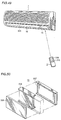
- FIG. 49 is a perspective view showing an appearance of an indoor unit of the conventional air conditioner. Recently, operation of the air conditioner is typically controlled by using a remote controller 3 for transmitting an instruction or a request to an indoor unit 1, as shown in Fig. 49.
- liquid crystal display 15 On indoor unit 1, a liquid crystal display 15 is arranged by the side of an air outlet 16 having an air directing plate 303 for changing the direction of air upward/downward. Liquid crystal display 15 displays various information including operation mode and temperature.
- Fig. 50 is an exploded perspective view of liquid crystal display 15. As can be seen from the exploded perspective view of Fig. 50, liquid crystal display 15 includes a combination of a liquid crystal panel 306 displaying characters, signs and the like, a backlight 307 consisting of a plurality of LEDs illuminating liquid crystal panel 306 from behind to make clear the liquid crystal display, and a unit cover 308 covering backlight 307 to make uniform the illuminating light incident on the liquid crystal panel 306.
- the remote controller 3 here includes a remote controller display unit 309 displaying pre-set contents of instruction, and various operation buttons 310 to be operated to transmit a necessary instruction for controlling operation of the air conditioner.
- An instruction necessary for controlling the operation of the air conditioner is transmitted as the operation buttons 310 are operated, from remote controller 2 to indoor unit 1.
- a ventilating operation, a humidifying operation or a dehumidifying operation of the air conditioner is desired.
- a humidifying operation or a dehumidifying operation of the air conditioner is desired.
- the user noticing such a state instructs an appropriate operation mode through the remote controller, generally such an operation is not executed.
- Some air conditioners have an indication of a recommended operation mode as well as the environment and condition in the room on the display unit so as to notify the user about the recommended operation mode. Such an indication, however, has been neglected or caused unnecessary concern, as it was difficult for the user to comprehend what kind of operation is to be done.
- Fig. 51 is a block diagram representing functions of the conventional air conditioner.
- the air conditioner includes, on a remote controller, a power consumption display means utilizing a liquid crystal for displaying consumed power, cooling/heating display means, room temperature display means, inverter frequency display means and a timer display means.
- Japanese Patent Laying-Open No. 11-101493 describes display of power consumption of air conditioning operation by kw unit, or by an amount equivalence of electricity charge.
- the prior art technique described above simply displays the power consumption of air conditioning operation by the unit of kw or by the amount equivalence of electricity charge.
- the unit electricity charge changes reflecting the change in economic conditions (such as exchange rate or crude oil price)
- the displayed amount may be erroneous.
- the display of the amount of electricity charge which is the equivalent of power consumption of the air conditioner operation will be erroneous, and the useful function would be meaningless.
- the present invention was made in order to solve the above described problems, and an object of the present invention is to provide an air conditioner solving the problem of ventilation and dehumidifying of the air conditioner.
- Another object of the present invention is to provide an air conditioner and a method of drying operation thereof enabling effective drying of laundry, by positively removing moisture in the room.
- a further object of the present invention is to provide an air conditioner capable of guiding a user to select an optimal operation mode in accordance with the environment and the condition of the apparatus itself changing with time and to ensure execution of the operation procedure. It is also an object to provide an air conditioner capable of providing an advice about a suitable operation mode enabling human friendly air conditioning.
- a still further object of the present invention is to provide an air conditioner capable of displaying power consumption of the operation of the air conditioner by an exact amount of electricity charge.
- an air conditioner in accordance with an aspect of the present invention including a refrigerant circuit formed by coupling at least a compressor, an indoor heat exchanger, a decompressor and an outdoor heat exchanger, and a humidifying/dehumidifying apparatus provided independent from the refrigerant circuit, for removing moisture in the room, characterized in that moisture detecting means for detecting moisture in the room and control means for switching an operation mode based on the moisture detected by the moisture detecting means are provided, and that the humidifying/dehumidifying apparatus leads the sucked air of the room to a path communicated to the room and to a path communicated to the outside of the room in a first operation mode, and leads the sucked air of the room to the outside of the room in the second operation mode.
- an air conditioner is provided that is capable of conditioning air in accordance with the environment.
- the present invention provides an air conditioner including a refrigerant circuit formed by coupling a compressor, a four way switching valve, an indoor heat exchanger, a decompressor and an outdoor heat exchanger, and a humidifying/dehumidifying apparatus provided independent from the refrigerant circuit, for removing moisture in the room, capable driving in an operation mode in that the refrigerant circuit and the humidifying/dehumidifying apparatus are driven simultaneously.
- moisture in the room is positively removed, and therefore an air conditioner capable of more effectively drying laundry can be provided.
- the present invention provides an air conditioner including a refrigerant circuit formed by coupling a compressor, an indoor heat exchanger and an outdoor heat exchanger, characterized in that a temperature sensor detecting a temperature of the air in the room, a moisture sensor detecting moisture of the air in the room, a display unit for displaying information and operation mode determining means for determining an optimal operation mode based on output from the aforementioned various sensors are provided, wherein the display unit displays an advice based on the result of determination made by the operation mode determining means.
- an air conditioner capable of guiding the user to select an optimal operation mold reflecting the environment and the conditions of the apparatus itself changing with time and to execute the operation procedures can be provided. Further, an air conditioner capable of providing an advice about the optimal operation mode for human friendly air conditioning can be provided.
- the present invention provides an air conditioner including a refrigerant circuit formed by coupling at least a compressor, an indoor heat exchanger, a decompressor and an outdoor heat exchanger, characterized in that it includes a load detecting unit detecting a load on the air conditioner, electricity charge calculating means for calculating electricity charge based on a unit charge and the detected load, a display unit displaying the calculated electricity charge, and unit charge changing means for changing the unit charge.
- an air conditioner capable of displaying the power consumption of the operation of the air conditioner by an equivalent exact amount of electricity charge can be provided.
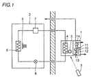
- Fig. 1 is a schematic diagram of the air conditioner in accordance with Embodiment 1A of the present invention.
- the air conditioner in accordance with Embodiment 1A includes an indoor unit 1, an outdoor unit 2 and a remote controller 3.
- Indoor unit 1 includes an indoor heat exchanger 4 and an indoor fan 5, while outdoor unit 2 includes an outdoor heat exchanger 6, a compressor 7, a decompressor 8 (expansion valve) and an outdoor fan 9.
- Indoor unit 1 contains an apparatus including a moisture absorbing rotor 11 absorbing or desorbing moisture in the room, a dehumidifying fan 11 sucking the air in the room, a recovery heater 12 recovering, by deabsorption, the moisture absorbing rotor, a recovery fan 13 feeding air for recovery to the moisture absorbing rotor, and a dumper 14 switching flow path.
- Fig. 2 is a perspective view of the indoor unit body of the air conditioner shown in Fig. 1.
- indoor unit 1 includes a body display unit 15 notifying the state of operation, an air outlet 16 blowing out heated/cooled air to the room, and an air inlet 17 sucking the air of the room.
- Fig. 3 is a schematic diagram of the body display unit of Fig. 2.
- body display unit 15 at the center of indoor unit 1.
- body display unit 15 includes a moisture lamp 18 which is turned on in accordance with the moisture in the room, a purity lamp 19 of which color changes in accordance with the degree of contamination of the room, a display unit 20 displaying indoor environment and the state of operation when "notification button" of remote controller 3 is pressed, and a light receiving portion 21 receiving a signal from the remote controller.
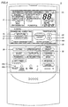
- Fig. 4 is a plan view of the remote controller shown in Fig. 1.
- Remote controller 3 shown in Fig. 4 includes a remote controller display unit 22 displaying the state of operation, a transmission display 23 which is turned on when a signal is transmitted to indoor unit 1, a "operation on/off" switch 24 for turning on/off the operation of the air conditioner, a temperature switch 25 for setting the indoor temperature, a dehumidifying switch 26 for turning on/off the dehumidifying operation, a ventilation switch 27 for turning on/off the ventilation operation, and an outing switch 28 for switching to an operation mode in which ventilation and/or dehumidifying operation is automatically started when the user goes out.
- a heat exchange medium at a high temperature condensed by compressor 7, is fed to outdoor heat exchanger 6 of outdoor unit 2.
- outdoor air deprives the heat exchange medium of heat as it passes through outdoor heat exchanger 6 by the operation of outdoor fan 9, and the heat exchange medium is cooled.
- the heat exchange medium passes through decompressor 8, evaporated at indoor heat exchanger 4 of indoor unit 1, and deprives the air in the room of heat as the air in the room is passed by the indoor fan 5 through the indoor heat exchanger 6. In this manner, the air in the room is cooled.
- Heating of the room is performed by reverse-circulating the heat exchange medium in the direction reverse to the cooling operation. More specifically, condensed heat exchange medium is fed to the indoor heat exchanger 4 of indoor unit 1, so as to warm up the air in the room passing through indoor heat exchanger 4. The heat exchange medium is further passed through the decompressor, evaporated at outdoor heat exchanger 6 of outdoor unit 2, and after the outdoor air is passed through outdoor heat exchanger 6 by indoor fan 9 and heat-exchange takes place, deprives the outdoor air of heat, and returns to compressor 7.
- the indoor air is sucked by a recovery fan 13, heated by recovery heater 12 and the air thus attained to a high temperature is fed to moisture absorbing rotor.
- the moisture in the moisture absorbing rotor 10 is deabsorbed, and the air containing much moisture is discharged to the outside of the room, so as to dehumidify the indoor environment.
- Operation mode of the air conditioner is switched every time the operation selecting switch 29 on the control panel of remote controller 3 is pressed, in the order of "automatic” - “heating” - “cooling” - “dry” - “automatic”, and the operation mode is displayed on display unit 22 of remote controller 3, and the user selects the operation mode accordingly.
- the set temperature is displayed on the body display unit 15 on indoor unit 1 as well as on the display unit 22 on the control panel of remote controller 3.
- the amount of temperature to be increased is displayed on display unit 22 on the control panel of remote controller 3, while the set temperature is displayed on body display unit 15 of indoor unit 1.
- the display of the set temperature on the body display unit 15 of indoor unit 1 returns to the display of the room temperature after approximately 4 seconds.
- the operation mode is switched to "dehumidifying" - "humidifying” - "stop” - “dehumidifying” every time the "moisture” switch 26 on the control panel of remote controller 3 is pressed, and when “dehumidifying” operation is selected, the 5-mode dehumidifying operation takes place.
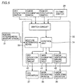
- Fig. 5 is a control block diagram representing functions of the air conditioner in accordance with Embodiment 1A
- Fig. 6 is a flow chart of the process performed by the air conditioner in accordance with Embodiment 1A.
- a moisture sensor 31 detecting moisture in the room is provided.
- the value of the moisture detected by moisture sensor 31 is input to moisture determining means 33 of a microcomputer 32 (step S2).
- the detected temperature is compared (step S3). If it is higher than a preset moisture (for example, moisture 70%), "5-mode dehumidifying” operation is performed (step S4), and if the detected temperature is lower than the preset moisture (for example, moisture 70%), “ventilation” operation is performed (step S5).
- the "5-mode dehumidifying” operation if the detected moisture is higher than the preset moisture (for example, moisture 70%) may be "dry" operation.
- Fig. 7 is a control block diagram representing functions of the air conditioner in accordance with Embodiment 1B of the present invention.
- Fig. 8 is a flow chart of the process performed by the air conditioner in accordance with Embodiment 1B of the present invention.
- Fig. 9 is a plan view of the remote controller in accordance with Embodiment 1B of the present invention. Embodiment 1B will be described with reference to Figs. 7, 8 and 9.
- remote controller 3 includes an outing switch 1 ⁇ 28 and an outing switch 2 ⁇ 38.
- a moisture sensor 31 for detecting indoor moisture is provided at an indoor air inlet 17 of indoor unit 11.
- the moisture is detected by moisture sensor 31 (step S13).
- the detected value of the moisture is input to moisture determining means 33 of microcomputer 32, which value is compared at a control unit 34 (step S14). If the value is lower than a preset moisture (for example, moisture 70%), "ventilation” operation is performed (step S19), and when the value is higher than the preset moisture (for example, moisture 70%), "5-mode dehumidifying” operation is performed. More specifically, when the value is higher than the preset moisture (for example, moisture 70%), whether the preset outing switch is switch 1 ⁇ (step S11) or switch 2 ⁇ (step S12) is detected (step S15), and determined (step S16).
- step S16 If the switch 1 ⁇ has been selected (YES in step S16), "5-mode dehumidifying” operation is performed (step S17), and if the switch 2 ⁇ has been selected (NO in step S16), "dry operation” is performed (step S18). Therefore, if a user dislikes "5-mode dehumidifying” operation in which the moisture absorbing rotor is recovered by the recovery heater while the user is out, the user may go back home to the room free of dumb hot atmosphere, though the electricity charge is relatively high.
- Fig. 10 is a control block diagram representing the functions of the air conditioner in accordance with Embodiment 1C of the present invention.
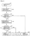
- Fig. 11 is a flow chart representing the flow of the process performed by the air conditioner in accordance with Embodiment 1C.
- the air conditioner in accordance with Embodiment 1C has a moisture sensor 31 detecting indoor moisture and a temperature sensor 43 detecting room temperature, provided at an indoor air inlet 17 of the indoor unit 1.
- the values of the detected moisture (step S22) and the temperature (step S24) are input to a moisture and temperature determining means 44 of microcomputer 31, and the values are compared at control unit 34 (steps S23, S25). If the moisture is higher than the preset moisture (for example, temperature 70%) (YES in step S23) and the temperature is higher than the preset temperature (for example, 10°C) (NO in step S25), "dry” operation 37 is performed (step S27). If the moisture is lower than the preset moisture (for example, moisture 70%) (NO in step S23) and the temperature is higher than the preset temperature (for example 10°C), "ventilation” operation 36 is performed (step S28).
- step S23 If the moisture is higher than the preset moisture (for example, moisture 70%) (YES in step S23) and the temperature is lower than the preset temperature (for example 10°C) (YES in step S25), "5-mode dehumidifying" operation 35 is performed (step S26).
- the preset moisture for example, moisture 70%
- the preset temperature for example 10°C
- step S26 dumb hot atmosphere of the room can be avoided, and when the temperature lowers, not the dehumidifying operation by the compressor but 5-mode dehumidifying operation utilizing zeolite is performed. Therefore, degradation of performance caused by frosting of the compressor can be avoided, dehumidifying ability is improved and the room will be more comfortable.
- the present invention provides an air conditioner including an outdoor unit containing at least a compressor, an outdoor heat exchanger, a four way switching valve and an outdoor fan, and an indoor unit 1 having at least an indoor heat exchanger and an indoor fan and containing an apparatus including a moisture absorbing rotor absorbing and desorbing moisture in the air of the room, a recovery heater recovering the moisture absorbing rotor and a recovery fan feeding air to the recovery heater, a switch is provided for selecting an operation mode of means automatically selecting dehumidifying operation or ventilating operation based on the moisture detected by a moisture sensor provided at an inlet of the indoor unit, and when the moisture detected by the moisture sensor provided at the inlet of the indoor unit is higher than a preset moisture, dehumidifying operation is performed, and if the moisture is lower than the preset moisture, ventilating operation is performed.
- an air conditioner including an outdoor unit containing at least a compressor, an outdoor heat exchanger, a four way switching valve and an outdoor fan, and an indoor unit 1 having at least an indoor heat exchanger and an
- means for selecting either a dry operation using a compressor or a 5-mode dehumidifying operation utilizing a moisture absorbing rotor in accordance with moisture and temperature detected by a moisture sensor and a temperature sensor provided at the inlet of the indoor unit is provided.
- dry operation using the compressor is performed.
- 5-mode dehumidifying operation utilizing the moisture absorbing rotor is performed.
- hot and dumb atmosphere of the room can be avoided.
- the temperature lowers, not the dry operation by the compressor but 5-mode dehumidifying operation using zeolite is performed. Therefore, degradation of performance resulting from frosting of the compressor can be avoided, dehumidifying capability is improved and the room will be more comfortable.
- Fig. 12 is a schematic diagram of the air conditioner in accordance with Embodiment 2 of the present invention.
- the air conditioner includes a refrigerating cycle apparatus 101, a humidifying/dehumidifying apparatus 102, and a control unit 103 controlling operations of these apparatuses.
- Refrigerating cycle apparatus 101 constitutes a closed refrigerant circuit, formed by coupling a compressor 104, a four way switching valve 105, an outdoor heat exchanger 106, a decompressor 107 and an indoor heat exchanger 108, and in addition includes an outdoor fan 109 and an indoor fan 110 promoting heat exchange by outdoor heat exchanger 106 and indoor heat exchanger 108.
- arrows represent the flow of the refrigerant.
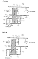
- Fig. 13 is a first illustration schematically showing a cross section of the humidifying/dehumidifying apparatus of the air conditioner in accordance with the present embodiment.
- Humidifying/dehumidifying apparatus 102 includes, as shown in Fig. 13, a moisture absorbing rotor 111 formed of a cylindrical ceramics or the like and having a moisture absorbing material provided on its surface, first and second exhaust paths 112 and 113 branched downstream of the moisture absorbing rotor 111 and communicated to the outside of the room, a moisture absorbing fan 114 feeding sucked air through the moisture absorbing rotor 111 and exhausting the air through the first exhaust path 112 to the outside of the room, a heater 115 provided in the second exhaust path 113 and heating the air which passes through the moisture absorbing rotor 111, and a recovery fan 116 to desorb moisture from the moisture absorbing rotor 111 by feeding the air heated by the heater 115 through the moisture absorbing rotor 111 and evacuating moisted water through the second exhaust path 113 to the outside of the room.
- indoor temperature sensor 117 detects room temperature
- moisture sensor 118 detects moisture in the room
- outdoor temperature sensor 118 detects outdoor temperature
- these sensors are connected to the input side of control unit 103.
- the receiving unit 120 receives various wireless signals generated by the operation of remote controller 121 and inputs the received signals to control unit 103.
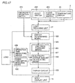
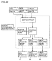
- compressor 104 On the output side of control unit 103, compressor 104 is connected through a variable frequency control circuit (hereinafter referred to as "inverter circuit") 122, and the four way switching valve 105, a fan motor 110a of outdoor fan 109, a fan motor 10a of indoor fan 110, a motor 111a for rotating moisture absorbing rotor 111, a fan motor 114a of moisture absorbing fan 114, heater 115 and a fan motor 116a of recovery fan 116 are connected through a relay circuit 123, respectively.
- An indoor fan control circuit 124 controls the number of rotation of indoor fan 110.
- control unit 103 closes relay r2 to switch the four way switching valve 105 to the position of the dotted line, and closes relays r1 and r3 to drive outdoor fan 109 and indoor fan 110.
- inverter circuit 122 functions and compressor 104 starts an operation, so that the refrigerant gas is fed to outdoor heat exchanger 106.
- the refrigerant gas is subjected to heat exchange with the outdoor air at the outdoor heat exchanger to be condensed and liquefied, and thereafter decompressed by decompressor 107 and evaporated at indoor heat exchanger 108.
- control unit 103 switches four way switching valve 105 to the position of the solid line, and by the repetition of cycles in the reverse direction to the cooling or dehumidifying operation, the room is heated.
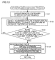
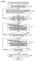
- Fig. 15 is a flow chart representing the flow of the operation switching process that takes place in the air conditioner in accordance with Embodiment 2A of the present invention.
- a dry operation mode is selected by an operation of a remote controller 121 (step S101).
- room temperature and outdoor temperature are detected by an indoor temperature sensor 117 and an outdoor temperature sensor 119, respectively (step S102).
- control unit 103 determines whether the detected room temperature is lower than a preset temperature, for example, lower than 21 °C, and the detected outdoor temperature is lower than the preset temperature, for example, lower than 18 °C, are determined (step S103). If it is true, the flow proceeds to step S104, and if not, the flow proceeds to step S102.
- control unit 103 switches a refrigerating cycle apparatus 101 to operate in a heating operation mode, and at the same time, switches a humidifying/dehumidifying apparatus 102 to operate in a dehumidifying mode.
- Switching of the humidifying/dehumidifying apparatus 102 to the dehumidifying mode is done when control unit 103 closes relays r4 to r7 of relay circuit 123, and motor 111a for rotating moisture absorbing rotor, moisture absorbing fan motor 114a, heater 115 and recovery fan motor 116a of humidifying/dehumidifying apparatus 102 are electrically conducted.
- Fig. 13 is a schematic cross section representing humidifying/dehumidifying apparatus 102 in the dehumidifying mode.
- the air A1 in the room is taken in by moisture absorbing fan 114 and passed through moisture absorbing rotor 111.
- the moisture-absorbing rotor 111 absorbs the moisture in the air.
- the dry air A2 after passing moisture absorbing rotor 111 is exhausted to the outside of the room through a first exhaust path 112. That portion of moisture absorbing rotor 111 which absorbed the moisture moves toward a second exhaust path as the moisture absorbing rotor 111 rotates.
- part of the indoor air A3 is taken by a recovery fan 116, passed through moisture absorbing rotor 111 and flows into the second exhaust path 113 as dry air A4.
- a heater 115 to a high temperature heats the air A4.
- the air passes again the moisture absorbing rotor 111 from behind, it desorbs the moisture that has been absorbed by the moisture absorbing rotor 111, and emitted to the outside of the room as highly moist air A5 through the second exhaust path 113.
- the moisture absorbing rotor thus recovered with the moisture removed is rotated and again exhibits moisture-absorbing capability.
- Fig. 16 is a flow chart representing the flow of the operation switching process that takes place in the air conditioner in accordance with Embodiment 2B of the present invention.
- a dehumidifying operation mode is selected by an operation of remote controller 121 (step S111).
- indoor temperature and outdoor temperature are detected by indoor temperature sensor 117 and outdoor temperature sensor 119, respectively (step S112).
- control unit 103 determines whether the detected room temperature is higher than a preset temperature, for example, higher than 21°C and the detected outdoor temperature is higher than the preset temperature, for example, higher than 18°C, are determined (step S113). If it is true, the flow proceeds to step S114, and if not, the flow proceeds to step S112.
- control unit 103 switches the refrigerating cycle apparatus 101 to operate in a dry operation mode, and at the same time, switches humidifying/dehumidifying apparatus 102 to operate in the dehumidifying mode.
- Switching of humidifying/dehumidifying apparatus 102 to the dehumidifying mode is done when control unit 103 closes relays r4 to r7 of relay circuit 123, and motor 111a for rotating moisture absorbing rotor, moisture absorbing fan motor 114a, heater 115 and recovery fan motor 116 are electrically conducted.
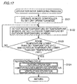
- Fig. 17 is a flow chart representing the flow of the operation switching process that takes place in the air conditioner in accordance with Embodiment 2C of the present invention.
- the dry operation mode is selected by an operation of remote controller 121 (step S121).
- room temperature and outdoor temperature are detected by indoor temperature sensor 117 and outdoor temperature sensor 119, respectively (step S122).
- control unit 103 determines whether the detected room temperature is lower than a preset temperature, for example, lower than 21°C, and the detected outdoor temperature is lower than a preset temperature, for example, lower than 18°C, are determined (step S123). If it is true, the flow proceeds to step S124, and if not, the flow proceeds to step S122.
- control unit 103 switches the refrigerating cycle apparatus 101 to operate in the heating operation mode, and at the same time, switches the humidifying/dehumidifying apparatus 102 to operate in a ventilation mode. Switching of humidifying/dehumidifying apparatus to the ventilation mode is done when control unit 103 closes relay r5 of relay circuit 123 and moisture absorbing fan motor 114a of humidifying/dehumidifying apparatus 102 is electrically conducted.
- Fig. 14 is a schematic cross section showing humidifying/dehumidifying apparatus 102 operating in the ventilation mode.
- indoor air A1 is sucked by moisture absorbing fan 114, passed to moisture absorbing rotor 111, and evacuated to the outside of the room through the second exhaust path 112 (A2).
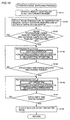
- Fig. 18 is a flow chart representing the flow of the operation switching process that takes place in the air conditioner in accordance with Embodiment 2D of the present invention.
- the dry operation mode is selected by an operation of remote controller 121 (step S131).
- room temperature and outdoor temperature are detected by indoor temperature sensor 117 and outdoor temperature sensor 119, respectively (step S132).
- control unit 103 determines whether the detected room temperature is higher than a preset temperature, for example, higher than 21°C, and the detected outdoor temperature is higher than a preset temperature, for example, higher than 18°C, are determined (step S133). If it is true, the flow proceeds to step S134, and if not, the flow proceeds to step S132.
- control unit 103 switches the refrigerating cycle apparatus 101 to operate in the dry operation mode, and at the same time, switches the humidifying/dehumidifying apparatus 102 to operate in the ventilating mode. Switching of humidifying/dehumidifying apparatus to the ventilating mode is done when control circuit 103 closes relay r5 of relay circuit 123 and moisture absorption fan motor 114a of humidifying/dehumidifying apparatus 102 is electrically conducted.
- indoor air A1 is taken in by moisture absorbing fan 114, passed through moisture absorbing rotor 111 and exhausted to the outside of the room through the second exhaust path 112 (A2).
- Fig. 19 is a flow chart representing the flow of the operation switching process that takes place in the air conditioner in accordance with Embodiment 2E of the present invention.
- the dry operation mode is selected by an operation of remote controller 121 (step S 141).
- room temperature and outdoor temperature are detected by indoor temperature sensor 117 and outdoor temperature sensor 119, respectively (step S132).
- control unit 103 determines whether the detected room temperature is lower than a preset temperature, for example, lower than 21°C, and the detected outdoor temperature is lower than a preset temperature, for example, lower than 18°C, are determined (step S143). If it is true, the flow proceeds to step S144, and if not, the flow proceeds to step S142.
- control unit 103 switches the refrigerating cycle apparatus 101 to operate in the heating operation mode and, at the same time, switches humidifying/dehumidifying apparatus 102 to operate in the dehumidifying mode.
- the dry operation time is set to a prescribed time period (for example, 4 hours).
- Switching of the humidifying/dehumidifying apparatus 102 to the dehumidifying mode is done when control unit 103 closes relays r4 to r7 of relay circuit 123, and motor 111a for rotating moisture absorbing rotor, moisture absorbing fan motor 114a, heater 115 and receiver fan motor 116 of humidifying/dehumidifying apparatus 102 are electrically conducted.
- step S145 whether the time passed from the start of drying operation has attained a time period that is the prescribed operation time (in this example, 4 hours) minus a specific time period (for example, 30 minutes) is determined (step S145). If the time has passed, the flow proceeds to step S146, and if not, the flow proceeds to step S144.
- a time period that is the prescribed operation time (in this example, 4 hours) minus a specific time period (for example, 30 minutes) is determined (step S145). If the time has passed, the flow proceeds to step S146, and if not, the flow proceeds to step S144.
- step S146 in response to an instruction from control unit 103, the refrigerating cycle apparatus 101 is switched to operate in the dry operation mode. At this time, the operation of humidifying/dehumidifying apparatus 102 in the dehumidifying mode is continued.
- step S147 whether the prescribed time period has passed from the start of drying operation mode is determined, and if the time has passed, the flow proceeds to step S148, and if not, proceeds to step S146.
- step S148 the operation of the air conditioner in the dry operation mode is stopped.
- Fig. 20 is a flow chart representing the flow of the operation switching process that takes place in the air conditioner in accordance with Embodiment 2F of the present invention.
- the dry operation mode is selected by an operation of remote controller 121 (step S151).
- the room temperature and the outdoor temperature are detected by indoor temperature sensor 117 and outdoor temperature sensor 119, respectively (step S152).
- control unit 103 determines whether the detected room temperature is lower than a preset temperature, for example, lower than 21°C, and the detected outdoor temperature is lower than a preset temperature, for example, lower than 18°C, are determined (step S153). If it is true, the flow proceeds to step S154, and if not, the flow proceeds to step S152.
- control unit 103 switches the refrigerating cycle apparatus 101 to operate in the heating operation mode and, at the same time, switches humidifying/dehumidifying apparatus 102 to operate in the dehumidifying mode.
- the dry operation time is set to a prescribed time period (for example, 4 hours).
- Switching of humidifying/dehumidifying apparatus 102 to the dehumidifying mode is done when control unit 103 closes relays r4 to r7 of relay circuit 123, and motor 111a for rotating moisture absorbing rotor, moisture absorbing fan motor 114a, heater 115 and recovery fan motor 116a of humidifying/dehumidifying apparatus 102 are electrically conducted.
- step S155 whether the time passed from the start of the dry operation mode has attained the time that is the prescribed time period (in this example, 4 hours) minus a specific time period (for example, 30 minutes) or not is determined (step S155). If the time has passed, the flow proceeds to step S156, and if not, the flow proceeds to step S154.
- the prescribed time period in this example, 4 hours
- a specific time period for example, 30 minutes
- step S156 based on an instruction from control unit 103, refrigerating cycle apparatus 101 is switched to operate in the dry operation mode and, at the same time, humidifying/dehumidifying apparatus 102 is switched to operate in the ventilating mode.
- step S157 whether the prescribed time period has passed from the start of dry operation mode or not is determined, and if the time has passed, the flow proceeds to step S158 and if not, proceeds to step S156.
- step S158 the operation of the air conditioner in the dry operation mode is stopped.
- Fig. 21 is a flow chart representing the flow of the operation switching process that takes place in the air conditioner in accordance with Embodiment 2G of the present invention.
- a dry operation mode is selected by an operation of remote controller 121 (step S161).
- room temperature and outdoor temperature are detected by indoor temperature sensor 117 and outdoor temperature sensor 119, respectively (step S162).
- control unit 103 determines whether the detected room temperature is higher than a preset temperature, for example, higher than 21°C, and the detected outdoor temperature is higher than a preset temperature, for example, higher than 18°C, are determined (step S163). If it is true, the flow proceeds to step S164, and if not, the flow proceeds to step S162.
- control unit 103 switches refrigerating cycle apparatus 101 to operate in the dry operation mode and, at the same time, switches humidifying/dehumidifying apparatus 102 to operate in the dehumidifying mode.
- the dry operation time is set to a prescribed time period (for example, 4 hours).
- Switching of humidifying/dehumidifying apparatus to the dehumidifying mode is done when control unit 103 closes relays r4 to r7 of relay circuit 123 and motor 111a for rotating moisture absorbing rotor, moisture absorbing fan motor 114a, heater 115 and recovery fan motor 116 of humidifying/dehumidifying apparatus 102 are electrically conducted.
- step S165 whether the time passed from the start of the dry operation mode has attained the time that is the prescribed operation time (in this example, 4 hours) minus a specific time period (for example, 30 minutes) or not is determined (step S165). If the time has passed, the flow proceeds to step S166, and if not, proceeds to step S164.
- the prescribed operation time in this example, 4 hours
- a specific time period for example, 30 minutes
- step S166 based on the instruction from control unit 103, refrigerating cycle apparatus 101 is continuously operated in the dry operation mode, and humidifying/dehumidifying apparatus 102 is switched to operate in the ventilating mode.
- step S167 whether the prescribed time has passed from the start of the dry operation mode or not is determined, and if the time has passed, the flow proceeds to step S168 and if not, proceeds to step S166.
- step S168 operation of the air conditioner in the dry operation mode is stopped.
- Fig. 22 is a flow chart representing the flow of the operation switching process that takes place in the air conditioner in accordance with Embodiment 2H of the present invention.
- a dry operation mode is selected by an operation of remote controller 121 (step S171).
- room temperature and outdoor temperature are detected by indoor temperature sensor 117 and outdoor temperature sensor 119, respectively (step S172).
- control unit 103 determines whether the detected room temperature is lower than a preset temperature, for example, lower than 21°C, and the detected outdoor temperature is lower than a preset temperature, for example, lower than 18°C, are determined (step S173). If it is true, the flow proceeds to step S174, and it not, the flow proceeds to step S172.
- control unit 103 switches refrigerating cycle apparatus 101 to operate in heating operation mode and, at the same time, switches humidifying/dehumidifying apparatus 102 to operate in the dehumidifying mode.
- dry operation time is set to a prescribed time period (for example, 4 hours).
- Switching of humidifying/dehumidifying apparatus 102 to the dehumidifying mode is done when control unit 103 closes relays r4 to r7 of relay circuit 123 and motor 111a for rotating moisture absorbing rotor, moisture absorbing fan motor 114a, heater 115 and recovery fan motor 116a of humidifying/dehumidifying apparatus 102 are electrically conducted.
- step S175 whether time passed from the start of the dry operation mode has attained the time that is the prescribed operation time (in this example, 4 hours) minus a specific time period (for example 30 minutes) is determined (step S175). If the time has passed, the flow proceeds to step S176, and if not, proceeds to step S174.
- the prescribed operation time in this example, 4 hours
- a specific time period for example 30 minutes
- step S176 based on an instruction from control unit 103, refrigerating cycle apparatus 101 is switched to operate in the dry operation mode. At this time, humidifying/dehumidifying apparatus 102 is continuously operated in the dehumidifying mode.
- step S177 whether the prescribed time period has passed from the start of the dry operation mode is determined, and if the time has passed, the flow proceeds to step S180, and if not, the flow proceeds to step S178.
- step S178 whether compressor 104 of the air conditioner is stopped or not is determined. If the compressor is stopped, the flow proceeds to step S179, and if not, the flow returns to step S176. Therefore, while the compressor 104 is stopped, the process step S179 is executed.
- step S179 an instruction is given from control unit 103 to indoor fan control circuit 124, and indoor fan 110 is operated with high flow rate. At this time, operation of refrigerating cycle apparatus 101 in the dry operation mode and operation of humidifying/dehumidifying apparatus 102 in the dehumidifying mode are continued.
- step S180 the operation of the air conditioner in the dry operation mode is stopped.
- Fig. 23 is a flow chart representing the flow of the operation switching process that takes place in the air conditioner in accordance with Embodiment 2I of the present invention.
- the dry operation mode is selected by an operation of remote controller 121 (step S181).
- room temperature and outdoor temperature are detected by indoor temperature sensor 117 and outdoor temperature sensor 119, respectively, and moisture in the room is detected by the moisture sensor 118 (step S182).
- control unit 103 determines whether the detected room temperature is lower than a preset temperature, for example, lower than 21°C, and the detected outdoor temperature is lower than a preset temperature, for example, lower than 18°C, are determined (step S183). If it is true, thus flow proceeds to step S184, and if not, the flow proceeds to step S182.
- step S184 whether the detected moisture is higher than a preset moisture, for example, higher than 80%, is determined. If it is higher, the flow proceeds to step S185, and if it is lower, the flow proceeds to step S186.
- a preset moisture for example, higher than 80%
- control unit 103 switches refrigerating cycle apparatus 101 to operate in the heating operation mode, and at the same time, switches humidifying/dehumidifying apparatus 102 to operate in the ventilating mode.
- control unit 103 switches refrigerating cycle apparatus 101 to operate in the heating operation mode and, at the same time, switches humidifying/dehumidifying apparatus 102 to operate in the dehumidifying mode.
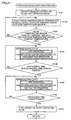
- Fig. 24 is a flow chart representing the flow of the operation switching process that takes place in the air conditioner in accordance with Embodiment 2J of the present invention.
- the drying operation mode is selected by an operation of remote controller 121 (step S191).
- the room temperature and outdoor temperature are detected by indoor temperature sensor 117 and outdoor temperature sensor 119, respectively and moisture in the room is detected by moisture sensor 118 (step S192).
- control unit 103 determines whether the detected room temperature is higher than a preset temperature, for example, higher than 21°C, and the detected outdoor temperature is higher than a preset temperature, for example, higher than 18°C, are determined (step S193). If it is true, the flow proceeds to step S194, and if not, the flow proceeds to step S192.
- a preset temperature for example, higher than 21°C
- a preset temperature for example, higher than 18°C
- step S194 whether detected moisture is higher than a preset moisture, for example, higher than 80% or not is determined. If it is higher, the flow proceeds to step S195, and if it is lower, the flow proceeds to step S196.
- a preset moisture for example, higher than 80% or not
- control unit 103 switches refrigerating cycle apparatus 101 to operate in the dry operation mode, and switches humidifying/dehumidifying apparatus 102 to operate in the ventilating mode.
- control unit 103 switches refrigerating cycle apparatus 101 to operate in the dry operation mode, and at the same time, switches humidifying/dehumidifying apparatus 102 to operate in the dehumidifying mode.
- the humidifying/dehumidifying apparatus is used additionally to dry the laundry, together with heating or dehumidifying operation by the refrigerating cycle apparatus. Therefore, as compared with the drying solely by the refrigerating cycle apparatus, the laundry can be dried in a shorter time with high efficiency. Even when the compressor is stopped, the laundry can be dried by the humidifying/dehumidifying apparatus, and therefore, the drying operation time can be used effectively.
- Fig. 2 shows a main portion of the indoor unit of the air conditioner in accordance with Embodiment 3A
- Fig. 3 schematically shows the liquid crystal display
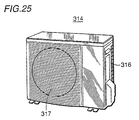
- Fig. 25 is a plan view representing a main portion of the outdoor unit.
- Fig. 26 is a plan view showing a main portion of the remote controller.
- Fig. 27 is a schematic cross section showing the internal structure of the indoor unit, and
- Fig. 28 is a cross section schematically showing the internal structure of the outdoor unit.
- the air conditioner in accordance with Embodiment 3A includes, as in the prior art, an indoor unit 1 and an outdoor unit 314.
- the operation of the air conditioner is controlled by a microcomputer (not shown) receiving an instruction transmitted from a remote controller 3.
- indoor unit 1 has an indoor cabinet 311 formed of resin, for example, having an air inlet 17 at a front side and an air outlet 16, in which an air directing plate 303 is attached, at a lower side.
- cooling and heating equipment such as the indoor heat exchanger 318 and an indoor fan 319 is arranged.
- the reference character A represents the indoor airflow
- the character B represents the wall surface.
- a moisture sensor 313 is attached near the air inlet 17, so as to detect the indoor moisture.
- a liquid crystal display 15 is provided, inclined slightly downward with an angle for better view, approximately at the center of the front face of indoor cabinet 311. More specifically, the liquid crystal display 15 is provided to give various information such as the operation mode and the temperature.
- Liquid crystal display 15 includes a combination of: a liquid crystal display panel 306 displaying characters, signs and the like; a back light 307 formed of a plurality of LEDs illuminating and clarifying the liquid crystal display; and a unit cover 308 covering the back light 307 and making uniform the light incident on and illuminating liquid crystal panel 306.
- liquid crystal display 15 be arranged approximately at the center of indoor cabinet 311 above air outlet 16. It is needless to say that the display may be arranged at any other place as long as it is on the front side of indoor unit 11. Further, the light emitting element of back light 307 is not limited to LEDs and EL light emitting a plurality of colors may be used.
- Outdoor unit 314 has an outdoor unit 315 formed of metal, for example, as shown in Figs. 25 and 28.
- An air inlet 316 sucking outdoor air is formed in three directions of outdoor cabinet 315, and an air outlet 317 exhausting the heat-exchanged air is formed approximately at the center of the remaining direction.
- a cooling and heating equipment (not shown) is provided, including an outdoor heat exchanger 320, a compressor, a decompressor, an outdoor fan 321, and a temperature sensor detecting the outdoor temperature.
- the reference character A represents a passage of the outdoor air.
- Fig 29 is a flow chart representing the advice displaying process that takes place in the air conditioner of Embodiment 3A.
- the indoor moisture is detected by a moisture sensor 313 arranged in indoor unit 1
- outdoor temperature is detected by outdoor temperature sensor 322 arranged in outdoor unit 314 (step S201).
- the indoor air moisture and the outdoor temperature are monitored by a microcomputer through moisture sensor 313 and outdoor temperature sensor 322. Whether, by abrupt change in the weather, the indoor air moisture and the outdoor temperature attains higher than a predetermined indoor moisture (for example, moisture of 80% or higher) and lower than a reference value of the outdoor temperature (for example, 18 °C or lower), respectively, are determined (step S202). If it is yes, the flow proceeds to step S203, and if not, it proceeds to step S201.
- a predetermined indoor moisture for example, moisture of 80% or higher
- a reference value of the outdoor temperature for example, 18 °C or lower
- step S203 the display on liquid crystal display 15 arranged at the indoor cabinet 311 of indoor unit 1 is switched from a normal display to an advice display.
- a normal display temperature in operation, for example, is given, while in the advice display, an advice recommending ventilation operation is given.
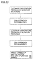
- Fig. 30 represents an example of the advice display given on the liquid crystal display 15 in Embodiment 3A.
- the advice display "outdoor temperature decreased, moisture increased” and “dry operation recommended” are displayed alternately and repeatedly for 5 seconds each, and finally, “press operation switch button and dry operation starts” is displayed for 10 seconds.
- the advice display includes a notice recommending switching of the operation mode as well as a button to be pressed for necessary operation to switch the operation mode.
- liquid crystal display 15 gives the advice display recommending execution of the dry operation, the user is easily reminded of the necessity of the dry operation.
- step S204 the user, noticing the advice display by liquid crystal display 15, instructs dry operation.
- the instruction by the user of the dry operation is given by pressing "operation switch button" 310a among the operation buttons 310 of remote controller 3 as shown in Fig. 26.
- an instruction requesting execution of dry operation by the compressor is given to the indoor unit 1.
- step S105 executes the dry operation. Accordingly, the moisture in the air is removed by the dry operation, and moisture in the room reduces to a comfortable range. Thus, convenience of the air conditioner is significantly improved.
- Fig. 31 is a schematic cross section representing the internal structure of the indoor unit in accordance with Embodiment 3B.
- the relation between the indoor unit, outdoor unit and the remote controller, and the structure of the liquid crystal display in accordance with Embodiment 3B are the same as in the prior art, and the structure of the main portion of the indoor unit is the same as that of Embodiment 3A. Therefore, components and portions corresponding to those of Figs. 2, 27, 49 and 50 are denoted by the same reference characters, and detailed description thereof will not be repeated here.
- the air conditioner in accordance with Embodiment 3B includes indoor unit 1, and in an indoor cabinet 311 of indoor unit 1, a moisture sensor 329 arranged near an air inlet 17 for detecting moisture of the indoor air, and a humidifying/dehumidifying apparatus 323 for removing moisture from the indoor air are contained.
- the humidifying/dehumidifying apparatus 323 here includes a moisture absorbing path formed by a moisture absorbing rotor 324 having a moisture absorbing material such as zeolite absorbing water applied thereon and a moisture absorbing fan 325 feeding the indoor air taken in by moisture absorbing rotor 324 to the room through air outlet 16, and a recovery path including a recovery heater 326 heating the air and a recovery fan 327 feeding the heated air to moisture absorbing rotor 324 for desorbing moisture of the moisture absorbing rotor.
- the humidifying/dehumidifying apparatus is similar to the apparatus described in Japanese Patent Laying-Open Nos. 8-270980 and 10-477706.
- Fig. 32 is a flow chart representing the advice displaying process that takes place in the air conditioner of Embodiment 3B.
- the indoor moisture is detected by moisture sensor 313 arranged in indoor unit 1 (step S211).
- the indoor air moisture is monitored by a microcomputer through moisture sensor 313.
- step S121 Whether the indoor air moisture during the operation of the air conditioner is lower than a preset moisture (for example, lower than 30%) or not is determined (step S121). If it is true, the flow proceeds to step S213, and if not, the flow proceeds to step S211.
- a preset moisture for example, lower than 30%
- step S213 the display on liquid crystal display 15 arranged on indoor cabinet 311 of indoor unit 1 is switched from a normal display to an advice display.
- a normal display temperature in operation, for example, is given, while in the advice display, an advice recommending execution of a humidifying operation is given.
- Fig. 33 represents an example of the advice display given on the liquid crystal display 15 in Embodiment 3B.
- the advice display includes a notice recommending switching of the operation mode as well as a button to be pressed for necessary operation to switch the operation mode.
- liquid crystal display 15 gives the advice display recommending execution of the humidifying operation, the user is easily reminded of the necessity of the humidifying operation.
- step S214 the user, noticing the advice display by liquid crystal display 15, instructs humidifying operation of the humidifying/dehumidifying apparatus (step S214).
- the instruction by the user of the humidifying operation of the humidifying/dehumidifying apparatus is given by pressing "moisture button" 310b among the operation button 310 of remote controller 3, as shown in Fig. 25.
- an instruction requesting execution of humidifying operation by the humidifying/dehumidifying apparatus is given to the indoor unit 1.
- the humidifying operation by the humidifying/dehumidifying apparatus 323 is executed simultaneously when the air conditioner is in operation, and the humidifying operation is executed by itself by the humidifying/dehumidifying apparatus 323 when the air conditioner is not in operation (step S215). Accordingly, the moisture of the indoor air taken in by dehumidifying fan 325 is absorbed by moisture absorbing rotor 324, and the dried air is discharged to the outside of the room. The air heated by recovery heater 326 is fed to moisture absorbing rotor 324 by recovery fan 327, desorbs moisture of the absorbing rotor 324, and the resulting moist air is fed to the room. Thus, the indoor air is humidified.
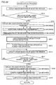
- Fig. 34 shows the relation between change with time and the threshold value of indoor moisture.
- a preset moisture B moisture 30%
- humidifying operation by humidifying/dehumidifying apparatus 323 is executed, and indoor moisture increases.
- moisture of the indoor air attains to an appropriate level, and the moisture of the indoor air becomes higher than the reference moisture B.
- step S216 the moisture of the indoor air is detected by moisture sensor 313 arranged in indoor unit 1. Whether the moisture of the indoor air during the operation of the air conditioner has attained higher than the preset moisture B or not is determined (step S217). If it is true, the flow proceeds to step S218, and if not, the flow proceeds to step S216.
- step S218 the display on liquid crystal display 15 arranged on indoor cabinet 311 of indoor unit 1 is switched from the normal display to an advice display.
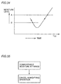
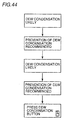
- Fig. 35 is a second illustration showing an example of the advice display given on liquid crystal display 15 of Embodiment 3B.
- the advice display "comfortable moisture attained” and “cancel humidifying operation” are displayed alternately and repeatedly for 5 seconds each. In this manner, as the advice display, notification recommending change in the operation mode is given.
- liquid crystal display 15 gives the advice display recommending cancellation of the humidifying operation, the user is easily reminded of the necessity of canceling the humidifying operation.
- step S219 the user, noticing the advice display by liquid crystal display 15, stops the humidifying operation of the humidifying/dehumidifying apparatus.
- the instruction by the user of stopping the humidifying operation by the humidifying/dehumidifying apparatus is given by an operation of remote controller 3, as shown in Fig. 26.
- the humidifying operation by the humidifying/dehumidifying apparatus is stopped.
- the normal display is given on liquid crystal display 15.
- Fig. 36 is a schematic cross section showing the internal structure of the indoor unit in accordance with Embodiment 3C.
- the air conditioner in accordance with Embodiment 3C includes an indoor unit 1, and operation of the air conditioner is controlled by a microcomputer (not shown) receiving an instruction transmitted from remote controller 2.
- indoor unit 1 includes an indoor cabinet 311 formed of resin, for example, and in the indoor cabinet 311 having an air inlet 17 formed at a front side position and an air outlet 16 containing an air directing plate 303 changing the direction of the wind in upward/downward formed at a lower position, there is cooling/heating equipment (not shown) such as an indoor heat exchanger 318 and an indoor fan 319.
- the reference character A represents the distribution path of the indoor air
- the reference character B represents a wall surface, respectively.
- a gas sensor 329 is arranged near air inlet 17 of indoor cabinet 311 provided in indoor unit 1, for detecting contamination of the indoor air.
- a ventilating apparatus exhausting dirty indoor air to the outside of the room is provided.
- a humidifying/dehumidifying apparatus 323 such as disclosed in Japanese Patent Laying-Open Nos. 8-270980 and 10-477706 proposed by the applicant of the present invention may be used as the ventilating apparatus.
- the humidifying/dehumidifying apparatus 323 includes a moisture absorbing path formed by a moisture absorbing rotor 324 having a moisture absorbing material such as zeolite absorbing water applied thereon, and a dehumidifying fan 325 leading the indoor air taken in by the moisture absorbing rotor 324 to the room through air outlet 16.
- Humidifying/dehumidifying apparatus 323 additionally includes a recovery path including a recovery heater 326 heating the air, and a recovery fan 327 feeding the heated air to the moisture absorbing rotor 324 for the desorbing the moisture of the moisture absorbing rotor.
- the system utilizes the moisture absorbing path to take in the dirty air of the room by dehumidifying fan 325 and exhausting the dirty air to the outside of the room through moisture absorbing rotor 324, and the recovery path is not used for this operation.
- the air cleaner may be a combination of a cleaning filter and a circulating fan that takes in the indoor air through the cleaning filter and blows out the air to the room through the air outlet, or it may be formed by using an electric dust collector (not shown).
- liquid crystal display 15 that is, liquid crystal display 15 for displaying various information such as the operation mode and the temperature is arranged.
- liquid crystal display 15 has such a structure that includes a liquid crystal panel 306 displaying characters, signs and the like, a backlight 307 formed of a plurality of LEDs illuminating the liquid crystal panel 306 from behind to make clear the liquid crystal display, and a unit cover 308 covering backlight 307 and making uniform the illuminating light incident on liquid crystal panel 306. It is not necessary that liquid crystal display 15 is arranged on the side of air outlet 16, and naturally, it may be arranged at any other position on the front side of indoor unit 1.
- the light emitting element of backlight 307 is not limited to LEDs, and EL light emitting a plurality of different colors may be used.
- Fig. 37 is a flow chart representing the advice displaying process that takes place in the air conditioner in Embodiment 3C.
- the advice displaying process first, degree of contamination in the room is detected by gas sensor 329 arranged on indoor unit 1 (step S221). The degree of contamination of the indoor air is monitored by a microcomputer through gas sensor 329.
- step S222 Whether the degree of contamination of the indoor air during the operation of air conditioner has exceeded a preset reference value (reference value A of Fig. 38) or not is determined (step S222). If it is true, the flow proceeds to step S223, and if not, the flow proceeds to step S221.
- step 223 the display on liquid crystal display 15 arranged at the indoor cabinet 311 of indoor unit 1 is switched from a normal display to an advice display.
- a normal display temperature in operation, for example, is given, while in the advice display, an advice recommending execution of ventilation operation is given.
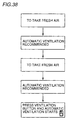
- Fig. 38 is a first illustration representing an example of the advice display given on the liquid crystal display 15 in Embodiment 3C.
- the advice display "to take in fresh air” and “automatic ventilation recommended” are displayed alternately and repeatedly for 5 seconds each, and finally, “press ventilation button and ventilation starts” is displayed for 10 seconds.
- the advice display includes notice recommending switching of the operation mode as well as a button to be pressed for necessary operation to switch the operation mode.
- liquid crystal display 15 gives the advice display recommending execution of air cleaning operation, the user is easily reminded of the necessity of the air cleaning operation.
- step S224 the user, noticing the advice display by liquid crystal display 15, instructs additional automatic ventilation operation.
- the instruction by the user of the additional automatic ventilating operation is given by pressing "ventilation button" 310c among the operation buttons 310 of remote controller 3, as shown in Fig. 26.
- an instruction requesting execution of automatic ventilating operation is given to indoor unit 1.
- the ventilating operation by humidifying/dehumidifying apparatus 323 is additionally performed in the air conditioner in operation, and the ventilating operation by humidifying/dehumidifying apparatus 323 by itself is executed when the air conditioner is not in operation (step S225).
- the ventilating operation by humidifying/dehumidifying apparatus 323 by itself is executed when the air conditioner is not in operation (step S225).
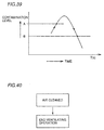
- Fig. 39 represents the change in the degree of contamination of the indoor air with time and the threshold value.
- Fig. 39 when the degree of contamination of the indoor air during the operation of the air conditioner exceeds a preset degree of contamination A, automatic ventilating operation by humidifying/dehumidifying operation 323 is executed, decreasing the degree of contamination.
- the contamination of the indoor air is eliminated, and degree of contamination of the indoor air becomes lower than the preset degree of contamination B.
- step S226 the degree of contamination of the indoor air is detected by gas sensor 329 arranged on indoor unit 1. Whether the degree of contamination of the indoor air during the operation of the air conditioner is smaller than the preset degree of contamination B or not is determined (step S227). If it is true, the flow proceeds to step S228, and if not, the flow proceeds to S226.
- step S2208 the display on liquid crystal display 15 arranged on indoor cabinet 311 of indoor unit 1 is switched from a normal display to an advice display.
- an advice notifying that humidifying operation will be terminated is given.
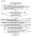
- Fig. 40 is a second illustration showing an example of the advice display given on liquid crystal display 15 of Embodiment 3C.
- an advice display is given in which "air cleaned” and “end ventilating operation” are displayed repeatedly for 5 seconds, respectively. In this manner, the advice display recommending change of the operation mode is given.
- liquid crystal display 15 gives the advice display recommending cancellation of automatic ventilating operation, the user is easily reminded of the necessity to cancel automatic ventilating operation.
- step S229 the user, noticing the advice display by liquid crystal display 15, instructs termination of automatic ventilating operation by humidifying/dehumidifying apparatus.
- the instruction by the user to stop the automatic ventilating operation by the humidifying/dehumidifying apparatus is given by an operation of remote controller 3, as shown in Fig. 26.
- the automatic ventilating operation by the humidifying/dehumidifying apparatus is stopped.
- the normal display is given on liquid crystal display 15.
- the microcomputer of the air conditioner in accordance with Embodiment 3C may have an operation controlling function that is referred to as automatic operation mode.
- automatic operation mode When the air conditioner is in the automatic operation mode, after an advice display recommending execution of the ventilating operation is given on liquid crystal display 15, ventilating operation by the humidifying/dehumidifying operation may be started, without waiting for an instruction by the user to execute the ventilating operation. If such a configuration is adapted, automatic ventilating operation is executed when cleaning of the air is necessary, without troubling the user, and therefore, the air conditioner would be more user-friendly.
- Fig. 41 is a schematic cross section schematically showing the internal structure of the indoor unit in accordance with Embodiment 3D
- Fig. 42 is a cross section schematically showing the internal structure of the outdoor unit.
- the relation between the indoor unit, the outdoor unit and the remote controller as well as the structure of the liquid crystal display in Embodiment 3D are the same as those in the prior art, and the structure of the main portion of the indoor unit is the same as that of Embodiment 3A. Therefore, components and portions corresponding to those of Figs. 2, 2, 27, 28, 49 and 50 will be denoted by the same reference characters, and detailed description thereof will not be repeated here.
- the air conditioner in accordance with Embodiment 3D includes indoor unit 1.
- an indoor cabinet 311 of indoor unit 1 includes a moisture sensor 313 and indoor temperature sensor 328 arranged near the air inlet 17 for detecting moisture and temperature of the indoor air, as well as a humidifying/dehumidifying apparatus 323 for removing moisture from the indoor air.
- the humidifying/dehumidifying apparatus 323 includes a moisture absorbing path formed by a moisture absorbing rotor 324 having a moisture absorbing material such as zeolite absorbing moisture applied thereon, and a dehumidifying fan 325 taking the indoor air through moisture absorbing rotor 324 and feeding the air to the room through an air outlet.
- Humidifying/dehumidifying apparatus 323 further includes a recovery path including a recovery heater 326 heating the air, and a recovery fan 323 feeding the heated air to moisture absorbing rotor 324 for desorbing the moisture of the moisture absorbing rotor.
- the humidifying/dehumidifying apparatus here may be the apparatus disclosed in Japanese Patent Laying-Open Nos. 8-270980 and 10-477706.
- outdoor unit 314 includes an outdoor cabinet 315 formed of metal, for example. Air inlets 316 taking outdoor air are formed in three directions of outdoor cabinet 315, and an air outlet 317 blowing out the heat-exchanged air is formed approximately at a central position in the remaining direction.
- cooling/heating equipment (not shown) is arranged, including an outdoor heat exchanger 320, the compressor, the decompressor, the outdoor fan 321, and a temperature sensor 322 for detecting outdoor temperature provided at the air inlet 316.
- the reference character A in the figure shows the distribution path of the outdoor air.
- Fig. 43 is a flow chart representing the advice displaying process that takes place in the air conditioner of Embodiment 3D.
- the advice displaying process first, indoor temperature and moisture as well as outdoor temperature are detected (step S231).
- the indoor moisture is detected by moisture sensor 313 arranged in indoor unit 1
- the indoor temperature is detected by indoor temperature sensor 328
- outdoor temperature is detected by outdoor temperature sensor 322 arranged in outdoor unit 314.
- the indoor temperature and moisture and outdoor temperature are monitored by a microcomputer through moisture sensor 313, indoor temperature sensor and the outdoor temperature sensor 322.
- step S232 determines whether dew condensation is expected or not. Whether the dew condensation is expected or not is determined dependent on whether the following equation (1) holds. ((Room temperature + outdoor temperature)/2 - 4) ⁇ ((room temperature ⁇ room moisture (%) ⁇ 0.01518) - 6.26)
- step S233 If not, the flow proceeds to step S231.
- step S233 the display on liquid crystal display 15 arranged on indoor cabinet 311 of indoor unit 1 is switched from a normal display to an advice display.
- a normal display temperature in operation, for example, is given, while in the advice display, an advice recommending execution of dehumidifying operation is given.
- Fig. 44 shows an example of the advice display given on liquid crystal display 15 in Embodiment 3D.
- the advice display includes a notice recommending switching of the operation mode as well as a button to be pressed for necessary operation to switch the operation mode.
- liquid crystal display 15 gives the advice display recommending execution of the dehumidifying operation and suggesting a button to be pressed for necessary operation to change the operation mode, the user is easily reminded of the necessity of executing the dehumidifying operation.
- step S234 the user, noticing the advice display by liquid crystal display 15, instructs the dehumidifying operation by the humidifying/dehumidifying operation.
- the instruction by the user of the dehumidifying operation by the humidifying/dehumidifying apparatus is given by pressing "dew condensation button" 310d among the operation buttons 310 of remote controller 3 as shown in Fig. 26.
- an instruction requesting execution of the dehumidifying operation by the humidifying/dehumidifying apparatus is given to the indoor unit 1.
- the dehumidifying operation by the humidifying/dehumidifying apparatus 323 is additionally performed if the air conditioner in operation, and the dehumidifying operation by humidifying/dehumidifying apparatus 323 by itself is executed when the air conditioner is not in operation (step S135). Accordingly, the moisture of the indoor air taken in by dehumidifying fan 325 is absorbed by moisture absorbing rotor 324, the dried air is fed to the room, the moisture of moisture absorbing rotor 324 is desorbed by the air heated by recovery heater 326, and discharged to the outside of the room by recovery fan 327.
- the advice display of liquid crystal display 15 may be given with a backlight color different from that in the normal display.
- the normal display on liquid crystal display 15 is given with the backlight of yellow or green.
- the advice display recommending execution of air cleaning operation or ventilating operation may be given with the backlight changed to red, for example.
- the advice display such as "switch operation to dry" appears on a background of which color is different from the solver one, which is more noticeable by the user, and as a result, the user is more likely be aware of the display.
- the advice display on liquid crystal display 15 may be given until a preset time of notification is passed. It is known from the conventional experience that it takes about 5 to 30 seconds until the user notices the advice display on liquid crystal display 15. Therefore, the time period of such length is preset as the time for advice display, and after the lapse of this time, the advice display on liquid crystal display 15 may be turned off. More specifically, the advice display on liquid crystal display 15 need not be continuously given for a long time until the user notices. Therefore, after the lapse of a prescribed time which is assumed to be sufficient for the user to notify the advice display, the advice display is canceled and the normal display is resumed on the liquid crystal display 15.
- the backlight 307 of liquid crystal display 15 may be flickered or may be kept on continuously. When the backlight is to be flickered, the preferred frequency of flicking is about 1 second per one time.
- the order of the advice display on liquid crystal display 15 may be changed from the example in the embodiment in which the displayed contents are repeated from “message A” ⁇ "message B” ⁇ “message A” ⁇ “message B” ⁇ “message C”, to the order of "message A” ⁇ “message B” ⁇ “message C” ⁇ “message A” ⁇ “message B” ⁇ “message C”.
- the display time is 5 seconds for "message A”, 5 seconds for “message B” and 10 seconds for “message C”, the display time may be 5 seconds or 10 seconds for all the messages "A", "B” and “C”, dependent on the contents. What is important is that by varying the order and time of display, the advice display on liquid crystal display 15 becomes more noticeable to the user.
- the advice display on liquid crystal display 15 is preferably be re-displayed upon request of the user through remote controller 2, even after the advice has been cancelled after the lapse of notification time. If such a configuration is adapted, even after the advice display is canceled, it is possible for the user to confirm the advice display on liquid crystal display 15 by giving an instruction using remote controller 2, even if the user missed the advice display on liquid crystal display 15. Thus, the user can surely recognize the advice display.
- the condition which gave rise to the advice display on liquid crystal display 15 may have been already resolved. Therefore, if the condition which gave rise to the advice display has already been solved, it is unnecessary to notice the user the condition of the advice display. Therefore, a configuration may be adapted in that the advice display is not given on liquid crystal display 5 in such a case, even if there is a request from the user.
- the advice display on liquid crystal display 15 may be given together with an alarm by sound or voice. More specifically, when the display is given on liquid crystal display 15 recommending various operations or notifying the change in condition of environment or the apparatus itself, it is preferred that the user is reminded of the situation by simultaneous warning by a buzzer or voice notifying that the advice display is given, so that appropriate instruction is requested. Such a configuration makes it less likely that the user misses the advice display.
- the present invention has been described with reference to an air conditioner, application thereof is not limited thereto, and the present invention may be applied to other electric appliances including a refrigerator, a washing machine, a microwave oven, a heating apparatus and the like, within the scope thereof.
- an advice display recommending ventilating operation, humidifying operation or dry operation is given on the liquid crystal display. Therefore, the user is easily reminded of the environment changing with time, noticing the liquid crystal display, and therefore, the user can surely give the necessary instruction to the air conditioner according to the situation. Further, an advice display recommending execution of an operation based on the expected environment after the stop of operation in accordance with the environment during operation is given on the liquid crystal display, the user is assured and can cope with the situation easily without unnecessary concern or confusion.
- Fig. 45 is a schematic diagram of the air conditioner in accordance with the fourth embodiment
- Fig. 46 is a schematic diagram showing an internal structure of the indoor unit body of the present embodiment
- Fig. 47 is a schematic diagram representing the control system of the air conditioner in accordance with the present embodiment.
- air conditioner 1 in accordance with the fourth embodiment of the present invention includes an indoor unit 1, an outdoor unit 2 and a remote controller 3.
- Fig. 2 shows the schematic configuration of the indoor unit 1
- Fig. 4 shows the plan view of remote controller 3.
- Indoor unit 1 includes an indoor heat exchanger 404 and an indoor fan 405, whereas the outdoor unit 2 includes an outdoor heat exchanger 406, a compressor 407, a decompressor 408 and an outdoor fan 409.
- indoor unit 1 includes an outlet 16 blowing out cooled/heated air, an inlet 17 taking in the indoor air, and a body display unit 15 displaying the condition of operation.
- Fig. 3 is a plan view of the body display unit 15 on indoor unit 1.
- the body display unit 15 is provided at the central portion of indoor unit 1.
- the body display unit 15 includes a moisture lamp 18 which is turned on in accordance with the moisture indoors, a cleanliness lamp 19 of which color changes in accordance with the degree of indoor contamination, a display unit 20 displaying the indoor environment and the state of operation when "notification button" of the remote controller is pressed, and a light receiving unit 16 receiving a signal from the remote controller.
- Fig. 4 is a plan view of remote controller 3.
- remote controller 3 includes a remote controller display unit 22 displaying the state of operation, a transmission display 23 which is turned on when a signal is transmitted to indoor unit 1, a switch 24 for turning on/off the operation of the air conditioner, a temperature switch 25 for setting room temperature, a notification switch 451 to ask the state of operation, a reset switch 452 used for battery exchange of the remote controller, and a liquid crystal switch 453 for turning on/off the light of the liquid crystal at the body display unit.
- a heat exchange medium which is condensed and in a heated state is fed from compressor 407 to outdoor heat exchanger 406 of outdoor unit 2, in the cooling operation.
- the outdoor air is passed by the operation of outdoor fan 409, through outdoor heat exchanger 406 and, at this time, the outdoor air deprives the heat exchange medium of heat, and the heat exchange medium is cooled.
- the heat exchange medium passes through decompressor 408, and is evaporated at indoor heat exchanger 404 of indoor unit 1.
- the indoor air is passed through indoor heat exchanger 404 by the operation of indoor fan 405, and the indoor air is deprived of heat.
- Heating of the room is performed by circulating the heat exchange medium in the reverse direction to the cooling operation.
- the condensed heat exchange medium is fed to indoor heat exchanger 404 of indoor unit 1.
- the indoor air passing through indoor heat exchanger 404 is heated and the room is warmed up.
- the heat exchange medium is further passed through decompressor 408 and evaporated at outdoor heat exchanger 406 of outdoor unit 2.
- the outdoor unit is passed through outdoor heat exchanger 406 by the operation of indoor fan 405, and heat exchange takes place.
- the heat exchange medium deprives the outdoor air of heat, and returns to compressor 407.
- Operation mode of air conditioner is displayed at the remote controller display unit 22 on remote controller 3, switching from "automatic” - “heating” - “cooling” - “dry” - “automatic” every time the "operation selection" switch 29 on the control panel of remote controller 3 is pressed, as shown in Fig. 4. Thus, the operation mode is selected.
- the " ⁇ " switch of "temperature” switch 25 on the control panel of remote controller 3 is pressed once, and the set temperature increases by 1°C.
- the set temperature is displayed on the remote controller display unit 23 on the control panel of remote controller 3 as well as on the body display unit 15 of indoor unit 1.
- the temperature by which the temperature is to be increased is displayed on remote controller display unit 23 on the control panel of remote controller 3, and the set temperature is displayed on the body display unit 15 of indoor unit 1.
- the display of the set temperature at the body display unit 15 of indoor unit 1 is returned to the room temperature display after about 4 seconds.
- the operation time or electricity charge is displayed by pressing "notification” switch 451 on the control panel of remote controller 3, within 40 seconds after the "operation on/off” switch 24 on the control panel of remote controller 3 is pressed and the operation is stopped.
- "operation time” of the air conditioner, "unit price of electricity charge” and “amount of electricity charge” are displayed in the order of "operation time” ⁇ "unit price of electricity charge” and ⁇ "amount of electricity charge”.
- exemplary display may be "operation time 3 hours 30 minutes” ⁇ "calculated at 23 yen/kwh” ⁇ "expected electricity charge amount about 50 yen”.
- Unit price of electricity charge is set to "23 yen/kwh" at the time of shipment. Dependent on the area of the user's residence or dependent on year, “unit price of electricity charge” may vary. By pressing "emergency operation” switch 425 (see Figs. 46, 47) on the body of indoor unit 1 for more than 5 seconds, "unit price of electricity charge” can be changed.
- the unit price may be increased or decreased by 1 yen.
- Fig. 47 is a control block diagram schematically showing the air conditioner in accordance with the fourth embodiment.
- "liquid crystal” switch 453, "temperature” switch 25 and “reset” switch 452 of remote controller 3 signals enter light receiving unit 25 of body display unit 15 of indoor unit 1. These signals are input to switch determining means 428 of microcomputer 426 together with the signal of "emergency operation” switch 425 on the body of indoor unit 1, and it is determined that "unit price of electricity charge” is to be changed.
- unit price changing means 431 at the control unit 427 "unit price of electricity charge” is changed.
- Operation time of loads such as compressor 407, indoor fan 405 and outdoor fan 409 as well as power consumption are measured by operation time measuring means 429 and power consumption measuring means 430 of microcomputer 426.
- charge calculating means 432 the electricity charge is calculated, and the electricity charge is displayed on body display unit 15 through a display circuit.
- the unit of the electricity charge can be changed and hence, the amount of electricity charge corresponding to the power consumption can be displayed accurately.
- the "emergency operation" switch on the body of the indoor unit and operation of the switches on the remote controller are necessary to change the unit price of electricity charge in the example above, the "emergency operation" switch on the body of the indoor unit may be replaced by a switch on the remote controller, so that the unit price of electricity charge may be changed simply by the operation of the remote controller.
- a unit price changing button for changing the unit price of electricity charge may be provided on the remote controller or on the body of the indoor unit, so as to enable change of the unit price of electricity charge in a simple manner.
- the present invention provides an air conditioner including an outdoor unit containing at least a compressor, an outdoor heat exchanger, a four way switching valve, a decompressor and an outdoor fan, an indoor unit having at least an indoor heat exchanger and an indoor fan, and a remote controller for remote controlling operations, wherein means for changing unit price of electricity charge displayed on the display unit on the indoor unit is provided, and by operating a switch on the indoor unit and by continuously pressing a switch on the remote controller, the unit price of electricity charge can be displayed on the display unit.
- Even when the economic conditions change it is possible to change the unit price of electricity charge, and therefore, the amount of electricity charge can be changed as the economic conditions change. This is very useful for the user to grasp the expected expense.
Abstract
Description
- The present invention relates to an air conditioner having dehumidifying and ventilating functions and, more specifically, to an air conditioner capable of performing optimal operation in accordance with change in indoor or outdoor environment with improved user-friendliness. Description of the Background Art
- Fig. 48 is a control block diagram schematically representing a conventional air conditioner. In a conventional air conditioner, dehumidifying, ventilating and drying operations have been performed separately as shown in Fig. 48. The dehumidifying operation includes two methods, that is, an operation in which an indoor fan flow rate is decreased and evaporation temperature of a refrigerant to be evaporated is lowered in an indoor heat exchanger to dehumidify in a cooling cycle operation utilizing a compressor (hereinafter referred to as "dry operation") and a method in which moisture in the air is dehumidified utilizing zeolite that absorbs and desorbs moisture (hereinafter referred to as "5-mode dehumidifying operation").
- A method of ventilation utilizing the path of 5-mode dehumidifying operation utilizing zeolite is referred to as 5-mode ventilation.
- In the above described conventional air conditioner, however, the dehumidifying operation and the ventilating operation are carried out separately. Though an operation mode is automatically selected corresponding to the change in indoor environment such as increase in room temperature or increase in moisture when, for example, the user is out, the operation does not always satisfactory follows the change in the indoor situation to assure comfort.
- Dehumidifying operation using the compressor when the user is out is not preferable to some users, as electricity charge is relatively high.
- In a conventional air conditioner, generally, various operation modes including heating, cooling, dehumidifying and automatic operation, for example, are selected and executed by an operation of a remote controller. As an additional function aside from such normal operation modes, some air conditioners have a dry operation mode intended for effectively drying laundry hang in a room. An example of the dry operation mode is as follows.
- (1) When the dry operation mode is selected, whether a heating operation or a dehumidifying operation to be carried out is determined based on a room temperature and an outdoor temperature, and the determined operation is started and continued for a prescribed time period.
- (2) When the started operation is heating operation, the operation is switched to the dehumidifying operation from a specific time point (for example, 30 minutes) before the end of operation.
- (3) When the started operation is the dehumidifying operation, the dehumidifying operation is continued for the prescribed time period entirely.
-
- In case of (2), by the heating operation, water is evaporated from the wet laundry hang in the room for drying. The dehumidifying operation that follows removes the evaporated moisture from the room. In case of (3), moisture in the room is removed by the dehumidifying operation, whereby water is evaporated from laundry and the laundry dries.
- Such a method of drying, however, may be insufficient to dry the laundry. More specifically, when the started operation is the dehumidifying operation and the room temperature is relatively low, operation of the compressor may be stopped frequently. When the compressor stops, the air fed by the indoor fan will be weak, and therefore it cannot promote evaporation of moisture from the laundry. When the started operation is the heating operation, sufficient effect of dehumidifying may not be attained by the dehumidifying before the end of operation and, in some cases, it is possible that water remaining in the room is re-absorbed by the laundry.
- A so called separate type air conditioner has been known, which includes an indoor unit installed on a room wall of which air conditioning is desired and an outdoor unit (not shown) placed outside of the room. Fig. 49 is a perspective view showing an appearance of an indoor unit of the conventional air conditioner. Recently, operation of the air conditioner is typically controlled by using a
remote controller 3 for transmitting an instruction or a request to anindoor unit 1, as shown in Fig. 49. - On
indoor unit 1, aliquid crystal display 15 is arranged by the side of anair outlet 16 having anair directing plate 303 for changing the direction of air upward/downward.Liquid crystal display 15 displays various information including operation mode and temperature. Fig. 50 is an exploded perspective view ofliquid crystal display 15. As can be seen from the exploded perspective view of Fig. 50,liquid crystal display 15 includes a combination of aliquid crystal panel 306 displaying characters, signs and the like, abacklight 307 consisting of a plurality of LEDs illuminatingliquid crystal panel 306 from behind to make clear the liquid crystal display, and aunit cover 308 coveringbacklight 307 to make uniform the illuminating light incident on theliquid crystal panel 306. - The
remote controller 3 here includes a remotecontroller display unit 309 displaying pre-set contents of instruction, andvarious operation buttons 310 to be operated to transmit a necessary instruction for controlling operation of the air conditioner. An instruction necessary for controlling the operation of the air conditioner is transmitted as theoperation buttons 310 are operated, fromremote controller 2 toindoor unit 1. - When the air in the room is dirty or moisture of the air in the room decreases or increases, a ventilating operation, a humidifying operation or a dehumidifying operation of the air conditioner is desired. Unless the user noticing such a state instructs an appropriate operation mode through the remote controller, generally such an operation is not executed. Some air conditioners have an indication of a recommended operation mode as well as the environment and condition in the room on the display unit so as to notify the user about the recommended operation mode. Such an indication, however, has been neglected or caused unnecessary concern, as it was difficult for the user to comprehend what kind of operation is to be done.
- Indication of room temperature, power consumption and electricity charge at the display unit of an air conditioner has been described in Japanese Utility Model Laying-Open No. 62-117457. Fig. 51 is a block diagram representing functions of the conventional air conditioner. The air conditioner includes, on a remote controller, a power consumption display means utilizing a liquid crystal for displaying consumed power, cooling/heating display means, room temperature display means, inverter frequency display means and a timer display means.
- Japanese Patent Laying-Open No. 11-101493 describes display of power consumption of air conditioning operation by kw unit, or by an amount equivalence of electricity charge.
- The prior art technique described above simply displays the power consumption of air conditioning operation by the unit of kw or by the amount equivalence of electricity charge. When the unit electricity charge changes reflecting the change in economic conditions (such as exchange rate or crude oil price), the displayed amount may be erroneous. Further, if the unit of electricity charge comes to be changed frequently year by year or area by area, the display of the amount of electricity charge which is the equivalent of power consumption of the air conditioner operation will be erroneous, and the useful function would be meaningless.
- The present invention was made in order to solve the above described problems, and an object of the present invention is to provide an air conditioner solving the problem of ventilation and dehumidifying of the air conditioner.
- Another object of the present invention is to provide an air conditioner and a method of drying operation thereof enabling effective drying of laundry, by positively removing moisture in the room.
- A further object of the present invention is to provide an air conditioner capable of guiding a user to select an optimal operation mode in accordance with the environment and the condition of the apparatus itself changing with time and to ensure execution of the operation procedure. It is also an object to provide an air conditioner capable of providing an advice about a suitable operation mode enabling human friendly air conditioning.
- A still further object of the present invention is to provide an air conditioner capable of displaying power consumption of the operation of the air conditioner by an exact amount of electricity charge.
- The above described objects can be attained by an air conditioner in accordance with an aspect of the present invention including a refrigerant circuit formed by coupling at least a compressor, an indoor heat exchanger, a decompressor and an outdoor heat exchanger, and a humidifying/dehumidifying apparatus provided independent from the refrigerant circuit, for removing moisture in the room, characterized in that moisture detecting means for detecting moisture in the room and control means for switching an operation mode based on the moisture detected by the moisture detecting means are provided, and that the humidifying/dehumidifying apparatus leads the sucked air of the room to a path communicated to the room and to a path communicated to the outside of the room in a first operation mode, and leads the sucked air of the room to the outside of the room in the second operation mode.
- In accordance with the present invention, ventilation and dehumidifying operations of the air conditioner are switched when the user is out, and therefore, an air conditioner is provided that is capable of conditioning air in accordance with the environment.
- According to another aspect, the present invention provides an air conditioner including a refrigerant circuit formed by coupling a compressor, a four way switching valve, an indoor heat exchanger, a decompressor and an outdoor heat exchanger, and a humidifying/dehumidifying apparatus provided independent from the refrigerant circuit, for removing moisture in the room, capable driving in an operation mode in that the refrigerant circuit and the humidifying/dehumidifying apparatus are driven simultaneously.
- According to the present invention, moisture in the room is positively removed, and therefore an air conditioner capable of more effectively drying laundry can be provided.
- According to a still further aspect, the present invention provides an air conditioner including a refrigerant circuit formed by coupling a compressor, an indoor heat exchanger and an outdoor heat exchanger, characterized in that a temperature sensor detecting a temperature of the air in the room, a moisture sensor detecting moisture of the air in the room, a display unit for displaying information and operation mode determining means for determining an optimal operation mode based on output from the aforementioned various sensors are provided, wherein the display unit displays an advice based on the result of determination made by the operation mode determining means.
- According to the present invention, an air conditioner capable of guiding the user to select an optimal operation mold reflecting the environment and the conditions of the apparatus itself changing with time and to execute the operation procedures can be provided. Further, an air conditioner capable of providing an advice about the optimal operation mode for human friendly air conditioning can be provided.
- According to a still further aspect, the present invention provides an air conditioner including a refrigerant circuit formed by coupling at least a compressor, an indoor heat exchanger, a decompressor and an outdoor heat exchanger, characterized in that it includes a load detecting unit detecting a load on the air conditioner, electricity charge calculating means for calculating electricity charge based on a unit charge and the detected load, a display unit displaying the calculated electricity charge, and unit charge changing means for changing the unit charge.
- According to the present invention, an air conditioner capable of displaying the power consumption of the operation of the air conditioner by an equivalent exact amount of electricity charge can be provided.
- The foregoing and other objects, features, aspects and advantages of the present invention will become more apparent from the following detailed description of the present invention when taken in conjunction with the accompanying drawings.
-
- Fig. 1 is a schematic diagram of an air conditioner in accordance with Embodiment 1A of the present invention.
- Fig. 2 is a perspective view of an indoor unit body of the air conditioner in accordance with Embodiment 1A of the present invention.
- Fig. 3 is a schematic view of a body display unit of the air conditioner in accordance with Embodiment 1A.
- Fig. 4 is a plan view of a remote controller of the air conditioner in accordance with Embodiment 1A.
- Fig. 5 is a schematic control block diagram representing an outline of the air conditioner in accordance with Embodiment 1A of the present invention.
- Fig. 6 is a flow chart representing a process performed in the air conditioner in accordance with Embodiment 1A of the present invention.
- Fig. 7 is a control block diagram representing an outline of the air conditioner in accordance with Embodiment 1B of the present invention.
- Fig. 8 is a flow chart representing a process performed in the air conditioner in accordance with Embodiment 1B of the present invention.
- Fig. 9 is a plan view of a remote controller in accordance with Embodiment 1B of the present invention.
- Fig. 10 is a control block diagram representing an outline of the air conditioner in accordance with Embodiment 1C of the present invention.
- Fig. 11 is a flow chart representing a process performed in the air conditioner in accordance with Embodiment 1C of the present invention.
- Fig. 12 is a schematic diagram representing a configuration of the
air conditioner in accordance with
Embodiment 2 of the present invention. - Figs. 13 and 14 are schematic cross sections of a humidifying/dehumidifying apparatus of the air conditioner in accordance with an embodiment of the present invention.
- Figs. 15 to 24 are flow charts representing the flow of an operation switching process performed in the air conditioner in accordance with an embodiment of the present invention.
- Fig. 25 is a perspective view of an outdoor unit of the air conditioner in accordance with Embodiment 3A of the present invention.
- Fig. 26 is a plan view of a remote controller of the air conditioner in accordance with Embodiment 3A of the present invention.
- Fig. 27 schematically shows an internal structure of an outdoor unit of the air conditioner in accordance with Embodiment 3A of the present invention.
- Fig. 28 is a cross section schematically showing an internal structure of the outdoor unit of the air conditioner in accordance with Embodiment 3A of the present invention.
- Fig. 29 is a flow chart representing the flow of the advice giving process performed in the air conditioner in accordance with Embodiment 3A of the present invention.
- Fig. 30 shows an example of an advice display displayed on a liquid crystal display of the air conditioner in accordance with Embodiment 3A of the present invention.
- Fig. 31 is a cross section schematically showing an internal structure of an outdoor unit of the air conditioner in accordance with Embodiment 3B of the present invention.
- Fig. 32 is a flow chart representing a flow of the advice giving process performed in the air conditioner in accordance with Embodiment 3B of the present invention.
- Fig. 33 represents an example of the advice displays displayed on the liquid crystal display of the air conditioner in accordance with Embodiment 3B of the present invention.
- Fig. 34 represents a relation between time change and threshold value of indoor moisture.
- Fig. 35 represents an example of the advice displays displayed on the liquid crystal display of the air conditioner in accordance with Embodiment 3B of the present invention.
- Fig. 36 is a cross section schematically showing an internal structure of an outdoor unit of the air conditioner in accordance with Embodiment 3C of the present invention.
- Fig. 37 is a flow chart representing the flow of the advice giving process performed in the air conditioner in accordance with Embodiment 3C of the present invention.
- Fig. 38 represents an example of advice displays displayed on the liquid crystal display of the air conditioner in accordance with Embodiment 3C of the present invention.
- Fig. 39 represents the relation between time change and the threshold value of contamination of indoor air.
- Fig. 40 represents an example of advice displays displayed on the liquid crystal display of the air conditioner in accordance with Embodiment 3C of the present invention.
- Fig. 41 is a schematic cross section representing an internal structure of the outdoor unit of the air conditioner in accordance with Embodiment 3D of the present invention.
- Fig. 42 is a cross section schematically showing the internal structure of the outdoor unit of the air conditioner in accordance with Embodiment 3D of the present invention.
- Fig. 43 is a flow chart representing the flow of the advice giving process performed in the air conditioner in accordance with Embodiment 3D of the present invention.
- Fig. 44 represents an example of advice displays displayed on the liquid crystal display of the air conditioner in accordance with Embodiment 3D of the present invention.
- Fig. 45 is a schematic diagram of the air conditioner in accordance
with
Embodiment 4 of the present invention. - Fig. 46 shows an internal structure of an indoor unit body of the air
conditioner in accordance with
Embodiment 4 of the present invention. - Fig. 47 is a control block diagram schematically representing the air
conditioner in accordance with
Embodiment 4 of the present invention. - Fig. 48 is a control block diagram schematically representing a conventional air conditioner.
- Fig. 49 is a perspective view showing the appearance of an indoor unit of the conventional air conditioner.
- Fig. 50 is an exploded perspective view of the liquid crystal display provided on the indoor unit of the conventional air conditioner.
- Fig. 51 is a control block diagram representing functions of the conventional air conditioner.
-
- Embodiments of the present invention will be described in the following with reference to the figures.
- Fig. 1 is a schematic diagram of the air conditioner in accordance with Embodiment 1A of the present invention.
- As shown in Fig. 1, the air conditioner in accordance with Embodiment 1A includes an
indoor unit 1, anoutdoor unit 2 and aremote controller 3.Indoor unit 1 includes anindoor heat exchanger 4 and anindoor fan 5, whileoutdoor unit 2 includes anoutdoor heat exchanger 6, acompressor 7, a decompressor 8 (expansion valve) and anoutdoor fan 9. -
Indoor unit 1 contains an apparatus including amoisture absorbing rotor 11 absorbing or desorbing moisture in the room, a dehumidifyingfan 11 sucking the air in the room, arecovery heater 12 recovering, by deabsorption, the moisture absorbing rotor, arecovery fan 13 feeding air for recovery to the moisture absorbing rotor, and adumper 14 switching flow path. - Fig. 2 is a perspective view of the indoor unit body of the air conditioner shown in Fig. 1. As shown in Fig. 2,
indoor unit 1 includes abody display unit 15 notifying the state of operation, anair outlet 16 blowing out heated/cooled air to the room, and anair inlet 17 sucking the air of the room. - Fig. 3 is a schematic diagram of the body display unit of Fig. 2. There is the
body display unit 15 at the center ofindoor unit 1. As shown in Fig. 3,body display unit 15 includes amoisture lamp 18 which is turned on in accordance with the moisture in the room, apurity lamp 19 of which color changes in accordance with the degree of contamination of the room, adisplay unit 20 displaying indoor environment and the state of operation when "notification button" ofremote controller 3 is pressed, and alight receiving portion 21 receiving a signal from the remote controller. - Fig. 4 is a plan view of the remote controller shown in Fig. 1.
Remote controller 3 shown in Fig. 4 includes a remotecontroller display unit 22 displaying the state of operation, atransmission display 23 which is turned on when a signal is transmitted toindoor unit 1, a "operation on/off"switch 24 for turning on/off the operation of the air conditioner, atemperature switch 25 for setting the indoor temperature, adehumidifying switch 26 for turning on/off the dehumidifying operation, aventilation switch 27 for turning on/off the ventilation operation, and anouting switch 28 for switching to an operation mode in which ventilation and/or dehumidifying operation is automatically started when the user goes out. - The operation will be described in the following. Referring to Fig. 1, in cooling operation, a heat exchange medium at a high temperature condensed by
compressor 7, is fed tooutdoor heat exchanger 6 ofoutdoor unit 2. Atoutdoor heat exchanger 6, outdoor air deprives the heat exchange medium of heat as it passes throughoutdoor heat exchanger 6 by the operation ofoutdoor fan 9, and the heat exchange medium is cooled. - The heat exchange medium passes through
decompressor 8, evaporated atindoor heat exchanger 4 ofindoor unit 1, and deprives the air in the room of heat as the air in the room is passed by theindoor fan 5 through theindoor heat exchanger 6. In this manner, the air in the room is cooled. - Heating of the room is performed by reverse-circulating the heat exchange medium in the direction reverse to the cooling operation. More specifically, condensed heat exchange medium is fed to the
indoor heat exchanger 4 ofindoor unit 1, so as to warm up the air in the room passing throughindoor heat exchanger 4. The heat exchange medium is further passed through the decompressor, evaporated atoutdoor heat exchanger 6 ofoutdoor unit 2, and after the outdoor air is passed throughoutdoor heat exchanger 6 byindoor fan 9 and heat-exchange takes place, deprives the outdoor air of heat, and returns tocompressor 7. - As to the dehumidifying operation utilizing
moisture absorbing rotor 10 of zeolite, indoor air is sucked bymoisture absorbing fan 11, the air is passed throughmoisture absorbing rotor 10 and at that time, moisture of the indoor air is absorbed bymoisture absorbing rotor 10, and the resulting dried air is fed to the room. - As to the moisture absorbed by
moisture absorbing rotor 10, the indoor air is sucked by arecovery fan 13, heated byrecovery heater 12 and the air thus attained to a high temperature is fed to moisture absorbing rotor. At this time, the moisture in themoisture absorbing rotor 10 is deabsorbed, and the air containing much moisture is discharged to the outside of the room, so as to dehumidify the indoor environment. - In the ventilating operation by an apparatus containing
moisture absorbing rotor 10 of zeolite, air outlet to the room in the dehumidifying operation is switched to the outside of the room by means ofdumper 14, and indoor air is discharged to the outside of the room by the moisture absorbing fan. At this time,moisture absorbing rotor 10,recovery heater 12 andrecovery fan 13 are off. - The operation of the air conditioner in accordance with the present embodiment will be described with reference to the operation procedure. Operation mode of the air conditioner is switched every time the
operation selecting switch 29 on the control panel ofremote controller 3 is pressed, in the order of "automatic" - "heating" - "cooling" - "dry" - "automatic", and the operation mode is displayed ondisplay unit 22 ofremote controller 3, and the user selects the operation mode accordingly. - When "operation on/off"
switch 24 on the control panel ofremote controller 3 is pressed, the contents of operation, set temperature and the room temperature are displayed in order onbody display unit 15 ofindoor unit 1, and during the operation, the room temperature is constantly displayed. - When the operation is to be stopped, "operation on/off"
switch 24 of the control panel ofremote controller 3 is pressed, then the display on thebody display unit 15 onindoor unit 1 disappears and the operation is stopped. - When the temperature is to be changed, "▵" "▿" switches of "temperature"
switch 25 on the control panel ofremote controller 3 is pressed, and by pressing once, the set temperature is increased/decreased by 1°C. Thus the temperature is set. - In the heating or cooling operation mode, the set temperature is displayed on the
body display unit 15 onindoor unit 1 as well as on thedisplay unit 22 on the control panel ofremote controller 3. - In the automatic or dry operation mode, the amount of temperature to be increased is displayed on
display unit 22 on the control panel ofremote controller 3, while the set temperature is displayed onbody display unit 15 ofindoor unit 1. - At this time, the display of the set temperature on the
body display unit 15 ofindoor unit 1 returns to the display of the room temperature after approximately 4 seconds. - When the flow rate is to be changed, "flow rate"
switch 30 on the control panel ofremote controller 3 is pressed. Every time theswitch 30 is pressed, the flow rate changes and the display "flow rate automatic" - "flow rate ▵" - "flow rate ▵▵" - "flow rate ▵▵▵" - "flow rate automatic" is given at thedisplay unit 22 on the control panel ofremote controller 3, and the display "flow rate automatic" - "flow rate minimum" - "flow rate medium" - "flow rate maximum" - "flow rate automatic" is displayed on thebody display unit 15 ofindoor unit 1. - As to the 5-mode dehumidifying operation by an apparatus containing
moisture absorbing rotor 10 of zeolite, the operation mode is switched to "dehumidifying" - "humidifying" - "stop" - "dehumidifying" every time the "moisture"switch 26 on the control panel ofremote controller 3 is pressed, and when "dehumidifying" operation is selected, the 5-mode dehumidifying operation takes place. In response to pressing of "moisture"switch 26, the display on thedisplay unit 22 on the control panel ofremote controller 3 is switched to "5-mode dehumidifying" - "5-mode humidifying ventilation" - "no display" - "5-mode dehumidifying", and the display on thebody display unit 15 ofindoor unit 1 is switched to "5-mode dehumidifying" - "5-mode humidifying" -" no display" - "5-mode dehumidifying." - In the ventilating operation by the apparatus containing the moisture absorbing rotor of zeolite, every time the "ventilation"
switch 27 on the control panel ofremote controller 3 is pressed, the operation mode is switched to "automatic ventilation" - "ventilation" - "intense ventilation" - "stop" - "automatic ventilation" and when any of the operation modes is selected, ventilating operation takes place. Further, in response to the pressing of "ventilation"switch 27, the display on thedisplay unit 22 of the control panel ofremote controller 3 is switched to "5-mode ventilation automatic" - "5-mode ventilation" - "5-mode intense ventilation" - "no display" - "5-mode ventilation automatic", while the display on thebody display unit 15 of theindoor unit 1 is switched to "sensor automatic ventilation" - "continuous ventilation" - "intensive ventilation" - "no display" - "sensor automatic ventilation". - Fig. 5 is a control block diagram representing functions of the air conditioner in accordance with Embodiment 1A, and Fig. 6 is a flow chart of the process performed by the air conditioner in accordance with Embodiment 1A.
- Referring to Figs. 5 and 6, when ventilation or dehumidifying of closed room while the user is out is desired, the user presses "outing"
switch 28 on the control panel ofremote controller 3. Then, "▴" appears on the display unit of the control panel ofremote controller 3, "outing" display appears on thebody display unit 15 ofindoor unit 1, the backlight is turned off, and "outing" operation starts (step S1). - When "outing" switch on the control panel of
remote controller 3 is pressed during the operation of the air conditioner, the operation mode before the pressing is canceled. - When "outing" operation is to be stopped, "outing"
switch 28 or "operation on/off'switch 24 on the control panel ofremote controller 3 is pressed, and "outing" operation stops. - At an
indoor air inlet 17 ofindoor unit 1, amoisture sensor 31 detecting moisture in the room is provided. The value of the moisture detected bymoisture sensor 31 is input to moisture determining means 33 of a microcomputer 32 (step S2). At acontrol unit 34, the detected temperature is compared (step S3). If it is higher than a preset moisture (for example, moisture 70%), "5-mode dehumidifying" operation is performed (step S4), and if the detected temperature is lower than the preset moisture (for example, moisture 70%), "ventilation" operation is performed (step S5). Thus, it is possible for the user to enter a comfortable room when that from the outing, as the dumb hot environment can be avoided. - The "5-mode dehumidifying" operation if the detected moisture is higher than the preset moisture (for example, moisture 70%) may be "dry" operation.
- Fig. 7 is a control block diagram representing functions of the air conditioner in accordance with Embodiment 1B of the present invention. Fig. 8 is a flow chart of the process performed by the air conditioner in accordance with Embodiment 1B of the present invention. Fig. 9 is a plan view of the remote controller in accordance with Embodiment 1B of the present invention. Embodiment 1B will be described with reference to Figs. 7, 8 and 9. Referring to Figs. 7, 8 and 9,
remote controller 3 includes anouting switch 1 ○ 28 and anouting switch 2 ○ 38. In the air conditioner in accordance with Embodiment 1B, amoisture sensor 31 for detecting indoor moisture is provided at anindoor air inlet 17 ofindoor unit 11. The moisture is detected by moisture sensor 31 (step S13). The detected value of the moisture is input to moisture determining means 33 ofmicrocomputer 32, which value is compared at a control unit 34 (step S14). If the value is lower than a preset moisture (for example, moisture 70%), "ventilation" operation is performed (step S19), and when the value is higher than the preset moisture (for example, moisture 70%), "5-mode dehumidifying" operation is performed. More specifically, when the value is higher than the preset moisture (for example, moisture 70%), whether the preset outing switch isswitch 1 ○ (step S11) orswitch 2 ○ (step S12) is detected (step S15), and determined (step S16). If theswitch 1 ○ has been selected (YES in step S16), "5-mode dehumidifying" operation is performed (step S17), and if theswitch 2 ○ has been selected (NO in step S16), "dry operation" is performed (step S18). Therefore, if a user dislikes "5-mode dehumidifying" operation in which the moisture absorbing rotor is recovered by the recovery heater while the user is out, the user may go back home to the room free of dumb hot atmosphere, though the electricity charge is relatively high. - Fig. 10 is a control block diagram representing the functions of the air conditioner in accordance with Embodiment 1C of the present invention. Fig. 11 is a flow chart representing the flow of the process performed by the air conditioner in accordance with Embodiment 1C.
- As shown in Figs. 10 and 11, the air conditioner in accordance with Embodiment 1C has a
moisture sensor 31 detecting indoor moisture and atemperature sensor 43 detecting room temperature, provided at anindoor air inlet 17 of theindoor unit 1. The values of the detected moisture (step S22) and the temperature (step S24) are input to a moisture and temperature determining means 44 ofmicrocomputer 31, and the values are compared at control unit 34 (steps S23, S25). If the moisture is higher than the preset moisture (for example, temperature 70%) (YES in step S23) and the temperature is higher than the preset temperature (for example, 10°C) (NO in step S25), "dry"operation 37 is performed (step S27). If the moisture is lower than the preset moisture (for example, moisture 70%) (NO in step S23) and the temperature is higher than the preset temperature (for example 10°C), "ventilation"operation 36 is performed (step S28). - If the moisture is higher than the preset moisture (for example, moisture 70%) (YES in step S23) and the temperature is lower than the preset temperature (for example 10°C) (YES in step S25), "5-mode dehumidifying"
operation 35 is performed (step S26). Thus, dumb hot atmosphere of the room can be avoided, and when the temperature lowers, not the dehumidifying operation by the compressor but 5-mode dehumidifying operation utilizing zeolite is performed. Therefore, degradation of performance caused by frosting of the compressor can be avoided, dehumidifying ability is improved and the room will be more comfortable. - As is apparent from the description above, the present invention provides an air conditioner including an outdoor unit containing at least a compressor, an outdoor heat exchanger, a four way switching valve and an outdoor fan, and an
indoor unit 1 having at least an indoor heat exchanger and an indoor fan and containing an apparatus including a moisture absorbing rotor absorbing and desorbing moisture in the air of the room, a recovery heater recovering the moisture absorbing rotor and a recovery fan feeding air to the recovery heater, a switch is provided for selecting an operation mode of means automatically selecting dehumidifying operation or ventilating operation based on the moisture detected by a moisture sensor provided at an inlet of the indoor unit, and when the moisture detected by the moisture sensor provided at the inlet of the indoor unit is higher than a preset moisture, dehumidifying operation is performed, and if the moisture is lower than the preset moisture, ventilating operation is performed. Thus, hot and dumb atmosphere of the room can be avoided. - Further, means for selecting either a dry operation using a compressor or a 5-mode dehumidifying operation utilizing a moisture absorbing rotor in accordance with moisture and temperature detected by a moisture sensor and a temperature sensor provided at the inlet of the indoor unit is provided. When the moisture and the temperature detected by the moisture sensor and the temperature sensor provided at the inlet of the indoor unit is higher than a preset moisture and higher than a preset temperature, dry operation using the compressor is performed. When the moisture is higher than the preset moisture and the temperature is lower than the preset temperature, 5-mode dehumidifying operation utilizing the moisture absorbing rotor is performed. Thus, hot and dumb atmosphere of the room can be avoided. When the temperature lowers, not the dry operation by the compressor but 5-mode dehumidifying operation using zeolite is performed. Therefore, degradation of performance resulting from frosting of the compressor can be avoided, dehumidifying capability is improved and the room will be more comfortable.
- The second embodiment of the present invention will be described in the following with reference to the figures. Fig. 12 is a schematic diagram of the air conditioner in accordance with
Embodiment 2 of the present invention. As shown in Fig. 12, the air conditioner includes a refrigeratingcycle apparatus 101, a humidifying/dehumidifying apparatus 102, and acontrol unit 103 controlling operations of these apparatuses. Refrigeratingcycle apparatus 101 constitutes a closed refrigerant circuit, formed by coupling acompressor 104, a fourway switching valve 105, anoutdoor heat exchanger 106, adecompressor 107 and anindoor heat exchanger 108, and in addition includes anoutdoor fan 109 and anindoor fan 110 promoting heat exchange byoutdoor heat exchanger 106 andindoor heat exchanger 108. In the figure, arrows represent the flow of the refrigerant. - Fig. 13 is a first illustration schematically showing a cross section of the humidifying/dehumidifying apparatus of the air conditioner in accordance with the present embodiment.
- Humidifying/
dehumidifying apparatus 102 includes, as shown in Fig. 13, amoisture absorbing rotor 111 formed of a cylindrical ceramics or the like and having a moisture absorbing material provided on its surface, first andsecond exhaust paths moisture absorbing rotor 111 and communicated to the outside of the room, amoisture absorbing fan 114 feeding sucked air through themoisture absorbing rotor 111 and exhausting the air through thefirst exhaust path 112 to the outside of the room, aheater 115 provided in thesecond exhaust path 113 and heating the air which passes through themoisture absorbing rotor 111, and arecovery fan 116 to desorb moisture from themoisture absorbing rotor 111 by feeding the air heated by theheater 115 through themoisture absorbing rotor 111 and evacuating moisted water through thesecond exhaust path 113 to the outside of the room. - Returning to Fig. 12,
indoor temperature sensor 117 detects room temperature,moisture sensor 118 detects moisture in the room,outdoor temperature sensor 118 detects outdoor temperature, and these sensors are connected to the input side ofcontrol unit 103. The receivingunit 120 receives various wireless signals generated by the operation ofremote controller 121 and inputs the received signals to controlunit 103. On the output side ofcontrol unit 103,compressor 104 is connected through a variable frequency control circuit (hereinafter referred to as "inverter circuit") 122, and the fourway switching valve 105, afan motor 110a ofoutdoor fan 109, a fan motor 10a ofindoor fan 110, amotor 111a for rotatingmoisture absorbing rotor 111, afan motor 114a ofmoisture absorbing fan 114,heater 115 and afan motor 116a ofrecovery fan 116 are connected through arelay circuit 123, respectively. An indoorfan control circuit 124 controls the number of rotation ofindoor fan 110. - When cooling or dehumidifying operation is selected by the operation of
remote controller 121 of the air conditioner having the above described structure,control unit 103 closes relay r2 to switch the fourway switching valve 105 to the position of the dotted line, and closes relays r1 and r3 to driveoutdoor fan 109 andindoor fan 110. Then,inverter circuit 122 functions andcompressor 104 starts an operation, so that the refrigerant gas is fed tooutdoor heat exchanger 106. The refrigerant gas is subjected to heat exchange with the outdoor air at the outdoor heat exchanger to be condensed and liquefied, and thereafter decompressed bydecompressor 107 and evaporated atindoor heat exchanger 108. At this time, ambient atmosphere is deprived of heat, and cool air is fed to the inside of the room by the activation ofindoor fan 110. The evaporated refrigerant gas is again fed tocompressor 104 and the next cycle starts. By continuous repetition of the series of cycles, the room is gradually cooled or dehumidified. When heating operation is selected,control unit 103 switches fourway switching valve 105 to the position of the solid line, and by the repetition of cycles in the reverse direction to the cooling or dehumidifying operation, the room is heated. - The air conditioner in accordance with Embodiment 2A of the present invention will be described. Fig. 15 is a flow chart representing the flow of the operation switching process that takes place in the air conditioner in accordance with Embodiment 2A of the present invention. Referring to Fig. 15, after hanging laundry indoors, a dry operation mode is selected by an operation of a remote controller 121 (step S101). Then, room temperature and outdoor temperature are detected by an
indoor temperature sensor 117 and anoutdoor temperature sensor 119, respectively (step S102). Thereafter, bycontrol unit 103, whether the detected room temperature is lower than a preset temperature, for example, lower than 21 °C, and the detected outdoor temperature is lower than the preset temperature, for example, lower than 18 °C, are determined (step S103). If it is true, the flow proceeds to step S104, and if not, the flow proceeds to step S102. - In step S104,
control unit 103 switches a refrigeratingcycle apparatus 101 to operate in a heating operation mode, and at the same time, switches a humidifying/dehumidifying apparatus 102 to operate in a dehumidifying mode. Switching of the humidifying/dehumidifying apparatus 102 to the dehumidifying mode is done whencontrol unit 103 closes relays r4 to r7 ofrelay circuit 123, andmotor 111a for rotating moisture absorbing rotor, moisture absorbingfan motor 114a,heater 115 andrecovery fan motor 116a of humidifying/dehumidifying apparatus 102 are electrically conducted. - Fig. 13 is a schematic cross section representing humidifying/
dehumidifying apparatus 102 in the dehumidifying mode. Referring to Fig. 13, in the dehumidifying mode operation of the humidifying/dehumidifying apparatus 102, the air A1 in the room is taken in bymoisture absorbing fan 114 and passed throughmoisture absorbing rotor 111. At this time, the moisture-absorbingrotor 111 absorbs the moisture in the air. The dry air A2 after passingmoisture absorbing rotor 111 is exhausted to the outside of the room through afirst exhaust path 112. That portion ofmoisture absorbing rotor 111 which absorbed the moisture moves toward a second exhaust path as themoisture absorbing rotor 111 rotates. - Further, part of the indoor air A3 is taken by a
recovery fan 116, passed throughmoisture absorbing rotor 111 and flows into thesecond exhaust path 113 as dry air A4. Aheater 115 to a high temperature heats the air A4. When the air passes again themoisture absorbing rotor 111 from behind, it desorbs the moisture that has been absorbed by themoisture absorbing rotor 111, and emitted to the outside of the room as highly moist air A5 through thesecond exhaust path 113. The moisture absorbing rotor thus recovered with the moisture removed is rotated and again exhibits moisture-absorbing capability. - Thus, evaporation of water from the laundry hung in the room is promoted by the heating operation of a refrigerating
cycle apparatus 101, and moisture in the room is removed by the dehumidifying operation of humidifying/dehumidifying apparatus 102, whereby the laundry can be dried quickly and efficiently. - The air conditioner in accordance with Embodiment 2B of the present invention will be described. Fig. 16 is a flow chart representing the flow of the operation switching process that takes place in the air conditioner in accordance with Embodiment 2B of the present invention. Referring to Fig. 16, after hanging laundry indoors, a dehumidifying operation mode is selected by an operation of remote controller 121 (step S111). Then, indoor temperature and outdoor temperature are detected by
indoor temperature sensor 117 andoutdoor temperature sensor 119, respectively (step S112). Thereafter, bycontrol unit 103, whether the detected room temperature is higher than a preset temperature, for example, higher than 21°C and the detected outdoor temperature is higher than the preset temperature, for example, higher than 18°C, are determined (step S113). If it is true, the flow proceeds to step S114, and if not, the flow proceeds to step S112. - In step S114,
control unit 103 switches the refrigeratingcycle apparatus 101 to operate in a dry operation mode, and at the same time, switches humidifying/dehumidifying apparatus 102 to operate in the dehumidifying mode. Switching of humidifying/dehumidifying apparatus 102 to the dehumidifying mode is done whencontrol unit 103 closes relays r4 to r7 ofrelay circuit 123, andmotor 111a for rotating moisture absorbing rotor, moisture absorbingfan motor 114a,heater 115 andrecovery fan motor 116 are electrically conducted. - Accordingly, by the synergistic effect of the dry operation of refrigerating
cycle apparatus 101 and the dehumidifying operation of humidifying/dehumidifying apparatus 102, evaporation of water from the laundry hanged in the room is promoted, and the moisture in the room is removed, whereby the laundry can be dried quickly and efficiently. - The air conditioner in accordance with Embodiment 2C of the present invention will be described. Fig. 17 is a flow chart representing the flow of the operation switching process that takes place in the air conditioner in accordance with Embodiment 2C of the present invention. Referring to Fig. 17, after hanging laundry indoors, the dry operation mode is selected by an operation of remote controller 121 (step S121). Then, room temperature and outdoor temperature are detected by
indoor temperature sensor 117 andoutdoor temperature sensor 119, respectively (step S122). Thereafter, bycontrol unit 103, whether the detected room temperature is lower than a preset temperature, for example, lower than 21°C, and the detected outdoor temperature is lower than a preset temperature, for example, lower than 18°C, are determined (step S123). If it is true, the flow proceeds to step S124, and if not, the flow proceeds to step S122. - In step S124,
control unit 103 switches the refrigeratingcycle apparatus 101 to operate in the heating operation mode, and at the same time, switches the humidifying/dehumidifying apparatus 102 to operate in a ventilation mode. Switching of humidifying/dehumidifying apparatus to the ventilation mode is done whencontrol unit 103 closes relay r5 ofrelay circuit 123 and moisture absorbingfan motor 114a of humidifying/dehumidifying apparatus 102 is electrically conducted. - Fig. 14 is a schematic cross section showing humidifying/
dehumidifying apparatus 102 operating in the ventilation mode. Referring to Fig. 14, in the ventilation mode operation of humidifying/dehumidifying apparatus 102, indoor air A1 is sucked bymoisture absorbing fan 114, passed tomoisture absorbing rotor 111, and evacuated to the outside of the room through the second exhaust path 112 (A2). - Thus, evaporation of water from the laundry hanged in the room is promoted by the heating operation of the refrigerating
cycle apparatus 101, and moisture in the room is removed by the ventilating operation of humidifying/dehumidifying apparatus 102, whereby the laundry can be dried quickly and efficiently. - The air conditioner in accordance with Embodiment 2D of the present invention will be described. Fig. 18 is a flow chart representing the flow of the operation switching process that takes place in the air conditioner in accordance with Embodiment 2D of the present invention. Referring to Fig. 18, after hanging laundry indoors, the dry operation mode is selected by an operation of remote controller 121 (step S131). Then, room temperature and outdoor temperature are detected by
indoor temperature sensor 117 andoutdoor temperature sensor 119, respectively (step S132). Thereafter, bycontrol unit 103, whether the detected room temperature is higher than a preset temperature, for example, higher than 21°C, and the detected outdoor temperature is higher than a preset temperature, for example, higher than 18°C, are determined (step S133). If it is true, the flow proceeds to step S134, and if not, the flow proceeds to step S132. - In step S134,
control unit 103 switches the refrigeratingcycle apparatus 101 to operate in the dry operation mode, and at the same time, switches the humidifying/dehumidifying apparatus 102 to operate in the ventilating mode. Switching of humidifying/dehumidifying apparatus to the ventilating mode is done whencontrol circuit 103 closes relay r5 ofrelay circuit 123 and moistureabsorption fan motor 114a of humidifying/dehumidifying apparatus 102 is electrically conducted. - In the ventilating mode operation of humidifying/
dehumidifying apparatus 102, indoor air A1 is taken in bymoisture absorbing fan 114, passed throughmoisture absorbing rotor 111 and exhausted to the outside of the room through the second exhaust path 112 (A2). - Accordingly, by the synergistic effect of the dry operation of refrigerating
cycle apparatus 101 and the ventilating operation of humidifying/dehumidifying apparatus 102, evaporation of water from the laundry hang in the room is promoted, and moisture in the room is removed, whereby the laundry can be dried quickly and efficiently. - The air conditioner in accordance with Embodiment 2E of the present invention will be described. Fig. 19 is a flow chart representing the flow of the operation switching process that takes place in the air conditioner in accordance with Embodiment 2E of the present invention. Referring to Fig. 19, after hanging laundry indoors, the dry operation mode is selected by an operation of remote controller 121 (step S 141). Then, room temperature and outdoor temperature are detected by
indoor temperature sensor 117 andoutdoor temperature sensor 119, respectively (step S132). Thereafter, bycontrol unit 103, whether the detected room temperature is lower than a preset temperature, for example, lower than 21°C, and the detected outdoor temperature is lower than a preset temperature, for example, lower than 18°C, are determined (step S143). If it is true, the flow proceeds to step S144, and if not, the flow proceeds to step S142. - In step S144,
control unit 103 switches the refrigeratingcycle apparatus 101 to operate in the heating operation mode and, at the same time, switches humidifying/dehumidifying apparatus 102 to operate in the dehumidifying mode. At this time, the dry operation time is set to a prescribed time period (for example, 4 hours). - Switching of the humidifying/
dehumidifying apparatus 102 to the dehumidifying mode is done whencontrol unit 103 closes relays r4 to r7 ofrelay circuit 123, andmotor 111a for rotating moisture absorbing rotor, moisture absorbingfan motor 114a,heater 115 andreceiver fan motor 116 of humidifying/dehumidifying apparatus 102 are electrically conducted. - When there is a lot of laundry hang in the room, dehumidifying of air in the room cannot catch up the moisture evaporated from the laundry, and it would be difficult to maintain the balance to enable satisfactory dehumidifying. In that case, the room moisture is kept relatively high, lowering the efficiency of drying the laundry.
- Therefore, whether the time passed from the start of drying operation has attained a time period that is the prescribed operation time (in this example, 4 hours) minus a specific time period (for example, 30 minutes) is determined (step S145). If the time has passed, the flow proceeds to step S146, and if not, the flow proceeds to step S144.
- In step S146, in response to an instruction from
control unit 103, the refrigeratingcycle apparatus 101 is switched to operate in the dry operation mode. At this time, the operation of humidifying/dehumidifying apparatus 102 in the dehumidifying mode is continued. - In step S147, whether the prescribed time period has passed from the start of drying operation mode is determined, and if the time has passed, the flow proceeds to step S148, and if not, proceeds to step S146. In step S148, the operation of the air conditioner in the dry operation mode is stopped.
- Accordingly, dehumidifying of moisture evaporated from the laundry is promoted, and the laundry can be dried more efficiently.
- The air conditioner in accordance with Embodiment 2F of the present invention will be described. Fig. 20 is a flow chart representing the flow of the operation switching process that takes place in the air conditioner in accordance with Embodiment 2F of the present invention. Referring to Fig. 20, after hanging laundry indoors, the dry operation mode is selected by an operation of remote controller 121 (step S151). The room temperature and the outdoor temperature are detected by
indoor temperature sensor 117 andoutdoor temperature sensor 119, respectively (step S152). Thereafter, bycontrol unit 103, whether the detected room temperature is lower than a preset temperature, for example, lower than 21°C, and the detected outdoor temperature is lower than a preset temperature, for example, lower than 18°C, are determined (step S153). If it is true, the flow proceeds to step S154, and if not, the flow proceeds to step S152. - In step S154,
control unit 103 switches the refrigeratingcycle apparatus 101 to operate in the heating operation mode and, at the same time, switches humidifying/dehumidifying apparatus 102 to operate in the dehumidifying mode. At this time, the dry operation time is set to a prescribed time period (for example, 4 hours). - Switching of humidifying/
dehumidifying apparatus 102 to the dehumidifying mode is done whencontrol unit 103 closes relays r4 to r7 ofrelay circuit 123, andmotor 111a for rotating moisture absorbing rotor, moisture absorbingfan motor 114a,heater 115 andrecovery fan motor 116a of humidifying/dehumidifying apparatus 102 are electrically conducted. - When there is a lot of laundry hang in the room, dehumidifying of air in the room cannot catch up the moisture evaporated from the laundry, and it would be difficult to maintain the balance to enable satisfactory dehumidifying. In that case, the room moisture is kept relatively high, lowering the efficiency of drying the laundry.
- Therefore, whether the time passed from the start of the dry operation mode has attained the time that is the prescribed time period (in this example, 4 hours) minus a specific time period (for example, 30 minutes) or not is determined (step S155). If the time has passed, the flow proceeds to step S156, and if not, the flow proceeds to step S154.
- In step S156, based on an instruction from
control unit 103, refrigeratingcycle apparatus 101 is switched to operate in the dry operation mode and, at the same time, humidifying/dehumidifying apparatus 102 is switched to operate in the ventilating mode. - In step S157, whether the prescribed time period has passed from the start of dry operation mode or not is determined, and if the time has passed, the flow proceeds to step S158 and if not, proceeds to step S156. In step S158, the operation of the air conditioner in the dry operation mode is stopped.
- Therefore, exhaustion of the moisture evaporated from the laundry to the outside of the room is promoted, and the laundry can be dried more efficiently.
- The air conditioner in accordance with Embodiment 2G of the present invention will be described. Fig. 21 is a flow chart representing the flow of the operation switching process that takes place in the air conditioner in accordance with Embodiment 2G of the present invention. Referring to Fig. 21, after hanging laundry indoors, a dry operation mode is selected by an operation of remote controller 121 (step S161). Then, room temperature and outdoor temperature are detected by
indoor temperature sensor 117 andoutdoor temperature sensor 119, respectively (step S162). Thereafter, bycontrol unit 103, whether the detected room temperature is higher than a preset temperature, for example, higher than 21°C, and the detected outdoor temperature is higher than a preset temperature, for example, higher than 18°C, are determined (step S163). If it is true, the flow proceeds to step S164, and if not, the flow proceeds to step S162. - In step S164,
control unit 103 switches refrigeratingcycle apparatus 101 to operate in the dry operation mode and, at the same time, switches humidifying/dehumidifying apparatus 102 to operate in the dehumidifying mode. At this time, the dry operation time is set to a prescribed time period (for example, 4 hours). - Switching of humidifying/dehumidifying apparatus to the dehumidifying mode is done when
control unit 103 closes relays r4 to r7 ofrelay circuit 123 andmotor 111a for rotating moisture absorbing rotor, moisture absorbingfan motor 114a,heater 115 andrecovery fan motor 116 of humidifying/dehumidifying apparatus 102 are electrically conducted. - When there is a lot of laundry hang in the room, dehumidifying of air in the room cannot catch up the moisture evaporated from the laundry, and it would be difficult to maintain the balance to enable satisfactory dehumidifying. In that case, the room moisture is kept relatively high, lowering the efficiency of drying the laundry.
- Therefore, whether the time passed from the start of the dry operation mode has attained the time that is the prescribed operation time (in this example, 4 hours) minus a specific time period (for example, 30 minutes) or not is determined (step S165). If the time has passed, the flow proceeds to step S166, and if not, proceeds to step S164.
- In step S166, based on the instruction from
control unit 103, refrigeratingcycle apparatus 101 is continuously operated in the dry operation mode, and humidifying/dehumidifying apparatus 102 is switched to operate in the ventilating mode. - In step S167, whether the prescribed time has passed from the start of the dry operation mode or not is determined, and if the time has passed, the flow proceeds to step S168 and if not, proceeds to step S166. In step S168, operation of the air conditioner in the dry operation mode is stopped.
- Consequently, exhaustion of the moisture evaporated from the laundry to the outside of the room is promoted, and the laundry can be dried more efficiently.
- The air conditioner in accordance with Embodiment 2H of the present invention will be described. Fig. 22 is a flow chart representing the flow of the operation switching process that takes place in the air conditioner in accordance with Embodiment 2H of the present invention. Referring to Fig. 22, after hanging laundry indoors, a dry operation mode is selected by an operation of remote controller 121 (step S171). Then, room temperature and outdoor temperature are detected by
indoor temperature sensor 117 andoutdoor temperature sensor 119, respectively (step S172). Thereafter, bycontrol unit 103, whether the detected room temperature is lower than a preset temperature, for example, lower than 21°C, and the detected outdoor temperature is lower than a preset temperature, for example, lower than 18°C, are determined (step S173). If it is true, the flow proceeds to step S174, and it not, the flow proceeds to step S172. - In step S174,
control unit 103 switches refrigeratingcycle apparatus 101 to operate in heating operation mode and, at the same time, switches humidifying/dehumidifying apparatus 102 to operate in the dehumidifying mode. At this time, dry operation time is set to a prescribed time period (for example, 4 hours). - Switching of humidifying/
dehumidifying apparatus 102 to the dehumidifying mode is done whencontrol unit 103 closes relays r4 to r7 ofrelay circuit 123 andmotor 111a for rotating moisture absorbing rotor, moisture absorbingfan motor 114a,heater 115 andrecovery fan motor 116a of humidifying/dehumidifying apparatus 102 are electrically conducted. - When there is a lot of laundry hang in the room, dehumidifying of air in the room cannot catch up the moisture evaporated from the laundry, and it would be difficult to maintain the balance to enable satisfactory dehumidifying. In that case, the room moisture is kept relatively high, lowering the efficiency of drying the laundry.
- Therefore, whether time passed from the start of the dry operation mode has attained the time that is the prescribed operation time (in this example, 4 hours) minus a specific time period (for example 30 minutes) is determined (step S175). If the time has passed, the flow proceeds to step S176, and if not, proceeds to step S174.
- In step S176, based on an instruction from
control unit 103, refrigeratingcycle apparatus 101 is switched to operate in the dry operation mode. At this time, humidifying/dehumidifying apparatus 102 is continuously operated in the dehumidifying mode. - In step S177, whether the prescribed time period has passed from the start of the dry operation mode is determined, and if the time has passed, the flow proceeds to step S180, and if not, the flow proceeds to step S178.
- In step S178, whether
compressor 104 of the air conditioner is stopped or not is determined. If the compressor is stopped, the flow proceeds to step S179, and if not, the flow returns to step S176. Therefore, while thecompressor 104 is stopped, the process step S179 is executed. - In step S179, an instruction is given from
control unit 103 to indoorfan control circuit 124, andindoor fan 110 is operated with high flow rate. At this time, operation of refrigeratingcycle apparatus 101 in the dry operation mode and operation of humidifying/dehumidifying apparatus 102 in the dehumidifying mode are continued. - In step S180, the operation of the air conditioner in the dry operation mode is stopped.
- Therefore, even when
compressor 104 stops, the strong wind blown out to the room directly reaches the laundry, promoting evaporation of moisture from the laundry enabling quick drying of the laundry. - The air conditioner in accordance with Embodiment 2I of the present invention will be described. Fig. 23 is a flow chart representing the flow of the operation switching process that takes place in the air conditioner in accordance with Embodiment 2I of the present invention. Referring to Fig. 23, after hanging laundry indoors, the dry operation mode is selected by an operation of remote controller 121 (step S181). Then, room temperature and outdoor temperature are detected by
indoor temperature sensor 117 andoutdoor temperature sensor 119, respectively, and moisture in the room is detected by the moisture sensor 118 (step S182). Thereafter, bycontrol unit 103, whether the detected room temperature is lower than a preset temperature, for example, lower than 21°C, and the detected outdoor temperature is lower than a preset temperature, for example, lower than 18°C, are determined (step S183). If it is true, thus flow proceeds to step S184, and if not, the flow proceeds to step S182. - In step S184, whether the detected moisture is higher than a preset moisture, for example, higher than 80%, is determined. If it is higher, the flow proceeds to step S185, and if it is lower, the flow proceeds to step S186.
- In step S185,
control unit 103 switches refrigeratingcycle apparatus 101 to operate in the heating operation mode, and at the same time, switches humidifying/dehumidifying apparatus 102 to operate in the ventilating mode. - In step S186,
control unit 103 switches refrigeratingcycle apparatus 101 to operate in the heating operation mode and, at the same time, switches humidifying/dehumidifying apparatus 102 to operate in the dehumidifying mode. - Accordingly, if the moisture is high, moist indoor air is positively exhausted to the outside of the room, attaining similar effects as realized by dehumidifying operation. If the moisture is low, moisture which is difficult to remote by ventilation is absorbed and desorbed by
moisture absorbing rotor 111, so as to further lower the moisture, and by the combination with the heating operation by refrigeratingcycle apparatus 101, quick drying of the laundry becomes possible. - The air conditioner in accordance with Embodiment 2J of the present invention will be described. Fig. 24 is a flow chart representing the flow of the operation switching process that takes place in the air conditioner in accordance with Embodiment 2J of the present invention. Referring to Fig. 24, after hanging laundry indoors, the drying operation mode is selected by an operation of remote controller 121 (step S191). The room temperature and outdoor temperature are detected by
indoor temperature sensor 117 andoutdoor temperature sensor 119, respectively and moisture in the room is detected by moisture sensor 118 (step S192). Thereafter, bycontrol unit 103, whether the detected room temperature is higher than a preset temperature, for example, higher than 21°C, and the detected outdoor temperature is higher than a preset temperature, for example, higher than 18°C, are determined (step S193). If it is true, the flow proceeds to step S194, and if not, the flow proceeds to step S192. - In step S194, whether detected moisture is higher than a preset moisture, for example, higher than 80% or not is determined. If it is higher, the flow proceeds to step S195, and if it is lower, the flow proceeds to step S196.
- In step S195,
control unit 103 switches refrigeratingcycle apparatus 101 to operate in the dry operation mode, and switches humidifying/dehumidifying apparatus 102 to operate in the ventilating mode. - In step S196,
control unit 103 switches refrigeratingcycle apparatus 101 to operate in the dry operation mode, and at the same time, switches humidifying/dehumidifying apparatus 102 to operate in the dehumidifying mode. - Accordingly, when moisture is high, moist indoor air is positively exhausted to the outside of the room, attaining similar effects as attained by the dehumidifying operation. If the moisture is low, moisture which is difficult to remove by ventilation is absorbed and desorbed by using
moisture absorbing rotor 111 so as to further lower the moisture, and, by the combination with the dry operation by refrigeratingcycle apparatus 101, quick drying of the laundry becomes possible. - As described above, according to the present invention, the humidifying/dehumidifying apparatus is used additionally to dry the laundry, together with heating or dehumidifying operation by the refrigerating cycle apparatus. Therefore, as compared with the drying solely by the refrigerating cycle apparatus, the laundry can be dried in a shorter time with high efficiency. Even when the compressor is stopped, the laundry can be dried by the humidifying/dehumidifying apparatus, and therefore, the drying operation time can be used effectively.
- The third embodiment of the present invention will be described with reference to the figures.
- Fig. 2 shows a main portion of the indoor unit of the air conditioner in accordance with Embodiment 3A, and Fig. 3 schematically shows the liquid crystal display. Fig. 25 is a plan view representing a main portion of the outdoor unit. Fig. 26 is a plan view showing a main portion of the remote controller. Fig. 27 is a schematic cross section showing the internal structure of the indoor unit, and Fig. 28 is a cross section schematically showing the internal structure of the outdoor unit.
- The relation between the indoor unit and the remote controller and the structure of the liquid crystal display in accordance with Embodiment 3A are the same as in the prior art, and therefore description will be given with reference to Figs. 49 and 50, and portions and components corresponding to those of Figs. 49 and 50 are denoted by the same reference characters.
- The air conditioner in accordance with Embodiment 3A includes, as in the prior art, an
indoor unit 1 and anoutdoor unit 314. The operation of the air conditioner is controlled by a microcomputer (not shown) receiving an instruction transmitted from aremote controller 3. Referring to Fig. 27, here,indoor unit 1 has anindoor cabinet 311 formed of resin, for example, having anair inlet 17 at a front side and anair outlet 16, in which anair directing plate 303 is attached, at a lower side. In theindoor cabinet 311, cooling and heating equipment (not shown) such as theindoor heat exchanger 318 and anindoor fan 319 is arranged. In the figure, the reference character A represents the indoor airflow, and the character B represents the wall surface. - In the indoor cabinet of the
indoor unit 1, amoisture sensor 313 is attached near theair inlet 17, so as to detect the indoor moisture. - Referring to Fig.2, above the
air outlet 16 ofindoor cabinet 311, aliquid crystal display 15 is provided, inclined slightly downward with an angle for better view, approximately at the center of the front face ofindoor cabinet 311. More specifically, theliquid crystal display 15 is provided to give various information such as the operation mode and the temperature. By this structure, when the user looks at the indoor unit, he/she quickly and necessarily notices liquid crystal display at the central eye-catching position.Liquid crystal display 15 includes a combination of: a liquidcrystal display panel 306 displaying characters, signs and the like; a back light 307 formed of a plurality of LEDs illuminating and clarifying the liquid crystal display; and aunit cover 308 covering theback light 307 and making uniform the light incident on and illuminatingliquid crystal panel 306. It is not necessary that theliquid crystal display 15 be arranged approximately at the center ofindoor cabinet 311 aboveair outlet 16. It is needless to say that the display may be arranged at any other place as long as it is on the front side ofindoor unit 11. Further, the light emitting element of back light 307 is not limited to LEDs and EL light emitting a plurality of colors may be used. -
Outdoor unit 314 has anoutdoor unit 315 formed of metal, for example, as shown in Figs. 25 and 28. Anair inlet 316 sucking outdoor air is formed in three directions ofoutdoor cabinet 315, and anair outlet 317 exhausting the heat-exchanged air is formed approximately at the center of the remaining direction. In theoutdoor cabinet 315, a cooling and heating equipment (not shown) is provided, including anoutdoor heat exchanger 320, a compressor, a decompressor, anoutdoor fan 321, and a temperature sensor detecting the outdoor temperature. In the figure, the reference character A represents a passage of the outdoor air. - The operation of the air conditioner in Embodiment 3A will be described. Fig 29 is a flow chart representing the advice displaying process that takes place in the air conditioner of Embodiment 3A. Referring to Fig. 29, in the advice displaying process, first, the indoor moisture is detected by a
moisture sensor 313 arranged inindoor unit 1, and outdoor temperature is detected byoutdoor temperature sensor 322 arranged in outdoor unit 314 (step S201). - The indoor air moisture and the outdoor temperature are monitored by a microcomputer through
moisture sensor 313 andoutdoor temperature sensor 322. Whether, by abrupt change in the weather, the indoor air moisture and the outdoor temperature attains higher than a predetermined indoor moisture (for example, moisture of 80% or higher) and lower than a reference value of the outdoor temperature (for example, 18 °C or lower), respectively, are determined (step S202). If it is yes, the flow proceeds to step S203, and if not, it proceeds to step S201. - In step S203, the display on
liquid crystal display 15 arranged at theindoor cabinet 311 ofindoor unit 1 is switched from a normal display to an advice display. In the normal display, temperature in operation, for example, is given, while in the advice display, an advice recommending ventilation operation is given. - Fig. 30 represents an example of the advice display given on the
liquid crystal display 15 in Embodiment 3A. Referring to Fig. 30, as the advice display, "outdoor temperature decreased, moisture increased" and "dry operation recommended" are displayed alternately and repeatedly for 5 seconds each, and finally, "press operation switch button and dry operation starts" is displayed for 10 seconds. In this manner, the advice display includes a notice recommending switching of the operation mode as well as a button to be pressed for necessary operation to switch the operation mode. - If the air conditioner is not in operation, an advice display is given in which "outdoor temperature decreased, moisture increased" and "dry operation recommended" are displayed repeatedly.
- As
liquid crystal display 15 gives the advice display recommending execution of the dry operation, the user is easily reminded of the necessity of the dry operation. - Returning to Fig. 29, in step S204, the user, noticing the advice display by
liquid crystal display 15, instructs dry operation. The instruction by the user of the dry operation is given by pressing "operation switch button" 310a among theoperation buttons 310 ofremote controller 3 as shown in Fig. 26. Thus, an instruction requesting execution of dry operation by the compressor is given to theindoor unit 1. - Then, the compressor of the air conditioner in operation (step S105) executes the dry operation. Accordingly, the moisture in the air is removed by the dry operation, and moisture in the room reduces to a comfortable range. Thus, convenience of the air conditioner is significantly improved.
- Fig. 31 is a schematic cross section representing the internal structure of the indoor unit in accordance with Embodiment 3B. The relation between the indoor unit, outdoor unit and the remote controller, and the structure of the liquid crystal display in accordance with Embodiment 3B are the same as in the prior art, and the structure of the main portion of the indoor unit is the same as that of Embodiment 3A. Therefore, components and portions corresponding to those of Figs. 2, 27, 49 and 50 are denoted by the same reference characters, and detailed description thereof will not be repeated here.
- Referring to Fig. 31, the air conditioner in accordance with Embodiment 3B includes
indoor unit 1, and in anindoor cabinet 311 ofindoor unit 1, amoisture sensor 329 arranged near anair inlet 17 for detecting moisture of the indoor air, and a humidifying/dehumidifying apparatus 323 for removing moisture from the indoor air are contained. The humidifying/dehumidifying apparatus 323 here includes a moisture absorbing path formed by amoisture absorbing rotor 324 having a moisture absorbing material such as zeolite absorbing water applied thereon and amoisture absorbing fan 325 feeding the indoor air taken in bymoisture absorbing rotor 324 to the room throughair outlet 16, and a recovery path including arecovery heater 326 heating the air and arecovery fan 327 feeding the heated air tomoisture absorbing rotor 324 for desorbing moisture of the moisture absorbing rotor. Namely, the humidifying/dehumidifying apparatus is similar to the apparatus described in Japanese Patent Laying-Open Nos. 8-270980 and 10-477706. - The operation of air conditioner in Embodiment 3B will be described. Fig. 32 is a flow chart representing the advice displaying process that takes place in the air conditioner of Embodiment 3B. Referring to Fig. 32, in the advice displaying process, first, the indoor moisture is detected by
moisture sensor 313 arranged in indoor unit 1 (step S211). The indoor air moisture is monitored by a microcomputer throughmoisture sensor 313. - Whether the indoor air moisture during the operation of the air conditioner is lower than a preset moisture (for example, lower than 30%) or not is determined (step S121). If it is true, the flow proceeds to step S213, and if not, the flow proceeds to step S211.
- In step S213, the display on
liquid crystal display 15 arranged onindoor cabinet 311 ofindoor unit 1 is switched from a normal display to an advice display. In the normal display, temperature in operation, for example, is given, while in the advice display, an advice recommending execution of a humidifying operation is given. - Fig. 33 represents an example of the advice display given on the
liquid crystal display 15 in Embodiment 3B. Referring to Fig. 30, as the advice display, "room dry" and "additional humidifying recommended" are displayed alternately and repeatedly for 5 seconds each, and finally, "press moisture button and humidifying operation starts" is displayed for 10 seconds. In this manner, the advice display includes a notice recommending switching of the operation mode as well as a button to be pressed for necessary operation to switch the operation mode. - If the air conditioner is not in operation, an advice display is given in which "room dry" and "additional humidifying recommended" are displayed repeatedly, though not shown.
- As
liquid crystal display 15 gives the advice display recommending execution of the humidifying operation, the user is easily reminded of the necessity of the humidifying operation. - Returning to Fig. 32, in step S214, the user, noticing the advice display by
liquid crystal display 15, instructs humidifying operation of the humidifying/dehumidifying apparatus (step S214). The instruction by the user of the humidifying operation of the humidifying/dehumidifying apparatus is given by pressing "moisture button" 310b among theoperation button 310 ofremote controller 3, as shown in Fig. 25. Thus, an instruction requesting execution of humidifying operation by the humidifying/dehumidifying apparatus is given to theindoor unit 1. - When the instruction requesting execution of the humidifying operation is given to
indoor unit 1, the humidifying operation by the humidifying/dehumidifying apparatus 323 is executed simultaneously when the air conditioner is in operation, and the humidifying operation is executed by itself by the humidifying/dehumidifying apparatus 323 when the air conditioner is not in operation (step S215). Accordingly, the moisture of the indoor air taken in by dehumidifyingfan 325 is absorbed bymoisture absorbing rotor 324, and the dried air is discharged to the outside of the room. The air heated byrecovery heater 326 is fed tomoisture absorbing rotor 324 byrecovery fan 327, desorbs moisture of the absorbingrotor 324, and the resulting moist air is fed to the room. Thus, the indoor air is humidified. - Fig. 34 shows the relation between change with time and the threshold value of indoor moisture. As can be seen from Fig. 34, when the moisture of the indoor air during the operation of the air conditioner becomes a preset moisture B (
moisture 30%) or lower, humidifying operation by humidifying/dehumidifying apparatus 323 is executed, and indoor moisture increases. Thus, moisture of the indoor air attains to an appropriate level, and the moisture of the indoor air becomes higher than the reference moisture B. - Returning to Fig. 32, in step S216, the moisture of the indoor air is detected by
moisture sensor 313 arranged inindoor unit 1. Whether the moisture of the indoor air during the operation of the air conditioner has attained higher than the preset moisture B or not is determined (step S217). If it is true, the flow proceeds to step S218, and if not, the flow proceeds to step S216. - In step S218, the display on
liquid crystal display 15 arranged onindoor cabinet 311 ofindoor unit 1 is switched from the normal display to an advice display. - Fig. 35 is a second illustration showing an example of the advice display given on
liquid crystal display 15 of Embodiment 3B. Referring to Fig. 35, as the advice display, "comfortable moisture attained" and "cancel humidifying operation" are displayed alternately and repeatedly for 5 seconds each. In this manner, as the advice display, notification recommending change in the operation mode is given. - As the
liquid crystal display 15 gives the advice display recommending cancellation of the humidifying operation, the user is easily reminded of the necessity of canceling the humidifying operation. - Returning to Fig. 32, in step S219, the user, noticing the advice display by
liquid crystal display 15, stops the humidifying operation of the humidifying/dehumidifying apparatus. The instruction by the user of stopping the humidifying operation by the humidifying/dehumidifying apparatus is given by an operation ofremote controller 3, as shown in Fig. 26. Thus, the humidifying operation by the humidifying/dehumidifying apparatus is stopped. Thereafter, the normal display is given onliquid crystal display 15. - Fig. 36 is a schematic cross section showing the internal structure of the indoor unit in accordance with Embodiment 3C.
- The relation between the indoor unit, the outdoor unit and the remote controller as well as the structure of the liquid crystal display are the same as in the prior art, and the structure of the main portion of the indoor unit is the same as that of Embodiment 3A. Therefore, components and portions corresponding to those in Figs. 2, 17, 49 and 50 are denoted by the same reference characters and detailed description thereof will not be repeated here.
- Referring to Fig. 36, the air conditioner in accordance with Embodiment 3C includes an
indoor unit 1, and operation of the air conditioner is controlled by a microcomputer (not shown) receiving an instruction transmitted fromremote controller 2. Here,indoor unit 1 includes anindoor cabinet 311 formed of resin, for example, and in theindoor cabinet 311 having anair inlet 17 formed at a front side position and anair outlet 16 containing anair directing plate 303 changing the direction of the wind in upward/downward formed at a lower position, there is cooling/heating equipment (not shown) such as anindoor heat exchanger 318 and anindoor fan 319. In the figure, the reference character A represents the distribution path of the indoor air, and the reference character B represents a wall surface, respectively. - A
gas sensor 329 is arranged nearair inlet 17 ofindoor cabinet 311 provided inindoor unit 1, for detecting contamination of the indoor air. A ventilating apparatus exhausting dirty indoor air to the outside of the room is provided. A humidifying/dehumidifying apparatus 323 such as disclosed in Japanese Patent Laying-Open Nos. 8-270980 and 10-477706 proposed by the applicant of the present invention may be used as the ventilating apparatus. The humidifying/dehumidifying apparatus 323 includes a moisture absorbing path formed by amoisture absorbing rotor 324 having a moisture absorbing material such as zeolite absorbing water applied thereon, and adehumidifying fan 325 leading the indoor air taken in by themoisture absorbing rotor 324 to the room throughair outlet 16. - Humidifying/
dehumidifying apparatus 323 additionally includes a recovery path including arecovery heater 326 heating the air, and arecovery fan 327 feeding the heated air to themoisture absorbing rotor 324 for the desorbing the moisture of the moisture absorbing rotor. The system utilizes the moisture absorbing path to take in the dirty air of the room by dehumidifyingfan 325 and exhausting the dirty air to the outside of the room throughmoisture absorbing rotor 324, and the recovery path is not used for this operation. - Different from the ventilating system by the humidifying/
dehumidifying apparatus 323, a method using an air cleaner (not shown) to remove dirt and purify the indoor air is also possible. The air cleaner may be a combination of a cleaning filter and a circulating fan that takes in the indoor air through the cleaning filter and blows out the air to the room through the air outlet, or it may be formed by using an electric dust collector (not shown). - Approximately at the center of
indoor cabinet 311,liquid crystal display 15, that is,liquid crystal display 15 for displaying various information such as the operation mode and the temperature is arranged. As shown in Fig. 50,liquid crystal display 15 has such a structure that includes aliquid crystal panel 306 displaying characters, signs and the like, abacklight 307 formed of a plurality of LEDs illuminating theliquid crystal panel 306 from behind to make clear the liquid crystal display, and aunit cover 308covering backlight 307 and making uniform the illuminating light incident onliquid crystal panel 306. It is not necessary thatliquid crystal display 15 is arranged on the side ofair outlet 16, and naturally, it may be arranged at any other position on the front side ofindoor unit 1. The light emitting element ofbacklight 307 is not limited to LEDs, and EL light emitting a plurality of different colors may be used. - The operation of air conditioner in Embodiment 3C will be described. Fig. 37 is a flow chart representing the advice displaying process that takes place in the air conditioner in Embodiment 3C. Referring to Fig. 37, in the advice displaying process, first, degree of contamination in the room is detected by
gas sensor 329 arranged on indoor unit 1 (step S221). The degree of contamination of the indoor air is monitored by a microcomputer throughgas sensor 329. - Whether the degree of contamination of the indoor air during the operation of air conditioner has exceeded a preset reference value (reference value A of Fig. 38) or not is determined (step S222). If it is true, the flow proceeds to step S223, and if not, the flow proceeds to step S221.
- In step 223, the display on
liquid crystal display 15 arranged at theindoor cabinet 311 ofindoor unit 1 is switched from a normal display to an advice display. In the normal display, temperature in operation, for example, is given, while in the advice display, an advice recommending execution of ventilation operation is given. - Fig. 38 is a first illustration representing an example of the advice display given on the
liquid crystal display 15 in Embodiment 3C. Referring to Fig. 38, as the advice display, "to take in fresh air" and "automatic ventilation recommended" are displayed alternately and repeatedly for 5 seconds each, and finally, "press ventilation button and ventilation starts" is displayed for 10 seconds. In this manner, the advice display includes notice recommending switching of the operation mode as well as a button to be pressed for necessary operation to switch the operation mode. - If the air conditioner is not in operation, though not shown, an advice display is given in which "to take fresh air" and "automatic ventilation recommended" are displayed repeatedly.
- As
liquid crystal display 15 gives the advice display recommending execution of air cleaning operation, the user is easily reminded of the necessity of the air cleaning operation. - Returning to Fig. 32, in step S224, the user, noticing the advice display by
liquid crystal display 15, instructs additional automatic ventilation operation. The instruction by the user of the additional automatic ventilating operation is given by pressing "ventilation button" 310c among theoperation buttons 310 ofremote controller 3, as shown in Fig. 26. Thus, an instruction requesting execution of automatic ventilating operation is given toindoor unit 1. - When the instruction requesting execution of the automatic ventilating operation is given to
indoor unit 1, the ventilating operation by humidifying/dehumidifying apparatus 323 is additionally performed in the air conditioner in operation, and the ventilating operation by humidifying/dehumidifying apparatus 323 by itself is executed when the air conditioner is not in operation (step S225). By the execution of the automatic ventilating operation, contaminated indoor air is exhausted to the outside of the room. - Fig. 39 represents the change in the degree of contamination of the indoor air with time and the threshold value. As can be seen in Fig. 39, when the degree of contamination of the indoor air during the operation of the air conditioner exceeds a preset degree of contamination A, automatic ventilating operation by humidifying/
dehumidifying operation 323 is executed, decreasing the degree of contamination. Thus, the contamination of the indoor air is eliminated, and degree of contamination of the indoor air becomes lower than the preset degree of contamination B. - Returning to Fig. 37, in step S226, the degree of contamination of the indoor air is detected by
gas sensor 329 arranged onindoor unit 1. Whether the degree of contamination of the indoor air during the operation of the air conditioner is smaller than the preset degree of contamination B or not is determined (step S227). If it is true, the flow proceeds to step S228, and if not, the flow proceeds to S226. - In step S228, the display on
liquid crystal display 15 arranged onindoor cabinet 311 ofindoor unit 1 is switched from a normal display to an advice display. In the advice display, an advice notifying that humidifying operation will be terminated is given. - Fig. 40 is a second illustration showing an example of the advice display given on
liquid crystal display 15 of Embodiment 3C. Referring to Fig. 40, an advice display is given in which "air cleaned" and "end ventilating operation" are displayed repeatedly for 5 seconds, respectively. In this manner, the advice display recommending change of the operation mode is given. - As
liquid crystal display 15 gives the advice display recommending cancellation of automatic ventilating operation, the user is easily reminded of the necessity to cancel automatic ventilating operation. - Returning to Fig. 37, in step S229, the user, noticing the advice display by
liquid crystal display 15, instructs termination of automatic ventilating operation by humidifying/dehumidifying apparatus. The instruction by the user to stop the automatic ventilating operation by the humidifying/dehumidifying apparatus is given by an operation ofremote controller 3, as shown in Fig. 26. Thus, the automatic ventilating operation by the humidifying/dehumidifying apparatus is stopped. Thereafter, the normal display is given onliquid crystal display 15. - It is unnecessary to say that the microcomputer of the air conditioner in accordance with Embodiment 3C may have an operation controlling function that is referred to as automatic operation mode. When the air conditioner is in the automatic operation mode, after an advice display recommending execution of the ventilating operation is given on
liquid crystal display 15, ventilating operation by the humidifying/dehumidifying operation may be started, without waiting for an instruction by the user to execute the ventilating operation. If such a configuration is adapted, automatic ventilating operation is executed when cleaning of the air is necessary, without troubling the user, and therefore, the air conditioner would be more user-friendly. - Fig. 41 is a schematic cross section schematically showing the internal structure of the indoor unit in accordance with Embodiment 3D, and Fig. 42 is a cross section schematically showing the internal structure of the outdoor unit. The relation between the indoor unit, the outdoor unit and the remote controller as well as the structure of the liquid crystal display in Embodiment 3D are the same as those in the prior art, and the structure of the main portion of the indoor unit is the same as that of Embodiment 3A. Therefore, components and portions corresponding to those of Figs. 2, 2, 27, 28, 49 and 50 will be denoted by the same reference characters, and detailed description thereof will not be repeated here.
- The air conditioner in accordance with Embodiment 3D includes
indoor unit 1. As shown in Fig. 41, anindoor cabinet 311 ofindoor unit 1 includes amoisture sensor 313 and indoor temperature sensor 328 arranged near theair inlet 17 for detecting moisture and temperature of the indoor air, as well as a humidifying/dehumidifying apparatus 323 for removing moisture from the indoor air. The humidifying/dehumidifying apparatus 323 includes a moisture absorbing path formed by amoisture absorbing rotor 324 having a moisture absorbing material such as zeolite absorbing moisture applied thereon, and adehumidifying fan 325 taking the indoor air throughmoisture absorbing rotor 324 and feeding the air to the room through an air outlet. Humidifying/dehumidifying apparatus 323 further includes a recovery path including arecovery heater 326 heating the air, and arecovery fan 323 feeding the heated air tomoisture absorbing rotor 324 for desorbing the moisture of the moisture absorbing rotor. The humidifying/dehumidifying apparatus here may be the apparatus disclosed in Japanese Patent Laying-Open Nos. 8-270980 and 10-477706. - As shown in Fig. 42,
outdoor unit 314 includes anoutdoor cabinet 315 formed of metal, for example.Air inlets 316 taking outdoor air are formed in three directions ofoutdoor cabinet 315, and anair outlet 317 blowing out the heat-exchanged air is formed approximately at a central position in the remaining direction. In theoutdoor cabinet 315, cooling/heating equipment (not shown) is arranged, including anoutdoor heat exchanger 320, the compressor, the decompressor, theoutdoor fan 321, and atemperature sensor 322 for detecting outdoor temperature provided at theair inlet 316. The reference character A in the figure shows the distribution path of the outdoor air. - The operation of the air conditioner in Embodiment 3D will be described. Fig. 43 is a flow chart representing the advice displaying process that takes place in the air conditioner of Embodiment 3D. Referring to Fig. 43, in the advice displaying process, first, indoor temperature and moisture as well as outdoor temperature are detected (step S231). The indoor moisture is detected by
moisture sensor 313 arranged inindoor unit 1, the indoor temperature is detected by indoor temperature sensor 328, and outdoor temperature is detected byoutdoor temperature sensor 322 arranged inoutdoor unit 314. - The indoor temperature and moisture and outdoor temperature are monitored by a microcomputer through
moisture sensor 313, indoor temperature sensor and theoutdoor temperature sensor 322. - In accordance with the change in environment during the operation of the air conditioner, decrease in outdoor temperature after the stop of operation is expected, and whether dew condensation is expected or not is determined by the microcomputer (step S232). Whether the dew condensation is expected or not is determined dependent on whether the following equation (1) holds.
- When the equation (1) holds, dew condensation is expected, and the flow proceeds to step S233. If not, the flow proceeds to step S231.
- In step S233, the display on
liquid crystal display 15 arranged onindoor cabinet 311 ofindoor unit 1 is switched from a normal display to an advice display. In the normal display, temperature in operation, for example, is given, while in the advice display, an advice recommending execution of dehumidifying operation is given. - Fig. 44 shows an example of the advice display given on
liquid crystal display 15 in Embodiment 3D. Referring to Fig. 44, as the advice display, "dew condensation likely" and "prevention of dew condensation recommended" are displayed alternately and repeatedly for 5 seconds each, and finally, "press dew condensation button" is displayed for 10 seconds. In this manner, the advice display includes a notice recommending switching of the operation mode as well as a button to be pressed for necessary operation to switch the operation mode. - If the air conditioner is not in operation, "dew condensation likely" and "prevention of dew condensation recommended" are displayed repeatedly, though not shown.
- As
liquid crystal display 15 gives the advice display recommending execution of the dehumidifying operation and suggesting a button to be pressed for necessary operation to change the operation mode, the user is easily reminded of the necessity of executing the dehumidifying operation. - Returning to Fig. 43, in step S234, the user, noticing the advice display by
liquid crystal display 15, instructs the dehumidifying operation by the humidifying/dehumidifying operation. The instruction by the user of the dehumidifying operation by the humidifying/dehumidifying apparatus is given by pressing "dew condensation button" 310d among theoperation buttons 310 ofremote controller 3 as shown in Fig. 26. Thus, an instruction requesting execution of the dehumidifying operation by the humidifying/dehumidifying apparatus is given to theindoor unit 1. - When the instruction requesting execution of the dehumidifying operation by humidifying/
dehumidifying apparatus 323 is given to theindoor unit 1, the dehumidifying operation by the humidifying/dehumidifying apparatus 323 is additionally performed if the air conditioner in operation, and the dehumidifying operation by humidifying/dehumidifying apparatus 323 by itself is executed when the air conditioner is not in operation (step S135). Accordingly, the moisture of the indoor air taken in by dehumidifyingfan 325 is absorbed bymoisture absorbing rotor 324, the dried air is fed to the room, the moisture ofmoisture absorbing rotor 324 is desorbed by the air heated byrecovery heater 326, and discharged to the outside of the room byrecovery fan 327. As a result, moisture of the indoor air decreases, and such a state is attained in that dew condensation in the room can be avoided even if the outdoor temperature lowers abruptly. Accordingly, dew condensation can be prevented even when the outdoor temperature lowers abruptly, and hence gathering of mold can be avoided. - The following various configurations may be additionally provided for Embodiments 3A to 3D described above.
- First, the advice display of
liquid crystal display 15 may be given with a backlight color different from that in the normal display. Generally, the normal display onliquid crystal display 15 is given with the backlight of yellow or green. The advice display recommending execution of air cleaning operation or ventilating operation may be given with the backlight changed to red, for example. Here, the advice display such as "switch operation to dry" appears on a background of which color is different from the familier one, which is more noticeable by the user, and as a result, the user is more likely be aware of the display. - Second, the advice display on
liquid crystal display 15 may be given until a preset time of notification is passed. It is known from the conventional experience that it takes about 5 to 30 seconds until the user notices the advice display onliquid crystal display 15. Therefore, the time period of such length is preset as the time for advice display, and after the lapse of this time, the advice display onliquid crystal display 15 may be turned off. More specifically, the advice display onliquid crystal display 15 need not be continuously given for a long time until the user notices. Therefore, after the lapse of a prescribed time which is assumed to be sufficient for the user to notify the advice display, the advice display is canceled and the normal display is resumed on theliquid crystal display 15. As to the method of advice display, thebacklight 307 ofliquid crystal display 15 may be flickered or may be kept on continuously. When the backlight is to be flickered, the preferred frequency of flicking is about 1 second per one time. - Third, the order of the advice display on
liquid crystal display 15 may be changed from the example in the embodiment in which the displayed contents are repeated from "message A" → "message B" → "message A" → "message B" → "message C", to the order of "message A" → "message B" → "message C" → "message A" → "message B" → "message C". - Further, though the display time is 5 seconds for "message A", 5 seconds for "message B" and 10 seconds for "message C", the display time may be 5 seconds or 10 seconds for all the messages "A", "B" and "C", dependent on the contents. What is important is that by varying the order and time of display, the advice display on
liquid crystal display 15 becomes more noticeable to the user. - Fourth, the advice display on
liquid crystal display 15 is preferably be re-displayed upon request of the user throughremote controller 2, even after the advice has been cancelled after the lapse of notification time. If such a configuration is adapted, even after the advice display is canceled, it is possible for the user to confirm the advice display onliquid crystal display 15 by giving an instruction usingremote controller 2, even if the user missed the advice display onliquid crystal display 15. Thus, the user can surely recognize the advice display. When the user request re-display of the advice display, the condition which gave rise to the advice display onliquid crystal display 15 may have been already resolved. Therefore, if the condition which gave rise to the advice display has already been solved, it is unnecessary to notice the user the condition of the advice display. Therefore, a configuration may be adapted in that the advice display is not given onliquid crystal display 5 in such a case, even if there is a request from the user. - Fifth, the advice display on
liquid crystal display 15 may be given together with an alarm by sound or voice. More specifically, when the display is given onliquid crystal display 15 recommending various operations or notifying the change in condition of environment or the apparatus itself, it is preferred that the user is reminded of the situation by simultaneous warning by a buzzer or voice notifying that the advice display is given, so that appropriate instruction is requested. Such a configuration makes it less likely that the user misses the advice display. - Though the present invention has been described with reference to an air conditioner, application thereof is not limited thereto, and the present invention may be applied to other electric appliances including a refrigerator, a washing machine, a microwave oven, a heating apparatus and the like, within the scope thereof.
- As described above, in accordance with the air conditioner of the present invention, when the indoor air is contaminated, or when the indoor air moisture decreases or increases, an advice display recommending ventilating operation, humidifying operation or dry operation is given on the liquid crystal display. Therefore, the user is easily reminded of the environment changing with time, noticing the liquid crystal display, and therefore, the user can surely give the necessary instruction to the air conditioner according to the situation. Further, an advice display recommending execution of an operation based on the expected environment after the stop of operation in accordance with the environment during operation is given on the liquid crystal display, the user is assured and can cope with the situation easily without unnecessary concern or confusion.
- The fourth embodiment of the present invention will be described with reference to the figures. Fig. 45 is a schematic diagram of the air conditioner in accordance with the fourth embodiment, Fig. 46 is a schematic diagram showing an internal structure of the indoor unit body of the present embodiment, and Fig. 47 is a schematic diagram representing the control system of the air conditioner in accordance with the present embodiment.
- Referring to Fig. 45,
air conditioner 1 in accordance with the fourth embodiment of the present invention includes anindoor unit 1, anoutdoor unit 2 and aremote controller 3. Fig. 2 shows the schematic configuration of theindoor unit 1, and Fig. 4 shows the plan view ofremote controller 3.Indoor unit 1 includes anindoor heat exchanger 404 and anindoor fan 405, whereas theoutdoor unit 2 includes anoutdoor heat exchanger 406, acompressor 407, adecompressor 408 and anoutdoor fan 409. - As shown in Fig. 2,
indoor unit 1 includes anoutlet 16 blowing out cooled/heated air, aninlet 17 taking in the indoor air, and abody display unit 15 displaying the condition of operation. - Fig. 3 is a plan view of the
body display unit 15 onindoor unit 1. Thebody display unit 15 is provided at the central portion ofindoor unit 1. Referring to Fig. 3, thebody display unit 15 includes amoisture lamp 18 which is turned on in accordance with the moisture indoors, acleanliness lamp 19 of which color changes in accordance with the degree of indoor contamination, adisplay unit 20 displaying the indoor environment and the state of operation when "notification button" of the remote controller is pressed, and alight receiving unit 16 receiving a signal from the remote controller. - Fig. 4 is a plan view of
remote controller 3. Referring to Fig. 4,remote controller 3 includes a remotecontroller display unit 22 displaying the state of operation, atransmission display 23 which is turned on when a signal is transmitted toindoor unit 1, aswitch 24 for turning on/off the operation of the air conditioner, atemperature switch 25 for setting room temperature, anotification switch 451 to ask the state of operation, areset switch 452 used for battery exchange of the remote controller, and aliquid crystal switch 453 for turning on/off the light of the liquid crystal at the body display unit. - The operation of the air conditioner in accordance with the present embodiment will be described in the following.
- Referring to Fig. 45, a heat exchange medium which is condensed and in a heated state is fed from
compressor 407 tooutdoor heat exchanger 406 ofoutdoor unit 2, in the cooling operation. At theoutdoor heat exchanger 406, the outdoor air is passed by the operation ofoutdoor fan 409, throughoutdoor heat exchanger 406 and, at this time, the outdoor air deprives the heat exchange medium of heat, and the heat exchange medium is cooled. Thereafter, the heat exchange medium passes throughdecompressor 408, and is evaporated atindoor heat exchanger 404 ofindoor unit 1. At this time, the indoor air is passed throughindoor heat exchanger 404 by the operation ofindoor fan 405, and the indoor air is deprived of heat. - In this manner, the indoor air is cooled and the room is cooled.
- Heating of the room is performed by circulating the heat exchange medium in the reverse direction to the cooling operation.
- The condensed heat exchange medium is fed to
indoor heat exchanger 404 ofindoor unit 1. The indoor air passing throughindoor heat exchanger 404 is heated and the room is warmed up. - The heat exchange medium is further passed through
decompressor 408 and evaporated atoutdoor heat exchanger 406 ofoutdoor unit 2. At the same time, the outdoor unit is passed throughoutdoor heat exchanger 406 by the operation ofindoor fan 405, and heat exchange takes place. Thus, the heat exchange medium deprives the outdoor air of heat, and returns tocompressor 407. - The operation will be described in the following.
- Operation mode of air conditioner is displayed at the remote
controller display unit 22 onremote controller 3, switching from "automatic" - "heating" - "cooling" - "dry" - "automatic" every time the "operation selection"switch 29 on the control panel ofremote controller 3 is pressed, as shown in Fig. 4. Thus, the operation mode is selected. - When "operation on/off'
switch 24 on the control panel ofremote controller 3 is pressed, the contents of operation, set temperature and room temperature are displayed in turn on thebody display unit 15 ofindoor unit 1, and during operation, the room temperature is constantly displayed. - When the operation is to be stopped, the "operation on/off"
switch 24 on the control panel ofremote controller 3 is pressed, and the display onbody display unit 15 ofindoor unit 1 disappears, and the operation stops. - As to the change of the temperature, when the temperature is to be increased by 1°C, the "▵" switch of "temperature"
switch 25 on the control panel ofremote controller 3 is pressed once, and the set temperature increases by 1°C. In the heating or cooling operation mode, the set temperature is displayed on the remotecontroller display unit 23 on the control panel ofremote controller 3 as well as on thebody display unit 15 ofindoor unit 1. - In the automatic or dry operation mode, the temperature by which the temperature is to be increased is displayed on remote
controller display unit 23 on the control panel ofremote controller 3, and the set temperature is displayed on thebody display unit 15 ofindoor unit 1. - At this time, the display of the set temperature at the
body display unit 15 ofindoor unit 1 is returned to the room temperature display after about 4 seconds. - When the flow rate is to be changed, "flow rate"
switch 30 of the control panel ofremote controller 3 is pressed and every time the switch is pressed, the display on the remote controller display unit on the control panel ofremote controller 3 changes from "flow rate automatic" - "flow rate ▵" - "flow rate ▵▵" - "flow rate ▵▵▵" - "flow rate automatic", and the display on thebody display unit 15 ofindoor unit 1 changes from "flow rate automatic" - "flow rate minimum" - "flow rate medium" - "flow rate maximum" - "flow rate automatic", and the flow rate changes. - In the present invention, the operation time or electricity charge is displayed by pressing "notification"
switch 451 on the control panel ofremote controller 3, within 40 seconds after the "operation on/off"switch 24 on the control panel ofremote controller 3 is pressed and the operation is stopped. Namely, on thebody display unit 15 ofindoor unit 1, "operation time" of the air conditioner, "unit price of electricity charge" and "amount of electricity charge" are displayed in the order of "operation time" → "unit price of electricity charge" and → "amount of electricity charge". - For example, exemplary display may be "
operation time 3hours 30 minutes" → "calculated at 23 yen/kwh" → "expected electricity charge amount about 50 yen". - "Unit price of electricity charge" is set to "23 yen/kwh" at the time of shipment. Dependent on the area of the user's residence or dependent on year, "unit price of electricity charge" may vary. By pressing "emergency operation" switch 425 (see Figs. 46, 47) on the body of
indoor unit 1 for more than 5 seconds, "unit price of electricity charge" can be changed. - As to the
remote controller 3, first, "reset"switch 452 on the control panel ofremote controller 3 is pressed, and "liquid crystal"switch 453 is pressed for more than 5 seconds. - Further, while continuously pressing "liquid crystal"
switch 453, every time "▵" switch or "▿" switch on the "temperature"switch 25 on the control panel ofremote controller 3 is pressed, the unit price may be increased or decreased by 1 yen. After "unit price of electricity charge" is set in this manner, by releasing "liquid crystal"switch 453 and pressing "liquid crystal"switch 453 again, the setting of "unit price of electricity charge" is completed. - Fig. 47 is a control block diagram schematically showing the air conditioner in accordance with the fourth embodiment. Referring to Fig. 47, by operating "liquid crystal"
switch 453, "temperature"switch 25 and "reset"switch 452 ofremote controller 3, signals enterlight receiving unit 25 ofbody display unit 15 ofindoor unit 1. These signals are input to switch determining means 428 ofmicrocomputer 426 together with the signal of "emergency operation"switch 425 on the body ofindoor unit 1, and it is determined that "unit price of electricity charge" is to be changed. By unit price changing means 431 at thecontrol unit 427, "unit price of electricity charge" is changed. Operation time of loads such ascompressor 407,indoor fan 405 andoutdoor fan 409 as well as power consumption are measured by operation time measuring means 429 and power consumption measuring means 430 ofmicrocomputer 426. By charge calculating means 432, the electricity charge is calculated, and the electricity charge is displayed onbody display unit 15 through a display circuit. - Accordingly, even when the economic conditions changed, the unit of the electricity charge can be changed and hence, the amount of electricity charge corresponding to the power consumption can be displayed accurately.
- Though the "emergency operation" switch on the body of the indoor unit and operation of the switches on the remote controller are necessary to change the unit price of electricity charge in the example above, the "emergency operation" switch on the body of the indoor unit may be replaced by a switch on the remote controller, so that the unit price of electricity charge may be changed simply by the operation of the remote controller.
- Alternatively, a unit price changing button for changing the unit price of electricity charge may be provided on the remote controller or on the body of the indoor unit, so as to enable change of the unit price of electricity charge in a simple manner.
- As is apparent from the description above, the present invention provides an air conditioner including an outdoor unit containing at least a compressor, an outdoor heat exchanger, a four way switching valve, a decompressor and an outdoor fan, an indoor unit having at least an indoor heat exchanger and an indoor fan, and a remote controller for remote controlling operations, wherein means for changing unit price of electricity charge displayed on the display unit on the indoor unit is provided, and by operating a switch on the indoor unit and by continuously pressing a switch on the remote controller, the unit price of electricity charge can be displayed on the display unit. Even when the economic conditions change, it is possible to change the unit price of electricity charge, and therefore, the amount of electricity charge can be changed as the economic conditions change. This is very useful for the user to grasp the expected expense.
- Although the present invention has been described and illustrated in detail, it is clearly understood that the same is by way of illustration and example only and is not to be taken by way of limitation, the spirit and scope of the present invention being limited only by the terms of the appended claims.
Claims (39)
- An air conditioner, including a refrigerant circuit formed by coupling at least a compressor (7), an indoor heat exchanger (4), a decompressor (8) and an outdoor heat exchanger (6), and a humidifying/dehumidifying apparatus (10, 11, 12, 13, 14) provided separate from said refrigerant circuit, for removing moisture in a room, comprising:moisture detecting means (31) for detecting moisture in the room, andcontrol means (34) for switching operation modes based on the moisture detected by said moisture detecting means (31); whereinin a first operation mode (37, 35), said humidifying and dehumidifying apparatus (10, 11, 12, 13, 14) guides sucked indoor air to a path into the room as well as to a path to the outside of the room, and in a second operation mode (36), guides the sucked indoor air to the outside of the room.
- The air conditioner according to claim 1, further comprising selecting means (29) for selecting said operation modes.
- The air conditioner according to claim 1, wherein said control means (34) switches to said first operation mode (35) when the moisture detected by said moisture detecting means (31) is higher than a prescribed value.
- The air conditioner according to claim 1, wherein said control means (34) switches to said second operation mode (36), when the moisture detected by said moisture detecting means (31) is lower than a prescribed value.
- The air conditioner according to claim 1, further comprising temperature detecting means (43) for detecting room temperature; whereinsaid control means (34) includes mode selecting means (S25) for selecting either a third operation mode (37) in which said humidifying/dehumidifying apparatus (10, 11, 12, 13, 14) is not driven or said first operation mode (35), based on the temperature detected by said temperature detecting means (43), when the moisture detected by said moisture detecting means (31) is higher than a prescribed moisture.
- The air conditioner according to claim 5, wherein said mode selecting means (S25) selects third operation mode (37) when the temperature detected by said temperature detecting means (43) is higher than a prescribed temperature.
- The air conditioner according to claim 5, wherein said mode selecting means (S25) selects said first operation mode (35) when the temperature detected by said temperature detecting means (43) is lower than a prescribed temperature.
- An air conditioner, including a refrigerant circuit formed by coupling a compressor (104), a four way valve (105), an indoor heat exchanger (108), a decompressor (107) and an outdoor heat exchanger (106), and a humidifying/dehumidifying apparatus (102) provided separate from said refrigerant circuit, for removing moisture in a room, capable of driving in an operation mode in which said refrigerant circuit and said humidifying/dehumidifying apparatus (102) are driven simultaneously.
- The air conditioner according to claim 8, whereinsaid humidifying/dehumidifying apparatus (102) includesa rotatable moisture absorption rotor (111) absorbing moisture in the air,a first evacuation path (A1, A2) and a second evacuation path (A3, A4, A5) through which sucked air of the room is communicated to the outside of the room, passing at least a part of said moisture absorbing rotor (111), anda heater (115) for heating air provided in said second path (A3, A4, A5), upstream of said moisture absorbing rotor.
- The air conditioner according to claim 9, wherein said humidifying/dehumidifying apparatus (102) can be driven either in a dehumidifying mode in which said heater (115) is heated, or in a ventilation mode in which said heater is not heated.
- The air conditioner according to claim 8, further comprising:an indoor temperature sensor (117) detecting room temperature;an outdoor temperature sensor (119) detecting outdoor temperature; andfirst control means (103) for separately controlling said four way switching valve (105), said moisture absorbing rotor (111) and said heater (115); whereinsaid first control means (103) controls based on the room temperature detected by said indoor temperature sensor (117) and the outdoor temperature detected by said outdoor temperature sensor (119).
- The air conditioner according to claim 8, further comprising:an indoor temperature sensor (117) detecting room temperature;an outdoor temperature sensor (119) detecting outdoor temperature;a moisture sensor (118) detecting indoor moisture; andfirst control means (103) for separately controlling said four way switching valve (105), said moisture absorbing rotor (111) and said heater (115); whereinsaid first control means controls based on the room temperature detected by said indoor temperature sensor (117), the outdoor temperature detected by said outdoor temperature sensor (119) and the moisture detected by said moisture sensor (118).
- The air conditioner according to claim 10, further comprising:an indoor temperature sensor (117) detecting room temperature;an outdoor temperature sensor (119) detecting outdoor temperature; andsecond control means for switching driving mode of said humidifying/dehumidifying apparatus (102) based on the room temperature detected by said indoor temperature sensor (117) and the outdoor temperature detected by said outdoor temperature sensor (119).
- The air conditioner according to claim 10, further comprising:an indoor temperature sensor (117) detecting room temperature;an outdoor temperature sensor (119) detecting outdoor temperature;first control means (103) for separately controlling said four way switching valve (105), said moisture absorbing rotor (111) and said heater (115); andsecond control means (103) for switching driving mode of said humidifying/dehumidifying apparatus (102); whereinsaid first control means (103) and said second control means (103) control based on the room temperature detected by said indoor temperature sensor (117) and the outdoor temperature detected by said outdoor temperature sensor (119).
- The air conditioner according to claim 10, further comprisingfirst control means (103) for separately controlling said four way switching valve (105), said moisture absorbing rotor (111) and said heater (115); andsecond control means (103) for switching driving mode of said humidifying/dehumidifying apparatus (102); whereinsaid first control means controls said refrigerant circuit to be driven in a heating operation mode for a prescribed time period and in a dehumidifying operation mode after the lapse of said prescribed time period, andsaid second control means controls said humidifying/dehumidifying apparatus to be driven in said dehumidifying mode for said prescribed time period.
- The air conditioner according to claim 10, comprising:first control means (103) for separately controlling said four way switching valve (105), said moisture absorbing rotor (111) and said heater (115); andsecond control means (103) for switching driving mode of said humidifying/dehumidifying apparatus (102); whereinsaid first control means (103) controls said refrigerant circuit to be driven in a heating operation mode for a prescribed time period and in a dry operation mode after the lapse of said prescribed time period, andsaid second control means (103) controls said humidifying/dehumidifying apparatus to be driven in said ventilation mode for said prescribed time period.
- The air conditioner according to claim 15, wherein said second control means controls said humidifying/dehumidifying apparatus to be driven in the ventilation mode, after the lapse of said prescribed time period.
- The air conditioner according to claim 10, further comprising:first control means (103) for separately controlling said four way switching valve (105), said moisture absorbing rotor (111) and said heater (115); andsecond control means for switching driving mode of said humidifying/dehumidifying apparatus (102); whereinsaid first control means controls said refrigerant circuit to be driven in the dry operation mode, andsaid second control means controls said humidifying/dehumidifying apparatus to be driven in said dehumidifying mode for a prescribed time period and to be driven in said ventilating mode after the lapse of said prescribed time period.
- The air conditioner according to claim 10, whereinsaid refrigerant circuit further includes an indoor fan (110) for feeding indoor air to said indoor heat exchanger (108);said air conditioner further comprising:first control means (103) for separately controlling said indoor fan (110), said four way switching valve (105), said moisture absorbing rotor (111) and said heater (115); andsecond control means for switching driving mode of said humidifying/dehumidifying apparatus (102); whereinsaid first control means is capable of driving said indoor fan (110) at least in two modes of high flow rate and low flow rate, and controls said indoor fan (110) in said high flow rate mode while said refrigerant circuit is driven in a heating operation mode and said compressor (104) is stopped; andsaid second control means control said humidifying/dehumidifying apparatus to be driven in said dehumidifying mode.
- The air conditioner according to claim 10, further comprising:an indoor temperature sensor (117) detecting room temperature;an outdoor temperature sensor (119) detecting outdoor temperature;a moisture sensor (118) detecting indoor moisture;first control means (103) for separately controlling said four way switching valve (105), said moisture absorbing rotor (111) and said heater (115); andsecond control means (103) for switching driving mode of said humidifying/dehumidifying apparatus (102); whereinsaid first control means (103) controls said refrigerant circuit to be driven either in a heating operation mode or a dry operation mode, based on the room temperature detected by said indoor temperature sensor (117) and the outdoor temperature detected by said outdoor temperature sensor (119); andsaid second control means (103) controls said humidifying/dehumidifying apparatus (102) to be driven in said dehumidifying mode when the moisture detected by said moisture sensor (118) is lower than a prescribed value, and controls said humidifying/dehumidifying apparatus (102) to be driven in said ventilating mode, when said moisture is higher than the prescribed value.
- An air conditioner, including a refrigerant circuit formed by coupling a compressor, an indoor heat exchanger (318) and an outdoor heat exchanger (320), comprising:a temperature sensor (318) detecting temperature of indoor air;a moisture sensor (328) for detecting moisture of the indoor air;a display unit (15) for displaying information; andoperation mode determining means for determining an optimal operation mode based on outputs of said various sensors; whereinsaid display unit (15) displays an advice based on a result of determination made by said operation mode determining means.
- The air conditioner according to claim 21, wherein said display unit (15) displays an optimal operation mode determined by said operation mode determining means, as well as an operation procedure to set said optimal operation mode.
- The air conditioner according to claim 22, further comprisingoutdoor temperature sensor (322) for detecting outdoor temperature; whereinsaid operation mode determining means determines said optimal operation mode to be a dry operation mode driving said compressor, when increase in moisture of the indoor air is detected by said moisture sensor (328) and abrupt decrease in outdoor temperature is detected by said outdoor temperature sensor (322).
- The air conditioner according to claim 22, further comprisinghumidifying/dehumidifying apparatus (323) provided independent from said refrigerant circuit for humidifying or dehumidifying indoor air; whereinsaid operation mode determining means determines said optimal operation mode to be a humidifying operation mode driving said humidifying/dehumidifying apparatus (323), when abrupt decrease in moisture of the indoor air is detected by said moisture sensor (328).
- The air conditioner according to claim 22, further comprising:a gas sensor (329) detecting degree of contamination of the indoor air; anda humidifying/dehumidifying apparatus (323) provided separate from said refrigerant circuit, for dehumidifying, humidifying or ventilating the indoor air; whereinsaid operation mode determining means determines said optimal operation mode to be a ventilation mode for ventilation by said humidifying/dehumidifying apparatus (323), when increase in the degree of contamination of the indoor air is detected by said gas sensor (329).
- The air conditioner according to claim 22, further comprising:a humidifying/dehumidifying apparatus (323) provided independent from said refrigerant circuit, for dehumidifying or humidifying indoor air;an outdoor temperature sensor (322) for detecting outdoor temperature; andpredicting means (S232) predicting dew condensation after an operation is stopped, based on the temperature of the indoor air detected by said temperature sensor (313), the moisture of the indoor air detected by said moisture sensor (328) and the outdoor temperature detected by said outdoor temperature sensor (322); whereinsaid operation mode determining means determines said optimal operation mode to be a dehumidifying operation mode in which dehumidifying operation is performed by said humidifying/dehumidifying apparatus (323), when dew condensation after the stop of operation is predicted by said predicting means (S232).
- The air conditioner according to claim 21, wherein said display unit (15) displays an advice based on the result of determination by said operation mode determining means in a color different from a normal display color.
- The air conditioner according to claim 22, wherein said display unit (15) displays an advice based on the result of determination made by said operation mode determining means, for a prescribed period.
- The air conditioner according to claim 28, further comprisingreceiving means for receiving a signal input requesting display of an advice at said display unit (15); whereinafter the lapse of said prescribed period, said display unit (15) re-displays said advice in response to the reception by said receiving means.
- The air conditioner according to claim 29, wherein re-display of said advice is not given if an optimal operation mode determined by said operation mode determining means after the lapse of said prescribed period is the same as present operation mode.
- The air conditioner according to claim 21, further comprising sound generating means for generating sound or voice; whereinsaid sound generating means generates sound or voice in synchronization with the display of said advice by said display unit 15.
- The air conditioner according to claim 21, wherein said display unit (15) is arranged approximately at the center of an indoor cabinet 311 covering the indoor heat exchanger (318), inclined downward at a prescribed angle.
- An air conditioner including a refrigerant circuit formed by coupling at least a compressor (407), an indoor heat exchanger (404), a decompressor (408) and an outdoor heat exchanger (406), comprising:a load detecting unit (429, 430) for detecting a load on said air conditioner;electricity charge calculating means (432) for calculating amount of electricity charge, based on said detected load and a unit price of electricity charge;a display unit (15) for displaying said calculated amount of electricity charge; andunit price changing means (431) for changing the unit price of electricity charge.
- The air conditioner according to claim 33, wherein said display unit (15) displays, when the unit price of electricity charge is changed by said unit price changing means (431), changed said unit price.
- The air conditioner according to claim 33, further comprisinga remote controller terminal (3) for remote controlling operation of said air conditioner; anda switch (425) provided on an indoor unit (1) including the indoor heat exchanger (404); whereinsaid unit price changing means (431) changes the unit price based on a signal from said switch (425) and a signal received from said remote controller terminal (3).
- The air conditioner according to claim 35, wherein said remote controller terminal (3) transmits said signal for changing the unit price, when a prescribed button thereon is continuously pressed for a prescribed time period.
- The air conditioner according to claim 33, further comprising a switch (425) provided on an indoor unit (1) including said indoor heat exchanger (404); whereinsaid unit price changing means (431) changes the unit price based on a signal from said switch (425).
- The air conditioner according to claim 33, further comprisinga remote controller terminal (3) for remote controlling an operation of said air conditioner; whereinsaid unit price changing means (431) changes the unit price based on a signal received from said remote controller terminal (3).
- The air conditioner according to claim 33, further comprisinga remote controller terminal (3) for remote controlling an operation of said air conditioner; whereinsaid remote controller terminal (3) has a display unit (23) for displaying a unit price,a button (25) for changing the unit price displayed on said display unit (23), andtransmitting means for transmitting the changed unit price; andsaid unit price changing means (431) changes the unit price based on the signal received from said remote controller terminal (3).
Applications Claiming Priority (8)
| Application Number | Priority Date | Filing Date | Title |
|---|---|---|---|
| JP25262499A JP2001074295A (en) | 1999-09-07 | 1999-09-07 | Air conditioner |
| JP25262499 | 1999-09-07 | ||
| JP25262699A JP2001074300A (en) | 1999-09-07 | 1999-09-07 | Air conditioner |
| JP25262699 | 1999-09-07 | ||
| JP25262599A JP3604598B2 (en) | 1999-09-07 | 1999-09-07 | Control device for air conditioner |
| JP25262599 | 1999-09-07 | ||
| JP2000010170 | 2000-01-14 | ||
| JP2000010170A JP2001201148A (en) | 2000-01-14 | 2000-01-14 | Air conditioner and its drying operation method |
Publications (2)
| Publication Number | Publication Date |
|---|---|
| EP1083390A2 true EP1083390A2 (en) | 2001-03-14 |
| EP1083390A3 EP1083390A3 (en) | 2002-12-04 |
Family
ID=27478267
Family Applications (1)
| Application Number | Title | Priority Date | Filing Date |
|---|---|---|---|
| EP00119509A Withdrawn EP1083390A3 (en) | 1999-09-07 | 2000-09-06 | Air conditioner having dehumidifying and ventilating functions |
Country Status (3)
| Country | Link |
|---|---|
| EP (1) | EP1083390A3 (en) |
| CN (1) | CN100338401C (en) |
| AU (1) | AU768635B2 (en) |
Cited By (5)
| Publication number | Priority date | Publication date | Assignee | Title |
|---|---|---|---|---|
| EP2184554A2 (en) * | 2008-11-10 | 2010-05-12 | LG Electronics Inc. | Indoor unit of air conditioner |
| US8991203B2 (en) | 2009-03-27 | 2015-03-31 | Mitsubishi Electric Corporation | Electrostatic atomizing apparatus, appliance, air conditioner, and refrigerator |
| US10055781B2 (en) | 2015-06-05 | 2018-08-21 | Boveda Inc. | Systems, methods and devices for controlling humidity in a closed environment with automatic and predictive identification, purchase and replacement of optimal humidity controller |
| US10909607B2 (en) | 2015-06-05 | 2021-02-02 | Boveda Inc. | Systems, methods and devices for controlling humidity in a closed environment with automatic and predictive identification, purchase and replacement of optimal humidity controller |
| EP4170254A4 (en) * | 2020-06-22 | 2023-11-15 | Daikin Industries, Ltd. | Control method for air treatment system, and air treatment system |
Families Citing this family (18)
| Publication number | Priority date | Publication date | Assignee | Title |
|---|---|---|---|---|
| CN101650552B (en) * | 2008-08-14 | 2013-08-14 | 海尔集团公司 | System and method for predicting and controlling capability of multi-connection type variable frequency air conditioner |
| KR101595028B1 (en) * | 2009-10-28 | 2016-02-17 | 엘지전자 주식회사 | Air conditioner |
| CN102734900B (en) * | 2011-04-01 | 2014-12-10 | 台达电子工业股份有限公司 | Air-conditioning device having manual dehumidification function and operation method thereof |
| JP6217522B2 (en) * | 2014-05-21 | 2017-10-25 | 株式会社デンソー | Humidifier |
| WO2017083613A1 (en) * | 2015-11-12 | 2017-05-18 | Carrier Corporation | Moisture sensing system for heating, ventilation and air conditioning systems |
| JP2017096568A (en) * | 2015-11-25 | 2017-06-01 | ダイキン工業株式会社 | Air conditioner |
| CN105627528A (en) * | 2016-03-30 | 2016-06-01 | 北京博锐尚格节能技术股份有限公司 | Alarm method for cold station group control system |
| DE102017000519A1 (en) * | 2017-01-23 | 2018-07-26 | Donaldson Filtration Deutschland Gmbh | System comprising a device for processing a fluid and a handheld device and method for operating such a system |
| CN107332148A (en) * | 2017-03-01 | 2017-11-07 | 贾海亮 | A kind of humidity automatic detection and regulation box-type substation |
| CN107132857A (en) * | 2017-06-05 | 2017-09-05 | 青岛海尔中央空调有限公司 | A kind of air detecting device control method and air detecting device |
| CN107131565A (en) * | 2017-06-30 | 2017-09-05 | 广东志高暖通设备股份有限公司 | A kind of refrigerating and heating type air conditioner and its indoor set |
| CN110906452B (en) * | 2018-09-18 | 2022-05-31 | 武汉海尔电器股份有限公司 | Air conditioner and control method for air conditioner |
| CN111076380A (en) * | 2018-10-22 | 2020-04-28 | 大金工业株式会社 | Control method of dehumidification system |
| KR102325788B1 (en) * | 2018-12-27 | 2021-11-12 | 주식회사 경동나비엔 | Air conditioner and control method |
| JP7261960B2 (en) * | 2019-08-21 | 2023-04-21 | パナソニックIpマネジメント株式会社 | washing machine |
| CN113418259A (en) * | 2021-03-22 | 2021-09-21 | 青岛海尔空调电子有限公司 | Device for adjusting humidity |
| CN113405210B (en) * | 2021-05-19 | 2023-07-18 | 青岛海尔空调电子有限公司 | Control method and device for damping machine and damping machine |
| CN113405247A (en) * | 2021-05-19 | 2021-09-17 | 青岛海尔空调电子有限公司 | Method and device for controlling humidity regulator and humidity regulator |
Citations (4)
| Publication number | Priority date | Publication date | Assignee | Title |
|---|---|---|---|---|
| JPS62117457A (en) | 1985-11-18 | 1987-05-28 | Ricoh Co Ltd | Facsimile equipment |
| JPH08270980A (en) | 1995-04-03 | 1996-10-18 | Sharp Corp | Air conditioner with dehumidifying and humidifying functions |
| JPH10177706A (en) | 1996-12-13 | 1998-06-30 | Alps Electric Co Ltd | Spin valve type thin film element |
| JPH11101493A (en) | 1997-09-29 | 1999-04-13 | Fujita Corp | Air conditioner and operation control method therefor |
Family Cites Families (23)
| Publication number | Priority date | Publication date | Assignee | Title |
|---|---|---|---|---|
| DE2210473B1 (en) * | 1972-03-04 | 1973-09-06 | Ernst Voetsch Kaelte- Und Klimatechnik Kg, 7462 Frommern | Device for influencing the air humidity in a plant growth chamber with a circulating air system |
| IL64915A (en) * | 1982-02-02 | 1985-04-30 | Joel Harband | Apparatus and method for temperature and humidity control |
| JPS61212313A (en) * | 1985-03-19 | 1986-09-20 | Mitsubishi Heavy Ind Ltd | Dehumidifying device |
| KR900002143B1 (en) * | 1985-03-29 | 1990-04-02 | 미쯔비시 덴끼 가부시기가이샤 | Duct type multizone air-conditioning system |
| JPH0217343A (en) * | 1988-07-06 | 1990-01-22 | Daikin Ind Ltd | Air conditioner |
| US4916909A (en) * | 1988-12-29 | 1990-04-17 | Electric Power Research Institute | Cool storage supervisory controller |
| CN2043730U (en) * | 1989-02-21 | 1989-08-30 | 中国建筑科学研究院空气调节研究所 | Revolving wheel dehumidification apparatus |
| DE58901615D1 (en) * | 1989-08-31 | 1992-07-09 | Siemens Ag | HEATING AND AIR CONDITIONER FOR A MOTOR VEHICLE. |
| US4971136A (en) * | 1989-11-28 | 1990-11-20 | Electric Power Research Institute | Dual fuel heat pump controller |
| JPH06123469A (en) * | 1992-10-08 | 1994-05-06 | Hitachi Ltd | Operation controller for dehumidifying unit with air conditioning and ventilating function |
| US5448895A (en) * | 1993-01-08 | 1995-09-12 | Engelhard/Icc | Hybrid heat pump and desiccant space conditioning system and control method |
| JPH08178350A (en) * | 1994-12-28 | 1996-07-12 | Matsushita Electric Ind Co Ltd | Humidity-regulator and air-conditioner provided with humidity-regulating function |
| US5775406A (en) * | 1996-07-01 | 1998-07-07 | Freightliner Corporation | Ventilation message display system and method for a vehicle |
| DE19628735A1 (en) * | 1996-07-17 | 1998-01-22 | Hans Hoffmann | Optimum timing method for air change duration in heated room |
| US6006142A (en) * | 1997-07-14 | 1999-12-21 | Seem; John E. | Environmental control system and method |
| CA2211746A1 (en) * | 1997-08-19 | 1999-02-19 | Pierre Hosatte | Ventilation controller using outside condition parameters and method to control humidity in buildings and basements |
| JP3767114B2 (en) * | 1997-09-22 | 2006-04-19 | ダイキン工業株式会社 | Air conditioner |
| JP3588691B2 (en) * | 1997-09-24 | 2004-11-17 | シャープ株式会社 | Dehumidifier / humidifier |
| JP3510771B2 (en) * | 1997-09-30 | 2004-03-29 | シャープ株式会社 | Dehumidifier / humidifier and air conditioner |
| US5924486A (en) * | 1997-10-29 | 1999-07-20 | Tecom, Inc. | Environmental condition control and energy management system and method |
| KR100285833B1 (en) * | 1998-02-19 | 2001-04-16 | 윤종용 | Air conditioner with metering function and method for controlling operation of air conditioner |
| JP3928679B2 (en) * | 1998-02-27 | 2007-06-13 | 東芝キヤリア株式会社 | Air conditioner |
| JP3646975B2 (en) * | 1998-12-22 | 2005-05-11 | シャープ株式会社 | Air conditioner |
-
2000
- 2000-09-06 EP EP00119509A patent/EP1083390A3/en not_active Withdrawn
- 2000-09-06 AU AU56538/00A patent/AU768635B2/en not_active Ceased
- 2000-09-07 CN CNB001263447A patent/CN100338401C/en not_active Expired - Fee Related
Patent Citations (4)
| Publication number | Priority date | Publication date | Assignee | Title |
|---|---|---|---|---|
| JPS62117457A (en) | 1985-11-18 | 1987-05-28 | Ricoh Co Ltd | Facsimile equipment |
| JPH08270980A (en) | 1995-04-03 | 1996-10-18 | Sharp Corp | Air conditioner with dehumidifying and humidifying functions |
| JPH10177706A (en) | 1996-12-13 | 1998-06-30 | Alps Electric Co Ltd | Spin valve type thin film element |
| JPH11101493A (en) | 1997-09-29 | 1999-04-13 | Fujita Corp | Air conditioner and operation control method therefor |
Cited By (7)
| Publication number | Priority date | Publication date | Assignee | Title |
|---|---|---|---|---|
| EP2184554A2 (en) * | 2008-11-10 | 2010-05-12 | LG Electronics Inc. | Indoor unit of air conditioner |
| EP2184554A3 (en) * | 2008-11-10 | 2011-04-20 | LG Electronics Inc. | Indoor unit of air conditioner |
| KR101447755B1 (en) * | 2008-11-10 | 2014-10-06 | 엘지전자 주식회사 | Indoor unit for air conditioning apparatus |
| US8991203B2 (en) | 2009-03-27 | 2015-03-31 | Mitsubishi Electric Corporation | Electrostatic atomizing apparatus, appliance, air conditioner, and refrigerator |
| US10055781B2 (en) | 2015-06-05 | 2018-08-21 | Boveda Inc. | Systems, methods and devices for controlling humidity in a closed environment with automatic and predictive identification, purchase and replacement of optimal humidity controller |
| US10909607B2 (en) | 2015-06-05 | 2021-02-02 | Boveda Inc. | Systems, methods and devices for controlling humidity in a closed environment with automatic and predictive identification, purchase and replacement of optimal humidity controller |
| EP4170254A4 (en) * | 2020-06-22 | 2023-11-15 | Daikin Industries, Ltd. | Control method for air treatment system, and air treatment system |
Also Published As
| Publication number | Publication date |
|---|---|
| CN1287250A (en) | 2001-03-14 |
| EP1083390A3 (en) | 2002-12-04 |
| CN100338401C (en) | 2007-09-19 |
| AU5653800A (en) | 2001-03-08 |
| AU768635B2 (en) | 2003-12-18 |
Similar Documents
| Publication | Publication Date | Title |
|---|---|---|
| EP1083390A2 (en) | Air conditioner having dehumidifying and ventilating functions | |
| JP6317847B2 (en) | Electrical equipment | |
| KR0125760B1 (en) | Apparaius preventing air-conditioner from forming drop | |
| JP4676520B2 (en) | Integrated air conditioner | |
| MY118002A (en) | Control system for multiple-type air conditioner | |
| JP2004060998A (en) | Energy-saving appliance | |
| JP2000097473A (en) | Air conditioner | |
| JP2000171072A (en) | Air conditioner | |
| JP2000249389A (en) | Display method of display part in air conditioner | |
| JP2001074300A (en) | Air conditioner | |
| JP2002089940A (en) | Air conditioner | |
| JP2001193985A (en) | Air conditioner | |
| WO2015004944A1 (en) | Electric machine | |
| JP4556314B2 (en) | Air conditioner | |
| JP2005233538A (en) | Air conditioner | |
| JPH09318144A (en) | Wind velocity controlling method for air conditioner | |
| KR20090008719U (en) | Air conditioner | |
| JPH1137530A (en) | Air conditioner | |
| JP2001041553A (en) | Air conditioner | |
| JP2002081717A (en) | Humidifier | |
| JP3197748B2 (en) | Control device for air conditioner | |
| CN218495035U (en) | Control system of smokeless stove | |
| JP2019190738A (en) | Air environment adjustment device, air environment adjustment system and cooking device | |
| WO2022044531A1 (en) | Indoor air conditioning system | |
| JPH10213342A (en) | Air conditioner |
Legal Events
| Date | Code | Title | Description |
|---|---|---|---|
| PUAI | Public reference made under article 153(3) epc to a published international application that has entered the european phase |
Free format text: ORIGINAL CODE: 0009012 |
|
| AK | Designated contracting states |
Kind code of ref document: A2 Designated state(s): AT BE CH CY DE DK ES FI FR GB GR IE IT LI LU MC NL PT SE |
|
| AX | Request for extension of the european patent |
Free format text: AL;LT;LV;MK;RO;SI |
|
| RIC1 | Information provided on ipc code assigned before grant |
Free format text: 7F 24F 3/14 A, 7F 24F 11/00 B |
|
| PUAL | Search report despatched |
Free format text: ORIGINAL CODE: 0009013 |
|
| AK | Designated contracting states |
Kind code of ref document: A3 Designated state(s): AT BE CH CY DE DK ES FI FR GB GR IE IT LI LU MC NL PT SE |
|
| AX | Request for extension of the european patent |
Free format text: AL;LT;LV;MK;RO;SI |
|
| 17P | Request for examination filed |
Effective date: 20030321 |
|
| AKX | Designation fees paid |
Designated state(s): ES FR IT |
|
| REG | Reference to a national code |
Ref country code: DE Ref legal event code: 8566 |
|
| 17Q | First examination report despatched |
Effective date: 20050616 |
|
| 17Q | First examination report despatched |
Effective date: 20050616 |
|
| GRAP | Despatch of communication of intention to grant a patent |
Free format text: ORIGINAL CODE: EPIDOSNIGR1 |
|
| STAA | Information on the status of an ep patent application or granted ep patent |
Free format text: STATUS: THE APPLICATION IS DEEMED TO BE WITHDRAWN |
|
| 18D | Application deemed to be withdrawn |
Effective date: 20110215 |