EP1084765A2 - Apparatus for dispensing, in particular for spraying fluid - Google Patents
Apparatus for dispensing, in particular for spraying fluid Download PDFInfo
- Publication number
- EP1084765A2 EP1084765A2 EP00120051A EP00120051A EP1084765A2 EP 1084765 A2 EP1084765 A2 EP 1084765A2 EP 00120051 A EP00120051 A EP 00120051A EP 00120051 A EP00120051 A EP 00120051A EP 1084765 A2 EP1084765 A2 EP 1084765A2
- Authority
- EP
- European Patent Office
- Prior art keywords
- plunger
- actuation
- syringe barrel
- actuating
- housing
- Prior art date
- Legal status (The legal status is an assumption and is not a legal conclusion. Google has not performed a legal analysis and makes no representation as to the accuracy of the status listed.)
- Granted
Links
- 238000005507 spraying Methods 0.000 title description 3
- 239000012530 fluid Substances 0.000 title 1
- 239000007788 liquid Substances 0.000 claims abstract description 8
- 238000007789 sealing Methods 0.000 claims description 10
- 230000033001 locomotion Effects 0.000 claims description 5
- 230000008719 thickening Effects 0.000 claims description 3
- 230000002427 irreversible effect Effects 0.000 claims description 2
- 230000007480 spreading Effects 0.000 claims description 2
- 238000004519 manufacturing process Methods 0.000 claims 1
- 230000000284 resting effect Effects 0.000 claims 1
- 230000002441 reversible effect Effects 0.000 claims 1
- 238000006073 displacement reaction Methods 0.000 abstract description 4
- 210000003811 finger Anatomy 0.000 description 13
- 230000008901 benefit Effects 0.000 description 4
- 238000003780 insertion Methods 0.000 description 4
- 230000037431 insertion Effects 0.000 description 4
- 229940079593 drug Drugs 0.000 description 2
- 239000003814 drug Substances 0.000 description 2
- 230000036316 preload Effects 0.000 description 2
- 208000019695 Migraine disease Diseases 0.000 description 1
- 230000009471 action Effects 0.000 description 1
- 230000005540 biological transmission Effects 0.000 description 1
- 239000000969 carrier Substances 0.000 description 1
- POIUWJQBRNEFGX-XAMSXPGMSA-N cathelicidin Chemical compound C([C@@H](C(=O)N[C@@H](CCCNC(N)=N)C(=O)N[C@@H](CCCCN)C(=O)N[C@@H](CO)C(=O)N[C@@H](CCCCN)C(=O)N[C@@H](CCC(O)=O)C(=O)N[C@@H](CCCCN)C(=O)N[C@@H]([C@@H](C)CC)C(=O)NCC(=O)N[C@@H](CCCCN)C(=O)N[C@@H](CCC(O)=O)C(=O)N[C@@H](CC=1C=CC=CC=1)C(=O)N[C@@H](CCCCN)C(=O)N[C@@H](CCCNC(N)=N)C(=O)N[C@@H]([C@@H](C)CC)C(=O)N[C@@H](C(C)C)C(=O)N[C@@H](CCC(N)=O)C(=O)N[C@@H](CCCNC(N)=N)C(=O)N[C@@H]([C@@H](C)CC)C(=O)N[C@@H](CCCCN)C(=O)N[C@@H](CC(O)=O)C(=O)N[C@@H](CC=1C=CC=CC=1)C(=O)N[C@@H](CC(C)C)C(=O)N[C@@H](CCCNC(N)=N)C(=O)N[C@@H](CC(N)=O)C(=O)N[C@@H](CC(C)C)C(=O)N[C@@H](C(C)C)C(=O)N1[C@@H](CCC1)C(=O)N[C@@H](CCCNC(N)=N)C(=O)N[C@@H]([C@@H](C)O)C(=O)N[C@@H](CCC(O)=O)C(=O)N[C@@H](CO)C(O)=O)NC(=O)[C@H](CC=1C=CC=CC=1)NC(=O)[C@H](CC(O)=O)NC(=O)CNC(=O)[C@H](CC(C)C)NC(=O)[C@@H](N)CC(C)C)C1=CC=CC=C1 POIUWJQBRNEFGX-XAMSXPGMSA-N 0.000 description 1
- 238000011109 contamination Methods 0.000 description 1
- 230000000694 effects Effects 0.000 description 1
- 210000004247 hand Anatomy 0.000 description 1
- 238000000034 method Methods 0.000 description 1
- 210000002850 nasal mucosa Anatomy 0.000 description 1
- 210000002966 serum Anatomy 0.000 description 1
- 238000007493 shaping process Methods 0.000 description 1
- 238000004904 shortening Methods 0.000 description 1
- 210000003813 thumb Anatomy 0.000 description 1
- 238000012549 training Methods 0.000 description 1
- 238000012546 transfer Methods 0.000 description 1
- 229960005486 vaccine Drugs 0.000 description 1
Images

Classifications
-
- A—HUMAN NECESSITIES
- A61—MEDICAL OR VETERINARY SCIENCE; HYGIENE
- A61M—DEVICES FOR INTRODUCING MEDIA INTO, OR ONTO, THE BODY; DEVICES FOR TRANSDUCING BODY MEDIA OR FOR TAKING MEDIA FROM THE BODY; DEVICES FOR PRODUCING OR ENDING SLEEP OR STUPOR
- A61M11/00—Sprayers or atomisers specially adapted for therapeutic purposes
- A61M11/06—Sprayers or atomisers specially adapted for therapeutic purposes of the injector type
-
- A—HUMAN NECESSITIES
- A61—MEDICAL OR VETERINARY SCIENCE; HYGIENE
- A61M—DEVICES FOR INTRODUCING MEDIA INTO, OR ONTO, THE BODY; DEVICES FOR TRANSDUCING BODY MEDIA OR FOR TAKING MEDIA FROM THE BODY; DEVICES FOR PRODUCING OR ENDING SLEEP OR STUPOR
- A61M11/00—Sprayers or atomisers specially adapted for therapeutic purposes
- A61M11/006—Sprayers or atomisers specially adapted for therapeutic purposes operated by applying mechanical pressure to the liquid to be sprayed or atomised
- A61M11/007—Syringe-type or piston-type sprayers or atomisers
-
- A—HUMAN NECESSITIES
- A61—MEDICAL OR VETERINARY SCIENCE; HYGIENE
- A61M—DEVICES FOR INTRODUCING MEDIA INTO, OR ONTO, THE BODY; DEVICES FOR TRANSDUCING BODY MEDIA OR FOR TAKING MEDIA FROM THE BODY; DEVICES FOR PRODUCING OR ENDING SLEEP OR STUPOR
- A61M15/00—Inhalators
- A61M15/0065—Inhalators with dosage or measuring devices
-
- B—PERFORMING OPERATIONS; TRANSPORTING
- B05—SPRAYING OR ATOMISING IN GENERAL; APPLYING FLUENT MATERIALS TO SURFACES, IN GENERAL
- B05B—SPRAYING APPARATUS; ATOMISING APPARATUS; NOZZLES
- B05B11/00—Single-unit hand-held apparatus in which flow of contents is produced by the muscular force of the operator at the moment of use
- B05B11/01—Single-unit hand-held apparatus in which flow of contents is produced by the muscular force of the operator at the moment of use characterised by the means producing the flow
- B05B11/02—Membranes or pistons acting on the contents inside the container, e.g. follower pistons
-
- A—HUMAN NECESSITIES
- A61—MEDICAL OR VETERINARY SCIENCE; HYGIENE
- A61M—DEVICES FOR INTRODUCING MEDIA INTO, OR ONTO, THE BODY; DEVICES FOR TRANSDUCING BODY MEDIA OR FOR TAKING MEDIA FROM THE BODY; DEVICES FOR PRODUCING OR ENDING SLEEP OR STUPOR
- A61M15/00—Inhalators
- A61M15/08—Inhaling devices inserted into the nose
Definitions
- FR 88 00 454 describes a device for atomizing, if necessary Application of a particularly liquid medium, where the medium is stored in a syringe barrel and the medium is discharged through a discharge channel can be.
- a piston in the syringe barrel arranged, which can be acted upon by a plunger, wherein the piston can be operated manually.
- Manual operation the plunger takes place via an actuation button, the is guided in a housing that also the syringe barrel records.
- the actuating button Guide means provided that the actuation of the Actuation pusher in the axial direction of the syringe barrel limit, whereby the total stroke of the ram in Syringe barrel divided into several defined partial strokes becomes.
- To execute the next partial stroke at the end of a partial stroke To be able to, it is necessary to be able to use the push button compared to the syringe barrel or the housing in which the syringe barrel is arranged to twist.
- EP 0 334 349 A1 describes a device for Application of a medium known, in which the plunger of a Syringe barrel operated via an actuation button becomes.
- the actuation button is in a housing led, which serves as a receptacle for the syringe barrel.
- Guide cams are formed on the housing, which in a slide formed on the actuating button become.
- the slide track is shaped so that the actuation path of the actuation button divided into several partial strokes becomes.
- the Slide track can also be linear.
- the object of the invention is a one-hand operated device to create a liquid medium, which ensures that partial strokes are not unintentional be carried out continuously one after the other.
- a first device provides for this that an actuating button on the plunger engages the in the syringe barrel slidable piston operated, wherein the actuation path of the actuation button between one Actuating starting and actuating end position is limited that the resulting discharge stroke of the piston Dimension corresponds to that for the application of a partial batch is needed.
- the actuation end position is provided in the actuation starting position.
- Tappets are formed on drivers that only point in the direction of the output stroke is a non-positive connection between the push button and the plunger.
- Snap-in means are molded on, which are in the starting position a rest edge and by overcoming one Minimum actuation force of the actuation button can be suppressed are. It can be particularly advantageous that the driver are designed such that the drivers of a delivery stroke as a locking means of a subsequent delivery stroke serve.
- the drivers formed as a thickening of the plunger particularly advantageous is the section of the ram that acts as the driver is designed to form as a truncated cone, the imaginary tip of the truncated cone towards the piston of the Syringe barrel lies. Further advantageous configurations the device for dispensing a medium can further subclaims can be found.
- a second device for dispensing a medium is also formed from a syringe barrel in which a Piston is arranged, which is actuated by a plunger.
- a slide shoe lies on the plunger in one area outside the syringe barrel and the plunger points at least one collar, one in the end position the operator of a partial batch of the corresponding actuation stroke the collar comes into contact with the slide shoe.
- the slide shoe in the actuating end position on the syringe barrel supported Another advantageous embodiment is therein to see that the federal government by increasing the diameter of the Ram is formed. Further advantageous configurations deal with this embodiment. Further advantageous configurations this embodiment deal with the Articulation of the slide shoe.
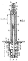
- Fig. 1 shows the cross section through a device for if necessary atomized application of a liquid, in particular Medium.
- the medium to be deployed is in the Syringe barrel 11 in which the piston 12 in the axial direction the syringe barrel is slidably mounted.
- the syringe barrel 11 opens into the discharge channel 13 through which through which the medium is applied when the plunger 14 by manual actuation of the piston 12 in the syringe barrel 11 shifted in the direction of the discharge channel 13 becomes.
- a cap 16 held in the the discharge channel 13 of the syringe barrel 11 opens.
- the Cap 16 has on its side facing away from the discharge channel 13 front tip a nozzle 31 as an outlet for the medium to be applied.
- the sealing element 17 provides a hermetic seal between nozzle 31 and mouth 32 of the discharge channel 13 at least as long as the device is not the first was pressed once.
- contamination becomes reliable or air access to that in the syringe barrel 11 stored medium to be discharged ensured. This is especially important if it is the person to be deployed Medium is a drug to be kept sterile. For example, this could be medication for migraines or but be vaccine serums that come to the patient through the nose Nasal mucosa are applied because they are special there can be well absorbed by the patient.
- the sealing element 17 can either be designed so that the first actuation, i.e. the first partial stroke, irreversible a channel between the mouth 32 of the delivery channel 13 and the nozzle 31 of the cap 16 releases. It is but also possible, the sealing element 17, for example an elastic mass, so that the channel between mouth 32 and nozzle 31 each for The duration of the partial stroke opens and then immediately again closes.
- the latter training has the advantage of continuing no air through the nozzle 31 to the discharge duct 13 can reach.
- the syringe barrel 11 has a widening 21 that adjusts supports the contact surface 20 of the housing 15.
- the contact surface 20 is a radial expansion of the housing 15, which advantageously at the same time as a finger system 19 for Support of the housing 15 in the user's hand during serves to actuate the device. This is at the same time ensured that the finger system 19 already before the first partial stroke - seen from the discharge channel 13 - Is behind the piston 12, making a stable and actuation-safe handling of the device advantageously is achieved.
- the shaft 33 of the housing 15 Surrounding the expansion 21 of the syringe barrel 11 protrudes the shaft 33 of the housing 15 towards the rear.
- the shaft 33 there are guide slots 23, in the locking lugs 24, which are formed on the actuating button 22, engage. Furthermore, the shaft 33 has at its rear end an end ring 25 closing the guide slots 23 on.
- the actuating button 22 is in its outer contour cup-shaped and through its locking lugs 24 in the Shank 33 held axially displaceable. The possible way of actuation s of the actuating button 22 between its illustrated Starting position and the end position is determined by the free length of the guide slots 23 in the Shank 33 of the housing 15 set. In actuation end position is the actuating button 22 with its front edge on the Widening 21 of the syringe barrel 11.
- the return spring 26 is arranged between the expansion 21 of the syringe barrel 11 and the The actuating button 22, the return spring 26 is arranged.
- the return spring 26 has two functions. By their bias it generates a between actuation pushers 22 and Syringe barrel 11 acting force, so that on the one hand Push button 22 of the housing 15 in its starting position is held, on the other hand also the Syringe barrel 11 against axial displacement in the housing 15 secured.
- the plunger 14 extends from the piston 12 to the bottom surface 35 of the actuating button 22.
- locking means 27 integrally formed, each about the actuation path s from each other are spaced and in the starting position of one Partial stroke on the locking edge 28, preferably by the Widening 21 of the syringe barrel 11 is formed.
- the locking means 27 form in cooperation with the Locking edge 28 one of the actuation of the actuation button 22nd counteracting pressure point, which preferably ensures will that with each actuation of the actuation button 22 such an actuating force is applied to it, that he is always in a continuous, uninterrupted activity by its entire actuation path from the actuation starting position is brought into the actuating end position.
- the driver 30 On its, the piston end facing away from the rear end Ram 14 on a driver 30, which is in front of the first Actuation in contact with the inside of the bottom surface 35 located.
- the driver 30 has a radial preload on it radially towards the Inner sleeve 29 on the bottom surface 35 of the actuation button 22 is formed and one of the actuation path s has appropriate length, applied.
- the number n of partial strokes in which this is in the syringe barrel 11 stored medium is distributed at shown device two. So that's also for Available volume for the medium in the syringe barrel given. The volume is determined from the inside diameter of the syringe barrel 11 and the displacement length of the Piston 12 between its starting position (as shown) and its end position if it is by the specified number n of Actuation paths s in the direction of the discharge channel 13 has been postponed. It is also possible that the individual Actuating elements have different actuation paths. This is due to the distance of the driver 30 from the Bottom surface 35 in front of the first and the inner sleeve 36 in front the second actuation stroke possible.
- the first Partial stroke may be greater than the second partial stroke, because during the first partial stroke, an empty path for opening the sealing element 17 is required. In the example shown, this can be done be achieved that the inner sleeve 29 by a predetermined Dimension is longer than the actuation path s of the actuation button 29 on the first partial stroke.
- the actuating button 22 is now operated, which in the Usually happens in that the actuating button 22 on the outside of the bottom surface 35 by the thumb of the A minimum force is applied to the user the actuation button 22 by the actuation path s from the Starting position - as shown - in the final operating position postponed.
- the Tappet 14 acted on and by the same actuation path s moved, whereby in the syringe barrel 11 of the piston 12th is shifted by the actuation path s.
- One of them displaced volume corresponding volume of medium is made the syringe barrel 11 through the delivery channel 13 spread out through the cap with the nozzle 31 and usually atomized through the nozzle 31.
- the return spring 26 In addition to its bias is the return spring 26 by Shortening their length further stretched. After completing the Actuation, the actuation button 22 is released. By between syringe barrel 11 and actuation button 22 applied force of the return spring 26 becomes the actuation button 22 returned to the starting position. By shaping the piston 12 and by the action the locking means 27 which are pressed into the syringe barrel 11 can be ensured that a move back of the plunger 14 together with the actuation button 22 does not take place. Rather, the drivers 30 slide along the inner sleeve 29.
- the drivers leave 30 the inner sleeve 29 and come into contact with the upper edge of the inner sleeve 36.
- the actuating force which acts on the actuating button 22 via transfer the inner sleeve 29 to the driver 30 of the plunger 14.
- a (slight) play between the inner sleeve upper edge 36 and driver 30 ensures a set that the driver 30 actually leave the inner sleeve 29 and enables on the other hand, desired travel differences of the first and the second actuation.
- the actuating button 22 by application a radially acting force is released from the housing 15 be in which the locking lugs 24 so far in the direction of the Tappet 14 are pushed in so that they the end ring 25th no longer reach behind. Then the actuation button 22 are pulled axially backwards.
- the for this purpose preferably on the bottom surface 35 of the actuation button 22 attached return spring 26 is also to the rear deducted.
- the syringe barrel 11 can be removed from the housing 15 can be removed.
- the cap is preferably used at the same time 16 removed. If the plunger 14 is not connected to the piston 12 is connected, the plunger 14 from the syringe barrel removed and used again.
- a possibly syringe barrel provided with a cap 16 and sealing element 17 11 with the piston 12 therein and new one, medium to be dispensed can now be inserted into the housing 15 become. Then, creating a preload on the Return spring 26 of the actuating button 22 again in the Shaft 33 of the housing 15 inserted. Once the push button 22 is held again by the end ring 25, can through the insertion opening 34 of the actuation button 22 through the plunger 14 can be used again.
- This Procedure has the advantage that the plunger 14 is not at Reinstall the actuation button 22 on the shaft 33 is moved far in the direction of the discharge channel 13 and so unintentionally part of the medium to be deployed is applied before the first operation.
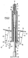
- FIG. 2 also shows a cross section through a Device for spraying a particular liquid medium.
- this device too Medium in the syringe barrel 11 ready.
- the Syringe barrel 11 opens into the discharge channel 13 its mouth 32, which of the introduced into the cap 16 Sealing element 17 to the nozzle 31 is closed.
- the cap 16 is by the union edge 18 of the housing 15 on Syringe barrel held.
- the syringe barrel 11 is also performed in the housing 15.
- On the application channel 13 facing away from the syringe barrel 11 is the Piston 12 is axially displaceable.
- the piston 12 will manually by means of the plunger 14 and the actuating button 22 operated.
- the housing 15 has the finger system 19.
- the Syringe barrel 11 is in the housing 15 with its expansion 21 supported on the contact surface 20 of the housing 15.
- On the widening 21 of the syringe barrel 11 is the locking disc 37 on.
- the return spring 26, which is used for the return of the actuation button 22 from the actuating end position to that shown Starting position ensures, arranged.
- the actuating button 22 is again cup-shaped and is guided in the shaft 33 of the housing 15. In the illustrated Starting position is the actuation button 22 held on the shaft 33 by means not shown, that he - seen from the discharge channel 13 - no further can be moved backwards.
- the cup-shaped push button 22 has the insertion opening on its bottom surface 35 34, through which the plunger 14 in the Syringe barrel 11 is insertable so that it is in contact the piston 12 arrives. In this situation the foremost are Carrier 30 on the locking disk 37. The next carriers 30 by the previous drivers 30 by the length s of a partial stroke are removed from the push bars 38 engaging the inner sleeve 29 of the actuating button 22. To enable partial strokes of different sizes, the Driver 30 also a smaller compared to the length s Have a distance that must be greater than s / 2, however not the next but one driver 30 is attacked. In in this case, the sliding webs 38 slide during an empty travel along the plunger 14 until the positive connection the driver 30 of the corresponding output stroke.
- the inner sleeve 29 surrounds the insertion opening 34 and protrudes from the bottom surface 35 of the actuation button 22 in Direction on the syringe barrel 11.
- the inner sleeve 29 has thrust webs 38, which in the movement space of the ram 14 protrude, but are so elastic that they during Return stroke of the actuation button 22 from the actuation end position in the actuating starting position as far radially outwards can be pressed that they over the driver 30 of Ram 14 can be moved away and so the range of motion for the relative movement between the shaft 14 and the actuating button Release 22 during the return stroke.
- the actuating button 22 If the actuating button 22 is actuated, one must first such force is applied that the foremost driver 30, which rests on the locking disc 37, the one locking edge forms, the locking disc 37 reversibly spreads so that the Plunger 14 can be moved into the syringe barrel 11 can. If this minimum actuation force is exceeded, then the shaft 14, of the push bars 38 of the actuation button 22 pushed further into the syringe barrel 11 in Moved towards the discharge channel 13 and pushes the piston 12 of the syringe barrel 11 with it. This happens until the actuating button 32 with its upper edge facing the syringe barrel 11 on the Widening 21 of the syringe barrel is present.
- the drivers 30 as thickenings, i.e. as radial cross-sectional extensions, of the plunger 14 formed.
- the plunger 14 points in the area the driver 30 has a frustoconical cross section, the cone tip towards the plunger 12 of the syringe barrel 11 shows.
- the push bars 38 are for power transmission on the plunger 14 on the bottom surface of the truncated cone the driver 30 on.
- FIG. 3 shows in a cross section the illustration of a Device for possibly spraying a particular liquid medium in which the subdivision of the actuation path the plunger of the syringe barrel in partial strokes by means of sliding shoes.
- a syringe barrel 11 has at its front end Delivery channel 13 on. This ends in the cap 16, the cap 16 having a nozzle 31 and the space between nozzle 31 and mouth 32 of the discharge channel 13 is closed by the sealing element 17.
- the syringe barrel 11 and the cap 16 are in the housing 15 through the Cap 18 held.
- the Piston 12 axially slidably mounted.
- the plunger 14 On the piston 12 is the plunger 14, the rear of the syringe barrel 11th protrudes, attached.
- the housing 15 extends over the Length of the syringe barrel 11, so that the expansion 21 of the Syringe barrel 11 on the contact surface 20 of the housing 15 be held clamped.
- the molded on the piston 12 of the syringe barrel 11 Ram 14 has on its rear, facing away from piston 12 End a collar 40 on by a cross-sectional expansion of the plunger 14 is formed.
- the cross-sectional expansion opens into the actuating button in the case shown 22, the application of an operating force by the Users allowed on the plunger 14.
- the finger system 19 points in its fastening area on the housing 15 which holds the syringe barrel 11 encased, a hinge - especially a film hinge 46 - on. From the finger system 19, seen radially outside of the film hinge, a lever 42 protrudes to the rear.
- the Lever 42 is from a first arm 43, which is in extends essentially in the axial direction to the rear and a second partial arm 44, which is connected to the first partial arm 43 a joint 45, in particular a film hinge, is connected, formed and has the slide shoe 41 at its other end on.
- the figure is on the left half of the figure shown, which results when there is no hand force on the Finger system 19 is exercised; is in the right half of the picture the case shown when a hand force on the finger system 19th acts.
- this is Film hinge 46 and the joint 45 biased such that the slide shoe 41 does not rest on the plunger 41 as long as no force is applied to the finger system 19.
- This has the advantage that the syringe cylinder is simple 11, possibly with the cap 16 attached to it, and the piston 12 with the plunger 14 together with the actuating button 22 in front of the Actuation inserted in the housing 15 and in the housing 21 are held by the shape of the contact surface 20 can. It is just as easy after the last partial stroke Remove the used syringe barrel 11.
- the housing 15 as well as the molded finger system 19 together with the levers 42 and the slide shoes 41 can be used for a variety of uses be used again during the syringe barrel 11 together with the cap 16 and the piston 12 and the tappet 14 and the actuating button 22, for example from hygienic Reasons, only one use is made at a time.
- a finger is placed on the finger system 19 and a force is applied thereby, the finger system 19 in the area of the radially outside of the film hinge 46 lies to the rear (facing away from the discharge duct 13 Side).
- the levers 42 with their first partial arms 43 and second partial arms 44 bring the sliding shoes 41 into contact to the tappet 14. If the actuation button is now actuated, the sliding shoes slide along the plunger 14 as long as until the collar 40 comes into contact with the sliding shoes 40 and jamming between collar 40, plunger 14 and sliding shoes 41 takes place. This prevents the plunger 14 from continuing than up to the collar 40 in the direction of the application channel 13 is pushed forward.
- the federal government 40 consists of one Cross-sectional expansion of the ram 14.
Abstract
Description
Aus der FR 88 00 454 ist eine Vorrichtung zum ggf. zerstäubten Ausbringen eines insbesondere flüssigen Mediums bekannt, bei dem das Medium in einem Spritzenzylinder aufbewahrt ist und das Medium über einen Ausbringungskanal ausgebracht werden kann. Hierzu ist im Spritzenzylinder ein Kolben angeordnet, der von einem Stößel beaufschlagbar ist, wobei der Kolben manuell betätigbar ist. Die manuelle Betätigung des Stößels erfolgt dabei über einen Betätigungsdrücker, der in einem Gehäuse geführt ist, das auch den Spritzenzylinder aufnimmt. Dabei sind an dem Gehäuse und an dem Betätigungsdrücker Führungsmittel vorgesehen, die die Betätigung des Betätigungsdrückers in der axialen Richtung des Spritzenzylinders begrenzen, wodurch der Gesamthub des Stößels im Spritzenzylinder in mehrere definierte Teilhübe unterteilt wird. Um am Ende eines Teilhubes den nächsten Teilhub ausführen zu können ist es erforderlich, den Betätigungsdrücker gegenüber dem Spritzenzylinder bzw. gegenüber dem Gehäuse in dem der Spritzenzylinder angeordnet ist, zu verdrehen. FR 88 00 454 describes a device for atomizing, if necessary Application of a particularly liquid medium, where the medium is stored in a syringe barrel and the medium is discharged through a discharge channel can be. For this there is a piston in the syringe barrel arranged, which can be acted upon by a plunger, wherein the piston can be operated manually. Manual operation the plunger takes place via an actuation button, the is guided in a housing that also the syringe barrel records. Here are on the housing and on the actuating button Guide means provided that the actuation of the Actuation pusher in the axial direction of the syringe barrel limit, whereby the total stroke of the ram in Syringe barrel divided into several defined partial strokes becomes. To execute the next partial stroke at the end of a partial stroke To be able to, it is necessary to be able to use the push button compared to the syringe barrel or the housing in which the syringe barrel is arranged to twist.
Daneben ist aus der EP 0 334 349 A1 eine Vorrichtung zum Ausbringen eines Mediums bekannt, bei der der Stößel eines Spritzenzylinders über einen Betätigungsdrücker betätigt wird. Der Betätigungsdrücker wird dabei in einem Gehäuse geführt, das als Aufnahme für den Spritzenzylinder dient. Dabei sind an dem Gehäuse Führungsnocken ausgebildet, die in einer am Betätigungsdrücker ausgeformten Kulissenbahn geführt werden. Die Kulissenbahn ist so geformt, daß der Betätigungsweg des Betätigungsdrückers in mehrere Teilhübe unterteilt wird. Dies geschieht entweder dadurch, daß die Kulissenbahn treppenförmig verläuft, so daß zwischen zwei Teilhüben des Betätigungsdrückers ein Verdrehen des Betätigungsdrückers gegenüber dem Gehäuse erforderlich ist oder aber indem die Kulissenbahn überdrückbare Raststellen aufweist, die die in der Kulissenbahn geführte Nocke in einer Endlage eines Teilhubes so lange halten, bis die Betätigungskraft eine Haltekraft übersteigt. In dem letzteren Falle kann die Kulissenbahn auch linear ausgebildet sein.In addition, EP 0 334 349 A1 describes a device for Application of a medium known, in which the plunger of a Syringe barrel operated via an actuation button becomes. The actuation button is in a housing led, which serves as a receptacle for the syringe barrel. Guide cams are formed on the housing, which in a slide formed on the actuating button become. The slide track is shaped so that the actuation path of the actuation button divided into several partial strokes becomes. This happens either because the backdrop is staircase-shaped, so that between two partial strokes of the Actuation button a turning of the actuation button compared to the housing is required or by the Scenery track overpressurable rest stops, which in the cam track guided in an end position of a Hold the partial stroke until the actuating force is one Holding force exceeds. In the latter case, the Slide track can also be linear.
Bei Vorrichtungen zum Ausbringen von Medien, bei denen ein Verdrehen des Betätigungsdrückers bzgl. dem Gehäuse erforderlich ist, um aufeinanderfolgende Teilhübe durchzuführen, ist es nachteilig, daß die Möglichkeit einer Einhandbetätigung nicht besteht. Zum Verdrehen des Betätigungsdrückers bzgl. dem Gehäuse ist es erforderlich, mit beiden Händen die Vorrichtung zu halten. Jedoch haben die gestuften Führungen den Vorteil, daß ein versehentliches aneinandergereihtes Durchführen zweier Teilhübe in einer Bewegung nicht möglich ist. Die Ausführung mit einer linearen Kulissenbahn und durch Überwindung einer Haltekraft überdrückbare Raststellen zur Unterteilung der Ausbringung des Mediums in mehrere Teilhübe, eröffnet zwar die Möglichkeit der Einhandbetätigung, es besteht hier aber die Gefahr, daß unbeabsichtigt mehrere Teilhübe in ununterbrochener Betätigung hintereinander ausgeführt werden.In devices for dispensing media in which a It is necessary to turn the actuation button with respect to the housing in order to carry out successive partial strokes it is disadvantageous that the possibility of one-hand operation does not exist. To turn the actuation button with respect to the case it is necessary to use both hands Hold device. However, the tiered guides the advantage that an accidental lined up It is not possible to perform two partial strokes in one movement is. The version with a linear slide track and locking points that can be suppressed by overcoming a holding force to divide the output of the medium into several Partial strokes, opens the possibility of one-hand operation, however, there is a risk that this could be unintentional several partial strokes in continuous operation in a row be carried out.
Aufgabe der Erfindung ist es, eine einhandbetätigbare Vorrichtung zum Ausbringen eines flüssigen Mediums zu schaffen, bei der sichergestellt ist, daß Teilhübe nicht unbeabsichtigt ununterbrochen hintereinander durchgeführt werden.The object of the invention is a one-hand operated device to create a liquid medium, which ensures that partial strokes are not unintentional be carried out continuously one after the other.
Diese Aufgabe wird durch Vorrichtungen gemäß der unabhängigen Ansprüche gelöst.This task is accomplished by devices according to the independent Claims resolved.
Eine erste erfindungsgemäße Vorrichtung sieht hierfür vor, daß ein Betätigungsdrücker an dem Stößel angreift, der den in dem Spritzenzylinder verschiebbaren Kolben betätigt, wobei der Betätigungsweg des Betätigungsdrückers zwischen einer Betätigungsausgangs- und Betätigungsendlage so begrenzt ist, daß der daraus resultierende Ausbringungshub des Kolbens dem Maß entspricht, das für das Ausbringen einer Teilcharge benötigt wird.A first device according to the invention provides for this that an actuating button on the plunger engages the in the syringe barrel slidable piston operated, wherein the actuation path of the actuation button between one Actuating starting and actuating end position is limited that the resulting discharge stroke of the piston Dimension corresponds to that for the application of a partial batch is needed.
Gemäß vorteilhaften Ausbildungen der Vorrichtung wird eine Rückstellfeder zum Zurückführen des Betätigungsdrückers aus der Betätigungsendlage in die Betätigungsausgangslage vorgesehen. An dem auf den Kolben des Spritzenzylinders einwirkenden Stößel sind Mitnehmer angeformt, die lediglich in Richtung des Ausbringunsghubes eine kraftschlüssige Verbindung zwischen Betätigungsdrücker und Stößel herstellen. Zusätzlich können gemäß vorteilhafter Ausgestaltung an dem Stößel auch Rastmittel angeformt sein, die in Betätigungsausgangslage an einer Rastkante anliegen und die durch Überwinden einer Mindestbetätigungskraft des Betätigungsdrückers überdrückbar sind. Besonders vorteilhaft kann es sein, daß die Mitnehmer derart ausgebildet sind, daß die Mitnehmer eines Ausbringungshubes als Rastmittel eines nachfolgenden Ausbringungshubes dienen.According to advantageous embodiments of the device Return spring to return the actuation button the actuation end position is provided in the actuation starting position. On the one acting on the plunger of the syringe barrel Tappets are formed on drivers that only point in the direction of the output stroke is a non-positive connection between the push button and the plunger. In addition can also according to an advantageous embodiment on the plunger Snap-in means are molded on, which are in the starting position a rest edge and by overcoming one Minimum actuation force of the actuation button can be suppressed are. It can be particularly advantageous that the driver are designed such that the drivers of a delivery stroke as a locking means of a subsequent delivery stroke serve.
Gemäß einer Ausgestaltung der Erfindung sind die Mitnehmer als Verdickungen des Stößels ausgebildet, besonders vorteilhaft ist es, den Abschnitt des Stößels, der als Mitnehmer ausgebildet ist, als Kegelstumpf auszubilden, wobei die gedachte Spitze des Kegelstumpfes in Richtung des Kolbens des Spritzenzylinders liegt. Weitere vorteilhafte Ausgestaltungen der Vorrichtung zum Ausbringen eines Mediums können den weiteren Unteransprüchen entnommen werden.According to one embodiment of the invention, the drivers formed as a thickening of the plunger, particularly advantageous is the section of the ram that acts as the driver is designed to form as a truncated cone, the imaginary tip of the truncated cone towards the piston of the Syringe barrel lies. Further advantageous configurations the device for dispensing a medium can further subclaims can be found.
Eine zweite Vorrichtung zum Ausbringen eines Mediums wird ebenfalls aus einem Spritzenzylinder gebildet, in dem ein Kolben angeordnet ist, der über einen Stößel betätigbar ist. Hierzu liegt ein Gleitschuh an dem Stößel in einem Bereich außerhalb des Spritzenzylinders an und der Stößel weist wenigstens einen Bund auf, wobei in Betätigungsendlage eines der Ausbringer einer Teilcharge entsprechenden Betätigungshubes der Bund in Anlage mit dem Gleitschuh gelangt.A second device for dispensing a medium is also formed from a syringe barrel in which a Piston is arranged, which is actuated by a plunger. For this purpose, a slide shoe lies on the plunger in one area outside the syringe barrel and the plunger points at least one collar, one in the end position the operator of a partial batch of the corresponding actuation stroke the collar comes into contact with the slide shoe.
Gemäß vorteilhafter Ausgestaltung dieser Ausführungsform wird der Gleitschuh in Betätigungsendlage am Spritzenzylinder abgestützt. Eine weitere vorteilhafte Ausgestaltung ist darin zu sehen, daß der Bund durch eine Durchmesservergrößerung des Stößels gebildet wird. Weitere vorteilhafte Ausgestaltungen dieser Ausführungsform befassen. Weitere vorteilhafte Ausgestaltungen dieser Ausführungsform befassen sich mit der Anlenkung des Gleitschuhs.According to an advantageous embodiment of this embodiment the slide shoe in the actuating end position on the syringe barrel supported. Another advantageous embodiment is therein to see that the federal government by increasing the diameter of the Ram is formed. Further advantageous configurations deal with this embodiment. Further advantageous configurations this embodiment deal with the Articulation of the slide shoe.
Weitere Unteransprüche befassen sich mit vorteilhaften Ausgestaltungen beider Ausführungsformen. Further subclaims deal with advantageous ones Embodiments of both embodiments.
Die vorstehenden und weitere Merkmale gehen außer aus den Ansprüchen auch aus der Beschreibung und den Zeichnungen hervor, wobei die einzelnen Merkmale jeweils für sich allein oder zu mehreren in Form von Unterkombinationen bei einer Ausführungsform der Erfindung und auf anderen Gebieten verwirklicht sein und vorteilhafte sowie für sich schutzfähige Ausführungen darstellen können, für die hier Schutz beansprucht wird. Die Unterteilung der Anmeldung in einzelne Abschnitte sowie Zwischen-Überschriften beschränken die unter diesen gemachten Aussagen nicht in ihrer Allgemeingültigkeit.The above and other features go beyond the Claims also from the description and the drawings , the individual features each individually or more in the form of sub-combinations in one Embodiment of the invention and in other fields be realized and advantageous as well as protectable Can represent designs for which protection here is claimed. The division of the registration into individual Sections and sub-headings limit the below these statements are not generally valid.
Ausführungsbeispiele der Erfindung sind in den Zeichnungen dargestellt und werden im folgenden näher erläutert. In den Zeichnungen zeigen:
- Fig. 1
- in Schnittdarstellung ein erstes Ausführungsbeispiel einer Vorrichtung, bei der der Betätigungsweg des Betätigungsdrückers auf das für das Ausbringen einer Teilcharge benötigten Hub begrenzt ist;
- Fig. 2
- den Querschnitt durch ein zweites Ausführungsbeispiel mit begrenztem Betätigungsweg eines Betätigungsdrückers und
- Fig. 3
- die Schnittdarstellung eines Ausführungsbeispiels, bei dem der Weg des Stößels durch an Stößel anliegende Gleitschuhe begrenzt wird.
- Fig. 1
- a sectional view of a first embodiment of a device in which the actuation path of the actuation button is limited to the stroke required for the discharge of a partial batch;
- Fig. 2
- the cross section through a second embodiment with limited actuation path of an actuation button and
- Fig. 3
- the sectional view of an embodiment in which the path of the plunger is limited by sliding shoes abutting the plunger.
Die Fig. 1 zeigt den Querschnitt durch eine Vorrichtung zum
ggf. zerstäubten Ausbringen eines insbesondere flüssigen
Mediums. Das auszubringende Medium befindet sich in dem
Spritzenzylinder 11, in dem der Kolben 12 in axialer Richtung
des Spritzenzylinders verschiebbar gelagert ist. Der Spritzenzylinder
11 mündet in dem Ausbringungskanal 13, durch den
hindurch das Medium ausgebracht wird, wenn über den Stößel 14
durch manuelle Betätigung der Kolben 12 im Spritzenzylinder
11 in Richtung auf den Ausbringungskanal 13 hin verschoben
wird.Fig. 1 shows the cross section through a device for
if necessary atomized application of a liquid, in particular
Medium. The medium to be deployed is in the
Syringe
Auf der Seite des Ausbringungskanals 13 wird über die Überwurfkante
18 des Gehäuses 15 eine Kappe 16 gehalten, in die
der Ausbringungskanal 13 des Spritzenzylinders 11 mündet. Die
Kappe 16 weist an ihrer dem Ausbringungskanal 13 abgewandten,
vorderen Spitze eine Düse 31 als Austrittsöffnung für das
auszubringende Medium auf. Zwischen Kappe 16 und Mündung 32
des Ausbringungskanals 13 befindet sich das Dichtelement 17.
Das Dichtelement 17 stellt eine hermetische Abdichtung
zwischen Düse 31 und Mündung 32 des Ausbringungskanals 13
zumindest solange dar, wie die Vorrichtung nicht zum ersten
mal betätigt wurde. Dadurch wird zuverlässig eine Verkeimung
oder ein Luftzutritt zu dem in dem Spritzenzylinder 11
aufbewahrten auszubringenden Medium sichergestellt. Dies ist
besonders dann wichtig, wenn es sich bei dem auszubringenden
Medium um ein steril aufzubewahrendes Arzneimittel handelt.
Dies könnten beispielsweise Medikamente gegen Migräne oder
aber Impfseren sein, die dem Patienten über die Nase auf die
Nasenschleimhäute appliziert werden, da sie dort besonders
gut vom Patienten absorbiert werden können. On the side of the
Das Dichtelement 17 kann dabei entweder so ausgebildet sein,
daß es bei der ersten Betätigung, also dem ersten Teilhub,
irreversibel einen Kanal zwischen Mündung 32 des Ausbringungskanals
13 und der Düse 31 der Kappe 16 freigibt. Es ist
aber auch möglich, das Dichtelement 17, beispielsweise aus
einer elatischen Masse, so auszubilden, daß der Kanal
zwischen Mündung 32 und Düse 31 sich jeweils nur für die
Dauer des Teilhubes öffnet und anschließend sofort wieder
verschließt. Letztere Ausbildung hat den Vorteil, daß weiterhin
keine Luft über die Düse 31 zum Ausbringungskanal 13
gelangen kann.The
Am dem Ausbringungskanal 13 gegenüberliegenden Ende weist
der Spritzenzylinder 11 eine Aufweitung 21 auf, die sich an
der Anlagefläche 20 des Gehäuses 15 abstützt. Die Anlagefläche
20 wird durch eine radiale Aufweitung des Gehäuses 15,
die vorteilhafterweise gleichzeitig als Fingeranlage 19, zur
Abstützung des Gehäuses 15 in der Hand des Benutzers während
der Betätigung der Vorrichtung dient, gebildet. Dadurch ist
gleichzeitig sichergestellt, daß die Fingeranlage 19 schon
vor dem ersten Teilhub - vom Ausbringungskanal 13 her gesehen
- hinter dem Kolben 12 liegt, wodurch eine stabile und
betätigungssichere Handhabung der Vorrichtung vorteilhafterweise
erreicht wird.At the end opposite the
Die Aufweitung 21 des Spritzenzylinders 11 umgebend, ragt
der Schaft 33 des Gehäuses 15 nach hinten ab. In dem Schaft
33 befinden sich Führungsschlitze 23, in die Rastnasen 24,
die an dem Betätigungsdrücker 22 angeformt sind, eingreifen.
Des weiteren weist der Schaft 33 an seinem hinteren Ende
einen die Führungsschlitze 23 abschließenden Abschlußring 25
auf. Der Betätigungsdrücker 22 ist in seiner Außenkontur
napfförmig ausgebildet und durch seine Rastnasen 24 in dem
Schaft 33 axial verschiebbar gehalten. Der mögliche Betätigungsweg
s des Betätigungsdrückers 22 zwischen seiner dargestellten
Betätigungsausgangslage und der Betätigungsendlage
wird durch die freie Länge der Führungsschlitze 23 in dem
Schaft 33 des Gehäuses 15 festgelegt. In Betätigungsendlage
liegt der Betätigungsdrücker 22 mit seiner Vorderkante an der
Aufweitung 21 des Spritzenzylinders 11 an.Surrounding the
Zwischen der Aufweitung 21 des Spritzenzylinders 11 und dem
Betätigungsdrücker 22 ist die Rückstellfeder 26 angeordnet.
Die Rückstellfeder 26 hat zwei Funktionen. Durch ihre Vorspannung
erzeugt sie eine zwischen Betätigungsdrücker 22 und
Spritzenzylinder 11 wirkende Kraft, so daß einerseits der
Betätigungsdrücker 22 des Gehäuses 15 in seiner Betätigungsausgangslage
gehalten wird, andererseits wird auch der
Spritzenzylinder 11 gegen axiales Verschieben im Gehäuse 15
gesichert.Between the
Der Stößel 14 reicht vom Kolben 12 bis zu der Bodenfläche 35
des Betätigungsdrückers 22. An dem Stößel 14 sind Rastmittel
27 angeformt, die jeweils um den Betätigungsweg s voneinander
beabstandet sind und die in Betätigungsausgangslage eines
Teilhubes an der Rastkante 28, die vorzugsweise durch die
Aufweitung 21 des Spritzenzylinders 11 gebildet wird, anliegen.
Die Rastmittel 27 bilden im Zusammenwirken mit der
Rastkante 28 einen der Betätigung des Betätigungsdrückers 22
entgegenwirkenden Druckpunkt, wodurch vorzugsweise sichergestellt
wird, daß bei jeder Betätigung des Betätigungsdrückers
22 an ihm eine derartige Betätigungskraft aufgebracht wird,
daß er immer in einer durchgehenden, ununterbrochenen Betätigung
um seinen gesamten Betätigungsweg von der Betätigungsausgangslage
in die Betätigungsendlage verbracht wird. An
seinem, dem Kolben 12 abgewandten, hinteren Ende weist der
Stößel 14 einen Mitnehmer 30 auf, der sich vor der ersten
Betätigung in Anlage mit der Innenseite der Bodenfläche 35
befindet. Durch eine Einkerbung weist der Mitnehmer 30 eine
radiale Vorspannung auf, die ihn radial in Richtung auf die
Innenhülse 29, die an der Bodenfläche 35 des Betätigungsdrückers
22 angeformt ist und eine dem Betätigungsweg s
entsprechende Länge aufweist, beaufschlagt.The
Die Anzahl n der Teilhübe, in denen das im Spritzenzylinder
11 vorgehaltene Medium ausgebracht wird, beträgt bei der
dargestellten Vorrichtung zwei. Somit ist auch das zur
Verfügung stehende Volumen für das Medium im Spritzenzylinder
vorgegeben. Das Volumen bestimmt sich aus dem Innendurchmesser
des Spritzenzylinders 11 und der Verschiebelänge des
Kolbens 12 zwischen seiner Ausgangslage (wie dargestellt) und
seiner Endlage, wenn er um die vorgegebene Anzahl n von
Betätigungswegen s in Richtung auf den Ausbringungskanal 13
hin verschoben wurde. Es ist auch möglich, daß die einzelnen
Betätigungselemente unterschiedliche Betätigungswege aufweisen.
Dies ist über den Abstand des Mitnehmers 30 zu der
Bodenfläche 35 vor dem ersten und zu der Innenhülse 36 vor
dem zweiten Betätigungshub möglich. Insbesondere kann, um
gleiche Ausbringungsvolumina sicherzustellen, der erste
Teilhub größer sein als der zweite Teilhub, da während des
ersten Teilhubes ein Leerweg zum Öffnen des Dichtelements 17
erforderlich ist. Im dargestellten Beispiel kann dies dadurch
erreicht werden, daß die Innenhülse 29 um ein vorgegebenes
Maß länger ist als der Betätigungsweg s des Betätigungsdrückers
29 beim ersten Teilhub.The number n of partial strokes in which this is in the
Wird der Betätigungsdrücker 22 nunmehr betätigt, was in der
Regel dadurch geschieht, daß der Betätigungsdrücker 22 auf
der Außenseite der Bodenfläche 35 durch den Daumen des
Benutzers mit einer Mindestkraft beaufschlagt wird, so wird
der Betätigungsdrücker 22 um den Betätigungsweg s von der
Betätigungsausgangslage - wie dargestellt - in die Betätigungsendlage
verschoben. Über den Mitnehmer 30 wird der
Stößel 14 beaufschlagt und um den gleichen Betätigungsweg s
verschoben, wodurch in dem Spritzenzylinder 11 der Kolben 12
um den Betätigungsweg s verschoben wird. Ein dem dabei
verdrängten Volumen entsprechendes Volumen an Medium wird aus
dem Spritzenzylinder 11 durch den Ausbringungskanal 13
hindurch über die Kappe mit der Düse 31 hinaus ausgebracht
und üblicherweise durch die Düse 31 zerstäubt. Zusätzlich zu
ihrer Vorspannung wird dabei die Rückstellfeder 26 durch
Verkürzung ihrer Länge weiter gespannt. Nach Beendigung der
Betätigung wird der Betätigungsdrücker 22 losgelassen. Durch
die zwischen Spritzenzylinder 11 und Betätigungsdrücker 22
aufgebrachte Kraft der Rückstellfeder 26 wird der Betätigungsdrücker
22 in die Betätigungsausgangslage zurück verbracht.
Durch Formgebung des Kolbens 12 und durch die Wirkung
der Rastmittel 27, die in den Spritzenzylinder 11 hineingedrückt
wurden, kann sichergestellt werden, daß ein Zurückbewegen
des Stößels 14 zusammen mit dem Betätigungsdrücker
22 nicht stattfindet. Vielmehr gleiten die Mitnehmer 30
entlang der Innenhülse 29. Sobald der Betätigungsdrücker 22
wieder die Betätigungsausgangslage, die durch den Abschlußring
25 definiert wird, erreicht, verlassen die Mitnehmer 30
die Innenhülse 29 und gelangen in Anlage mit der Innenhülsenoberkante
36. Bei der nächsten Betätigung wird die Betätigungskraft,
die auf den Betätigungsdrücker 22 einwirkt, über
die Innenhülse 29 auf die Mitnehmer 30 des Stößels 14 übertragen.If the
Ein (geringfügiges) Spiel zwischen Innenhülsenoberkante 36
und Mitnehmer 30 stellt einersetis sicher, daß die Mitnehmer
30 tatsächlich die Innenhülse 29 verlassen und ermöglicht
andererseits erwünschte Hubwegdifferenzen der ersten und der
zweiten Betätigung. A (slight) play between the inner sleeve
Um eine vorteilhafte große Widerverwertbarkeit von Teilen zu
erreichen, kann der Betätigungsdrücker 22 durch Aufbringen
einer radial wirkenden Kraft von dem Gehäuse 15 gelöst
werden, in dem die Rastnasen 24 soweit in Richtung auf den
Stößel 14 hineingedrückt werden, daß sie den Abschlußring 25
nicht mehr hintergreifen. Danach kann der Betätigungsdrücker
22 axial nach hinten abgezogen werden. Die zu diesem Zweck
vorzugsweise an der Bodenfläche 35 des Betätigungsdrückers 22
befestigte Rückstellfeder 26 wird ebenfalls nach hinten
abgezogen. Nun kann der Spritzenzylinder 11 aus dem Gehäuse
15 entfernt werden. Vorzugsweise wird gleichzeitig die Kappe
16 entfernt. Sofern der Stößel 14 nicht mit dem Kolben 12
verbunden ist, kann auch der Stößel 14 vom Spritzenzylinder
herausgenommen werden und erneut verwendet werden. Ein ggf.
mit einer Kappe 16 und Dichtelement 17 versehener Spritzenzylinder
11 mit dem darin befindlichen Kolben 12 und neuem,
auszubringenden Medium kann nun in das Gehäuse 15 eingesetzt
werden. Danach wird unter Erzeugen einer Vorspannung an der
Rückstellfeder 26 der Betätigungsdrücker 22 wieder in den
Schaft 33 des Gehäuses 15 eingesetzt. Sobald der Betätigungsdrücker
22 wieder durch den Abschlußring 25 gehalten wird,
kann durch die Einführungsöffnung 34 des Betätiungsdrückers
22 hindurch der Stößel 14 wieder eingesetzt werden. Diese
Vorgehensweise hat den Vorteil, daß der Stößel 14 nicht beim
Wiederansetzen des Betätigungsdrückers 22 an dem Schaft 33 zu
weit in Richtung des Ausbringungskanals 13 verschoben wird
und so unbeabsichtigt ein Teil des auszubringenden Mediums
schon vor der ersten Betätigung ausgebracht wird. Im Hinblick
auf die Sicherung der Vorrichtung vor unbeabsichtigter
Betätigung, kann es auch von Vorteil sein, den Stößel 14 erst
unmittelbar vor einer weiteren Benutzung der Vorrichtung
wieder durch die Einführungsöffnung 34 hindurch in das
Gehäuse 15 und den Spritzenzylinder 11 hin einzusetzen, da
ohne ihn ein unbeabsichtigtes Betätigen der Vorrichtung nicht
möglich ist.To have an advantageous large recyclability of parts
can reach, the
Die Fig. 2 zeigt ebenfalls einen Querschnitt durch eine
Vorrichtung zum zerstäubten Ausbringen eines insbesondere
flüssigen Mediums. Bei dieser Vorrichtung wird ebenfalls das
Medium in dem Spritzenzylinder 11 bereitgehalten. Der
Spritzenzylinder 11 mündet in dem Ausbringungskanal 13 mit
seiner Mündung 32, die von dem in der Kappe 16 eingebrachten
Dichtelement 17 zur Düse 31 hin verschlossen wird. Die Kappe
16 wird durch die Überwurfkante 18 des Gehäuses 15 am
Spritzenzylinder gehalten. Der Spritzenzylinder 11 ist
ebenfalls im Gehäuse 15 geführt. Auf der dem Ausbringungskanal
13 abgewandten Seite des Spritzenzylinders 11 ist der
Kolben 12 axial verschiebbar angeordnet. Der Kolben 12 wird
mittels des Stößels 14 und dem Betätigungsdrücker 22 manuell
betätigt. Zur Aufbringung einer Kraft auf den Betätigungsdrücker
22 weist das Gehäuse 15 die Fingeranlage 19 auf. Der
Spritzenzylinder 11 ist in dem Gehäuse 15 mit seiner Aufweitung
21 an der Anlagefläche 20 des Gehäuses 15 abgestützt. An
der Aufweitung 21 des Spritzenzylinders 11 liegt die Rastscheibe
37 an. Zwischen Rastscheibe 37 - oder Aufweitung
21 - und der Bodenfläche 35 des Betätigungsdrückers 22 ist
die Rückstellfeder 26, die für die Rückführung des Betätigungsdrückers
22 aus der Betätigungsendlage in die dargestellte
Betätigungsausgangslage sorgt, angeordnet. Der
Betätigungsdrücker 22 ist wiederum napfförmig ausgebildet und
wird in dem Schaft 33 des Gehäuses 15 geführt. In der dargestellten
Betätigungsausgangslage wird der Betätigungsdrücker
22 über nicht dargestellte Mittel am Schaft 33 so gehalten,
daß er - vom Ausbringungskanal 13 her gesehen - nicht weiter
nach hinten wegbewegt werden kann. Der napfförmige Betätigungsdrücker
22 weist auf seiner Bodenfläche 35 die Einführungsöffnung
34 auf, durch die hindurch der Stößel 14 in den
Spritzenzylinder 11 so einführbar ist, daß er in Anlage an
den Kolben 12 gelangt. In dieser Lage liegen die vordersten
Mitnehmer 30 an der Rastscheibe 37 an. Die nächsten Mitnehmer
30, die von den vorhergehenden Mitnehmern 30 um die Länge s
eines Teilhubes entfernt sind, werden von den Schubstegen 38
der Innenhülse 29 des Betätigungsdrückers 22 hintergriffen.
Um unterschiedlich große Teilhübe zu ermöglichen, können die
Mitnehmer 30 auch einen gegenüber der Länge s geringeren
Abstand aufweisen, der jedoch größer sein muß als s/2, damit
nicht der übernächste Mitnehmer 30 hintergriffen wird. In
diesem Fall gleiten die Schubstege 38 während eines Leerweges
entlang dem Stößel 14 bis die kraftschlüssige Verbindung zu
dem Mitnehmer 30 des entsprechenden Ausbringungshubes entsteht.
Die Innenhülse 29 umgibt die Einführungsöffnung 34 und
ragt von der Bodenfläche 35 des Betätigungsdrückers 22 in
Richtung auf den Spritzenzylinder 11 ab. Die Innenhülse 29
weist Schubstege 38 auf, die in den Bewegungsraum des Stößels
14 hineinragen, jedoch so elastisch sind, daß sie während des
Rückhubes des Betätigungsdrückers 22 von der Betätigungsendlage
in die Betätigungsausgangslage soweit radial nach außen
gedrückt werden können, daß sie über die Mitnehmer 30 des
Stößels 14 hinweg bewegt werden können und so den Bewegungsraum
für die Relativbewegung zwischen Schaft 14 und Betätigungsdrücker
22 während des Rückhubes freigeben.2 also shows a cross section through a
Device for spraying a particular
liquid medium. In this device, too
Medium in the
Wird der Betätigungsdrücker 22 betätigt, so muß zunächst eine
solche Kraft aufgebracht werden, daß der vorderste Mitnehmer
30, der an der Rastscheibe 37 anliegt, die eine Rastkante
bildet, die Rastscheibe 37 reversibel so spreizt, daß der
Stößel 14 in den Spritzenzylinder 11 hineinbewegt werden
kann. Ist diese Mindestbetätigungskraft überschritten, so
wird der Schaft 14, von den Schubstegen 38 des Betätigungsdrückers
22 geschoben, weiter in den Spritzenzylinder 11 in
Richtung auf den Ausbringungskanal 13 hineinbewegt und
schiebt dabei den Kolben 12 des Spritzenzylinders 11 mit.
Dies geschieht soweit, bis der Betätigungsdrücker 32 mit
seiner dem Spritzenzylinder 11 zugewandten Oberkante an der
Aufweitung 21 des Spritzenzylinders anliegt. In dieser Lage
sind die ersten Mitnehmer 30 in den Spritzenzylinder 11
hineinbewegt, die zweiten Mitnehmer 30 liegen an der Rastscheibe
37 an, die Rückstellfeder 26 ist komprimiert. Wird
der Betätigungsdrücker 22 nun losgelassen, so sorgt die
Rückstellfeder 26 dafür, daß er wieder in die dargestellte
Betätigungsausgangslage zurückbewegt wird. Dabei streifen die
Schubstege 38 entlang dem Stößel 14, bis sie von der Vorderkante
der dritten Mitnehmer 30 gespreizt werden und so über
diese hinweg bewegt werden. Sobald die Schubstege 38 über die
Mitnehmer 30 hinwegbewegt sind, legen sie sich wieder an den
Stößel 14 an und hintergreifen die dritten Mitnehmer 30. Die
zweiten Mitnehmer 30 dienen für den zweiten und im dargestellten
Beispiel letzten Teilhub als Rastmittel, die das
Aufbringen der erforderlichen Mindestbetätigungskraft für den
weiteren Teilhub sicherstellen.If the
Im dargestellten Ausführungsbeispiel sind die Mitnehmer 30
als Verdickungen, d.h. als radiale Querschnittserweiterungen,
des Stößels 14 ausgebildet. Der Stößel 14 weist im Bereich
der Mitnehmer 30 einen kegelstumpfförmigen Querschnitt auf,
wobei die Kegelspitze in Richtung des Kolbens 12 des Spritzenzylinders
11 zeigt. Die Schubstege 38 liegen zur Kraftübertragung
auf den Stößel 14 an der Bodenfläche des Kegelstumpfes
der Mitnehmer 30 an.In the illustrated embodiment, the
Um eine größere Anzahl von Teilhüben zu ermöglichen, ist es
lediglich erforderlich, den Stößel 14 nach hinten zu verlängern
und ihn mit weiteren Mitnehmern 30 zu versehen. Gleichzeitig
muß der mögliche Weg des Kolbens 12 im Spritzenzylinder
11 einen entsprechenden Weg zurücklegen können. To enable a larger number of partial strokes, it is
only necessary to extend the
Die Fig. 3 zeigt in einem Querschnitt die Darstellung einer Vorrichtung zum ggf. zerstäubten Ausbringen eines insbesondere flüssigen Mediums, bei dem die Unterteilung des Betätigungsweges des Kolbens des Spritzenzylinders in Teilhübe mittels Gleitschuhen erfolgt.3 shows in a cross section the illustration of a Device for possibly spraying a particular liquid medium in which the subdivision of the actuation path the plunger of the syringe barrel in partial strokes by means of sliding shoes.
Ein Spritzenzylinder 11 weist an seinem vorderen Ende den
Ausbringungskanal 13 auf. Dieser mündet in der Kappe 16,
wobei die Kappe 16 eine Düse 31 aufweist und wobei der Raum
zwischen Düse 31 und Mündung 32 des Ausbringungskanals 13
durch das Dichtelement 17 verschlossen ist. Der Spritzenzylinder
11 und die Kappe 16 sind in dem Gehäuse 15 durch die
Überwurfkante 18 gehalten. In dem Spritzenzylinder 11 ist der
Kolben 12 axial verschiebbar gelagert. An dem Kolben 12 ist
der Stößel 14, der nach hinten aus dem Spritzenzylinder 11
hinausragt, befestigt. Das Gehäuse 15 erstreckt sich über die
Länge des Spritzenzylinders 11, so daß die Aufweitung 21 des
Spritzenzylinders 11 an der Anlagefläche 20 des Gehäuses 15
klemmend gehalten werden.A
Der an dem Kolben 12 des Spritzenzylinders 11 angeformte
Stößel 14 weist auf seinem dem Kolben 12 abegwandten, hinteren
Ende einen Bund 40 auf, der durch eine Querschnittserweiterung
des Stößels 14 gebildet wird. Die Querschnittserweiterung
mündet im dargestellten Fall in dem Betätigungsdrücker
22, der das Aufbringen einer Betätigungskraft durch den
Benutzer auf den Stößel 14 erlaubt.The molded on the
An dem Gehäuse 15 sind seitlich abragende Fingeranlagen 19
angeformt. Dabei weist die Fingeranlage 19 in ihrem Befestigungsbereich
an dem Gehäuse 15, das den Spritzenzylinder 11
ummantelt, ein Scharnier - insbesondere ein Filmscharnier
46 - auf. Von der Fingeranlage 19, radial gesehen außerhalb
des Filmscharniers, ragt ein Hebel 42 nach hinten ab. Der
Hebel 42 wird aus einem ersten Teilarm 43, der sich im
wesentlichen in axialer Richtung nach hinten erstreckt und
einem zweiten Teilarm 44, der mit dem ersten Teilarm 43 über
ein Gelenk 45, insbesondere ein Filmscharnier, verbunden ist,
gebildet und weist an seinem anderen Ende den Gleitschuh 41
auf.On the
In der Figur ist auf der linken Figurenhälfte die Lage
dargestellt, die sich ergibt, wenn keine Handkraft auf die
Fingeranlage 19 ausgeübt wird; in der rechten Bildhälfte ist
der Fall gezeigt, wenn eine Handkraft auf die Fingeranlage 19
einwirkt.The figure is on the left half of the figure
shown, which results when there is no hand force on the
Gemäß der Darstellung auf der linken Seite der Figur ist das
Filmscharnier 46 und das Gelenk 45 derart vorgespannt, daß
der Gleitschuh 41 nicht an dem Stößel 41 anliegt, solange
keine Kraft auf die Fingeranlage 19 aufgebracht wird. Dies
hat den Vorteil, daß in einfacher Weise der Spritzenzyilnder
11, ggf. mit der daran befestigten Kappe 16, und der Kolben
12 mit dem Stößel 14 samt im Betätigungsdrücker 22 vor der
Betätigung in das Gehäuse 15 eingesetzt und im Gehäuse 21
durch die Formgebung der Anlagefläche 20 gehalten werden
kann. Ebenso einfach ist dann nach dem letzten Teilhub das
Entfernen des benutzen Spritzenzylinders 11. Das Gehäuse 15
sowie die daran angeformte Fingeranlage 19 mitsamt den Hebeln
42 und den Gleitschuhen 41 kann für eine Vielzahl von Benutzungen
wieder verwendet werden, während der Spritzenzylinder
11 mitsamt der Kappe 16 und dem Kolben 12 sowie dem Stößel 14
und dem Betätigungsdrücker 22, beispielsweise aus hygienischen
Gründen, jeweils nur eine Verwendung erfolgt. As shown on the left side of the figure, this is
Wird auf die Fingeranlage 19 ein Finger aufgelegt und
dadurch eine Kraft aufgebracht, so wird die Fingeranlage 19
in dem Bereich der radial außerhalb des Filmscharniers 46
liegt, nach hinten (vom Ausbringungskanal 13 abgewandte
Seite) gedrückt. Die Hebel 42 mit ihren ersten Teilarmen 43
und zweiten Teilarmen 44 bringen die Gleitschuhe 41 in Anlage
an den Strößel 14. Wird der Betätigungsdrücker nun betätigt,
so gleiten die Gleitschuhe solange an dem Stößel 14 entlang,
bis der Bund 40 in Anlage an die Gleitschuhe 40 gelangt und
ein Verklemmen zwischen Bund 40, Stößel 14 und Gleitschuhen
41 erfolgt. Dadurch wird verhindert, daß der Stößel 14 weiter
als bis zum Bund 40 in Richtung auf den Aufbringungskanal 13
nach vorne geschoben wird. Der Bund 40 besteht in einer
Querschnittserweiterung des Stößels 14. Mit seiner Vorderkante
gelangen die Gleitschuhe 41 beim Verklemmen vorzugsweise
in Anlage an die Aufweitung 21 des Spritzenzylinders 11,
wodurch die Gleitschuhe weiter abgestützt werden. Das vorgespannte
Gelenk 45 zwischen dem ersten Teilarm 43 und dem
zweiten Teilarm 44 des Hebels 42 wirkt als Feder, die nach
Entlastung des Betätigungsdrückers 22 dafür sorgt, daß die
Gleitschuhe axial gegen die Hubrichtung über den Bund 40
geschoben werden. Dadurch wird verhindert, daß beim erneuten
Betätigen des Betätigungsdrückers 22 ein erneutes Einrasten
an demselben Bund 40 erfolgt. Durch mehrfache Anordnung eines
Bundes 40 am Stößel 14 können mit diesem Prinzip auch mehrere
definierte Hübe erzeugt werden. Über unterschiedliche Abstände
eines Bundes 40 zu einem darauffolgenden können definierte
Hübe unterschiedlicher Größe ermöglicht werden.A finger is placed on the
Claims (18)
wobei der Kolben über einen Stößel manuell betätigbar ist und
wobei an dem Stößel ein Betätigungsdrücker angreift, dadurch gekennzeichnet, daß der Betätigungsweg (s) zwischen Betätigungsausgangslage und Betätigungsendlage des Betätigungsdrückers (22) so begrenzt ist, daß der aus einer Betätigung des Betätigungsdrückers (22) resultierende Ausbringungshub (s) des Kolbens (12) auf das für das Ausbringen einer Teilcharge benötigte Maß begrenzt ist.Device for the optionally atomized application of an in particular liquid medium, the medium being able to be brought out of a syringe cylinder in which a plunger is slidably mounted, via a delivery channel,
wherein the piston can be operated manually via a plunger and
wherein an actuating lever acts on the plunger, characterized in that the actuating path (s) between the actuating starting position and the actuating end position of the actuating lever (22) is limited such that the output stroke (s) of the piston (12) resulting from an actuation of the actuating lever (22) is limited to the size required for the application of a partial batch.
Priority Applications (1)
| Application Number | Priority Date | Filing Date | Title |
|---|---|---|---|
| EP05027267A EP1637233B1 (en) | 1999-09-15 | 2000-09-15 | Apparatus for dispensing, in particular for spraying fluid |
Applications Claiming Priority (2)
| Application Number | Priority Date | Filing Date | Title |
|---|---|---|---|
| DE19944211A DE19944211A1 (en) | 1999-09-15 | 1999-09-15 | Device for the optionally atomized application of an in particular liquid medium |
| DE19944211 | 1999-09-15 |
Related Child Applications (1)
| Application Number | Title | Priority Date | Filing Date |
|---|---|---|---|
| EP05027267A Division EP1637233B1 (en) | 1999-09-15 | 2000-09-15 | Apparatus for dispensing, in particular for spraying fluid |
Publications (3)
| Publication Number | Publication Date |
|---|---|
| EP1084765A2 true EP1084765A2 (en) | 2001-03-21 |
| EP1084765A3 EP1084765A3 (en) | 2002-03-20 |
| EP1084765B1 EP1084765B1 (en) | 2006-02-15 |
Family
ID=7922118
Family Applications (2)
| Application Number | Title | Priority Date | Filing Date |
|---|---|---|---|
| EP05027267A Expired - Lifetime EP1637233B1 (en) | 1999-09-15 | 2000-09-15 | Apparatus for dispensing, in particular for spraying fluid |
| EP00120051A Expired - Lifetime EP1084765B1 (en) | 1999-09-15 | 2000-09-15 | Apparatus for dispensing, in particular for spraying fluid |
Family Applications Before (1)
| Application Number | Title | Priority Date | Filing Date |
|---|---|---|---|
| EP05027267A Expired - Lifetime EP1637233B1 (en) | 1999-09-15 | 2000-09-15 | Apparatus for dispensing, in particular for spraying fluid |
Country Status (9)
| Country | Link |
|---|---|
| US (1) | US6427878B1 (en) |
| EP (2) | EP1637233B1 (en) |
| JP (1) | JP4975899B2 (en) |
| CN (1) | CN1145536C (en) |
| AR (1) | AR025630A1 (en) |
| AT (2) | ATE456983T1 (en) |
| BR (1) | BR0004147B1 (en) |
| DE (3) | DE19944211A1 (en) |
| ES (2) | ES2340590T3 (en) |
Cited By (7)
| Publication number | Priority date | Publication date | Assignee | Title |
|---|---|---|---|---|
| FR2837802A1 (en) * | 2002-03-28 | 2003-10-03 | Valois Sa | FLUID PRODUCT DISPENSING DEVICE |
| FR2861995A1 (en) * | 2003-11-10 | 2005-05-13 | Mb Innovation | Fluid medication atomizer for one-time use has opening opposite nozzle outlet which is closed by stopper when nozzle is opened |
| DE102004021670A1 (en) * | 2004-05-03 | 2005-12-01 | Saint-Gobain Calmar Gmbh | Manually operated dispenser with protective cap |
| DE102004021668A1 (en) * | 2004-05-03 | 2005-12-01 | Saint-Gobain Calmar Gmbh | Manually operated dispenser with protective cap |
| WO2014086559A1 (en) * | 2012-12-04 | 2014-06-12 | Sulzer Mixpac Ag | Discharging device |
| US10322239B2 (en) | 2011-01-26 | 2019-06-18 | Kaleo, Inc. | Medicament delivery device for administration of opioid antagonists including formulations for naloxone |
| EP3603710A4 (en) * | 2017-04-04 | 2021-03-24 | Nipro Corporation | Syringe-type ejector |
Families Citing this family (29)
| Publication number | Priority date | Publication date | Assignee | Title |
|---|---|---|---|---|
| DE19944211A1 (en) * | 1999-09-15 | 2001-03-22 | Pfeiffer Erich Gmbh & Co Kg | Device for the optionally atomized application of an in particular liquid medium |
| DE10050982A1 (en) * | 2000-10-16 | 2002-04-18 | Pfeiffer Erich Gmbh & Co Kg | Spender for flowable media, e.g. pharmaceuticals, comprises a pump, a spray nozzle outlet opening and a protective cap |
| US7125394B2 (en) * | 2002-06-04 | 2006-10-24 | Syringe, Llc | Applicator for dispensing a medicinal substance |
| FR2845016B1 (en) * | 2002-09-27 | 2004-12-03 | Becton Dickinson France | SPRAYING OR INJECTION DEVICE FOR DELIVERING AT LEAST TWO SPECIFIED DOSES OF PRODUCT |
| EP1687597A2 (en) * | 2003-10-28 | 2006-08-09 | Steven Catani | Dispensing device for liquid sweetener |
| EP1714667A1 (en) * | 2005-04-20 | 2006-10-25 | Medisize Schweiz AG | Dosing system with dripper or spray and two articulated arms and method of fabrication |
| US8668117B2 (en) * | 2007-06-08 | 2014-03-11 | Diversey, Inc. | Fluid dispensing apparatus and method |
| US8627816B2 (en) | 2011-02-28 | 2014-01-14 | Intelliject, Inc. | Medicament delivery device for administration of opioid antagonists including formulations for naloxone |
| GB2489216B (en) * | 2011-03-16 | 2013-08-07 | Consort Medical Plc | Fluid delivery device |
| UA110646C2 (en) | 2011-09-06 | 2016-01-25 | Брітіш Амерікан Тобакко (Інвестментс) Лімітед | Devices for the heating of smoking materials |
| US10799690B2 (en) | 2012-09-13 | 2020-10-13 | Syringe Llc | Applicator for dispensing a medicinal substance and methods associated therewith |
| GB201217067D0 (en) | 2012-09-25 | 2012-11-07 | British American Tobacco Co | Heating smokable material |
| JP5992321B2 (en) * | 2012-12-27 | 2016-09-14 | 株式会社吉野工業所 | Syringe type ejection container |
| GB201311620D0 (en) | 2013-06-28 | 2013-08-14 | British American Tobacco Co | Devices Comprising a Heat Source Material and Activation Chambers for the Same |
| GB2516434B (en) | 2013-07-19 | 2015-11-25 | Consort Medical Plc | Fluid delivery device |
| GB201500582D0 (en) | 2015-01-14 | 2015-02-25 | British American Tobacco Co | Apparatus for heating or cooling a material contained therein |
| US9517307B2 (en) | 2014-07-18 | 2016-12-13 | Kaleo, Inc. | Devices and methods for delivering opioid antagonists including formulations for naloxone |
| CN105013059B (en) * | 2015-07-30 | 2018-08-14 | 安徽科技学院 | A kind of portable essential oil gas suction news device |
| US20170055575A1 (en) | 2015-08-31 | 2017-03-02 | British American Tobacco (Investments) Limited | Material for use with apparatus for heating smokable material |
| US11924930B2 (en) | 2015-08-31 | 2024-03-05 | Nicoventures Trading Limited | Article for use with apparatus for heating smokable material |
| US20170055584A1 (en) | 2015-08-31 | 2017-03-02 | British American Tobacco (Investments) Limited | Article for use with apparatus for heating smokable material |
| US20170119047A1 (en) | 2015-10-30 | 2017-05-04 | British American Tobacco (Investments) Limited | Article for Use with Apparatus for Heating Smokable Material |
| US20170119046A1 (en) | 2015-10-30 | 2017-05-04 | British American Tobacco (Investments) Limited | Apparatus for Heating Smokable Material |
| CN105395275A (en) * | 2015-12-18 | 2016-03-16 | 武汉金光电子器械有限公司 | Impression material injector |
| BE1025217B1 (en) | 2017-05-05 | 2018-12-12 | Peleman Industries Naamloze Vennootschap | Binding folder for binding a bundle of sheets |
| US10908127B2 (en) * | 2017-07-14 | 2021-02-02 | Illinois Tool Works Inc. | Testing apparatus and handles for testing apparatus |
| US11679177B2 (en) | 2017-08-08 | 2023-06-20 | Baxter International Inc. | Polymeric compositions, delivery devices, and methods |
| CN111315428B (en) * | 2017-11-03 | 2023-01-10 | 巴克斯特国际公司 | Polymer compositions, delivery devices and methods |
| CN110604865A (en) * | 2019-09-20 | 2019-12-24 | 西安交通大学医学院第一附属医院 | Obstetrical nursing sterilizer with temperature control function |
Citations (1)
| Publication number | Priority date | Publication date | Assignee | Title |
|---|---|---|---|---|
| EP0334349A1 (en) | 1988-03-25 | 1989-09-27 | HENNING BERLIN GmbH CHEMIE- UND PHARMAWERK | Device for the dosed application of a liquid drug |
Family Cites Families (20)
| Publication number | Priority date | Publication date | Assignee | Title |
|---|---|---|---|---|
| US3949748A (en) * | 1974-09-26 | 1976-04-13 | Oscar Malmin | Injection syringe having aspirating and metering capabilities |
| DE7817873U1 (en) * | 1978-06-15 | 1978-09-28 | Teroson Gmbh, 6900 Heidelberg | Gun for connection with cartridges |
| DE7916475U1 (en) * | 1979-06-08 | 1979-10-18 | Hoechst Ag, 6000 Frankfurt | Spray applicator |
| US4623337A (en) * | 1984-03-08 | 1986-11-18 | Alpha Group, Inc. | Liquid dispensing apparatus |
| US4625981A (en) | 1984-12-17 | 1986-12-02 | Anthony Marchionne | Harness racing sulky |
| DE3715258C2 (en) * | 1987-05-08 | 1996-10-31 | Haselmeier Wilhelm Fa | Injection device |
| FR2625981B1 (en) * | 1988-01-15 | 1990-04-27 | Valois Sa | DEVICE FOR SPRAYING THE CONTENT OF A CYLINDRICAL BULB |
| DE4008068A1 (en) * | 1990-03-14 | 1991-09-19 | Pfeiffer Erich Gmbh & Co Kg | DISCHARGE DEVICE FOR MEDIA |
| DE4016126A1 (en) * | 1990-04-17 | 1991-10-24 | Coster Tecnologie Speciali Spa | DEVICE FOR TRANSNASAL OR ORAL ADMINISTRATION OF MEDICATIONS OR THE LIKE |
| IT1253173B (en) | 1991-08-02 | 1995-07-10 | Rosaria Galli | ENDONASAL CONTAINER-NEBULIZER WITH A SERVO-DISPENSING DEVICE INCORPORATED TO ENSURE THE EFFECTIVE ADMINISTRATION IN TWO TIMES. |
| JP3135087B2 (en) * | 1992-06-17 | 2001-02-13 | 川崎製鉄株式会社 | Manufacturing method of stainless steel for enamel |
| BR9204536A (en) * | 1992-11-16 | 1993-04-13 | Roberto De Godoy Moreira | SURGICAL INSTRUMENT FOR INJECTION / SUCTION OF UNSOLIDABLE SUBSTANCES |
| CH688225A5 (en) * | 1993-06-04 | 1997-06-30 | Medimpex Ets | Feeding device for an injection device. |
| JP2930526B2 (en) * | 1994-05-31 | 1999-08-03 | 株式会社キートロン | Injector type atomizer |
| EP0846011A1 (en) * | 1995-08-18 | 1998-06-10 | Pharmasol Limited | Spray applicator |
| GB2316451B (en) * | 1996-08-15 | 2000-09-13 | Tenax Corp | Dispensing device |
| DE19723133A1 (en) * | 1997-06-03 | 1998-12-10 | Caideil M P Teoranta Tourmakea | Discharge device for media |
| DE19749514A1 (en) * | 1997-11-08 | 1999-05-12 | Pfeiffer Erich Gmbh & Co Kg | Delivery of a mixture of media for e.g. pharmaceutical products |
| SE9704769D0 (en) * | 1997-12-19 | 1997-12-19 | Astra Ab | Medical device |
| DE19944211A1 (en) * | 1999-09-15 | 2001-03-22 | Pfeiffer Erich Gmbh & Co Kg | Device for the optionally atomized application of an in particular liquid medium |
-
1999
- 1999-09-15 DE DE19944211A patent/DE19944211A1/en not_active Withdrawn
-
2000
- 2000-08-31 US US09/652,400 patent/US6427878B1/en not_active Expired - Lifetime
- 2000-09-11 AR ARP000104762A patent/AR025630A1/en active IP Right Grant
- 2000-09-13 BR BRPI0004147-5A patent/BR0004147B1/en not_active IP Right Cessation
- 2000-09-13 JP JP2000277583A patent/JP4975899B2/en not_active Expired - Fee Related
- 2000-09-15 AT AT05027267T patent/ATE456983T1/en not_active IP Right Cessation
- 2000-09-15 EP EP05027267A patent/EP1637233B1/en not_active Expired - Lifetime
- 2000-09-15 AT AT00120051T patent/ATE317730T1/en not_active IP Right Cessation
- 2000-09-15 ES ES05027267T patent/ES2340590T3/en not_active Expired - Lifetime
- 2000-09-15 ES ES00120051T patent/ES2255928T3/en not_active Expired - Lifetime
- 2000-09-15 EP EP00120051A patent/EP1084765B1/en not_active Expired - Lifetime
- 2000-09-15 DE DE50015862T patent/DE50015862D1/en not_active Expired - Lifetime
- 2000-09-15 DE DE50012221T patent/DE50012221D1/en not_active Expired - Lifetime
- 2000-09-15 CN CNB001287397A patent/CN1145536C/en not_active Expired - Fee Related
Patent Citations (1)
| Publication number | Priority date | Publication date | Assignee | Title |
|---|---|---|---|---|
| EP0334349A1 (en) | 1988-03-25 | 1989-09-27 | HENNING BERLIN GmbH CHEMIE- UND PHARMAWERK | Device for the dosed application of a liquid drug |
Cited By (14)
| Publication number | Priority date | Publication date | Assignee | Title |
|---|---|---|---|---|
| FR2837802A1 (en) * | 2002-03-28 | 2003-10-03 | Valois Sa | FLUID PRODUCT DISPENSING DEVICE |
| WO2003082476A2 (en) * | 2002-03-28 | 2003-10-09 | Valois Sas | Fluid product dispensing device |
| WO2003082476A3 (en) * | 2002-03-28 | 2004-04-01 | Valois Sas | Fluid product dispensing device |
| FR2861995A1 (en) * | 2003-11-10 | 2005-05-13 | Mb Innovation | Fluid medication atomizer for one-time use has opening opposite nozzle outlet which is closed by stopper when nozzle is opened |
| WO2005046773A1 (en) * | 2003-11-10 | 2005-05-26 | Mb Innovation | Disposable medicated-fluid-spray device |
| DE102004021668A1 (en) * | 2004-05-03 | 2005-12-01 | Saint-Gobain Calmar Gmbh | Manually operated dispenser with protective cap |
| DE102004021670A1 (en) * | 2004-05-03 | 2005-12-01 | Saint-Gobain Calmar Gmbh | Manually operated dispenser with protective cap |
| US7757901B2 (en) | 2004-05-03 | 2010-07-20 | Meadwestvaco Calmar Gmbh | Manually operated dispenser comprising a protective cap |
| US10322239B2 (en) | 2011-01-26 | 2019-06-18 | Kaleo, Inc. | Medicament delivery device for administration of opioid antagonists including formulations for naloxone |
| WO2014086559A1 (en) * | 2012-12-04 | 2014-06-12 | Sulzer Mixpac Ag | Discharging device |
| US9561087B2 (en) | 2012-12-04 | 2017-02-07 | Sulzer Mixpac Ag | Discharging device |
| US9707053B2 (en) | 2012-12-04 | 2017-07-18 | Sulzer Mixpac Ag | Discharging device |
| EP3603710A4 (en) * | 2017-04-04 | 2021-03-24 | Nipro Corporation | Syringe-type ejector |
| US11638791B2 (en) | 2017-04-04 | 2023-05-02 | Nipro Corporation | Syringe type ejection device |
Also Published As
| Publication number | Publication date |
|---|---|
| ES2255928T3 (en) | 2006-07-16 |
| ATE456983T1 (en) | 2010-02-15 |
| CN1145536C (en) | 2004-04-14 |
| DE50015862D1 (en) | 2010-03-25 |
| JP2001129448A (en) | 2001-05-15 |
| JP4975899B2 (en) | 2012-07-11 |
| DE50012221D1 (en) | 2006-04-20 |
| EP1084765A3 (en) | 2002-03-20 |
| EP1637233A3 (en) | 2008-12-17 |
| US6427878B1 (en) | 2002-08-06 |
| DE19944211A1 (en) | 2001-03-22 |
| CN1287890A (en) | 2001-03-21 |
| ES2340590T3 (en) | 2010-06-07 |
| BR0004147B1 (en) | 2009-08-11 |
| EP1637233B1 (en) | 2010-02-03 |
| AR025630A1 (en) | 2002-12-04 |
| ATE317730T1 (en) | 2006-03-15 |
| BR0004147A (en) | 2001-04-17 |
| EP1084765B1 (en) | 2006-02-15 |
| EP1637233A2 (en) | 2006-03-22 |
Similar Documents
| Publication | Publication Date | Title |
|---|---|---|
| EP1084765B1 (en) | Apparatus for dispensing, in particular for spraying fluid | |
| DE60004219T2 (en) | DISPENSING DEVICE FOR MEDIA | |
| EP0311863B1 (en) | Device for dispersing a fluid | |
| EP1745855B1 (en) | Dispenser for dispensing, in particular spraying, a fluid from a container | |
| EP1132104B1 (en) | Dispenser | |
| EP0827782B1 (en) | Fluid dispenser | |
| EP0815946B1 (en) | Dispenser for products | |
| EP1199107B1 (en) | Fluid dispenser and method | |
| AT400810B (en) | INHALATION DEVICE | |
| DE10323603A1 (en) | Dosing device with a pump device | |
| WO2004002556A1 (en) | Product distribution device with rapid piston rod resetting | |
| EP2121084A1 (en) | Disposable injector with at least one central traction rod | |
| EP2085147B1 (en) | Device with pressure charged piston for dispensing a multiple syringe or multiple cartridge | |
| EP0630609A2 (en) | Blood lancet device for obtaining blood samples for diagnosis purposes | |
| EP1236516A2 (en) | Fluid dispenser | |
| DE10036594A1 (en) | Delivery unit, especially for pharmaceuticals, comprises a container composed of separate chambers which hold a media component, an actuating unit and a connection between the chambers | |
| WO1998040115A1 (en) | Device for dispensing fluids | |
| DE202007013747U1 (en) | Spray can with delivery tube | |
| DE19940236A1 (en) | Dispenser with a manually operated dispenser | |
| WO1992022338A1 (en) | Process for operating a device for administering a liquid medical therapeutic substance to a body to be treated and device for carrying out the process | |
| DE60316987T2 (en) | DISPENSER FOR LIQUID SUBSTANCES | |
| EP2311574B1 (en) | Discharge device | |
| WO2012104199A1 (en) | Discharge device for flowable material | |
| EP0982075A2 (en) | Dispensing device for fluids | |
| EP0388651B1 (en) | Device for discharging a fluid |
Legal Events
| Date | Code | Title | Description |
|---|---|---|---|
| PUAI | Public reference made under article 153(3) epc to a published international application that has entered the european phase |
Free format text: ORIGINAL CODE: 0009012 |
|
| AK | Designated contracting states |
Kind code of ref document: A2 Designated state(s): AT BE CH CY DE DK ES FI FR GB GR IE IT LI LU MC NL PT SE |
|
| AX | Request for extension of the european patent |
Free format text: AL;LT;LV;MK;RO;SI |
|
| PUAL | Search report despatched |
Free format text: ORIGINAL CODE: 0009013 |
|
| AK | Designated contracting states |
Kind code of ref document: A3 Designated state(s): AT BE CH CY DE DK ES FI FR GB GR IE IT LI LU MC NL PT SE |
|
| AX | Request for extension of the european patent |
Free format text: AL;LT;LV;MK;RO;SI |
|
| RIC1 | Information provided on ipc code assigned before grant |
Free format text: 7B 05B 11/02 A, 7A 61M 15/00 B, 7A 61M 11/02 B |
|
| 17P | Request for examination filed |
Effective date: 20020725 |
|
| AKX | Designation fees paid |
Free format text: AT BE CH CY DE DK ES FI FR GB GR IE IT LI LU MC NL PT SE |
|
| 17Q | First examination report despatched |
Effective date: 20040323 |
|
| GRAP | Despatch of communication of intention to grant a patent |
Free format text: ORIGINAL CODE: EPIDOSNIGR1 |
|
| GRAS | Grant fee paid |
Free format text: ORIGINAL CODE: EPIDOSNIGR3 |
|
| GRAA | (expected) grant |
Free format text: ORIGINAL CODE: 0009210 |
|
| AK | Designated contracting states |
Kind code of ref document: B1 Designated state(s): AT BE CH CY DE DK ES FI FR GB GR IE IT LI LU MC NL PT SE |
|
| PG25 | Lapsed in a contracting state [announced via postgrant information from national office to epo] |
Ref country code: IE Free format text: LAPSE BECAUSE OF FAILURE TO SUBMIT A TRANSLATION OF THE DESCRIPTION OR TO PAY THE FEE WITHIN THE PRESCRIBED TIME-LIMIT Effective date: 20060215 Ref country code: FI Free format text: LAPSE BECAUSE OF FAILURE TO SUBMIT A TRANSLATION OF THE DESCRIPTION OR TO PAY THE FEE WITHIN THE PRESCRIBED TIME-LIMIT Effective date: 20060215 |
|
| REG | Reference to a national code |
Ref country code: CH Ref legal event code: EP Ref country code: GB Ref legal event code: FG4D Free format text: NOT ENGLISH |
|
| GBT | Gb: translation of ep patent filed (gb section 77(6)(a)/1977) |
Effective date: 20060215 |
|
| REG | Reference to a national code |
Ref country code: IE Ref legal event code: FG4D Free format text: LANGUAGE OF EP DOCUMENT: GERMAN |
|
| REG | Reference to a national code |
Ref country code: CH Ref legal event code: NV Representative=s name: ZIMMERLI, WAGNER & PARTNER AG |
|
| REF | Corresponds to: |
Ref document number: 50012221 Country of ref document: DE Date of ref document: 20060420 Kind code of ref document: P |
|
| PG25 | Lapsed in a contracting state [announced via postgrant information from national office to epo] |
Ref country code: DK Free format text: LAPSE BECAUSE OF FAILURE TO SUBMIT A TRANSLATION OF THE DESCRIPTION OR TO PAY THE FEE WITHIN THE PRESCRIBED TIME-LIMIT Effective date: 20060515 |
|
| REG | Reference to a national code |
Ref country code: SE Ref legal event code: TRGR |
|
| REG | Reference to a national code |
Ref country code: ES Ref legal event code: FG2A Ref document number: 2255928 Country of ref document: ES Kind code of ref document: T3 |
|
| PG25 | Lapsed in a contracting state [announced via postgrant information from national office to epo] |
Ref country code: PT Free format text: LAPSE BECAUSE OF FAILURE TO SUBMIT A TRANSLATION OF THE DESCRIPTION OR TO PAY THE FEE WITHIN THE PRESCRIBED TIME-LIMIT Effective date: 20060717 |
|
| REG | Reference to a national code |
Ref country code: IE Ref legal event code: FD4D |
|
| PG25 | Lapsed in a contracting state [announced via postgrant information from national office to epo] |
Ref country code: MC Free format text: LAPSE BECAUSE OF NON-PAYMENT OF DUE FEES Effective date: 20060930 |
|
| ET | Fr: translation filed | ||
| PLBE | No opposition filed within time limit |
Free format text: ORIGINAL CODE: 0009261 |
|
| STAA | Information on the status of an ep patent application or granted ep patent |
Free format text: STATUS: NO OPPOSITION FILED WITHIN TIME LIMIT |
|
| 26N | No opposition filed |
Effective date: 20061116 |
|
| PG25 | Lapsed in a contracting state [announced via postgrant information from national office to epo] |
Ref country code: AT Free format text: LAPSE BECAUSE OF NON-PAYMENT OF DUE FEES Effective date: 20060915 |
|
| PG25 | Lapsed in a contracting state [announced via postgrant information from national office to epo] |
Ref country code: GR Free format text: LAPSE BECAUSE OF FAILURE TO SUBMIT A TRANSLATION OF THE DESCRIPTION OR TO PAY THE FEE WITHIN THE PRESCRIBED TIME-LIMIT Effective date: 20060516 |
|
| PG25 | Lapsed in a contracting state [announced via postgrant information from national office to epo] |
Ref country code: LU Free format text: LAPSE BECAUSE OF NON-PAYMENT OF DUE FEES Effective date: 20060915 |
|
| PG25 | Lapsed in a contracting state [announced via postgrant information from national office to epo] |
Ref country code: CY Free format text: LAPSE BECAUSE OF FAILURE TO SUBMIT A TRANSLATION OF THE DESCRIPTION OR TO PAY THE FEE WITHIN THE PRESCRIBED TIME-LIMIT Effective date: 20060215 |
|
| PGFP | Annual fee paid to national office [announced via postgrant information from national office to epo] |
Ref country code: ES Payment date: 20090928 Year of fee payment: 10 |
|
| REG | Reference to a national code |
Ref country code: CH Ref legal event code: PFA Owner name: ING. ERICH PFEIFFER GMBH Free format text: ING. ERICH PFEIFFER GMBH#OESCHLESTRASSE 124-126#78315 RADOLFZELL (DE) -TRANSFER TO- ING. ERICH PFEIFFER GMBH#OESCHLESTRASSE 124-126#78315 RADOLFZELL (DE) |
|
| PGFP | Annual fee paid to national office [announced via postgrant information from national office to epo] |
Ref country code: SE Payment date: 20090922 Year of fee payment: 10 Ref country code: NL Payment date: 20090921 Year of fee payment: 10 |
|
| REG | Reference to a national code |
Ref country code: NL Ref legal event code: V1 Effective date: 20110401 |
|
| REG | Reference to a national code |
Ref country code: SE Ref legal event code: EUG |
|
| PG25 | Lapsed in a contracting state [announced via postgrant information from national office to epo] |
Ref country code: NL Free format text: LAPSE BECAUSE OF NON-PAYMENT OF DUE FEES Effective date: 20110401 |
|
| REG | Reference to a national code |
Ref country code: ES Ref legal event code: FD2A Effective date: 20111019 |
|
| PG25 | Lapsed in a contracting state [announced via postgrant information from national office to epo] |
Ref country code: ES Free format text: LAPSE BECAUSE OF NON-PAYMENT OF DUE FEES Effective date: 20100916 |
|
| PGFP | Annual fee paid to national office [announced via postgrant information from national office to epo] |
Ref country code: BE Payment date: 20110926 Year of fee payment: 12 |
|
| PG25 | Lapsed in a contracting state [announced via postgrant information from national office to epo] |
Ref country code: SE Free format text: LAPSE BECAUSE OF NON-PAYMENT OF DUE FEES Effective date: 20100916 |
|
| REG | Reference to a national code |
Ref country code: DE Ref legal event code: R082 Ref document number: 50012221 Country of ref document: DE Representative=s name: PATENTANWALTSKANZLEI CARTAGENA PARTNERSCHAFTSG, DE Effective date: 20121025 Ref country code: DE Ref legal event code: R082 Ref document number: 50012221 Country of ref document: DE Representative=s name: PATENTANWAELTE RUFF, WILHELM, BEIER, DAUSTER &, DE Effective date: 20121025 Ref country code: DE Ref legal event code: R081 Ref document number: 50012221 Country of ref document: DE Owner name: APTAR RADOLFZELL GMBH, DE Free format text: FORMER OWNER: ING. ERICH PFEIFFER GMBH, 78315 RADOLFZELL, DE Effective date: 20121025 |
|
| BERE | Be: lapsed |
Owner name: ERICH *PFEIFFER G.M.B.H. Effective date: 20120930 |
|
| PG25 | Lapsed in a contracting state [announced via postgrant information from national office to epo] |
Ref country code: BE Free format text: LAPSE BECAUSE OF NON-PAYMENT OF DUE FEES Effective date: 20120930 |
|
| PGFP | Annual fee paid to national office [announced via postgrant information from national office to epo] |
Ref country code: CH Payment date: 20130923 Year of fee payment: 14 |
|
| REG | Reference to a national code |
Ref country code: CH Ref legal event code: NV Representative=s name: WAGNER PATENT AG, CH |
|
| REG | Reference to a national code |
Ref country code: CH Ref legal event code: PL |
|
| PG25 | Lapsed in a contracting state [announced via postgrant information from national office to epo] |
Ref country code: LI Free format text: LAPSE BECAUSE OF NON-PAYMENT OF DUE FEES Effective date: 20140930 Ref country code: CH Free format text: LAPSE BECAUSE OF NON-PAYMENT OF DUE FEES Effective date: 20140930 |
|
| REG | Reference to a national code |
Ref country code: DE Ref legal event code: R082 Ref document number: 50012221 Country of ref document: DE Representative=s name: PATENTANWALTSKANZLEI CARTAGENA PARTNERSCHAFTSG, DE |
|
| REG | Reference to a national code |
Ref country code: FR Ref legal event code: PLFP Year of fee payment: 17 |
|
| PGFP | Annual fee paid to national office [announced via postgrant information from national office to epo] |
Ref country code: GB Payment date: 20160921 Year of fee payment: 17 |
|
| PGFP | Annual fee paid to national office [announced via postgrant information from national office to epo] |
Ref country code: IT Payment date: 20160922 Year of fee payment: 17 |
|
| REG | Reference to a national code |
Ref country code: FR Ref legal event code: PLFP Year of fee payment: 18 |
|
| GBPC | Gb: european patent ceased through non-payment of renewal fee |
Effective date: 20170915 |
|
| PG25 | Lapsed in a contracting state [announced via postgrant information from national office to epo] |
Ref country code: GB Free format text: LAPSE BECAUSE OF NON-PAYMENT OF DUE FEES Effective date: 20170915 |
|
| PG25 | Lapsed in a contracting state [announced via postgrant information from national office to epo] |
Ref country code: IT Free format text: LAPSE BECAUSE OF NON-PAYMENT OF DUE FEES Effective date: 20170915 |
|
| REG | Reference to a national code |
Ref country code: FR Ref legal event code: PLFP Year of fee payment: 19 |
|
| PGFP | Annual fee paid to national office [announced via postgrant information from national office to epo] |
Ref country code: DE Payment date: 20190918 Year of fee payment: 20 Ref country code: FR Payment date: 20190924 Year of fee payment: 20 |
|
| REG | Reference to a national code |
Ref country code: DE Ref legal event code: R071 Ref document number: 50012221 Country of ref document: DE |