TECHNICAL FIELD
-
The present invention relates to an organic thin film to be formed
on a surface of a base material such as glass or ceramics, a manufacturing
method thereof and a manufacturing apparatus thereof. Moreover, the
invention relates to a liquid crystal alignment film having an alignment
function for liquid crystal, a manufacturing method thereof a
manufacturing apparatus thereof, a liquid crystal display device having
the liquid crystal alignment film and a manufacturing method thereof.
BACKGROUND ART
-
As a method of manufacturing an organic thin film, for example, a
method of chemically adsorbing a chlorosilane series surface-active agent
on a surface of a base material has been conventionally known. Details
of this method are disclosed in, for example, Japanese Unexamined Patent
Application Publication No. 3-7913 (1991), Japanese Unexamined Patent
Application Publication No. 3-230156 (1991), Japanese Unexamined
Patent Application Publication No. 4-330925 (1992), Japanese Patents No.
2, 028, 662, No. 2, 598, 867 and No. 2,638,446.
-
In the methods disclosed in the above publications, after film
forming molecules are adsorbed and fixed onto a surface of a base material,
a cleaning step of removing non-adsorbed molecules is executed, but the
cleaning in this cleaning step is executed to a proper degree so that a
monomolecular film which is a super-thin film can be formed.
-
In such cleaning, chloroform has been conventionally used as a
cleaning agent at the cleaning steps disclosed in the above publications.
This is because chloroform has the following two remarkable features.
Namely:1, a dissolving power for organic compound is large; and
2. since a boiling point is low, i.e., 61°C, chloroform can be easily removed
by evaporation.
-
However, it is known that the chloroform is highly toxic.
Moreover, it is also known that the chloroform is a cause of breaking the
ozone layer, and this substance put too much load on the environment.
-
On the other hand, for example, Japanese Unexamined Patent
Application Publication Nos. 6-45142 (1994), 6-187692 (1994), 6-312477
(1994) and the like disclose ether, lactone, ester, nitril, amide and the like
as a substitute cleaning agent for chloroform. However, these cleaning
agents are open to question in a cleaning power. Actually these
substitute cleaning agents are not used, and they are not excellent.
-
Accordingly, it is desired that a process for manufacturing an
organic thin film using a substitute cleaning agent having the cleaning
power equivalent to that of a chlorine-based solvent without a load onto
the environment is established.
DISCLOSURE OF THE INVENTION
-
A group of the present invention has been devised in order to solve
the above problems in the prior arts, and its first object is to provide a
method of manufacturing an organic thin film including a removing step
using a cleaning agent other than a chlorine-based solvent, an organic
thin film which is deposited by this method, and a manufacturing method
to be used in this method.
-
Further, a group of the present invention has been devised in order
to solve the problems in the prior arts, and its second object is to provide
a method of manufacturing a liquid crystal alignment film including a
removing step using a cleaning agent other than a chlorine-based solvent,
a liquid crystal alignment film which is deposited by this method, and a
manufacturing apparatus to be used in this method.
-
Further, its third object is to provide a liquid crystal display device
having the liquid crystal alignment film, and a manufacturing method
thereof.
[Organic Thin Film, Manufacturing Method Thereof and Manufacturing
Apparatus Thereof]
-
The inventors of the present invention have devoted themselves to
examine an organic thin film manufacturing method. As a result, when
an organic thin film, which is structured by coupling molecules to a
surface of a base material, is cleaned or the like by a cleaning agent
containing ketone, alkylene glycol or alkoxy alcohol, the molecules which
are not coupled to the base material can be removed. Therefore, the
inventors found out that this case provides the effect similar to that in the
case where cleaning is executed by using a cleaning agent of a
chlorine-based solvent, and completed the present invention.
(1) Organic thin film
-
In order to solve the above problems, an organic thin film of the
present invention composed of molecules bonded to a base material, is
characterized in that the organic thin film is obtained so that after
molecules having a functional group showing reactivity to a functional
group having active hydrogen is brought into contact with and bonded to a
surface of the base material, the molecules which are not bonded to the
base material are removed by a cleaning agent which contains at least one
selected from a group of ketone, alkylene glycol and alkoxy alcohol.
-
The organic thin film having the above structure is composed of
molecules which is arranged along the surface of the base material in a
state that one end of the thin film is bonded to the surface of the base
material and the other end is projected to a direction separating from the
surface of the base material. The organic thin film, which is constituted
so that the molecules not bonded to the base material (hereinafter,
occasionally referred as unfixed molecules) are removed by the cleaning
agent, can obtain a uniform film structure without a state that molecules
are disordered on the base material.
-
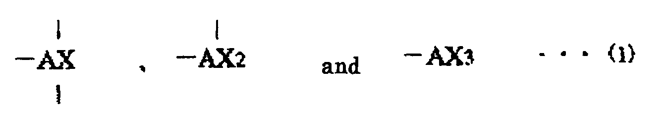
In addition, the functional group showing reactivity to the
functional group having active hydrogen can be one functional group
selected from the functional groups represented by the following general
formulas (1).
(In the formulas, A shows one kind of atom selected from a group
composed of silicon, germanium, tin, titanium and zirconium. X shows
one functional group selected from halogen, alkoxy group and isocyanate
group.)
Here, "on the base material" is not limited to the case where the molecules
are directly fixed to the surface of the base material, and includes a case
where the molecules are fixed via another substance layer.
(2) Organic Thin Film Manufacturing Method
-
In order to solve the above problems, an organic thin film
manufacturing method of the present invention is characterized by
comprising: the film forming step of bringing molecules having a
functional group showing reactivity to a functional group having active
hydrogen into contact with a base material so as to be bonded onto the
base material and forming a film composed of the molecules: and the
removing step of removing the molecules which are not bonded onto the
base material using a cleaning agent which contains at least one selected
from a group of ketone, alkylene glycol and alkoxy alcohol.
-
The molecules can have a functional group selected from the
functional groups represented by the following general formulas (1).
(In the equation, A shows one kind of atom selected from a group
composed of silicon, germanium, tin, titanium and zirconium. X shows
one kind of a functional group selected from halogen, alkoxy group and
isocyanate group.)
-
When the molecules having one functional group selected from the
functional groups represented by the above general formulas (1) are fixed
to the surface of the base material so that a film is formed at the film
forming step, the molecules which are not bonded to the base material
(unfixed molecules) remain on the surface of the film. The unfixed
molecules can be easily removed by using the cleaning agent which
contains at least one selected from a group of ketone, alkylene glycol and
alkoxy alcohol. This is because the ketone or the like has excellent
dissolving power with respect to unfixed molecules. As a result, at least
an organic thin film with uniform thickness composed of the molecules are
formed on the surface of the substrate so that an organic thin film with
uniform thickness can be manufactured.
-
As the ketone, at least one kind, of compound selected from a group
of acetone, methyl ethyl ketone, diethyl ketone, methyl isobutyl ketone
and acetylacetone can be used.
-
The group of these compounds have excellent dissolving power with
respect to molecules having one functional group selected from the
functional groups represented by the above general formulas (1).
Therefore, according to the above method using the group of compounds
with excellent cleaning power, suitable ketone is selected as the need
arises according to a type of the molecules and cleaning conditions so that
an organic thin film with uniform thickness where the unfixed molecules
are removed can be formed.
-
In addition, as the alkylene glycol, polyethylene glycol can be used.
-
The polyethylene glycol has excellent dissolving power with respect
to the compound having at least one functional group selected from the
functional groups represented by the above general formulas (1).
Therefore, according to the above method using polyethylene glycol with
excellent cleaning power, unfixed molecules can be removed more easily so
that an organic thin film from which the unfixed molecules are removed
can be formed.
-
Further, a molecular weight of the polyethylene glycol can be
within a range of not less than 100 to not more than 300.
-
As a result, since polyethylene glycol with low molecular weight is
used as the component of the cleaning agent, a cleaning agent with small
viscosity and excellent handing property can be obtained.
-
Further, as the cleaning agent, one which does not include a
chlorine-based solvent can be used.
-
As mentioned above, when the cleaning agent, which contains at
least one selected from a group of ketone, alkylene glycol and alkoxy
alcohol and does not include a chlorine-based solved, is used at the
removing step, a load to environment can be suppressed. Furthermore,
since this cleaning agent displays the cleaning effect equivalent to that of
a conventional cleaning agent composed of a chlorine-based solvent for an
object to be cleaned, namely, unfixed molecules, an organic thin film with
uniform thickness can be formed. Therefore, an organic thin film with
uniform thickness can be formed without using a chlorine-based solvent,
and an organic thin film manufacturing process in which a load to
environment is suppressed can be provided.
-
Further, after the removing step, the cleaning agent removing step
of removing the cleaning agent adhering to the base material can be
carried out.
-
As a result, the cleaning agent remains on the formed organic thin
film so that a bad influence can be prevented from being exerted on the
quality of the film. Particularly in the case where a functional film
having functions such as water-repellent effect and hydrophilic nature is
used, when the cleaning agent removing step is carried out, various
functional deteriorations can be prevented.
-
The cleaning agent removing step may include the rinse step of
rinsing off the cleaning agent adhering to the base material with water,
and the drying step of drying the water adhering to the base material.
-
This method can clean the cleaning agent adhering to the film
formed on the surface of the base material with water so as to remove it.
As a result, for example, in the case where the molecules have AX group, a
condensation reaction takes place between the AX group remaining on the
film and water, and hydroxyl group can be introduced into the molecules
composing the film. Moreover, when the base material is dried at the
drying step, water adhering to the base material can be removed. On the
other hand, when the drying step is carried out, dehydration reaction is
activated between the bonded molecules on the surface of the base
substrate so that a crosslinked structure can be obtained. Therefore, an
organic thin film having excellent abrasion resistance, resistance to
scratch and the like can be manufactured.
-
As the base material, a base material where a functional group
having active hydrogen exists on its surface can be used.
-
According to the above method, in the case where the molecules
have a functional group represented by the above general formulas (1), HX
molecules are eliminated so that condensation reaction can be caused. As
a result, the molecules having a functional group represented by the
general formulas (1) can be bonded to the surface of the base material.
-
Further, the film forming step and the removing step can be
carried out in dry atmosphere.
-
When the film forming step is carried out in dry atmosphere, a
monomolecular film if formed on the surface of the base material, and an
accumulated film where a plurality of monomolecular film-like molecular
layers are accumulated is formed on the monomolecular film. This is
because the moisture in atmosphere reacts to the functional group
represented by the above general formulas (1) and crosslinking is
prevented. Since the removing step is carried for the film formed in such
a manner in dry atmosphere, the whole accumulated film or some
molecular layers of the accumulated film can be removed easily. This is
because since the removing step is carried out also in dry atmosphere, the
condensation reaction due to elimination of HX molecules can be
prevented from taking place between the functional group represented by
the above general formulas (1) in the molecules forming the accumulated
film and the moisture in atmosphere. Therefore, the molecules which are
fixed to the surface of the base material or unfixed molecules are can be
prevented from crosslinking, and an organic thin film where a plurality of
monomolecular films or monomolecular film-like molecular layers are
accumulated can be formed.
-
The molecules having one functional group selected from the
functional groups represented by the above general formulas (1) are fixed
to become monomolecular film like so that an organic thin film can be
formed.
-
According to the above method, since a monomolecular film-shaped
organic thin film can be formed, a molecule design of the molecules having
the functional group represented by the above general formulas (1) is
controlled so that a film thickness can be easily controlled at molecule
level. As a result, a very thin organic thin film can be manufactured so
as to have a desired thickness.
(3) Organic Thin Film Manufacturing Apparatus
-
In order to solve the above problems, an organic thin film
manufacturing apparatus of the present invention, is characterized by
comprising: film forming means for bringing molecules having a functional
group showing reactivity to a functional group having active hydrogen into
contact with a base material so as to be bonded onto a surface of the base
material and forming a film composed of the molecules and removing
means for removing the molecules which are not bonded onto the base
material using a cleaning agent containing at least one selected from a
group of ketone, alkylene glycol and alkoxy alcohol.
-
The molecules have one functional group selected from the
functional groups represented by the following general formulas (1).
(In the equation, A shows one kind of atom selected from a group
composed of silicon, germanium, tin, titanium and zirconium. X shows
one functional group selected from halogen, alkoxy group and isocyanate
group.)
[Liquid Crystal Alignment Film, Manufaturing Method Thereof and
Manufacturing Apparatus Thereof]
(1) Liquid crystal Alignment film
-
In order to solve the above problems, a liquid crystal alignment
film of the present invention, which is composed of molecules bonded onto
a substrate and where liquid crystal molecules being aligned in a specified
direction, the is characterized in that the liquid crystal alignment film is
obtained so that after molecules having a functional group showing
reactivity to a functional group having active hydrogen are brought into
contact with a surface of the substrate to be bonded thereto, the molecules
which are not bonded to the substrate are removed by a cleaning agent
containing at least one selected from a group of ketone, alkylene glycol
and alkoxy alcohol.
-
The liquid crystal alignment film having the above structure is
composed of molecules which are arranged along the surface of the base
material in a state that one end of the thin film is bonded to the surface of
the base material and the other end is projected to a direction separating
from the surface of the base material. Since this alignment film is a thin
film which is cleaned by the above cleaning agent, unfixed molecules
which are not bonded to the substrate are removed so that an uniform
thickness can be obtained.
-
In addition, conventionally, when the substrate to which molecules
are fixed is cleaned by a cleaning agent (chlorine-based cleaning agent)
composed of a chlorine-based solvent, a film structure is occasionally such
that the molecules are fixed in a disordered state. On the contrary, since
the liquid crystal alignment film having the above structure is not a thin
film which is cleaned by the cleaning agent composed of a chlorine-based
solvent, a film structure that molecules are fixed to the substrate in
disordered state is prevented so that an organic thin film having an
ordered film structure where the molecules are arranged uniformly can be
provided.
-
Here, in the case where the liquid crystal alignment film having
the above structure is a monomolecular film, liquid crystal molecules in its
vicinity are inclined with respect to the substrate and/or restricted to an
alignment direction.
-
Therefore, as mentioned above, the ordered film structure that
individual molecules are aligned uniformly has excellent alignment
performance, and more concretely liquid crystal molecules can be aligned
without disordering the alignment state.
-
Here, "on the substrate" is not limited to the case where the
molecules are directly bonded to the surface of the substrate, and includes
the case where the molecules are bonded via another substance layer such
as an electrode.
-
In addition, the functional group showing reactivity a functional
group having active hydrogen can be one functional group selected from
the functional groups represented by the following general formulas (1).
(In the equation, A shows one kind of atom selected from a group
composed of silicon, germanium, tin, titanium and zirconium. X shows
one functional group selected from halogen, alkoxy group and isocyanate
group.)
(2) Liquid crystal alignment film manufacturing method
-
In order to solve the above problem, a liquid crystal alignment film
manufacturing method of the present invention is characterized by
comprising: film forming step of bringing molecules having a functional
group showing reactivity to a functional group having active hydrogen into
contact with a substrate to be bonded onto a surface of the substrate and
forming a film composed of the molecules and removing step of removing
the molecules which are not bonded to the substrate using a cleaning
agent containing at least one selected from a group of ketone, alkylene
glycol and alkoxy alcohol.
-
The molecules can have one functional group selected from the
functional groups represented by the following formulas (1).
(In the equation, A shows one kind of atom selected from a group
composed of silicon, germanium, tin, titanium and zirconium. X shows
one functional group selected from halogen, alkoxy group and isocyanate
group.)
-
When the molecules having one functional group selected from the
functional groups represented by the above general formulas (1) are fixed
to the surface of the substrate so that the film is formed at the film
forming step, unfixed molecules remains on the surface of the film. Since
ketone or the like displays excellent dissolving power with respect tot he
unfixed molecules, the unfixed molecules are cleaned by the above
cleaning agent so as to be capable of being removed easily. Therefore, at
least a liquid crystal alignment film composed of the molecules fixed onto
the substrate can be formed on the surface of the substrate while a load to
environment is being suppressed. Further, the liquid crystal alignment
film formed in the above method has a uniform thickness and a film
structure that the molecules are not disordered and are uniform.
(3) Liquid crystal alignment film manufacturing method
-
In order to solve the above problems, a liquid crystal alignment
film manufacturing apparatus of the present invention is characterized by
comprising: film forming means for bringing molecules having a functional
group showing reactivity to a functional group having active hydrogen into
contact with a substrate to be bonded to a surface of the substrate and
forming a film composed of the groups of molecule; and removing means
for removing the molecules which are not bonded to the substrate using a
cleaning agent containing at least one selected from a group of ketone,
alkylene glycol and alkoxy alcohol.
-
The molecules can have one functional group selected from the
functional groups represented by the following general formulas (1).
(In the equation, A shows one kind of atom selected from a group
composed of silicon, germanium, tin, titanium and zirconium. X shows
one functional group selected from halogen, alkoxy group and isocyanate
group.)
[Liquid Crystal Display Device and Manufacturing Method Thereof]
(1) Liquid crystal display device
-
In order to solve the above problems, a liquid crystal display device
of the present invention having a liquid crystal alignment film, in which
the liquid crystal alignment film is constituted so that liquid crystal
molecules are aligned on a substrate in a predetermined direction, is
characterized in that: the liquid crystal alignment film is a thin film
which is constituted so that molecules having a functional group showing
reactivity to a functional group having active hydrogen are bonded onto
the substrate, and after a group of the molecules are brought into contact
with to be bonded to the substrate, the molecules which are not bonded to
the substrate are removed by a cleaning agent containing at least one
selected from a group of ketone, alkylene glycol and alkoxy alcohol.
-
Since the liquid crystal alignment film of the liquid crystal display
device with the above structure is a thin film cleaned by the above
cleaning agent, the molecules which are not bonded to the substrate are
removed so that the thin film has a uniform thickness. Moreover, since
the liquid crystal alignment film is not a thin film cleaned by a
conventional cleaning agent composed of a chlorine-based solvent, it has
the ordered film structure that the molecules are aligned uniformly.
Therefore, liquid crystal molecules can be aligned without disorder of the
alignment state. Namely, due to the provision of the above-mentioned
liquid crystal alignment film, alignment defect or the like of the liquid
crystal is not visually recognized and display quality is excellent in the
liquid crystal display device having the above structure.
(2) Liquid crystal display apparatus manufacturing method
-
In order to solve the above problems, a liquid crystal display device
manufacturing method of the present invention, where the liquid crystal
display device has the liquid crystal alignment film which is constituted so
that liquid crystal molecules are aligned on a substrate in a
predetermined direction, is characterized by comprising film forming step
of bringing molecules having a functional group showing reactivity to a
functional group having active hydrogen into contact with the substrate to
be bonded onto a surface of the substrate and forming a film composed of
the molecules; and removing step of removing the molecules which are not
bonded to the substrate using a cleaning agent containing at least one
selected from a group of ketone, alkylene glycol and alkoxy alcohol.
-
According to the above method, a liquid crystal display device
having a liquid crystal alignment film with uniform thickness and
excellent alignment performance can be manufactured. Namely, when
the above cleaning agent is used as a substitute cleaning agent of a
chlorine-based cleaning agent, a liquid crystal display device with
excellent display quality can be manufactured while a load to environment
is being suppressed.
-
Another objects, features and advantages of the present invention
will be sufficiently understood by the following description. Moreover,
the advantages of the present invention are clarified by the following
description with reference to attached drawings.
BRIEF DESCRIPTION OF THE DRAWINGS
-
- Fig. 1 is a flow chart showing an organic thin film manufacturing
process according to an embodiment of the present invention.
- Fig. 2 is a flow chart for explaining a first cleaning agent removing
method according to a cleaning agent removing step in the organic thin
film manufacturing process.
- Fig. 3 is a flow chart for explaining a second cleaning agent
removing method according to the cleaning agent removing step in the
organic thin film manufacturing process.
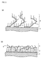
- Fig. 4 is an enlarged diagram of a main section schematically
showing a state that the organic thin film is adsorbed onto a base
material.
- Figs. 5 are cross sections schematically showing a state that the
organic thin film is adsorbed onto the base material: Fig. 5(a) is a diagram
showing a state that adsorbed molecules are adsorbed in a layer form; and
Fig. 5(b) is a diagram showing a state that the adsorbed molecules are
adsorbed onto the base material while being interlaced.
- Figs. 6 are enlarged diagrams of the main section schematically
showing a state that the organic thin film is adsorbed onto the base
material: Fig. 6(a) is a diagram showing a state that hydroxyl group is
introduced into the adsorbed molecules; and Fig. 6(b) is a diagram
showing a state that the adsorbed molecules crosslink.
- Figs. 7 are explanation diagrams schematically showing an organic
thin film manufacturing apparatus according to the present invention: Fig.
7(a) shows a case where film forming means and film removing means are
closed system; Fig. 7(b) shows a case where they are independent system;
and Fig. 7(c) schematically shows cleaning agent removing means.
- Figs. 8 are perspective views schematically showing removing
means according to the present invention: Fig. 8(a) shows a case of a batch
processing system; and Fig. 8(b) shows a case of a flow processing system.
- Fig. 9 is a cross section showing a liquid crystal display device
according to the present invention.
- Fig. 10 is an enlarged diagram of a main section schematically
showing a monomolecular film according to an embodiment 1-1 of the
present invention.
- Fig. 11 is a spectrum diagram of FT-IR of the monomolecular film
according to the embodiment 1-1.
- Fig. 12 is a spectrum diagram of FT-IR of a monomolecular film
according to a comparative example 1-1.
- Fig. 13 is an enlarged diagram of a main section schematically
showing a monomolecular film according to an embodiment 1-3 of the
present invention.
- Fig. 14 is a spectrum diagram of FT-IR of the monomolecular film
according to the embodiment 1-3.
- Fig. 15 is a spectrum diagram of FT-IR of the monomolecular film
according to a comparative example 1-2.
- Fig. 16 is a spectrum diagram of FT-IR of the monomolecular film
according to a comparative example 1-4.
- Fig. 17 is a spectrum diagram of FT-IR of the monomolecular film
according to a comparative example 1-5.
- Fig. 18 is an enlarged diagram of a main section schematically
showing the monomolecular film according to an embodiment 2-1 of the
present invention.
- Fig. 19 is a spectrum diagram of FT-IR of the monomolecular film
according to the embodiment 2-1.
- Fig. 20 is a spectrum diagram of FT-IR of the monomolecular film
according to a comparative example 2-1.
- Fig. 21 is an enlarged diagram of a main section schematically
showing the monomolecular film according to an embodiment 2-2 of the
present invention.
- Fig. 22 is a spectrum diagram of FT-IR of the monomolecular film
according to the embodiment 2-2.
- Fig. 23 is a spectrum diagram of FT-IR of the monomolecular film
according to a comparative example 2-2.
- Fig. 24 is a spectrum diagram of FT-IR of the monomolecular film
according to an embodiment 2-3 of the present invention.
- Fig. 25 is a spectrum diagram of FT-IR of the monomolecular film
according to a comparative example 2-3.
- Fig. 26 is a spectrum diagram of FT-IR of the monomolecular film
according to a comparative example 2-4.
-
BEST MODE FOR CARRYING OUT THE INVENTION
-
There will be explained below embodiments of the present
invention with reference to Figs. 1 through 8. Here, portions which
requires no explanation is omitted, and enlarged or reduced portions are
shown in the drawings in order to simplify the explanation. This is
applicable to the other drawings.
-
An organic thin film manufacturing method according to the
present invention is characterized by including: a film forming step of
bringing molecules having a functional group showing reactivity to a
functional group having active hydrogen into contact with a base material
to be fixed onto a surface of the base material and forming a film
composed of the molecules; and a removing step of removing the molecules
which are not fixed to the base material using a cleaning agent including
at least selected one kind of ketone, alkylene glycol and alkoxy alcohol.
-
Here, the molecules can be molecules having one functional group
selected from the functional groups represented by the following general
formulas (1).
(in the formulas, A shows one kind of atom selected from a group
composed of silicon, germanium, tin, titanium and zirconium. X shows
one functional group selected from halogen, alkoxy group and isocyanate
group.)
-
Further, examples of the halogen is F, Cl, Br and I, but Cl is
preferable from a viewpoint of reactivity to the base material.
-
The molecules having the functional group represented by the
above general formulas (1) are composed by bonding the following
functional groups to the functions group represented by the general
formulas (1).
- (a) hydrocarbon group such as methyl group, ethyl group, n-propyl
group, n-butyl group, n-pentyl group, n-hexyl group, n-heptyl group,
n-octyl group, n-nonyl group, n-decyl group, n-undecyl group, n-dodecyl
group, n-tridecyl group, n-tetradecyl group, n-pentadecyl group,
n-hexadecyl group, n-heptadecyl group, n-octadecyl group, n-nonadecyl
group, n-eicocyl group or phenyl group.
- (b) hydrocarbon group that a part of the hydrocarbon group
includes carbon-carbon double bond or carbon-carbon triple bond.
- (c) functional group that hydrogen in the hydrocarbon group in (a)
and (b) is substituted by another functional group (for example, methyl
group, halogenated methyl group, hydroxyl group, cyano group, amino
group, imino group, carboxyl group, ester group, thiol group, aldehyde
group or the like) and/or atom (for example, F, Cl, Br, I or the like).
- (d) functional group that a part of C-C bond in the hydrocarbon
group in (a) and (b) is substituted by C-O-C (ether) bond, C-CO-C
(carbonyl) bond or C = N bond.
Here, in the present invention, the functional group which is bonded to the
functional group represented by the general formulas (1) is not limited to
the above-mentioned ones.-
-
There will be detailed below an organic thin film manufacturing
method according to the present invention with reference to Fig. 1. At
first, an adsorption liquid that molecules having the functional group
represented by the general formulas (1) (hereinafter, occasionally referred
to as adsorption molecule or molecule) are dissolved in a nonaqueous
organic solvent is prepared (chemisorption solution preparing step, S1).
It is preferable that this chemisorption solution is prepared in a drying
atmosphere that a relative humidity is within a range of not more than
35%, for example, in dry air, dry nitrogen or dry helium.
-
Next, when the chemisorption solution prepared at the
chemisorption solution preparing step is brought into contact with a
base
material 1 degreased by previously cleaning it well (a film forming step,
S2), the molecules having the functional group represented by the general
formulas (1) are chemically adsorbed and fixed onto a surface of the base
material 1 (see Fig. 4). More specifically, condensation reaction takes
place between the molecules having the functional group represented by
the general formulas (1) and a functional group having active hydrogen
existing on the surface of the base material. For example, in the case
where the adsorbed molecules are molecules having -AX
3 group and the
functional group having active hydrogen is hydroxyl group, a reaction
represented by the following chemical equation (2) takes place.
(In the equation, A shows one kind of atom selected from a group
composed of silicon, germanium, tin, titanium and zirconium. X shows
one functional group selected from halogen, alkoxy group and isocyanate
group.)
-
As a result of the condensation reaction, molecules, where HX is
eliminated and which have the functional group represented by the
general formulas (1), are adsorbed onto the surface of the base material 1.
Here, the degreasing is executed in order to improve adherability of the
chemisorption solution to the surface of the base material 1, and surface
treatment may be conducted using a conventionally-known method.
-
Here, when the film forming step is carried out in an atmosphere of
normal humidity (namely, in the air), a thin film 3 shown in Fig. 5(a) is
formed on the surface of the base material 1. More specifically, adsorbed
molecules which are adsorbed onto the surface of the base material 1 are
bonded to non-adsorbed molecules which are not adsorbed onto the base
material 1, and another non-adsorbed molecules are bonded to the above
non-adsorbed molecules so that a chain is formed, and a polymer-like
structure is formed. This chain bends so as to extend upward (into air)
from the surface of the base material 1 and interlaces with another bent
chain three-dimensionally so that the thin film 3 is formed. The thin film
3 having such a film structure is formed because of the following reasons.
Namely, the non-adsorbed molecules which are not adsorbed onto the
surface of the base material 1 react to moisture in the atmosphere so that
HX molecules are eliminated. As a result, OH group is introduced into
the non-adsorbed molecules. The OH group reacts or the like to the
functional group (adsorbed portion) represented by the general formulas
(1) in another non-adsorbed molecules so as to crosslink. Therefore, the
thin film having the above structure is formed. Here, a thickness of the
thin film shown in the drawing is such that three monomolecular films
composed of adsorbed molecules are laminated, and in this case, this film
is referred to as three-molecular layer for the convenience. Meanwhile,
when the film forming step is carried out in a dry atmosphere (for example,
relative humidity is not more than 35%), as shown in Fig. 5(b), a
monomolecular film 2 is formed on the surface of the base material 1, and
non-adsorbed molecules 4 adhere to the surface of the monomolecular film
2 so that a thin film is formed. This is because the adsorbed portion in
the non-adsorbed molecules 4 does not react to moisture due to the dry
atmosphere and adhere to base material in a state that it has the
functional group represented by the general formulas (1).
-
The method of bringing the molecules having the functional group
represented by the general formulas (1) into contact with the surface of
the base material 1 is not particularly limited, and for example, a method
of soaking the base material 1 in an chemisorption solution previously
prepared, a method of applying the chemisorption solution to the base
material 1 or the like can be used.
-
In addition, as the functional group having active hydrogen
existing on the surface of the base material 1, in addition to the hydroxyl
group, for example, carboxyl group, sulfinic acid group, sulfonic acid group,
phosphoric acid group, phosphorous acid group, thiol group, amino group
and the like can be enumerated. Furthermore, a functional group that
the active hydrogen of the above functional group is substituted by alkali
metal or alkali earth metal may be used. Moreover, in the case where
the functional group having active hydrogen does not exist on the surface
of the base material 1 or few functional group exist, a compound oxidizing
agent treatment such as an UV/ozone treatment, an oxygen plasma
treatment or potassium permanganate solution is given. As a result, it is
preferable that the surface of the base material 1 is reformed and the
above functional group is introduced, or a number of the functional group
is increased.
-
Next, a removing step is carried out (S3) using a cleaning agent
containing at least one kind selected from a group of ketone, alkylene
glycol and alkoxy alcohol. A main object to be cleaned at this step is
groups of non-adsorbed molecules of the molecules having a functional
group represented by the general formulas (1) which is not fixed by
chemical linkage and remains on the surface of the base material 1.
More specifically, in Fig. 5(a), the object to be cleaned is not the base
material 1 but the non-adsorbed molecules which are bonded to adsorbed
molecules as constitutional molecules in a network-like molecular layer 3
formed on the base material 1. Moreover, in Fig. 15(b), the object to be
cleaned is an accumulated film 5 composed of the non-adsorbed molecules
4 adhering to the surface of the monomolecular film 2. The groups of
non-adsorbed molecules are dissolved in the cleaning agent so as to be
removed, and a monomolecular film-like organic thin film having uniform
thickness can be formed.
-
The ketone as cleaning component contained in the cleaning agent
has excellent solubility with respect to the molecules having a functional
group represented by the general formulas (1). Examples of the ketone
are acetone, methyl ethyl ketone, diethyl ketone, methyl isobutyl ketone
and acetylacetone.
-
In addition, examples of the alkylene glycol as cleaning component
contained in the cleaning agent are ethylene glycol group, propylene glycol
group and butylene glycol group. The ethylene glycol group is the most
preferable of all. The ethylene glycol group has less stench and no color,
and is characterized in that it easily blends with various organic solvents,
water, surface-active agents and the like. Therefore, the ethylene glycol
group is convenient to a design of the cleaning agents. More concretely,
the ethylene glycol group, for example, ethylene glycol monoethyl ether,
diethylene glycol monoethyl ether, diethylene glycol monoethyl ether
acetate, ethylene glycol monoethyl ether acetate, ethylene glycol
monomethyl ether, ethylene glycol monomethyl ether acetate, ethylene
glycol mono-n-butyl ether, ethylene glycol monophenyl ether and the like
can be used preferably.
-
Further, examples of the alkylene glycol may be polymers such as
polyethylene glycol group, polypropylene glycol group, polybutylene glycol
group. More specifically, as the polyethylene glycol group, for example,
polyethylene glycol, polyethylene glycol monoethyl ether, polydiethylene
glycol monoethyl ether, polydiethylene glycol monoethyl ether acetate,
polyethylene glycol monoethyl ether acetate, polyethylene glycol
monomethyl ether, polyethylene glycol monomethyl ether acetate,
polyethylene glycol mono-n-butyl ether polyethylene glycol monophenyl
ether and the like can be used suitable.
-
In the case where the alkylene glycol is polymer, it is preferable its
molecular weight is about not more than 2,000, more preferably it is
within a range of 100 to 300. In the case where the molecular weight is
larger than 2,000, viscosity becomes too large so that its handling
property is deteriorated. Here, in the case where polymer whose
molecular weight is about not less than 300, it is the most suitable for the
cleaning agent that the polymer is dissolved in water, alcohol or the like
and it is used as a solution. For example, in the case where polyethylene
glycol is used as polymer and it is dissolved in water, it is preferable
density of polyethylene glycol is about 10 to 50 wt%. Meanwhile, in the
case where polyethylene glycol is dissolved in alcohol, it is preferable that
the density is about 10 to 50 wt%.
-
On the other hand, the alkoxy alcohol is not particularly limited,
and concretely, its examples are methoxy alcohol and ethoxy ethanol.
-
The cleaning agent of the present invention may be a nonaqueous
cleaning agent in which one of ketone, alkylene glycol and alkoxy alcohol
is used solely. The removing step may be carried out in a dry atmosphere
(relative humidity: not more than 35%). For example, in the case where
the film where the accumulated film 5 is formed on the monomolecular
film 2 shown in Fig. 5(a) is cleaned, due to the dry atmosphere, it is
prevented that elimination reaction of HX molecule takes place between
moisture in the atmosphere and the functional group represented by the
general formulas (1) in the non-adsorbed molecules 4 and crosslinking
occurs. Therefore, the accumulated film 5 can be removed by the
detergent action of the cleaning agent so that a monomolecular film-like
organic thin film can be formed. Moreover, in the case where the
removing step is carried out in the dry atmosphere, a cleaning agent
having low moisture content is preferably used. More concretely, when
the moisture content is less than 1.0%, there arises no practical problem,
but about less than 0.1% is preferable, and about less than 0.01% is more
preferable. When the moisture content exceeds the above numerical
value range, since AX group in the non-adsorbed molecules and adsorbed
molecules reacts to water contained in the cleaning agent so that a
crosslinking structure is formed, a monomolecular film cannot be formed
also in this case.
-
Examples of the concrete cleaning method executed at the
removing step are a method of silently soaking the base material 1 in a
cleaning tank filled with the cleaning agent as well as a method of
applying a mechanical force to the base material 1 which is being soaked
in the cleaning agent such as emitting a ultrasonic wave thereto, and a
method of heating the cleaning agent in order to improve the cleaning
power of the cleaning agent. Here, in the case where a stress of the
ultrasonic wave or the like is applied to the base material 1, it is
necessary that the stress does not exert a bad influence on the base
material 1.
-
In addition, the cleaning conditions of the removing step are not
particularly limited, they may be set properly as the need arises
considering (a degree of adhesion of the non-adsorbed molecules to the
object to be cleaned), a material of the object to be cleaned, form of the
object to be cleaned and a bad influence on the thereafter steps. Further,
when concentration of the cleaning agent, cleaning time and a number of
cleaning times are changed, not only the monomolecular film-like organic
thin film but also an organic thin film having a thickness equivalent to
that of two molecular layers can be formed. Namely, a film thickness can
be controlled. That is, a remaining degree of the non-adsorbed molecules
is controlled so that the film thickness is controlled. For example, about
three cleaning tanks filled with the cleaning agent with predetermined
concentration are provided, and cleaning is executed in the respective
cleaning tanks for predetermined time so that a degree of the cleaning is
improved. As a result, most of the non-adsorbed molecules are removed,
and a monomolecular film-like organic thin film can be obtained. On the
other hand, in the case where about one cleaning tank is provided and the
cleaning is executed for shorter time than the predetermined time, namely,
light cleaning is executed, a lot of non-adsorbed molecules remain. When
the base material 1 is exposed to the air in such a state, the non-adsorbed
molecules react to moisture in the air to be fixed, and for example, an
organic thin film with a thickness equivalent to that of several molecular
layers such as two-molecular layer is formed.
-
Furthermore, in order to control the thickness of the organic thin
film formed into a monomolecular film form, a molecular design of
adsorbed molecules to be allowed to adhere to the base material 1 is
changed so that a thickness can be controlled accurately.
-
Next, after the removing step, a cleaning agent removing step of
removing a cleaning agent may be carried out (S4). This cleaning agent
removing step is mainly divided into a first cleaning agent removing
method of rinsing a cleaning agent using a rinse agent and a second
cleaning agent removing method of drying a cleaning agent to be
evaporated. The first cleaning agent removing method can be adopted to
the case where the cleaning agent contains at least one of ketone, alkylene
glycol and alkoxy alcohol. On the other hand, the second cleaning agent
removing method can be mainly adopted to the case where the cleaning
agent contains ketone.
-
The first cleaning agent removing method is composed of the rinse
step of rinsing the cleaning agent using a rinse agent (S5), and the rinse
agent drying step of evaporating the rinse agent to remove it (S6) (see Fig.
2). The first cleaning agent removing method is carried out preferably in
the case where molecules where AX group remains are adsorbed to the
surface of the base material 1, or in the case where a solvent having a
comparatively high boiling point is used as the cleaning agent from the
viewpoint of safety or the like. In the former case, the rinse step is
carried out in order that remaining cleaning agent is removed, and HX
eliminating reaction is allowed to take place so that OH group is
introduced into the adsorbed molecules (see Fig. 6(a)). Therefore, water
is preferably used as the rinse agent. Further, when the rinse agent
drying step (S6) is carried out, dehydration reaction takes place between
OH groups so that an organic thin film having a crosslinking structure
shown in Fig. 6(b) can be formed. Meanwhile, in the latter case, since a
high-boiling point solvent (cleaning agent) which adheres to an object to
be cleaned is hardly dried and evaporated at normal temperature, its main
object is to substitute the high-boiling point solvent by a low-boiling point
rinse agent. As the low-boiling point rinse agent to be used in this case,
acetone, alcohol or the like can be used. Here, in the rinse step, similarly
to the removing step, the rinsing effect can be improved by application of a
mechanical force such as a ultrasonic wave.
-
In addition, the second cleaning agent removing method includes a
cleaning agent drying step (S7) of evaporating a cleaning agent to be
evaporated (S7), and a contact step of bringing the base material 1 into
contact with moisture (S8), and a drying step of drying the moisture (S9)
(see Fig. 3). The second cleaning agent removing method is preferably
executed in the case where a low-boiling point cleaning agent such as
acetone and methyl ethyl ketone which is evaporated at normal
temperature is used. The contact step is executed in order to allowing AX
group remaining in the molecules adsorbed on the surface of the the base
material 1 react with moisture and introduce OH group into the adsorbed
molecules. Therefore, as the method of bringing the base material 1 into
contact with moisture, for example, a method of leaving the base material
1 in air and allowing the base material 1 to react with moisture in the air,
or a method of allowing the base material 1 to directly react with water is
adopted. Thereafter, the drying step (S9) is carried out, and dehydration
reaction takes place between OH groups so that an organic thin film
having a crosslinking structure can be formed.
-
Moreover, as for another method besides the above-mentioned
cleaning agent removing method, in the case where a low-boiling point
cleaning agent that AX group does not exist in the molecules adsorbed to
the base material 1 and which is evaporated at normal temperature is
used, the cleaning agent may be simply dried after the removing step.
-
Here, one kind of material selected from a group of glass, metal,
metal oxide, ceramics, plastic, timber, stone, fabric, paper, polymeric resin
and the like can be applied to the base material 1. Moreover, the surface
of the base material 1 is painted with coating compound. The base
materials made of the above materials have similar physical properties in
that a functional group having active hydrogen exists on their surfaces.
In the case where plastic is particularly used as the material of the base
material 1, it is considered that the property of the base material is
changed depending on a type of plastic or the base material 1 is damaged
due to dissolving or the like. Therefore, it is necessary to use a cleaning
agent after previously ensuring that the cleaning agent does not have the
above affects on the base material 1 made of plastic.
-
There will be listed concrete examples of applications to which the
present invention can be applied, but the present invention is not limited
to them.
- (a) Examples of edge tools: kitchen knife, scissors, knife, cutter, chisel,
razor, clipper, saw, plane, chisel, piercer, awl, cutting tools such as
turning tools, blade of drill, blade of blender, blade of juicer, blade of mill,
blade of lawn mower, punch, toll for cutting straw, staple of stapler, blade
of can opener, surgical knife and the like.
- (b) Examples of needle: needle of acupuncture, sewing needle, needle of
sewing machine, needle of futon, a needle of tatami mat, a needle of
injection, surgical needle, safety pin, push pin and the like.
- (c) Examples of ceramic: ceramic ware, glass ware, products made of
ceramic and enameling. For example, sanitary ware (for example, toilet
stool, washbowl, bathtub and the like), tableware (for example, rice bowl,
plate, bowl, teacup, can, bottle, container of percolator, pan, mortar, cut
and the like), flower vase (for example, basin, flowerpot, small vase and
the like), water tank (for example, water tank for culture, water tank
appreciation and the like), chemistry apparatus (for example, beaker,
reaction container, test tube, flask, petri dish, cooling tube, stirring rods,
stirrer, mortar, batt, syringe and the like), tile, enameled tableware,
enameled washbowl, enameled pan and the like).
- (d) Example of mirror: hand mirror, mirror of compact, full-length mirror,
mirror in bathroom, mirror in washroom, mirror of automobile (for
example, rear-view mirror, side-view mirror and the like), traffic mirror
(for example, mirror at curve, reflector and the like), half mirror, mirror
for shop window, mirror in department and the like.
- (e) Examples of molding components: press tool, foundry molding tool,
injection die, carrier tool, vacuum forming tool, blow mold, extrusion
molding die, inflation base, fabric spinneret, calendering roll and the like
- (f) Examples of garniture: clock, precious stone, pearl, sapphire, ruby,
emerald, garnet, cat's-eye, diamond, topaz, bloodstone, aquamarine,
sardonyx, turquoise, jade, marble, amethyst, cameo, opal, crystal, glass,
ring, bracelet, necklace, anklet, breastpin, tiepin, earring, pierced earring,
precious metal garniture, platinum, gold, silver, copper, aluminum,
titanium, tin, products made of alloy of them or stainless, glass frames
and the like.
- (g) Examples of food molding form: cake baking form, cookie baking form,
bread baking form, chocolate baking form, jelly molding form, ice cream
molding form, oven tray, ice tray and the like.
- (h) Examples of cookware: pan, iron pot, kettle, pot, bowl, frying pan, hot
plate, grill net, flinger, "takoyaki" plate, bread baking pot, pot of rice cake
maker, pot of rice cooker, ladle, whisk and the like.
- (i) Examples of paper: gravure paper, water repellent and oil repellent
paper, poster paper, high-grade booklet paper and the like.
- (j) Examples of resin: polypropylene, polyolefin such as polyethylene,
polyvinyl chloride, polyvinylidene chloride, polyamide, polyimide,
polyamide-imide, polyester, aramid, polystyrene, polysulfone,
polyether-sulfone, polyphenylene sulfide, phenol resin, furan resin, urea
resin, epoxy resin, polyurethane, silicone, ABS resin, methacrylic acid
resin, methacrylate resin, acrylic resin, acrylate resin, polyacetal resin,
polyphenylene oxide and the like.
- (k) Examples of electric home appliances: television, radio, tape recorder,
audio, personal computer, compact disk (CD), mini disk (MD), digital video
disk (DVD), refrigerator of freezing equipments, freezer, air conditioner,
juicer, blender, mill mixer, washing machine, vacuum cleaner, lighting
fixtures, tumbler drier, dishwasher, shaver, antenna, blade of electric fan,
dial plate, perm dryer and the like.
- (l) Examples of sporting goods: skis, snowboard, skateboard, fishing pole,
drop line, fishnet, float, pole for pole jump, ball, sailing board, jet-ski,
surfboard, golf ball, bowling ball and the like.
- (m) Example of applications to vehicle, vessel and airplane:
- (1) ABS resin: lamp cover, instrument panel, interior trim,
protector of motorcycle
- (2) cellulosic plastic: mark and steering wheel of automobile
- (3) FRP (fiber reinforced plastic): shell bumper, engine cover
- (4) phenol resin: brake
- (5) polyacetal: windshielded wiper gear, gas valve, caburetor parts
- (6) polyamide: radiator fan
- (7) polyacrylate: directional lens, dashboard lens, relay housing
- (8) polybutylene terephthalate: rear end, front fender
- (9) polyamino bis-maleimide: engine parts, gear box, wheel,
suspension
drive system
- (10) methacrylic resin: lamp cover lens, instrumental board,
instrumental board cover, center mark
- (11) polypropylene: bumper
- (12) polyphenylene oxide: radiator grill, wheel cap
- (13) polyurethane: bumper, fender, instrument panel fan,
- (14) unsaturated polyester resin: body, fuel tank, heater housing,
instrument board and the like.
- (n) Examples of office supplies: fountain pen, ball-point pen, mechanical
pencil, pen case, binder, desk, chair, bookshelf, rack, letter case, telephone
board, ruler, drawing utensil and the like.
- (o) Examples of building materials: roof material, outer wall material and
inner packing. ceramic tile, slate tile, galvanized sheet (galvanized sheet
iron) and the like as outer wall materials. timber (including processed
timber, mortar, concrete, ceramic-based sizing, metal-based sizing, brick,
stone, plastic materials, metallic material such as aluminum and the like.
timber (including processed timber), metallic material such as aluminum,
plastic materials, paper, fiber and the like as inner packing.
- (p) Examples of stone: granite, marble, granite and the like. For example,
building, building material, work of art, ornament, bath, gravestone,
monument, gatepost, stone fence, pitching and the like.
- (q) Examples of musical instrument and acoustic equipments: musical
instrument such as percussion instrument, string, calvier and aerophone,
acoustic equipments such as microphone and speaker. for example, drum,
cymbal, percussion, violin, cello, guitar, koto, piano, organ, accordion,
harmonica, flute, hakuhachi, horn and the like.
- (r) the others, thermos bottle, vacuum equipment, high withstand voltage
insulating glass and the like having high water and oil repellent
stainproof effect such as power transmitting glass or spark plug.
-
-
The inventors of the present invention have disclosed a
chemisorption film where film density is improved and a manufacturing
method thereof in Japanes Patent No. 2,598,867. In the chemically
adsorbed film manufacturing method disclosed in this publication,
adsorption reaction and cleaning for removing unreacted non-adsorbed
molecules are repeated alternatively so that a chemisorption agent is fixed
to a base body and a chemically adsorbed film, and a chemically adsorbed
film having high density is formed. Moreover, a nonaqueous solvent is
used for the cleaning, but the chemisorption film to be formed has a film
structure which is different form that of the organic thin film devised by
the inventors in the following points.
-
That is, the chemically adsorbed film formed by the above method,
since chemisorption graft molecules are bonded to chemisorption backbone
molecules first adsorbed to the base material even in a portion of the
surface of the base material where a functional group having active
hydrogen does not exist, a distance between molecules of the chemically
adsorbed film becomes short so that a structure with high density is
obtained. Furthermore, since hydroxyl group which is not used for
bonding to the chemisorption backbone molecules or the like are being
still bonded to the chemisorption graft molecules, a lot of hydroxyl group
remains in the chemisorption film.
-
Meanwhile, in the organic thin film of the present invention, since
most of the film forming molecules are adsorbed to the surface of the base
material, its density is lower than that of the chemisorption film.
Moreover, since the drying step is carried out in the manufacturing
process and dehydration reaction is allowed to take place between the
hydroxyl groups existing in the film so that the hydroxyl groups are
crosslinked, there is a low expectation that hydroxyl group exists in the
organic thin film in comparison with the chemisorption film.
-
Accordingly, the present invention establishes the manufacturing
process as for the organic thin film having the film structure essentially
different from that of the chemisorption film disclosed in the above
publication.
-
In addition, an organic thin film manufacturing apparatus of the
present invention is composed of film forming means and removing means
(see Fig. 7). Further, base material delivery means 52 composed of a
conventionally known carrier apparatus, for example, can be disposed
between the film forming means and the removing means.
-
The film forming means has a function that an chemisorption
solution is applied to a base material and groups of adsorbed molecules
included in the chemisorption solution are adsorbed and fixed onto the
base material so that a film is formed. As the film forming means,
concretely for example, a spinning or roller type coating applicator or the
like can be used.
-
The removing means has a function that an object to be cleaned is
cleaned by a cleaning agent including at least one selected from a group of
ketone, alkylene glycol and alkoxy alcohol. Here, the object to be cleaned
is non-adsorbed molecules which adhere to and remain on the base
material (unfixed molecules).
-
Further, the film forming means and the removing means may be
constituted so as to be included in one closed system, or they may be
disposed independently.
-
Like the above constitution, the film forming means and removing
means are in the one closed system so as to be capable of being isolated
from the external air. As a result, the film forming step and the
removing step can be carried out in a dry atmosphere (Fig. 7(a)). Here,
the constitution that the film forming means and the removing means are
in the one closed system means that, for example, air shielding means 51
in which the film forming means and removing means can be disposed is
included in the organic thin film manufacturing apparatus. The air
shielding means 51 is not particularly limited as long as it can isolate the
external air from the inside, and for example, a chamber, a processing
room or the like which can control temperature, humidity and the like can
be provided. As the air shielding means 51, convection control means,
which can, needless to say, control humidity as well as inner convection at
normal temperature and pressure, can be provided. As a result, inner
humidity and convection state can be controlled, and working safety can
be secured. The working safety is necessary because when a compound
with small molecular weight of ketone, alkylene glycol or alkoxy alcohol is
used, a cleaning agent containing them requires special care due to its
flammability.
-
In addition, the film forming means and the removing means, as
mentioned above, can be constituted as processing units which are
separated and independent from each other (Fig. 7(b)). Moreover, in the
case where the film forming step and the removing step are desired to be
carried out in a dry atmosphere, air shielding means may be disposed for
each processing unit so that those means can be isolated form the air and
can control humidity and the like.
-
The removing means may be of batch processing system or flow
processing system.
-
As the batch processing system, a soaking method or the like of
soaking a base material as an object to be cleaned can be used. As
concretely shown in Fig. 8(a), in this soaking method, the cleaning agent
32 is poured into a cleaning tank 31 and base materials 34 are placed in a
cassette 33, and the cassette 33 is soaked in the cleaning tank 31 for
predetermined time so that the base materials 34 are cleaned.
-
As shown in Fig. 8(b), for example, as the flow processing system, a
cleaning apparatus, which is composed of a carrier section 41 for carrying
the base materials 34 and a plurality of injection devices 42 for injecting a
cleaning agent, can be used. Further, the injection devices 42 are
composed of a gate arch-shaped main body section 43 and nozzles 43 for
injecting the cleaning agent like spray or droplet. Moreover, the nozzles
43 are provided so that the injection direction of the cleaning agent is the
same as a down direction. On the other hand, the carrier section 41 is
provided so as to be inside the gate arch-shaped main body section 43. In
the cleaning apparatus having the above structure, the base materials 34
placed on the carrier section 41 are carried to a direction of an arrow A,
and the cleaning agent is injected from the nozzles 44 so that the base
materials 34 are cleaned. The above-mentioned batch processing system
and the flow processing system are only examples, and the present
invention is not limited to the above means. Any techniques which have
the structure substantially same as the technical idea described in claims
of the present invention and the similar functions and effects are included
in the technical scope of the present invention.
-
In addition, the organic thin film manufacturing apparatus of the
present invention can be provided with cleaning agent removing means so
that the cleaning agent removing step of removing the cleaning agent
adhering to the base material is carried out as the need arises (Figs. 7(a)
and 7(b)). Further, the cleaning agent removing means, as shown in Fig.
7(c), may have rinse means and drying means. The rinse means is not
particularly limited, and conventionally known various rinse apparatuses
can be used. Moreover, the drying means is not particularly limited, and
conventionally known various drying apparatuses can be used. As the
drying means, blow by means of normal temperature wind or warm wind
can be suitably adopted.
-
In addition, in the case where a base material made of paper, fiber
or the like is used and an organic thin film is formed on this base material,
it is necessary to select a type of cleaning agents, a cleaning method and
the like suitably as the need arises.
[Liquid Crystal Alignment Film and Liquid Crystal Display Device]
-
In the case where the organic thin film of the present invention is
applied as the liquid crystal alignment film to a liquid crystal display
device, the organic thin film can be manufactured by the following
method.
-
At first, a substrate, on which electrodes or the like made of ITO
(indium tin oxide) are formed according to the above-mentioned procedure,
is brought into contact with the chemisorption solution so that the
adsorbed molecules are adsorbed (S2, see Fig. 1). The adsorbed
molecules can be adsorbed onto the surface of ITO because OH group
exists on the surface of ITO, and the adsorbed molecules has a functional
group showing reactivity to a functional group having active hydrogen
such as OH group. As a result, a thin film with excellent peeling
resistance can be formed.
-
In addition, in the case where little OH group or the like exist on
the surface of ITO, it is preferable that an excimer UV treatment, a
plasma treatment or the like is conducted, the surface of ITO is reformed
so that OH group is increased, or another substance layer (for example,
deposited SiO layer or the like) is formed on the substrate so that a liquid
crystal alignment film is formed via the substance layer.
-
Next, non-adsorption molecules remaining on the surface of the
substrate are cleaned and removed at S3. As a result, the remaining
non-adsorption molecules are removed so that a thin film with uniform
thickness can be formed. Therefore, turbulence of the alignment state of
liquid crystal due to the remaining non-adsorption molecules, namely, an
alignment defect can be suppressed. Moreover, in the case where
cleaning is carried out by a conventional cleaning agent such as
chloroform, there arose a problem that turbulence of the adsorbed state of
the adsorbed molecules occurs due to the cleaning. However, in the
above removing step, since the cleaning is carried out by using the
cleaning agent containing one selected from the group of ketone, alkylene
glycol and alkoxy alcohol, the turbulence of the adsorbed state of the
adsorbed molecules hardly occurs, and an ordered film structure that the
groups of adsorbed molecules align uniformly can be obtained.
-
Next, similarly to the case of the above-mentioned organic thin
film manufacturing method, the cleaning agent is removed or the like at
S4 so that the liquid crystal alignment film of the present invention can be
manufactured. Here, the liquid crystal alignment film may be subject to
an aligning treatment such as a rubbing treatment as the need arises.
-
As a result, the liquid crystal alignment film manufacturing
method of the present invention can form a liquid crystal alignment film
having uniform thickness without using a chlorine-based cleaning agent
while a load to environment is being suppressed.
-
The liquid crystal alignment film obtained in the above manner
can be applied to the liquid crystal display device according to the
embodiment shown in Fig. 9, for example. That is, the liquid crystal
display device of the present invention can be constituted so as to have a
first substrate 61, a second substrate 62 which twins with the first
substrate 61, and a liquid crystal layer 63 which intervenes between the
first substrate 61 and the second substrate 62. TFT (thin film transistor)
groups 64 and first electrodes 65 are formed on an inner side of the first
substrate 61, and a liquid crystal alignment film 66 is formed on the first
electrode 65. A color filter 67 is formed on an inner surface of the second
substrate 62, and a second electrode 68 is formed on the second substrate
62 and the color filter 67. A liquid crystal alignment film 69 is formed on
the second electrode 68. Moreover, the first substrate 61 and the second
substrate 62 are bonded by a seal member 70 so that liquid crystal is
sealed and held in a panel. A polarization plate 71 is provided on an
outer side of the first substrate 61, and a polarization plate 72 is provided
on an outer side of the second substrate 62.
-
The first substrate 61 and the second substrate 62 are transparent
substrates made of glass, for example. Moreover, the first electrode 65
and the second electrode 68 are transparent conductive film made of ITO,
for example. The liquid crystal layer 63 is constituted so as to include
nematic liquid crystal, for example. The color filter 67 is constituted so
as to include dots of R (red), G (green) and B (blue).
-
According to the liquid crystal display device having the above
structure, the alignment defect or the like of liquid crystal is not visually
recognized so that excellent display quality can be provided. This is
because, as mentioned above, the thickness of the liquid crystal alignment
film is uniform and the film structure that the groups of adsorbed
molecules are adsorbed uniformly is obtained, and thus excellent aligning
performance is displayed so that liquid crystal molecules can be aligned
without disorder of the alignment state.
-
Further, the liquid crystal display device having the above
structure can be manufactured by adopting a conventional known method
except that liquid crystal alignment films 66 and 69 are deposited by the
above-mentioned method.
-
The liquid crystal alignment film manufacturing apparatus
according to the present invention can have the structure similar to that
of the above-mentioned organic thin film manufacturing apparatus.
Therefore, the detailed explanation thereof is omitted.
-
There will be detailed exemplarily below suitable embodiments of
the present invention with reference to the drawings. Here, material,
manufacturing conditions and the like of the components described in the
embodiments are only explanatory examples, and the scope of the present
invention is not limited to them as long as particularly limited description
is not given.
[First Embodiment]
(Embodiment 1-1)
-
n-octadecyl trichlorosilane was dissolved in hexadecane so as to be
about 1 weight%, and an chemisorption solution A was prepared.
-
Next, a glass substrate 11 (2 cm × 5 cm, thickness: 1.1 mm)
which was subject to degreasing cleaning sufficiently was soaked in the
chemisorption solution A for 1 hour. As a result, a dehydrochlorination
reaction represented by the following chemical equation took place
between hydroxyl group existing on the surface of the glass substrate 11
and trichloroxyl group, and the chemisorption solution A was chemisorbed
onto the glass substrate 11 via siloxane bond.
-
Next, a sufficient amount (50 ml to 100 ml) of acetone as a cleaning
agent was poured into a cleaning tank in air of relative humidity of about
35% and was heated at about 45°C. The glass substrate 11 was
sufficiently cleaned in the cleaning tank. Further, the glass substrate 11
was rinsed sufficiently in order to rinse off polyethylene glycol which
adhered to the surface of the glass substrate 11 with water. As a result,
the cleaning agent is rinsed off, and unreacted Cl group in molecules
chemisorbed onto the glass substrate 11 is substituted by OH group.
Next, the glass substrate 11 was dried. As a result, a dehydration
reaction took place between the OH groups and the OH groups were
crosslinked so that a monomolecular film 12 shown in Fig. 10 was formed
on the glass substrate.
-
Here, when the monomolecular film 12 was measured by Fourier
transform infrared spectroscopy method (hereinafter, referred to as FT-IR),
as shown in Fig. 11, a signal, which is distinctive in 2930 to 2840 cm-1
(attribute: CH3 and -CH2-), 1470 cm-1 (attribute: -CH2-), and 1080 cm-1
(attribute: -Si-O-), could be obtained. As a result, it was confirmed that
the monomolecular film 12 shown in Fig. 10 was formed.
-
The removing step in the present embodiment may be carried out
in dry air with relative humidity of not more than 5% or in nitrogen, but
the satisfactory result could be obtained in air with relative humidity of
not more than 35%.
(Comparative example 1-1)
-
In this comparative example 1-1, the steps similar to the above
embodiment 1-1 except that chloroform was used as a cleaning agent were
carried out so that the monomolecular film 12 was deposited on the glass
substrate 11. When this monomolecular film 12 was subject to FT-IR
measurement, as shown in Fig. 12, a signal with absorption strength
approximately same as that of the absorption spectrum shown in Fig. 11
could be obtained in the absorption position approximately same as that of
the absorption pectrum shown in Fig. 11.
-
Furthermore, when the embodiment 1-1 was compared with the
comparative example 1-1 in detail, the following different points in the
film structures were found out. Namely, in the absorption spectrums
shown in Figs. 11 and 12, when adsorption to CH2 of 2920 cm-1 resulted
from asymmetric stretching vibration was compared with adsorption to
CH2 of 2860 cm-1 resulted from symmetric stretching vibration, its
absorption ratio became 2.2:1 in Fig. 11 of the embodiment 1-1 and 2.0:1
in Fig. 12 of the comparative example 1-1. This shows that the
monomolecular film of the embodiment 1-1 has the film structure which is
more uniform and ordered than that of the monomolecular film in the
comparative example 1-1. This is because in the FT-IR measurement
method, a judgment can be made that as the absorption ratio of CH2
reaches 1:1 closer, the adsorption state of the film forming molecules
(adsorbed molecules) is more disordered (T.Ohtake et al., Langmuir,
2081,8,1992).
(Embodiment 1-2)
-
In an embodiment 1-2, the steps similar to those in the
embodiment 1-1 except that methyl ethyl ketone (50 ml to 100 ml) was
used as a cleaning agent were carried out so that the monomolecular film
12 was disposed on the glass substrate 11. When this monomolecular
film 12 was subject to the FT-IR measurement, a signal with adsorption
strength approximately same as that in Fig. 11 was be obtained in the
position approximately same as that in Fig. 11.
(Embodiment 1-3)
-
At first, a compound of about 1 weight% represented by the
following chemical equation (4) was dissolved in siloxane-based solvent
(product name: KF96L made by Shin-Etsu Chemical Co. Ltd.)/toluene (=
10/1) so that an chemisorption solution B was prepared.
-
Next, the glass substrate 11 which was sufficiently degreased and
cleaned was soaked in the chemisorption solution B for 1 hour in a
nitrogen atmosphere. As a result, the molecules represented by the
above chemical equation (4) were chemisorbed onto the brass substrate 11
as represented by the following chemical equation (5).
-
Next, sufficient amount of acetone (50 ml to 100 ml) as a cleaning
agent was poured into a cleaning tank in air with humidity of 35%, and
the glass substrate 11 was sufficiently cleaned in the cleaning tank.
Further, the glass substrate 11 was sufficiently rinsed in order to rinse off
the acetone adhering to the surface of the glass substrate 11 with water.
As a result, the cleaning agent is rinsed off, and unreacted Cl group in the
molecules chemisorbed onto the glass substrate 11 is substituted by OH
group. Next, the glass substrate 11 was dried. As a result, the OH
groups are dehydrated to be crosslinked, and a monomolecular film 13
shown in Fig. 13 was formed on the glass substrate 11.
-
Here, when the monomolecular film 13 was measured by FT-IR, as
shown in Fig. 14, a signal, which is distinctive in 2920 to 2840 cm-1
(attribute: -CH2-), 1650 cm-1 (attribute: C=0), 1600 cm-1 (attribute: benzen
skeleton), 1345 cm-1 (attribute: benzen skeleton) and 1080 cm-1 (attribute:
-Si-O-), could be obtained. As a result, it was confirmed that the
monomolecular film 12 was formed.
(Comparative example 1-2)
-
In the comparative example 1-2, the steps similar to those in the
embodiment 1-3 except that chloroform was used as a cleaning agent were
carried out so that the monomolecular film 13 was deposited on the glass
substrate 11. When this monomolecular film 13 was subject to the FT-IR
measurement, as shown in Fig. 15, a signal with absorption strength
approximately same as that in Fig. 14 was obtained in a position
approximately same as that in Fig. 14.
-
Further, when the embodiment 1-3 was compared with the
comparative example 1-2 in detail, the following different points in the
film structures were found out. That is, in the absorption spectrums
shown in Figs. 14 and 15, absorption to CH2 of 2920 cm-1 resulted from
asymmetric stretching vibration was compared with absorption to CH2 of
2860 cm-1 resulted from symmetric stretching vibration, the absorption
ratio became 2.1:1 in Fig. 14 of the embodiment 1-3 and 1.9:1 in Fig. 15 of
the comparative example 1-2. Therefore, it was found that the
monomolecular film of the embodiment 1-3 has the film structure which is
more uniform and ordered than that of the monomolecular film of the
comparative example 1-2.
(Comparative example 1-3)
-
In the comparative example 1-3, the steps similar to those in the
embodiment 1-3 except that ethyl acetate or ethyl formate was used as a
cleaning agent were carried out so that the monomolecular film 13 was
deposited on the glass substrate 11. When the glass substrate 11 on
which the monomolecular film 13 was deposited was exposed to air, the
surface of the glass substrate 11 got a nebula in an instant so that a
transparent thin film could not be deposited. Here, the ethyl acetate, and
ethyl formate are ester group disclosed in Japanese Unexamined Patent
Application Publication Nos. 6-45142 (1994), 6-312477 (1994), 6-187692
(1994) and the like.
(Comparative example 1-4)
-
In the comparative example 1-4, the steps similar to those in the
embodiment 1-3 except that toluene was used as a cleaning agent were
carried out so that the monomolecular film 13 was deposited on the glass
substrate 11.
-
When the monomolecular film 13 deposited on the glass substrate
11 was observed, it was seen that the monomolecular film 13 clouded up
thin. Further, when the monomolecular film 13 was subject to the FT-IR
measurement, as shown in Fig. 16, a signal with great absorption strength
was obtained clearly differently from Figs. 14 and 15. This shows that in
the case where toluene is used as a cleaning agent, the cleaning is
insufficient.
(Comparative example 1-5)
-
In the comparative example 1-5, the steps similar to those in the
embodiment 1-3 except that DMF (dimethyl formamide) was used as a
cleaning agent were carried out so that the monomolecular film 13 was
deposited on the glass substrate 11.
-
When this monomolecular film was observed, it was seen as
colorless and transparent. Further, when the monomolecular film 13 was
subject to the FT-IR measurement, as shown in Fig. 17, a signal with
great absorption strength was obtained clearly differently from Figs. 14
and 15. This shows that in the case where DMF is used as a cleaning
agent, the cleaning is insufficient.
(Result)
-
According to the above results, it was confirmed that when an
organic thin film was manufactured, acetone or methyl ethyl ketone was
used as a cleaning agent at the removing step so that the cleaning effect
which is the same as that of chloroform was produced. Further, it was
confirmed that also in the case where diethyl ketone, methyl isobutyl
ketone, acetyl ketone or the like was used besides the acetone or methyl
ethyl ketone, the cleaning effect which is the same as that of the case
where chloroform was used can be produced. Meanwhile, it was
confirmed that the above cleaning agents have more excellent cleaning
effect in comparison with the case where toluene or DMF which is not a
chlorine-based cleaning agent was used as a cleaning agent. Therefore, it
was found that the cleaning agents according to the above embodiments
are useful as substitute cleaning agents of organic chlorine-based solvent.
[Second Embodiment]
(Embodiment 2-1)
-
At first, n-octadecyl trichlorosilane of about 1 weight% was
dissolved in hexadecane so that an chemisorption solution A was
prepared.
-
Next, a glass substrate 21 (20 × 7 mm, thickness: 1.1 mm) which
was subject to degreasing cleaning sufficiently was soaked in the
chemisorption solution A for 1 hour. As a result, dehydrochlorination
reaction represented by the following chemical equation took place
between hydroxyl group existing on the surface of the glass substrate 21
and trichloroxyl group so that the chemisorption solution A was
chemisorbed onto the glass substrate 21 via siloxane bond.
-
Next, polyethylene glycol (average molecular weight: 300) of 50 ml
(an amount that the glass substrate 21 is soaked therein sufficiently and
shaking-off cleaning is possible) as a cleaning agent was poured into a
cleaning tank in an air with relative humidity of about 35% to be heated
at about 45°C. The glass substrate 21 was cleaned in the cleaning tank
three times. Cleaning time required for the cleaning at a time was about
1 minute. Further, the glass substrate 21 was rinsed in order to rinse off
polyethylene glycol which adhered to the surface of the substrate 21 with
water. The rinsing was conducted by leaving the glass substrate 11 in
flowing water for 5 minutes. As a result, the cleaning agent is rinsed off,
and unreacted Cl group in the molecules chemisorbed to the glass
substrate 21 is substituted by OH group. Next, the glass substrate 21
was dried. As a result, the OH groups are dehydrated so as to be
crosslinked, and a monomolecular film 22 shown in Fig. 18 was formed on
the glass substrate 21.
-
Here, when the monomolecular film 22 was measured according to
the Fourier transform infrared spectroscopy method (hereinafter, referred
to as FT-IR), as shown in Fig. 19, a signal, which is distinctive in 2930 to
2840 cm-1 (attribute: CH3 and -CH2-), 1470 cm-1 (attribute: -CH2-), and
1080 cm-1 (attribute: -Si-O-), could be obtained. As a result, it was
confirmed that the monomolecular film 22 shown in Fig. 18 was formed.
-
The removing step in the present embodiment may be carried out
in dry air with relative humidity of not more than 5% or in nitrogen, but
the satisfactory result could be obtained in air with relative humidity of
not more than 35%.
(Comparative example 2-1)
-
In the comparative example 2-1, the steps similar to the above
embodiment 2-1 except that chloroform was used as a cleaning agent were
carried out so that the monomolecular film 22 was deposited on the glass
substrate 21. When this monomolecular film 22 was subject to FT-IR
measurement, as shown in Fig. 20, a signal with absorption strength
approximately same as that of the absorption spectrum shown in Fig. 20
could be obtained in the absorption position approximately same as that of
the absorption pectrum shown in Fig. 19.
-
Furthermore, when the embodiment 2-1 was compared with the
comparative example 2-1 in detail, the following different points in the
film structures were found out. Namely, in the absorption spectrums
shown in Figs. 19 and 20, when adsorption to CH2 of 2920 cm-1 resulted
from asymmetric stretching vibration was compared with adsorption to
CH2 of 2860 cm-1 resulted from symmetric stretching vibration, its
absorption ratio became 1.65:1 in Fig. 19 of the embodiment 2-1 and
1.58:1 in Fig. 20 of the comparative example 21. Therefore, it was found
that that the monomolecular film of the embodiment 2-1 has the film
structure which is more uniform and ordered than that of the
monomolecular film in the comparative example 2-1.
(Embodiment 2-2)
-
At first, a compound of about 1 weight% represented by the
following chemical equation (4) was dissolved in siloxane-based solvent
(product name: KF96L made by Shin-Etsu Chemical Co. Ltd..)/toluene (=
10/1) so that an chemisorption solution B was prepared.
-
Next, the glass substrate 21 which was sufficiently degreased and
cleaned was soaked in the chemisorption solution B for 1 hour in a
nitrogen atmosphere. As a result, the molecules represented by the
above chemical equation (4) were chemisorbed onto the brass substrate 21
as represented by the following chemical equation (5).
-
Next, sufficient amount of glycol ether (product name: PK-LCG55,
made by Parker Corporation) (average molecular weight: 200) as a
cleaning agent was poured into a cleaning tank in air with humidity of
50% so that the cleaning tank was heated at, about 80°C. The glass
substrate 21 was sufficiently cleaned in the cleaning tank. Further, the
glass substrate 21 was sufficiently rinsed in order to rinse off the
polyethylene glycol adhering to the surface of the glass substrate 21. As
a result, the cleaning agent is rinsed off, and unreacted Cl group in the
molecules chemisorbed onto the glass substrate is substituted by OH
group. Next, the glass substrate 21 was dried. As a result, the OH
groups are dehydrated to be crosslinked, and a monomolecular film 23
shown in Fig. 21 was formed on the glass substrate 21.
-
Here, when the monomolecular film 23 was measured by FT-IR, as
shown in Fig. 22, a signal, which is distinctive in 2920 to 2840 cm-1
(attribute: -CH2-), 1650 cm-1 (attribute: C=0), 1600 cm-1 (attribute: benzen
skeleton), 1345 cm-1 (attribute: benzen skeleton) and 1080 cm-1 (attribute:
-Si-O-), could be obtained. As a result, it was confirmed that the film was
formed.
(Comparative example 2-2)
-
In the comparative example 2-2, the steps similar to those in the
embodiment 2-2 except that chloroform was used as a cleaning agent were
carried out so that the monomolecular film 23 was deposited on the glass
substrate 21. When this monomolecular film 23 was subject to the FT-IR
measurement, as shown in Fig. 23, a signal with absorption strength
approximately same as that in Fig. 22 was obtained in a position
approximately same as that in Fig. 22.
-
Further, when the embodiment 2-2 was compared with the
comparative example 2-2 in detail, the following different points in the
film structures were found out. That is, in the absorption spectrums
shown in Figs. 22 and 23, absorption to CH2 of 2920 cm-1 resulted from
asymmetric stretching vibration was compared with absorption to CH2 of
2860 cm-1 resulted from symmetric stretching vibration, the absorption
ratio became 1.8:1 in Fig. 22 of the embodiment 2-2 and 1.7:1 in Fig. 23 of
the comparative example 2-2. Therefore, it was found that the
monomolecular film of the embodiment 2-2 has the film structure which is
more uniform and ordered than that of the monomolecular film of the
comparative example 2-2.
(Embodiment 2-3)
-
In the embodiment 2-3, the steps similar to those in the
embodiment 2-2 except that ethoxy ethanol was used as a cleaning agent
were carried out so that the monomolecular film 23 was deposited on the
glass substrate 21. When this monomolecular film 23 was subject to the
FT-IR measurement, as shown in Fig. 24, a signal with absorption
strength approximately same as that in Figs. 22 and 23 could be obtained
in a position approximately same as that in Figs. 22 and 23.
(Comparative example 2-3)
-
In the comparative example 2-3, the steps similar to those in the
embodiment 2-2 except that toluene was used as a cleaning agent were
carried out so that the monomolecular film 23 was deposited on the glass
substrate 21.
-
When the monomolecular film 23 deposited on the glass substrate
21 was observed, it was seen that the monomolecular film 23 clouded up
thin. Further, when the monomolecular film 23 was subject to the FT-IR
measurement, as shown in Fig. 25, a signal with great absorption strength
was obtained clearly differently from Figs. 22 and 23. This shows that in
the case where toluene is used as a cleaning agent, the cleaning is
insufficient.
(Comparative example 2-4)
-
In the comparative example 2-4, the steps similar to those in the
embodiment 2-2 except that DMF (dimethyl formamide) was used as a
cleaning agent were carried out so that the monomolecular film 23 was
deposited on the glass substrate 21.
-
When this monomolecular film 23 was observed, it was seen as
colorless and transparent. Further, when the monomolecular film 23 was
subject to the FT-IR measurement, as shown in Fig. 26, a signal with
great absorption strength was obtained clearly differently from Figs. 22
and 23. This shows that in the case where DMF is used as a cleaning
agent, the cleaning is insufficient.
(Result)
-
According to the above results, it was confirmed that when an
organic thin film was manufactured, polyethylene glycol, glycol ether or
ethoxy ethanol was used as a cleaning agent at the removing step so that
the cleaning effect which is the same as that of chloroform was produced.
As a result, the organic thin film with uniform thickness where
non-adsorbed molecules are removed could be manufactured. Meanwhile,
it was confirmed that the above cleaning agents have more excellent
cleaning effect in comparison with the case where toluene or DMF which
is not a chlorine-based cleaning agent was used as a cleaning agent.
Therefore, it was found that the cleaning agents according to the above
embodiments are useful as substitute cleaning agents of organic
chlorine-based solvent.
-
As this invention may be embodied in several forms without
departing from the spirits of essential characteristics thereof, the present
embodiment is therefore illustrative and not restrictive, since the scope of
the invention is defined by the appended claims rather than by the
description preceding them, and all changes that fall within metes and
bounds of the claims, or equivalence of such metes and bounds thereof are
therefore intended to be embraced by the claims.
INDUSTRIAL APPLICABILITY
-
As explained above, according to the structures of the present
invention, the problems of the present invention can be solved sufficiently.
-
That is, according to the organic thin film of the present invention,
since the organic thin film is formed by cleaned by the cleaning agent
containing at least one selected from the group of ketone, alkylene glycol
and alkoxy alcohol, the film structure with uniform thickness which is
aligned uniformly and is ordered can be obtained.
-
Further, according to the organic thin film manufacturing method
of the present invention, the cleaning agent which contains at least one
selected from the group of ketone, alkylene glycol and alkoxy alcohol is
used so that unfixed molecules can be removed by using this cleaning
agent as substitute cleaning agent of a chlorine-based solvent. As a
result, the organic thin film having uniform thickness can be
manufactured. As a result, the organic thin film manufacturing process
which reduces a load to environment can be provided.
-
In addition, according to the liquid crystal alignment film of the
present invention, since this alignment film has the film structure where
the thickness is uniform and molecules are aligned uniformed and ordered,
liquid crystal molecules can be aligned without disturbing the alignment
state.
-
Further, according to the liquid crystal alignment film
manufacturing method of the present invention, the cleaning agent which
contains at least one selected from the group of ketone, alkylene glycol
and alkoxy alcohol is used so that unfixed molecules can be removed
without using a chlorine-based organic solvent, and the liquid crystal
alignment film with uniform thickness can be manufactured. Moreover,
the liquid crystal alignment film, which has the adsorption state with
respect to a substrate and excellent alignment function, can be
manufactured while a load to environment is being reduced without
disordering the film structure.
-
Further, the liquid crystal display device having such a liquid
crystal alignment film can produce the effect that alignment defect or the
like of liquid crystal is not visually recognized and display quality is
excellent. Therefore, the industrial significance of the present invention
is great.