EP1085624A1 - Method and device for optical power stabilisation of a laser emitter - Google Patents
Method and device for optical power stabilisation of a laser emitter Download PDFInfo
- Publication number
- EP1085624A1 EP1085624A1 EP00402512A EP00402512A EP1085624A1 EP 1085624 A1 EP1085624 A1 EP 1085624A1 EP 00402512 A EP00402512 A EP 00402512A EP 00402512 A EP00402512 A EP 00402512A EP 1085624 A1 EP1085624 A1 EP 1085624A1
- Authority
- EP
- European Patent Office
- Prior art keywords
- temperature
- current
- diode
- function
- laser diode
- Prior art date
- Legal status (The legal status is an assumption and is not a legal conclusion. Google has not performed a legal analysis and makes no representation as to the accuracy of the status listed.)
- Withdrawn
Links
Images


Classifications
-
- H—ELECTRICITY
- H01—ELECTRIC ELEMENTS
- H01S—DEVICES USING THE PROCESS OF LIGHT AMPLIFICATION BY STIMULATED EMISSION OF RADIATION [LASER] TO AMPLIFY OR GENERATE LIGHT; DEVICES USING STIMULATED EMISSION OF ELECTROMAGNETIC RADIATION IN WAVE RANGES OTHER THAN OPTICAL
- H01S5/00—Semiconductor lasers
- H01S5/06—Arrangements for controlling the laser output parameters, e.g. by operating on the active medium
- H01S5/068—Stabilisation of laser output parameters
- H01S5/06804—Stabilisation of laser output parameters by monitoring an external parameter, e.g. temperature
-
- H—ELECTRICITY
- H01—ELECTRIC ELEMENTS
- H01S—DEVICES USING THE PROCESS OF LIGHT AMPLIFICATION BY STIMULATED EMISSION OF RADIATION [LASER] TO AMPLIFY OR GENERATE LIGHT; DEVICES USING STIMULATED EMISSION OF ELECTROMAGNETIC RADIATION IN WAVE RANGES OTHER THAN OPTICAL
- H01S5/00—Semiconductor lasers
- H01S5/06—Arrangements for controlling the laser output parameters, e.g. by operating on the active medium
- H01S5/0617—Arrangements for controlling the laser output parameters, e.g. by operating on the active medium using memorised or pre-programmed laser characteristics
-
- H—ELECTRICITY
- H01—ELECTRIC ELEMENTS
- H01S—DEVICES USING THE PROCESS OF LIGHT AMPLIFICATION BY STIMULATED EMISSION OF RADIATION [LASER] TO AMPLIFY OR GENERATE LIGHT; DEVICES USING STIMULATED EMISSION OF ELECTROMAGNETIC RADIATION IN WAVE RANGES OTHER THAN OPTICAL
- H01S5/00—Semiconductor lasers
- H01S5/06—Arrangements for controlling the laser output parameters, e.g. by operating on the active medium
- H01S5/068—Stabilisation of laser output parameters
- H01S5/06812—Stabilisation of laser output parameters by monitoring or fixing the threshold current or other specific points of the L-I or V-I characteristics
Definitions
- the present invention relates to power control optics of a laser transmitter of the type comprising a laser diode and current means for supplying a control current to the laser diode composed of a bias current and a modulation current.
- the invention applies in particular to laser transmitters of the type VCSEL abbreviation for Vertical Cavity Surface Emitting Laser.
- diodes whose variation in optical power or threshold current as a function of temperature can be represented by a second order mathematical relation or more.
- the object of the invention relates to a power control method optics and a suitable device implementing an approximation second order math or more of the change in threshold current or of the power of the diode as a function of the temperature and to a correction of the control current as a function of the result of this approximation.
- the threshold current I s is defined as being the minimum current necessary to obtain the stimulated emission from the diode.
- the invention relates to a power control method.
- optics of a laser transmitter of the type comprising a laser diode and current means for supplying control currents to the laser diode made of a bias current and a modulation current.
- bias current I p and / or the value of the modulation current I m are determined for example from a measurement of the temperature or of a measurement of the voltage V across the terminals of the laser diode and of a relation between the variation of the voltage V and the temperature T.
- the invention also relates to a device for controlling the temperature of a laser diode of the type comprising a laser diode, a bias current generator (S p ) and / or a modulation current generator (S m ).
- the device capable of determining the parameter representative of the variation of the threshold current I s or of the optical power P of the diode as a function of the temperature T of the diode is a device for measuring the temperature or a device for measuring the voltage across the diode and a device adapted to establish and / or memorize a relationship between the variation of the voltage as a function of the temperature.
- the device and the method according to the invention apply for control the optical power of a VCSEL type diode or any diode for which the variation of the threshold current as a function of the temperature can be represented by a second order mathematical relation or more.
- FIG. 1 represents, for two different temperatures, the variations in the optical power P delivered by a laser diode of the VCSEL type as a function of the current I which flows in the diode.
- Curve C o corresponds to the optimal temperature, T o , for operating the laser and has a substantially straight portion of slope G o and curve C a shifted to the right (in the direction of increasing values of the current) is obtained for a any temperature T a , and has a substantially straight portion of slope G a lower than the slope G o .
- the optimal temperature corresponds to the maximum of the curve P (T) and at the minimum of curve I (T) ( Figure 2).
- the threshold current I s varies from the value I o to the value la when the temperature goes from T o to T a .
- the value of the optical power P m indicated in FIG. 1 corresponds substantially to the optical power obtained with the threshold current I threshold whatever the value of the temperature.
- the modulation current I m of the diode can be modified in order to take account of the modification of the slope G a of the rectilinear part of the curves C a .
- FIG. 2 shows a curve (I) obtained for Honeywell VCSEL diodes reference HFX6999, and representing the variation of the threshold current I s as a function of the temperature T for an optical power P m of 1 ⁇ W.
- This curve is an average curve and the deviations from this average curve, whatever the diode considered, are always very small.
- This variation curve is almost parabolic in the range of temperatures considered, in this example of application between -30 and + 80 ° C.
- I s (T) a T 2 + bT + c and, by choosing the coefficients a, b and c appropriately, the curve recorded by measurements and its parabolic approximation are almost confused.
- the coefficients a, b and c are for example determined from three points on the curve I s (T), in this example for the coordinate points: I s 8.4 mA 5,7mA 4mA T -30 ° 0 ° 70 °
- the coefficients a, b and c are for example obtained during tests prerequisites, for a given diode and constitute a database integrated for example in a computing device, as described in the figure 3.
- the coefficients can also be determined during operation by a digital device known to those skilled in the art.
- the curve (II) of figure 2 represents the variation of the power optical P as a function of temperature.
- the curve (I) of FIG. 2 relates to the variation of the current of threshold as a function of temperature.
- FIG. 3 shows a first example of an electrical diagram of a laser diode transmitter L comprising a control device for adjusting the bias current I p and the modulation current I m of the laser diode as a function of the temperature.
- the device comprises for example two transistors of the npn type, T r1 , T r2 , associated in a differential structure with a modulation signal V m applied between their respective bases.
- the collector of T r1 is connected to a positive direct voltage, Vc, by a resistor R.
- the collector of Tr2 is connected on the one hand to the cathode of diode L and on the other hand to ground by a current generator , S p .
- the anode of the diode L is connected to the voltage Vc.
- the emitters of the transistors T r1 and T r2 are connected to ground by the same current generator S m .
- the generators S p and S m are for example variable generators whose current produced is proportional to the amplitude of their control signal.
- the current generator S p supplies a bias current I p of the laser diode L.
- This current is composed of a fixed part le to which is added an adjustable part.
- the fixed part corresponds for example to the nominal threshold current, that is to say to a nominal operating point in power of the diode which has been fixed beforehand.
- the current generator S m supplies the modulation current I m of the diode L with, also, a fixed part I d and an adjustable part.
- the temperature control means include for example a circuit 1 for measuring the temperature of diode L, connected to a circuit calculation 2, itself followed by an adjustable gain amplifier 3.
- Circuit 1 for temperature measurement including an exemplary embodiment is given in figure 4 provides a voltage proportional to the temperature T which is transmitted to the calculation circuit 2.
- the voltage being proportional to the temperature T, it is assimilated to the latter and noted T.
- the circuit 1 comprises a differential amplifier A t whose positive input ⁇ is grounded and whose negative input - is connected on the one hand to a reference potential V ref through a resistance R t and on the other hand to the anode of a diode D t whose cathode is connected to the output of the amplifier A t .
- the diodes D t and L are, for example, part of the same array of diodes and are produced according to the same manufacturing process, which in particular makes it possible to optimize the temperature measurement.
- the current generator S p supplies a current proportional to V s , increased by the constant part le.
- FIG. 5 describes an exemplary embodiment of the calculation circuit 2.
- the circuit comprises an analog multiplier, M, comprising two inputs E 1 and E 2 connected to a first operational amplifier A 1 itself connected to a second amplifier A2.
- the temperature T supplied in the form of a voltage, is applied to the two inputs E 1 and E 2 of the multiplier M and to a first terminal of a resistor R 2 .
- the second terminal of R 2 is connected on the one hand to the positive input ⁇ of the amplifier A 1 and on the other hand to ground through a resistor R 3 .
- the output S of the multiplier is connected to the negative input - of the amplifier A 1 by a resistor R 1 , a resistor R 4 connects between them the negative input - and its output of the amplifier A 1 .
- the output of amplifier A 1 is connected by a resistor R 5 to the negative input - of amplifier A 2 .
- the positive input ⁇ of A 2 is connected to the cursor of a potentiometer R 6 whose ends are respectively at potentials Vd and Ve for example -5 volts and +5 volts.
- a resistor R 7 of substantially identical value as the resistor R 5 interconnects the negative input - and the output of the amplifier A 2 .
- the gain of the gain adjustment amplifier 3 (figure 3) is set to G value i.e. on the previously mentioned multiplicative coefficient for the curves P function of I.
- the adjustable gain amplifier 3 is replaced, for example, by a memory circuit 3 ′ shown in broken lines in FIG. 3.
- bias currents I p and modulation currents I m are calculated as mentioned above.
- FIG. 6 represents two curves of variation of the optical power P as a function of the temperature of the laser diode.
- the available power drops rapidly on either side of a temperature which, in the example described, is of the order of 40 ° C., with temperature control it remains almost stable, equal to the maximum optical power obtained without temperature control.
- the method includes a step of measuring the voltage across the diode L.
- the principle consists in determining the evolution of the threshold current of the VCSEL diode from the power / current characteristics recorded at different temperatures (curve II of FIG. 2).
- This curve III can be assimilated to a straight line D which retains the same slope or substantially the same slope whatever the value of the current I in a wide temperature range.
- the intercept of the line varies with the current and can be taken into account in the servo device.
- the VCSEL diode Under normal operating conditions, at ambient temperature and at nominal current, the VCSEL diode delivers a normal power P under a normal voltage V which corresponds to a threshold current value I snormale .
- the difference (Is-Is Normal ) is fed back into the supply circuit of the VCSEL diode so as to reset the diode to the P Normal power level.
- Normal power and normal threshold current are two values set by the user.
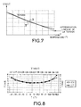
- Figure 7 shows a variation curve of the voltage V expressed in Volt as a function of the temperature T given in ° Celsius.
- T V - b 1 at 1
- V s AV 2 + BV + VS
- a 1 and b 1 are determined during preliminary tests for several referenced diodes or else be obtained during operation. They are deduced by conventional methods from two points on the line.
- the measured curve I s (T) is well approximated by the curve I s (V) calculated from the mathematical approximation.
- the current Ip and current Im values are determined as described above.
- Figure 9 shows schematically an example of a circuit where the elements identical to Figure 3 bear the same references.
- Calculation circuit 2 is adapted to calculate the value of the voltage across the VCSEL diode. For this it is connected to the point Vc which corresponds for example to the supply voltage of the circuit and to a point Vd located near the cathode of the diode by known connections of the skilled person.
- this method can be applied for the control of the modulation current I m .
- control device can be produced in the form digital, in particular with regard to the calculation circuit 2 of the figure 3.
Abstract
Description
La présente invention concerne le contrôle de la puissance optique d'un émetteur laser du type comportant une diode laser et des moyens en courant pour fournir à la diode laser un courant de commande composé d'un courant de polarisation et d'un courant de modulation.The present invention relates to power control optics of a laser transmitter of the type comprising a laser diode and current means for supplying a control current to the laser diode composed of a bias current and a modulation current.
L'invention s'applique en particulier aux émetteurs lasers de type VCSEL abréviation anglo-saxonne de Vertical Cavity Surface Emitting Laser.The invention applies in particular to laser transmitters of the type VCSEL abbreviation for Vertical Cavity Surface Emitting Laser.
Elle peut aussi être utilisée pour des diodes dont la variation de la puissance optique ou du courant de seuil en fonction de la température peut être représentée par une relation mathématique du second ordre ou plus.It can also be used for diodes whose variation in optical power or threshold current as a function of temperature can be represented by a second order mathematical relation or more.
Pour contrebalancer les effets de la température sur la puissance optique délivrée par un émetteur laser, il est connu de réaliser un contrôle de cette puissance d'émission au moyen d'une photodiode de contre-réaction. La photodiode mesure la puissance optique délivrée et, en fonction du résultat de cette mesure, les courants de polarisation et/ou de modulation de la diode laser sont réglés afin que la puissance optique émise reste sensiblement constante.To offset the effects of temperature on power optics delivered by a laser transmitter, it is known to carry out a control of this transmission power by means of a feedback photodiode. The photodiode measures the optical power delivered and, depending on the result of this measurement, the polarization and / or modulation currents of the laser diode are adjusted so that the transmitted optical power remains substantially constant.
Cette façon de procéder présente toutefois deux inconvénients :
- la partie de la puissance optique prélevée pour effectuer la mesure diminue le rendement optique global de l'émetteur,
- la nécessité d'un couplage optique de la photodiode à la diode laser au moyen par exemple d'un miroir semi-réfléchissant. Un tel agencement augmente fortement le coût de l'émetteur laser en raison des constituants mis en oeuvre et de l'obligation de les positionner de manière très précise par rapport à la diode laser.
- the part of the optical power taken to carry out the measurement reduces the overall optical efficiency of the transmitter,
- the need for an optical coupling of the photodiode to the laser diode by means for example of a semi-reflecting mirror. Such an arrangement greatly increases the cost of the laser transmitter because of the constituents used and the obligation to position them very precisely with respect to the laser diode.
L'objet de l'invention concerne un procédé de contrôle en puissance optique et un dispositif adapté mettant en oeuvre une approximation mathématique du second ordre ou plus de la variation du courant de seuil ou de la puissance de la diode en fonction de la température et à une correction du courant de commande en fonction du résultat de cette approximation.The object of the invention relates to a power control method optics and a suitable device implementing an approximation second order math or more of the change in threshold current or of the power of the diode as a function of the temperature and to a correction of the control current as a function of the result of this approximation.
Le courant de seuil Is est défini comme étant le courant minimal nécessaire pour obtenir l'émission stimulée de la diode. The threshold current I s is defined as being the minimum current necessary to obtain the stimulated emission from the diode.
L'invention concerne un procédé de contrôle de la puissance optique d'un émetteur laser du type comportant une diode laser et des moyens en courant pour fournir à la diode laser des courants de commande faits d'un courant de polarisation et d'un courant de modulation.The invention relates to a power control method. optics of a laser transmitter of the type comprising a laser diode and current means for supplying control currents to the laser diode made of a bias current and a modulation current.
Il est caractérisé en ce qu'il comporte au moins les étapes suivantes :
- établir une relation ou approximation mathématique du second ordre ou plus représentative des variations du courant de seuil ou de la variation de puissance de la diode laser en fonction de la température, et
- faire varier le courant de polarisation Ip et/ou le courant de modulation Im en fonction de la valeur issue de l'approximation.
- establish a mathematical relation or approximation of the second order or more representative of the variations of the threshold current or of the variation of power of the laser diode as a function of the temperature, and
- varying the bias current I p and / or the modulation current I m as a function of the value obtained from the approximation.
La valeur de courant de polarisation Ip et/ou la valeur du courant de modulation Im sont déterminées par exemple à partir d'une mesure de la température ou d'une mesure de la tension V aux bornes de la diode laser et d'une relation entre la variation de la tension V et la température T.The value of bias current I p and / or the value of the modulation current I m are determined for example from a measurement of the temperature or of a measurement of the voltage V across the terminals of the laser diode and of a relation between the variation of the voltage V and the temperature T.
L'invention concerne aussi un dispositif de contrôle en température d'une diode laser du type comportant une diode laser, un générateur de courant de polarisation (Sp) et/ou un générateur de courant de modulation (Sm).The invention also relates to a device for controlling the temperature of a laser diode of the type comprising a laser diode, a bias current generator (S p ) and / or a modulation current generator (S m ).
Il est caractérisé en ce qu'il comporte au moins :
- un dispositif permettant d'établir et/ou de mémoriser au moins une relation mathématique de second ordre ou plus entre la variation du courant de seuil Is de la diode laser et la température T et de déterminer une valeur de courant,
- un dispositif capable de déterminer au moins un paramètre représentatif de la variation du courant de seuil Is ou de la puissance optique P de la diode en fonction de la température T de la diode,
- un dispositif de commande et de contrôle adapté à générer un signal de commande pour faire varier le courant de polarisation Ip et/ou le courant de modulation Im en fonction du résultat issu du dispositif d'approximation.
- a device making it possible to establish and / or memorize at least one second or more second order mathematical relationship between the variation of the threshold current I s of the laser diode and the temperature T and to determine a current value,
- a device capable of determining at least one parameter representative of the variation of the threshold current I s or of the optical power P of the diode as a function of the temperature T of the diode,
- a command and control device adapted to generate a command signal for varying the bias current I p and / or the modulation current I m according to the result from the approximation device.
Le dispositif capable de déterminer le paramètre représentatif de la variation du courant de seuil Is ou de la puissance optique P de la diode en fonction de la température T de la diode est un dispositif de mesure de la température ou un dispositif de mesure de la tension aux bornes de la diode et un dispositif adapté à établir et/ou à mémoriser une relation entre la variation de la tension en fonction de la température. The device capable of determining the parameter representative of the variation of the threshold current I s or of the optical power P of the diode as a function of the temperature T of the diode is a device for measuring the temperature or a device for measuring the voltage across the diode and a device adapted to establish and / or memorize a relationship between the variation of the voltage as a function of the temperature.
Le dispositif et le procédé selon l'invention s'applique pour contrôler la puissance optique d'une diode de type VCSEL ou de toute diode pour laquelle la variation du courant de seuil en fonction de la température peut être représentée par une relation mathématique du second ordre ou plus.The device and the method according to the invention apply for control the optical power of a VCSEL type diode or any diode for which the variation of the threshold current as a function of the temperature can be represented by a second order mathematical relation or more.
La présente invention sera mieux comprise et d'autres caractéristiques apparaítront à l'aide de la description ci-après et des figures s'y rapportant où :
- la figure 1 représentent deux courbes de puissance optique délivrée par un laser de type VCSEL en fonction du courant circulant dans le laser, relativement à deux températures de fonctionnement du laser,
- la figure 2 montre la courbe de variation du courant de seuil Is et la courbe de variation de la puissance en fonction de la température de fonctionnement pour un laser de type VCSEL,
- la figure 3 est un schéma d'un laser contrôlé selon l'invention,
- les figures 4 et 5 correspondent à des schémas plus détaillés de certains éléments de la figure 3,
- la figure 6 représente deux courbes de variation de la puissance optique d'un laser en fonction de sa température de fonctionnement,
- la figure 7 montre la courbe de variation de la tension prise aux bornes de la diode en fonction de la température,
- La figure 8 deux courbes de variation du courant de seuil mesuré et calculé, et
- la figure 9 un schéma d'un dispositif de contrôle et de commande du laser.
- FIG. 1 represent two optical power curves delivered by a VCSEL type laser as a function of the current flowing in the laser, relatively to two operating temperatures of the laser,
- FIG. 2 shows the curve of variation of the threshold current I s and the curve of variation of the power as a function of the operating temperature for a laser of the VCSEL type,
- FIG. 3 is a diagram of a controlled laser according to the invention,
- FIGS. 4 and 5 correspond to more detailed diagrams of certain elements of FIG. 3,
- FIG. 6 represents two curves of variation of the optical power of a laser as a function of its operating temperature,
- FIG. 7 shows the curve of variation of the voltage taken across the terminals of the diode as a function of the temperature,
- FIG. 8 two variation curves of the measured and calculated threshold current, and
- FIG. 9 is a diagram of a device for monitoring and controlling the laser.
Sur les différentes figures les éléments correspondants sont désignés par les mêmes repères.In the various figures the corresponding elements are designated by the same references.
La figure 1 représente, pour deux températures différentes, les variations de la puissance optique P délivrée par une diode laser de type VCSEL en fonction du courant I qui circule dans la diode. La courbe Co correspond à la température optimale, To, de fonctionnement du laser et présente une partie sensiblement rectiligne de pente Go et la courbe Ca décalée sur la droite (dans le sens des valeurs croissantes du courant) est obtenue pour une température quelconque Ta, et présente une partie sensiblement rectiligne de pente Ga plus faible que la pente Go.FIG. 1 represents, for two different temperatures, the variations in the optical power P delivered by a laser diode of the VCSEL type as a function of the current I which flows in the diode. Curve C o corresponds to the optimal temperature, T o , for operating the laser and has a substantially straight portion of slope G o and curve C a shifted to the right (in the direction of increasing values of the current) is obtained for a any temperature T a , and has a substantially straight portion of slope G a lower than the slope G o .
La température optimale correspond au maximum de la courbe P(T) et au minimum de la courbe I(T) (figure 2).The optimal temperature corresponds to the maximum of the curve P (T) and at the minimum of curve I (T) (Figure 2).
Pour un fonctionnement correct du laser en émission, il est nécessaire de travailler dans la partie sensiblement rectiligne des courbes, juste au-dessus du courant de seuil Is. De cette manière, pour une puissance optique de sortie donnée, la consommation d'énergie de l'émetteur est minimum.For correct operation of the emission laser, it is necessary to work in the substantially rectilinear part of the curves, just above the threshold current I s . In this way, for a given optical output power, the power consumption of the transmitter is minimum.
Le courant de seuil Is varie de la valeur Io à la valeur la quand la température passe de To à Ta. La valeur de la puissance optique Pm indiquée sur la figure 1 correspond sensiblement à la puissance optique obtenue avec le courant de seuil Iseuil quel que soit la valeur de la température.The threshold current I s varies from the value I o to the value la when the temperature goes from T o to T a . The value of the optical power P m indicated in FIG. 1 corresponds substantially to the optical power obtained with the threshold current I threshold whatever the value of the temperature.
Dans ce qui suit, il va être montré comment il est possible de modifier le courant de polarisation Ip de la diode afin qu'il soit juste légèrement supérieur au courant de seuil Is quelle que soit la température de fonctionnement de la diode. Avantageusement, pour un meilleur réglage le courant de modulation Im de la diode peut être modifié afin de tenir compte de la modification de la pente Ga de la partie rectiligne des courbes Ca.In what follows, it will be shown how it is possible to modify the bias current I p of the diode so that it is just slightly greater than the threshold current I s whatever the operating temperature of the diode. Advantageously, for better adjustment, the modulation current I m of the diode can be modified in order to take account of the modification of the slope G a of the rectilinear part of the curves C a .
La figure 2 montre une courbe (I) obtenue pour des diodes VCSEL
Honeywell référence HFX6999, et représentant la variation du courant de
seuil Is en fonction de la température T pour une puissance optique Pm de 1
µW. Cette courbe est une courbe moyenne et les écarts avec cette courbe
moyenne, quelle que soit la diode considérée, sont toujours très faibles.
Cette courbe de variation est quasiment parabolique dans la gamme des
températures considérées, dans cet exemple d'application entre -30 et
+80°C. Il est donc possible de représenter le courant de seuil Is par une
approximation mathématique parabolique de la forme :
Les coefficients a, b et c sont par exemple déterminés à partir de trois
points de la courbe Is (T), dans cet exemple pour les points de coordonnées :
Le calcul selon une méthode connue de l'Homme du métier, conduit
aux valeurs des coefficients suivantes :
L'approximation mathématique de la variation du courant de seuil en
fonction de la température s'exprime alors de la manière suivantes
Les coefficients a, b et c sont par exemple obtenus au cours d'essais préalables, pour une diode donnée et constituent une base de donnée intégrée par exemple dans un dispositif de calcul, tel que décrit dans la figure 3.The coefficients a, b and c are for example obtained during tests prerequisites, for a given diode and constitute a database integrated for example in a computing device, as described in the figure 3.
Les coefficients peuvent aussi être déterminés en cours de fonctionnement par un dispositif numérique connu de l'Homme du métier.The coefficients can also be determined during operation by a digital device known to those skilled in the art.
La courbe (II) de la figure 2 représente la variation de la puissance optique P en fonction de la température.The curve (II) of figure 2 represents the variation of the power optical P as a function of temperature.
La courbe (I) de la figure 2 est relative à la variation du courant de seuil en fonction de la température. De la même façon, on notera que les variations du rendement du laser (ou variation de la pente sur les courbes P=f(I) dans leur partie linéaire) en fonction de la température (figure 1) suivent une loi du second ordre similaire à celle de la figure 2 à un coefficient multiplicatif, G, près.The curve (I) of FIG. 2 relates to the variation of the current of threshold as a function of temperature. Similarly, it will be noted that the variations in laser output (or variation in slope on curves P = f (I) in their linear part) as a function of the temperature (Figure 1) follow a second order law similar to that of figure 2 with a coefficient multiplicative, G, close.
La figure 3 montre un premier exemple de schéma électrique d'un émetteur à diode laser L comportant un dispositif de contrôle pour régler le courant de polarisation Ip et le courant de modulation Im de la diode laser en fonction de la température.FIG. 3 shows a first example of an electrical diagram of a laser diode transmitter L comprising a control device for adjusting the bias current I p and the modulation current I m of the laser diode as a function of the temperature.
Le dispositif comporte par exemple deux transistors de type npn, Tr1, Tr2, associés en une structure différentielle avec un signal de modulation Vm appliqué entre leurs bases respectives. Le collecteur de Tr1 est relié à une tension continue positive, Vc, par une résistance R. Le collecteur de Tr2 est relié d'une part à la cathode de la diode L et d'autre part à la masse par un générateur de courant, Sp. L'anode de la diode L est reliée à la tension Vc. Les émetteurs des transistors Tr1 et Tr2 sont reliés à la masse par un même générateur de courant Sm. Les générateurs Sp et Sm sont par exemple des générateurs variables dont le courant produit est proportionnel à l'amplitude de leur signal de commande.The device comprises for example two transistors of the npn type, T r1 , T r2 , associated in a differential structure with a modulation signal V m applied between their respective bases. The collector of T r1 is connected to a positive direct voltage, Vc, by a resistor R. The collector of Tr2 is connected on the one hand to the cathode of diode L and on the other hand to ground by a current generator , S p . The anode of the diode L is connected to the voltage Vc. The emitters of the transistors T r1 and T r2 are connected to ground by the same current generator S m . The generators S p and S m are for example variable generators whose current produced is proportional to the amplitude of their control signal.
Le générateur de courant Sp fournit un courant de polarisation Ip de la diode laser L. Ce courant est composé d'une partie fixe le à laquelle s'ajoute une partie ajustable. La partie fixe correspond par exemple au courant de seuil nominal, c'est-à-dire à un point de fonctionnement nominal en puissance de la diode que l'on s'est fixé au préalable.The current generator S p supplies a bias current I p of the laser diode L. This current is composed of a fixed part le to which is added an adjustable part. The fixed part corresponds for example to the nominal threshold current, that is to say to a nominal operating point in power of the diode which has been fixed beforehand.
Le générateur de courant Sm fournit le courant de modulation Im de la diode L avec, lui aussi, une partie fixe Id et une partie ajustable.The current generator S m supplies the modulation current I m of the diode L with, also, a fixed part I d and an adjustable part.
Les moyens de contrôle en température comportent par exemple un
circuit 1 de mesure de la température de la diode L, relié à un circuit de
calcul 2, lui-même suivi d'un amplificateur à gain réglable 3.The temperature control means include for example a
Le circuit 1 de mesure de température dont un exemple de réalisation
est donné sur la figure 4 fournit une tension proportionnelle à la température
T qui est transmise au circuit de calcul 2. Sur les figures 3 et 4, la tension
étant proportionnelle à la température T, elle est assimilée à cette dernière et
notée T.
Dans la réalisation selon la figure 4, le circuit 1 comporte un
amplificateur différentiel At dont l'entrée positive ⊕ est à la masse et dont
l'entrée négative - est reliée d'une part à un potentiel de référence Vref à
travers une résistance Rt et d'autre part à l'anode d'une diode Dt dont la
cathode est reliée à la sortie de l'amplificateur At. Les diodes Dt et L font par
exemple partie d'une même barrette de diodes et sont élaborées selon le
même processus de fabrication, ce qui permet notamment d'optimiser la
mesure de température.In the embodiment according to FIG. 4, the
Le circuit 2 calcule une tension de commande Vs du générateur de
courant Sp en fonction des valeurs des coefficients a, b et c précédemment
obtenus par exemple, Vs (T) = aT2 + bT + c.
Le générateur de courant Sp fournit un courant proportionnel à Vs, augmenté de la partie constante le.The current generator S p supplies a current proportional to V s , increased by the constant part le.
La figure 5 décrit un exemple de réalisation du circuit de calcul 2.FIG. 5 describes an exemplary embodiment of the
Le circuit comporte un multiplieur analogique, M, comportant deux entrées E1 et E2 relié à un premier amplificateur opérationnel A1 lui-même relié à un deuxième amplificateur A2.The circuit comprises an analog multiplier, M, comprising two inputs E 1 and E 2 connected to a first operational amplifier A 1 itself connected to a second amplifier A2.
La température T, fournie sous forme d'une tension, est appliquée sur les deux entrées E1 et E2 du multiplieur M et à une première borne d'une résistance R2 . La deuxième borne de R2 est reliée d'une part à l'entrée positive ⊕ de l'amplificateur A1 et d'autre part à la masse à travers une résistance R3. La sortie S du multiplieur est reliée à l'entrée négative - de l'amplificateur A1 par une résistance R1, une résistance R4 relie entre elles l'entrée négative - et sa sortie de l'amplificateur A1.The temperature T, supplied in the form of a voltage, is applied to the two inputs E 1 and E 2 of the multiplier M and to a first terminal of a resistor R 2 . The second terminal of R 2 is connected on the one hand to the positive input ⊕ of the amplifier A 1 and on the other hand to ground through a resistor R 3 . The output S of the multiplier is connected to the negative input - of the amplifier A 1 by a resistor R 1 , a resistor R 4 connects between them the negative input - and its output of the amplifier A 1 .
La sortie de l'amplificateur A1 est reliée par une résistance R5 à l'entrée négative - de l'amplificateur A2. L'entrée positive ⊕ de A2 est reliée au curseur d'un potentiomètre R6 dont les extrémités sont respectivement à des potentiels Vd et Ve par exemple -5 volts et +5 volts. Une résistance R7 de valeur sensiblement identique que la résistance R5 relie entre elles l'entrée négative - et la sortie de l'amplificateur A2.The output of amplifier A 1 is connected by a resistor R 5 to the negative input - of amplifier A 2 . The positive input ⊕ of A 2 is connected to the cursor of a potentiometer R 6 whose ends are respectively at potentials Vd and Ve for example -5 volts and +5 volts. A resistor R 7 of substantially identical value as the resistor R 5 interconnects the negative input - and the output of the amplifier A 2 .
Ce circuit de calcul 2 fournit T2 à la sortie du multiplieur M, (a.T2 + b.T)
en sortie de l'amplificateur A1, avec a = R4/R1 et b = -(R3+R2)/R4, et
(a.T2+b.T+c) à la sortie de l'amplificateur A2, où c est obtenu par réglage du
potentiomètre R6.This
Le gain de l'amplificateur à gain réglage 3 (figure 3) est réglé sur la valeur G c'est-à-dire sur le coefficient multiplicatif précédemment mentionné pour les courbes P fonction de I.The gain of the gain adjustment amplifier 3 (figure 3) is set to G value i.e. on the previously mentioned multiplicative coefficient for the curves P function of I.
Au niveau de l'émetteur (figure 3), les courants de polarisation, Ip, et
de modulation, Im, dont la somme constitue le courant qui commande le
fonctionnement de la diode laser L, sont donnés par :
Selon une variante de réalisation et afin d'effectuer un contrôle du
générateur Sm de courant de modulation, l'amplificateur à gain réglable 3 est
remplacé par exemple par un circuit à mémoire 3' représenté en traits
interrompus sur la figure 3.According to an alternative embodiment and in order to carry out a control of the modulation current generator S m , the
Le circuit 3' reçoit le signal de mesure de température du circuit 1. Il
comporte par exemple en mémoire un tableau contenant les pentes
moyennes de la partie sensiblement rectiligne des courbes P = f(I) pour
différentes valeurs de température. Ce circuit fournit un signal de commande
au générateur Sm correspondant à la différence des pentes aux températures
To et T où To est la température optimale.Circuit 3 'receives the temperature measurement signal from
Le calcul des courants de polarisation Ip et de modulation Im s'effectue de la manière mentionnée ci-dessus.The bias currents I p and modulation currents I m are calculated as mentioned above.
La figure 6 représente deux courbes de variation de la puissance optique P en fonction de la température de la diode laser. La courbe , l'une, B1, sans contrôle en température, l'autre B2, avec un contrôle en température effectué comme décrit ci-avant à l'aide en particulier des figures 3, 4 et 5. Alors que, sans le contrôle en température, la puissance disponible chute rapidement de part et d'autre d'une température qui, dans l'exemple décrit, est de l'ordre de 40°C, avec un contrôle en température elle reste quasiment stable, égale à la puissance optique maximale obtenue sans contrôle en température.FIG. 6 represents two curves of variation of the optical power P as a function of the temperature of the laser diode. The curve, one, B 1 , without temperature control, the other B 2 , with a temperature control carried out as described above with the aid in particular of FIGS. 3, 4 and 5. Whereas, without temperature control, the available power drops rapidly on either side of a temperature which, in the example described, is of the order of 40 ° C., with temperature control it remains almost stable, equal to the maximum optical power obtained without temperature control.
Selon un autre mode de mise en oeuvre de l'invention, le procédé comporte une étape de mesure de la tension aux bornes de la diode L.According to another embodiment of the invention, the method includes a step of measuring the voltage across the diode L.
Le principe consiste à déterminer l'évolution du courant de seuil de la diode VCSEL à partir des caractéristiques puissance/courant relévées à différentes températures (courbe II de la figure 2). La courbe Is(T) est approximée par une relation du second ordre Is (T) = a T2 + bT + c.The principle consists in determining the evolution of the threshold current of the VCSEL diode from the power / current characteristics recorded at different temperatures (curve II of FIG. 2). The curve I s (T) is approximated by a second order relation I s (T) = a T 2 + bT + c.
A partir des caractéristiques tension/courant à différentes températures, on détermine la courbe III (figure 7) représentant l'évolution de la tension avec la température pour une valeur de courant donnée. From the voltage / current characteristics at different temperatures, we determine curve III (Figure 7) representing the evolution of voltage with temperature for a given current value.
Cette courbe III est assimilable à une droite D qui conserve la même pente ou sensiblement la même pente quel que soit la valeur du courant I dans une large gamme de température. L'ordonnée à l'origine de la droite varie avec le courant et peut être pris en compte dans le dispositif d'asservissement. L'équation de cette droite est de la forme V (T) = a1T + b1 et permet d'approximer la loi de variation T(V) qui est injecté dans le polynôme du second ordre Is(T) afin d'établir une relation mathématique exprimant la variation du courant de seuil avec la tension.This curve III can be assimilated to a straight line D which retains the same slope or substantially the same slope whatever the value of the current I in a wide temperature range. The intercept of the line varies with the current and can be taken into account in the servo device. The equation of this line is of the form V (T) = a 1 T + b 1 and makes it possible to approximate the law of variation T (V) which is injected into the second order polynomial I s (T) in order to d '' establish a mathematical relationship expressing the variation of the threshold current with the voltage.
Dans les conditions normales de fonctionnement, à température ambiante et au courant nominal, la diode VCSEL délivre une puissance Pnormale sous une tension Vnormale qui correspondent à une valeur de courant de seuil Isnormale. La différence (Is-IsNormale) est réinjectée dans le circuit d'alimentation de la diode VCSEL de manière à recaler la diode sur le niveau de puissance PNormale. La puissance normale et le courant de seuil normal sont deux valeurs fixées par l'utilisateur.Under normal operating conditions, at ambient temperature and at nominal current, the VCSEL diode delivers a normal power P under a normal voltage V which corresponds to a threshold current value I snormale . The difference (Is-Is Normal ) is fed back into the supply circuit of the VCSEL diode so as to reset the diode to the P Normal power level. Normal power and normal threshold current are two values set by the user.
La figure 7 montre une courbe de variation de la tension V exprimée en Volt en fonction de la température T donnée en ° Celsius.Figure 7 shows a variation curve of the voltage V expressed in Volt as a function of the temperature T given in ° Celsius.
Le paramètre température T s'exprime de la façon suivante :
En remplaçant T dans Is (T) = aT2 + bT + c, on obtient :
Les paramètres A, B et C sont déterminés à partir des coefficients
a, b, c, a1 et b1 de la manière suivante
Les valeurs A, B et C, la relation Vs = AV 2 + BV + C, et les relations
précitées
Conduisent aux valeurs de courant de polarisation Ip et/ou de modulation Im à appliquer pour conserver la valeur de la puissance optique de la diode sensiblement constante.Lead to the bias current I p and / or modulation current I m values to be applied in order to keep the value of the optical power of the diode substantially constant.
Par exemple dans l'exemple donné à la figure 8 les courbes Is(T)
et Is(V) ont été obtenues à partir des relations suivantes
La courbe Is(T) mesurée est bien approximée par la courbe Is(V) calculée à partir de l'approximation mathématique.The measured curve I s (T) is well approximated by the curve I s (V) calculated from the mathematical approximation.
A partir de la mesure de la tension V prise aux bornes de la diode il est ainsi possible de compenser la dérive en courant pour travailler à puissance constante ou sensiblement constante. From the measurement of the voltage V taken across the diode it is thus possible to compensate for the current drift to work on constant or substantially constant power.
Les valeurs de courant Ip et de courant Im sont déterminées comme il a été décrit ci-dessus.The current Ip and current Im values are determined as described above.
La figure 9 schématise un exemple de circuit où les éléments identiques à la figure 3 portent les mêmes références.Figure 9 shows schematically an example of a circuit where the elements identical to Figure 3 bear the same references.
Le circuit de calcul 2 est adapté à calculer la valeur de la tension
aux bornes de la diode VCSEL. Pour cela il est relié au point Vc qui
correspond par exemple à la tension d'alimentation du circuit et à un point Vd
situé à proximité de la cathode de la diode par des liaisons connues de
l'Homme du métier.
Cette méthode peut sans sortir du cadre de l'invention s'appliquer pour l'asservissement du courant de modulation Im.Without departing from the scope of the invention, this method can be applied for the control of the modulation current I m .
Des résultats identiques ou sensiblement identiques sont obtenus pour tous les VCSEL d'une même barrette. A partir de la mesure de la tension, il est aussi possible de compenser la dérive en courant pour travailler à puissance sensiblement constante ou constante. La méthode de contrôle de puissance par mesure de la tension présente notamment comme avantage d'être plus simple à réaliser que la régulation de la puissance optique du VCSEL en fonction des variations de la température.Identical or substantially identical results are obtained for all VCSELs in the same bar. From the measurement of the voltage, it is also possible to compensate for the current drift for work at substantially constant or constant power. The method of power control by measuring the voltage present in particular as advantage of being simpler to carry out than power regulation VCSEL optics as a function of temperature variations.
Sans sortir du cadre de l'invention il est possible de réaliser le contrôle en température de la diode uniquement à l'aide du courant de polarisation. Dans cette configuration simplifiée la translation de caractéristique en fonction de la température, comme décrite à l'aide de la figure 1, est prise en compte mais pas la variation de pente.Without departing from the scope of the invention it is possible to carry out the diode temperature control only with the aid of the polarization. In this simplified configuration the translation of characteristic as a function of temperature, as described using the Figure 1, is taken into account but not the slope variation.
De même le dispositif de contrôle peut être réalisé sous forme
numérique, en particulier en ce qui concerne le circuit de calcul 2 de la figure
3.Similarly, the control device can be produced in the form
digital, in particular with regard to the
Application à la production de modules électroniques permettant de réaliser des interconnexions optoélectronique à faible coût.Application to the production of electronic modules allowing to realize low cost optoelectronic interconnections.
Claims (10)
Applications Claiming Priority (2)
| Application Number | Priority Date | Filing Date | Title |
|---|---|---|---|
| FR9911667 | 1999-09-17 | ||
| FR9911667A FR2798780B1 (en) | 1999-09-17 | 1999-09-17 | METHOD AND DEVICE FOR MONITORING THE OPTICAL POWER OF A LASER TRANSMITTER |
Publications (1)
| Publication Number | Publication Date |
|---|---|
| EP1085624A1 true EP1085624A1 (en) | 2001-03-21 |
Family
ID=9549981
Family Applications (1)
| Application Number | Title | Priority Date | Filing Date |
|---|---|---|---|
| EP00402512A Withdrawn EP1085624A1 (en) | 1999-09-17 | 2000-09-12 | Method and device for optical power stabilisation of a laser emitter |
Country Status (2)
| Country | Link |
|---|---|
| EP (1) | EP1085624A1 (en) |
| FR (1) | FR2798780B1 (en) |
Cited By (8)
| Publication number | Priority date | Publication date | Assignee | Title |
|---|---|---|---|---|
| GB2378261A (en) * | 2001-03-29 | 2003-02-05 | Lasx Ind Inc | laser beam control system utilising predictive modelling |
| EP1329997A1 (en) * | 2002-01-16 | 2003-07-23 | Lucent Technologies Inc. | Laser light transmitter and laser light transceiver with laser diode with feed forward control |
| WO2003069377A2 (en) * | 2002-02-12 | 2003-08-21 | Massachusetts Institute Of Technology | Method and apparatus for characterization of devices and circuits |
| WO2006009242A1 (en) | 2004-07-22 | 2006-01-26 | Hamamatsu Photonics K.K. | Led drive circuit |
| CN1302475C (en) * | 2004-04-29 | 2007-02-28 | 建兴电子科技股份有限公司 | Laser power control method used for CD recorder |
| WO2007102236A1 (en) * | 2006-03-09 | 2007-09-13 | Matsushita Electric Industrial Co., Ltd. | Optical transmission circuit |
| WO2010097751A2 (en) | 2009-02-25 | 2010-09-02 | Philips Intellectual Property & Standards Gmbh | Output power stabilization for laser diodes using the photon-cooling dependent laser voltage |
| WO2012043630A1 (en) * | 2010-09-28 | 2012-04-05 | 矢崎総業株式会社 | Signal transmission device |
Citations (6)
| Publication number | Priority date | Publication date | Assignee | Title |
|---|---|---|---|---|
| US4700057A (en) * | 1984-10-09 | 1987-10-13 | Olympus Optical Company Limited | Light source with power stabilizer having temperature compensation |
| JPH01298780A (en) * | 1988-05-27 | 1989-12-01 | Hitachi Electron Eng Co Ltd | Temperature stabilization of semiconductor laser element and device therefor |
| JPH0336777A (en) * | 1989-07-04 | 1991-02-18 | Fujitsu Ltd | Controller for light emitting element driving circuit |
| EP0421674A2 (en) * | 1989-10-06 | 1991-04-10 | AT&T Corp. | Laser driver with temperature compensation |
| US5018154A (en) * | 1989-09-12 | 1991-05-21 | Brother Kogyo Kabushiki Kaisha | Semiconductor laser drive device |
| EP0793316A1 (en) * | 1996-02-27 | 1997-09-03 | Lucent Technologies Inc. | Laser driver with temperature sensor on an integrated circuit |
-
1999
- 1999-09-17 FR FR9911667A patent/FR2798780B1/en not_active Expired - Fee Related
-
2000
- 2000-09-12 EP EP00402512A patent/EP1085624A1/en not_active Withdrawn
Patent Citations (6)
| Publication number | Priority date | Publication date | Assignee | Title |
|---|---|---|---|---|
| US4700057A (en) * | 1984-10-09 | 1987-10-13 | Olympus Optical Company Limited | Light source with power stabilizer having temperature compensation |
| JPH01298780A (en) * | 1988-05-27 | 1989-12-01 | Hitachi Electron Eng Co Ltd | Temperature stabilization of semiconductor laser element and device therefor |
| JPH0336777A (en) * | 1989-07-04 | 1991-02-18 | Fujitsu Ltd | Controller for light emitting element driving circuit |
| US5018154A (en) * | 1989-09-12 | 1991-05-21 | Brother Kogyo Kabushiki Kaisha | Semiconductor laser drive device |
| EP0421674A2 (en) * | 1989-10-06 | 1991-04-10 | AT&T Corp. | Laser driver with temperature compensation |
| EP0793316A1 (en) * | 1996-02-27 | 1997-09-03 | Lucent Technologies Inc. | Laser driver with temperature sensor on an integrated circuit |
Non-Patent Citations (4)
| Title |
|---|
| ALBANESE A: "An automatic bias control (ABC) circuit for injection lasers", BELL SYSTEM TECHNICAL JOURNAL, MAY-JUNE 1978, USA, vol. 57, no. 5, pages 1533 - 1544, XP002155241, ISSN: 0005-8580 * |
| LUDVIGSEN H ET AL: "Frequency stabilization of a GaAlAs semiconductor laser by voltage control", APPLIED OPTICS, 20 JUNE 1992, USA, vol. 31, no. 18, pages 3384 - 3386, XP002155240, ISSN: 0003-6935 * |
| PATENT ABSTRACTS OF JAPAN vol. 014, no. 089 (E - 0891) 19 February 1990 (1990-02-19) * |
| PATENT ABSTRACTS OF JAPAN vol. 015, no. 165 (E - 1061) 25 April 1991 (1991-04-25) * |
Cited By (25)
| Publication number | Priority date | Publication date | Assignee | Title |
|---|---|---|---|---|
| EP1374139A4 (en) * | 2001-03-29 | 2006-01-18 | Lasx Ind Inc | Controller for a laser using predictive models of materials processing |
| GB2378261B (en) * | 2001-03-29 | 2003-08-20 | Lasx Ind Inc | System & method for controlling a laser |
| US7324867B2 (en) | 2001-03-29 | 2008-01-29 | Lasx Industries | Controller for a laser using predictive models of materials processing |
| EP1374139A1 (en) * | 2001-03-29 | 2004-01-02 | LASX Industries, Inc. | Controller for a laser using predictive models of materials processing |
| GB2378261A (en) * | 2001-03-29 | 2003-02-05 | Lasx Ind Inc | laser beam control system utilising predictive modelling |
| US6850812B2 (en) | 2001-03-29 | 2005-02-01 | Lasx Industries, Inc. | Controller for a laser using predictive models of materials processing |
| EP1329997A1 (en) * | 2002-01-16 | 2003-07-23 | Lucent Technologies Inc. | Laser light transmitter and laser light transceiver with laser diode with feed forward control |
| US7249881B2 (en) | 2002-02-12 | 2007-07-31 | Massachusetts Institute Of Technology | Method and apparatus for characterization of devices and circuits |
| WO2003069377A3 (en) * | 2002-02-12 | 2004-07-01 | Massachusetts Inst Technology | Method and apparatus for characterization of devices and circuits |
| US6921195B2 (en) | 2002-02-12 | 2005-07-26 | Massachusetts Institute Of Technology | Method and apparatus for characterization of devices and circuits |
| WO2003069377A2 (en) * | 2002-02-12 | 2003-08-21 | Massachusetts Institute Of Technology | Method and apparatus for characterization of devices and circuits |
| CN1302475C (en) * | 2004-04-29 | 2007-02-28 | 建兴电子科技股份有限公司 | Laser power control method used for CD recorder |
| EP1788639A4 (en) * | 2004-07-22 | 2012-10-31 | Hamamatsu Photonics Kk | Led drive circuit |
| EP1788639A1 (en) * | 2004-07-22 | 2007-05-23 | Hamamatsu Photonics K. K. | Led drive circuit |
| WO2006009242A1 (en) | 2004-07-22 | 2006-01-26 | Hamamatsu Photonics K.K. | Led drive circuit |
| WO2007102236A1 (en) * | 2006-03-09 | 2007-09-13 | Matsushita Electric Industrial Co., Ltd. | Optical transmission circuit |
| JPWO2007102236A1 (en) * | 2006-03-09 | 2009-07-23 | パナソニック株式会社 | Optical transmission circuit |
| CN101326692B (en) * | 2006-03-09 | 2011-01-26 | 松下电器产业株式会社 | Optical transmission circuit |
| US8023541B2 (en) | 2006-03-09 | 2011-09-20 | Panasonic Corporation | Optical transmission circuit |
| WO2010097751A2 (en) | 2009-02-25 | 2010-09-02 | Philips Intellectual Property & Standards Gmbh | Output power stabilization for laser diodes using the photon-cooling dependent laser voltage |
| US8611382B2 (en) | 2009-02-25 | 2013-12-17 | Koninklijke Philips N.V. | Output power stabilization for laser diodes using the photon-cooling dependent laser voltage |
| WO2012043630A1 (en) * | 2010-09-28 | 2012-04-05 | 矢崎総業株式会社 | Signal transmission device |
| CN103155453A (en) * | 2010-09-28 | 2013-06-12 | 矢崎总业株式会社 | Signal transmission device |
| US9037003B2 (en) | 2010-09-28 | 2015-05-19 | Yazaki Corporation | Signal transmission device |
| CN103155453B (en) * | 2010-09-28 | 2016-03-09 | 矢崎总业株式会社 | Device for signalling |
Also Published As
| Publication number | Publication date |
|---|---|
| FR2798780A1 (en) | 2001-03-23 |
| FR2798780B1 (en) | 2002-10-25 |
Similar Documents
| Publication | Publication Date | Title |
|---|---|---|
| EP0052536B1 (en) | Sender module output power stabilization device for an optical fibre transmission system | |
| FR2694423A1 (en) | Device for controlling the output power of laser diodes. | |
| EP0007288B1 (en) | Arrangement for measuring the intensity of a force which is transversally exerted on the free end of a flexion beam | |
| EP1085624A1 (en) | Method and device for optical power stabilisation of a laser emitter | |
| EP0680140B1 (en) | Differential amplifier with common mode control | |
| EP1566717A1 (en) | Device for the generation of an improved reference voltage and corresponding integrated circuit | |
| EP1231529A1 (en) | Precise reference voltage generating device | |
| EP0910002B1 (en) | Method for providing a current of high accuracy | |
| EP0564341B1 (en) | Video amplifier with gain and alignment control | |
| EP0554196B1 (en) | Telephone line current modulator | |
| JP4788547B2 (en) | Laser diode drive circuit | |
| EP0106728A1 (en) | Method and device for the stabilization of the gain of a photosensitive avalanche element | |
| EP0518714B1 (en) | Current source adapted to rapid variations in the output voltage | |
| EP1211888B1 (en) | Infrared radiation-detecting device | |
| WO2019011845A1 (en) | Device for regenerating electronic components in a nuclear environment | |
| EP0305301B1 (en) | Signal compressor circuit, in particular for telephone set | |
| EP0050583B1 (en) | Alternating voltage to direct current converter and oscillator circuit comprising said converter | |
| FR2645370A1 (en) | GAIN AMPLIFICATION CIRCUIT CONTROLLED LINEARLY | |
| FR2711792A1 (en) | Luminous flux measurement device. | |
| EP1473755B1 (en) | Device and method for controlling a dose of electrons emitted from a microemitter | |
| EP0716503B1 (en) | Amplifier with reduced distortion | |
| FR2490404A1 (en) | Instrumentation on avalanche photo diode gain stabilisation circuit - uses comparison between normal unity gain photocurrent and avalanche current to regulate reverse bias voltage | |
| EP4302051A1 (en) | Generator for generating an anti-kerr-effect modulated light signal, interferometry measuring device comprising such a generator, and method for modulating a light signal | |
| JPH06326384A (en) | Semiconductor laser element drive circuit | |
| EP4261510A1 (en) | Integrated temperature threshold detection circuit and corresponding method |
Legal Events
| Date | Code | Title | Description |
|---|---|---|---|
| PUAI | Public reference made under article 153(3) epc to a published international application that has entered the european phase |
Free format text: ORIGINAL CODE: 0009012 |
|
| AK | Designated contracting states |
Kind code of ref document: A1 Designated state(s): DE FR GB |
|
| AX | Request for extension of the european patent |
Free format text: AL;LT;LV;MK;RO;SI |
|
| RAP1 | Party data changed (applicant data changed or rights of an application transferred) |
Owner name: THALES |
|
| 17P | Request for examination filed |
Effective date: 20010907 |
|
| AKX | Designation fees paid |
Free format text: DE FR GB |
|
| 17Q | First examination report despatched |
Effective date: 20070718 |
|
| GRAP | Despatch of communication of intention to grant a patent |
Free format text: ORIGINAL CODE: EPIDOSNIGR1 |
|
| STAA | Information on the status of an ep patent application or granted ep patent |
Free format text: STATUS: THE APPLICATION IS DEEMED TO BE WITHDRAWN |
|
| 18D | Application deemed to be withdrawn |
Effective date: 20090610 |