EP1085922B1 - Air bubble sensor - Google Patents
Air bubble sensor Download PDFInfo
- Publication number
- EP1085922B1 EP1085922B1 EP99927282A EP99927282A EP1085922B1 EP 1085922 B1 EP1085922 B1 EP 1085922B1 EP 99927282 A EP99927282 A EP 99927282A EP 99927282 A EP99927282 A EP 99927282A EP 1085922 B1 EP1085922 B1 EP 1085922B1
- Authority
- EP
- European Patent Office
- Prior art keywords
- receiver
- transmitter
- tube
- pump
- tubing
- Prior art date
- Legal status (The legal status is an assumption and is not a legal conclusion. Google has not performed a legal analysis and makes no representation as to the accuracy of the status listed.)
- Expired - Lifetime
Links
Images


Classifications
-
- A—HUMAN NECESSITIES
- A61—MEDICAL OR VETERINARY SCIENCE; HYGIENE
- A61M—DEVICES FOR INTRODUCING MEDIA INTO, OR ONTO, THE BODY; DEVICES FOR TRANSDUCING BODY MEDIA OR FOR TAKING MEDIA FROM THE BODY; DEVICES FOR PRODUCING OR ENDING SLEEP OR STUPOR
- A61M5/00—Devices for bringing media into the body in a subcutaneous, intra-vascular or intramuscular way; Accessories therefor, e.g. filling or cleaning devices, arm-rests
- A61M5/36—Devices for bringing media into the body in a subcutaneous, intra-vascular or intramuscular way; Accessories therefor, e.g. filling or cleaning devices, arm-rests with means for eliminating or preventing injection or infusion of air into body
- A61M5/365—Air detectors
-
- G—PHYSICS
- G01—MEASURING; TESTING
- G01N—INVESTIGATING OR ANALYSING MATERIALS BY DETERMINING THEIR CHEMICAL OR PHYSICAL PROPERTIES
- G01N29/00—Investigating or analysing materials by the use of ultrasonic, sonic or infrasonic waves; Visualisation of the interior of objects by transmitting ultrasonic or sonic waves through the object
- G01N29/02—Analysing fluids
-
- G—PHYSICS
- G01—MEASURING; TESTING
- G01N—INVESTIGATING OR ANALYSING MATERIALS BY DETERMINING THEIR CHEMICAL OR PHYSICAL PROPERTIES
- G01N29/00—Investigating or analysing materials by the use of ultrasonic, sonic or infrasonic waves; Visualisation of the interior of objects by transmitting ultrasonic or sonic waves through the object
- G01N29/22—Details, e.g. general constructional or apparatus details
- G01N29/222—Constructional or flow details for analysing fluids
-
- A—HUMAN NECESSITIES
- A61—MEDICAL OR VETERINARY SCIENCE; HYGIENE
- A61M—DEVICES FOR INTRODUCING MEDIA INTO, OR ONTO, THE BODY; DEVICES FOR TRANSDUCING BODY MEDIA OR FOR TAKING MEDIA FROM THE BODY; DEVICES FOR PRODUCING OR ENDING SLEEP OR STUPOR
- A61M2205/00—General characteristics of the apparatus
- A61M2205/12—General characteristics of the apparatus with interchangeable cassettes forming partially or totally the fluid circuit
-
- G—PHYSICS
- G01—MEASURING; TESTING
- G01N—INVESTIGATING OR ANALYSING MATERIALS BY DETERMINING THEIR CHEMICAL OR PHYSICAL PROPERTIES
- G01N2291/00—Indexing codes associated with group G01N29/00
- G01N2291/02—Indexing codes associated with the analysed material
- G01N2291/024—Mixtures
- G01N2291/02433—Gases in liquids, e.g. bubbles, foams
-
- G—PHYSICS
- G01—MEASURING; TESTING
- G01N—INVESTIGATING OR ANALYSING MATERIALS BY DETERMINING THEIR CHEMICAL OR PHYSICAL PROPERTIES
- G01N2291/00—Indexing codes associated with group G01N29/00
- G01N2291/10—Number of transducers
- G01N2291/102—Number of transducers one emitter, one receiver
-
- Y—GENERAL TAGGING OF NEW TECHNOLOGICAL DEVELOPMENTS; GENERAL TAGGING OF CROSS-SECTIONAL TECHNOLOGIES SPANNING OVER SEVERAL SECTIONS OF THE IPC; TECHNICAL SUBJECTS COVERED BY FORMER USPC CROSS-REFERENCE ART COLLECTIONS [XRACs] AND DIGESTS
- Y10—TECHNICAL SUBJECTS COVERED BY FORMER USPC
- Y10S—TECHNICAL SUBJECTS COVERED BY FORMER USPC CROSS-REFERENCE ART COLLECTIONS [XRACs] AND DIGESTS
- Y10S128/00—Surgery
- Y10S128/13—Infusion monitoring
Definitions
- the present invention relates generally to sensing an air bubble in a liquid flowing in an intravenous line, and more particularly, to an air bubble sensor that is automatically positioned on an intravenous line, for determining the size and density of air bubbles in the liquid flowing through the line.
- an intravenous (IV) line is often used to convey a flow of a medicinal liquid into a patient's body.
- a reservoir containing the medicinal liquid is coupled to a proximal end of the IV line and the distal end is coupled to a large vein of the patient.
- an IV pump is typically employed with the IV line to precisely control the amount of medicinal liquid delivered to the patient over time. Both peristaltic and disposable cassette pumps are commonly used for this purpose.
- Most IV pumps employ a sensor to detect the presence of air bubbles in the medicinal liquid carried by the IV line to the patient.
- the patient may be exposed to a health risk, since the bubble(s) may produce a life threatening air embolism within the patient's cardiovascular system.
- a common problem associated with IV pumps is determining the amount of air in the liquid flowing through the IV line. Also, air bubbles that mix with the medicinal liquid reduce the amount of the medicinal liquid delivered to the patient. Typically, the volume of liquid actually delivered to the patient is determined by measuring the liquid-to-air ratio over a predetermined number of IV pumping cycles. Mechanical failures of a pumping cassette in an IV pump and/or a relatively slow liquid flow are frequently the source of air in the IV line.
- an air bubble sensor is usually disposed at a fixed position in a housing of an IV pump.
- a typical prior art air bubble sensor includes two piezoelectric crystals that are mounted on each side of a slot adapted for gripping a portion of an IV line (tubing). The tubing is forced into the slot so that it is held in close association with the inner surfaces of each side of the slot.
- the IV pump includes an access door that is opened to enable the user to force the tubing into the slot.
- the access door increases the number of parts and the cost of manufacturing an IV pump.
- forcing the tubing into the slot and operating (opening/closing) the access door increases the likelihood of damage to the tubing.
- the slot is specifically sized for a particular diameter and type of tubing
- medical personnel must stock several different pump models (each with a housings having a different slot size) to accommodate the various types and sizes of tubing that may be used.
- tubing sets with the same external diameter, but having a different internal diameters exhibit different stiffness characteristics and may require air bubble sensors specifically designed to accommodate tubing having a specific range of stiffness. Variations in the stiffness due to the use of different compositions of material can also cause problems when forcing the tubing into the slot of conventional air bubble sensors.
- one of two piezoelectric crystals (a transmitter) is excited with an electrical signal at the resonant frequency of the crystal to produce an ultrasonic sound wave, which is directed transversely through the IV line towards the other piezoelectric crystal (a receiver), which is disposed on the opposite side of the IV line.
- the receiver crystal resonates at approximately the same frequency as the transmitter crystal, and in response to the ultrasonic sound waves that it receives, the receiver produces a corresponding electrical signal that is proportional to the amplitude of the sensed ultrasonic waves.
- any gaseous (air) bubbles entrained in the liquid flowing through the IV line at the point between the transmitter crystal and the receiver crystal will attenuate the ultrasonic sound waves in proportion to the size and density of the bubbles.
- a strong electrical signal produced by the receiver crystal indicates that only a liquid is flowing through the portion of the tubing disposed between the transmitter and receiver crystals, while a weak or missing signal indicates the presence of a gas.
- Each change in the magnitude of the ultrasonic sound waves received by the receiver crystal causes a corresponding change in the electrical signal that it produces.
- a controller is employed to monitor the electrical signal produced by the receiver crystal, for detecting the presence of air bubbles in the medicinal liquid.
- the controller generates an alarm and/or stops the IV pump when it detects an air bubble larger than a predetermined maximum or too many relatively smaller gas bubbles passing between the transmitter and receiver crystals over a predetermined time period.
- prior art controllers are susceptible to error when the outer surface of the portion of the tubing disposed between the transmitter and receiver crystals is contaminated with a liquid, i.e., if the tubing is wet.
- the water on the outer surface of the tubing conveys the ultrasound signal between the transmitter and the receiver crystals, causing a false indication of liquid in the line when air bubbles are actually present.
- DE 35 30 747 discloses a system according to the preamble of claim 1.
- the described system is an ultrasonic bubble sensor having two half-housings that are connected by a hinge 60 and locked into position with a latch 70.
- a system for automatically detecting a gas bubble in a liquid flowing through a tube of an intravenous line.
- the system includes a chassis that defines a slot, and this slot is substantially wider than a diameter of the tube.
- An ultrasonic transmitter produces an ultrasonic signal that is directed through a portion of the tube disposed within the slot.
- the ultrasonic transmitter is disposed adjacent a side of the portion of the tube.
- an ultrasonic receiver On an opposite side of this portion of the tube, directly opposite the ultrasonic transmitter is disposed an ultrasonic receiver for receiving the ultrasonic signal and producing a corresponding electrical signal.
- a pair of members are pivotally connected to the chassis and are disposed adjacent opposite sides of the slot.
- One member has an end facing toward the slot, and the ultrasonic transmitter is disposed on that end.
- the other member has an end facing toward the slot, and the ultrasonic receiver is disposed on that end.
- the pair of members pivot to position the ultrasonic transmitter and the ultrasonic receiver against the sides of the portion of the tube, so that tubes of different type (e.g., different size/stiffness) arc accommodated.
- a controller is coupled to the ultrasonic transmitter to excite the ultrasonic transmitter at a resonant frequency, causing it to produce the ultrasonic signal.
- the controller is also coupled to the ultrasonic receiver to receive the electrical signal that it produces in response to the ultrasonic signal; the controller responds to a magnitude of the electrical signal to determine whether a liquid or a gas is in the portion of the tube disposed between the ultrasonic receiver and the ultrasonic transmitter.
- Another aspect of the present invention is directed to a method for detecting a gas bubble in a tube for art IV line.
- the method employs steps that are generally consistent with the functions of the systems discussed above.
- the present invention preferably includes an ultrasonic sensor that determines whether air bubble(s) or a liquid is flowing through an IV line coupled to an IV pump.
- This ultrasonic sensor which is of a type discussed above in the Background of the Invention, is disclosed in detail in commonly assigned U.S. Patent No. 4,821,558 (Pastrone et al.).
- the air bubble sensor employs a transmitting crystal, which is excited at its resonant frequency (700 kHz), to produce a corresponding high frequency ultrasonic signal that is directed toward a receiving crystal.
- the transmitting crystal and receiving crystal are firmly pressed against opposite sides of a portion of tubing (about one mm in length) comprising an IV line.
- the receiving crystal responds to the ultrasonic signal by vibrating at its corresponding resonant frequency and produces an electrical signal that is amplified and supplied to a controller.
- the magnitude of the electrical signal produced by the receiving crystal is substantially greater than if air is present in the IV tubing. It will be apparent that the signal produced by the receiving crystal can also be relatively low in magnitude or absent if the air bubble sensor has malfunctioned. As described in greater detail below, the present invention automatically compensates for changes in the magnitude or level of the receiving crystal's electrical signal when the outer surface of the portion of the tubing monitored by the air bubble sensor is wetted with a liquid.
- FIGURE 1a displays an intravenous pump assembly 100 that employs a transmitter 104a and a receiver 104b to detect air bubbles in a portion of a distal tubing 118 comprising a portion of the IV line.
- Transmitter 104a includes the transmitting crystal discussed above, and receiver 104b includes the receiving crystal.
- Disposed within the IV line is a pumping cassette 114.
- Pumping cassette 114 which includes an elastomeric diaphragm 120 and a flow stop 122, is connected between a proximal tubing 116 and distal tubing 118.
- the interior of pump chassis 112 is adapted to hold pumping cassette 114 and position a reciprocating plunger 124 against the surface of elastomeric diaphragm 120.
- a prime mover or electric motor 136 is coupled to a linkage (not shown) that reciprocatively drives plunger 124 against elastomeric diaphragm 120 when the motor rotates a cam (not shown) that is coupled to the plunger.
- a pair of latches 110b are positioned within a pair of ports 134b that are disposed in a side wall of pump chassis 112. Although not shown in this Figure, a pair of latches 110a are positioned within a pair of ports 134a that are disposed in an opposite side wall of pump chassis 112.
- pairs of latches 110a and 110b When pumping cassette 114 is inserted into pump chassis 112, the pairs of latches 110a and 110b are fully extended from within respective ports 134a and 134b, so that the latches grip (latch) notches 132b formed on the side of pumping cassette 114, firmly holding the pumping cassette at a predetermined position within the pump chassis interior. Conversely, when pairs of latches 110a and 110b are retracted into their respective ports 134a and 134b. they disengage from pumping cassette 114, so that it may be removed from the interior of pump chassis 112.
- An elongate member 108a extends generally parallel to the longitudinal axis of pump chassis 112, on one side thereof, and latches 110a are disposed on an inwardly facing surface of the member. Member 108a is pivotally connected to pump chassis 112 by a pair of hinges 103a that are disposed at opposed ends of the member's bottom edge. Similarly, an elongate member 108b extends generally parallel to the longitudinal axis of pump chassis 112, at an opposite side of pump chassis 112 from member 108a, and pair of latches 110b are disposed on an inwardly facing surface of member 108b, which is pivotally connected to the pump chassis by a pair of hinges (not shown).
- a linkage (not shown) is coupled to members 108a and 108b and to a user actuated plunger 138.
- User actuated plunger 138 is disposed at a proximal end of pump chassis 112.
- the linkage to which it is coupled causes members 108a and 108b to pivot about hinges 103a and 103b, outwardly and away from the interior of the pump chassis, at both sides.
- latches 110a and 110b move (retract) through ports 134a and 134b so that the latches are not extended into the interior of pump chassis 112.
- a pair of L-shaped transducers 102a and 102b are disposed on opposite sides of the distal end of pump chassis 112.
- the longer portions of transducers 102a and 102b are pivotally connected to the sides of pump chassis 112 by hinge pins 106a and 106b, respectively, which extend outwardly of the sides of the transducers and engage orifices (not shown) in the pump chassis.
- Transmitter 104a is disposed on the shorter portion of transducer 102a, while receiver 104b is disposed on the shorter portion of transducer 102b.
- Opposed ports 128a and 128b disposed on opposite sides of the pump chassis receive transmitter 104a and receiver 104b, respectively.
- transmitter and receiver are then disposed on opposite sides of distal tubing 118 disposed within slot 126, when the pumping cassette is engaged in the pump chassis.
- a helical spring 140 is connected between transducers 102a and 102b, so that transmitter 104a and receiver 104b are biased against the sides of differently sized distal tubing disposed in slot 126.
- another type of biasing element may be employed for this purpose, such as an elastomeric band or a torsion spring.
- transmitter 104a and receiver 104b contact opposite sides of a substantial range of different diameter IV lines, unlike prior art air bubble sensors that are limited to functioning with only a very limited range of diameter/stiffness in the IV lines.
- the transmitter and receiver are able to accommodate tubing of differing stiffness, since the internal diameter of the tubing or the stiffness of the material from which the IV line is made does not impact on the ability of the transmitter and receiver of the present invention to accommodate the tubing and make good contact with it. In contrast, it may be difficult to force relatively stiff tubing of an IV line into a fixed width slot of a prior art air bubble sensor.
- pumping cassette 114 is disposed in the interior of pump chassis 112 at the predetermined position.
- Plunger 138 is disposed in the default position, in which it extends outward from the proximal end of pump chassis 112, and members 108a and 108b are pivoted towards the sides of the pump chassis to engage the pumping cassette.
- Tang 142 is disposed within slot 126 and distal tubing 118 is positioned between ports 128a and 128b in the slot.
- Helical spring 140 biases transmitter 104a and receiver 104b towards opposite sides of distal tubing 118, which is centered therein, extending transversely between the transmitter and the receiver.
- diaphragm 120 is in contact with plunger 124 so that reciprocation of the plunger forces medicinal liquid to flow through the pumping cassette when motor 136 is energized.
- FIGURE 2 is a cross-sectional view taken along section line 2-2 of pump chassis 112.
- a slot 130 is positioned at the proximal end of pump chassis 112 and slot 126 is positioned at the distal end of the pump chassis.
- Plunger 124 is positioned transversely to the interior of pump chassis 112 and the pair latches 110b are disposed inside the pair of ports 134b. Also, receiver 104b is withdrawn from the interior of pump chassis 112 at a position inside port 128b.
- FIGURE 3 illustrates how pumping cassette 114 is positioned when engaged in pump chassis 112 and shows how tang 142 keeps distal tubing 118 centered within slot 126.
- Members 108a and 108b contact opposite sides of pump chassis 112, causing latches 110a and 110b to hold pumping cassette 114 at the predetermined position within the pump chassis interior.
- Distal tubing 118 is positioned midway between ports 128a and 128b.
- Helical spring 140 biases transducers 102a and 102b to pivot inwardly on hinge pins 106a and 106b, towards distal tubing 118, so that transmitter 104a and receiver 104b are automatically properly positioned against the opposing sides of the distal tubing.
- a width of distal slot 126 is substantially greater than a diameter (X) of distal tubing 128, the biasing provided by helical spring 140 ensures that transmitter 104a and receiver 104b remain in contact with opposite sides of the distal tubing.
- FIGURE 4 is similar to FIGURE 3 except that a diameter (X') of a distal tubing 118' is substantially greater than the diameter (X) of distal tubing 118. Also, in FIGURE 4, it will be evident that transducers 102a and 102b are pivoted outwardly away from their positions in FIGURE 3. to new positions, thereby accommodating the greater diameter of distal tubing 118'.
- pumping cassette 114 is gripped by latches 110a and 110b, which are disposed on members 108a and 108b, respectively, when pumping cassette 114 is engaged by pump chassis 112, transducers 102a and 102b are free to pivot about hinge pins 106a and 106b and move independently of the members.
- Helical spring 140 biases transmitter 104a and receiver 104b against opposing sides of distal tubing 118' so that the presence of air bubbles in the tubing center may be detected. It is important to note that transducers 102a and 102b pivoted outwardly away from the distal tubing, when user actuated plunger 138 is depressed to release the pumping cassette from the pump chassis.
- FIGURE 5 the positions of members 108a and 108b and transducers 102a and 102b, prior to inserting pumping cassette 114 into the interior of pump chassis 112, are schematically illustrated.
- user actuated plunger 138 is then pushed inwardly toward the proximal end of pump chassis 112. so that the linkage causes the pair of latches 110a and 110b and transducers 102a and 102b to be pivoted away from the interior of the pump chassis and slot 126. respectively.
- user actuated plunger 138 By employing user actuated plunger 138 to retract the pair of latches 110a and 110b and pivot transducers 102a and 102b outwardly, the task of removing the pumping cassette from the pump chassis is much simplified.
- the action and the resulting force of the pumping cassette against the latches automatically initially opens the transducers outwardly, to facilitate insertion of the tubing into the slot.
- FIGURE 6 is another schematic view, showing members 108a and 108b and transducers 102a and 102b after pumping cassette 114 has been inserted into and engaged in the interior of pump chassis 112.
- Pumping cassette 114 is gripped at the predetermined location by latches 110a and 110b, which engage notches 132a and 132b, respectively, in the sides of the pumping cassette.
- the shorter portions of transducers 102a and 102b are disposed in respective ports 128a and 128b and transmitter 104a and receiver 104b are biased by spring 140 against the opposite sides of distal tubing 118.
- an overview 160 of the medicinal fluid infusion system illustrates the control system for an air bubble sensor 176, which includes transducers 102a and 102b and transmitter 104a and receiver 104b.
- An intravenous medicinal liquid supply 172 is connected to proximal tubing 116 and supplies a medicinal liquid to pumping cassette 114. which is latched in pump chassis 112.
- Motor 136 is drivingly coupled to pumping cassette 114 so that the medicinal liquid may be pumped to a patient 174 through distal tubing 118.
- the position of a drive shaft (not shown) of motor 136 in the pumping cycle of pumping cassette 114 is detected by a home sensor 180 that is coupled to a controller 162, which includes a central processing unit (CPU) 166 and a memory 164.
- CPU central processing unit
- a display 170 and an input device 168 are connected to controller 162 to provide an interface for the user.
- the IV pump may be coupled to a personal computer, so that the input device can include a mouse or other pointing device.
- home sensor 180 is an optical encoder coupled to the drive shaft of motor 136 for detecting a home position of the drive shaft.
- each pump stroke infuses 75 micro liters ( ⁇ l) and is divided into 432 pulses (216 pulses for fill and 216 pulses for flow). The large number of pulses enables a high level of precision in delivery of the medicinal liquid and reduces the likelihood of needle clotting in the patient's body. Power consumption of the IV pump is reduced by employing single pole excitation for air bubble sensor 176 and only supplying power to the air bubble sensor when motor 136 is energized.
- controller 162 controls the sampling by air bubble sensor 176 over a portion (one mm in length) of distal tubing 118. Controller 162 determines whether each sample is either 100% air or 100% liquid by comparing a sampled signal from air bubble sensor 176 to a predetermined threshold that is a fixed percentage of a last reading that was found to indicate the presence of liquid in distal tubing 118. If the sampled signal is valid and below the predetermined threshold, controller 162 determines that the sample indicates the presence of air. Conversely, if a valid sampled signal is above the predetermined threshold, controller 162 determines that the sample indicates the presence of a liquid in the distal tubing. Controller 162 accumulates the volume associated with each sample as delta values used to determine the total liquid volume and the total air volume.
- the present invention employs each sample as a representative approximation of the unsampled portion of distal tubing 118 that precedes the current sampling, and the air sampling time intervals approximate the unsampled time intervals.
- Controller 162 turns off the power to air bubble sensor 176 when motor 136 is not actuating pumping cassette 114. When controller 162 turns the power on to air bubble sensor 176, approximately one millisecond of warm up time is needed before the sensor may be used. Controller 162 checks the output signal from air bubble sensor 176 for a false high when the associated amplification electronics are first turned on and transmitter 104a is not transmitting an ultrasonic pulse to receiver 104b.
- a table 150 lists equations employed by controller 162 to determine a SamplesPerStroke 152 value.
- the SamplesPerStroke is found to have a value of 21.06 for an R value of 60 (motor shaft RPM).
- the present invention performs 21.06 samples for each pumping cycle of pumping cassette 114.
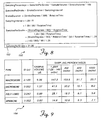
- FIGURE 9 shows a table 154 that illustrates the sample volume for a stroke (pumping cycle) of 75 micro liters ( ⁇ l) for several different types of tubing having different internal diameters. Also, the sampling percentages for different flow rates through the tubing are displayed.
- FIGURE 10 illustrates a table 156 that lists variables and their corresponding definitions. These variables are employed by controller 162 for controlling air bubble sensor 176. All volumes are calculated in units of 0.1 micro liters ( ⁇ l) and the signal readings of air bubble sensor 176 are in units of the difference (in ADC counts) between post-trigger and pre-trigger readings, unless otherwise specified (the trigger occurs when transmitter 104a produces an ultrasonic pulse for sensing by receiver 104b).
- FIGURE 11 shows an overview 200 of the steps employed to initialize the values of variables described in FIGURE 10, which are employed to control air bubble sensor 176.
- the logic moves from a start block to a decision block 202 and determines whether the air_alarm flag is clear. If not, the logic loops until the air_alarm flag is cleared. Once this flag is cleared, the logic steps to a block 204 in which an air_bubble variable 207 is set equal to zero. The logic advances to a block 206 in which a liquid_bubble variable 209 is set equal to zero. Moving to a block 208. the logic sets a previous_volume variable 205 equal to the value of a volume variable 203. Thereafter, the logic terminates
- an overview 220 illustrates the steps that are optionally employed at least once every second that pumping cassette 114 is latched into the interior of pump chassis 112. These steps reduce false alarms by "relatively” adjusting the values of several variables described in table 156 of FIGURE 10 to compensate for minor contamination of the exterior surface of the portion of distal tubing 118 monitored by air bubble sensor 176. These relative adjustments (if implemented) can finesse minor irregularities in pumping or smaller amounts of contamination for a variety of different types of disposable pumping cassettes. However, predetermined set points that control the absolute/safe operation of the system are not adjusted. Instead, the present invention reduces the number of false alarms without reducing the safety provided by the absolute values.
- the system might normally detect values of 70 and 20 (i.e., of the signal produced by receiver 104b), as indicative of the presence in the distal tubing of fluid and air, respectively.
- values of 70 and 20 i.e., of the signal produced by receiver 104b
- these values may rise to 150 for fluid and 80 for air.
- the present invention compensates for these changes so long as the predetermined absolute values for the presence of fluid and air are not exceeded. e.g.. 200 for fluid and 130 for air. While a current embodiment that is soon to be commercially introduced will not includes this feature, in some cases it may be desirable to include these steps in the logic used with monitoring the air bubble sensor.
- the logic determines if power has been applied to the IV pump, i.e., to energize the motor. If false, the logic continuously loops until the determination is true. When the determination at decision block 222 is true, the logic steps to a block 224 and an air_signal_threshold variable 213 is set equal to a default_air_signal_threshold value.
- the logic fetches a signal reading for the signal output from air bubble sensor 176.
- the logic determines if the signal reading is greater than or equal to 90% and less than or equal to 140% of the value of factory_calibrated_normal_liquid_signal 219. If the signal reading is within this range, the logic steps to a block 230 and air_signal_threshold variable 213 is set equal to a value of 60% of the actual signal reading of the air bubble sensor 176. The logic then advances to a decision block 232 from block 230, and also proceeds to decision block 232 if the determination at decision block 228 was false (i.e.. the reading is outside the range).
- the signal reading of air bubble sensor 176 is compared to a value greater than 140% of the value of factory_calibrated_normal_liquid_signal 219. If the reading is greater than the factory_calibrated_normal_liquid_signal, the logic steps to a block 234, in which air_signal_threshold 213 is set equal to 60% of 140% (i.e., 84%) of factory_calibrated_normal_liquid_signal 219. Lastly, the logic returns to the main flow of the control logic. Also, if the determination at decision block 232 is false the logic returns to the main flow.
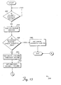
- a general overview 240 is shown of the logical steps performed each time during sampling interval (1.29/R) for air bubble sensor 176, using several of the variables defined in table 156 of FIGURE 10. From a start block, the logic advances to a decision block 242 and determines if volume variable 203 is equal to previous_volume variable 205. If not, the logic continuously loops until this determination is affirmative. Next, the logic steps to a block 244 in which a signal reading (resulting from an analog to digital conversion of the electrical signal produced by receiver 104b) from air bubble sensor 176 is fetched. Advancing to a decision block 246, the logic determines if the signal reading of air bubble sensor 176 is greater than a check_cassette_adc_value 221. If true, the logic moves to a block 248 and a check_cassette flag (alarm) is set on. Then, the logic advances to an exit block and terminates.
- a signal reading resulting from an analog to digital conversion of the electrical signal produced by receiver 104b
- the logic flows to a block 250 and delta variable 201 is set equal to the value of volume variable 203 minus the value of previous_volume variable 205.
- the value of previous_volume variable 205 is set equal to the value of volume variable 203.
- the logic next moves to a decision block 254 in which it determines if the signal reading of air bubble sensor 176 is greater than air_signal_threshold variable 215. If false, the logic flows to a block 256, and the air_bubble variable 207 is set equal to the value of delta 201 plus the prior value of air_bubble variable 207.
- the logic steps to a block 258 in which the air_bubble variable is set equal to the difference between its previous value and one-half the delta value.
- the logic then advances to a decision block 260, in which a determination is made as to whether air_bubble variable 207 is less than zero, and if so, the value of air_bubble is set equal to zero in a block 261. Thus, the value of the air_bubble variable is precluded from being negative. If the value of the air_bubble variable is not less than zero in decision block 260, or following block 261, the logic advances to the exit block (FIGURE 13).
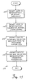
- a decision block 262 determines if the value of the air_bubble variable is greater than the air_volume_threshold value. If so, a block 264 provides for setting the air_alarm flag on. Otherwise, or following block 264, the logic terminates (in FIGURE 13).
- FIGURE 15 illustrates an overview 270 of the steps employed to provide absolute and calibration values for several variables defined in table 156 of FIGURE 10.
- the logic moves from a start block to a block 272 to provide an output on the display that prompts the user to enter a value for a default_air_signal_threshold variable 217.
- a block 274 another prompt is provided to the user to enter a value for factory_calibrated_normal_liquid_signal 219.
- the user is prompted to enter a maximum signal value produced by air bubble sensor 176, i.e.. the signal value generated prior to triggering output of an ultrasonic pulse from transmitter 104a to receiver 104b.
- the user is prompted to enter a maximum signal value produced by air bubble sensor 176 after the triggering of the ultrasonic pulse.
- the logic moves to the end block and returns to the main flow of logic.
Abstract
Description
Claims (11)
- A system (100) for automatically detecting a gas bubble in a liquid flowing through a tube (116, 118) of an intravenous line, comprising:characterised in that(a) a transmitter (1 04a) for generating an acoustic signal that is directed through a portion of the tube, the transmitter being disposed at one side of the tube, in contact therewith;(b) a receiver (104b) for receiving the acoustic signal and producing an electrical signal in response thereto, the receiver being in contact with an opposite side of the tube, directly opposite the transmitter; and(c) a pair of pivoting transducer members (1 02a, 102b), one member supporting the transmitter, another member supporting the receiver, the transmitter and the receiver being positioned in contact with the opposite sides of the tube, a magnitude of the electrical signal produced by the receiver indicating whether a gas bubble is disposed in the tube between the receiver and the transmitter;
the system further comprises a chassis (112) having opposite sides, each transducer member (102a, 102b) of said pair being pivotally coupled to and supported by the opposite sides of the chassis by respective hinge pins (106a, 106b), the pair of members being pivoted by the hinge pins, and the system further comprising a spring (140) for applying a biasing force to the members that automatically tends to keep the transmitter and the receiver in contact with the portion of the tube. - The system of Claim 1, further comprising a controller (162) that comprises:(a) a processor (166) the processor being coupled to the receiver to sample the electrical signal produced thereby; and(b) a memory (164) coupled to the processor, the memory storing machine instructions that define a plurality of functions that are implemented when the machine instructions are executed by the processor.
- The system of Claim 2, further comprising an input device (168).
- The system of Claim 2, further comprising an alarm that is activated when the electrical signal corresponds to a predetermined value.
- The system of Claim 2; wherein the controller is adapted to connect to a motor (136) of a pump, the controller only sampling the electrical signal when the motor is energized to actuate the pump.
- The system of Claim 5, wherein the transmitter and receiver are only energized to detect a gas bubble when the motor is energized to actuate the pump, and to determine if the pump is flooded when the motor is not moving.
- The system of Claim 1, wherein the spring (140) comprises at least one of a helical spring, a torsion spring and an elastomeric band.
- The system of claim 1, wherein the transducers are L-shaped.
- The system of claim 1, wherein the chassis is a pump chassis that has an interior and a longitudinal axis.
- The system of claim 9, further comprising elongate members (108a, 108b) pivotally connected to the pump chassis respectively at the opposite sides thereof so as to extend generally parallel to the longitudinal axis of the pump chassis, a cassette (114) connected to the tube and insertable into the interior of the pump chassis, and latches (110a, 110b) disposed on an inwardly facing surface of each elongate member (108a, 108b) for holding the cassette at a predetermined position within the pump chassis.
- The system of claim 10, wherein the transducers (102a, 102b) are free to pivot and move independently of the elongate members (108a, 108b).
Applications Claiming Priority (3)
| Application Number | Priority Date | Filing Date | Title |
|---|---|---|---|
| US09/097,068 US6142008A (en) | 1998-06-12 | 1998-06-12 | Air bubble sensor |
| US97068 | 1998-06-12 | ||
| PCT/US1999/012642 WO1999064093A1 (en) | 1998-06-12 | 1999-06-04 | Air bubble sensor |
Publications (2)
| Publication Number | Publication Date |
|---|---|
| EP1085922A1 EP1085922A1 (en) | 2001-03-28 |
| EP1085922B1 true EP1085922B1 (en) | 2005-09-14 |
Family
ID=22260791
Family Applications (1)
| Application Number | Title | Priority Date | Filing Date |
|---|---|---|---|
| EP99927282A Expired - Lifetime EP1085922B1 (en) | 1998-06-12 | 1999-06-04 | Air bubble sensor |
Country Status (9)
| Country | Link |
|---|---|
| US (1) | US6142008A (en) |
| EP (1) | EP1085922B1 (en) |
| JP (1) | JP2002517290A (en) |
| AT (1) | ATE304381T1 (en) |
| AU (1) | AU759455B2 (en) |
| CA (1) | CA2334295C (en) |
| DE (1) | DE69927263T2 (en) |
| ES (1) | ES2249009T3 (en) |
| WO (1) | WO1999064093A1 (en) |
Cited By (1)
| Publication number | Priority date | Publication date | Assignee | Title |
|---|---|---|---|---|
| US8844336B2 (en) | 2010-03-31 | 2014-09-30 | Zoll Lifebridge Gmbh | Air bubble sensor |
Families Citing this family (76)
| Publication number | Priority date | Publication date | Assignee | Title |
|---|---|---|---|---|
| US6616633B1 (en) * | 1997-09-19 | 2003-09-09 | Alaris Medical Systems, Inc. | Apparatus and method for air-in-line detection |
| US6554798B1 (en) | 1998-08-18 | 2003-04-29 | Medtronic Minimed, Inc. | External infusion device with remote programming, bolus estimator and/or vibration alarm capabilities |
| US6595035B1 (en) * | 2000-05-05 | 2003-07-22 | Jesco Products Company, Inc. | Sealant stream anomaly detecting assembly |
| US6622542B2 (en) * | 2001-03-20 | 2003-09-23 | Therox, Inc. | Bubble detector and method of use thereof |
| CA2489936A1 (en) * | 2002-07-09 | 2004-01-15 | Gambro Lundia Ab | A support element for an extracorporeal fluid transport line |
| US7278983B2 (en) | 2002-07-24 | 2007-10-09 | Medtronic Minimed, Inc. | Physiological monitoring device for controlling a medication infusion device |
| US20040068230A1 (en) | 2002-07-24 | 2004-04-08 | Medtronic Minimed, Inc. | System for providing blood glucose measurements to an infusion device |
| US9604014B2 (en) | 2004-05-21 | 2017-03-28 | Clearline Md, Llc | System for detecting and removing a gas bubble from a vascular infusion line |
| US7798996B1 (en) * | 2004-05-21 | 2010-09-21 | Anesthesia Safety Products, LLC. | System for detecting and removing a gas bubble from a vascular infusion line |
| US20070191990A1 (en) * | 2005-08-12 | 2007-08-16 | Hao Duan | Flow measurement and control with bubble detection |
| US20080103445A1 (en) * | 2006-09-29 | 2008-05-01 | Blaine David H | Method and Apparatus for Detecting Air Bubbles |
| US7726174B2 (en) | 2006-10-24 | 2010-06-01 | Zevex, Inc. | Universal air bubble detector |
| US8631683B2 (en) * | 2007-02-06 | 2014-01-21 | Fresenius Medical Care Holdings, Inc. | Dialysis systems including non-invasive multi-function sensor systems |
| US7661293B2 (en) * | 2007-02-06 | 2010-02-16 | Cosense, Inc. | Ultrasonic system for detecting and quantifying of air bubbles/particles in a flowing liquid |
| CN101715545B (en) * | 2007-05-25 | 2012-04-18 | 微动公司 | Vibratory flow meter and method for correcting for entrained gas in a flow material |
| US7981082B2 (en) * | 2007-08-21 | 2011-07-19 | Hospira, Inc. | System and method for reducing air bubbles in a fluid delivery line |
| AU2013201483B2 (en) * | 2007-08-21 | 2013-05-09 | Hospira, Inc. | System and method for reducing air bubbles in a fluid delivery line |
| EP2183564B1 (en) | 2007-08-24 | 2019-01-02 | Moog Inc. | Ultrasonic air and fluid detector |
| US8083503B2 (en) | 2007-09-27 | 2011-12-27 | Curlin Medical Inc. | Peristaltic pump assembly and regulator therefor |
| US7934912B2 (en) | 2007-09-27 | 2011-05-03 | Curlin Medical Inc | Peristaltic pump assembly with cassette and mounting pin arrangement |
| US8062008B2 (en) | 2007-09-27 | 2011-11-22 | Curlin Medical Inc. | Peristaltic pump and removable cassette therefor |
| US8033157B2 (en) | 2007-10-01 | 2011-10-11 | Baxter International Inc. | Medical fluid air bubble detection apparatus and method |
| US8728020B2 (en) | 2007-10-04 | 2014-05-20 | Gambro Lundia Ab | Infusion apparatus |
| EP2219533A4 (en) | 2007-12-07 | 2013-12-18 | Zevex Inc | Method of inducing transverse motion in langevin type transducers using split electroding of ceramic elements |
| US8517990B2 (en) | 2007-12-18 | 2013-08-27 | Hospira, Inc. | User interface improvements for medical devices |
| US8091442B1 (en) * | 2008-04-19 | 2012-01-10 | Cosense, Inc. | Positive tube retention arrangement |
| US8120500B2 (en) * | 2008-12-08 | 2012-02-21 | Ecolab Inc. | Acoustic fluid presence/absence detection |
| DK2198778T3 (en) * | 2008-12-19 | 2013-10-14 | Hoffmann La Roche | Infusion apparatus with impedance measurement |
| DE102008055167A1 (en) * | 2008-12-29 | 2010-07-01 | Endress + Hauser Flowtec Ag | Measuring system for determining and / or monitoring the flow of a measuring medium through the measuring tube by means of ultrasound |
| US8539812B2 (en) | 2009-02-06 | 2013-09-24 | Zevek, Inc. | Air bubble detector |
| CA2767007C (en) | 2009-07-01 | 2017-11-21 | Fresenius Medical Care Holdings, Inc. | Drug delivery devices and related systems and methods |
| US8753515B2 (en) | 2009-12-05 | 2014-06-17 | Home Dialysis Plus, Ltd. | Dialysis system with ultrafiltration control |
| US8197438B2 (en) * | 2009-12-23 | 2012-06-12 | Roche Diagnostics Operations, Inc. | Medicinal fluid delivery systems and methods for priming the same |
| US9518958B2 (en) | 2012-12-18 | 2016-12-13 | Deka Products Limited Partnership | System, method, and apparatus for detecting air in a fluid line using active rectification |
| US8501009B2 (en) | 2010-06-07 | 2013-08-06 | State Of Oregon Acting By And Through The State Board Of Higher Education On Behalf Of Oregon State University | Fluid purification system |
| WO2012106174A1 (en) | 2011-01-31 | 2012-08-09 | Fresenius Medical Care Holdings, Inc. | Preventing over-delivery of drug |
| US9987406B2 (en) | 2011-02-08 | 2018-06-05 | Fresenius Medical Care Holdings, Inc. | Magnetic sensors and related systems and methods |
| US8353870B2 (en) | 2011-04-26 | 2013-01-15 | Fresenius Medical Care Holdings, Inc. | Medical temperature sensors and related systems and methods |
| US9333286B2 (en) * | 2011-05-12 | 2016-05-10 | Fresenius Medical Care Holdings, Inc. | Medical tubing installation detection |
| US8836519B2 (en) | 2011-05-12 | 2014-09-16 | Fresenius Medical Care Holdings, Inc. | Determining the absence or presence of fluid in a dialysis system |
| NO333337B1 (en) * | 2011-08-02 | 2013-05-06 | Naxys As | Undervannsdetekteringsapparat |
| CA2844807C (en) | 2011-08-19 | 2022-07-26 | Hospira, Inc. | Systems and methods for a graphical interface including a graphical representation of medical data |
| AU2012315820B2 (en) * | 2011-09-30 | 2016-09-29 | Icu Medical, Inc. | Froth detection system and method |
| WO2013052680A2 (en) | 2011-10-07 | 2013-04-11 | Home Dialysis Plus, Ltd. | Heat exchange fluid purification for dialysis system |
| CN102366644A (en) * | 2011-10-23 | 2012-03-07 | 成都君晟科技有限公司 | Infusion device with automatic air embolism alarm function |
| US10022498B2 (en) | 2011-12-16 | 2018-07-17 | Icu Medical, Inc. | System for monitoring and delivering medication to a patient and method of using the same to minimize the risks associated with automated therapy |
| JP6306566B2 (en) * | 2012-03-30 | 2018-04-04 | アイシーユー・メディカル・インコーポレーテッド | Air detection system and method for detecting air in an infusion system pump |
| US9144646B2 (en) | 2012-04-25 | 2015-09-29 | Fresenius Medical Care Holdings, Inc. | Vial spiking devices and related assemblies and methods |
| ES2743160T3 (en) | 2012-07-31 | 2020-02-18 | Icu Medical Inc | Patient care system for critical medications |
| WO2014039835A1 (en) | 2012-09-06 | 2014-03-13 | Baxter International Inc. | Patient information software system including infusion map |
| JP6371773B2 (en) | 2012-11-13 | 2018-08-08 | バクスター・インターナショナル・インコーポレイテッドBaxter International Incorp0Rated | Infusion line management system |
| CA2891808C (en) | 2012-12-21 | 2020-12-01 | Alcon Research Ltd. | Cassette clamp mechanism |
| US9359885B2 (en) * | 2013-03-15 | 2016-06-07 | Baxter International Inc. | Acoustic line tracing system and method for fluid transfer system |
| WO2014190264A1 (en) | 2013-05-24 | 2014-11-27 | Hospira, Inc. | Multi-sensor infusion system for detecting air or an occlusion in the infusion system |
| ES2838450T3 (en) | 2013-05-29 | 2021-07-02 | Icu Medical Inc | Infusion set that uses one or more sensors and additional information to make an air determination relative to the infusion set |
| AU2014274122A1 (en) | 2013-05-29 | 2016-01-21 | Icu Medical, Inc. | Infusion system and method of use which prevents over-saturation of an analog-to-digital converter |
| EP3068464B1 (en) * | 2013-11-15 | 2024-04-10 | Fresenius Kabi USA, LLC | Fluid control system and disposable assembly |
| JP6636442B2 (en) | 2014-02-28 | 2020-01-29 | アイシーユー・メディカル・インコーポレーテッド | Infusion systems and methods utilizing dual wavelength optical in-pipe air detection |
| ES2864727T3 (en) | 2014-04-29 | 2021-10-14 | Outset Medical Inc | Dialysis system and methods |
| AU2015266706B2 (en) | 2014-05-29 | 2020-01-30 | Icu Medical, Inc. | Infusion system and pump with configurable closed loop delivery rate catch-up |
| US11344668B2 (en) | 2014-12-19 | 2022-05-31 | Icu Medical, Inc. | Infusion system with concurrent TPN/insulin infusion |
| US10850024B2 (en) | 2015-03-02 | 2020-12-01 | Icu Medical, Inc. | Infusion system, device, and method having advanced infusion features |
| EP3454922B1 (en) | 2016-05-13 | 2022-04-06 | ICU Medical, Inc. | Infusion pump system with common line auto flush |
| CA3027176A1 (en) | 2016-06-10 | 2017-12-14 | Icu Medical, Inc. | Acoustic flow sensor for continuous medication flow measurements and feedback control of infusion |
| ES2908601T3 (en) | 2016-08-19 | 2022-05-03 | Outset Medical Inc | Peritoneal dialysis system and methods |
| US11035829B2 (en) * | 2017-10-27 | 2021-06-15 | Olympus America Inc. | Dual ultrasonic probe with variable roof angle |
| US10089055B1 (en) | 2017-12-27 | 2018-10-02 | Icu Medical, Inc. | Synchronized display of screen content on networked devices |
| JP7178838B2 (en) * | 2018-09-11 | 2022-11-28 | 大研医器株式会社 | Connection member, pump casing and injection device provided with said connection member |
| CN109513066B (en) * | 2018-10-30 | 2020-12-01 | 青岛市精神卫生中心 | Drip controller |
| CN110327510B (en) * | 2019-08-13 | 2020-11-03 | 巨翊科技(上海)有限公司 | Infusion pump pipeline monitoring system |
| US11278671B2 (en) | 2019-12-04 | 2022-03-22 | Icu Medical, Inc. | Infusion pump with safety sequence keypad |
| CN113134129A (en) * | 2020-01-20 | 2021-07-20 | 深圳迈瑞科技有限公司 | Infusion pump and infusion pump bubble detection method |
| WO2022020184A1 (en) | 2020-07-21 | 2022-01-27 | Icu Medical, Inc. | Fluid transfer devices and methods of use |
| US11135360B1 (en) | 2020-12-07 | 2021-10-05 | Icu Medical, Inc. | Concurrent infusion with common line auto flush |
| CN112641502B (en) * | 2020-12-16 | 2022-02-15 | 杭州堃博生物科技有限公司 | Injection pump bubble emptying control method and device, injection pump and storage medium |
| US11712506B1 (en) * | 2022-08-24 | 2023-08-01 | Kyra Medical, Inc. | Fluid source management system |
Family Cites Families (60)
| Publication number | Priority date | Publication date | Assignee | Title |
|---|---|---|---|---|
| US3731679A (en) * | 1970-10-19 | 1973-05-08 | Sherwood Medical Ind Inc | Infusion system |
| US3699320A (en) * | 1971-01-18 | 1972-10-17 | Halliburton Co | Temperature compensated liquid metering system and method |
| US3768084A (en) * | 1972-07-14 | 1973-10-23 | Becton Dickinson Co | Particle counter having a clog and bubble alarm |
| US3990444A (en) * | 1972-11-22 | 1976-11-09 | Vial S.A.R.L. | Blood transfusion apparatus |
| GB1418181A (en) * | 1973-02-27 | 1975-12-17 | Cole E M | Ultrasonic detection of inclusions in a fluid flowing within a tube |
| US3898637A (en) * | 1973-07-27 | 1975-08-05 | Eugene B Wolstenholme | Detection means for gas entering human blood system from extra-corporeal tubing |
| US3854038A (en) * | 1973-08-27 | 1974-12-10 | Halliburton Co | Method and apparatus for compensating fluid flow for a variable physical condition |
| US3974681A (en) * | 1973-10-23 | 1976-08-17 | Jerry Namery | Ultrasonic bubble detector |
| US3935876A (en) * | 1974-11-15 | 1976-02-03 | Renal Systems, Inc. | Air leak detector |
| US4014206A (en) * | 1975-03-31 | 1977-03-29 | Akron City Hospital | Apparatus and method for monitoring air emboli during extracorporeal circulation |
| US4155362A (en) * | 1976-01-26 | 1979-05-22 | Baxter Travenol Laboratories, Inc. | Method and apparatus for metered infusion of fluids |
| US4068521A (en) * | 1976-07-22 | 1978-01-17 | Renal Systems, Inc. | Ultrasonic air and blood foam detector |
| US4114144A (en) * | 1976-08-12 | 1978-09-12 | Imed Corporation | Automatic air-in-line fluid detector |
| US4210138A (en) * | 1977-12-02 | 1980-07-01 | Baxter Travenol Laboratories, Inc. | Metering apparatus for a fluid infusion system with flow control station |
| US4213454A (en) * | 1977-12-02 | 1980-07-22 | Baxter Travenol Laboratories, Inc. | Control system for metering apparatus for a fluid infusion system |
| US4217993A (en) * | 1977-12-02 | 1980-08-19 | Baxter Travenol Laboratories, Inc. | Flow metering apparatus for a fluid infusion system |
| US4256437A (en) * | 1978-02-01 | 1981-03-17 | Stewart Naumann Laboratories, Inc. | Peristaltic infusion pump and method |
| US4280495A (en) * | 1978-11-24 | 1981-07-28 | Sarns, Inc. | Air emboli detection |
| US4319568A (en) * | 1979-10-29 | 1982-03-16 | Vickers Limited | Liquid dispensing apparatus |
| US4366384A (en) * | 1980-06-18 | 1982-12-28 | Cutter Laboratories, Inc. | Air bubble detector |
| US4367736A (en) * | 1980-08-25 | 1983-01-11 | Baxter Travenol Laboratories, Inc. | System for detecting bubble formation in clear and opaque fluids |
| US4394862A (en) * | 1980-08-25 | 1983-07-26 | Baxter Travenol Laboratories, Inc. | Metering apparatus with downline pressure monitoring system |
| US4444546A (en) * | 1980-09-19 | 1984-04-24 | Oximetrix, Inc. | Occlusion detection apparatus and method |
| US4418565A (en) * | 1980-12-03 | 1983-12-06 | Baxter Travenol Laboratories, Inc. | Ultrasonic bubble detector |
| US4447191A (en) * | 1981-12-15 | 1984-05-08 | Baxter Travenol Laboratories, Inc. | Control circuit for a blood fractionation apparatus |
| US4501531A (en) * | 1981-12-15 | 1985-02-26 | Baxter Travenol Laboratories, Inc. | Control circuit for a blood fractionation apparatus |
| US4515584A (en) * | 1982-07-06 | 1985-05-07 | Fujisawa Pharmaceutical Co., Ltd. | Artificial pancreas |
| US4487601A (en) * | 1983-06-20 | 1984-12-11 | Extracorporeal Medical Specialties, Inc. | Bubble detector circuit with variable reference level |
| US4496346A (en) * | 1983-08-17 | 1985-01-29 | Air-Shields, Inc. | Infusion monitoring apparatus |
| US4607520A (en) * | 1984-01-09 | 1986-08-26 | Introtek Corporation | Method and apparatus for detecting discontinuities in a fluid stream |
| GB8424101D0 (en) * | 1984-09-24 | 1984-10-31 | Vi Tal Hospital Products Ltd | Air-in-line detector |
| IT8453987V0 (en) * | 1984-10-31 | 1984-10-31 | Hospal Dasco Spa | DETECTOR DEVICE FOR THE PRESENCE OF FLUID IN CORRESPONDENCE WITH A PREFIXED LEVEL OF A LIQUID CONTAINER |
| US4658244A (en) * | 1985-03-28 | 1987-04-14 | Imed Corporation | Air-in-line detector |
| JPS6232969A (en) * | 1985-08-05 | 1987-02-12 | 日機装株式会社 | Infusion apparatus |
| DE3530747A1 (en) * | 1985-08-28 | 1987-03-05 | Stoeckert Instr Gmbh | ULTRASONIC SENSOR |
| US4648869A (en) * | 1985-12-04 | 1987-03-10 | American Hospital Supply Corporation | Automatic infiltration detection system and method |
| US4821558A (en) * | 1987-05-01 | 1989-04-18 | Abbott Laboratories | Ultrasonic detector |
| US4919596A (en) * | 1987-12-04 | 1990-04-24 | Pacesetter Infusion, Ltd. | Fluid delivery control and monitoring apparatus for a medication infusion system |
| US4874359A (en) * | 1987-12-14 | 1989-10-17 | White Frederick R | Power infuser |
| US5026348A (en) * | 1988-06-06 | 1991-06-25 | The General Hospital Corporation | Apparatus and method for the detection of IV catheter obstruction and extravasation |
| US4884065A (en) * | 1988-06-13 | 1989-11-28 | Pacesetter Infusion, Ltd. | Monitor for detecting tube position and air bubbles in tube |
| PL159857B1 (en) * | 1989-01-20 | 1993-01-29 | Method for the continuous control of the carried infusion microbatcher | |
| JPH061152Y2 (en) * | 1989-04-28 | 1994-01-12 | シャープ株式会社 | Infusion pump air detector |
| US5053747A (en) * | 1989-09-05 | 1991-10-01 | Pacesetter Infusion, Inc. | Ultrasonic air-in-line detector self-test technique |
| US5064412A (en) * | 1989-09-05 | 1991-11-12 | Pacesetter Infusion, Ltd. | Ultrasonic air-in-line detector for a medication infusion system |
| US5176631A (en) * | 1989-09-05 | 1993-01-05 | Pacesetter Infusion, Ltd. | Ultrasonic air-in-line detector for detecting entrained air in a medication infusion system |
| US5000663A (en) * | 1989-09-05 | 1991-03-19 | Pacesetter Infusion, Ltd. | Automatic tubing lock for ultrasonic sensor interface |
| US4981467A (en) * | 1990-02-27 | 1991-01-01 | Baxter International Inc. | Apparatus and method for the detection of air in fluid delivery systems |
| DE4013402C2 (en) * | 1990-04-26 | 1994-03-24 | Infurex Ag Cham | Method and device for detecting gas bubbles in a line filled with liquid, in particular a flexible, tubular line or a container |
| US5043706A (en) * | 1990-10-19 | 1991-08-27 | Eastman Kodak Company | System and method for detecting bubbles in a flowing fluid |
| JPH0693916B2 (en) * | 1990-10-31 | 1994-11-24 | テルモ株式会社 | Infusion pump |
| US5123275A (en) * | 1990-12-07 | 1992-06-23 | Ivac Corporation | Air in-line sensor system |
| JP3138065B2 (en) * | 1991-09-04 | 2001-02-26 | シャープ株式会社 | Sampling method of bubble detector in infusion device |
| GB2273533B (en) * | 1992-12-18 | 1996-09-25 | Minnesota Mining & Mfg | Pumping cassette with integral manifold |
| US5394732A (en) * | 1993-09-10 | 1995-03-07 | Cobe Laboratories, Inc. | Method and apparatus for ultrasonic detection of air bubbles |
| DE69411951T2 (en) * | 1993-12-30 | 1999-01-07 | Sims Graseby Ltd | MEDICAL INFUSION PUMP |
| ATE245040T1 (en) * | 1994-05-13 | 2003-08-15 | Abbott Lab | DISPOSABLE INFUSION CASSETTE WITH A PUSH-BUTTON OPERATED APSOCKET VALVE |
| US5537853A (en) * | 1994-09-12 | 1996-07-23 | Ivac Corporation | Air-in-line sensing apparatus |
| US5843035A (en) * | 1996-04-10 | 1998-12-01 | Baxter International Inc. | Air detector for intravenous infusion system |
| US5868712A (en) * | 1997-06-12 | 1999-02-09 | Abbott Laboratories | Pump with door-mounted mechanism for positioning tubing in the pump housing |
-
1998
- 1998-06-12 US US09/097,068 patent/US6142008A/en not_active Expired - Lifetime
-
1999
- 1999-06-04 CA CA002334295A patent/CA2334295C/en not_active Expired - Fee Related
- 1999-06-04 EP EP99927282A patent/EP1085922B1/en not_active Expired - Lifetime
- 1999-06-04 AT AT99927282T patent/ATE304381T1/en not_active IP Right Cessation
- 1999-06-04 JP JP2000553160A patent/JP2002517290A/en active Pending
- 1999-06-04 DE DE69927263T patent/DE69927263T2/en not_active Expired - Lifetime
- 1999-06-04 WO PCT/US1999/012642 patent/WO1999064093A1/en active IP Right Grant
- 1999-06-04 ES ES99927282T patent/ES2249009T3/en not_active Expired - Lifetime
- 1999-06-04 AU AU44224/99A patent/AU759455B2/en not_active Ceased
Cited By (1)
| Publication number | Priority date | Publication date | Assignee | Title |
|---|---|---|---|---|
| US8844336B2 (en) | 2010-03-31 | 2014-09-30 | Zoll Lifebridge Gmbh | Air bubble sensor |
Also Published As
| Publication number | Publication date |
|---|---|
| DE69927263T2 (en) | 2006-06-22 |
| US6142008A (en) | 2000-11-07 |
| CA2334295C (en) | 2008-12-09 |
| ES2249009T3 (en) | 2006-03-16 |
| JP2002517290A (en) | 2002-06-18 |
| CA2334295A1 (en) | 1999-12-16 |
| DE69927263D1 (en) | 2005-10-20 |
| WO1999064093A1 (en) | 1999-12-16 |
| AU4422499A (en) | 1999-12-30 |
| AU759455B2 (en) | 2003-04-17 |
| EP1085922A1 (en) | 2001-03-28 |
| ATE304381T1 (en) | 2005-09-15 |
Similar Documents
| Publication | Publication Date | Title |
|---|---|---|
| EP1085922B1 (en) | Air bubble sensor | |
| AU765163B2 (en) | Occlusion detection system | |
| EP0419094B1 (en) | Ultrasonic air-in-line detector for a medication infusion system | |
| EP0453211B1 (en) | Ultrasonic air-in-line detector for detecting air in a medication infusion system | |
| JP3670293B2 (en) | Upstream blockage detection system | |
| JP3262336B2 (en) | Device for monitoring blood chemistry | |
| EP0248632B1 (en) | Intravenous fluid flow monitor | |
| EP1751639B1 (en) | Flow monitoring system for a flow control apparatus | |
| AU697232B2 (en) | In situ calibration system for sensors located in a physiologic line | |
| EP0276535B1 (en) | Instrument for measuring living body components | |
| AU2008288910A1 (en) | System and method for reducing air bubbles in a fluid delivery line | |
| JP2001021572A (en) | Method for confirming aspirated volume of fluid | |
| EP0052004A1 (en) | System and method for controlling and monitoring blood or biologic fluid flow | |
| JPS6344390B2 (en) | ||
| JPS6344389B2 (en) | ||
| JP7387644B2 (en) | Processing apparatus and method with level control of gas separation devices | |
| JPH0542210A (en) | Transfusion device | |
| JPH0542211A (en) | Transfusion device | |
| AU2013201483B2 (en) | System and method for reducing air bubbles in a fluid delivery line | |
| CN116785533A (en) | Method and system for detecting needle falling off | |
| JPS647791B2 (en) | ||
| JP2003057253A (en) | Automatic dispensing apparatus |
Legal Events
| Date | Code | Title | Description |
|---|---|---|---|
| PUAI | Public reference made under article 153(3) epc to a published international application that has entered the european phase |
Free format text: ORIGINAL CODE: 0009012 |
|
| 17P | Request for examination filed |
Effective date: 20001212 |
|
| AK | Designated contracting states |
Kind code of ref document: A1 Designated state(s): AT BE CH CY DE DK ES FI FR GB GR IE IT LI LU NL PT SE |
|
| 17Q | First examination report despatched |
Effective date: 20030226 |
|
| RAP1 | Party data changed (applicant data changed or rights of an application transferred) |
Owner name: HOSPIRA, INC. |
|
| GRAP | Despatch of communication of intention to grant a patent |
Free format text: ORIGINAL CODE: EPIDOSNIGR1 |
|
| GRAS | Grant fee paid |
Free format text: ORIGINAL CODE: EPIDOSNIGR3 |
|
| GRAA | (expected) grant |
Free format text: ORIGINAL CODE: 0009210 |
|
| AK | Designated contracting states |
Kind code of ref document: B1 Designated state(s): AT BE CH CY DE DK ES FI FR GB GR IE IT LI LU NL PT SE |
|
| PG25 | Lapsed in a contracting state [announced via postgrant information from national office to epo] |
Ref country code: NL Free format text: LAPSE BECAUSE OF FAILURE TO SUBMIT A TRANSLATION OF THE DESCRIPTION OR TO PAY THE FEE WITHIN THE PRESCRIBED TIME-LIMIT Effective date: 20050914 Ref country code: LI Free format text: LAPSE BECAUSE OF FAILURE TO SUBMIT A TRANSLATION OF THE DESCRIPTION OR TO PAY THE FEE WITHIN THE PRESCRIBED TIME-LIMIT Effective date: 20050914 Ref country code: FI Free format text: LAPSE BECAUSE OF FAILURE TO SUBMIT A TRANSLATION OF THE DESCRIPTION OR TO PAY THE FEE WITHIN THE PRESCRIBED TIME-LIMIT Effective date: 20050914 Ref country code: CH Free format text: LAPSE BECAUSE OF FAILURE TO SUBMIT A TRANSLATION OF THE DESCRIPTION OR TO PAY THE FEE WITHIN THE PRESCRIBED TIME-LIMIT Effective date: 20050914 Ref country code: BE Free format text: LAPSE BECAUSE OF FAILURE TO SUBMIT A TRANSLATION OF THE DESCRIPTION OR TO PAY THE FEE WITHIN THE PRESCRIBED TIME-LIMIT Effective date: 20050914 Ref country code: AT Free format text: LAPSE BECAUSE OF FAILURE TO SUBMIT A TRANSLATION OF THE DESCRIPTION OR TO PAY THE FEE WITHIN THE PRESCRIBED TIME-LIMIT Effective date: 20050914 |
|
| REG | Reference to a national code |
Ref country code: GB Ref legal event code: FG4D |
|
| REG | Reference to a national code |
Ref country code: CH Ref legal event code: EP |
|
| REG | Reference to a national code |
Ref country code: IE Ref legal event code: FG4D |
|
| REF | Corresponds to: |
Ref document number: 69927263 Country of ref document: DE Date of ref document: 20051020 Kind code of ref document: P |
|
| PG25 | Lapsed in a contracting state [announced via postgrant information from national office to epo] |
Ref country code: SE Free format text: LAPSE BECAUSE OF FAILURE TO SUBMIT A TRANSLATION OF THE DESCRIPTION OR TO PAY THE FEE WITHIN THE PRESCRIBED TIME-LIMIT Effective date: 20051214 Ref country code: GR Free format text: LAPSE BECAUSE OF FAILURE TO SUBMIT A TRANSLATION OF THE DESCRIPTION OR TO PAY THE FEE WITHIN THE PRESCRIBED TIME-LIMIT Effective date: 20051214 Ref country code: DK Free format text: LAPSE BECAUSE OF FAILURE TO SUBMIT A TRANSLATION OF THE DESCRIPTION OR TO PAY THE FEE WITHIN THE PRESCRIBED TIME-LIMIT Effective date: 20051214 |
|
| PG25 | Lapsed in a contracting state [announced via postgrant information from national office to epo] |
Ref country code: PT Free format text: LAPSE BECAUSE OF FAILURE TO SUBMIT A TRANSLATION OF THE DESCRIPTION OR TO PAY THE FEE WITHIN THE PRESCRIBED TIME-LIMIT Effective date: 20060214 |
|
| NLV1 | Nl: lapsed or annulled due to failure to fulfill the requirements of art. 29p and 29m of the patents act | ||
| REG | Reference to a national code |
Ref country code: ES Ref legal event code: FG2A Ref document number: 2249009 Country of ref document: ES Kind code of ref document: T3 |
|
| REG | Reference to a national code |
Ref country code: CH Ref legal event code: PL |
|
| ET | Fr: translation filed | ||
| PLBE | No opposition filed within time limit |
Free format text: ORIGINAL CODE: 0009261 |
|
| STAA | Information on the status of an ep patent application or granted ep patent |
Free format text: STATUS: NO OPPOSITION FILED WITHIN TIME LIMIT |
|
| 26N | No opposition filed |
Effective date: 20060615 |
|
| PG25 | Lapsed in a contracting state [announced via postgrant information from national office to epo] |
Ref country code: LU Free format text: LAPSE BECAUSE OF NON-PAYMENT OF DUE FEES Effective date: 20060604 |
|
| PG25 | Lapsed in a contracting state [announced via postgrant information from national office to epo] |
Ref country code: CY Free format text: LAPSE BECAUSE OF FAILURE TO SUBMIT A TRANSLATION OF THE DESCRIPTION OR TO PAY THE FEE WITHIN THE PRESCRIBED TIME-LIMIT Effective date: 20050914 |
|
| PGFP | Annual fee paid to national office [announced via postgrant information from national office to epo] |
Ref country code: IE Payment date: 20090423 Year of fee payment: 11 |
|
| REG | Reference to a national code |
Ref country code: IE Ref legal event code: MM4A |
|
| PG25 | Lapsed in a contracting state [announced via postgrant information from national office to epo] |
Ref country code: IE Free format text: LAPSE BECAUSE OF NON-PAYMENT OF DUE FEES Effective date: 20100604 |
|
| PGFP | Annual fee paid to national office [announced via postgrant information from national office to epo] |
Ref country code: FR Payment date: 20120614 Year of fee payment: 14 Ref country code: GB Payment date: 20120525 Year of fee payment: 14 |
|
| PGFP | Annual fee paid to national office [announced via postgrant information from national office to epo] |
Ref country code: IT Payment date: 20120619 Year of fee payment: 14 |
|
| PGFP | Annual fee paid to national office [announced via postgrant information from national office to epo] |
Ref country code: DE Payment date: 20120629 Year of fee payment: 14 Ref country code: ES Payment date: 20120618 Year of fee payment: 14 |
|
| GBPC | Gb: european patent ceased through non-payment of renewal fee |
Effective date: 20130604 |
|
| REG | Reference to a national code |
Ref country code: DE Ref legal event code: R119 Ref document number: 69927263 Country of ref document: DE Effective date: 20140101 |
|
| REG | Reference to a national code |
Ref country code: FR Ref legal event code: ST Effective date: 20140228 |
|
| PG25 | Lapsed in a contracting state [announced via postgrant information from national office to epo] |
Ref country code: DE Free format text: LAPSE BECAUSE OF NON-PAYMENT OF DUE FEES Effective date: 20140101 Ref country code: GB Free format text: LAPSE BECAUSE OF NON-PAYMENT OF DUE FEES Effective date: 20130604 |
|
| PG25 | Lapsed in a contracting state [announced via postgrant information from national office to epo] |
Ref country code: IT Free format text: LAPSE BECAUSE OF NON-PAYMENT OF DUE FEES Effective date: 20130604 Ref country code: FR Free format text: LAPSE BECAUSE OF NON-PAYMENT OF DUE FEES Effective date: 20130701 |
|
| REG | Reference to a national code |
Ref country code: ES Ref legal event code: FD2A Effective date: 20140707 |
|
| PG25 | Lapsed in a contracting state [announced via postgrant information from national office to epo] |
Ref country code: ES Free format text: LAPSE BECAUSE OF NON-PAYMENT OF DUE FEES Effective date: 20130605 |