EP1087142B1 - Scroll compressor capacity control - Google Patents
Scroll compressor capacity control Download PDFInfo
- Publication number
- EP1087142B1 EP1087142B1 EP00308176A EP00308176A EP1087142B1 EP 1087142 B1 EP1087142 B1 EP 1087142B1 EP 00308176 A EP00308176 A EP 00308176A EP 00308176 A EP00308176 A EP 00308176A EP 1087142 B1 EP1087142 B1 EP 1087142B1
- Authority
- EP
- European Patent Office
- Prior art keywords
- scroll
- type machine
- machine according
- fluid
- valve
- Prior art date
- Legal status (The legal status is an assumption and is not a legal conclusion. Google has not performed a legal analysis and makes no representation as to the accuracy of the status listed.)
- Expired - Lifetime
Links
Images


Classifications
-
- F—MECHANICAL ENGINEERING; LIGHTING; HEATING; WEAPONS; BLASTING
- F01—MACHINES OR ENGINES IN GENERAL; ENGINE PLANTS IN GENERAL; STEAM ENGINES
- F01C—ROTARY-PISTON OR OSCILLATING-PISTON MACHINES OR ENGINES
- F01C1/00—Rotary-piston machines or engines
- F01C1/02—Rotary-piston machines or engines of arcuate-engagement type, i.e. with circular translatory movement of co-operating members, each member having the same number of teeth or tooth-equivalents
- F01C1/04—Rotary-piston machines or engines of arcuate-engagement type, i.e. with circular translatory movement of co-operating members, each member having the same number of teeth or tooth-equivalents of internal-axis type
-
- F—MECHANICAL ENGINEERING; LIGHTING; HEATING; WEAPONS; BLASTING
- F01—MACHINES OR ENGINES IN GENERAL; ENGINE PLANTS IN GENERAL; STEAM ENGINES
- F01C—ROTARY-PISTON OR OSCILLATING-PISTON MACHINES OR ENGINES
- F01C21/00—Component parts, details or accessories not provided for in groups F01C1/00 - F01C20/00
- F01C21/10—Outer members for co-operation with rotary pistons; Casings
- F01C21/104—Stators; Members defining the outer boundaries of the working chamber
- F01C21/108—Stators; Members defining the outer boundaries of the working chamber with an axial surface, e.g. side plates
-
- F—MECHANICAL ENGINEERING; LIGHTING; HEATING; WEAPONS; BLASTING
- F01—MACHINES OR ENGINES IN GENERAL; ENGINE PLANTS IN GENERAL; STEAM ENGINES
- F01C—ROTARY-PISTON OR OSCILLATING-PISTON MACHINES OR ENGINES
- F01C21/00—Component parts, details or accessories not provided for in groups F01C1/00 - F01C20/00
- F01C21/10—Outer members for co-operation with rotary pistons; Casings
-
- F—MECHANICAL ENGINEERING; LIGHTING; HEATING; WEAPONS; BLASTING
- F04—POSITIVE - DISPLACEMENT MACHINES FOR LIQUIDS; PUMPS FOR LIQUIDS OR ELASTIC FLUIDS
- F04C—ROTARY-PISTON, OR OSCILLATING-PISTON, POSITIVE-DISPLACEMENT MACHINES FOR LIQUIDS; ROTARY-PISTON, OR OSCILLATING-PISTON, POSITIVE-DISPLACEMENT PUMPS
- F04C18/00—Rotary-piston pumps specially adapted for elastic fluids
- F04C18/02—Rotary-piston pumps specially adapted for elastic fluids of arcuate-engagement type, i.e. with circular translatory movement of co-operating members, each member having the same number of teeth or tooth-equivalents
- F04C18/0207—Rotary-piston pumps specially adapted for elastic fluids of arcuate-engagement type, i.e. with circular translatory movement of co-operating members, each member having the same number of teeth or tooth-equivalents both members having co-operating elements in spiral form
- F04C18/0215—Rotary-piston pumps specially adapted for elastic fluids of arcuate-engagement type, i.e. with circular translatory movement of co-operating members, each member having the same number of teeth or tooth-equivalents both members having co-operating elements in spiral form where only one member is moving
-
- F—MECHANICAL ENGINEERING; LIGHTING; HEATING; WEAPONS; BLASTING
- F04—POSITIVE - DISPLACEMENT MACHINES FOR LIQUIDS; PUMPS FOR LIQUIDS OR ELASTIC FLUIDS
- F04C—ROTARY-PISTON, OR OSCILLATING-PISTON, POSITIVE-DISPLACEMENT MACHINES FOR LIQUIDS; ROTARY-PISTON, OR OSCILLATING-PISTON, POSITIVE-DISPLACEMENT PUMPS
- F04C27/00—Sealing arrangements in rotary-piston pumps specially adapted for elastic fluids
- F04C27/005—Axial sealings for working fluid
-
- F—MECHANICAL ENGINEERING; LIGHTING; HEATING; WEAPONS; BLASTING
- F04—POSITIVE - DISPLACEMENT MACHINES FOR LIQUIDS; PUMPS FOR LIQUIDS OR ELASTIC FLUIDS
- F04C—ROTARY-PISTON, OR OSCILLATING-PISTON, POSITIVE-DISPLACEMENT MACHINES FOR LIQUIDS; ROTARY-PISTON, OR OSCILLATING-PISTON, POSITIVE-DISPLACEMENT PUMPS
- F04C28/00—Control of, monitoring of, or safety arrangements for, pumps or pumping installations specially adapted for elastic fluids
- F04C28/24—Control of, monitoring of, or safety arrangements for, pumps or pumping installations specially adapted for elastic fluids characterised by using valves controlling pressure or flow rate, e.g. discharge valves or unloading valves
- F04C28/26—Control of, monitoring of, or safety arrangements for, pumps or pumping installations specially adapted for elastic fluids characterised by using valves controlling pressure or flow rate, e.g. discharge valves or unloading valves using bypass channels
- F04C28/265—Control of, monitoring of, or safety arrangements for, pumps or pumping installations specially adapted for elastic fluids characterised by using valves controlling pressure or flow rate, e.g. discharge valves or unloading valves using bypass channels being obtained by displacing a lateral sealing face
-
- F—MECHANICAL ENGINEERING; LIGHTING; HEATING; WEAPONS; BLASTING
- F04—POSITIVE - DISPLACEMENT MACHINES FOR LIQUIDS; PUMPS FOR LIQUIDS OR ELASTIC FLUIDS
- F04C—ROTARY-PISTON, OR OSCILLATING-PISTON, POSITIVE-DISPLACEMENT MACHINES FOR LIQUIDS; ROTARY-PISTON, OR OSCILLATING-PISTON, POSITIVE-DISPLACEMENT PUMPS
- F04C2270/00—Control; Monitoring or safety arrangements
- F04C2270/58—Valve parameters
-
- F—MECHANICAL ENGINEERING; LIGHTING; HEATING; WEAPONS; BLASTING
- F25—REFRIGERATION OR COOLING; COMBINED HEATING AND REFRIGERATION SYSTEMS; HEAT PUMP SYSTEMS; MANUFACTURE OR STORAGE OF ICE; LIQUEFACTION SOLIDIFICATION OF GASES
- F25B—REFRIGERATION MACHINES, PLANTS OR SYSTEMS; COMBINED HEATING AND REFRIGERATION SYSTEMS; HEAT PUMP SYSTEMS
- F25B2400/00—General features or devices for refrigeration machines, plants or systems, combined heating and refrigeration systems or heat-pump systems, i.e. not limited to a particular subgroup of F25B
- F25B2400/13—Economisers
-
- F—MECHANICAL ENGINEERING; LIGHTING; HEATING; WEAPONS; BLASTING
- F25—REFRIGERATION OR COOLING; COMBINED HEATING AND REFRIGERATION SYSTEMS; HEAT PUMP SYSTEMS; MANUFACTURE OR STORAGE OF ICE; LIQUEFACTION SOLIDIFICATION OF GASES
- F25B—REFRIGERATION MACHINES, PLANTS OR SYSTEMS; COMBINED HEATING AND REFRIGERATION SYSTEMS; HEAT PUMP SYSTEMS
- F25B2600/00—Control issues
- F25B2600/02—Compressor control
- F25B2600/026—Compressor control by controlling unloaders
- F25B2600/0261—Compressor control by controlling unloaders external to the compressor
-
- F—MECHANICAL ENGINEERING; LIGHTING; HEATING; WEAPONS; BLASTING
- F25—REFRIGERATION OR COOLING; COMBINED HEATING AND REFRIGERATION SYSTEMS; HEAT PUMP SYSTEMS; MANUFACTURE OR STORAGE OF ICE; LIQUEFACTION SOLIDIFICATION OF GASES
- F25B—REFRIGERATION MACHINES, PLANTS OR SYSTEMS; COMBINED HEATING AND REFRIGERATION SYSTEMS; HEAT PUMP SYSTEMS
- F25B2600/00—Control issues
- F25B2600/25—Control of valves
- F25B2600/2509—Economiser valves
Definitions
- the present invention is related to scroll-type machinery. More particularly, the present invention is directed towards capacity modulation of scroll-type compressors.
- Scroll machines are becoming more and more popular for use as compressors in refrigeration systems as well as air conditioning and heat pump applications.
- the popularity of scroll machinery is primarily due to their capability for extremely efficient operation.
- these machines incorporate a pair of intermeshed spiral wraps, one of which is caused to orbit with respect to the other so as to define one or more moving chambers which progressively decrease in size as they travel from an outer suction port towards a center discharge port.
- An electric motor is normally provided which operates to drive the scroll members via a suitable drive shaft.
- these scroll machines are designed to have a fixed compression ratio.
- Air conditioning and refrigeration systems experience a wide range of loading requirements. Using a fixed compression ratio compressor to meet this wide range of loading requirements can present various problems to the designer of the system.
- One method of adapting the fixed compression ratio compressors to the wide range of loading requirements is to incorporate a capacity modulation system into the compressor. Capacity modulation has proven to be a desirable feature to incorporate into the air conditioning and refrigeration compressors in order to better accommodate the wide range of loading to which the systems may be subjected. Many different approaches have been utilized for providing this capacity modulation feature. These prior art systems have ranged from control of the suction inlet to bypassing compressed discharge gas directly back into the suction area of the compressor.
- capacity modulation has often been accomplished via a delayed suction approach which comprises providing ports at various positions along the route of the compression chambers which, when opened, allow the compression chambers formed between the intermeshing scroll wraps to communicate with the suction gas supply, thus delaying the point at which compression of the suction gas begins.
- This delayed suction method of capacity modulation actually reduces the compression ratio of the compressor. While such systems are effective at reducing the capacity of the compressor, they are only capable of providing a predetermined or stepped amount of compressor unloading. The amount of unloading or the size of the step is dependent upon the positioning of the unloading ports along the wraps or the compression process.
- EP-A-0 747 597 upon which the pre-characterising portion of appended claim 1 is based, describes a scroll-type machine which is particularly well suited for use as a compressor in refrigeration and air conditioning systems and incorporates an arrangement for modulating the capacity thereof.
- the capacity of the scroll-type machine is modulated by relative axial movement between the scroll members so as to form a leakage path across the wrap tips and opposed end plates.
- Scroll separation may be accomplished in a time pulsed manner to thereby enable a full range of modulation with the duration of the loading and unloading periods being selected to maximize the efficiency of the overall system.
- the present invention can overcome previous deficiencies by enabling an infinitely variable capacity modulation system which has the capability of modulating the capacity from 100% of full capacity down to virtually zero capacity utilizing only a single set of controls and by providing a self-centering sealing system to provide accurate alignement between piston and bore. Further, the system of the present invention can enable the operating efficiency of the compressor and/or refrigeration system to be maximized for any degree of compressor unloading desired.
- compressor unloading can be accomplished by cyclically effecting axial separation of the two scroll members during the operating cycle of the compressor. More specifically, the present invention provides an arrangement wherein one scroll member can be moved axially with respect to the other scroll member by a solenoid valve which operates in a pulsed width modulation mode.
- the pulsed width modulation operating mode for the solenoid valve provides a leakage path across the tips of the wraps from the higher compression pockets defined by the intermeshing scroll wraps to the lower compression pockets and ultimately back to suction.
- Scroll compressor 10 which includes the unique capacity control system in accordance with the present invention and which is designated generally by the reference numeral 10.
- Scroll compressor 10 is generally of the type described in Assignee's U.S. Patent No. 5,102,316, the disclosure of which is incorporated herein by reference.
- Scroll compressor 10 comprises an outer shell 12 within which is disposed a driving motor including a stator 14 and a rotor 16, a crankshaft 18 to which rotor 16 is secured, an upper bearing housing 20 and a lower bearing housing (not shown) for rotatably supporting crankshaft 18 and a compressor assembly 24.
- Compressor assembly 24 includes an orbiting scroll member 26 supported on upper bearing housing 20 and drivingly connected to crankshaft 18 via a crankpin 28 and a drive bushing 30.
- a non-orbiting scroll member 32 is positioned in meshing engagement with orbiting scroll member 26 and is axially movably secured to upper bearing housing 20 by means of a plurality of bolts 34 and associated sleeve members 36.
- An Oldham coupling 38 is provided which cooperates with scroll members 26 and 32 to prevent relative rotation therebetween.
- a partition plate 40 is provided adjacent the upper end of shell 12 and serves to divide the interior of shell 12 into a discharge chamber 42 at the upper end thereof and a suction chamber 44 at the lower end thereof.
- suction gas is drawn into suction chamber 44 of shell 12 via a suction fitting 46. From suction chamber 44, suction gas is sucked into compressor 24 through an inlet 48 provided in non-orbiting scroll member 32.
- the intermeshing scroll wraps provided on scroll members 26 and 32 define moving pockets of gas which progressively decrease in size as they move radially inwardly as a result of the orbiting motion of scroll member 26 thus compressing the suction gas entering via inlet 48.
- the compressed gas is then discharged into discharge chamber 42 through a hub 50 provided in scroll member 36 and a passage 52 formed in partition 40.
- a pressure responsive discharge valve 54 is preferably provided seated within hub 50.
- Non-orbiting scroll member 32 is also provided with an annular recess 56 formed in the upper surface thereof.
- a floating seal 58 is disposed within recess 56 and is biased by intermediate pressurized gas against partition 40 to seal suction chamber 44 from discharge chamber 42.
- a passage 60 extends through non-orbiting scroll member 32 to supply the intermediate pressurized gas to recess 56.
- a capacity control system 66 is shown in association with compressor 10.
- Control system 66 includes a discharge fitting 68, a piston 70, a shell fitting 72, a three-way solenoid valve 74, a control module 76 and a sensor array 78 having one or more appropriate sensors.
- Discharge fitting 68 is threadingly received or otherwise secured within hub 50.
- Discharge fitting 68 defines an internal cavity 80 and a plurality of discharge passages 82.
- Discharge valve 54 is disposed within cavity 80.
- discharge fitting 68 is assembled to piston 70 by first aligning a plurality of tabs 84 on discharge fitting 68 with a matching plurality of slots 86 formed in piston 70. Discharge fitting 68 is then rotated to the position shown in Figure 3 to misalign tabs 84 with slots 86. An alignment pin 88 maintains the misalignment between tabs 84 and slots 86 while a coil spring 90 biases the two components together.
- Shell fitting 72 is sealingly secured to shell 12 and slidingly receives piston 70.
- Piston 70 and shell fitting 72 define a pressure chamber 92.
- Pressure chamber 92 is fluidically connected to solenoid 74 by a tube 94.
- Solenoid valve 74 is also in fluid communication with discharge chamber 42 through a tube 96 and it is in fluid communication with suction fitting 46 and thus suction chamber 44 through a tube 98.
- a seal 100 is located between piston 70 and shell fitting 72.
- the combination of piston 70, seal 100 and shell fitting 72 provides a self-centering sealing system to provide accurate alignment between piston 70 and shell fitting 72.
- solenoid valve 74 is deactivated (or it is actuated) by control module 76 to the position shown in Figure 1. In this position, discharge chamber 42 is in direct communication with chamber 92 through tube 96, solenoid valve 74 and tube 94.
- the pressurized fluid at discharge pressure within chambers 42 and 92 will act against opposite sides of piston 70 thus allowing for the normal biasing of non-orbiting scroll member 32 towards orbiting scroll member 26 as shown in Figure 1 to sealingly engage the axial ends of each scroll member with the respective end plate of the opposite scroll member.
- the axial sealing of the two scroll members 26 and 32 causes compressor 24 to operate at 100% capacity.
- solenoid valve 74 In order to unload compressor 24, solenoid valve 74 will be actuated (or it is deactuated) by control module 76 to the position shown in Figure 2. In this position, suction chamber 44 is in direct communication with chamber 92 through suction fitting 46, tube 98, solenoid valve 74 and tube 94. With the discharge pressure pressurized fluid released to suction from chamber 92, the pressure differences on opposite sides of piston 70 will move non-orbiting scroll member 32 upward as shown in Figure 2 to separate the axial ends of the tips of each scroll member with its respective end plate to create a gap 102 which allows the higher pressurized pockets to bleed to the lower pressurized pockets and eventually to suction chamber 44.
- a wave spring 104 which is illustrated in Figure 9 maintains the sealing relationship between floating seal 58 and partition 40 during the modulation of non-orbiting scroll member 32.
- the creation of gap 102 will substantially eliminate continued compression of the suction gas.
- discharge valve 54 will move to its closed position thereby preventing the backflow of high pressurized fluid from discharge chamber 42 or the downstream refrigeration system.
- solenoid valve 74 will be deactuated (or it will be actuated) to the position shown in Figure 1 in which fluid communication between chamber 92 and discharge chamber 42 is again created. This again allows fluid at discharge pressure to react against piston 70 to axially engage scroll members 26 and 32. The axial sealing engagement recreates the compressing action of compressor 24.
- Control module 76 is in communication with sensor array 78 to provide the required information for control module 76 to determine the degree of unloading required for the particular conditions of the refrigeration system including scroll compressor 10 existing at that time. Based upon this information, control module 76 will operate solenoid valve 74 in a pulsed width modulation mode to alternately place chamber 92 in communication with discharge chamber 42 and suction chamber 44. The frequency with which solenoid 74 is operated in the pulsed width modulated mode will determine the percent capacity of operation of compressor 24. As the sensed conditions change, control module 76 will vary the frequency of operation for solenoid valve 74 and thus the relative time periods at which compressor 24 is operated in a loaded and unloaded condition. The varying of the frequency of operation of solenoid valve 74 can cause the operation of compressor between fully loaded or 100% capacity and completely unloaded or 0% capacity or at any of an infinite number of settings in between in response to system demands.
- Capacity control system 166 is also shown in association with compressor 10. Capacity control system 166 is similar to capacity control system 66 but it uses a two-way solenoid valve 174 instead of three-way solenoid valve 74. Control system 166 includes discharge fitting 68, a piston 170, shell fitting 72, solenoid valve 174, control module 76 and sensor array 78.
- Piston 170 is identical to piston 70 with the exception that piston 170 defines a passageway 106 and an orifice 108 which extend between pressure chamber 92 and discharge chamber 42.
- the incorporation of passageway 106 and orifice 108 allows the use of two-way solenoid 174 instead of three-way solenoid 74 and the elimination of tube 96.
- Seal 100 is located between piston 170 and seal fitting 72 to provide for the self-aligning sealing system for piston 170 and fitting 72.
- Solenoid 174 operates in a manner similar to solenoid 74. Pressure chamber 92 is fluidically connected to solenoid 174 by tube 94. Solenoid valve 174 is also in fluid communication with suction fitting 46 and thus suction chamber 44 by tube 98.
- solenoid valve 174 is deactivated (or it is activated) by control module 76 to block fluid flow between tubes 94 and tube 98.
- chamber 92 is in communication with discharge chamber 42 through passageway 106 and orifice 108.
- the pressurized fluid at discharge pressure within chambers 42 and 92 will act against opposite sides of piston 170 thus allowing for the normal biasing of non-orbiting scroll member 32 towards orbiting scroll member 26 to sealingly engage the axial ends of each scroll member with the respective end plate of the opposite scroll member.
- the axial sealing of the two scroll members 26 and 32 causes compressor 24 to operate at 100% capacity.
- solenoid valve 174 will be actuated (or it will be deactuated) by control module 76 to the position shown in Figure 4. In this position, suction chamber 44 is in direct communication with chamber 92 through suction fitting 46, tube 98, solenoid valve 174 and tube 94. With the discharge pressure pressurized fluid released to suction from chamber 92, the pressure differences on opposite sides of piston 170 will move non-orbiting scroll member 32 upward to separate the axial end of the tips of each scroll member with its respective end plate and the higher pressurized pockets will bleed to the lower pressurized pockets and eventually to suction chamber 44. Orifice 108 is incorporated to control the flow of discharge gas between discharge chamber 42 and chamber 92.
- Wave spring 104 is also incorporated in this embodiment to maintain the sealing relationship between floating seal 58 and partition 40 during modulation of non-orbiting scroll member 32.
- gap 102 When gap 102 is created the continued compression of the suction gas will be eliminated.
- discharge valve 54 When this unloading occurs, discharge valve 54 will move to its closed position thereby preventing the backflow of high pressurized fluid from discharge chamber 42 on the downstream refrigeration system.
- solenoid valve 174 When compression of the suction gas is to be resumed, solenoid valve 174 will be deactuated (or it will be actuated) to again block fluid flow between tubes 94 and 98 allowing chamber 92 to be pressurized by discharge chamber 42 through passageway 106 and orifice 108. Similar to the embodiment shown in Figures 1-3, control module 76 is in communication with sensor array 78 to provide the required information for control module 76 to determine the degree of unloading required and thus the frequency with which solenoid valve 174 is operated in the pulsed width modulation mode.
- FIG. 5 there is shown a scroll compressor which includes a unique capacity control system in accordance with another embodiment of the present invention and which is designated generally by the reference numeral 210.
- Scroll compressor 210 comprises an outer shell 212 within which is disposed a driving motor including a stator 214 and a rotor 216, a crankshaft 218 to which rotor 216 is secured, an upper bearing housing 220 and a lower bearing housing 222 for rotatably supporting crankshaft 218 and a compressor assembly 224.
- a driving motor including a stator 214 and a rotor 216, a crankshaft 218 to which rotor 216 is secured, an upper bearing housing 220 and a lower bearing housing 222 for rotatably supporting crankshaft 218 and a compressor assembly 224.
- Compressor assembly 224 includes an orbiting scroll member 226 supported on upper bearing housing 220 and drivingly connected to crankshaft 218 via a crankpin 228 and a drive bushing 230.
- a non-orbiting scroll member 232 is positioned in meshing engagement with orbiting scroll member 226 and is axially movably secured to upper bearing housing 220 by means of a plurality of bolts (not shown) and associated sleeve members (not shown).
- An Oldham coupling 238 is provided which cooperates with scroll members 226 and 232 to prevent relative rotation therebetween.
- a partition plate 240 is provided adjacent the upper end of shell 212 and serves to divide the interior of shell 212 into a discharge chamber 242 at the upper end thereof and a suction chamber 244 at the lower end thereof.
- suction gas is drawn into suction chamber 244 of shell 212 via a suction fitting 246. From suction chamber 244, suction gas is sucked into compressor 224 through an inlet 248 provided in non-orbiting scroll member 232.
- the intermeshing scroll wraps provided on scroll members 226 and 232 define moving pockets of gas which progressively decrease in size as they move radially inwardly as a result of the orbiting motion of scroll member 226 thus compressing the suction gas entering via inlet 248.
- the compressed gas is then discharged into discharge chamber 242 via a discharge port 250 provided in scroll member 236 and a passage 252 formed in partition 240.
- a pressure responsive discharge valve 254 is preferably provided seated within discharge port 250.
- Non-orbiting scroll member 232 is also provided with an annular recess 256 formed in the upper surface thereof.
- a floating seal 258 is disposed within recess 256 and is biased by intermediate pressurized gas against partition 240 to seal suction chamber 244 from discharge chamber 246.
- a passage 260 extends through non-orbiting scroll member 232 to supply the intermediate pressurized gas to recess 256.
- a capacity control system 266 is shown in association with compressor 210.
- Control system 266 includes a discharge fitting 268, a piston 270, a shell fitting 272, solenoid valve 174, control module 76 and sensor array 78 having one or more appropriate sensors.
- Discharge fitting 268 is threadingly received or otherwise secured within discharge port 250.
- Discharge fitting 268 defines an internal cavity 280 and a plurality of discharge passages 282.
- Discharge valve 254 is disposed below fitting 268 and below cavity 280.
- Discharge fitting 268 defines an annular flange 284. Seated against flange 284 is a lip seal 286 and a floating retainer 288. Piston 270 is press fit or otherwise secured to discharge fitting 268 and piston 270 defines an annular flange 290 which sandwiches seal 286 and retainer 288 between flange 290 and flange 284. Discharge fitting 268 defines passageway 106 and orifice 108 which extends through discharge fitting 268 to fluidically connect discharge chamber 242 with a pressure chamber 292 defined by discharge fitting 268, piston 270, seal 286, retainer 288 and shell 212.
- Shell fitting 272 is secured within a bore defined by shell 212 and slidingly receives the assembly of discharge fitting 268, piston 270, seal 286 and retainer 288.
- Pressure chamber 292 is fluidically connected to solenoid 174 by tube 94 and with suction fitting 246 and thus suction chamber 244 through tube 98 in a manner similar to that described above for control system 166.
- the combination of piston 270, seal 286 and floating retainer 288 provides a self-centering sealing system to provide accurate alignment with the internal bore of shell fitting 272.
- Seal 286 and floating retainer 288 include sufficient radial compliance such that any misalignment between the internal bore of fitting 272 and the internal bore of discharge port 250 within which discharge fitting 268 is secured is accommodated by seal 286 and floating retainer 288.
- solenoid valve 174 is deactivated (or it is activated) by control module 76 to block fluid flow between tubes 94 and tube 98.
- chamber 292 is in communication with discharge chamber 242 through passageway 106 and orifice 108.
- the pressurized fluid at discharge pressure within chambers 242 and 292 will act against opposite sides of piston 270 thus allowing for the normal biasing of non-orbiting scroll member 232 towards orbiting scroll member 226 to sealingly engage the axial ends of each scroll member with the respective end plate of the opposite scroll member.
- the axial sealing of the two scroll members 226 and 232 causes compressor 224 to operate at 100% capacity.
- solenoid valve 174 In order to unload compressor 224, solenoid valve 174 will be actuated (or it will be deactuated) by control module 76 to the position shown in Figure 4. In this position, suction chamber 244 is in direct communication with chamber 292 through suction fitting 246, tube 98, solenoid valve 174 and tube 94. With the discharge pressure pressurized fluid released to suction from chamber 292, the pressure difference on opposite sides of piston 270 will move non-orbiting scroll member 232 upward to separate the axial end of the tips of each scroll member with its respective end plate and the higher pressurized pockets will bleed to the lower pressurized pockets and eventually to suction chamber 244. Orifice 108 is incorporated to control the flow of discharge gas between discharge chamber 242 and chamber 292.
- Wave spring 104 is also incorporated in this embodiment to maintain the sealing relationship between floating seal 258 and partition 240 during modulation of non-orbiting scroll member 232.
- gap 102 When gap 102 is created the continued compression of the suction gas will be eliminated.
- discharge valve 254 When this unloading occurs, discharge valve 254 will move to its closed position thereby preventing the backflow of high pressurized fluid from discharge chamber 242 on the downstream refrigeration system.
- solenoid valve 174 When compression of the suction gas is to be resumed, solenoid valve 174 will be deactuated (or it will be actuated) to again block fluid flow between tubes 94 and 98 allowing chamber 292 to be pressurized by discharge chamber 242 through passageway 106 and orifice 108. Similar to the embodiment shown in Figures 1-3, control module 76 is in communication with sensor array 78 to provide the required information for control module 76 to determine the degree of unloading required and thus the frequency with which solenoid valve 174 is operated in the pulsed width modulation mode.
- Compressor 210 includes the capability of having fluid injected into the intermediate pressurized moving chambers at a point intermediate suction chamber 244 and discharge chamber 242.
- a fluid injection fitting 310 extends through shell 212 and is fluidically connected to an injection tube 312 which is in turn fluidically connected to an injection fitting 314 secured to non-orbiting scroll member 232.
- Non-orbiting scroll member 232 defines a pair of radial passages 316 each of which extend between injection fitting 314 and a pair of axial passages 318.
- Axial passages 318 are open to the moving chambers on opposite sides of non-orbiting scroll member 232 of compressor 224 to inject the fluid into these moving chambers as required by a control system as is well known in the art.
- Fitting 310 comprises an internal portion 320, and an external portion 322.
- Internal portion 320 includes an L-shaped passage 324 which sealingly receives injection tube 312 at one end.
- External portion 322 extends from the outside of shell 212 to the inside of shell 212 where it is unitary or integral with internal portion 320.
- a welding or brazing attachment 326 secures and seals fitting 310 to shell 212.
- External portion 322 defines a bore 330 which is an extension of L-shaped passage 324.
- External portion 322 also defines a cylindrical bore 332 to which the tubing of the refrigeration system is secured.
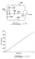
- Figure 14 illustrates a vapor injection system which provides the fluid for the fluid injection system of compressor 210.
- Compressor 210 is shown in a refrigeration system which includes a condenser 350, a first expansion valve or throttle 352, a flash tank or an economizer 354, a second expansion valve or throttle 356, an evaporator 358 and a series of piping 360 interconnecting the components as shown in Figure 14.
- Compressor 210 is operated by the motor to compress the refrigerant gas.
- the compressed gas is then liquified by condenser 350.
- the liquified refrigerant passes through expansion valve 352 and expands in flash tank 354 where it is separated into gas and liquid.
- the gaseous refrigerant further passes through piping 362 to be introduced into compressor 210 through fitting 310.
- the remaining liquid refrigerant further expands in expansion valve 356, is then vaporized in evaporator 358 and is again taken into compressor 210.
- flash tank 354 allows the capacity of the compressor to increase above the fixed capacity of compressor 210.
- the capacity of the compressor can be increased by approximately 20% to provide a compressor with 120% of its capacity as shown in the graph in Figure 16.
- a solenoid valve 364 is positioned within piping 362. The amount of percent increase in the capacity of compressor 210 can be controlled by operating solenoid valve 364 in a pulse width modulation mode. Solenoid valve 364 when operated in a pulse width modulation mode in combination with capacity control system 266 of compressor 210 allows the capacity of compressor 210 to be positioned anywhere along the line shown in Figure 16.
- FIG 15 illustrates a refrigerant system schematic in accordance with another embodiment of the present invention.
- the refrigerant system shown in Figure 15 is the same as the refrigerant system shown in Figure 14 except that flash tank 354 has been replaced by a heat exchanger 354'.
- Compressor 210 is operated by the motor to compress the refrigerant gas.
- the compressed gas is then liquified by condenser 350.
- the liquified refrigerant is then routed to the liquid side of heat exchanger 354' while a second portion of the liquified refrigerant passes through expansion valve 352 and then is routed to the vapor side of heat exchanger 354' in a gas and liquid state.
- the portion of refrigerant passing through expansion valve 352 is heated by the portion of refrigerant passing directly through heat exchanger to provide the vapor for injecting into compressor 210.
- This gaseous refrigerant then passes through piping 362 to be introduced into compressor 210 through fitting 310.
- the liquid refrigerant passing directly through heat exchanger 354' expands in expansion valve 356 and is then vaporized in evaporator 358 to again be taken into the suction side of compressor 210.
- solenoid valve 364 is positioned within piping 362 to allow the capacity of compressor 210 to be positioned anywhere along the line shown in Figure 16 when used in combination with capacity control system 266.
Description
- The present invention is related to scroll-type machinery. More particularly, the present invention is directed towards capacity modulation of scroll-type compressors.
- Scroll machines are becoming more and more popular for use as compressors in refrigeration systems as well as air conditioning and heat pump applications. The popularity of scroll machinery is primarily due to their capability for extremely efficient operation. Generally, these machines incorporate a pair of intermeshed spiral wraps, one of which is caused to orbit with respect to the other so as to define one or more moving chambers which progressively decrease in size as they travel from an outer suction port towards a center discharge port. An electric motor is normally provided which operates to drive the scroll members via a suitable drive shaft. During normal operation, these scroll machines are designed to have a fixed compression ratio.
- Air conditioning and refrigeration systems experience a wide range of loading requirements. Using a fixed compression ratio compressor to meet this wide range of loading requirements can present various problems to the designer of the system. One method of adapting the fixed compression ratio compressors to the wide range of loading requirements is to incorporate a capacity modulation system into the compressor. Capacity modulation has proven to be a desirable feature to incorporate into the air conditioning and refrigeration compressors in order to better accommodate the wide range of loading to which the systems may be subjected. Many different approaches have been utilized for providing this capacity modulation feature. These prior art systems have ranged from control of the suction inlet to bypassing compressed discharge gas directly back into the suction area of the compressor. With scroll-type compressors, capacity modulation has often been accomplished via a delayed suction approach which comprises providing ports at various positions along the route of the compression chambers which, when opened, allow the compression chambers formed between the intermeshing scroll wraps to communicate with the suction gas supply, thus delaying the point at which compression of the suction gas begins. This delayed suction method of capacity modulation actually reduces the compression ratio of the compressor. While such systems are effective at reducing the capacity of the compressor, they are only capable of providing a predetermined or stepped amount of compressor unloading. The amount of unloading or the size of the step is dependent upon the positioning of the unloading ports along the wraps or the compression process. While it is possible to provide multiple stepped unloading by incorporating a plurality of unloading ports at different locations along the compression process, this approach becomes more and more costly as the number of ports is increased and it requires additional space to accommodate the separate controls for opening and closing each individual on each set of ports.
- EP-A-0 747 597, upon which the pre-characterising portion of appended
claim 1 is based, describes a scroll-type machine which is particularly well suited for use as a compressor in refrigeration and air conditioning systems and incorporates an arrangement for modulating the capacity thereof. In one group of embodiments the capacity of the scroll-type machine is modulated by relative axial movement between the scroll members so as to form a leakage path across the wrap tips and opposed end plates. Scroll separation may be accomplished in a time pulsed manner to thereby enable a full range of modulation with the duration of the loading and unloading periods being selected to maximize the efficiency of the overall system. - According to the present invention, there is provided a scroll-type machine as defined in appended
claim 1. - The present invention can overcome previous deficiencies by enabling an infinitely variable capacity modulation system which has the capability of modulating the capacity from 100% of full capacity down to virtually zero capacity utilizing only a single set of controls and by providing a self-centering sealing system to provide accurate alignement between piston and bore. Further, the system of the present invention can enable the operating efficiency of the compressor and/or refrigeration system to be maximized for any degree of compressor unloading desired.
- In the present invention, compressor unloading can be accomplished by cyclically effecting axial separation of the two scroll members during the operating cycle of the compressor. More specifically, the present invention provides an arrangement wherein one scroll member can be moved axially with respect to the other scroll member by a solenoid valve which operates in a pulsed width modulation mode. The pulsed width modulation operating mode for the solenoid valve provides a leakage path across the tips of the wraps from the higher compression pockets defined by the intermeshing scroll wraps to the lower compression pockets and ultimately back to suction. By controlling the pulse width modulation frequency and thus the relative time between sealing and unsealing of the scroll wrap tips, infinite degrees of compressor unloading can be achieved with a single control system. Further, by sensing various conditions within the refrigeration system, the duration of compressor loading and unloading for each cycle can be selected for a given capacity such that overall system efficiency is maximized.
- The various embodiments of the present invention detailed below provide a wide variety of arrangements by which one scroll member may be axially reciprocated with respect to the other to accommodate a full range of compressor unloading. The ability to provide a full range of capacity modulation with a single control system as well as the ability to select the duration of loaded and unloaded operation cooperate to provide an extremely efficient system at a relatively low cost.
- Other advantages and objects of the present invention will become apparent to those skilled in the art from the subsequent detailed description, appended claims and drawings.
- In the drawings which illustrate the best mode presently contemplated for carrying out the present invention:
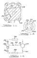
- Figure 1 is a section view of a scroll-type refrigeration compressor in accordance with the present invention operating at full capacity;
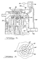
- Figure 2 is a section view of the scroll-type refrigeration shown in Figure 1 operating at a reduced capacity;
- Figure 3 is a detailed view of the ring and biasing arrangement taken in the direction of arrows 3-3 shown in Figure 2;
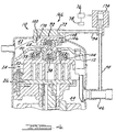
- Figure 4 is a section view of a scroll-type refrigeration compressor in accordance with another embodiment of the present invention operating at full capacity;
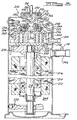
- Figure 5 is a section view of a scroll-type refrigeration compressor in accordance with another embodiment of the present invention;
- Figure 6 is a top section view of the compressor shown in Figure 5;
- Figure 7 is an enlarged section view of the piston assembly shown in Figure 5;
- Figure 8 is a top view of the discharge fitting shown in Figure 7;
- Figure 9 is an elevational view of the biasing spring shown in Figure 5;
- Figure 10 is a side view of the non-orbiting scroll member shown in Figure 5;
- Figure 11 is a cross sectional top view of the non-orbiting scroll member shown in Figure 10;
- Figure 12 is an enlarged sectional view of the injection fitting shown in Figure 5;
- Figure 13 is an end view of the fitting showing in Figure 12;
- Figure 14 is a schematic diagram of a refrigerant system utilizing the capacity control system in accordance with the present invention;
- Figure 15 is a schematic diagram of a refrigerant system in accordance with another embodiment of the present invention; and
- Figure 16 is a graph showing the capacity of the compressor using the capacity control system in accordance with the present invention.
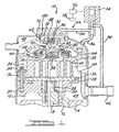
- Referring now to the drawings in which like reference numerals designate like or corresponding parts throughout the several views, there is shown in Figure 1 a scroll compressor which includes the unique capacity control system in accordance with the present invention and which is designated generally by the
reference numeral 10.Scroll compressor 10 is generally of the type described in Assignee's U.S. Patent No. 5,102,316, the disclosure of which is incorporated herein by reference.Scroll compressor 10 comprises anouter shell 12 within which is disposed a driving motor including astator 14 and arotor 16, acrankshaft 18 to whichrotor 16 is secured, an upper bearinghousing 20 and a lower bearing housing (not shown) for rotatably supportingcrankshaft 18 and acompressor assembly 24. -
Compressor assembly 24 includes an orbitingscroll member 26 supported on upper bearinghousing 20 and drivingly connected tocrankshaft 18 via acrankpin 28 and a drive bushing 30. Anon-orbiting scroll member 32 is positioned in meshing engagement with orbitingscroll member 26 and is axially movably secured to upper bearinghousing 20 by means of a plurality ofbolts 34 and associatedsleeve members 36. An Oldhamcoupling 38 is provided which cooperates withscroll members partition plate 40 is provided adjacent the upper end ofshell 12 and serves to divide the interior ofshell 12 into adischarge chamber 42 at the upper end thereof and asuction chamber 44 at the lower end thereof. - In operation, as orbiting
scroll member 26 orbits with respect tonon-orbiting scroll member 32, suction gas is drawn intosuction chamber 44 ofshell 12 via a suction fitting 46. Fromsuction chamber 44, suction gas is sucked intocompressor 24 through aninlet 48 provided innon-orbiting scroll member 32. The intermeshing scroll wraps provided onscroll members scroll member 26 thus compressing the suction gas entering viainlet 48. The compressed gas is then discharged intodischarge chamber 42 through ahub 50 provided inscroll member 36 and a passage 52 formed inpartition 40. A pressureresponsive discharge valve 54 is preferably provided seated withinhub 50. -
Non-orbiting scroll member 32 is also provided with anannular recess 56 formed in the upper surface thereof. A floatingseal 58 is disposed withinrecess 56 and is biased by intermediate pressurized gas againstpartition 40 to sealsuction chamber 44 fromdischarge chamber 42. Apassage 60 extends throughnon-orbiting scroll member 32 to supply the intermediate pressurized gas to recess 56. - A
capacity control system 66 is shown in association withcompressor 10.Control system 66 includes a discharge fitting 68, apiston 70, a shell fitting 72, a three-way solenoid valve 74, acontrol module 76 and asensor array 78 having one or more appropriate sensors. Discharge fitting 68 is threadingly received or otherwise secured withinhub 50. Discharge fitting 68 defines aninternal cavity 80 and a plurality ofdischarge passages 82.Discharge valve 54 is disposed withincavity 80. Thus, pressurized gas overcomes the biasing load ofdischarge valve 54 to opendischarge valve 54 and allowing the pressurized gas to flow intocavity 80, throughpassages 82 and intodischarge chamber 42. - Referring now to Figures 1 and 3, discharge fitting 68 is assembled to
piston 70 by first aligning a plurality oftabs 84 on discharge fitting 68 with a matching plurality ofslots 86 formed inpiston 70. Discharge fitting 68 is then rotated to the position shown in Figure 3 to misaligntabs 84 withslots 86. Analignment pin 88 maintains the misalignment betweentabs 84 andslots 86 while acoil spring 90 biases the two components together. - Shell fitting 72 is sealingly secured to shell 12 and slidingly receives
piston 70.Piston 70 and shell fitting 72 define apressure chamber 92.Pressure chamber 92 is fluidically connected to solenoid 74 by atube 94.Solenoid valve 74 is also in fluid communication withdischarge chamber 42 through a tube 96 and it is in fluid communication with suction fitting 46 and thussuction chamber 44 through atube 98. Aseal 100 is located betweenpiston 70 and shell fitting 72. The combination ofpiston 70,seal 100 and shell fitting 72 provides a self-centering sealing system to provide accurate alignment betweenpiston 70 and shell fitting 72. - In order to bias
non-orbiting scroll member 32 into sealing engagement with orbitingscroll member 26 for normal full load operation as shown in Figure 1,solenoid valve 74 is deactivated (or it is actuated) bycontrol module 76 to the position shown in Figure 1. In this position,discharge chamber 42 is in direct communication withchamber 92 through tube 96,solenoid valve 74 andtube 94. The pressurized fluid at discharge pressure withinchambers piston 70 thus allowing for the normal biasing ofnon-orbiting scroll member 32 towards orbitingscroll member 26 as shown in Figure 1 to sealingly engage the axial ends of each scroll member with the respective end plate of the opposite scroll member. The axial sealing of the twoscroll members causes compressor 24 to operate at 100% capacity. - In order to unload
compressor 24,solenoid valve 74 will be actuated (or it is deactuated) bycontrol module 76 to the position shown in Figure 2. In this position,suction chamber 44 is in direct communication withchamber 92 through suction fitting 46,tube 98,solenoid valve 74 andtube 94. With the discharge pressure pressurized fluid released to suction fromchamber 92, the pressure differences on opposite sides ofpiston 70 will movenon-orbiting scroll member 32 upward as shown in Figure 2 to separate the axial ends of the tips of each scroll member with its respective end plate to create agap 102 which allows the higher pressurized pockets to bleed to the lower pressurized pockets and eventually to suctionchamber 44. Awave spring 104 which is illustrated in Figure 9 maintains the sealing relationship between floatingseal 58 andpartition 40 during the modulation ofnon-orbiting scroll member 32. The creation ofgap 102 will substantially eliminate continued compression of the suction gas. When this unloading occurs,discharge valve 54 will move to its closed position thereby preventing the backflow of high pressurized fluid fromdischarge chamber 42 or the downstream refrigeration system. When compression of the suction gas is to be resumed,solenoid valve 74 will be deactuated (or it will be actuated) to the position shown in Figure 1 in which fluid communication betweenchamber 92 anddischarge chamber 42 is again created. This again allows fluid at discharge pressure to react againstpiston 70 to axially engagescroll members compressor 24. -
Control module 76 is in communication withsensor array 78 to provide the required information forcontrol module 76 to determine the degree of unloading required for the particular conditions of the refrigeration system includingscroll compressor 10 existing at that time. Based upon this information,control module 76 will operatesolenoid valve 74 in a pulsed width modulation mode to alternately placechamber 92 in communication withdischarge chamber 42 andsuction chamber 44. The frequency with whichsolenoid 74 is operated in the pulsed width modulated mode will determine the percent capacity of operation ofcompressor 24. As the sensed conditions change,control module 76 will vary the frequency of operation forsolenoid valve 74 and thus the relative time periods at whichcompressor 24 is operated in a loaded and unloaded condition. The varying of the frequency of operation ofsolenoid valve 74 can cause the operation of compressor between fully loaded or 100% capacity and completely unloaded or 0% capacity or at any of an infinite number of settings in between in response to system demands. - Referring now to Figure 4, there is shown a unique capacity control system in accordance with another embodiment of the present invention which is designated generally as
reference numeral 166.Capacity control system 166 is also shown in association withcompressor 10.Capacity control system 166 is similar tocapacity control system 66 but it uses a two-way solenoid valve 174 instead of three-way solenoid valve 74.Control system 166 includes discharge fitting 68, apiston 170, shell fitting 72,solenoid valve 174,control module 76 andsensor array 78. -
Piston 170 is identical topiston 70 with the exception thatpiston 170 defines apassageway 106 and anorifice 108 which extend betweenpressure chamber 92 anddischarge chamber 42. The incorporation ofpassageway 106 andorifice 108 allows the use of two-way solenoid 174 instead of three-way solenoid 74 and the elimination of tube 96. By eliminating tube 96, the fitting and hole throughshell 12 is also eliminated.Seal 100 is located betweenpiston 170 and seal fitting 72 to provide for the self-aligning sealing system forpiston 170 andfitting 72. -
Solenoid 174 operates in a manner similar tosolenoid 74.Pressure chamber 92 is fluidically connected to solenoid 174 bytube 94.Solenoid valve 174 is also in fluid communication with suction fitting 46 and thussuction chamber 44 bytube 98. - In order to bias
non-orbiting scroll member 32 into sealing engagement with orbitingscroll member 26 for normal full load operation,solenoid valve 174 is deactivated (or it is activated) bycontrol module 76 to block fluid flow betweentubes 94 andtube 98. In this position,chamber 92 is in communication withdischarge chamber 42 throughpassageway 106 andorifice 108. The pressurized fluid at discharge pressure withinchambers piston 170 thus allowing for the normal biasing ofnon-orbiting scroll member 32 towards orbitingscroll member 26 to sealingly engage the axial ends of each scroll member with the respective end plate of the opposite scroll member. The axial sealing of the twoscroll members causes compressor 24 to operate at 100% capacity. - In order to unload
compressor 24,solenoid valve 174 will be actuated (or it will be deactuated) bycontrol module 76 to the position shown in Figure 4. In this position,suction chamber 44 is in direct communication withchamber 92 through suction fitting 46,tube 98,solenoid valve 174 andtube 94. With the discharge pressure pressurized fluid released to suction fromchamber 92, the pressure differences on opposite sides ofpiston 170 will movenon-orbiting scroll member 32 upward to separate the axial end of the tips of each scroll member with its respective end plate and the higher pressurized pockets will bleed to the lower pressurized pockets and eventually to suctionchamber 44.Orifice 108 is incorporated to control the flow of discharge gas betweendischarge chamber 42 andchamber 92. Thus, whenchamber 92 is connected to the suction side of the compressor, the pressure difference on opposite sides ofpiston 170 will be created.Wave spring 104 is also incorporated in this embodiment to maintain the sealing relationship between floatingseal 58 andpartition 40 during modulation ofnon-orbiting scroll member 32. Whengap 102 is created the continued compression of the suction gas will be eliminated. When this unloading occurs,discharge valve 54 will move to its closed position thereby preventing the backflow of high pressurized fluid fromdischarge chamber 42 on the downstream refrigeration system. When compression of the suction gas is to be resumed,solenoid valve 174 will be deactuated (or it will be actuated) to again block fluid flow betweentubes chamber 92 to be pressurized bydischarge chamber 42 throughpassageway 106 andorifice 108. Similar to the embodiment shown in Figures 1-3,control module 76 is in communication withsensor array 78 to provide the required information forcontrol module 76 to determine the degree of unloading required and thus the frequency with whichsolenoid valve 174 is operated in the pulsed width modulation mode. - Referring now to Figure 5, there is shown a scroll compressor which includes a unique capacity control system in accordance with another embodiment of the present invention and which is designated generally by the
reference numeral 210. -
Scroll compressor 210 comprises anouter shell 212 within which is disposed a driving motor including astator 214 and arotor 216, acrankshaft 218 to whichrotor 216 is secured, anupper bearing housing 220 and alower bearing housing 222 for rotatably supportingcrankshaft 218 and acompressor assembly 224. -
Compressor assembly 224 includes anorbiting scroll member 226 supported onupper bearing housing 220 and drivingly connected to crankshaft 218 via acrankpin 228 and adrive bushing 230. Anon-orbiting scroll member 232 is positioned in meshing engagement with orbitingscroll member 226 and is axially movably secured toupper bearing housing 220 by means of a plurality of bolts (not shown) and associated sleeve members (not shown). AnOldham coupling 238 is provided which cooperates withscroll members partition plate 240 is provided adjacent the upper end ofshell 212 and serves to divide the interior ofshell 212 into adischarge chamber 242 at the upper end thereof and asuction chamber 244 at the lower end thereof. - In operation, as orbiting
scroll member 226 orbits with respect to scrollmember 232, suction gas is drawn intosuction chamber 244 ofshell 212 via asuction fitting 246. Fromsuction chamber 244, suction gas is sucked intocompressor 224 through aninlet 248 provided innon-orbiting scroll member 232. The intermeshing scroll wraps provided onscroll members scroll member 226 thus compressing the suction gas entering viainlet 248. The compressed gas is then discharged intodischarge chamber 242 via adischarge port 250 provided in scroll member 236 and apassage 252 formed inpartition 240. A pressureresponsive discharge valve 254 is preferably provided seated withindischarge port 250. -
Non-orbiting scroll member 232 is also provided with anannular recess 256 formed in the upper surface thereof. A floatingseal 258 is disposed withinrecess 256 and is biased by intermediate pressurized gas againstpartition 240 to sealsuction chamber 244 fromdischarge chamber 246. Apassage 260 extends throughnon-orbiting scroll member 232 to supply the intermediate pressurized gas to recess 256. - A
capacity control system 266 is shown in association withcompressor 210.Control system 266 includes a discharge fitting 268, apiston 270, a shell fitting 272,solenoid valve 174,control module 76 andsensor array 78 having one or more appropriate sensors. Discharge fitting 268 is threadingly received or otherwise secured withindischarge port 250. Discharge fitting 268 defines aninternal cavity 280 and a plurality ofdischarge passages 282.Discharge valve 254 is disposed below fitting 268 and belowcavity 280. Thus, pressurized gas overcomes the biasing load ofdischarge valve 254 to opendischarge valve 254 and allowing the pressurized gas to flow intocavity 280, throughpassages 282 and intodischarge chamber 242. - Referring now to Figures 5, 7 and 8, the assembly of discharge fitting 268 and
piston 270 is shown in greater detail. Discharge fitting 268 defines anannular flange 284. Seated againstflange 284 is alip seal 286 and a floatingretainer 288.Piston 270 is press fit or otherwise secured to discharge fitting 268 andpiston 270 defines anannular flange 290 which sandwichesseal 286 andretainer 288 betweenflange 290 andflange 284. Discharge fitting 268 definespassageway 106 andorifice 108 which extends through discharge fitting 268 to fluidically connectdischarge chamber 242 with a pressure chamber 292 defined by discharge fitting 268,piston 270,seal 286,retainer 288 andshell 212. Shell fitting 272 is secured within a bore defined byshell 212 and slidingly receives the assembly of discharge fitting 268,piston 270,seal 286 andretainer 288. Pressure chamber 292 is fluidically connected to solenoid 174 bytube 94 and with suction fitting 246 and thussuction chamber 244 throughtube 98 in a manner similar to that described above forcontrol system 166. The combination ofpiston 270,seal 286 and floatingretainer 288 provides a self-centering sealing system to provide accurate alignment with the internal bore of shell fitting 272.Seal 286 and floatingretainer 288 include sufficient radial compliance such that any misalignment between the internal bore of fitting 272 and the internal bore ofdischarge port 250 within which discharge fitting 268 is secured is accommodated byseal 286 and floatingretainer 288. - In order to bias
non-orbiting scroll member 232 into sealing engagement with orbitingscroll member 226 for normal full load operation,solenoid valve 174 is deactivated (or it is activated) bycontrol module 76 to block fluid flow betweentubes 94 andtube 98. In this position, chamber 292 is in communication withdischarge chamber 242 throughpassageway 106 andorifice 108. The pressurized fluid at discharge pressure withinchambers 242 and 292 will act against opposite sides ofpiston 270 thus allowing for the normal biasing ofnon-orbiting scroll member 232 towards orbitingscroll member 226 to sealingly engage the axial ends of each scroll member with the respective end plate of the opposite scroll member. The axial sealing of the twoscroll members compressor 224 to operate at 100% capacity. - In order to unload
compressor 224,solenoid valve 174 will be actuated (or it will be deactuated) bycontrol module 76 to the position shown in Figure 4. In this position,suction chamber 244 is in direct communication with chamber 292 through suction fitting 246,tube 98,solenoid valve 174 andtube 94. With the discharge pressure pressurized fluid released to suction from chamber 292, the pressure difference on opposite sides ofpiston 270 will movenon-orbiting scroll member 232 upward to separate the axial end of the tips of each scroll member with its respective end plate and the higher pressurized pockets will bleed to the lower pressurized pockets and eventually to suctionchamber 244.Orifice 108 is incorporated to control the flow of discharge gas betweendischarge chamber 242 and chamber 292. Thus, when chamber 292 is connected to the suction side of the compressor, the pressure difference on opposite sides ofpiston 270 will be created.Wave spring 104 is also incorporated in this embodiment to maintain the sealing relationship between floatingseal 258 andpartition 240 during modulation ofnon-orbiting scroll member 232. Whengap 102 is created the continued compression of the suction gas will be eliminated. When this unloading occurs,discharge valve 254 will move to its closed position thereby preventing the backflow of high pressurized fluid fromdischarge chamber 242 on the downstream refrigeration system. When compression of the suction gas is to be resumed,solenoid valve 174 will be deactuated (or it will be actuated) to again block fluid flow betweentubes discharge chamber 242 throughpassageway 106 andorifice 108. Similar to the embodiment shown in Figures 1-3,control module 76 is in communication withsensor array 78 to provide the required information forcontrol module 76 to determine the degree of unloading required and thus the frequency with whichsolenoid valve 174 is operated in the pulsed width modulation mode. - Referring now to Figures 6, 10 and 11, the fluid injection system for
compressor 210 is shown in greater detail.Compressor 210 includes the capability of having fluid injected into the intermediate pressurized moving chambers at a pointintermediate suction chamber 244 anddischarge chamber 242. A fluid injection fitting 310 extends throughshell 212 and is fluidically connected to aninjection tube 312 which is in turn fluidically connected to an injection fitting 314 secured tonon-orbiting scroll member 232.Non-orbiting scroll member 232 defines a pair ofradial passages 316 each of which extend between injection fitting 314 and a pair ofaxial passages 318.Axial passages 318 are open to the moving chambers on opposite sides ofnon-orbiting scroll member 232 ofcompressor 224 to inject the fluid into these moving chambers as required by a control system as is well known in the art. - Referring now to Figures 12 and 13, fitting 310 is shown in greater detail. Fitting 310 comprises an
internal portion 320, and anexternal portion 322.Internal portion 320 includes an L-shapedpassage 324 which sealingly receivesinjection tube 312 at one end.External portion 322 extends from the outside ofshell 212 to the inside ofshell 212 where it is unitary or integral withinternal portion 320. A welding orbrazing attachment 326 secures and seals fitting 310 to shell 212.External portion 322 defines abore 330 which is an extension of L-shapedpassage 324.External portion 322 also defines acylindrical bore 332 to which the tubing of the refrigeration system is secured. - Figure 14 illustrates a vapor injection system which provides the fluid for the fluid injection system of
compressor 210.Compressor 210 is shown in a refrigeration system which includes acondenser 350, a first expansion valve orthrottle 352, a flash tank or aneconomizer 354, a second expansion valve orthrottle 356, anevaporator 358 and a series of piping 360 interconnecting the components as shown in Figure 14.Compressor 210 is operated by the motor to compress the refrigerant gas. The compressed gas is then liquified bycondenser 350. The liquified refrigerant passes throughexpansion valve 352 and expands inflash tank 354 where it is separated into gas and liquid. The gaseous refrigerant further passes through piping 362 to be introduced intocompressor 210 throughfitting 310. On the other hand, the remaining liquid refrigerant further expands inexpansion valve 356, is then vaporized inevaporator 358 and is again taken intocompressor 210. - The incorporation of
flash tank 354 and the remainder of the vapor injection system, allows the capacity of the compressor to increase above the fixed capacity ofcompressor 210. Typically, at standard air conditioning conditions, the capacity of the compressor can be increased by approximately 20% to provide a compressor with 120% of its capacity as shown in the graph in Figure 16. In order to be able to control the capacity ofcompressor 210, asolenoid valve 364 is positioned withinpiping 362. The amount of percent increase in the capacity ofcompressor 210 can be controlled by operatingsolenoid valve 364 in a pulse width modulation mode.Solenoid valve 364 when operated in a pulse width modulation mode in combination withcapacity control system 266 ofcompressor 210 allows the capacity ofcompressor 210 to be positioned anywhere along the line shown in Figure 16. - Figure 15 illustrates a refrigerant system schematic in accordance with another embodiment of the present invention. The refrigerant system shown in Figure 15 is the same as the refrigerant system shown in Figure 14 except that
flash tank 354 has been replaced by a heat exchanger 354'.Compressor 210 is operated by the motor to compress the refrigerant gas. The compressed gas is then liquified bycondenser 350. The liquified refrigerant is then routed to the liquid side of heat exchanger 354' while a second portion of the liquified refrigerant passes throughexpansion valve 352 and then is routed to the vapor side of heat exchanger 354' in a gas and liquid state. The portion of refrigerant passing throughexpansion valve 352 is heated by the portion of refrigerant passing directly through heat exchanger to provide the vapor for injecting intocompressor 210. This gaseous refrigerant then passes through piping 362 to be introduced intocompressor 210 throughfitting 310. On the other hand, the liquid refrigerant passing directly through heat exchanger 354' expands inexpansion valve 356 and is then vaporized inevaporator 358 to again be taken into the suction side ofcompressor 210. Similar to the system shown in Figure 14,solenoid valve 364 is positioned within piping 362 to allow the capacity ofcompressor 210 to be positioned anywhere along the line shown in Figure 16 when used in combination withcapacity control system 266. - While the above detailed description describes the preferred embodiment of the present invention, it should be understood that the present invention is susceptible to modification, variation and alteration without deviating from the scope of the subjoined claims.
Claims (29)
- A scroll-type machine comprising:a first scroll member (32) having a first end plate and a first spiral wrap extending therefrom;a second scroll member (26) having a second end plate and a second spiral wrap extending therefrom, said first and second scroll members (26, 32) being positioned with said first and second spiral wraps interleaved with each other;a shell (12) housing said first and second scroll members (26, 32);a drive member (18) for causing said scroll members (26, 32) to orbit relative to one another whereby said spiral wraps will create pockets of progressively changing volume between a suction pressure zone and a discharge pressure zone;said first and second scroll members (26, 32) being movable between a first relationship in which sealing surfaces of said first and second scroll members (26, 32) are in sealing relationship to close off said pockets and a second relationship wherein at least one of said sealing surfaces of said first and second scroll members (26, 32) are spaced apart to define a leakage path between said pockets; anda fluid operated piston (70) secured to said first scroll member (32), said piston being actuatable to apply a force to said first scroll member (32) to move said first scroll member (32) between said first relationship where said scroll-type machine operates at substantially full capacity and said second relationship in which said scroll-type machine operates at substantially zero capacity, said fluid operated piston (70) being slidingly received within a bore (72) fixed relative to said shell (12); characterised by:a radially compliant sealing system (100) disposed between said piston (70) and said bore (72) and operable to provide radial compliance between said first scroll member (32) and said shell (12).
- The scroll-type machine according to claim 1, further comprising a fluid pressure chamber (92) operative to apply said force to said fluid operated piston (70).
- The scroll-type machine according to claim 2, wherein said force acts in an axial direction.
- The scroll-type machine according to claim 3, further comprising a first passage (94) for supplying a pressurized fluid from said scroll-type machine to said pressure chamber (92).
- The scroll-type machine according to claim 4, further comprising a valve (74) for controlling flow through said first passage (94), said valve (74) being operative to vent said pressurized fluid from said pressure chamber (92) to thereby enable said first and second scroll members (26, 32) to move between said first and second relationships.
- The scroll-type machine according to claim 5, further comprising a control module (76) in communication with said valve (74).
- The scroll-type machine according to claim 6, further comprising at least one sensor (78) in communication with said control module (76), said control module (76) being operative to control said valve (74) in response to a signal from said sensor (78).
- The scroll-type machine according to claim 4, further comprising a second passage (98) for venting said pressurized fluid from said pressure chamber (92).
- The scroll-type machine according to claim 1, wherein said scroll-type machine includes a shell (12), said fluid operated piston (70) being slidingly received within a fitting (72) secured to said shell (12).
- The scroll-type machine according to claim 9, wherein said piston (70) and said fitting (72) define a pressure chamber (92).
- The scroll-type machine according to claim 10, wherein said pressure chamber (92) is in communication with a suction chamber (44) defined by said shell (12).
- The scroll-type machine according to claim 11, further comprising a valve (174) disposed between said pressure chamber (92) and said suction chamber (44).
- The scroll-type machine according to claim 12, wherein said pressure chamber (92) is in communication with a discharge chamber (42) defined by said shell (12).
- The scroll-type machine according to claim 11, further comprising a valve (74) disposed between said pressure chamber (92) and both said suction chamber (44) and said discharge chamber (42).
- The scroll-type machine according to claim 11, further comprising a valve (174) disposed between said pressure chamber (92) and said suction chamber (44).
- The scroll-type machine according to any of the preceding claims, further comprising an annular fitting (72) disposed between said shell (12) and said piston (70), said radially compliant sealing system (100) being disposed between said piston (70) and said fitting (72).
- The scroll-type machine according to any of the preceding claims, wherein said radially compliant sealing system (100) includes a lip seal.
- The scroll-type machine according to any of the preceding claims, wherein said radially compliant sealing system includes a floating retainer.
- The scroll-type machine according to claim 1 comprising:a fluid injection system (310) associated with one of said scroll members for injecting a fluid into at least one of said pockets.
- The scroll-type machine according to claim 1, wherein said drive member (18) continues to operate when said first scroll member (32) is in said second relationship.
- The scroll-type machine according to claim 20, wherein said scroll-type machine includes a discharge flow path for conducting compressed fluid from said scroll-type machine and a check valve (54) located within said flow path to prevent reverse flow of said compressed fluid.
- The scroll-type machine according to claim 1, wherein said fluid operated piston (70) is operated in a time pulsed manner to modulate the capacity of said scroll-type machine.
- The scroll-type machine according to claim 19, wherein said fluid injection system (310) includes a solenoid valve for controlling flow of said fluid to said one of said scroll members.
- The scroll-type machine according to any preceding claim comprising:a vapor injection system associated with one of said scroll members for injecting a vapor into at least one of said pockets.
- The scroll-type machine according to claim 24, wherein said vapor injection system includes a valve (364) for controlling said vapor being injected into said at least one of said pockets.
- The scroll-type machine according to any one of claims 5, 12, 15 and 25, wherein said valve is a solenoid valve.
- The scroll-type machine according to claim 23 or 26, wherein said solenoid valve is operated in a pulse width modulation mode.
- The scroll-type machine according to claim 27, wherein said fluid being injected into one of said pockets is a vapor.
- The scroll-type machine according to claim 1 wherein the fluid operated position (70) is disposed in said discharge pressure zone.
Priority Applications (1)
| Application Number | Priority Date | Filing Date | Title |
|---|---|---|---|
| EP05023776.7A EP1619389B1 (en) | 1999-09-21 | 2000-09-20 | Scroll compressor capacity control |
Applications Claiming Priority (2)
| Application Number | Priority Date | Filing Date | Title |
|---|---|---|---|
| US401343 | 1999-09-21 | ||
| US09/401,343 US6213731B1 (en) | 1999-09-21 | 1999-09-21 | Compressor pulse width modulation |
Related Child Applications (1)
| Application Number | Title | Priority Date | Filing Date |
|---|---|---|---|
| EP05023776.7A Division EP1619389B1 (en) | 1999-09-21 | 2000-09-20 | Scroll compressor capacity control |
Publications (3)
| Publication Number | Publication Date |
|---|---|
| EP1087142A2 EP1087142A2 (en) | 2001-03-28 |
| EP1087142A3 EP1087142A3 (en) | 2002-06-26 |
| EP1087142B1 true EP1087142B1 (en) | 2006-03-15 |
Family
ID=23587368
Family Applications (2)
| Application Number | Title | Priority Date | Filing Date |
|---|---|---|---|
| EP00308176A Expired - Lifetime EP1087142B1 (en) | 1999-09-21 | 2000-09-20 | Scroll compressor capacity control |
| EP05023776.7A Expired - Lifetime EP1619389B1 (en) | 1999-09-21 | 2000-09-20 | Scroll compressor capacity control |
Family Applications After (1)
| Application Number | Title | Priority Date | Filing Date |
|---|---|---|---|
| EP05023776.7A Expired - Lifetime EP1619389B1 (en) | 1999-09-21 | 2000-09-20 | Scroll compressor capacity control |
Country Status (10)
| Country | Link |
|---|---|
| US (2) | US6213731B1 (en) |
| EP (2) | EP1087142B1 (en) |
| JP (1) | JP4782915B2 (en) |
| KR (2) | KR100637011B1 (en) |
| CN (3) | CN1183327C (en) |
| AU (1) | AU768192B2 (en) |
| BR (1) | BR0004334A (en) |
| DE (1) | DE60032033T2 (en) |
| ES (1) | ES2257270T3 (en) |
| MX (1) | MXPA00009021A (en) |
Cited By (5)
| Publication number | Priority date | Publication date | Assignee | Title |
|---|---|---|---|---|
| US7644591B2 (en) | 2001-05-03 | 2010-01-12 | Emerson Retail Services, Inc. | System for remote refrigeration monitoring and diagnostics |
| US7665315B2 (en) | 2005-10-21 | 2010-02-23 | Emerson Retail Services, Inc. | Proofing a refrigeration system operating state |
| US7752853B2 (en) | 2005-10-21 | 2010-07-13 | Emerson Retail Services, Inc. | Monitoring refrigerant in a refrigeration system |
| US7752854B2 (en) | 2005-10-21 | 2010-07-13 | Emerson Retail Services, Inc. | Monitoring a condenser in a refrigeration system |
| US7885961B2 (en) | 2005-02-21 | 2011-02-08 | Computer Process Controls, Inc. | Enterprise control and monitoring system and method |
Families Citing this family (150)
| Publication number | Priority date | Publication date | Assignee | Title |
|---|---|---|---|---|
| US6047557A (en) * | 1995-06-07 | 2000-04-11 | Copeland Corporation | Adaptive control for a refrigeration system using pulse width modulated duty cycle scroll compressor |
| US6206652B1 (en) | 1998-08-25 | 2001-03-27 | Copeland Corporation | Compressor capacity modulation |
| US6047556A (en) * | 1997-12-08 | 2000-04-11 | Carrier Corporation | Pulsed flow for capacity control |
| US6478550B2 (en) * | 1998-06-12 | 2002-11-12 | Daikin Industries, Ltd. | Multi-stage capacity-controlled scroll compressor |
| US6505475B1 (en) | 1999-08-20 | 2003-01-14 | Hudson Technologies Inc. | Method and apparatus for measuring and improving efficiency in refrigeration systems |
| US6213731B1 (en) * | 1999-09-21 | 2001-04-10 | Copeland Corporation | Compressor pulse width modulation |
| JP4639413B2 (en) * | 1999-12-06 | 2011-02-23 | ダイキン工業株式会社 | Scroll compressor and air conditioner |
| US6558126B1 (en) * | 2000-05-01 | 2003-05-06 | Scroll Technologies | Compressor utilizing low volt power tapped from high volt power |
| JP3574447B2 (en) * | 2000-06-07 | 2004-10-06 | サムスン エレクトロニクス カンパニー リミテッド | Startup control system for air conditioner and control method thereof |
| US6412293B1 (en) * | 2000-10-11 | 2002-07-02 | Copeland Corporation | Scroll machine with continuous capacity modulation |
| AU2010212403B2 (en) * | 2000-10-16 | 2013-01-10 | Emerson Climate Technologies, Inc | Dual volume-ratio scroll machine |
| US6679683B2 (en) * | 2000-10-16 | 2004-01-20 | Copeland Corporation | Dual volume-ratio scroll machine |
| US6601397B2 (en) * | 2001-03-16 | 2003-08-05 | Copeland Corporation | Digital scroll condensing unit controller |
| US6457948B1 (en) * | 2001-04-25 | 2002-10-01 | Copeland Corporation | Diagnostic system for a compressor |
| US6672846B2 (en) * | 2001-04-25 | 2004-01-06 | Copeland Corporation | Capacity modulation for plural compressors |
| US6668240B2 (en) * | 2001-05-03 | 2003-12-23 | Emerson Retail Services Inc. | Food quality and safety model for refrigerated food |
| US6655172B2 (en) * | 2002-01-24 | 2003-12-02 | Copeland Corporation | Scroll compressor with vapor injection |
| US6615598B1 (en) * | 2002-03-26 | 2003-09-09 | Copeland Corporation | Scroll machine with liquid injection |
| US6672090B1 (en) * | 2002-07-15 | 2004-01-06 | Copeland Corporation | Refrigeration control |
| US6792767B1 (en) | 2002-10-21 | 2004-09-21 | Aaon Inc. | Controls for air conditioner |
| US6889173B2 (en) | 2002-10-31 | 2005-05-03 | Emerson Retail Services Inc. | System for monitoring optimal equipment operating parameters |
| CN100344881C (en) * | 2003-06-17 | 2007-10-24 | 乐金电子(天津)电器有限公司 | Noise reducing device for vortex type compressor |
| US6821092B1 (en) * | 2003-07-15 | 2004-11-23 | Copeland Corporation | Capacity modulated scroll compressor |
| BRPI0413921B1 (en) * | 2003-08-25 | 2017-12-12 | Computer Process Controls, Inc. | METHOD AND REFRIGERATION SYSTEM |
| US7299649B2 (en) * | 2003-12-09 | 2007-11-27 | Emerson Climate Technologies, Inc. | Vapor injection system |
| US7412842B2 (en) | 2004-04-27 | 2008-08-19 | Emerson Climate Technologies, Inc. | Compressor diagnostic and protection system |
| US7353659B2 (en) * | 2004-05-28 | 2008-04-08 | York International Corporation | System and method for controlling an economizer circuit |
| CN100455802C (en) * | 2004-06-21 | 2009-01-28 | 乐金电子(天津)电器有限公司 | Vortex compressor with soakage regulator |
| US7275377B2 (en) | 2004-08-11 | 2007-10-02 | Lawrence Kates | Method and apparatus for monitoring refrigerant-cycle systems |
| US20060045751A1 (en) * | 2004-08-30 | 2006-03-02 | Powermate Corporation | Air compressor with variable speed motor |
| US20060045749A1 (en) * | 2004-08-30 | 2006-03-02 | Powermate Corporation | Air compressor utilizing an electronic control system |
| US7481627B2 (en) * | 2004-08-30 | 2009-01-27 | Mat Industries Llc | Air compressor tools that communicate with an air compressor |
| KR100664058B1 (en) * | 2004-11-04 | 2007-01-03 | 엘지전자 주식회사 | Apparatus for varying capacity in scroll compressor |
| KR100575704B1 (en) | 2004-11-11 | 2006-05-03 | 엘지전자 주식회사 | Apparatus for varying capacity in scroll compressor |
| US20060204378A1 (en) * | 2005-03-08 | 2006-09-14 | Anderson Gary J | Dual horizontal scroll machine |
| US7429167B2 (en) * | 2005-04-18 | 2008-09-30 | Emerson Climate Technologies, Inc. | Scroll machine having a discharge valve assembly |
| US8156751B2 (en) * | 2005-05-24 | 2012-04-17 | Emerson Climate Technologies, Inc. | Control and protection system for a variable capacity compressor |
| US10006681B2 (en) * | 2005-06-06 | 2018-06-26 | Carrier Corporation | Pulse width modulation with discharge to suction bypass |
| US7815423B2 (en) | 2005-07-29 | 2010-10-19 | Emerson Climate Technologies, Inc. | Compressor with fluid injection system |
| US20070036661A1 (en) * | 2005-08-12 | 2007-02-15 | Copeland Corporation | Capacity modulated scroll compressor |
| US7275385B2 (en) * | 2005-08-22 | 2007-10-02 | Emerson Climate Technologies, Inc. | Compressor with vapor injection system |
| US8037710B2 (en) | 2005-08-22 | 2011-10-18 | Emerson Climate Technologies, Inc. | Compressor with vapor injection system |
| US20070059193A1 (en) * | 2005-09-12 | 2007-03-15 | Copeland Corporation | Scroll compressor with vapor injection |
| US20070089436A1 (en) * | 2005-10-21 | 2007-04-26 | Abtar Singh | Monitoring refrigerant in a refrigeration system |
| US20070089435A1 (en) * | 2005-10-21 | 2007-04-26 | Abtar Singh | Predicting maintenance in a refrigeration system |
| US20070093732A1 (en) * | 2005-10-26 | 2007-04-26 | David Venturi | Vibroacoustic sound therapeutic system and method |
| CN101297168A (en) * | 2005-10-26 | 2008-10-29 | 开利公司 | Refrigerating system with speed-viable compressor and component modulated by pulse width |
| US7814758B2 (en) * | 2006-04-03 | 2010-10-19 | Computer Process Controls, Inc. | Refrigeration system controller and method |
| CN100386522C (en) * | 2006-05-22 | 2008-05-07 | 南京奥特佳冷机有限公司 | Vehicular constant-pressure fully-closed vortex compressor |
| US8590325B2 (en) | 2006-07-19 | 2013-11-26 | Emerson Climate Technologies, Inc. | Protection and diagnostic module for a refrigeration system |
| EP2047187A4 (en) * | 2006-07-19 | 2011-06-08 | Carrier Corp | Refrigerant system with pulse width modulation for reheat circuit |
| AU2007279212B2 (en) * | 2006-07-27 | 2012-02-16 | Carrier Corporation | Screw compressor capacity control |
| ES2748928T3 (en) * | 2006-08-01 | 2020-03-18 | Carrier Corp | Modular design of compressor valve for refrigerant system |
| US20080216494A1 (en) | 2006-09-07 | 2008-09-11 | Pham Hung M | Compressor data module |
| US8052406B2 (en) * | 2006-11-15 | 2011-11-08 | Emerson Climate Technologies, Inc. | Scroll machine having improved discharge valve assembly |
| US7771178B2 (en) * | 2006-12-22 | 2010-08-10 | Emerson Climate Technologies, Inc. | Vapor injection system for a scroll compressor |
| US20080184733A1 (en) * | 2007-02-05 | 2008-08-07 | Tecumseh Products Company | Scroll compressor with refrigerant injection system |
| US8485789B2 (en) * | 2007-05-18 | 2013-07-16 | Emerson Climate Technologies, Inc. | Capacity modulated scroll compressor system and method |
| US8047012B2 (en) * | 2007-05-24 | 2011-11-01 | Computer Process Controls, Inc. | Refrigeration system and method using multiple variable capacity devices |
| US20090071183A1 (en) * | 2007-07-02 | 2009-03-19 | Christopher Stover | Capacity modulated compressor |
| US8157538B2 (en) | 2007-07-23 | 2012-04-17 | Emerson Climate Technologies, Inc. | Capacity modulation system for compressor and method |
| US20090037142A1 (en) | 2007-07-30 | 2009-02-05 | Lawrence Kates | Portable method and apparatus for monitoring refrigerant-cycle systems |
| US7811071B2 (en) | 2007-10-24 | 2010-10-12 | Emerson Climate Technologies, Inc. | Scroll compressor for carbon dioxide refrigerant |
| US9140728B2 (en) | 2007-11-02 | 2015-09-22 | Emerson Climate Technologies, Inc. | Compressor sensor module |
| WO2009091996A2 (en) * | 2008-01-16 | 2009-07-23 | Emerson Climate Technologies, Inc. | Scroll machine |
| KR101192642B1 (en) | 2008-05-30 | 2012-10-18 | 에머슨 클리메이트 테크놀로지즈 인코퍼레이티드 | Compressor having capacity modulation system |
| WO2009155109A2 (en) * | 2008-05-30 | 2009-12-23 | Emerson Climate Technologies, Inc. | Compressor having capacity modulation system |
| CN102384085B (en) | 2008-05-30 | 2014-11-12 | 艾默生环境优化技术有限公司 | Compressor having capacity modulation system |
| CN102418698B (en) * | 2008-05-30 | 2014-12-10 | 艾默生环境优化技术有限公司 | Compressor having output adjustment assembly including piston actuation |
| CA2671109C (en) * | 2008-07-08 | 2012-10-23 | Tecumseh Products Company | Scroll compressor utilizing liquid or vapor injection |
| RU2528791C2 (en) * | 2008-08-12 | 2014-09-20 | Кэрие Корпорейшн | Separate pulse valve for compressor cylinder |
| US8082747B2 (en) * | 2008-12-09 | 2011-12-27 | Thermo King Corporation | Temperature control through pulse width modulation |
| ES2623055T3 (en) | 2009-01-27 | 2017-07-10 | Emerson Climate Technologies, Inc. | System and discharge method for a compressor |
| US7988433B2 (en) | 2009-04-07 | 2011-08-02 | Emerson Climate Technologies, Inc. | Compressor having capacity modulation assembly |
| CN102449606B (en) | 2009-05-29 | 2015-01-21 | 爱默生零售服务公司 | System and method for monitoring and evaluating equipment operating parameter modifications |
| US8616014B2 (en) * | 2009-05-29 | 2013-12-31 | Emerson Climate Technologies, Inc. | Compressor having capacity modulation or fluid injection systems |
| US8568118B2 (en) * | 2009-05-29 | 2013-10-29 | Emerson Climate Technologies, Inc. | Compressor having piston assembly |
| US8517703B2 (en) * | 2010-02-23 | 2013-08-27 | Emerson Climate Technologies, Inc. | Compressor including valve assembly |
| ES2656356T3 (en) * | 2010-02-26 | 2018-02-26 | Hitachi-Johnson Controls Air Conditioning, Inc. | Spiral compressor |
| CN102947652B (en) * | 2010-04-26 | 2015-04-08 | 惠而浦股份有限公司 | Cooling system of a refrigerator and suction system for a compressor fluid |
| EP2679930A4 (en) * | 2011-02-22 | 2015-04-29 | Hitachi Ltd | Refrigeration cycle apparatus |
| AU2012223466B2 (en) | 2011-02-28 | 2015-08-13 | Emerson Electric Co. | Residential solutions HVAC monitoring and diagnosis |
| EP2733185A4 (en) * | 2011-07-15 | 2015-03-04 | Mitsubishi Plastics Inc | Transparent double-sided adhesive sheet having polarized light eliminating function |
| DE102011121365B4 (en) * | 2011-12-19 | 2013-12-19 | Robert Bosch Gmbh | Spiral compressor with axially displaceable spiral blade |
| US8964338B2 (en) | 2012-01-11 | 2015-02-24 | Emerson Climate Technologies, Inc. | System and method for compressor motor protection |
| DE102012003567A1 (en) | 2012-02-27 | 2013-08-29 | Gea Bock Gmbh | Cooling system for e.g. air-conditioning system for air conditioning of passenger compartment of bus, has compressor provided with variable displacement, hermetically or half-hermetically integrated electric motor, and pivot disk |
| US9494953B2 (en) | 2012-03-30 | 2016-11-15 | Emerson Climate Technologies Retail Solutions, Inc. | Control system and method for multi-stage heating and cooling system with minimum on time and off time |
| CN103573619B (en) * | 2012-07-23 | 2016-03-30 | 艾默生环境优化技术(苏州)有限公司 | Compressor with a compressor housing having a plurality of compressor blades |
| US9926932B2 (en) | 2012-09-14 | 2018-03-27 | Emerson Climate Technologies (Suzhou) Co., Ltd. | Discharge valve and compressor comprising same |
| CN103671125B (en) * | 2012-09-14 | 2016-03-30 | 艾默生环境优化技术(苏州)有限公司 | Discharge valve and compressor comprising same |
| US9310439B2 (en) | 2012-09-25 | 2016-04-12 | Emerson Climate Technologies, Inc. | Compressor having a control and diagnostic module |
| US9651043B2 (en) * | 2012-11-15 | 2017-05-16 | Emerson Climate Technologies, Inc. | Compressor valve system and assembly |
| US9249802B2 (en) | 2012-11-15 | 2016-02-02 | Emerson Climate Technologies, Inc. | Compressor |
| US9435340B2 (en) | 2012-11-30 | 2016-09-06 | Emerson Climate Technologies, Inc. | Scroll compressor with variable volume ratio port in orbiting scroll |
| US9127677B2 (en) | 2012-11-30 | 2015-09-08 | Emerson Climate Technologies, Inc. | Compressor with capacity modulation and variable volume ratio |
| WO2014106233A1 (en) * | 2012-12-31 | 2014-07-03 | Thermo King Corporation | Compressor control for reverse rotation failure |
| CN105026764B (en) * | 2013-02-06 | 2018-06-12 | 艾默生环境优化技术有限公司 | Capacity modulated scroll formula compressor |
| CN105008824B (en) | 2013-02-26 | 2017-10-24 | 艾默生环境优化技术有限公司 | System including high side compressors and low-pressure side compressor |
| US9803902B2 (en) | 2013-03-15 | 2017-10-31 | Emerson Climate Technologies, Inc. | System for refrigerant charge verification using two condenser coil temperatures |
| US9551504B2 (en) | 2013-03-15 | 2017-01-24 | Emerson Electric Co. | HVAC system remote monitoring and diagnosis |
| US9638436B2 (en) | 2013-03-15 | 2017-05-02 | Emerson Electric Co. | HVAC system remote monitoring and diagnosis |
| CA2908362C (en) | 2013-04-05 | 2018-01-16 | Fadi M. Alsaleem | Heat-pump system with refrigerant charge diagnostics |
| EP2806164B1 (en) | 2013-05-22 | 2015-09-09 | Obrist Engineering GmbH | Scroll compressor and CO2 vehicle air conditioner with a scroll compressor |
| EP2806165B1 (en) * | 2013-05-22 | 2015-09-09 | Obrist Engineering GmbH | Scroll compressor and CO2 vehicle air conditioner with a scroll compressor |
| CN104343693B (en) * | 2013-08-07 | 2017-02-08 | 珠海格力节能环保制冷技术研究中心有限公司 | High and low pressure division component for scroll compressor and scroll compressor |
| KR102103362B1 (en) * | 2013-11-11 | 2020-04-22 | 엘지전자 주식회사 | A scroll compressor and an air conditioner including the same |
| IN2014MU01491A (en) | 2014-04-01 | 2015-10-09 | Emerson Climate Technologies | |
| US10371426B2 (en) | 2014-04-01 | 2019-08-06 | Emerson Climate Technologies, Inc. | System and method of controlling a variable-capacity compressor |
| US9863421B2 (en) | 2014-04-19 | 2018-01-09 | Emerson Climate Technologies, Inc. | Pulsation dampening assembly |
| CN105020133B (en) * | 2014-05-02 | 2017-06-20 | Lg电子株式会社 | Scroll compressor |
| US9739277B2 (en) | 2014-05-15 | 2017-08-22 | Emerson Climate Technologies, Inc. | Capacity-modulated scroll compressor |
| US9989057B2 (en) * | 2014-06-03 | 2018-06-05 | Emerson Climate Technologies, Inc. | Variable volume ratio scroll compressor |
| WO2015191553A1 (en) | 2014-06-09 | 2015-12-17 | Emerson Climate Technologies, Inc. | System and method for controlling a variable-capacity compressor |
| CN104074758A (en) * | 2014-07-03 | 2014-10-01 | 湖南联力精密机械有限公司 | Vortex air compressor with built-in exhaust valve |
| US9638191B2 (en) * | 2014-08-04 | 2017-05-02 | Emerson Climate Technologies, Inc. | Capacity modulated scroll compressor |
| US9790940B2 (en) | 2015-03-19 | 2017-10-17 | Emerson Climate Technologies, Inc. | Variable volume ratio compressor |
| US9709311B2 (en) | 2015-04-27 | 2017-07-18 | Emerson Climate Technologies, Inc. | System and method of controlling a variable-capacity compressor |
| US10488092B2 (en) | 2015-04-27 | 2019-11-26 | Emerson Climate Technologies, Inc. | System and method of controlling a variable-capacity compressor |
| US10197319B2 (en) | 2015-04-27 | 2019-02-05 | Emerson Climate Technologies, Inc. | System and method of controlling a variable-capacity compressor |
| US9982666B2 (en) * | 2015-05-29 | 2018-05-29 | Agilient Technologies, Inc. | Vacuum pump system including scroll pump and secondary pumping mechanism |
| US10378542B2 (en) | 2015-07-01 | 2019-08-13 | Emerson Climate Technologies, Inc. | Compressor with thermal protection system |
| CN205895597U (en) * | 2015-07-01 | 2017-01-18 | 艾默生环境优化技术有限公司 | Compressor with thermal response formula governing system |
| US10378540B2 (en) | 2015-07-01 | 2019-08-13 | Emerson Climate Technologies, Inc. | Compressor with thermally-responsive modulation system |
| DE102015009852B4 (en) | 2015-07-30 | 2021-08-12 | Audi Ag | Refrigerant circuit for a vehicle and a method for operating the refrigerant circuit |
| CN207377799U (en) | 2015-10-29 | 2018-05-18 | 艾默生环境优化技术有限公司 | Compressor |
| US10941772B2 (en) | 2016-03-15 | 2021-03-09 | Emerson Climate Technologies, Inc. | Suction line arrangement for multiple compressor system |
| US10408517B2 (en) | 2016-03-16 | 2019-09-10 | Emerson Climate Technologies, Inc. | System and method of controlling a variable-capacity compressor and a variable speed fan using a two-stage thermostat |
| US10760814B2 (en) | 2016-05-27 | 2020-09-01 | Emerson Climate Technologies, Inc. | Variable-capacity compressor controller with two-wire configuration |
| US10890186B2 (en) | 2016-09-08 | 2021-01-12 | Emerson Climate Technologies, Inc. | Compressor |
| US10801495B2 (en) | 2016-09-08 | 2020-10-13 | Emerson Climate Technologies, Inc. | Oil flow through the bearings of a scroll compressor |
| US10753352B2 (en) | 2017-02-07 | 2020-08-25 | Emerson Climate Technologies, Inc. | Compressor discharge valve assembly |
| US10731903B2 (en) * | 2017-05-01 | 2020-08-04 | Temptronic Corporation | System and method for device under test cooling using digital scroll compressor |
| US10830516B2 (en) | 2017-08-25 | 2020-11-10 | Emerson Climate Technologies, Inc. | Control system for multiple compressors |
| US11022119B2 (en) | 2017-10-03 | 2021-06-01 | Emerson Climate Technologies, Inc. | Variable volume ratio compressor |
| US10704817B2 (en) | 2017-10-04 | 2020-07-07 | Emerson Climate Technologies, Inc. | Capacity staging system for multiple compressors |
| US10670296B2 (en) | 2017-11-02 | 2020-06-02 | Emerson Climate Technologies, Inc. | System and method of adjusting compressor modulation range based on balance point detection of the conditioned space |
| US10962008B2 (en) | 2017-12-15 | 2021-03-30 | Emerson Climate Technologies, Inc. | Variable volume ratio compressor |
| US10317123B1 (en) | 2018-04-16 | 2019-06-11 | Sub-Zero, Inc. | Shared evaporator system |
| US11421681B2 (en) | 2018-04-19 | 2022-08-23 | Emerson Climate Technologies, Inc. | Multiple-compressor system with suction valve and method of controlling suction valve |
| US10995753B2 (en) | 2018-05-17 | 2021-05-04 | Emerson Climate Technologies, Inc. | Compressor having capacity modulation assembly |
| CN108547770A (en) * | 2018-05-25 | 2018-09-18 | 天津商业大学 | Become the swirl type cold compressor of vent ports size |
| CN108591061A (en) * | 2018-05-25 | 2018-09-28 | 天津商业大学 | The Horizontal vortex refrigeration compressor adjusted with interior volume specific ratio |
| CN108953144A (en) * | 2018-09-13 | 2018-12-07 | 珠海格力节能环保制冷技术研究中心有限公司 | Screw compressor |
| JP6767640B2 (en) * | 2019-02-06 | 2020-10-14 | パナソニックIpマネジメント株式会社 | Scroll compressor |
| US11656003B2 (en) | 2019-03-11 | 2023-05-23 | Emerson Climate Technologies, Inc. | Climate-control system having valve assembly |
| US11209000B2 (en) * | 2019-07-11 | 2021-12-28 | Emerson Climate Technologies, Inc. | Compressor having capacity modulation |
| GB2592657A (en) * | 2020-03-05 | 2021-09-08 | Edwards Ltd | Scroll pump apparatus and method |
| US11402145B1 (en) | 2020-03-24 | 2022-08-02 | Sub-Zero Group, Inc. | Split air flow system |
| US11655813B2 (en) | 2021-07-29 | 2023-05-23 | Emerson Climate Technologies, Inc. | Compressor modulation system with multi-way valve |
| US11846287B1 (en) | 2022-08-11 | 2023-12-19 | Copeland Lp | Scroll compressor with center hub |
Family Cites Families (28)
| Publication number | Priority date | Publication date | Assignee | Title |
|---|---|---|---|---|
| DE7120748U (en) * | 1970-06-25 | 1971-09-09 | Veb Kombinat Luft Und Kaeltetechnik | MOTOR COMPRESSOR HEAT TRANSFER UNIT |
| US4332144A (en) | 1981-03-26 | 1982-06-01 | Shaw David N | Bottoming cycle refrigerant scavenging for positive displacement compressor, refrigeration and heat pump systems |
| JPS58148290A (en) * | 1982-02-26 | 1983-09-03 | Hitachi Ltd | Refrigerator with acroll compressor |
| JPS59117895A (en) * | 1982-12-24 | 1984-07-07 | Fujitsu Ltd | Resetting system of subscriber/trunk circuit |
| EP0211672B1 (en) * | 1985-08-10 | 1990-10-17 | Sanden Corporation | Scroll type compressor with variable displacement mechanism |
| JPS6263189A (en) * | 1985-09-17 | 1987-03-19 | Nippon Soken Inc | Scroll type compressor |
| JPS62233645A (en) | 1986-03-31 | 1987-10-14 | 三菱電機株式会社 | Refrigeration cycle |
| US4767293A (en) * | 1986-08-22 | 1988-08-30 | Copeland Corporation | Scroll-type machine with axially compliant mounting |
| US4877382A (en) * | 1986-08-22 | 1989-10-31 | Copeland Corporation | Scroll-type machine with axially compliant mounting |
| JPH0211882A (en) * | 1988-06-29 | 1990-01-16 | Matsushita Electric Ind Co Ltd | Variable displacement scroll compressor |
| JP2780301B2 (en) * | 1989-02-02 | 1998-07-30 | 株式会社豊田自動織機製作所 | Variable capacity mechanism for scroll compressor |
| US4982572A (en) | 1989-05-02 | 1991-01-08 | 810296 Ontario Inc. | Vapor injection system for refrigeration units |
| US5036139A (en) * | 1989-09-29 | 1991-07-30 | E. I. Du Pont De Nemours And Company | Hybrid acrylic star polymers with polysiloxane cores |
| US4974427A (en) * | 1989-10-17 | 1990-12-04 | Copeland Corporation | Compressor system with demand cooling |
| JP2618501B2 (en) * | 1989-10-30 | 1997-06-11 | 株式会社日立製作所 | Low-temperature scroll type refrigerator |
| JPH0514579A (en) * | 1991-07-05 | 1993-01-22 | Yashio:Kk | Facsimile transmission processing unit by computer |
| US5329788A (en) | 1992-07-13 | 1994-07-19 | Copeland Corporation | Scroll compressor with liquid injection |
| US5342186A (en) * | 1993-06-02 | 1994-08-30 | General Motors Corporation | Axial actuator for unloading an orbital scroll type fluid material handling machine |
| JP3166503B2 (en) * | 1994-09-16 | 2001-05-14 | 株式会社日立製作所 | Scroll fluid machine |
| US5613841A (en) | 1995-06-07 | 1997-03-25 | Copeland Corporation | Capacity modulated scroll machine |
| US5741120A (en) * | 1995-06-07 | 1998-04-21 | Copeland Corporation | Capacity modulated scroll machine |
| US5611674A (en) | 1995-06-07 | 1997-03-18 | Copeland Corporation | Capacity modulated scroll machine |
| US6047557A (en) * | 1995-06-07 | 2000-04-11 | Copeland Corporation | Adaptive control for a refrigeration system using pulse width modulated duty cycle scroll compressor |
| JP3932519B2 (en) * | 1997-06-06 | 2007-06-20 | 三菱電機株式会社 | Scroll compressor |
| JPH1122660A (en) * | 1997-07-07 | 1999-01-26 | Toshiba Corp | Scroll compressor |
| US6123517A (en) * | 1997-11-24 | 2000-09-26 | Copeland Corporation | Scroll machine with capacity modulation |
| US6120255A (en) * | 1998-01-16 | 2000-09-19 | Copeland Corporation | Scroll machine with capacity modulation |
| US6213731B1 (en) * | 1999-09-21 | 2001-04-10 | Copeland Corporation | Compressor pulse width modulation |
-
1999
- 1999-09-21 US US09/401,343 patent/US6213731B1/en not_active Ceased
-
2000
- 2000-09-13 MX MXPA00009021A patent/MXPA00009021A/en active IP Right Grant
- 2000-09-14 JP JP2000279050A patent/JP4782915B2/en not_active Expired - Fee Related
- 2000-09-19 AU AU59472/00A patent/AU768192B2/en not_active Ceased
- 2000-09-20 EP EP00308176A patent/EP1087142B1/en not_active Expired - Lifetime
- 2000-09-20 DE DE60032033T patent/DE60032033T2/en not_active Expired - Lifetime
- 2000-09-20 KR KR1020000055072A patent/KR100637011B1/en active IP Right Grant
- 2000-09-20 ES ES00308176T patent/ES2257270T3/en not_active Expired - Lifetime
- 2000-09-20 EP EP05023776.7A patent/EP1619389B1/en not_active Expired - Lifetime
- 2000-09-20 BR BR0004334-6A patent/BR0004334A/en not_active IP Right Cessation
- 2000-09-21 CN CNB001287699A patent/CN1183327C/en not_active Expired - Fee Related
- 2000-09-21 CN CNB031476465A patent/CN100353066C/en not_active Expired - Fee Related
- 2000-09-21 CN CNA2007100023681A patent/CN1995756A/en active Pending
-
2003
- 2003-09-29 US US10/675,907 patent/USRE40257E1/en not_active Expired - Lifetime
-
2006
- 2006-05-10 KR KR1020060041893A patent/KR100696644B1/en not_active IP Right Cessation
Cited By (6)
| Publication number | Priority date | Publication date | Assignee | Title |
|---|---|---|---|---|
| US7644591B2 (en) | 2001-05-03 | 2010-01-12 | Emerson Retail Services, Inc. | System for remote refrigeration monitoring and diagnostics |
| US7885961B2 (en) | 2005-02-21 | 2011-02-08 | Computer Process Controls, Inc. | Enterprise control and monitoring system and method |
| US7885959B2 (en) | 2005-02-21 | 2011-02-08 | Computer Process Controls, Inc. | Enterprise controller display method |
| US7665315B2 (en) | 2005-10-21 | 2010-02-23 | Emerson Retail Services, Inc. | Proofing a refrigeration system operating state |
| US7752853B2 (en) | 2005-10-21 | 2010-07-13 | Emerson Retail Services, Inc. | Monitoring refrigerant in a refrigeration system |
| US7752854B2 (en) | 2005-10-21 | 2010-07-13 | Emerson Retail Services, Inc. | Monitoring a condenser in a refrigeration system |
Also Published As
| Publication number | Publication date |
|---|---|
| CN100353066C (en) | 2007-12-05 |
| KR100696644B1 (en) | 2007-03-19 |
| CN1289011A (en) | 2001-03-28 |
| DE60032033D1 (en) | 2007-02-15 |
| US6213731B1 (en) | 2001-04-10 |
| USRE40257E1 (en) | 2008-04-22 |
| EP1619389B1 (en) | 2014-01-15 |
| EP1087142A2 (en) | 2001-03-28 |
| EP1619389A3 (en) | 2006-03-29 |
| JP2001099078A (en) | 2001-04-10 |
| BR0004334A (en) | 2001-07-24 |
| KR20010050527A (en) | 2001-06-15 |
| EP1619389A2 (en) | 2006-01-25 |
| CN1995756A (en) | 2007-07-11 |
| AU768192B2 (en) | 2003-12-04 |
| CN1510273A (en) | 2004-07-07 |
| DE60032033T2 (en) | 2007-05-10 |
| CN1183327C (en) | 2005-01-05 |
| KR100637011B1 (en) | 2006-10-20 |
| MXPA00009021A (en) | 2002-03-08 |
| JP4782915B2 (en) | 2011-09-28 |
| EP1087142A3 (en) | 2002-06-26 |
| AU5947200A (en) | 2001-04-12 |
| KR20060064580A (en) | 2006-06-13 |
| ES2257270T3 (en) | 2006-08-01 |
Similar Documents
| Publication | Publication Date | Title |
|---|---|---|
| EP1087142B1 (en) | Scroll compressor capacity control | |
| EP1496260B1 (en) | Hermetic compressors | |
| US7201567B2 (en) | Plural compressors | |
| EP0579374B1 (en) | Scroll compressor with liquid injection | |
| EP0781926B1 (en) | Scroll machine with capacity modulation | |
| US20060204378A1 (en) | Dual horizontal scroll machine | |
| AU2003252946B2 (en) | Compressor pulse width modulation | |
| JPH09217689A (en) | Scroll gas compressor |
Legal Events
| Date | Code | Title | Description |
|---|---|---|---|
| PUAI | Public reference made under article 153(3) epc to a published international application that has entered the european phase |
Free format text: ORIGINAL CODE: 0009012 |
|
| AK | Designated contracting states |
Kind code of ref document: A2 Designated state(s): AT BE CH CY DE DK ES FI FR GB GR IE IT LI LU MC NL PT SE |
|
| AX | Request for extension of the european patent |
Free format text: AL;LT;LV;MK;RO;SI |
|
| RIN1 | Information on inventor provided before grant (corrected) |
Inventor name: FOGT, JAMES FRANKLIN Inventor name: HUDDLESTON, JEFFREY ANDREW Inventor name: BASS, MARK Inventor name: DOEPKER, ROY JOSEPH |
|
| PUAL | Search report despatched |
Free format text: ORIGINAL CODE: 0009013 |
|
| AK | Designated contracting states |
Kind code of ref document: A3 Designated state(s): AT BE CH CY DE DK ES FI FR GB GR IE IT LI LU MC NL PT SE |
|
| AX | Request for extension of the european patent |
Free format text: AL;LT;LV;MK;RO;SI |
|
| AKX | Designation fees paid | ||
| REG | Reference to a national code |
Ref country code: DE Ref legal event code: 8566 |
|
| 17P | Request for examination filed |
Effective date: 20021224 |
|
| RBV | Designated contracting states (corrected) |
Designated state(s): DE ES FR GB IT |
|
| R17P | Request for examination filed (corrected) |
Effective date: 20021224 |
|
| RBV | Designated contracting states (corrected) |
Designated state(s): DE ES FR GB IT |
|
| 17Q | First examination report despatched |
Effective date: 20030909 |
|
| GRAP | Despatch of communication of intention to grant a patent |
Free format text: ORIGINAL CODE: EPIDOSNIGR1 |
|
| GRAS | Grant fee paid |
Free format text: ORIGINAL CODE: EPIDOSNIGR3 |
|
| GRAA | (expected) grant |
Free format text: ORIGINAL CODE: 0009210 |
|
| AK | Designated contracting states |
Kind code of ref document: B1 Designated state(s): DE ES FR GB IT |
|
| REG | Reference to a national code |
Ref country code: GB Ref legal event code: FG4D |
|
| RIC1 | Information provided on ipc code assigned before grant |
Ipc: F04C 18/02 20060101AFI20060123BHEP Ipc: F04C 28/26 20060101ALI20060123BHEP |
|
| REG | Reference to a national code |
Ref country code: ES Ref legal event code: FG2A Ref document number: 2257270 Country of ref document: ES Kind code of ref document: T3 |
|
| ET | Fr: translation filed | ||
| REG | Reference to a national code |
Ref country code: GB Ref legal event code: 732E |
|
| RAP2 | Party data changed (patent owner data changed or rights of a patent transferred) |
Owner name: EMERSON CLIMATE TECHNOLOGIES, INC. |
|
| PLBE | No opposition filed within time limit |
Free format text: ORIGINAL CODE: 0009261 |
|
| STAA | Information on the status of an ep patent application or granted ep patent |
Free format text: STATUS: NO OPPOSITION FILED WITHIN TIME LIMIT |
|
| REF | Corresponds to: |
Ref document number: 60032033 Country of ref document: DE Date of ref document: 20070215 Kind code of ref document: P |
|
| 26N | No opposition filed |
Effective date: 20061218 |
|
| REG | Reference to a national code |
Ref country code: FR Ref legal event code: TP |
|
| PGFP | Annual fee paid to national office [announced via postgrant information from national office to epo] |
Ref country code: ES Payment date: 20150928 Year of fee payment: 16 |
|
| PGFP | Annual fee paid to national office [announced via postgrant information from national office to epo] |
Ref country code: IT Payment date: 20150923 Year of fee payment: 16 |
|
| REG | Reference to a national code |
Ref country code: FR Ref legal event code: PLFP Year of fee payment: 17 |
|
| PG25 | Lapsed in a contracting state [announced via postgrant information from national office to epo] |
Ref country code: IT Free format text: LAPSE BECAUSE OF NON-PAYMENT OF DUE FEES Effective date: 20160920 |
|
| REG | Reference to a national code |
Ref country code: FR Ref legal event code: PLFP Year of fee payment: 18 |
|
| PG25 | Lapsed in a contracting state [announced via postgrant information from national office to epo] |
Ref country code: ES Free format text: LAPSE BECAUSE OF NON-PAYMENT OF DUE FEES Effective date: 20160921 |
|
| REG | Reference to a national code |
Ref country code: FR Ref legal event code: PLFP Year of fee payment: 19 |
|
| PGFP | Annual fee paid to national office [announced via postgrant information from national office to epo] |
Ref country code: DE Payment date: 20180927 Year of fee payment: 19 Ref country code: FR Payment date: 20180925 Year of fee payment: 19 |
|
| REG | Reference to a national code |
Ref country code: ES Ref legal event code: FD2A Effective date: 20181120 |
|
| PGFP | Annual fee paid to national office [announced via postgrant information from national office to epo] |
Ref country code: GB Payment date: 20180927 Year of fee payment: 19 |
|
| REG | Reference to a national code |
Ref country code: DE Ref legal event code: R119 Ref document number: 60032033 Country of ref document: DE |
|
| PG25 | Lapsed in a contracting state [announced via postgrant information from national office to epo] |
Ref country code: DE Free format text: LAPSE BECAUSE OF NON-PAYMENT OF DUE FEES Effective date: 20200401 |
|
| GBPC | Gb: european patent ceased through non-payment of renewal fee |
Effective date: 20190920 |
|
| PG25 | Lapsed in a contracting state [announced via postgrant information from national office to epo] |
Ref country code: GB Free format text: LAPSE BECAUSE OF NON-PAYMENT OF DUE FEES Effective date: 20190920 Ref country code: FR Free format text: LAPSE BECAUSE OF NON-PAYMENT OF DUE FEES Effective date: 20190930 |