EP1088528A1 - Stents for angioplasty - Google Patents
Stents for angioplasty Download PDFInfo
- Publication number
- EP1088528A1 EP1088528A1 EP00120834A EP00120834A EP1088528A1 EP 1088528 A1 EP1088528 A1 EP 1088528A1 EP 00120834 A EP00120834 A EP 00120834A EP 00120834 A EP00120834 A EP 00120834A EP 1088528 A1 EP1088528 A1 EP 1088528A1
- Authority
- EP
- European Patent Office
- Prior art keywords
- stent
- segment
- bridge elements
- segments
- tubular blank
- Prior art date
- Legal status (The legal status is an assumption and is not a legal conclusion. Google has not performed a legal analysis and makes no representation as to the accuracy of the status listed.)
- Granted
Links
Images


Classifications
-
- A—HUMAN NECESSITIES
- A61—MEDICAL OR VETERINARY SCIENCE; HYGIENE
- A61F—FILTERS IMPLANTABLE INTO BLOOD VESSELS; PROSTHESES; DEVICES PROVIDING PATENCY TO, OR PREVENTING COLLAPSING OF, TUBULAR STRUCTURES OF THE BODY, e.g. STENTS; ORTHOPAEDIC, NURSING OR CONTRACEPTIVE DEVICES; FOMENTATION; TREATMENT OR PROTECTION OF EYES OR EARS; BANDAGES, DRESSINGS OR ABSORBENT PADS; FIRST-AID KITS
- A61F2/00—Filters implantable into blood vessels; Prostheses, i.e. artificial substitutes or replacements for parts of the body; Appliances for connecting them with the body; Devices providing patency to, or preventing collapsing of, tubular structures of the body, e.g. stents
- A61F2/82—Devices providing patency to, or preventing collapsing of, tubular structures of the body, e.g. stents
- A61F2/86—Stents in a form characterised by the wire-like elements; Stents in the form characterised by a net-like or mesh-like structure
- A61F2/90—Stents in a form characterised by the wire-like elements; Stents in the form characterised by a net-like or mesh-like structure characterised by a net-like or mesh-like structure
- A61F2/91—Stents in a form characterised by the wire-like elements; Stents in the form characterised by a net-like or mesh-like structure characterised by a net-like or mesh-like structure made from perforated sheet material or tubes, e.g. perforated by laser cuts or etched holes
- A61F2/915—Stents in a form characterised by the wire-like elements; Stents in the form characterised by a net-like or mesh-like structure characterised by a net-like or mesh-like structure made from perforated sheet material or tubes, e.g. perforated by laser cuts or etched holes with bands having a meander structure, adjacent bands being connected to each other
-
- A—HUMAN NECESSITIES
- A61—MEDICAL OR VETERINARY SCIENCE; HYGIENE
- A61F—FILTERS IMPLANTABLE INTO BLOOD VESSELS; PROSTHESES; DEVICES PROVIDING PATENCY TO, OR PREVENTING COLLAPSING OF, TUBULAR STRUCTURES OF THE BODY, e.g. STENTS; ORTHOPAEDIC, NURSING OR CONTRACEPTIVE DEVICES; FOMENTATION; TREATMENT OR PROTECTION OF EYES OR EARS; BANDAGES, DRESSINGS OR ABSORBENT PADS; FIRST-AID KITS
- A61F2/00—Filters implantable into blood vessels; Prostheses, i.e. artificial substitutes or replacements for parts of the body; Appliances for connecting them with the body; Devices providing patency to, or preventing collapsing of, tubular structures of the body, e.g. stents
- A61F2/82—Devices providing patency to, or preventing collapsing of, tubular structures of the body, e.g. stents
- A61F2/86—Stents in a form characterised by the wire-like elements; Stents in the form characterised by a net-like or mesh-like structure
- A61F2/90—Stents in a form characterised by the wire-like elements; Stents in the form characterised by a net-like or mesh-like structure characterised by a net-like or mesh-like structure
- A61F2/91—Stents in a form characterised by the wire-like elements; Stents in the form characterised by a net-like or mesh-like structure characterised by a net-like or mesh-like structure made from perforated sheet material or tubes, e.g. perforated by laser cuts or etched holes
- A61F2/915—Stents in a form characterised by the wire-like elements; Stents in the form characterised by a net-like or mesh-like structure characterised by a net-like or mesh-like structure made from perforated sheet material or tubes, e.g. perforated by laser cuts or etched holes with bands having a meander structure, adjacent bands being connected to each other
- A61F2002/91533—Stents in a form characterised by the wire-like elements; Stents in the form characterised by a net-like or mesh-like structure characterised by a net-like or mesh-like structure made from perforated sheet material or tubes, e.g. perforated by laser cuts or etched holes with bands having a meander structure, adjacent bands being connected to each other characterised by the phase between adjacent bands
- A61F2002/91541—Adjacent bands are arranged out of phase
-
- A—HUMAN NECESSITIES
- A61—MEDICAL OR VETERINARY SCIENCE; HYGIENE
- A61F—FILTERS IMPLANTABLE INTO BLOOD VESSELS; PROSTHESES; DEVICES PROVIDING PATENCY TO, OR PREVENTING COLLAPSING OF, TUBULAR STRUCTURES OF THE BODY, e.g. STENTS; ORTHOPAEDIC, NURSING OR CONTRACEPTIVE DEVICES; FOMENTATION; TREATMENT OR PROTECTION OF EYES OR EARS; BANDAGES, DRESSINGS OR ABSORBENT PADS; FIRST-AID KITS
- A61F2/00—Filters implantable into blood vessels; Prostheses, i.e. artificial substitutes or replacements for parts of the body; Appliances for connecting them with the body; Devices providing patency to, or preventing collapsing of, tubular structures of the body, e.g. stents
- A61F2/82—Devices providing patency to, or preventing collapsing of, tubular structures of the body, e.g. stents
- A61F2/86—Stents in a form characterised by the wire-like elements; Stents in the form characterised by a net-like or mesh-like structure
- A61F2/90—Stents in a form characterised by the wire-like elements; Stents in the form characterised by a net-like or mesh-like structure characterised by a net-like or mesh-like structure
- A61F2/91—Stents in a form characterised by the wire-like elements; Stents in the form characterised by a net-like or mesh-like structure characterised by a net-like or mesh-like structure made from perforated sheet material or tubes, e.g. perforated by laser cuts or etched holes
- A61F2/915—Stents in a form characterised by the wire-like elements; Stents in the form characterised by a net-like or mesh-like structure characterised by a net-like or mesh-like structure made from perforated sheet material or tubes, e.g. perforated by laser cuts or etched holes with bands having a meander structure, adjacent bands being connected to each other
- A61F2002/9155—Adjacent bands being connected to each other
- A61F2002/91583—Adjacent bands being connected to each other by a bridge, whereby at least one of its ends is connected along the length of a strut between two consecutive apices within a band
-
- A—HUMAN NECESSITIES
- A61—MEDICAL OR VETERINARY SCIENCE; HYGIENE
- A61F—FILTERS IMPLANTABLE INTO BLOOD VESSELS; PROSTHESES; DEVICES PROVIDING PATENCY TO, OR PREVENTING COLLAPSING OF, TUBULAR STRUCTURES OF THE BODY, e.g. STENTS; ORTHOPAEDIC, NURSING OR CONTRACEPTIVE DEVICES; FOMENTATION; TREATMENT OR PROTECTION OF EYES OR EARS; BANDAGES, DRESSINGS OR ABSORBENT PADS; FIRST-AID KITS
- A61F2230/00—Geometry of prostheses classified in groups A61F2/00 - A61F2/26 or A61F2/82 or A61F9/00 or A61F11/00 or subgroups thereof
- A61F2230/0002—Two-dimensional shapes, e.g. cross-sections
- A61F2230/0028—Shapes in the form of latin or greek characters
- A61F2230/0054—V-shaped
-
- A—HUMAN NECESSITIES
- A61—MEDICAL OR VETERINARY SCIENCE; HYGIENE
- A61F—FILTERS IMPLANTABLE INTO BLOOD VESSELS; PROSTHESES; DEVICES PROVIDING PATENCY TO, OR PREVENTING COLLAPSING OF, TUBULAR STRUCTURES OF THE BODY, e.g. STENTS; ORTHOPAEDIC, NURSING OR CONTRACEPTIVE DEVICES; FOMENTATION; TREATMENT OR PROTECTION OF EYES OR EARS; BANDAGES, DRESSINGS OR ABSORBENT PADS; FIRST-AID KITS
- A61F2250/00—Special features of prostheses classified in groups A61F2/00 - A61F2/26 or A61F2/82 or A61F9/00 or A61F11/00 or subgroups thereof
- A61F2250/0014—Special features of prostheses classified in groups A61F2/00 - A61F2/26 or A61F2/82 or A61F9/00 or A61F11/00 or subgroups thereof having different values of a given property or geometrical feature, e.g. mechanical property or material property, at different locations within the same prosthesis
- A61F2250/0036—Special features of prostheses classified in groups A61F2/00 - A61F2/26 or A61F2/82 or A61F9/00 or A61F11/00 or subgroups thereof having different values of a given property or geometrical feature, e.g. mechanical property or material property, at different locations within the same prosthesis differing in thickness
Definitions
- the present invention relates to stents for angioplasty.
- the invention relates to a stent having a cellular design.
- stent is intended to indicate devices useful for endoluminal insertion (for example, in a blood vessel), usually effected by means of catheterization, with subsequent deployment in place so as to achieve local support of the lumen.
- the primary purpose of the stent is to eliminate and avoid the restenosis (i.e., narrowing or closure) of the treated area.
- a stent is subject to various forces, including compression, flexure, and torsion. These stresses often cause the stent to perform in an undesirable manner. Additionally, a significant disadvantage of current stent designs is their failure to distribute these stresses throughout the structure of the stent. Each of these stresses is maximized in a particular area of the stent. In current stent designs two or more of these areas of maximum stress overlap. This results in at least two problems. First, an overlap of the maximum stress areas may overly fatigue the stent and cause failure in an area of overlapped maximum stress. Second, the failure to distribute or discharge the maximum stress of these forces at different areas causes stress concentration on the vessel wall which may cause vessel wall injury. Thus what is needed in the art is a stent meeting the requirements listed above that will avoid stress concentration and elastic distortion as well as provide good elastic matching between the stent and the vessel into which it is placed.
- This invention is primarily a method of making a stent having the features set forth in the annexed claims.
- the invention also relates to the respective stent.
- a stent is inserted into a lumen, such as a blood vessel, at a site where stenosis, i.e., narrowing or stricture, is to be corrected.
- the stent is a tubular envelope, tubular body, or cylinder having apertured walls, such as, for example, a mesh-like structure.
- the stent typically has dimensions between several millimeters and several tens of millimeters in length, and a wall thickness of the order of, for example, several hundredths of millimeters.
- the stent is normally positioned in situ by catheterization through the vasculature followed by radial expansion from an introduction diameter of, for example, about 1.0 to 1.5 mm, to an expanded diameter of, for example, about 3 to 4 mm.
- the stent exerts a supporting force on the lumen, thereby avoiding or at least slowing restenosis of the vessel.
- the external diameter of the stent in the radially-contracted condition is chosen to enable the introduction of the stent into a lumen, while the expanded diameter corresponds to the diameter required to be maintained in the lumen once the stenosis has been eliminated. It should also be remembered that, although the principle application of the stent described is in relation to the treatment of blood vessels, it may also be useful as a support element for any lumen present in the human or animal body.
- the stent of this invention is a tubular body, i.e., a cylinder, with an open, or apertured, mesh-like structure.
- the stent is capable of being dilated from a radially-contracted position to a radially-expanded position.
- the tubular body is comprised of a wall having an inner surface and an outer surface defining a radial stent thickness therebetween.
- the material making up the mesh-like structure of the stent varies in its cross-sectional shape and/or cross-sectional area.
- this cross-sectional variation (and thus a variation in thickness and/or width in the stent wall) produces a particularly desirable stent because the strength, flexibility, and support of the stent may be varied in localized areas.
- the width as measured along the circumference of the tubular body and/or the radial thickness are made smaller to enhance flexibility.
- the width and/or thickness are made larger.
- the width is increased to provide added vascular support.
- the stent is shown in planar views so that the geometry of the stent may be seen easily.
- the body of the stent extends longitudinally in the direction identified as the Z axis. It also lies in the Z plane, i.e., a plane coincident with the Z axis.
- the stent may be flexed, bent or folded; thus good flexibility is one of the required characteristics of the stent.
- Another important characteristic of both the design and the material of the stent includes strength, i.e., the ability to withstand stresses due to compression, flexure, and torsion, as discussed further below.
- Figure 1 illustrates a plan view of the stent of this invention.
- the body of stent 1 is comprised of a plurality of successive segments 2 of generally annular form.
- Figure 1 shows a stent comprising eight annular segments 2.
- the length of segments 2 measured in the longitudinal direction may range up to several millimeters (mm) but preferably is approximately 2 mm. That is, segments 2 are fairly "short" in comparison to the total length of the stent.
- bridge elements 8 which are actually integral components of the stent wall
- Radiopaque marker 13 optionally is provided. Marker 13 is integral with segments 2 and typically is located on the proximal and/or distal ends of the stent. "Proximal and distal ends" refers to the portion of the stent nearest and farthest, respectively, from the point of entry of the stent into the vasculature. Suitable radiopaque markers include metals such as platinum, tantalum, gold, and alloys of these metals. Such markers permit exact placement of a stent within the vasculature of a patient. During manufacture the radiopaque marker may be crimped into a hole in the stent wall.
- the longitudinal flexibility of stent 1, necessary to assist in its delivery and location at the implantation site, is essentially due to bridge elements 8, while its structural strength, that is, its support of the lumen, is due primarily to the structure of segments 2.
- the desired characteristics of the stent can be obtained by adapting the arrangement and relationship of the bridge elements and the segments.
- Figure 1 shows a plan view of a stent which has been cut open and laid flat; that is, the stent is no longer in a tubular shape.
- Figure 1 illustrates that each segment 2 has a serpentine or sinusoidal wave shape.
- Each segment comprises peaks 4 and valleys 6.
- Each annular segment is a mirror image of an adjacent annular segment about a plane perpendicular to the longitudinal axis of the stent. Thus, the peaks of one segment are aligned longitudinally with valleys of an adjacent segment.
- the term "sinusoidal wave shape" means that the annular segments have an undulating repeating pattern similar to that of a sine wave. It is not intended to mean that the shape is limited to that of a sine wave.
- Bridge elements 8 separate adjacent segments and maintain a distance between them in both the expanded and contracted conditions.
- Each bridge element 8 comprises a concave portion, or U-shape 10, having apex 12.
- the U-shape is adjoined to two connector arms 14 which extend from the U-shape and adjoin adjacent sinusoidal-shaped segments 2 at a zero point of the sinusoidal wave shape of each segment.
- the point of connection is between a peak and a valley of each segment such that the apex of the U-shape extends in the direction of the converging peak and valley that is nearest the attachment of the connector arm. These arms extend away from the U-shape and curve back to join the segments in the direction of the apex of the U-shape.
- these arms form an angle ⁇ of about 90 degrees with the U-shape.
- Bridge elements 8 are relatively flexible and change shape only slightly from the contracted to the expanded condition, as can be seen in Figures 1 and 2. Arms 14 adjoin adjacent sinusoidal wave shaped segments between a peak and a valley and preferably at zero-point 11 of the sinusoidal shape. (On a sine curve plotted on an X and Y axis, the "zero-point" is that point that intersects the X axis.)
- FIGS 1 and 2 illustrate an embodiment of the stent of this invention wherein the connector arms of each bridge element adjoin alternate zero points of each adjacent segment. That is, in terms of the sinusoidal wave shape of each segment, bridge elements are connected at zero points separated by 360°. This results in even spacing of bridge elements between adjacent segments.
- the bridge elements are oriented in the same direction; that is, the U-shaped portion of each bridge element faces the same direction. It has been found that connection of the bridge elements at the zero points not only produces a very elastic joint but also results in the longitudinal length of the stent being the same in the contracted condition and the expanded condition and in all degrees of expansion therebetween.
- FIG. 1 A radially-contracted condition of the stent is illustrated in Figure 1. This condition is slightly expanded from the stents fully contracted delivery condition so that the details of the stents structure may be more clearly shown.
- Figure 2 shows that a segment 2 is elongated compared to the same segment in Figure 1. That is, the segments retain the sinusoidal shape, but the amplitude and the frequency of the sine wave is less in the expanded condition than in the contracted condition.
- Figures 1 and 2 also show that the connector arms 14 remain substantially parallel to the longitudinal axis of the stent in both the radially contracted position (Figure 1) and radially expanded position ( Figure 2).
- FIG. 3(a) is a view of one cell of the stent of Figure 2.
- Figures 1 and 2 illustrate that the stent is made up of individual, interconnected cells, each cell having the same size and shape.
- Figures 3(b) to 3(f) illustrate that the cross sectional shape and area of the material making up the stent varies over the cell.
- the perimeter of a cell is formed from portions of adjacent sinusoidal segments (2a and 2b) and two bridge elements (8a and 8b). Sinusoidal segment portions 2a and 2b are 360° portions of the sinusoidal wave shape of the annular segments.
- Arms 14a and 14a' extend from U-shape portion 10a of bridge element 8a.
- Apex 12a of bridge 8a is oriented in the same direction as apex 12b of bridge 8b.
- Bridges 8a and 8b adjoin adjacent segments 2a and 2b at zero points 11 of the sinusoidal shape; that is, between the peaks and valleys of the segments.
- Bridge element 8b having U-shape 10b, apex 12b, and arms 14b and 14b', forms the remainder of the cell.
- Figures 3(b), 3(c), 3(d), 3(e) and 3(f) show the shape and size of the cross-section of different portions of the cell taken along lines b-b, c-c, d-d, e-e and f-f respectively. It is preferred that the cross-sectional area of the material making up the stent vary. The cross-sectional shape may vary as well. An alternate way of describing this is that the width of the material making up the stent of Figures 1 and 2 (i.e., the width of any portion of a bridge or a sinusoidal segment in plane Z) may be different than the thickness of that portion (i.e., the dimension in a plane X, perpendicular to plane Z). It has been found that varying the cross-sectional area of different portions of the material of the stent produces optimum strength, flexibility, and support, enabling the stent to accommodate the differing stresses it encounters during use.
- Figures 4(a) to 4(f) illustrate the effects of compression, flexure, and torsion, respectively, on one cell of the stent of this invention.
- the arrows indicate the direction of the forces applied to the stent.
- the areas of the stent cell having the greatest stress concentration are indicated by solid lines.
- Figure 4(a) the stent is subjected to a compression force.
- Figure 4(b) shows that the areas of greatest stress occurs at the peaks and valleys of the sinusoidal shaped segments.
- Figure 4(c) shows s stent undergoing flexure.
- Figure 4(d) indicates that the areas of greatest stress occur at the apex of the U-shape of the bridge.
- Figure 4(e) shows a stent under torsion.
- Figure 4(f) indicates that the maximum stress occurs at the areas where the bridge joins the sinusoidal shaped segments, i.e., at the zero point.
- One way to do this is to form the desired wall geometry in a continuous tubular blank and then cut or machine the stent from this blank. For example, techniques such as laser incision, photo-incision, and electroerosion may be used to form a desired geometry. In this way, the stent bridges and sinusoidal segments are formed.
- Figure 5a shows a continuous tubular blank from which stents can be formed.
- the tubular blank has outer surface 51 forming the outer diameter and inner surface 53 forming the inner diameter; surfaces 51 and 53 are separated by wall thickness 55.
- the characteristics of the stent including wall thickness and shape can be varied in accordance with the shape and surface configuration of inner and outer surfaces 53 and 51 of the tubular blank. Accordingly, the wall of the stent may be formed so that it has a variety of cross sectional shapes.
- Figures 5(b) to 5(f) show a section or slice of differently shaped tubular blanks between lines a-a' and illustrate various wall shapes.
- the inner and outer surfaces of the tubular blank may be substantially parallel as in Figure 5b.
- the surface configuration of the outer and/or inner surfaces may be varied as in Figures 5(c) to 5(f).
- the inner diameter of the tube may be constant and the outer diameter may vary, as in Figure 5(c), or the converse, as in Figure 5(d), may be used.
- Figures 5(e) and 5(f) illustrate tube walls having variable inside and outside diameters. Such tubular blanks are then machined to form the desired stent as described above. The result is that the desired thicknesses and widths can be provided to different portions of the stent.
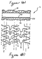
- Figures 6(a) and 6(b) show a further embodiment of the invention and illustrate how the shape of the wall of a continuous tubular blank corresponds to the stent of this invention.
- Figure 6(a) shows a longitudinal cross-section of a portion of a tubular blank having a constant inner diameter but varying outer diameter. This blank is then used to form the sinusoidal segments and bridges of the stent.
- Figure 6(b) shows that the regions of the bridges adjoining the sinusoidal shaped segments (i.e., at the zero point) may be made with a smaller thickness than the remaining portions of the stent.
- This stent comprises bridge elements 78 adjoining sinusoidal shaped segments 72 at zero points 71 of the sinusoidal shape.
- the bridge elements are evenly spaced.
- the bridge elements are spaced apart 720° along the sinusoidal shape of the segments.
- the apices of each bridge element face the same direction.
- the stent of Figure 4 illustrates cells all having the same shape and size. In contrast to Figures 1 and 2, this stent has fewer connecting bridges and fewer cells.
- the stent of Figure 8 is a hybrid of Figures 1 and 6.
- Bridge elements 88 adjoin adjacent segments 82 at zero points 81 of the sinusoidal shape. All bridge elements are oriented similarly (i.e., face the same direction). The bridge elements adjoining adjacent segments are evenly spaced. However, the number and spacing of bridge elements is not the same for each pair of adjacent segments. This results in cells of unequal size and may produce regions of variable flexibility as well as strength.
- An advantage to having a greater number of bridge elements (and hence cells) at either end of the stent is that they provide additional stability and strength to the ends of the stent while having fewer cells in the middle portion of the stent provides additional flexibility.
- FIG. 9 Another variation of the stent is illustrated in Figure 9.
- the bridge elements are evenly spaced throughout the stent, forming cells all of equal size and shape.
- apices for example, 90a and 90b
- apices face opposite directions in adjacent pairs of segments 92.
- Figure 10 illustrates yet another variation of the stent, wherein U-shaped portions 100a and 100b of bridge elements 108a and 108b, respectively, are facing in opposite directions in adjacent pairs of segments 102 and wherein the cells formed at each end of the stent are of different size than those of the remaining cells.
- the bridge elements adjoining any pair of adjacent segments are evenly spaced, but the number and spacing of bridge elements is not the same for each pair of adjacent segments. This results in cells of unequal size, and, in similar fashion to Figure 8, produces regions of greater strength at either end of the stent.
- the stent cell structure is sufficiently open to permit access to the lumen. For example, it is possible to manipulate catheters through the stent wall into vessel bifurcations in order to treat those vessels.
- the stent geometry provides a smooth profile for delivery when in the contracted position.
- the U-shape of the connecting bridges lies between a converging valley and peak of adjacent sinusoidal segments and acts as a bridge therebetween.
- peaks or valleys of some prior art stents protrude especially when the stent is bent during delivery. This protruding peak or valley can snag on a vessel wall or plaque, making delivery and positioning of the stent difficult.
- a further advantage is provided by the configuration of the bridge elements.
- the connector arms and U-shaped portion of the bridge elements act in cooperation with the segments to provide an effective support surface for the vessel wall while at the same time minimizing the amount of stent material which must be used.
- the most widely used method is to use a balloon catheter, disposing the stent about the balloon of the catheter in the contracted condition and then expanding the balloon once the stent has been delivered to the deployment site.
- Different solutions are also possible, such as using superelastic materials that expand when the stent reaches the implantation site. Typically these materials are held in a contracted condition by means of a containment element that is released when the stent has reached the desired location and position.
- Materials having a "shape memory" that expand from a first configuration to a second expanded configuration when heated to a transition temperature (i.e., body temperature) also may be used in order to achieve the radial expansion in the implant position.
- the stent is made from a metal capable of satisfying two fundamental requirements: the ability to deform during the expansion phase and the ability to resist forces which could lead to contraction of the stent. That is, the stent retains the expanded shape.
- the stents of this invention may comprise 316 stainless steel or a shape memory material known under the commercial designation "Nitinol". "Nitinol” is a nickel-titanium alloy that has been shown to be successful due to its superelasticity as well as its shape memory. Stents also may comprise biodegradable and/or biocompatible polymers, as known to one of skill in the art.
- the stent of this invention comprises a tubular body with an apertured wall.
- Methods of making the stent include, i.a.:
- the first arrangement described is the one currently preferred for producing stents of this invention.
- the use of laser beams to cut a continuous tubular blank has been shown to be the most flexible way to modify rapidly the characteristics of the stent during production.
- Such methods may be used to produce a stent having a variable wall thickness, and, in either case, with wall material having different cross-sections. These methods include making the stent from a continuous tubular blank and machining, grinding, chemically etching, or electron discharge machining the tube to produce the desired pattern and also obtain sections of desired cross-section. Alternatively, a tubular blank having variable thickness down its length could be laser cut to form the desired arrangement of segments and bridges. A stent could be formed and then the inside surface could be turned or micro-etched.
- the production method is not critical to the stents of this invention, as they may be formed by any desired method. This applies to the choice of the individual techniques and the order in which the various operations (the production of the apertured parts, segmentation, possible folding of the strip-like element, etc.) are performed.
Abstract
Description
- The present invention relates to stents for angioplasty. In particular, the invention relates to a stent having a cellular design.
- The term "stent" is intended to indicate devices useful for endoluminal insertion (for example, in a blood vessel), usually effected by means of catheterization, with subsequent deployment in place so as to achieve local support of the lumen. The primary purpose of the stent is to eliminate and avoid the restenosis (i.e., narrowing or closure) of the treated area.
- For a general review of vascular stents, reference is made to "Textbook of Interventional Cardiology" edited by Eric J Topol, W.B. Saunders Company, 1994 and, in particular, to section IV of volume II, entitled "Coronary Stenting".
- Many patents also provide a general review of stents, for example, U.S. Patent Nos. 4,503,569; 4,768,507; 4,776,337; 4,800,882; 4,830,003; 4,856,516; 4,886,062; 4,907,336; and EP 0 201 466A.
- Notwithstanding the extensive research and experimentation in the stent field, as documented in the patent literature, only a relatively small number of operative solutions have, until now, found practical application. This is due to various factors, which include the following problems or requirements:
- while moving toward the treatment site, the stent should be capable of adapting to the path, which may include various curved sections;
- distortion of the stent while it is being positioned should not be detrimental to the ability of the stent to provide an effective support when it is positioned and deployed;
- the longitudinal shortening effect which occurs in many stents upon deployment should be limited, if not avoided;
- maximum homogeneity and uniformity in the expansion of the stent should be achieved at the desired location;
- an extensive support surface should be provided to the wall of the lumen which is being supported;
- the origination of complex shapes and/or possible stagnation sites, especially in blood vessels, should be avoided, in order to avoid undesirable phenomena such as coagulation or thrombosis; and
- the stents should be able to be simply and reliably produced using available technology and they should incorporate the requirements listed above.
-
- A stent is subject to various forces, including compression, flexure, and torsion. These stresses often cause the stent to perform in an undesirable manner. Additionally, a significant disadvantage of current stent designs is their failure to distribute these stresses throughout the structure of the stent. Each of these stresses is maximized in a particular area of the stent. In current stent designs two or more of these areas of maximum stress overlap. This results in at least two problems. First, an overlap of the maximum stress areas may overly fatigue the stent and cause failure in an area of overlapped maximum stress. Second, the failure to distribute or discharge the maximum stress of these forces at different areas causes stress concentration on the vessel wall which may cause vessel wall injury. Thus what is needed in the art is a stent meeting the requirements listed above that will avoid stress concentration and elastic distortion as well as provide good elastic matching between the stent and the vessel into which it is placed.
- This invention is primarily a method of making a stent having the features set forth in the annexed claims. The invention also relates to the respective stent.
- The invention will now be described, by way of example only, with reference to the accompanying drawings.
- Figure 1 is a plan view showing the geometry of a tubular stent adapted to be manufactured according to the present invention, the stent being cut longitudinally and opened to lie within a single plane, the stent being in a radially contracted configuration.
- Figure 2 illustrates the stent of Figure 1 in its radially expanded configuration.
- Figure 3(a) illustrates an expanded view of a single cell within the wall of the stent of Figure 2 and Figures 3(b), 3(c), 3(d), 3(c) and 3(f) show the cross-sectional areas of portions of the stent.
- Figures 4(a) to 4(f) illustrate the effects of compression, flexure, and torsion, respectively, on a cell of the stent of this invention.
- Figures 5(a) to 5(f) illustrate various shapes of the wall of a continuous tubular blank used to make the stent of this invention.
- Figures 6(a) and 6(b) illustrate the variation in cross section of a section of the stent of this invention.
- Figure 7 is a view similar to Figure 1 of another embodiment of the stent of this invention.
- Figure 8 is a view similar to Figure 1 of another embodiment of the stent of this invention.
- Figure 9 is a view similar to Figure 1 of another embodiment of the stent of this invention.
- Figure 10 is a view similar to Figure 1 of another embodiment of the stent of this invention.
-
- A stent is inserted into a lumen, such as a blood vessel, at a site where stenosis, i.e., narrowing or stricture, is to be corrected. The stent is a tubular envelope, tubular body, or cylinder having apertured walls, such as, for example, a mesh-like structure. The stent typically has dimensions between several millimeters and several tens of millimeters in length, and a wall thickness of the order of, for example, several hundredths of millimeters. The stent is normally positioned in situ by catheterization through the vasculature followed by radial expansion from an introduction diameter of, for example, about 1.0 to 1.5 mm, to an expanded diameter of, for example, about 3 to 4 mm. In this expanded condition, the stent exerts a supporting force on the lumen, thereby avoiding or at least slowing restenosis of the vessel. In general, the external diameter of the stent in the radially-contracted condition is chosen to enable the introduction of the stent into a lumen, while the expanded diameter corresponds to the diameter required to be maintained in the lumen once the stenosis has been eliminated. It should also be remembered that, although the principle application of the stent described is in relation to the treatment of blood vessels, it may also be useful as a support element for any lumen present in the human or animal body.
- The stent of this invention is a tubular body, i.e., a cylinder, with an open, or apertured, mesh-like structure. The stent is capable of being dilated from a radially-contracted position to a radially-expanded position. The tubular body is comprised of a wall having an inner surface and an outer surface defining a radial stent thickness therebetween. In one embodiment, the material making up the mesh-like structure of the stent varies in its cross-sectional shape and/or cross-sectional area. It has been discovered that this cross-sectional variation (and thus a variation in thickness and/or width in the stent wall) produces a particularly desirable stent because the strength, flexibility, and support of the stent may be varied in localized areas. In areas requiring flexibility, the width as measured along the circumference of the tubular body and/or the radial thickness are made smaller to enhance flexibility. In areas requiring strength, the width and/or thickness are made larger. In areas not requiring flexibility, the width is increased to provide added vascular support.
- In the embodiments illustrated in the Figures, the stent is shown in planar views so that the geometry of the stent may be seen easily. The body of the stent extends longitudinally in the direction identified as the Z axis. It also lies in the Z plane, i.e., a plane coincident with the Z axis. During delivery and use of the stent, the stent may be flexed, bent or folded; thus good flexibility is one of the required characteristics of the stent. Another important characteristic of both the design and the material of the stent includes strength, i.e., the ability to withstand stresses due to compression, flexure, and torsion, as discussed further below.
- Figure 1 illustrates a plan view of the stent of this invention. The body of
stent 1 is comprised of a plurality ofsuccessive segments 2 of generally annular form. Figure 1 shows a stent comprising eightannular segments 2. Typically, the length ofsegments 2 measured in the longitudinal direction (i.e., along the Z axis) may range up to several millimeters (mm) but preferably is approximately 2 mm. That is,segments 2 are fairly "short" in comparison to the total length of the stent. - The various segments of
stent 1 are joined together by bridge elements 8 (which are actually integral components of the stent wall) that connectadjacent segments 2 and enablestent 1 to flex or bend. - Radiopaque
marker 13 optionally is provided.Marker 13 is integral withsegments 2 and typically is located on the proximal and/or distal ends of the stent. "Proximal and distal ends" refers to the portion of the stent nearest and farthest, respectively, from the point of entry of the stent into the vasculature. Suitable radiopaque markers include metals such as platinum, tantalum, gold, and alloys of these metals. Such markers permit exact placement of a stent within the vasculature of a patient. During manufacture the radiopaque marker may be crimped into a hole in the stent wall. - The longitudinal flexibility of
stent 1, necessary to assist in its delivery and location at the implantation site, is essentially due tobridge elements 8, while its structural strength, that is, its support of the lumen, is due primarily to the structure ofsegments 2. The desired characteristics of the stent can be obtained by adapting the arrangement and relationship of the bridge elements and the segments. - Figure 1 shows a plan view of a stent which has been cut open and laid flat; that is, the stent is no longer in a tubular shape. Figure 1 illustrates that each
segment 2 has a serpentine or sinusoidal wave shape. Each segment comprises peaks 4 andvalleys 6. Each annular segment is a mirror image of an adjacent annular segment about a plane perpendicular to the longitudinal axis of the stent. Thus, the peaks of one segment are aligned longitudinally with valleys of an adjacent segment. For purposes of this description the term "sinusoidal wave shape" means that the annular segments have an undulating repeating pattern similar to that of a sine wave. It is not intended to mean that the shape is limited to that of a sine wave. -
Bridge elements 8 separate adjacent segments and maintain a distance between them in both the expanded and contracted conditions. Eachbridge element 8 comprises a concave portion, or U-shape 10, havingapex 12. The U-shape is adjoined to twoconnector arms 14 which extend from the U-shape and adjoin adjacent sinusoidal-shapedsegments 2 at a zero point of the sinusoidal wave shape of each segment. The point of connection is between a peak and a valley of each segment such that the apex of the U-shape extends in the direction of the converging peak and valley that is nearest the attachment of the connector arm. These arms extend away from the U-shape and curve back to join the segments in the direction of the apex of the U-shape. Preferably these arms form an angle α of about 90 degrees with the U-shape.Bridge elements 8 are relatively flexible and change shape only slightly from the contracted to the expanded condition, as can be seen in Figures 1 and 2.Arms 14 adjoin adjacent sinusoidal wave shaped segments between a peak and a valley and preferably at zero-point 11 of the sinusoidal shape. (On a sine curve plotted on an X and Y axis, the "zero-point" is that point that intersects the X axis.) - Figures 1 and 2 illustrate an embodiment of the stent of this invention wherein the connector arms of each bridge element adjoin alternate zero points of each adjacent segment. That is, in terms of the sinusoidal wave shape of each segment, bridge elements are connected at zero points separated by 360°. This results in even spacing of bridge elements between adjacent segments. In addition, the bridge elements are oriented in the same direction; that is, the U-shaped portion of each bridge element faces the same direction. It has been found that connection of the bridge elements at the zero points not only produces a very elastic joint but also results in the longitudinal length of the stent being the same in the contracted condition and the expanded condition and in all degrees of expansion therebetween.
- A radially-contracted condition of the stent is illustrated in Figure 1. This condition is slightly expanded from the stents fully contracted delivery condition so that the details of the stents structure may be more clearly shown. The radially-expanded condition of the stent shown in Figure 2. Figure 2 shows that a
segment 2 is elongated compared to the same segment in Figure 1. That is, the segments retain the sinusoidal shape, but the amplitude and the frequency of the sine wave is less in the expanded condition than in the contracted condition. Figures 1 and 2 also show that theconnector arms 14 remain substantially parallel to the longitudinal axis of the stent in both the radially contracted position (Figure 1) and radially expanded position (Figure 2). - An alternative way of describing the structure of the stents of this invention is in terms of its substantially tubular surface which includes multiple cells. Figure 3(a), is a view of one cell of the stent of Figure 2. Figures 1 and 2 illustrate that the stent is made up of individual, interconnected cells, each cell having the same size and shape. Figures 3(b) to 3(f) illustrate that the cross sectional shape and area of the material making up the stent varies over the cell. The perimeter of a cell is formed from portions of adjacent sinusoidal segments (2a and 2b) and two bridge elements (8a and 8b).
Sinusoidal segment portions 2a and 2b are 360° portions of the sinusoidal wave shape of the annular segments.Arms Apex 12a of bridge 8a is oriented in the same direction as apex 12b ofbridge 8b.Bridges 8a and 8b adjoinadjacent segments 2a and 2b at zero points 11 of the sinusoidal shape; that is, between the peaks and valleys of the segments.Bridge element 8b, having U-shape 10b, apex 12b, andarms - Figures 3(b), 3(c), 3(d), 3(e) and 3(f) show the shape and size of the cross-section of different portions of the cell taken along lines b-b, c-c, d-d, e-e and f-f respectively. It is preferred that the cross-sectional area of the material making up the stent vary. The cross-sectional shape may vary as well. An alternate way of describing this is that the width of the material making up the stent of Figures 1 and 2 (i.e., the width of any portion of a bridge or a sinusoidal segment in plane Z) may be different than the thickness of that portion (i.e., the dimension in a plane X, perpendicular to plane Z). It has been found that varying the cross-sectional area of different portions of the material of the stent produces optimum strength, flexibility, and support, enabling the stent to accommodate the differing stresses it encounters during use.
- Through the use of stress analysis of the stent, it has been determined that during use, different areas of the cells are stressed, depending upon the forces acting on the stent. For example, when the stent is under compression, stress is maximized in the peaks and valleys of the sinusoidal segments. When the stent is flexed, the stress is maximized around the apex of the U-shape of the bridge elements. Under torsion, the stress is maximized at the ends of the connector arms of the bridge elements, i.e., where a bridge element connects to a sinusoidal segment.
- Figures 4(a) to 4(f) illustrate the effects of compression, flexure, and torsion, respectively, on one cell of the stent of this invention. The arrows indicate the direction of the forces applied to the stent. The areas of the stent cell having the greatest stress concentration are indicated by solid lines. In Figure 4(a), the stent is subjected to a compression force. Figure 4(b) shows that the areas of greatest stress occurs at the peaks and valleys of the sinusoidal shaped segments. Figure 4(c) shows s stent undergoing flexure. Figure 4(d) indicates that the areas of greatest stress occur at the apex of the U-shape of the bridge. Figure 4(e) shows a stent under torsion. Figure 4(f) indicates that the maximum stress occurs at the areas where the bridge joins the sinusoidal shaped segments, i.e., at the zero point.
- It is an advantage of the cellular design of the stent of this invention that the areas of maximum stress induced by compression, flexure and torsion forces do not overlap. This reduces the risk that a particular area of the stent cell structure will be overly fatigued and fail. It also reduces the risk of causing damage to the vessel wall which can result if there is a significant stress concentration at any portion of the cellular structure. In the stent of this invention maximum stresses from compression, flexure and torsion are distributed and discharged over three separate areas of the cellular structure thus reducing the risk of stent failure and damage to vessel walls.
- It is possible to alter the thickness and width of various portions of the stent during the manufacturing process. One way to do this is to form the desired wall geometry in a continuous tubular blank and then cut or machine the stent from this blank. For example, techniques such as laser incision, photo-incision, and electroerosion may be used to form a desired geometry. In this way, the stent bridges and sinusoidal segments are formed.
- Figure 5a shows a continuous tubular blank from which stents can be formed. The tubular blank has
outer surface 51 forming the outer diameter andinner surface 53 forming the inner diameter; surfaces 51 and 53 are separated bywall thickness 55. The characteristics of the stent including wall thickness and shape can be varied in accordance with the shape and surface configuration of inner andouter surfaces - Figures 6(a) and 6(b) show a further embodiment of the invention and illustrate how the shape of the wall of a continuous tubular blank corresponds to the stent of this invention. Figure 6(a) shows a longitudinal cross-section of a portion of a tubular blank having a constant inner diameter but varying outer diameter. This blank is then used to form the sinusoidal segments and bridges of the stent. Figure 6(b) shows that the regions of the bridges adjoining the sinusoidal shaped segments (i.e., at the zero point) may be made with a smaller thickness than the remaining portions of the stent.
- Turning now to Figure 7, various alternative embodiments of the stent of this invention are illustrated. This stent comprises
bridge elements 78 adjoining sinusoidal shapedsegments 72 at zero points 71 of the sinusoidal shape. The bridge elements are evenly spaced. In this case the bridge elements are spaced apart 720° along the sinusoidal shape of the segments. The apices of each bridge element face the same direction. As described above, when viewed as a cellular structure, the stent of Figure 4 illustrates cells all having the same shape and size. In contrast to Figures 1 and 2, this stent has fewer connecting bridges and fewer cells. - The stent of Figure 8 is a hybrid of Figures 1 and 6.
Bridge elements 88 adjoinadjacent segments 82 at zeropoints 81 of the sinusoidal shape. All bridge elements are oriented similarly (i.e., face the same direction). The bridge elements adjoining adjacent segments are evenly spaced. However, the number and spacing of bridge elements is not the same for each pair of adjacent segments. This results in cells of unequal size and may produce regions of variable flexibility as well as strength. An advantage to having a greater number of bridge elements (and hence cells) at either end of the stent is that they provide additional stability and strength to the ends of the stent while having fewer cells in the middle portion of the stent provides additional flexibility. - Another variation of the stent is illustrated in Figure 9. The bridge elements are evenly spaced throughout the stent, forming cells all of equal size and shape. However, apices (for example, 90a and 90b) of bridge elements 98 face opposite directions in adjacent pairs of segments 92.
- Figure 10 illustrates yet another variation of the stent, wherein U-shaped portions 100a and 100b of
bridge elements 108a and 108b, respectively, are facing in opposite directions in adjacent pairs ofsegments 102 and wherein the cells formed at each end of the stent are of different size than those of the remaining cells. The bridge elements adjoining any pair of adjacent segments are evenly spaced, but the number and spacing of bridge elements is not the same for each pair of adjacent segments. This results in cells of unequal size, and, in similar fashion to Figure 8, produces regions of greater strength at either end of the stent. - It is generally preferable to align the bridge elements between adjacent sinusoidal segments with the apices pointing in the direction of a converging peak and valley of the adjacent segments. This configuration provides a number of advantages. One advantage is that, in the expanded configuration, the stent cell structure is sufficiently open to permit access to the lumen. For example, it is possible to manipulate catheters through the stent wall into vessel bifurcations in order to treat those vessels. Another advantage is that the stent geometry provides a smooth profile for delivery when in the contracted position. In the stent design of this invention, the U-shape of the connecting bridges lies between a converging valley and peak of adjacent sinusoidal segments and acts as a bridge therebetween. This reduces the chance of snagging any cellular matter from the inside of the lumen. The peaks or valleys of some prior art stents protrude especially when the stent is bent during delivery. This protruding peak or valley can snag on a vessel wall or plaque, making delivery and positioning of the stent difficult. A further advantage is provided by the configuration of the bridge elements. The connector arms and U-shaped portion of the bridge elements act in cooperation with the segments to provide an effective support surface for the vessel wall while at the same time minimizing the amount of stent material which must be used.
- As to deployment (that is, the in situ expansion) of the stent, currently the most widely used method is to use a balloon catheter, disposing the stent about the balloon of the catheter in the contracted condition and then expanding the balloon once the stent has been delivered to the deployment site. Different solutions are also possible, such as using superelastic materials that expand when the stent reaches the implantation site. Typically these materials are held in a contracted condition by means of a containment element that is released when the stent has reached the desired location and position. Materials having a "shape memory" that expand from a first configuration to a second expanded configuration when heated to a transition temperature (i.e., body temperature) also may be used in order to achieve the radial expansion in the implant position.
- Usually the stent is made from a metal capable of satisfying two fundamental requirements: the ability to deform during the expansion phase and the ability to resist forces which could lead to contraction of the stent. That is, the stent retains the expanded shape. For example, the stents of this invention may comprise 316 stainless steel or a shape memory material known under the commercial designation "Nitinol". "Nitinol" is a nickel-titanium alloy that has been shown to be successful due to its superelasticity as well as its shape memory. Stents also may comprise biodegradable and/or biocompatible polymers, as known to one of skill in the art.
- These technological aspects will not be dealt with in detail in the present description in that they are not in themselves relevant to the comprehension and production of the invention. This also applies essentially to the technology for the production of the stent according to the invention. As described above, the stent of this invention comprises a tubular body with an apertured wall. Methods of making the stent include, i.a.:
- forming the stent from a continuous tubular blank intended to be segmented into individual stents, with the apertured parts being formed using techniques such as laser incision, photo-incision, electroerosion, and the like; and
- forming the stent from a strip-like body in which the apertured zones are formed, for example, using the techniques listed above, with the subsequent closure of the strip-like element into a tube.
-
- The first arrangement described is the one currently preferred for producing stents of this invention. In particular, the use of laser beams to cut a continuous tubular blank has been shown to be the most flexible way to modify rapidly the characteristics of the stent during production.
- Such methods may be used to produce a stent having a variable wall thickness, and, in either case, with wall material having different cross-sections. These methods include making the stent from a continuous tubular blank and machining, grinding, chemically etching, or electron discharge machining the tube to produce the desired pattern and also obtain sections of desired cross-section. Alternatively, a tubular blank having variable thickness down its length could be laser cut to form the desired arrangement of segments and bridges. A stent could be formed and then the inside surface could be turned or micro-etched.
- The production method is not critical to the stents of this invention, as they may be formed by any desired method. This applies to the choice of the individual techniques and the order in which the various operations (the production of the apertured parts, segmentation, possible folding of the strip-like element, etc.) are performed.
- Although particular embodiments have been disclosed herein in detail, this has been done for purposes of illustration only, and is not intended to be limiting with respect to the scope of the appended claims, which follow. In particular, it is contemplated by the inventor that various substitutions, alterations, and modifications may be made to the invention without departing from the spirit and scope of the invention as defined by the claims. For example, the frequency, number, and location of bridge elements and sinusoidal segments may be varied as necessary to obtain the desired characteristics of the stent.
Claims (14)
- A method of making a stent (1) comprising:providing a tubular blank defining a longitudinal axis (3); andforming the blank into first and second adjacent annular segments (2) connected by a plurality of bridge elements (8), each segment (2) defining a substantially sinusoidal shape having a plurality of peaks and valleys, the peaks of the first segment extending toward the second segment and being aligned longitudinally with the valleys of the second segment, the plurality of bridge elements (8) having a U-shaped portion (10) between first and second connector arms (14), the first connector arm of one bridge element (8) being connected between a first peak and a first valley of the first segment and the second connector arm being connected between a first peak and a first valley of the second segment in a manner such that the U-shaped portion (10) extends in the direction of the first peak of the first segment and the first valley of the second segment, wherein said tubular blank includes opposed surfaces (51, 53) separated by a non-uniform wall thickness (55) providing different thicknesses at different portions of the stent.
- The method of claim 1, wherein the regions of said bridge elements (8) adjoining the sinusoidal shaped elements (2) are made with a smaller thickness that the remaining portions of the stent.
- The method of any of claims 1 or 2, wherein in said tubular blank said opposed surfaces (51, 53) define outer (51) and inner (53) surfaces having respective inner and outer diameters, both said respective inner and outer diameters being variable to provide said non-uniform wall thickness.
- The method of any of claims 1 or 2, wherein in said tubular blank said opposed surfaces (51, 53) define outer (51) and inner (53) surfaces having respective inner and outer diameters, said inner diameter being constant and said outer diameter varying to provide said non-uniform wall thickness.
- The method of any of claims 1 or 2, wherein in said tubular blank said opposed surfaces (51, 53) define outer (51) and inner (53) surfaces having respective inner and outer diameters, said outer diameter being constant and said inner diameter varying to provide said non-uniform wall thickness.
- The method of any of claims 1 to 5, wherein said tubular blank is provided as a continuous tubular blank subsequently apertured to form said segments (2) and bridge elements (8).
- The method of any of claims 1 to 5, wherein said tubular blank is formed a strip-like body apertured to form said segments (2) and bridge elements (8), with the subsequent closure of the strip-like body into a tube.
- The method of any of claims 1 to 7, wherein the forming step is by a method selected from one of laser incision, photo-incision, and electroerosion.
- The method of claim 1 wherein the U-shaped portions (10) of the plurality of bridge elements are oriented in the same direction.
- The method of claim 1 further comprising a third annular segment (2) connected to the second annular segment (2) by a plurality of bridge elements (8), wherein the U-shaped portion (10) of the plurality of bridge elements (8) is oriented in one direction between the first and second annular segments (2) and in the opposite direction between the second and third annular segments (2).
- The method of claim 1 wherein the connector arm (14) of the bridge element (8) joins the annular segment (12) at a zero point of the sinusoidal shape.
- The method of claim 11 wherein each connector arm (14) joins each annular segment (2) at a zero point of the sinusoidal shape.
- The method of claim 1 further comprising a third annular segment (2) connected by bridge elements to the second annular segment (2), wherein the bridge elements (8) join zero points separated by 360° between the first and second adjacent segments (2), and further wherein the bridge elements (8) join zero points separated by 720° between the second and third adjacent segments.
- A stent manufactured with the method of any of claims 1 to 13.
Applications Claiming Priority (2)
| Application Number | Priority Date | Filing Date | Title |
|---|---|---|---|
| US410303 | 1999-10-01 | ||
| US09/410,303 US6451049B2 (en) | 1998-04-29 | 1999-10-01 | Stents for angioplasty |
Publications (2)
| Publication Number | Publication Date |
|---|---|
| EP1088528A1 true EP1088528A1 (en) | 2001-04-04 |
| EP1088528B1 EP1088528B1 (en) | 2006-10-25 |
Family
ID=23624143
Family Applications (1)
| Application Number | Title | Priority Date | Filing Date |
|---|---|---|---|
| EP00120834A Expired - Lifetime EP1088528B1 (en) | 1999-10-01 | 2000-09-25 | Stents for angioplasty |
Country Status (6)
| Country | Link |
|---|---|
| US (2) | US6451049B2 (en) |
| EP (1) | EP1088528B1 (en) |
| AT (1) | ATE343355T1 (en) |
| DE (1) | DE60031490T2 (en) |
| DK (1) | DK1088528T3 (en) |
| ES (1) | ES2274758T3 (en) |
Cited By (26)
| Publication number | Priority date | Publication date | Assignee | Title |
|---|---|---|---|---|
| EP1159934A2 (en) * | 2000-06-01 | 2001-12-05 | Terumo Kabushiki Kaisha | Implantable tubular device (stent) |
| WO2002100298A1 (en) * | 2001-06-11 | 2002-12-19 | Advanced Cardiovascular Systems, Inc. | Intravascular stent |
| EP1277449A1 (en) | 2001-07-20 | 2003-01-22 | SORIN BIOMEDICA CARDIO S.p.A. | Stent |
| EP1310242A1 (en) | 2001-11-13 | 2003-05-14 | SORIN BIOMEDICA CARDIO S.p.A. | Carrier and kit for endoluminal delivery of active principles |
| EP1348402A1 (en) * | 2002-03-29 | 2003-10-01 | Advanced Laser Applications Holding S.A. | Intraluminal endoprosthesis, radially expandable, perforated for drug delivery |
| US6656220B1 (en) | 2002-06-17 | 2003-12-02 | Advanced Cardiovascular Systems, Inc. | Intravascular stent |
| WO2002024111A3 (en) * | 2000-09-22 | 2003-12-24 | Cordis Corp | Stent with optimal strength and radio-opacity characteristics |
| EP1424960A2 (en) * | 2001-07-26 | 2004-06-09 | Alveolus, Inc. | Removable stent and method of using the same |
| WO2004047683A2 (en) * | 2002-11-22 | 2004-06-10 | Medtronic Vascular, Inc. | Stent having tapered edges |
| WO2004078072A1 (en) * | 2003-03-03 | 2004-09-16 | Medtronic Vascular, Inc. | Method for manufacturing an endovascular support device |
| DE10352874A1 (en) * | 2003-11-10 | 2005-06-16 | Qualimed Innovative Medizinprodukte Gmbh | stent |
| EP1558178A2 (en) * | 2002-11-05 | 2005-08-03 | Alveolus, Inc. | Stent with geometry determinated functionality and method of making the same |
| EP1561436A1 (en) | 2004-02-05 | 2005-08-10 | SORIN BIOMEDICA CARDIO S.r.l. | A stent for endoluminal delivery of active principles or agents |
| WO2005104990A1 (en) * | 2004-05-03 | 2005-11-10 | Qualimed Innovative Medizinprodukte Gmbh | Stent |
| WO2005115277A2 (en) | 2004-05-21 | 2005-12-08 | Conor Medsystems, Inc. | Stent with contoured bridging elements |
| EP1932496A1 (en) * | 2005-10-06 | 2008-06-18 | Kaneka Corporation | Stent to be placed in the living body |
| EP2253339A1 (en) | 2003-02-21 | 2010-11-24 | Sorin Biomedica Cardio S.r.l. | A process for producing stents and corresponding stent |
| US7946019B2 (en) | 1996-12-30 | 2011-05-24 | Sorin Biomedica Cardio S.R.L. | Process for producing a stent for angioplasty |
| US8206436B2 (en) | 2002-11-05 | 2012-06-26 | Merit Medical Systems, Inc. | Coated stent with geometry determinated functionality and method of making the same |
| US8257426B2 (en) | 2001-06-11 | 2012-09-04 | Advanced Cardiovascular Systems, Inc. | Intravascular stent with a plurality of first and second peaks |
| EP2559409A3 (en) * | 2004-01-14 | 2013-11-27 | Medinol Ltd. | Longitudinally flexible stent |
| US8778009B2 (en) | 2006-10-06 | 2014-07-15 | Abbott Cardiovascular Systems Inc. | Intravascular stent |
| CN104490501A (en) * | 2014-12-25 | 2015-04-08 | 周玉杰 | Gradual changed thickness coronary stent suitable for coronary artery tortuosity angulation lesion |
| US9968471B1 (en) | 2000-03-01 | 2018-05-15 | Medinol Ltd. | Longitudinally flexible stent |
| WO2019173698A1 (en) * | 2018-03-09 | 2019-09-12 | Vesper Medical, Inc. | Implantable stent |
| IT201900003579A1 (en) | 2019-03-12 | 2020-09-12 | Alvimedica Tibbi Ueruenler Sanayi Ve Dis Ticaret A S | STENT FOR CORONARY OSTIUM |
Families Citing this family (117)
| Publication number | Priority date | Publication date | Assignee | Title |
|---|---|---|---|---|
| US7204848B1 (en) | 1995-03-01 | 2007-04-17 | Boston Scientific Scimed, Inc. | Longitudinally flexible expandable stent |
| JP4636634B2 (en) | 1996-04-26 | 2011-02-23 | ボストン サイエンティフィック サイムド,インコーポレイテッド | Intravascular stent |
| US20040106985A1 (en) | 1996-04-26 | 2004-06-03 | Jang G. David | Intravascular stent |
| US6235053B1 (en) | 1998-02-02 | 2001-05-22 | G. David Jang | Tubular stent consists of chevron-shape expansion struts and contralaterally attached diagonal connectors |
| US5807404A (en) * | 1996-09-19 | 1998-09-15 | Medinol Ltd. | Stent with variable features to optimize support and method of making such stent |
| US20060173531A1 (en) * | 1996-09-19 | 2006-08-03 | Jacob Richter | Stent with variable features to optimize support and method of making such stent |
| US6451049B2 (en) * | 1998-04-29 | 2002-09-17 | Sorin Biomedica Cardio, S.P.A. | Stents for angioplasty |
| IT1292295B1 (en) * | 1997-04-29 | 1999-01-29 | Sorin Biomedica Cardio Spa | ANGIOPLASTIC STENT |
| US6309414B1 (en) * | 1997-11-04 | 2001-10-30 | Sorin Biomedica Cardio S.P.A. | Angioplasty stents |
| DK174814B1 (en) * | 1998-02-25 | 2003-12-01 | Cook William Europ | stent device |
| US6558415B2 (en) * | 1998-03-27 | 2003-05-06 | Intratherapeutics, Inc. | Stent |
| US6261319B1 (en) * | 1998-07-08 | 2001-07-17 | Scimed Life Systems, Inc. | Stent |
| US6682554B2 (en) | 1998-09-05 | 2004-01-27 | Jomed Gmbh | Methods and apparatus for a stent having an expandable web structure |
| US6755856B2 (en) | 1998-09-05 | 2004-06-29 | Abbott Laboratories Vascular Enterprises Limited | Methods and apparatus for stenting comprising enhanced embolic protection, coupled with improved protection against restenosis and thrombus formation |
| US7815763B2 (en) * | 2001-09-28 | 2010-10-19 | Abbott Laboratories Vascular Enterprises Limited | Porous membranes for medical implants and methods of manufacture |
| US7887578B2 (en) | 1998-09-05 | 2011-02-15 | Abbott Laboratories Vascular Enterprises Limited | Stent having an expandable web structure |
| US6193744B1 (en) * | 1998-09-10 | 2001-02-27 | Scimed Life Systems, Inc. | Stent configurations |
| US7226475B2 (en) | 1999-11-09 | 2007-06-05 | Boston Scientific Scimed, Inc. | Stent with variable properties |
| EP1132058A1 (en) * | 2000-03-06 | 2001-09-12 | Advanced Laser Applications Holding S.A. | Intravascular prothesis |
| US6616689B1 (en) | 2000-05-03 | 2003-09-09 | Advanced Cardiovascular Systems, Inc. | Intravascular stent |
| CN2430175Y (en) * | 2000-05-15 | 2001-05-16 | 臧式先 | Medical tubular rack |
| AU2001282959A1 (en) * | 2000-07-24 | 2002-02-05 | Jeffrey Grayzel | Stiffened balloon catheter for dilatation and stenting |
| US7766956B2 (en) | 2000-09-22 | 2010-08-03 | Boston Scientific Scimed, Inc. | Intravascular stent and assembly |
| US20010044650A1 (en) * | 2001-01-12 | 2001-11-22 | Simso Eric J. | Stent for in-stent restenosis |
| EP1363561B1 (en) * | 2001-01-15 | 2009-11-25 | Terumo Kabushiki Kaisha | Stent |
| CN1289160C (en) * | 2001-02-01 | 2006-12-13 | 钟渊化学工业株式会社 | Stent |
| US6740114B2 (en) * | 2001-03-01 | 2004-05-25 | Cordis Corporation | Flexible stent |
| US6824560B2 (en) * | 2001-06-13 | 2004-11-30 | Advanced Cardiovascular Systems, Inc. | Double-butted superelastic nitinol tubing |
| US20030077310A1 (en) | 2001-10-22 | 2003-04-24 | Chandrashekhar Pathak | Stent coatings containing HMG-CoA reductase inhibitors |
| DE10233085B4 (en) | 2002-07-19 | 2014-02-20 | Dendron Gmbh | Stent with guide wire |
| US8425549B2 (en) | 2002-07-23 | 2013-04-23 | Reverse Medical Corporation | Systems and methods for removing obstructive matter from body lumens and treating vascular defects |
| US6878162B2 (en) * | 2002-08-30 | 2005-04-12 | Edwards Lifesciences Ag | Helical stent having improved flexibility and expandability |
| US9561123B2 (en) | 2002-08-30 | 2017-02-07 | C.R. Bard, Inc. | Highly flexible stent and method of manufacture |
| US20040054398A1 (en) * | 2002-09-13 | 2004-03-18 | Cully Edward H. | Stent device with multiple helix construction |
| US20040093056A1 (en) | 2002-10-26 | 2004-05-13 | Johnson Lianw M. | Medical appliance delivery apparatus and method of use |
| US7875068B2 (en) | 2002-11-05 | 2011-01-25 | Merit Medical Systems, Inc. | Removable biliary stent |
| US7959671B2 (en) | 2002-11-05 | 2011-06-14 | Merit Medical Systems, Inc. | Differential covering and coating methods |
| US6923829B2 (en) | 2002-11-25 | 2005-08-02 | Advanced Bio Prosthetic Surfaces, Ltd. | Implantable expandable medical devices having regions of differential mechanical properties and methods of making same |
| US20070239251A1 (en) * | 2002-12-31 | 2007-10-11 | Abbott Cardiovascular Systems Inc. | Flexible stent |
| US7179286B2 (en) * | 2003-02-21 | 2007-02-20 | Boston Scientific Scimed, Inc. | Stent with stepped connectors |
| AU2004224415B2 (en) | 2003-03-19 | 2011-07-14 | Vactronix Scientific, Llc | Endoluminal stent having mid-interconnecting members |
| US7637934B2 (en) | 2003-03-31 | 2009-12-29 | Merit Medical Systems, Inc. | Medical appliance optical delivery and deployment apparatus and method |
| US7604660B2 (en) | 2003-05-01 | 2009-10-20 | Merit Medical Systems, Inc. | Bifurcated medical appliance delivery apparatus and method |
| US7789979B2 (en) * | 2003-05-02 | 2010-09-07 | Gore Enterprise Holdings, Inc. | Shape memory alloy articles with improved fatigue performance and methods therefor |
| US20050060025A1 (en) * | 2003-09-12 | 2005-03-17 | Mackiewicz David A. | Radiopaque markers for medical devices |
| US20050080479A1 (en) * | 2003-09-29 | 2005-04-14 | Feng James Q. | Expandable endovascular stent |
| CA2540372A1 (en) * | 2003-09-30 | 2005-04-14 | Alveolus Inc | Removable stent |
| US7479158B2 (en) * | 2004-02-20 | 2009-01-20 | Boston Scientific Scimed, Inc. | Stent with nested flexible connectors for flexibility and crimpability |
| US8430925B2 (en) | 2004-02-27 | 2013-04-30 | Cardiacmd, Inc. | Prosthetic heart valves, scaffolding structures, and systems and methods for implantation of same |
| DE102004012981B4 (en) * | 2004-03-16 | 2009-01-02 | Alveolus Inc. | stent |
| JP5007888B2 (en) * | 2004-05-05 | 2012-08-22 | インヴァテック エス.ピー.エイ. | Lumen prosthesis |
| US20060074480A1 (en) | 2004-09-01 | 2006-04-06 | Pst, Llc | Stent and method for manufacturing the stent |
| DE102004045226B4 (en) * | 2004-09-17 | 2008-01-17 | Optiray Medizintechnik Gmbh | support prosthesis |
| US7887579B2 (en) | 2004-09-29 | 2011-02-15 | Merit Medical Systems, Inc. | Active stent |
| US7731654B2 (en) | 2005-05-13 | 2010-06-08 | Merit Medical Systems, Inc. | Delivery device with viewing window and associated method |
| US8043366B2 (en) | 2005-09-08 | 2011-10-25 | Boston Scientific Scimed, Inc. | Overlapping stent |
| CA2948428C (en) * | 2006-02-14 | 2020-06-30 | Angiomed Gmbh & Co. Medizintechnik Kg | Highly flexible stent and method of manufacture |
| US20070191926A1 (en) * | 2006-02-14 | 2007-08-16 | Advanced Cardiovascular Systems, Inc. | Stent pattern for high stent retention |
| US8147541B2 (en) | 2006-02-27 | 2012-04-03 | Aortx, Inc. | Methods and devices for delivery of prosthetic heart valves and other prosthetics |
| US8403981B2 (en) | 2006-02-27 | 2013-03-26 | CardiacMC, Inc. | Methods and devices for delivery of prosthetic heart valves and other prosthetics |
| AU2007249229B2 (en) * | 2006-05-12 | 2013-05-23 | Cardinal Health 529, Llc | Balloon expandable bioabsorbable drug eluting flexible stent |
| GB0609841D0 (en) | 2006-05-17 | 2006-06-28 | Angiomed Ag | Bend-capable tubular prosthesis |
| US8585594B2 (en) | 2006-05-24 | 2013-11-19 | Phoenix Biomedical, Inc. | Methods of assessing inner surfaces of body lumens or organs |
| CN101506538A (en) | 2006-06-20 | 2009-08-12 | 奥尔特克斯公司 | Torque shaft and torque drive |
| US8500799B2 (en) | 2006-06-20 | 2013-08-06 | Cardiacmd, Inc. | Prosthetic heart valves, support structures and systems and methods for implanting same |
| CA2657446A1 (en) | 2006-06-21 | 2007-12-27 | Aortx, Inc. | Prosthetic valve implantation systems |
| US7988720B2 (en) | 2006-09-12 | 2011-08-02 | Boston Scientific Scimed, Inc. | Longitudinally flexible expandable stent |
| US20080269774A1 (en) | 2006-10-26 | 2008-10-30 | Chestnut Medical Technologies, Inc. | Intracorporeal Grasping Device |
| GB0622465D0 (en) * | 2006-11-10 | 2006-12-20 | Angiomed Ag | Stent |
| US9387100B2 (en) * | 2007-01-08 | 2016-07-12 | Cardinal Health Switzerland GmbH | Intraluminal medical device having variable axial flexibility about the circumference of the device |
| EP2120785B1 (en) | 2007-02-12 | 2021-12-01 | C.R. Bard, Inc. | Highly flexible stent and method of manufacture |
| US8333799B2 (en) * | 2007-02-12 | 2012-12-18 | C. R. Bard, Inc. | Highly flexible stent and method of manufacture |
| US8974514B2 (en) | 2007-03-13 | 2015-03-10 | Abbott Cardiovascular Systems Inc. | Intravascular stent with integrated link and ring strut |
| US8016874B2 (en) * | 2007-05-23 | 2011-09-13 | Abbott Laboratories Vascular Enterprises Limited | Flexible stent with elevated scaffolding properties |
| US8128679B2 (en) | 2007-05-23 | 2012-03-06 | Abbott Laboratories Vascular Enterprises Limited | Flexible stent with torque-absorbing connectors |
| US7867273B2 (en) * | 2007-06-27 | 2011-01-11 | Abbott Laboratories | Endoprostheses for peripheral arteries and other body vessels |
| US8226701B2 (en) | 2007-09-26 | 2012-07-24 | Trivascular, Inc. | Stent and delivery system for deployment thereof |
| US8663309B2 (en) | 2007-09-26 | 2014-03-04 | Trivascular, Inc. | Asymmetric stent apparatus and method |
| US8066755B2 (en) | 2007-09-26 | 2011-11-29 | Trivascular, Inc. | System and method of pivoted stent deployment |
| EP2194921B1 (en) | 2007-10-04 | 2018-08-29 | TriVascular, Inc. | Modular vascular graft for low profile percutaneous delivery |
| US9220522B2 (en) | 2007-10-17 | 2015-12-29 | Covidien Lp | Embolus removal systems with baskets |
| US8585713B2 (en) | 2007-10-17 | 2013-11-19 | Covidien Lp | Expandable tip assembly for thrombus management |
| US8926680B2 (en) * | 2007-11-12 | 2015-01-06 | Covidien Lp | Aneurysm neck bridging processes with revascularization systems methods and products thereby |
| US8066757B2 (en) | 2007-10-17 | 2011-11-29 | Mindframe, Inc. | Blood flow restoration and thrombus management methods |
| US8088140B2 (en) | 2008-05-19 | 2012-01-03 | Mindframe, Inc. | Blood flow restorative and embolus removal methods |
| US11337714B2 (en) | 2007-10-17 | 2022-05-24 | Covidien Lp | Restoring blood flow and clot removal during acute ischemic stroke |
| US9198687B2 (en) | 2007-10-17 | 2015-12-01 | Covidien Lp | Acute stroke revascularization/recanalization systems processes and products thereby |
| US10123803B2 (en) | 2007-10-17 | 2018-11-13 | Covidien Lp | Methods of managing neurovascular obstructions |
| US8083789B2 (en) | 2007-11-16 | 2011-12-27 | Trivascular, Inc. | Securement assembly and method for expandable endovascular device |
| US8328861B2 (en) | 2007-11-16 | 2012-12-11 | Trivascular, Inc. | Delivery system and method for bifurcated graft |
| US7850726B2 (en) | 2007-12-20 | 2010-12-14 | Abbott Laboratories Vascular Enterprises Limited | Endoprosthesis having struts linked by foot extensions |
| US8337544B2 (en) | 2007-12-20 | 2012-12-25 | Abbott Laboratories Vascular Enterprises Limited | Endoprosthesis having flexible connectors |
| US8920488B2 (en) | 2007-12-20 | 2014-12-30 | Abbott Laboratories Vascular Enterprises Limited | Endoprosthesis having a stable architecture |
| JP5457373B2 (en) | 2008-02-22 | 2014-04-02 | コヴィディエン リミテッド パートナーシップ | Device for blood flow recovery |
| WO2009126935A2 (en) | 2008-04-11 | 2009-10-15 | Mindframe, Inc. | Monorail neuro-microcatheter for delivery of medical devices to treat stroke, processes and products thereby |
| US8114149B2 (en) * | 2009-10-20 | 2012-02-14 | Svelte Medical Systems, Inc. | Hybrid stent with helical connectors |
| US8434906B2 (en) * | 2010-02-23 | 2013-05-07 | General Electric Company | Lighting system with thermal management system |
| US9039749B2 (en) | 2010-10-01 | 2015-05-26 | Covidien Lp | Methods and apparatuses for flow restoration and implanting members in the human body |
| GB2494632A (en) * | 2011-09-09 | 2013-03-20 | Isis Innovation | Stent and method of inserting a stent into a delivery catheter |
| DE102011057026B4 (en) * | 2011-12-23 | 2017-11-02 | Acandis Gmbh & Co. Kg | Medical device for insertion into a hollow body organ and manufacturing method |
| US8992595B2 (en) | 2012-04-04 | 2015-03-31 | Trivascular, Inc. | Durable stent graft with tapered struts and stable delivery methods and devices |
| US9498363B2 (en) | 2012-04-06 | 2016-11-22 | Trivascular, Inc. | Delivery catheter for endovascular device |
| WO2013187927A1 (en) * | 2012-06-15 | 2013-12-19 | Phraxis Inc. | Arterial and venous anchor devices forming an anastomotic connector and system for delivery |
| CN104869945A (en) * | 2012-10-22 | 2015-08-26 | 奥巴斯尼茨医学公司 | Medical device for implantation into luminal structures |
| US10271975B2 (en) * | 2013-03-15 | 2019-04-30 | Atrium Medical Corporation | Stent device having reduced foreshortening and recoil and method of making same |
| US10076399B2 (en) | 2013-09-13 | 2018-09-18 | Covidien Lp | Endovascular device engagement |
| US9980835B2 (en) | 2013-10-22 | 2018-05-29 | Orbusneich Medical Inc. | Medical device for implantation into luminal structures incorporating corrugated structural elements |
| JP6081948B2 (en) * | 2014-03-25 | 2017-02-15 | 株式会社World Medish Technology | Flexible stent |
| US10758381B2 (en) | 2016-03-31 | 2020-09-01 | Vesper Medical, Inc. | Intravascular implants |
| CN110234300B (en) | 2017-02-01 | 2021-04-06 | 学校法人加计学园冈山理科大学 | Bioabsorbable stent |
| US10238513B2 (en) | 2017-07-19 | 2019-03-26 | Abbott Cardiovascular Systems Inc. | Intravascular stent |
| US10849769B2 (en) | 2017-08-23 | 2020-12-01 | Vesper Medical, Inc. | Non-foreshortening stent |
| US11628076B2 (en) | 2017-09-08 | 2023-04-18 | Vesper Medical, Inc. | Hybrid stent |
| US10271977B2 (en) | 2017-09-08 | 2019-04-30 | Vesper Medical, Inc. | Hybrid stent |
| US11357650B2 (en) | 2019-02-28 | 2022-06-14 | Vesper Medical, Inc. | Hybrid stent |
| US11364134B2 (en) | 2018-02-15 | 2022-06-21 | Vesper Medical, Inc. | Tapering stent |
| CN117224297B (en) * | 2023-11-13 | 2024-02-13 | 太原理工大学 | Lower limb artery stent with reverse combined structure |
Citations (11)
| Publication number | Priority date | Publication date | Assignee | Title |
|---|---|---|---|---|
| US4503569A (en) | 1983-03-03 | 1985-03-12 | Dotter Charles T | Transluminally placed expandable graft prosthesis |
| US4768507A (en) | 1986-02-24 | 1988-09-06 | Medinnovations, Inc. | Intravascular stent and percutaneous insertion catheter system for the dilation of an arterial stenosis and the prevention of arterial restenosis |
| US4776337A (en) | 1985-11-07 | 1988-10-11 | Expandable Grafts Partnership | Expandable intraluminal graft, and method and apparatus for implanting an expandable intraluminal graft |
| US4800882A (en) | 1987-03-13 | 1989-01-31 | Cook Incorporated | Endovascular stent and delivery system |
| US4830003A (en) | 1988-06-17 | 1989-05-16 | Wolff Rodney G | Compressive stent and delivery system |
| US4856516A (en) | 1989-01-09 | 1989-08-15 | Cordis Corporation | Endovascular stent apparatus and method |
| US4886062A (en) | 1987-10-19 | 1989-12-12 | Medtronic, Inc. | Intravascular radially expandable stent and method of implant |
| US4907336A (en) | 1987-03-13 | 1990-03-13 | Cook Incorporated | Method of making an endovascular stent and delivery system |
| EP0806190A1 (en) * | 1996-05-08 | 1997-11-12 | SORIN BIOMEDICA CARDIO S.p.A. | An angioplasty stent |
| EP0875215A1 (en) * | 1997-04-29 | 1998-11-04 | SORIN BIOMEDICA CARDIO S.p.A. | "A stent for angioplasty" |
| FR2764794A1 (en) * | 1997-06-20 | 1998-12-24 | Nycomed Lab Sa | EXPANDED TUBULAR DEVICE WITH VARIABLE THICKNESS |
Family Cites Families (45)
| Publication number | Priority date | Publication date | Assignee | Title |
|---|---|---|---|---|
| SE450809B (en) | 1985-04-10 | 1987-08-03 | Medinvent Sa | PLANT TOPIC PROVIDED FOR MANUFACTURING A SPIRAL SPRING SUITABLE FOR TRANSLUMINAL IMPLANTATION AND MANUFACTURED SPIRAL SPRINGS |
| CA2380683C (en) | 1991-10-28 | 2006-08-08 | Advanced Cardiovascular Systems, Inc. | Expandable stents and method for making same |
| JP2703510B2 (en) | 1993-12-28 | 1998-01-26 | アドヴァンスド カーディオヴァスキュラー システムズ インコーポレーテッド | Expandable stent and method of manufacturing the same |
| US5449373A (en) | 1994-03-17 | 1995-09-12 | Medinol Ltd. | Articulated stent |
| US5733303A (en) | 1994-03-17 | 1998-03-31 | Medinol Ltd. | Flexible expandable stent |
| EP0679372B1 (en) | 1994-04-25 | 1999-07-28 | Advanced Cardiovascular Systems, Inc. | Radiopaque stent markers |
| DE69532966T2 (en) | 1994-11-09 | 2004-10-21 | Endotex Interventional Sys Inc | COMBINATION OF DELIVERY CATHETER AND IMPLANT FOR AN ANEURYSMA |
| CA2301351C (en) | 1994-11-28 | 2002-01-22 | Advanced Cardiovascular Systems, Inc. | Method and apparatus for direct laser cutting of metal stents |
| US5591197A (en) | 1995-03-14 | 1997-01-07 | Advanced Cardiovascular Systems, Inc. | Expandable stent forming projecting barbs and method for deploying |
| US5728131A (en) | 1995-06-12 | 1998-03-17 | Endotex Interventional Systems, Inc. | Coupling device and method of use |
| US5776161A (en) | 1995-10-16 | 1998-07-07 | Instent, Inc. | Medical stents, apparatus and method for making same |
| US5938682A (en) | 1996-01-26 | 1999-08-17 | Cordis Corporation | Axially flexible stent |
| US5695516A (en) | 1996-02-21 | 1997-12-09 | Iso Stent, Inc. | Longitudinally elongating balloon expandable stent |
| EP1477133B9 (en) | 1996-03-05 | 2007-11-21 | Evysio Medical Devices Ulc | Expandable stent |
| US6334871B1 (en) | 1996-03-13 | 2002-01-01 | Medtronic, Inc. | Radiopaque stent markers |
| NZ331269A (en) | 1996-04-10 | 2000-01-28 | Advanced Cardiovascular System | Expandable stent, its structural strength varying along its length |
| US5697971A (en) | 1996-06-11 | 1997-12-16 | Fischell; Robert E. | Multi-cell stent with cells having differing characteristics |
| IT1284708B1 (en) | 1996-07-26 | 1998-05-21 | Sorin Biomedica Cardio Spa | ANGIOPLASTIC STENT |
| US5755781A (en) | 1996-08-06 | 1998-05-26 | Iowa-India Investments Company Limited | Embodiments of multiple interconnected stents |
| US5776183A (en) | 1996-08-23 | 1998-07-07 | Kanesaka; Nozomu | Expandable stent |
| US5807404A (en) * | 1996-09-19 | 1998-09-15 | Medinol Ltd. | Stent with variable features to optimize support and method of making such stent |
| US5755776A (en) | 1996-10-04 | 1998-05-26 | Al-Saadon; Khalid | Permanent expandable intraluminal tubular stent |
| DE19648012A1 (en) | 1996-11-20 | 1998-05-28 | Bayer Ag | Two-stage process for the production of semi-hard solid polyurethane moldings |
| IT1289728B1 (en) * | 1996-12-10 | 1998-10-16 | Sorin Biomedica Cardio Spa | SYSTEM AND EQUIPMENT DEVICE THAT INCLUDES IT |
| FR2758253B1 (en) | 1997-01-10 | 1999-04-02 | Nycomed Lab Sa | IMPLANTABLE DEVICE FOR THE TREATMENT OF A BODY DUCT |
| US5733330A (en) | 1997-01-13 | 1998-03-31 | Advanced Cardiovascular Systems, Inc. | Balloon-expandable, crush-resistant locking stent |
| US5759174A (en) | 1997-01-29 | 1998-06-02 | Cathco, Inc. | Angioplasty balloon with an expandable external radiopaque marker band |
| DE29701758U1 (en) | 1997-02-01 | 1997-03-27 | Jomed Implantate Gmbh | Radially expandable stent for implantation in a body vessel, particularly in the area of a vascular branch |
| US5827321A (en) * | 1997-02-07 | 1998-10-27 | Cornerstone Devices, Inc. | Non-Foreshortening intraluminal prosthesis |
| DE29702671U1 (en) | 1997-02-17 | 1997-04-10 | Jomed Implantate Gmbh | Stent |
| US5718713A (en) | 1997-04-10 | 1998-02-17 | Global Therapeutics, Inc. | Surgical stent having a streamlined contour |
| DE19717476C2 (en) | 1997-04-25 | 1999-06-17 | Heraeus Gmbh W C | Radially expandable support structure |
| DE19717477C2 (en) | 1997-04-25 | 1999-12-09 | Heraeus Gmbh W C | Radially expandable support structure for keeping lumens open within a body |
| US6033433A (en) * | 1997-04-25 | 2000-03-07 | Scimed Life Systems, Inc. | Stent configurations including spirals |
| US6451049B2 (en) * | 1998-04-29 | 2002-09-17 | Sorin Biomedica Cardio, S.P.A. | Stents for angioplasty |
| US5741327A (en) | 1997-05-06 | 1998-04-21 | Global Therapeutics, Inc. | Surgical stent featuring radiopaque markers |
| US5913895A (en) | 1997-06-02 | 1999-06-22 | Isostent, Inc. | Intravascular stent with enhanced rigidity strut members |
| IT1293973B1 (en) * | 1997-08-13 | 1999-03-15 | Sorin Biomedica Cardio Spa | ELEMENT FOR ANCHORING OF INSTALLATION DEVICES IN SITU. |
| DE29716476U1 (en) | 1997-09-13 | 1997-12-18 | Convent Gerd | Stenosis treatment stent |
| JP4292710B2 (en) | 1997-09-24 | 2009-07-08 | エム イー ディ インスチィチュート インク | Radially expandable stent |
| US6309414B1 (en) * | 1997-11-04 | 2001-10-30 | Sorin Biomedica Cardio S.P.A. | Angioplasty stents |
| US5938697A (en) | 1998-03-04 | 1999-08-17 | Scimed Life Systems, Inc. | Stent having variable properties |
| US6261319B1 (en) * | 1998-07-08 | 2001-07-17 | Scimed Life Systems, Inc. | Stent |
| US6461380B1 (en) | 1998-07-28 | 2002-10-08 | Advanced Cardiovascular Systems, Inc. | Stent configuration |
| AU5903400A (en) | 1999-06-30 | 2001-01-31 | Advanced Cardiovascular Systems Inc. | Variable thickness stent and method of manufacture thereof |
-
1999
- 1999-10-01 US US09/410,303 patent/US6451049B2/en not_active Expired - Lifetime
-
2000
- 2000-09-25 ES ES00120834T patent/ES2274758T3/en not_active Expired - Lifetime
- 2000-09-25 DE DE60031490T patent/DE60031490T2/en not_active Expired - Lifetime
- 2000-09-25 AT AT00120834T patent/ATE343355T1/en not_active IP Right Cessation
- 2000-09-25 DK DK00120834T patent/DK1088528T3/en active
- 2000-09-25 EP EP00120834A patent/EP1088528B1/en not_active Expired - Lifetime
-
2002
- 2002-05-31 US US10/159,969 patent/US7273494B2/en not_active Expired - Lifetime
Patent Citations (12)
| Publication number | Priority date | Publication date | Assignee | Title |
|---|---|---|---|---|
| US4503569A (en) | 1983-03-03 | 1985-03-12 | Dotter Charles T | Transluminally placed expandable graft prosthesis |
| US4776337A (en) | 1985-11-07 | 1988-10-11 | Expandable Grafts Partnership | Expandable intraluminal graft, and method and apparatus for implanting an expandable intraluminal graft |
| US4776337B1 (en) | 1985-11-07 | 2000-12-05 | Cordis Corp | Expandable intraluminal graft and method and apparatus for implanting an expandable intraluminal graft |
| US4768507A (en) | 1986-02-24 | 1988-09-06 | Medinnovations, Inc. | Intravascular stent and percutaneous insertion catheter system for the dilation of an arterial stenosis and the prevention of arterial restenosis |
| US4800882A (en) | 1987-03-13 | 1989-01-31 | Cook Incorporated | Endovascular stent and delivery system |
| US4907336A (en) | 1987-03-13 | 1990-03-13 | Cook Incorporated | Method of making an endovascular stent and delivery system |
| US4886062A (en) | 1987-10-19 | 1989-12-12 | Medtronic, Inc. | Intravascular radially expandable stent and method of implant |
| US4830003A (en) | 1988-06-17 | 1989-05-16 | Wolff Rodney G | Compressive stent and delivery system |
| US4856516A (en) | 1989-01-09 | 1989-08-15 | Cordis Corporation | Endovascular stent apparatus and method |
| EP0806190A1 (en) * | 1996-05-08 | 1997-11-12 | SORIN BIOMEDICA CARDIO S.p.A. | An angioplasty stent |
| EP0875215A1 (en) * | 1997-04-29 | 1998-11-04 | SORIN BIOMEDICA CARDIO S.p.A. | "A stent for angioplasty" |
| FR2764794A1 (en) * | 1997-06-20 | 1998-12-24 | Nycomed Lab Sa | EXPANDED TUBULAR DEVICE WITH VARIABLE THICKNESS |
Cited By (52)
| Publication number | Priority date | Publication date | Assignee | Title |
|---|---|---|---|---|
| US7946019B2 (en) | 1996-12-30 | 2011-05-24 | Sorin Biomedica Cardio S.R.L. | Process for producing a stent for angioplasty |
| US9968471B1 (en) | 2000-03-01 | 2018-05-15 | Medinol Ltd. | Longitudinally flexible stent |
| EP1159934A2 (en) * | 2000-06-01 | 2001-12-05 | Terumo Kabushiki Kaisha | Implantable tubular device (stent) |
| US7699886B2 (en) | 2000-06-01 | 2010-04-20 | Terumo Kabushiki Kaisha | Implantable tubular device |
| EP1159934A3 (en) * | 2000-06-01 | 2003-08-27 | Terumo Kabushiki Kaisha | Implantable tubular device (stent) |
| WO2002024111A3 (en) * | 2000-09-22 | 2003-12-24 | Cordis Corp | Stent with optimal strength and radio-opacity characteristics |
| US6699278B2 (en) | 2000-09-22 | 2004-03-02 | Cordis Corporation | Stent with optimal strength and radiopacity characteristics |
| US6669722B2 (en) | 2000-09-22 | 2003-12-30 | Cordis Corporation | Stent with optimal strength and radiopacity characteristics |
| US9675480B2 (en) * | 2001-06-11 | 2017-06-13 | Abbott Cardiovascular Systems Inc. | Intravascular Stent |
| US20120330403A1 (en) * | 2001-06-11 | 2012-12-27 | Advanced Cardiovascular Systems, Inc. | Intravascular stent |
| US6629994B2 (en) | 2001-06-11 | 2003-10-07 | Advanced Cardiovascular Systems, Inc. | Intravascular stent |
| WO2002100298A1 (en) * | 2001-06-11 | 2002-12-19 | Advanced Cardiovascular Systems, Inc. | Intravascular stent |
| EP2374431A3 (en) * | 2001-06-11 | 2011-11-23 | Abbott Cardiovascular Systems Inc. | Intravascular stent |
| US8257426B2 (en) | 2001-06-11 | 2012-09-04 | Advanced Cardiovascular Systems, Inc. | Intravascular stent with a plurality of first and second peaks |
| US6699281B2 (en) | 2001-07-20 | 2004-03-02 | Sorin Biomedica Cardio S.P.A. | Angioplasty stents |
| EP1277449A1 (en) | 2001-07-20 | 2003-01-22 | SORIN BIOMEDICA CARDIO S.p.A. | Stent |
| US7344563B2 (en) | 2001-07-20 | 2008-03-18 | Sorin Biomedica Cardio S.R.L. | Angioplasty stents |
| EP1424960A4 (en) * | 2001-07-26 | 2007-06-13 | Alveolus Inc | Removable stent and method of using the same |
| EP1424960A2 (en) * | 2001-07-26 | 2004-06-09 | Alveolus, Inc. | Removable stent and method of using the same |
| EP1310242A1 (en) | 2001-11-13 | 2003-05-14 | SORIN BIOMEDICA CARDIO S.p.A. | Carrier and kit for endoluminal delivery of active principles |
| EP1348402A1 (en) * | 2002-03-29 | 2003-10-01 | Advanced Laser Applications Holding S.A. | Intraluminal endoprosthesis, radially expandable, perforated for drug delivery |
| EP1348405A1 (en) * | 2002-03-29 | 2003-10-01 | Advanced Laser Applications Holding S.A. | Improved intraluminar perforated radially expandable drug delivery prosthesis |
| US6656220B1 (en) | 2002-06-17 | 2003-12-02 | Advanced Cardiovascular Systems, Inc. | Intravascular stent |
| EP1558178A4 (en) * | 2002-11-05 | 2007-06-13 | Alveolus Inc | Stent with geometry determinated functionality and method of making the same |
| US8206436B2 (en) | 2002-11-05 | 2012-06-26 | Merit Medical Systems, Inc. | Coated stent with geometry determinated functionality and method of making the same |
| EP1558178A2 (en) * | 2002-11-05 | 2005-08-03 | Alveolus, Inc. | Stent with geometry determinated functionality and method of making the same |
| WO2004047683A2 (en) * | 2002-11-22 | 2004-06-10 | Medtronic Vascular, Inc. | Stent having tapered edges |
| WO2004047683A3 (en) * | 2002-11-22 | 2004-08-19 | Medtronic Vascular Inc | Stent having tapered edges |
| US8084076B2 (en) | 2003-02-21 | 2011-12-27 | Sorin Biomedica Cardio S.R.L. | Process for producing stents and corresponding stents |
| EP2253339A1 (en) | 2003-02-21 | 2010-11-24 | Sorin Biomedica Cardio S.r.l. | A process for producing stents and corresponding stent |
| WO2004078072A1 (en) * | 2003-03-03 | 2004-09-16 | Medtronic Vascular, Inc. | Method for manufacturing an endovascular support device |
| US6862794B2 (en) | 2003-03-03 | 2005-03-08 | Medtronic Ave, Inc. | Method for manufacturing an endovascular support device |
| DE10352874A1 (en) * | 2003-11-10 | 2005-06-16 | Qualimed Innovative Medizinprodukte Gmbh | stent |
| DE10352874B4 (en) * | 2003-11-10 | 2008-03-27 | Qualimed Innovative Medizinprodukte Gmbh | stent |
| EP2559409A3 (en) * | 2004-01-14 | 2013-11-27 | Medinol Ltd. | Longitudinally flexible stent |
| EP3181099A1 (en) * | 2004-01-14 | 2017-06-21 | Medinol Ltd. | Longitudinally flexible stent |
| EP1561436A1 (en) | 2004-02-05 | 2005-08-10 | SORIN BIOMEDICA CARDIO S.r.l. | A stent for endoluminal delivery of active principles or agents |
| US7645297B2 (en) | 2004-05-03 | 2010-01-12 | Qualimed Innovative Medizinprodukte Gmbh | Stent |
| WO2005104990A1 (en) * | 2004-05-03 | 2005-11-10 | Qualimed Innovative Medizinprodukte Gmbh | Stent |
| KR100820008B1 (en) * | 2004-05-03 | 2008-04-08 | 쿠아라임드 이노베이티브 메디진프로덕테 게엠베하 | Stent |
| EP1746954A4 (en) * | 2004-05-21 | 2010-02-03 | Conor Medsystems Inc | Stent with contoured bridging elements |
| EP1746954A2 (en) * | 2004-05-21 | 2007-01-31 | Conor Medsystems, Inc. | Stent with contoured bridging elements |
| JP4791471B2 (en) * | 2004-05-21 | 2011-10-12 | イノヴェイショナル・ホールディングズ・エルエルシー | Stent having contoured bridging elements |
| WO2005115277A2 (en) | 2004-05-21 | 2005-12-08 | Conor Medsystems, Inc. | Stent with contoured bridging elements |
| JP2008500134A (en) * | 2004-05-21 | 2008-01-10 | コナー メドシステムズ, インコーポレイテッド | Stent having contoured bridging elements |
| EP1932496A1 (en) * | 2005-10-06 | 2008-06-18 | Kaneka Corporation | Stent to be placed in the living body |
| EP1932496A4 (en) * | 2005-10-06 | 2013-05-01 | Kaneka Corp | Stent to be placed in the living body |
| US8778009B2 (en) | 2006-10-06 | 2014-07-15 | Abbott Cardiovascular Systems Inc. | Intravascular stent |
| CN104490501A (en) * | 2014-12-25 | 2015-04-08 | 周玉杰 | Gradual changed thickness coronary stent suitable for coronary artery tortuosity angulation lesion |
| WO2019173698A1 (en) * | 2018-03-09 | 2019-09-12 | Vesper Medical, Inc. | Implantable stent |
| US11344439B2 (en) | 2018-03-09 | 2022-05-31 | Vesper Medical, Inc. | Implantable stent |
| IT201900003579A1 (en) | 2019-03-12 | 2020-09-12 | Alvimedica Tibbi Ueruenler Sanayi Ve Dis Ticaret A S | STENT FOR CORONARY OSTIUM |
Also Published As
| Publication number | Publication date |
|---|---|
| ES2274758T3 (en) | 2007-06-01 |
| ATE343355T1 (en) | 2006-11-15 |
| EP1088528B1 (en) | 2006-10-25 |
| US7273494B2 (en) | 2007-09-25 |
| DE60031490T2 (en) | 2007-03-29 |
| US6451049B2 (en) | 2002-09-17 |
| US20010044649A1 (en) | 2001-11-22 |
| DE60031490D1 (en) | 2006-12-07 |
| US20020183831A1 (en) | 2002-12-05 |
| DK1088528T3 (en) | 2007-02-26 |
Similar Documents
| Publication | Publication Date | Title |
|---|---|---|
| EP1088528B1 (en) | Stents for angioplasty | |
| US20080288048A1 (en) | Stents for angioplasty | |
| US7625398B2 (en) | Endoprosthesis having foot extensions | |
| EP2529707B1 (en) | Endoprosthesis having foot extensions | |
| EP1954223B1 (en) | Stent configurations | |
| US8048146B2 (en) | Endoprosthesis having foot extensions | |
| US7625401B2 (en) | Endoprosthesis having foot extensions | |
| US9427340B2 (en) | Stent with protruding branch portion for bifurcated vessels | |
| US20080051878A1 (en) | Stent for treating vulnerable plaque | |
| US20070073384A1 (en) | Longitudinally flexible expandable stent |
Legal Events
| Date | Code | Title | Description |
|---|---|---|---|
| PUAI | Public reference made under article 153(3) epc to a published international application that has entered the european phase |
Free format text: ORIGINAL CODE: 0009012 |
|
| AK | Designated contracting states |
Kind code of ref document: A1 Designated state(s): AT BE CH CY DE DK ES FI FR GB GR IE IT LI LU MC NL PT SE |
|
| AX | Request for extension of the european patent |
Free format text: AL;LT;LV;MK;RO;SI |
|
| 17P | Request for examination filed |
Effective date: 20010919 |
|
| AKX | Designation fees paid |
Free format text: AT BE CH CY DE DK ES FI FR GB GR IE IT LI LU MC NL PT SE |
|
| 17Q | First examination report despatched |
Effective date: 20040901 |
|
| RAP1 | Party data changed (applicant data changed or rights of an application transferred) |
Owner name: SORIN BIOMEDICA CARDIO S.R.L. |
|
| GRAP | Despatch of communication of intention to grant a patent |
Free format text: ORIGINAL CODE: EPIDOSNIGR1 |
|
| RBV | Designated contracting states (corrected) |
Designated state(s): AT BE CH DE DK ES FI FR GB GR IE IT LI LU NL PT SE |
|
| GRAS | Grant fee paid |
Free format text: ORIGINAL CODE: EPIDOSNIGR3 |
|
| GRAA | (expected) grant |
Free format text: ORIGINAL CODE: 0009210 |
|
| AK | Designated contracting states |
Kind code of ref document: B1 Designated state(s): AT BE CH DE DK ES FI FR GB GR IE IT LI LU NL PT SE |
|
| PG25 | Lapsed in a contracting state [announced via postgrant information from national office to epo] |
Ref country code: IT Free format text: LAPSE BECAUSE OF FAILURE TO SUBMIT A TRANSLATION OF THE DESCRIPTION OR TO PAY THE FEE WITHIN THE PRESCRIBED TIME-LIMIT;WARNING: LAPSES OF ITALIAN PATENTS WITH EFFECTIVE DATE BEFORE 2007 MAY HAVE OCCURRED AT ANY TIME BEFORE 2007. THE CORRECT EFFECTIVE DATE MAY BE DIFFERENT FROM THE ONE RECORDED. Effective date: 20061025 Ref country code: FI Free format text: LAPSE BECAUSE OF FAILURE TO SUBMIT A TRANSLATION OF THE DESCRIPTION OR TO PAY THE FEE WITHIN THE PRESCRIBED TIME-LIMIT Effective date: 20061025 Ref country code: BE Free format text: LAPSE BECAUSE OF FAILURE TO SUBMIT A TRANSLATION OF THE DESCRIPTION OR TO PAY THE FEE WITHIN THE PRESCRIBED TIME-LIMIT Effective date: 20061025 Ref country code: AT Free format text: LAPSE BECAUSE OF FAILURE TO SUBMIT A TRANSLATION OF THE DESCRIPTION OR TO PAY THE FEE WITHIN THE PRESCRIBED TIME-LIMIT Effective date: 20061025 |
|
| REG | Reference to a national code |
Ref country code: GB Ref legal event code: FG4D |
|
| REG | Reference to a national code |
Ref country code: CH Ref legal event code: EP |
|
| REG | Reference to a national code |
Ref country code: IE Ref legal event code: FG4D |
|
| REF | Corresponds to: |
Ref document number: 60031490 Country of ref document: DE Date of ref document: 20061207 Kind code of ref document: P |
|
| REG | Reference to a national code |
Ref country code: CH Ref legal event code: NV Representative=s name: ISLER & PEDRAZZINI AG |
|
| REG | Reference to a national code |
Ref country code: SE Ref legal event code: TRGR |
|
| REG | Reference to a national code |
Ref country code: DK Ref legal event code: T3 |
|
| PG25 | Lapsed in a contracting state [announced via postgrant information from national office to epo] |
Ref country code: PT Free format text: LAPSE BECAUSE OF FAILURE TO SUBMIT A TRANSLATION OF THE DESCRIPTION OR TO PAY THE FEE WITHIN THE PRESCRIBED TIME-LIMIT Effective date: 20070326 |
|
| ET | Fr: translation filed | ||
| REG | Reference to a national code |
Ref country code: ES Ref legal event code: FG2A Ref document number: 2274758 Country of ref document: ES Kind code of ref document: T3 |
|
| PLBE | No opposition filed within time limit |
Free format text: ORIGINAL CODE: 0009261 |
|
| STAA | Information on the status of an ep patent application or granted ep patent |
Free format text: STATUS: NO OPPOSITION FILED WITHIN TIME LIMIT |
|
| REG | Reference to a national code |
Ref country code: CH Ref legal event code: PCAR Free format text: ISLER & PEDRAZZINI AG;POSTFACH 1772;8027 ZUERICH (CH) |
|
| 26N | No opposition filed |
Effective date: 20070726 |
|
| PG25 | Lapsed in a contracting state [announced via postgrant information from national office to epo] |
Ref country code: GR Free format text: LAPSE BECAUSE OF FAILURE TO SUBMIT A TRANSLATION OF THE DESCRIPTION OR TO PAY THE FEE WITHIN THE PRESCRIBED TIME-LIMIT Effective date: 20070126 |
|
| PG25 | Lapsed in a contracting state [announced via postgrant information from national office to epo] |
Ref country code: LU Free format text: LAPSE BECAUSE OF NON-PAYMENT OF DUE FEES Effective date: 20070925 |
|
| PGFP | Annual fee paid to national office [announced via postgrant information from national office to epo] |
Ref country code: DK Payment date: 20110912 Year of fee payment: 12 |
|
| PGFP | Annual fee paid to national office [announced via postgrant information from national office to epo] |
Ref country code: SE Payment date: 20110913 Year of fee payment: 12 |
|
| PGFP | Annual fee paid to national office [announced via postgrant information from national office to epo] |
Ref country code: NL Payment date: 20110922 Year of fee payment: 12 |
|
| REG | Reference to a national code |
Ref country code: CH Ref legal event code: PUE Owner name: CID S.P.A., IT Free format text: FORMER OWNER: SORIN BIOMEDICA CARDIO S.R.L., IT |
|
| REG | Reference to a national code |
Ref country code: FR Ref legal event code: TP Owner name: CID S.P.A., IT Effective date: 20130228 |
|
| REG | Reference to a national code |
Ref country code: DE Ref legal event code: R082 Ref document number: 60031490 Country of ref document: DE Representative=s name: PAUL & ALBRECHT PATENTANWALTSSOZIETAET, DE Ref country code: NL Ref legal event code: V1 Effective date: 20130401 |
|
| PG25 | Lapsed in a contracting state [announced via postgrant information from national office to epo] |
Ref country code: SE Free format text: LAPSE BECAUSE OF NON-PAYMENT OF DUE FEES Effective date: 20120926 |
|
| REG | Reference to a national code |
Ref country code: SE Ref legal event code: EUG |
|
| REG | Reference to a national code |
Ref country code: DK Ref legal event code: EBP |
|
| REG | Reference to a national code |
Ref country code: DE Ref legal event code: R082 Ref document number: 60031490 Country of ref document: DE Representative=s name: PAUL & ALBRECHT PATENTANWALTSSOZIETAET, DE Effective date: 20130417 Ref country code: DE Ref legal event code: R081 Ref document number: 60031490 Country of ref document: DE Owner name: CID S.P.A., IT Free format text: FORMER OWNER: SORIN BIOMEDICA CARDIO S.R.L., SALUGGIA, IT Effective date: 20130417 Ref country code: DE Ref legal event code: R081 Ref document number: 60031490 Country of ref document: DE Owner name: CID S.P.A., IT Free format text: FORMER OWNER: SORIN BIOMEDICA CARDIO S.R.L., SALUGGIA, VERCELLI, IT Effective date: 20130417 Ref country code: DE Ref legal event code: R081 Ref document number: 60031490 Country of ref document: DE Owner name: CID S.P.A., SALUGGIA, IT Free format text: FORMER OWNER: SORIN BIOMEDICA CARDIO S.R.L., SALUGGIA, VERCELLI, IT Effective date: 20130417 Ref country code: DE Ref legal event code: R082 Ref document number: 60031490 Country of ref document: DE Representative=s name: PAUL & ALBRECHT PATENTANWAELTE PARTG MBB, DE Effective date: 20130417 |
|
| REG | Reference to a national code |
Ref country code: GB Ref legal event code: 732E Free format text: REGISTERED BETWEEN 20130627 AND 20130703 |
|
| PG25 | Lapsed in a contracting state [announced via postgrant information from national office to epo] |
Ref country code: NL Free format text: LAPSE BECAUSE OF NON-PAYMENT OF DUE FEES Effective date: 20130401 |
|
| PG25 | Lapsed in a contracting state [announced via postgrant information from national office to epo] |
Ref country code: DK Free format text: LAPSE BECAUSE OF NON-PAYMENT OF DUE FEES Effective date: 20121001 |
|
| REG | Reference to a national code |
Ref country code: FR Ref legal event code: PLFP Year of fee payment: 17 |
|
| REG | Reference to a national code |
Ref country code: FR Ref legal event code: PLFP Year of fee payment: 18 |
|
| REG | Reference to a national code |
Ref country code: FR Ref legal event code: PLFP Year of fee payment: 19 |
|
| PGFP | Annual fee paid to national office [announced via postgrant information from national office to epo] |
Ref country code: FR Payment date: 20190815 Year of fee payment: 20 Ref country code: DE Payment date: 20190910 Year of fee payment: 20 Ref country code: IT Payment date: 20190917 Year of fee payment: 20 Ref country code: IE Payment date: 20190910 Year of fee payment: 20 |
|
| PGFP | Annual fee paid to national office [announced via postgrant information from national office to epo] |
Ref country code: GB Payment date: 20190926 Year of fee payment: 20 |
|
| PGFP | Annual fee paid to national office [announced via postgrant information from national office to epo] |
Ref country code: CH Payment date: 20190913 Year of fee payment: 20 |
|
| PGFP | Annual fee paid to national office [announced via postgrant information from national office to epo] |
Ref country code: ES Payment date: 20191001 Year of fee payment: 20 |
|
| REG | Reference to a national code |
Ref country code: DE Ref legal event code: R071 Ref document number: 60031490 Country of ref document: DE |
|
| REG | Reference to a national code |
Ref country code: CH Ref legal event code: PL |
|
| REG | Reference to a national code |
Ref country code: GB Ref legal event code: PE20 Expiry date: 20200924 |
|
| REG | Reference to a national code |
Ref country code: IE Ref legal event code: MK9A |
|
| PG25 | Lapsed in a contracting state [announced via postgrant information from national office to epo] |
Ref country code: GB Free format text: LAPSE BECAUSE OF EXPIRATION OF PROTECTION Effective date: 20200924 |
|
| PG25 | Lapsed in a contracting state [announced via postgrant information from national office to epo] |
Ref country code: IE Free format text: LAPSE BECAUSE OF EXPIRATION OF PROTECTION Effective date: 20200925 |
|
| REG | Reference to a national code |
Ref country code: ES Ref legal event code: FD2A Effective date: 20220128 |
|
| PG25 | Lapsed in a contracting state [announced via postgrant information from national office to epo] |
Ref country code: ES Free format text: LAPSE BECAUSE OF EXPIRATION OF PROTECTION Effective date: 20200926 |