EP1089213A2 - Technology to translate non-text display generation data representing an indicator into text variables - Google Patents
Technology to translate non-text display generation data representing an indicator into text variables Download PDFInfo
- Publication number
- EP1089213A2 EP1089213A2 EP00308082A EP00308082A EP1089213A2 EP 1089213 A2 EP1089213 A2 EP 1089213A2 EP 00308082 A EP00308082 A EP 00308082A EP 00308082 A EP00308082 A EP 00308082A EP 1089213 A2 EP1089213 A2 EP 1089213A2
- Authority
- EP
- European Patent Office
- Prior art keywords
- data
- text
- file
- groups
- indicator
- Prior art date
- Legal status (The legal status is an assumption and is not a legal conclusion. Google has not performed a legal analysis and makes no representation as to the accuracy of the status listed.)
- Ceased
Links
Images


Classifications
-
- G—PHYSICS
- G06—COMPUTING; CALCULATING OR COUNTING
- G06V—IMAGE OR VIDEO RECOGNITION OR UNDERSTANDING
- G06V10/00—Arrangements for image or video recognition or understanding
- G06V10/10—Image acquisition
Definitions
- the invention is directed toward a technology for translating non-text data into text variables, and more particularly for translating a subset of a file of non-text display generation data into text variables representing an indicator that would be featured on a video screen energized according to the non-text display generation data.
- monitoring subsystems that permit one or more operators to monitor the performance of the system in general, and to specifically monitor the state of one or more parameters of the large system. In some instances, the manner in which the monitoring subsystem delivers information to the operator can become problematic.
- the AUTOPLEX® MCRT monitoring system includes a user interface by which an operator can input a request for information concerning a parameter of the wireless telephony system. In response, the AUTOPLEX® MCRT monitoring system displays the desired information on a video screen. As the capabilities of the AUTOPLEX® MCRT monitoring system have grown, so has the amount of information that it can display per screen.
- a typical display screen partitions the viewing area into regions that have a predefined association with a parameter.
- the combination of attributes of a region is understood to be an indicator of the characteristics of the parameter.
- Typical indicator attributes might include an alphanumeric string representing a value, one of two foreground and background color combinations, whether it is blinking or not blinking, and/or whether it is not visible at all.
- Such a video screen is energized according to a file of non-text, i.e., hexadecimal code, display generation data.
- a system such as the AUTOPLEX® MCRT monitoring system can be described as a dedicated non-text-variable-output system.
- the video screen appears merely to be an array of variously-colored alphanumeric strings, some of which might be blinking.
- SDP Status Display Page
- a typical screen for the SDP command has about 20-30 indicators and there are over 100 screens that can be requested with the SDP command.
- the color relationships for an indicator on an SDP screen can change from one software release of the AUTOPLEX® MCRT monitoring system to the next.
- an operator will change a parameter in the system. There might be a delay between when the operator requests the change and when it takes effect. An operator can confirm that the change has taken effect by monitoring an indicator on an SDP screen. If there is a delay in the change taking effect, then the operator must watch the video screen until the attributes of the corresponding indicator change. Until that change takes effect, the operator is held captive by the video screen.
- a parameter is critical to the operation of a component of the wireless telephony system.
- An operator might be assigned to verify that parameter's state is always acceptable. In theory, this requires the operator to never avert his eyes from the screen. If the appearance of the indicator changes, the operator must recognize the change in appearance and respond accordingly. Again, the operator is held captive by the video screen.
- the invention provides a technology for translating a subset of a file of non-text display generation data into text variables. For example, these text variables represent an indicator that would be featured on a video screen energized according to the non-text display generation data.
- the technology includes a method, a device that implements the method, and a computer readable medium bearing a program which causes a computer to implement the method.
- the invention is, in part, a recognition, that it is possible to translate the attributes of an indicator in a dedicated non-text-variable-output systems into text variables that represent the attributes of the indicator without rewriting the software of the dedicated non-text-variable-output systems. Rather, the file of non-text display generation data that is used to energize a video screen (with indicators) can be captured and transformed into text variables representing attributes of a desired one of the indicators, i.e., the characteristics of a corresponding desired parameter. In this way, the invention does not disturb the existing monitoring system and yet achieves the desired goal.
- the technology according to the invention is operable to: acquire a file of non-text display-generation data; extract groups of data, representative of the plurality of indicators, respectively, from either the file of non-text display-generation data or a file corresponding to it; identify one of the groups of data as corresponding to the desired indicator; and convert the identified group of data into a set of text variables having values representative of the characteristics of the desired indicator.
- the technology also translates the non-text data into groups of text data either before the aspect of extracting, identifying or converting. This translation explains why the aspect of extracting operates on either the file of non-text display-generation data or a file corresponding to it.
- Figures 1A-1D and 2 depict flowcharts representing the method according to the invention. This method is embodied by the device according to the invention, which is depicted as part of the overall system of Figure 3. To establish the context for Figures 1A-1D and 2, Figure 3 will be discussed first.
- Figure 3 depicts an overall system 300 of which the device 306 according to the invention forms a part.
- the other parts of the overall system 300 are the large system 302 and the monitoring system 304, examples of each of which were discussed above in the Background Section.
- an example of the large system 302 is a wireless telephony system and an example of the monitoring system 304 is the AUTOPLEX® MCRT monitoring system marketed by Lucent Technologies Inc.
- the monitoring system 304 includes processing circuitry 308, a part of which is a video display driver circuit card 310.
- the video card 310 drives a video display device (VDD) 312 with non-text, typically hexadecimal code, display-generation data supplied over a connection 314.
- VDD video display device
- An input device in the form of a keyboard 316 is connected to the processing circuitry 308 via a signal line 318.
- the device 306 includes a processor 320, an output device in the form of a video display device (VDD) 328 connected via a signal line 330, and an input device preferably in the form of a keyboard 332 connected via a signal line 334.
- the programmed processor has a memory 326 for storing a program or script that causes the processor 320 to implement the method according to the invention.
- the processor 320 can communicate with, e.g., an input/output (I/O) port (in the case of the AUTOPLEX® MCRT monitoring system) of the processing circuitry 308 via a bidirectional link 324.
- I/O input/output
- An embodiment of the invention for example, has been written using two languages, the Tool Command Language (TCL) and C. Only about 10% of the programming is in C to take advantage of the hexadecimal and bits translation capability of C.
- TCL Tool Command Language
- the computer-readable memory 326 can include RAM, ROM, a fixed hard disk drive, and/or a removable storage medium for a non-fixed disk drive such as a floppy disk or a CDROM.
- the program which causes the processor 320 to implement the method according to the invention can be downloaded to the processor 320 from the remote host 336 over the optional connection 338. As the program is downloaded through the optional connection 338, the computer-readable medium in which the program is embodied takes the form of a propagated signal.
- the method according to the invention performs many sorting and comparison operations as well as accesses to look-up tables (LUTs).
- the processor 320 should be of sufficient processing power to assure reasonably quick results. Examples of adequate processors are those from the Pentium family of processors marketed by Intel Inc.
- an operator when an operator wishes to gather information about a parameter of the large system 302, he uses the monitoring system 304, In particular for the AUTOPLEX® MCRT monitoring system, an operator will use the Status Display Page (SDP) command to gather information.
- SDP Status Display Page
- the input screen has two cursor positions, one for inputting an SDP command, and one for another command. It is necessary to assure that the cursor is in the position allotted to an SDP command. Usually, this is done by an operator looking at the location of the cursor on the input screen and evaluating in his mind whether the cursor's position is correct. If the cursor is out of position, then the operator toggles it to the correct position.
- step 100 flow starts at step 100 and proceeds to step 101, where the processor 320 receives a request for information about a desired parameter of the large system 302 from the keyboard 332 or from an automated script or calling program.
- step 101 the processor 320 receives a request for information about a desired parameter of the large system 302 from the keyboard 332 or from an automated script or calling program.
- steps 102-106 a file of non-text, e.g., hexadecimal code in the case of the AUTOPLEX® MCRT monitoring system, display-generation data including the desired indicator (corresponding to the desired parameter) of the large system 302 is acquired from the monitoring system 304.
- a file of non-text e.g., hexadecimal code in the case of the AUTOPLEX® MCRT monitoring system
- display-generation data including the desired indicator (corresponding to the desired parameter) of the large system 302 is acquired from the monitoring system 304.
- step 102 the proper position of the cursor on the VDD 312 is automatically assured. This automatic procedure will be discussed in more detail below in terms of Figure 2. Once the correct cursor position is assured, flow proceeds to step 104.
- step 104 the SDP command for the desired parameter is submitted to the processing circuitry 308 of the monitoring system 304 by the processor 320 via the link 324.
- An example SDP command is: 2138,60.
- the first number, 2138 represents the page number allotted to the particular arrangement of indicators that is desired to be retrieved.
- the second number, 60 represents the number allotted to the cell in a wireless system corresponding to item 302 in Figure 3.
- the processing circuitry 308 In response to the submitted SDP command, the processing circuitry 308 provides a file of non-text, i.e., hexadecimal codes, display-generation data over the connection 314 by which the VDD 312 is energized. In step 106, via the connection 324, the processor 320 acquires a copy of the file of hexadecimal code and stores it temporarily. Next, flow proceeds to steps 108-110, where groups of the hexadecimal data representing the indicators on a screen are extracted from the file of hexadecimal display-generation data.
- step 108 the processor 320 parses the file of hexadecimal codes to produce a set of Indicator Data Groups. Each such group corresponds to an indicator that would be featured on the requested SDP screen and displayed on the VDD energized according to the file of hexadecimal code display-generation data.
- the file of hexadecimal code display generation data includes strings of data corresponding to attributes of the indicators that would be featured on the energized video screen. These strings are denoted at the beginning by a preset datum and/or at the end by another preset datum. For the SDP command of the AUTOPLEX® MCRT monitoring system, the strings are each preceded by the hexadecimal code representing the characters " ⁇ [".
- the characters x i and y i are variables for the coordinate values in the x and y directions.
- the processor 320 parses, or sequentially sifts through, the file of hexadecimal codes to find the individual data strings.
- the parsed file is preferably stored, e.g., as an array or file in the RAM of the processor 320. If the parsed file is to be stored as a file having multiple lines, then the characters " ⁇ [" are found and stripped from the file, and then a new line is started. Continuing with the example, this produces the following file:
- the processor also searches the file to verify at least one instance of the code for the character ";" followed by the code for the character "H". As will be discussed below, these two characters are indicative of a coordinates pattern. Also, the processor 320 verifies that the parsed file has at least, e.g., 50 lines or data strings. If either of these aspects cannot be verified, then the processor considers the file of hexadecimal codes to be either corrupted or there to have been an unsuccessful page capture. The processor 320 will then resubmit the data retrieval command of step 104. After a third unsuccessful submission of the same data retrieval command, the processor 320 will terminate the algorithm and return an error notification to the user.
- Each data string produced by the parsing step 108 has color combination information, text information and screen coordinate position information. However, the strings can also have additional information (not depicted in the example discussed above). Accordingly, flow proceeds to step 110 of Figure 1B, where the processor 320 filters data that is not an attribute of an indicator out of the data strings. Such data to be filtered out include a linefeed datum, a carriage return datum and a null datum, plus any unnecessary (e.g., leading and trailing) whitespace characters. Flow proceeds from step 110 to step 112.
- step 112 the processor 320 translates the data groups (strings) from hexadecimal code to text data, preferably ASCII code.
- steps 114-118 the processor 320 identifies the group of data that corresponds to the desired indicator.
- step 112 Flow proceeds from step 112 to step 114, where the processor 320 retrieves traits of the desired indicator that will be used to identify the corresponding data group.
- the traits for an SDP screen indicator of the AUTOPLEX® MCRT monitoring system are coordinates, alphanumeric string and color combination (background color, foreground color, blinking or not, etc.).
- the preferred trait is the screen coordinate position of the desired indicator. From one release/revision of the monitoring system 304 to another, the screen coordinate position (and the format of the coordinate representation, e.g., "[" as a prefix and "H" as a suffix, see the discussion below) of an indicator in a particular arrangement of indicators on a screen might change.
- a list of all possible screen coordinate positions for each indicator in each arrangement of indicators is maintained by the processor 320.
- the traits are retrieved by reading the list of possible coordinate positions for desired indicator relative to the desired screen, preferably by accessing an LUT (not shown) in the memory 326.
- An example of the list (or record) in the LUT (not shown) that holds the traits of the desired indicator would be: BBA8 [00x;0yH [x;yH.
- the numeral 8 identifies the desired indicator and the combinations 00x;0yH and x;y represent two possible screen coordinate combinations (or patterns).
- the list/record reflects there having been two releases/revisions that have affected the coordinate information of the desired indicator.
- the character, [ denotes the beginning of a coordinate attribute
- H indicates the end of a group.
- the processor 320 translates from hexadecimal code to ASCII code at step 112. By translating to ASCII at that point, a user can comprehend the parsed file. If left as hexadecimal codes, the file would be almost unintelligible to a user. As new revisions to the AUTOPLEX® MCRT monitoring system are released, a user can inspect the saved ASCII version of the parsed file to determine if coordinate patterns have changed. If so, then the newly discovered patterns can be added to the corresponding LUT.
- step 116 the processor 320 searches the parsed file for possible coordinate combinations/pattern retrieved in step 114.
- step 118 it is determined whether step 116 has found a match. If not, flow proceeds to step 138 of Figure 1D, to be discussed below. If a match is found, flow proceeds to steps 120 through 136, where the group of text data (identified as corresponding to the desired indicator) is converted into a set of text variables having values that are representative of the characteristics of the desired indicator.
- an identified data group or set of data strings corresponding to an indicator would be:
- the processor 320 finds the pattern [00x 1 ;00y 1 H in the parsed file.
- the data strings associated with this pattern correspond to the following data groups up to, but not including, the next coordinates pattern.
- the processor 320 searches sequentially for the next occurrence of the character ";” followed by the character "H".
- the patterns indicative of coordinates have in common the characters ";" and "H”.
- the search criteria of the processor can be modified.
- step 120 of Figure 1C the processor 320 recognizes the alphanumeric string in the identified group.
- step 122 the text variable VALUE is set to be equal to the alphanumeric string from step 120.
- step 124 the processor 120 recognizes the color data in the identified group.
- Color data terminates with the character “m” and, like the other data strings, starts with the character "[".
- there will be color data representing a combination of background color and foreground color and there might also be data that causes the indicator to blink.
- alphanumeric data follows the color data, i.e., when alphanumeric data occurs after the character "m" on a line, this indicates the end of the color data as well as denoting the information relating to the value or state of the variable.
- a coordinate pattern is immediately followed by an alphanumeric character without intervening color information.
- the color data is the same as for the preceding attribute data group.
- the line or string "[x 2 ;y 2 Hact” represents a coordinate pattern that is immediately followed by an alphanumeric character without intervening color information.
- the alphanumeric is "act”, which represents the active state.
- the color data for the line "[x 2 ;y 2 Hact” is the previous indicator's color data.
- the start of attribute data is denoted by the characters "[(B”.
- the processor sequentially searches backward from the line "[x 2 ;y 2 Hact” to the line "[(B". Searching forward from the line "[(B", the processor identifies the color data as described above.
- step 126 the processor concatenates the color data to form a color data string, e.g., [colordata1 [colordata2 [colordata3.
- the processor 320 retrieves an alphanumeric color word that is descriptive of the color data string, preferably by accessing an LUT (not depicted) in the memory 326 or a separate text file.
- An example of the alphanumeric color word corresponding to the color data string is BLACK_ON_GREEN.
- the text variable COLOR is set to the text color word.
- step 132 the processor 320 uses the alphanumeric color word to retrieve an alphanumeric string that is descriptive of the state of the parameter that corresponds to the alphanumeric color word (again, made particular to the software release of the monitoring system 304). Preferably, retrieval is performed by accessing an LUT (not depicted) in the memory 326.
- step 134 the processor 320 sets the text variable STATE to be equal to the state-descriptive alphanumeric string. Steps 132 and 134 are optional, albeit preferred, because they can be eliminated where the only operators will be more experienced operators. A more experienced operator will remember the state of the parameter that is represented by the alphanumeric color word. However, many users are not so experienced and need help to remember the state represented by a color word. It is the less experienced user that is most benefited by the steps 132 and 134.
- Step 136 follows step 134.
- the processor 320 outputs the values of the text variables STATE, COLOR and TEXT, e.g., by displaying this information on the VDD 328.
- the processor 320 outputs the values of the text variables STATE, COLOR and TEXT, e.g., by displaying this information on the VDD 328.
- Such an output would look like:
- the alphanumeric string, ACT is an abbreviation of the term, active, used to describe the state of the indicator, BBA 8 (which is representative of a group of circuit boards in a cell of the wireless telephony system), and the alphanumeric 8 is the value of the indicator.
- Step 138 it is to be recalled, is reached when it is determined at step 118 that no match for the indicator trait(s) has/have been found.
- the processor 320 sets the text variables STATE, COLOR and TEXT to the alphanumeric string, Not Shown. In the interface which is accessed by the SDP command, it is a valid condition for a indicator not to be displayed in the location where it is expected.
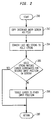
- Figure 2 depicts the procedure performed by the processor 320 to ensure that the cursor is in the proper position on the VDD 312. Flow starts at step 200 and proceeds to step 202, where the processor 320 obtains (via the link 324) a copy of the file of non-text display-generation data corresponding to the input screen for the interface which is accessed by the SDP command. It is to be recalled that the input screen has two cursor positions, one for inputting an SDP command, and one for one or more other commands.
- step 204 the processor 320 converts the last hexadecimal string in the file of non-text display-generation data into text, here ASCII, code.
- ASCII text
- step 206 it is determined whether this string of ASCII code matches the coordinate combination/pattern for the cursor position required by the SDP command. If so, flow proceeds to step 210 and from there returns to step 102 of Figure 1A. If the ASCII does not match, then flow proceeds to step 208.
- step 208 the processor 320 submits a command (via the link 324) to the processing circuitry 308 which causes the cursor to be toggled from the other of its two positions to its desired position. Flow proceeds from step 208 to step 210, and from there returns to step 102 of Figure 1A.
- Figure 4 is a Unified Modeling Diagram 400, also known as an Action Diagram or an Association Diagram, corresponding to the previous example in which an embodiment of the invention was applied to the AUTOPLEX® MCRT monitoring system and a wireless telephony system.
- Item 406 denotes actions taken by the monitoring system 304.
- Item 408 denotes actions taken by a human using the monitoring system 304 in the conventional manner.
- Item 404 denotes the actions of the implemented algorithm of Figures 1A-1D, and preferably Figure 2.
- Item 402 denotes the actions that are taken by a human user of the invention, or an automated script or calling program interacting with the program according to the invention.
- a human user wishing to get information about the BBA 8 of the Cell 60 must request information from the monitoring system 304, as denoted by item 410.
- the human user inputs a request for a screen arranged as SDP No. 2138 having information particular to Cell No. 60.
- the monitoring system 304 returns a screen of information arranged as SDP No. 2138, with information particular to Cell No. 60.
- the human user must recognize and interpret the indicators, i.e., the mix of alphanumerics and color combinations, on the VDD 312. Subsequently, the human user makes decisions, i.e., item 414, based upon this information. In the meantime, the human user has been held captive while waiting for the desired SDP indicator to be displayed. Plus, the human user is vulnerable to his ability to recognize and interpret the indicators on the VDD 312.
- a human user interacts with the program in the memory 326 being executed by the processor 320.
- the human, script or calling program submits a request to get information on BBA 8 by way of a screen arranged as SDP No. 2138 having information particular to Cell No. 60.
- the responsive action according to the invention is to automatically submit a request for a screen arranged as SDP No. 2138 having information particular to Cell No. 60.
- Item 418 is similar to item 410, except that it is automatically generated.
- the monitoring system 304 returns a screen of information arranged as SDP No. 2138, with information particular to Cell No. 60, in the same way as in step 412.
- the responsive action according to the invention is to automatically recognized and interpret the indicators in order to return the values for the text variables COLOR, STATE and VALUE that correspond to the indicator BBA 8.
- the human, script or calling program makes decisions.
- items 416, 418, 420 and 422 represent how the invention frees him from the captivity represented by item 412. If the actor 402 is the script or calling program, the subsequent decision-making is only possible because of the translation of non-text display generation data (representing an indicator featured on a screen energized according to the non-text display generation data) into text variables according to the invention as represented by items 416, 418, 420 and 422.
- Figure 5 is a state diagram 500 that extends the example represented by Figure 4.
- the state 502, link 503, state 504 and link 506 correspond to the items 416, 418, 420 and 422 of Figure 4.
- the remaining parts of Figure 5 correspond to the item 424 (Make Decisions) of Figure 4.
- State 508 represents a determination of whether BBA 8 is out of service (OOS). If not, then flow proceeds to loop back to state 502 via link 510. If BBA 8 is out of service, then flow proceeds to state 516 via link 512. At state 516, corrective actions are performed, e.g., to bring BBA 8 back into service. Flow proceeds from state 516 via link 518 to state 520, where it is determined if all the corrective actions have been performed. If not, then flow proceeds to loop back to state 516 via link 522. If all corrective actions have been performed, then flow proceeds to loop back to state 502 via link 524.
- OOS out of service
- the determination state 508 is conventionally embodied by a human, as in item 414 of Figure 4.
- the invention makes it possible to automate state 508, or at the least confirm the human's recognition and interpretation of the indicators, i.e., the mix of alphanumerics and color combinations, on the VDD 312.
- the example embodiments of the invention have translated the non-text data into text data after the aspect of extracting the groups of data (representative of the plurality of indicators) from the file of non-text display-generation data. This has the advantage of facilitating inspection of the subsequent aspects by a human because text data is more easily understood than non-text data.
- translation from non-text data to text data could alternatively take place before the aspect of extracting or before the aspect of converting.
- the invention has been described, for convenience, using the AUTOPLEX® MCRT monitoring system as a well-known example of a dedicated non-text-variable-output system.
- the invention is applicable in other dedicated non-text-variable-output systems such as those found in the air traffic control arts, train and subway control arts, chemical processing plant control arts, power generation plant control arts, etc.
- common characteristics of these non-text-variable-output systems include (1) that they hold operator captive by, and vulnerable to, the need to visually inspect their respective video display device (VDD) outputs and (2) that they are mature products for which research and development efforts have been greatly diminished, making substantive software rewrites (to obtain more user-friendly output) prohibitively expensive.
- VDD video display device
- the invention does not disturb the existing monitoring system and yet achieves a desired goal of translating the attributes of an indicator in dedicated non-text-variable-output systems into text variables that represent the characteristics of the indicator without rewriting the software of the dedicated non-text-variable-output systems.
Abstract
Description
- The invention is directed toward a technology for translating non-text data into text variables, and more particularly for translating a subset of a file of non-text display generation data into text variables representing an indicator that would be featured on a video screen energized according to the non-text display generation data.
- Large systems often include monitoring subsystems that permit one or more operators to monitor the performance of the system in general, and to specifically monitor the state of one or more parameters of the large system. In some instances, the manner in which the monitoring subsystem delivers information to the operator can become problematic.
- An example of such a monitoring subsystem is the AUTOPLEX® Maintenance CRT (MCRT) monitoring system marketed by Lucent Technologies Inc. as a tool for use with its various wireless telephony systems. The AUTOPLEX® MCRT monitoring system includes a user interface by which an operator can input a request for information concerning a parameter of the wireless telephony system. In response, the AUTOPLEX® MCRT monitoring system displays the desired information on a video screen. As the capabilities of the AUTOPLEX® MCRT monitoring system have grown, so has the amount of information that it can display per screen.
- A typical display screen partitions the viewing area into regions that have a predefined association with a parameter. The combination of attributes of a region is understood to be an indicator of the characteristics of the parameter. Typical indicator attributes might include an alphanumeric string representing a value, one of two foreground and background color combinations, whether it is blinking or not blinking, and/or whether it is not visible at all. Such a video screen is energized according to a file of non-text, i.e., hexadecimal code, display generation data. A system such as the AUTOPLEX® MCRT monitoring system can be described as a dedicated non-text-variable-output system.
- To derive meaning from such a video screen, an operator must be familiar with the predefined associations. Otherwise, the video screen appears merely to be an array of variously-colored alphanumeric strings, some of which might be blinking.
- Once an operator is familiar with such a video screen, he can submit (among other things) a Status Display Page (SDP) command to the interface to request information about a particular parameter or large system configuration. Then, the operator watches the screen until the requested array of information is displayed. Using his knowledge of the predefined associations for the requested screen, the operator looks to the region that acts as an indicator for the parameter. In that region, the operator observes the alphanumeric string, the combinations of colors and whether or not the combination is blinking, or whether the region is totally blank. In his mind, the operator translates the attributes of the indicator into the characteristics of the indicator. Usually, the characteristics of the indicator are the alphanumeric string and the state, the state being represented by the combination of colors.
- It is burdensome to the operator to have to perform this translation. Plus, it is prone to error if the operator has less than perfect recall of the predefined associations and/or attribute/characteristic relationships. A typical screen for the SDP command has about 20-30 indicators and there are over 100 screens that can be requested with the SDP command. In addition, the color relationships for an indicator on an SDP screen can change from one software release of the AUTOPLEX® MCRT monitoring system to the next. Thus, there is a great deal of information that an operator must remember about all of the SDP commands.
- Sometimes, an operator will change a parameter in the system. There might be a delay between when the operator requests the change and when it takes effect. An operator can confirm that the change has taken effect by monitoring an indicator on an SDP screen. If there is a delay in the change taking effect, then the operator must watch the video screen until the attributes of the corresponding indicator change. Until that change takes effect, the operator is held captive by the video screen.
- Suppose a parameter is critical to the operation of a component of the wireless telephony system. An operator might be assigned to verify that parameter's state is always acceptable. In theory, this requires the operator to never avert his eyes from the screen. If the appearance of the indicator changes, the operator must recognize the change in appearance and respond accordingly. Again, the operator is held captive by the video screen.
- It is desired to free the operator of the AUTOPLEX® MCRT monitoring system from the captivity represented by not being able to avert his eyes from the video screen generated in response to the SDP command, as well as to liberate operators of other similar dedicated non-text-variable-output systems. One way to do this is to rewrite the software for the system so that the characteristics of the parameters are provided in the form of text variables which can be displayed and manipulated, and not merely in the form of a file of non-text (hexadecimal code) display generation data. However, such large systems are typically mature products for which research and development efforts have been greatly diminished. This makes such a rewrite prohibitively expensive to undertake.
- The invention provides a technology for translating a subset of a file of non-text display generation data into text variables. For example, these text variables represent an indicator that would be featured on a video screen energized according to the non-text display generation data. The technology includes a method, a device that implements the method, and a computer readable medium bearing a program which causes a computer to implement the method.
- The invention is, in part, a recognition, that it is possible to translate the attributes of an indicator in a dedicated non-text-variable-output systems into text variables that represent the attributes of the indicator without rewriting the software of the dedicated non-text-variable-output systems. Rather, the file of non-text display generation data that is used to energize a video screen (with indicators) can be captured and transformed into text variables representing attributes of a desired one of the indicators, i.e., the characteristics of a corresponding desired parameter. In this way, the invention does not disturb the existing monitoring system and yet achieves the desired goal.
- The technology according to the invention is operable to: acquire a file of non-text display-generation data; extract groups of data, representative of the plurality of indicators, respectively, from either the file of non-text display-generation data or a file corresponding to it; identify one of the groups of data as corresponding to the desired indicator; and convert the identified group of data into a set of text variables having values representative of the characteristics of the desired indicator. The technology also translates the non-text data into groups of text data either before the aspect of extracting, identifying or converting. This translation explains why the aspect of extracting operates on either the file of non-text display-generation data or a file corresponding to it.
- Objectives, features and advantages of the invention will be more fully apparent from the following detailed description of the preferred embodiments, the appended claims and the accompanying drawings.
- The accompanying drawings are intended to depict example embodiments of the invention and should not be interpreted to limit the scope thereof.
- Figures 1A-1D depict a flowchart representing the method according to the invention.
- Figure 2 depicts in more detail an aspect of the method of Figure 1A.
- Figure 3 depicts the system in which the device according to the invention forms a part.
- Figure 4 is a Unified Modeling Diagram of an example use of the invention.
- Figure 5 is a state diagram that extends the example represented by Figure 4.
-
- Figures 1A-1D and 2 depict flowcharts representing the method according to the invention. This method is embodied by the device according to the invention, which is depicted as part of the overall system of Figure 3. To establish the context for Figures 1A-1D and 2, Figure 3 will be discussed first.
- Figure 3 depicts an
overall system 300 of which thedevice 306 according to the invention forms a part. The other parts of theoverall system 300 are thelarge system 302 and themonitoring system 304, examples of each of which were discussed above in the Background Section. Again, an example of thelarge system 302 is a wireless telephony system and an example of themonitoring system 304 is the AUTOPLEX® MCRT monitoring system marketed by Lucent Technologies Inc. - The
monitoring system 304 includesprocessing circuitry 308, a part of which is a video displaydriver circuit card 310. Thevideo card 310 drives a video display device (VDD) 312 with non-text, typically hexadecimal code, display-generation data supplied over aconnection 314. An input device in the form of akeyboard 316 is connected to theprocessing circuitry 308 via asignal line 318. - The
device 306 according to the invention includes aprocessor 320, an output device in the form of a video display device (VDD) 328 connected via asignal line 330, and an input device preferably in the form of akeyboard 332 connected via asignal line 334. The programmed processor has amemory 326 for storing a program or script that causes theprocessor 320 to implement the method according to the invention. Theprocessor 320 can communicate with, e.g., an input/output (I/O) port (in the case of the AUTOPLEX® MCRT monitoring system) of theprocessing circuitry 308 via abidirectional link 324. - An embodiment of the invention, for example, has been written using two languages, the Tool Command Language (TCL) and C. Only about 10% of the programming is in C to take advantage of the hexadecimal and bits translation capability of C.
- The computer-
readable memory 326 can include RAM, ROM, a fixed hard disk drive, and/or a removable storage medium for a non-fixed disk drive such as a floppy disk or a CDROM. The program which causes theprocessor 320 to implement the method according to the invention can be downloaded to theprocessor 320 from theremote host 336 over the optional connection 338. As the program is downloaded through the optional connection 338, the computer-readable medium in which the program is embodied takes the form of a propagated signal. - As can be appreciated from the description of the Figures 1A-1D and 2 below, the method according to the invention performs many sorting and comparison operations as well as accesses to look-up tables (LUTs). As such, the
processor 320 should be of sufficient processing power to assure reasonably quick results. Examples of adequate processors are those from the Pentium family of processors marketed by Intel Inc. - The method according to the invention will now be discussed in terms of the flowcharts in Figures 1A-1D and 2. Again, when an operator wishes to gather information about a parameter of the
large system 302, he uses themonitoring system 304, In particular for the AUTOPLEX® MCRT monitoring system, an operator will use the Status Display Page (SDP) command to gather information. To submit such a command to themonitoring system 304, an operator must first cause an input screen to be displayed on theVDD 312. The input screen has two cursor positions, one for inputting an SDP command, and one for another command. It is necessary to assure that the cursor is in the position allotted to an SDP command. Usually, this is done by an operator looking at the location of the cursor on the input screen and evaluating in his mind whether the cursor's position is correct. If the cursor is out of position, then the operator toggles it to the correct position. - In Figure 1A, flow starts at
step 100 and proceeds to step 101, where theprocessor 320 receives a request for information about a desired parameter of thelarge system 302 from thekeyboard 332 or from an automated script or calling program. Flow proceeds to steps 102-106, where a file of non-text, e.g., hexadecimal code in the case of the AUTOPLEX® MCRT monitoring system, display-generation data including the desired indicator (corresponding to the desired parameter) of thelarge system 302 is acquired from themonitoring system 304. - In
step 102, the proper position of the cursor on theVDD 312 is automatically assured. This automatic procedure will be discussed in more detail below in terms of Figure 2. Once the correct cursor position is assured, flow proceeds to step 104. - In
step 104, the SDP command for the desired parameter is submitted to theprocessing circuitry 308 of themonitoring system 304 by theprocessor 320 via thelink 324. An example SDP command is: 2138,60. The first number, 2138, represents the page number allotted to the particular arrangement of indicators that is desired to be retrieved. The second number, 60, represents the number allotted to the cell in a wireless system corresponding toitem 302 in Figure 3. - In response to the submitted SDP command, the
processing circuitry 308 provides a file of non-text, i.e., hexadecimal codes, display-generation data over theconnection 314 by which theVDD 312 is energized. Instep 106, via theconnection 324, theprocessor 320 acquires a copy of the file of hexadecimal code and stores it temporarily. Next, flow proceeds to steps 108-110, where groups of the hexadecimal data representing the indicators on a screen are extracted from the file of hexadecimal display-generation data. - In
step 108, theprocessor 320 parses the file of hexadecimal codes to produce a set of Indicator Data Groups. Each such group corresponds to an indicator that would be featured on the requested SDP screen and displayed on the VDD energized according to the file of hexadecimal code display-generation data. - The file of hexadecimal code display generation data includes strings of data corresponding to attributes of the indicators that would be featured on the energized video screen. These strings are denoted at the beginning by a preset datum and/or at the end by another preset datum. For the SDP command of the AUTOPLEX® MCRT monitoring system, the strings are each preceded by the hexadecimal code representing the characters "^[".
- An example of such a file of hexadecimal codes follows:
- ^[[00x1;00y1H^[[(B^[[42m^[[31m8^[[x2;y2Hact^[[00x3;00y3H^[[(B^[[42m^[[31m8 ...
-
- The characters xi and yi are variables for the coordinate values in the x and y directions.
- The
processor 320 parses, or sequentially sifts through, the file of hexadecimal codes to find the individual data strings. The parsed file is preferably stored, e.g., as an array or file in the RAM of theprocessor 320. If the parsed file is to be stored as a file having multiple lines, then the characters "^[" are found and stripped from the file, and then a new line is started. Continuing with the example, this produces the following file:
- Preferably, to ensure that the file of hexadecimal codes is valid data, the processor also searches the file to verify at least one instance of the code for the character ";" followed by the code for the character "H". As will be discussed below, these two characters are indicative of a coordinates pattern. Also, the
processor 320 verifies that the parsed file has at least, e.g., 50 lines or data strings. If either of these aspects cannot be verified, then the processor considers the file of hexadecimal codes to be either corrupted or there to have been an unsuccessful page capture. Theprocessor 320 will then resubmit the data retrieval command ofstep 104. After a third unsuccessful submission of the same data retrieval command, theprocessor 320 will terminate the algorithm and return an error notification to the user. - Each data string produced by the parsing
step 108 has color combination information, text information and screen coordinate position information. However, the strings can also have additional information (not depicted in the example discussed above). Accordingly, flow proceeds to step 110 of Figure 1B, where theprocessor 320 filters data that is not an attribute of an indicator out of the data strings. Such data to be filtered out include a linefeed datum, a carriage return datum and a null datum, plus any unnecessary (e.g., leading and trailing) whitespace characters. Flow proceeds fromstep 110 to step 112. - In
step 112, theprocessor 320 translates the data groups (strings) from hexadecimal code to text data, preferably ASCII code. Next, in steps 114-118, theprocessor 320 identifies the group of data that corresponds to the desired indicator. - Flow proceeds from
step 112 to step 114, where theprocessor 320 retrieves traits of the desired indicator that will be used to identify the corresponding data group. Again, the traits for an SDP screen indicator of the AUTOPLEX® MCRT monitoring system are coordinates, alphanumeric string and color combination (background color, foreground color, blinking or not, etc.). For output from an SDP command, the preferred trait is the screen coordinate position of the desired indicator. From one release/revision of themonitoring system 304 to another, the screen coordinate position (and the format of the coordinate representation, e.g., "[" as a prefix and "H" as a suffix, see the discussion below) of an indicator in a particular arrangement of indicators on a screen might change. To account for the possibility of multiple releases/revisions of the monitoring system, a list of all possible screen coordinate positions for each indicator in each arrangement of indicators is maintained by theprocessor 320. Instep 114, the traits are retrieved by reading the list of possible coordinate positions for desired indicator relative to the desired screen, preferably by accessing an LUT (not shown) in thememory 326. - An example of the list (or record) in the LUT (not shown) that holds the traits of the desired indicator would be: BBA8 [00x;0yH [x;yH. Here, the
numeral 8 identifies the desired indicator and the combinations 00x;0yH and x;y represent two possible screen coordinate combinations (or patterns). Here, the list/record reflects there having been two releases/revisions that have affected the coordinate information of the desired indicator. For this example, it is noted that the character, [, denotes the beginning of a coordinate attribute, while the character, H, indicates the end of a group. - It is to be recalled that the
processor 320 translates from hexadecimal code to ASCII code atstep 112. By translating to ASCII at that point, a user can comprehend the parsed file. If left as hexadecimal codes, the file would be almost unintelligible to a user. As new revisions to the AUTOPLEX® MCRT monitoring system are released, a user can inspect the saved ASCII version of the parsed file to determine if coordinate patterns have changed. If so, then the newly discovered patterns can be added to the corresponding LUT. - In
step 116, theprocessor 320 searches the parsed file for possible coordinate combinations/pattern retrieved instep 114. Atstep 118, it is determined whetherstep 116 has found a match. If not, flow proceeds to step 138 of Figure 1D, to be discussed below. If a match is found, flow proceeds tosteps 120 through 136, where the group of text data (identified as corresponding to the desired indicator) is converted into a set of text variables having values that are representative of the characteristics of the desired indicator. - Continuing with the example discussed above, an identified data group or set of data strings corresponding to an indicator would be:The

processor 320 finds the pattern [00x1;00y1H in the parsed file. The data strings associated with this pattern correspond to the following data groups up to, but not including, the next coordinates pattern. To identify the next coordinates, theprocessor 320 searches sequentially for the next occurrence of the character ";" followed by the character "H". As of now, the patterns indicative of coordinates have in common the characters ";" and "H". As new patterns arise that do not share this characteristic, the search criteria of the processor can be modified. - The identified data group in this example takes the form:Here, colordata1 = 42m, colordata2 = 31m and alphanumeric = 8. It is noted that the data string "[(B" indicates the start of the indicator attribute information.

- In
step 120 of Figure 1C, theprocessor 320 recognizes the alphanumeric string in the identified group. Instep 122, the text variable VALUE is set to be equal to the alphanumeric string fromstep 120. - In
step 124, theprocessor 120 recognizes the color data in the identified group. Color data terminates with the character "m" and, like the other data strings, starts with the character "[". Typically, as in the example above, there will be color data representing a combination of background color and foreground color, and there might also be data that causes the indicator to blink. Also, when alphanumeric data follows the color data, i.e., when alphanumeric data occurs after the character "m" on a line, this indicates the end of the color data as well as denoting the information relating to the value or state of the variable. - Sometimes, a coordinate pattern is immediately followed by an alphanumeric character without intervening color information. In that situation, the color data is the same as for the preceding attribute data group. Continuing with the example,the line or string "[x2;y2Hact" represents a coordinate pattern that is immediately followed by an alphanumeric character without intervening color information. Here the alphanumeric is "act", which represents the active state. The color data for the line "[x2;y2Hact" is the previous indicator's color data. As noted above, the start of attribute data is denoted by the characters "[(B". To find the previous indicator's color data, the processor sequentially searches backward from the line "[x2;y2Hact" to the line "[(B". Searching forward from the line "[(B", the processor identifies the color data as described above.

- In
step 126, the processor concatenates the color data to form a color data string, e.g., [colordata1 [colordata2 [colordata3. - In
step 128, theprocessor 320 retrieves an alphanumeric color word that is descriptive of the color data string, preferably by accessing an LUT (not depicted) in thememory 326 or a separate text file. An example of the alphanumeric color word corresponding to the color data string is BLACK_ON_GREEN. Instep 130 of Figure 1D, the text variable COLOR is set to the text color word. - In
step 132, theprocessor 320 uses the alphanumeric color word to retrieve an alphanumeric string that is descriptive of the state of the parameter that corresponds to the alphanumeric color word (again, made particular to the software release of the monitoring system 304). Preferably, retrieval is performed by accessing an LUT (not depicted) in thememory 326. Instep 134, theprocessor 320 sets the text variable STATE to be equal to the state-descriptive alphanumeric string.Steps steps - Step 136 follows
step 134. Instep 136, theprocessor 320 outputs the values of the text variables STATE, COLOR and TEXT, e.g., by displaying this information on theVDD 328. Continuing with the example started above, such an output would look like:The alphanumeric string, ACT, is an abbreviation of the term, active, used to describe the state of the indicator, BBA 8 (which is representative of a group of circuit boards in a cell of the wireless telephony system), and the alphanumeric 8 is the value of the indicator.
-
Step 138, it is to be recalled, is reached when it is determined atstep 118 that no match for the indicator trait(s) has/have been found. Atstep 138, theprocessor 320 sets the text variables STATE, COLOR and TEXT to the alphanumeric string, Not Shown. In the interface which is accessed by the SDP command, it is a valid condition for a indicator not to be displayed in the location where it is expected. - Figure 2 depicts the procedure performed by the
processor 320 to ensure that the cursor is in the proper position on theVDD 312. Flow starts atstep 200 and proceeds to step 202, where theprocessor 320 obtains (via the link 324) a copy of the file of non-text display-generation data corresponding to the input screen for the interface which is accessed by the SDP command. It is to be recalled that the input screen has two cursor positions, one for inputting an SDP command, and one for one or more other commands. - In
step 204, theprocessor 320 converts the last hexadecimal string in the file of non-text display-generation data into text, here ASCII, code. Atstep 206, it is determined whether this string of ASCII code matches the coordinate combination/pattern for the cursor position required by the SDP command. If so, flow proceeds to step 210 and from there returns to step 102 of Figure 1A. If the ASCII does not match, then flow proceeds to step 208. - At
step 208, theprocessor 320 submits a command (via the link 324) to theprocessing circuitry 308 which causes the cursor to be toggled from the other of its two positions to its desired position. Flow proceeds fromstep 208 to step 210, and from there returns to step 102 of Figure 1A. - Figure 4 is a Unified Modeling Diagram 400, also known as an Action Diagram or an Association Diagram, corresponding to the previous example in which an embodiment of the invention was applied to the AUTOPLEX® MCRT monitoring system and a wireless telephony system.
Item 406 denotes actions taken by themonitoring system 304.Item 408 denotes actions taken by a human using themonitoring system 304 in the conventional manner.Item 404 denotes the actions of the implemented algorithm of Figures 1A-1D, and preferably Figure 2.Item 402 denotes the actions that are taken by a human user of the invention, or an automated script or calling program interacting with the program according to the invention. - Conventionally, a human user wishing to get information about the
BBA 8 of the Cell 60 must request information from themonitoring system 304, as denoted byitem 410. Atitem 410, the human user inputs a request for a screen arranged as SDP No. 2138 having information particular to Cell No. 60. Instep 412, themonitoring system 304 returns a screen of information arranged as SDP No. 2138, with information particular to Cell No. 60. The human user must recognize and interpret the indicators, i.e., the mix of alphanumerics and color combinations, on theVDD 312. Subsequently, the human user makes decisions, i.e.,item 414, based upon this information. In the meantime, the human user has been held captive while waiting for the desired SDP indicator to be displayed. Plus, the human user is vulnerable to his ability to recognize and interpret the indicators on theVDD 312. - According to the invention, a human user, or an automated script or calling program, interacts with the program in the
memory 326 being executed by theprocessor 320. Atitem 416, the human, script or calling program submits a request to get information onBBA 8 by way of a screen arranged as SDP No. 2138 having information particular to Cell No. 60. Atitem 418, the responsive action according to the invention is to automatically submit a request for a screen arranged as SDP No. 2138 having information particular to Cell No. 60.Item 418 is similar toitem 410, except that it is automatically generated. - At
item 420, themonitoring system 304 returns a screen of information arranged as SDP No. 2138, with information particular to Cell No. 60, in the same way as instep 412. Atitem 422, the responsive action according to the invention is to automatically recognized and interpret the indicators in order to return the values for the text variables COLOR, STATE and VALUE that correspond to theindicator BBA 8. Subsequently, atitem 424, the human, script or calling program makes decisions. - If the
actor 402 is human,items item 412. If theactor 402 is the script or calling program, the subsequent decision-making is only possible because of the translation of non-text display generation data (representing an indicator featured on a screen energized according to the non-text display generation data) into text variables according to the invention as represented byitems - Figure 5 is a state diagram 500 that extends the example represented by Figure 4. In Figure 5, the
state 502, link 503,state 504 and link 506 correspond to theitems -
State 508 represents a determination of whetherBBA 8 is out of service (OOS). If not, then flow proceeds to loop back tostate 502 vialink 510. IfBBA 8 is out of service, then flow proceeds tostate 516 vialink 512. Atstate 516, corrective actions are performed, e.g., to bringBBA 8 back into service. Flow proceeds fromstate 516 vialink 518 tostate 520, where it is determined if all the corrective actions have been performed. If not, then flow proceeds to loop back tostate 516 vialink 522. If all corrective actions have been performed, then flow proceeds to loop back tostate 502 vialink 524. - The
determination state 508 is conventionally embodied by a human, as initem 414 of Figure 4. The invention makes it possible to automatestate 508, or at the least confirm the human's recognition and interpretation of the indicators, i.e., the mix of alphanumerics and color combinations, on theVDD 312. - The example embodiments of the invention have translated the non-text data into text data after the aspect of extracting the groups of data (representative of the plurality of indicators) from the file of non-text display-generation data. This has the advantage of facilitating inspection of the subsequent aspects by a human because text data is more easily understood than non-text data. However, such translation from non-text data to text data could alternatively take place before the aspect of extracting or before the aspect of converting.
- The invention has been described, for convenience, using the AUTOPLEX® MCRT monitoring system as a well-known example of a dedicated non-text-variable-output system. However, the invention is applicable in other dedicated non-text-variable-output systems such as those found in the air traffic control arts, train and subway control arts, chemical processing plant control arts, power generation plant control arts, etc. Again, common characteristics of these non-text-variable-output systems include (1) that they hold operator captive by, and vulnerable to, the need to visually inspect their respective video display device (VDD) outputs and (2) that they are mature products for which research and development efforts have been greatly diminished, making substantive software rewrites (to obtain more user-friendly output) prohibitively expensive. Thus, the invention does not disturb the existing monitoring system and yet achieves a desired goal of translating the attributes of an indicator in dedicated non-text-variable-output systems into text variables that represent the characteristics of the indicator without rewriting the software of the dedicated non-text-variable-output systems.
- The described embodiments are to be considered only non-limiting examples of the invention. The scope of the invention is to be measured by the appended claims.
Claims (37)
- In a system having a video screen energized according to a file of non-text display-generation data, a method for automatically translating a subset of said file of non-text display-generation data into text variables having values that represent characteristics of a desired one of said plurality of indicators, the method comprising:acquiring said file of non-text display-generation data;extracting groups of non-text data, representative of said plurality of indicators, respectively, from said file of non-text display-generation data;translating said groups of non-text data into groups of text data;identifying one of said groups of text data as corresponding to said desired indicator; andconverting the identified group of text data into a set of text variables having values representative of said characteristics of said desired indicator.
- The method of claim 1, wherein said video screen represents an interface that features a plurality of indicators and wherein the aspect of acquiring includes:connecting to said interface;submitting a request for predetermined arrangement of indicators on said video screen to said interface in response to which said file of non-text display-generation data will be produced; andobtaining a copy of said file of non-text display-generation data.
- The method of claim 2, wherein the aspect of acquiring further includes:assuring, before submitting said request, that a cursor on said video screen is in a predetermined location on an input screen.
- The method of claim 3, wherein the aspect of assuring includes:obtaining a copy of a file of non-text display-generation data corresponding to said input screen;translating said file of non-text display-generation data corresponding to said input screen into a file of text data;determining coordinates of said cursor in said file of text data corresponding to said input screen; andtoggling, if said coordinates of said cursor do not match said predetermined location, said cursor to said predetermined location.
- The method of claim 1, wherein the aspect of extracting includes:parsing each string of data in said file of non-text display-generation data that is bounded at the beginning and at the end by predetermined data values to produce said groups on non-text data.
- The method of claim 5, wherein said predetermined data values represent an escape character.
- The method of claim 5, wherein the aspect of extracting further includes:filtering data that do not represent characteristics of an indicator out of said groups of non-text data.
- The method of claim 1, wherein said non-text display data is hexadecimal data and said text data is ASCII data, and said aspect of translating translates from said hexadecimal data into said ASCII data.
- The method of claim 1, wherein the aspect of identifying includes:retrieving a list of at least one trait that might be possessed by the identified group of text data corresponding to said desired indicator; andsearching said groups of text data to find a match for one of the traits on said list.
- The method of claim 9, wherein said trait is a coordinate combination on said video screen for said desired indicator.
- The method of claim 9, wherein the aspect of retrieving indexes a look-up table (LUT).
- The method according to claim 9, wherein, if no groups of data match a trait on said list, then said text variables are each set to text string descriptive of there being no such indicator displayed on said video screen.
- The method of claim 1, wherein the aspect of converting includes:recognizing ones of said text data representing an alphanumeric string to be displayed on said video screen; andsetting one of said text variables to be said alphanumeric string.
- The method of claim 1, wherein the aspect of converting includes:recognizing ones of said text data representing a color to be displayed;retrieving, as a function of the recognized ones of said text data, a color-descriptive alphanumeric string describing said color to be displayed; andsetting one of said text variables to be said color-descriptive alphanumeric string.
- The method of claim 14, wherein the aspect of retrieving said descriptive alphanumeric text string indexes a look-up table (LUT).
- The method of claim 14, wherein the aspect of retrieving further includes:retrieving a version-number indicating a version of said interface; andretrieving, as a function of said version-number and said color-descriptive text string, a state-descriptive alphanumeric string descriptive of a state represented by said color-descriptive string.
- The method of claim 16, wherein the aspect of retrieving said alphanumeric state-descriptive string indexes a look-up table (LUT).
- In a system having a video screen energized according to a file of non-text display-generation data, a device for translating a subset of said non-text from said file of display-generation data into text variables having values that represent characteristics of a desired one of said plurality of indicators, the device comprising:a programmed processor; anda first interface, between said processor and said user interface, to acquire said file of non-text display-generation data;said programmed processor being operable to manipulate data in a second file, said second file being one of said file of non-text display-generation data and a file corresponding thereto, byextracting groups of data, representative of said plurality of indicators, respectively, from said second file;identifying one of said groups as corresponding to said desired indicator; andconverting the identified group into a set of text variables having values representative of said characteristics of said desired indicator,said programmed processor also being operable to translate non-text data into groups of text data either before the aspect of extracting, before the aspect of identifying or before the aspect of converting.
- For use with a system having a video screen energized according to a file of non-text display-generation data, a computer program embodied on a computer-readable medium for automatically translating a subset of said non-text from said file of display-generation data into text variables having values that represent characteristics of a desired one of said plurality of indicators, the computer program embodied on a computer-readable medium comprising:an acquisition segment for acquiring said file of non-text display-generation data; anda manipulation segment for manipulating data in a second file of data, said second file being one of said file of non-text display generation data and a file corresponding thereto, byan extraction segment for extracting groups of data, representative of said plurality of indicators, respectively, from said second file;an identification segment for identifying one of said groups data as corresponding to said desired indicator; anda conversion segment for converting the identified group of data into a set of text variables having values representative of said characteristics of said desired indicator;said manipulation segment further including a translation segment for translating non-text data into text data either before interaction by said extraction segment, before interaction by said identification segment or before interaction by said conversion segment.
- In a system having a video screen energized according to a file of non-text display-generation data, a method for automatically translating a subset of said file of non-text display-generation data into text variables having values that represent characteristics of a desired one of said plurality of indicators, the method comprising:acquiring a first file of non-text display-generation data;manipulating data in a second file of data, said second file being one of said file of non-text display generation data and a file corresponding thereto, byextracting groups of data, representative of said plurality of indicators, respectively, from said second file;identifying one of said groups of data as corresponding to said desired indicator; andconverting the identified group into a set of text variables, having values representative of said characteristics of said desired indicator;said aspect of manipulating further including translating non-text data into text data either before the aspect of extracting, before the aspect of identifying or before the aspect of converting.
- The method of claim 20, wherein the aspect of acquiring further includes:assuring, before submitting said request, that a cursor on said video screen is in a predetermined location on an input screen.
- The method of claim 21, wherein the aspect of assuring includes:obtaining a copy of a file of non-text display-generation data corresponding to said input screen;determining coordinates of said cursor in said file corresponding to said input screen; andtoggling, if said coordinates of said cursor do not match said predetermined location, said cursor to said predetermined location.
- The method of claim 21, wherein said aspect of assuring includes translating from non-text data into text data either before the aspect of determining or before the aspect of toggling.
- The method of claim 1, wherein the aspect of acquiring includes:connecting to said interface;submitting a request for predetermined arrangement of indicators on said video screen to said interface in response to which said file of non-text display-generation data will be produced; andobtaining a copy of said file of non-text display-generation data.
- The method of claim 1, wherein the aspect of extracting includes:parsing said second file to produce said groups of non-text data, said data strings being at least one of preceded and followed by predetermined data values.
- The method of claim 25, wherein said predetermined data values represent an escape character.
- The method of claim 25, wherein the aspect of extracting further includes:filtering data that do not represent characteristics of an indicator out of said groups of data.
- The method of claim 20, wherein said non-text data is hexadecimal data and said text data is ASCII data, and the aspect of translating translates from said hexadecimal data into said ASCII data.
- The method of claim 20, wherein the aspect of identifying includes:retrieving a list of at least one trait that might be possessed by the identified group of data corresponding to said desired indicator; andsearching said groups of data to find a match for one of the traits on said list.
- The method of claim 29, wherein said trait is a coordinate combination on said video screen for said desired indicator.
- The method of claim 29, wherein the aspect of retrieving indexes a look-up table (LUT).
- The method according to claim 29, wherein, if no groups of data match a trait on said list, then said text variables are each set to text string descriptive of there being no such indicator displayed on said video screen.
- The method of claim 20, wherein the aspect of converting includes:recognizing ones of said data representing an alphanumeric string to be displayed on said video screen; andsetting one of said text variables to be said alphanumeric string.
- The method of claim 20, wherein the aspect of converting includes:recognizing ones of said data representing a color to be displayed;retrieving, as a function of the recognized ones of said data, a color-descriptive alphanumeric string describing said color to be displayed; andsetting one of said text variables to be said color-descriptive alphanumeric string.
- The method of claim 34, wherein the aspect of retrieving said descriptive alphanumeric string indexes a look-up table (LUT).
- The method of claim 34, wherein the aspect of retrieving further includes:retrieving a version-number indicating a version of said interface; andretrieving, as a function of said version-number and said color-descriptive string, a state-descriptive alphanumeric string descriptive of a state represented by said color-descriptive string.
- The method of claim 36, wherein the aspect of retrieving said alphanumeric state-descriptive string indexes a look-up table (LUT).
Applications Claiming Priority (2)
| Application Number | Priority Date | Filing Date | Title |
|---|---|---|---|
| US407878 | 1999-09-29 | ||
| US09/407,878 US7080319B1 (en) | 1999-09-29 | 1999-09-29 | Technology to translate non-text display generation data representing an indicator into text variables |
Publications (2)
| Publication Number | Publication Date |
|---|---|
| EP1089213A2 true EP1089213A2 (en) | 2001-04-04 |
| EP1089213A3 EP1089213A3 (en) | 2005-07-20 |
Family
ID=23613911
Family Applications (1)
| Application Number | Title | Priority Date | Filing Date |
|---|---|---|---|
| EP00308082A Ceased EP1089213A3 (en) | 1999-09-29 | 2000-09-18 | Technology to translate non-text display generation data representing an indicator into text variables |
Country Status (4)
| Country | Link |
|---|---|
| US (2) | US7080319B1 (en) |
| EP (1) | EP1089213A3 (en) |
| JP (1) | JP2001188640A (en) |
| CA (1) | CA2319913A1 (en) |
Families Citing this family (4)
| Publication number | Priority date | Publication date | Assignee | Title |
|---|---|---|---|---|
| US7978765B2 (en) * | 2002-03-22 | 2011-07-12 | Realnetworks, Inc. | Context-adaptive macroblock type encoding/decoding methods and apparatuses |
| US7702786B2 (en) * | 2002-08-09 | 2010-04-20 | International Business Machines Corporation | Taking a resource offline in a storage network |
| US8103498B2 (en) * | 2007-08-10 | 2012-01-24 | Microsoft Corporation | Progressive display rendering of processed text |
| US20100274936A1 (en) * | 2009-04-24 | 2010-10-28 | Aten International Co., Ltd. | Osd image generating method in kvm switches |
Citations (5)
| Publication number | Priority date | Publication date | Assignee | Title |
|---|---|---|---|---|
| US4814754A (en) * | 1984-12-01 | 1989-03-21 | Fuji Electric Company Ltd. | Monitoring system |
| US5615379A (en) * | 1994-08-26 | 1997-03-25 | Sprint International Communications Corp. | Method for editing data stored in files in which the file formats are unknown |
| GB2309804A (en) * | 1996-01-31 | 1997-08-06 | Mitsubishi Electric Corp | Acquiring data |
| US5737520A (en) * | 1996-09-03 | 1998-04-07 | Hewlett-Packard Co. | Method and apparatus for correlating logic analyzer state capture data with associated application data structures |
| US5790977A (en) * | 1997-02-06 | 1998-08-04 | Hewlett-Packard Company | Data acquisition from a remote instrument via the internet |
Family Cites Families (18)
| Publication number | Priority date | Publication date | Assignee | Title |
|---|---|---|---|---|
| US4794520A (en) * | 1987-03-30 | 1988-12-27 | C-Guard Laboratories, Inc. | Interface system for computer port sharing of multiple devices |
| EP0389729A1 (en) * | 1989-03-28 | 1990-10-03 | International Business Machines Corporation | Data transmission system with a link problem determination aid (LPDA) support for all ports |
| FR2679352B1 (en) * | 1991-07-15 | 1996-12-13 | Bull Sa | UNIVERSAL DEVICE FOR COUPLING A COMPUTER BUS TO A CONTROLLER OF A GROUP OF PERIPHERALS. |
| US5235592A (en) * | 1991-08-13 | 1993-08-10 | International Business Machines Corporation | Dynamic switch protocols on a shared medium network |
| US5294982A (en) * | 1991-12-24 | 1994-03-15 | National Captioning Institute, Inc. | Method and apparatus for providing dual language captioning of a television program |
| US5619722A (en) * | 1994-01-18 | 1997-04-08 | Teramar Group, Inc. | Addressable communication port expander |
| US6295519B1 (en) * | 1995-03-03 | 2001-09-25 | Datascape, Inc. | Method and apparatus for coupling multiple computer peripherals to a computer system through a single I/O port |
| US5991830A (en) * | 1996-01-04 | 1999-11-23 | Compaq Computer Corp. | Apparatus and method for coupling multiple peripheral devices to a single port of a computer |
| US5826062A (en) * | 1996-05-30 | 1998-10-20 | International Business Machines Corporation | Method and apparatus for converting and displaying a multimedia document at a client |
| KR19980035431A (en) * | 1996-11-13 | 1998-08-05 | 김광호 | How to Convert Multilingual Input Settings |
| US5930399A (en) * | 1997-04-03 | 1999-07-27 | Microsoft Corporation | Data encoding for a communication channel supporting a subset of the characters to be transmitted |
| US6160555A (en) * | 1997-11-17 | 2000-12-12 | Hewlett Packard Company | Method for providing a cue in a computer system |
| US6363081B1 (en) * | 1998-03-04 | 2002-03-26 | Hewlett-Packard Company | System and method for sharing a network port among multiple applications |
| US6272549B1 (en) * | 1998-05-27 | 2001-08-07 | Hewlett Packard Company | Method for using electronic mail for exchanging data between computer systems |
| US6240472B1 (en) * | 1998-10-22 | 2001-05-29 | Microsoft Corporation | Method and system for sharing a communications port |
| US6282586B1 (en) * | 1998-10-28 | 2001-08-28 | 3Com Corporation | Method in an operating system, a method and system for supporting multiple hardware devices from a single communications port |
| US6505256B1 (en) * | 1999-01-15 | 2003-01-07 | Compaq Information Technologies Group, L.P. | Automatic synchronization of state colors across a web-based system |
| US6545690B1 (en) * | 1999-09-29 | 2003-04-08 | Lucent Technologies Inc. | Liaison interface |
-
1999
- 1999-09-29 US US09/407,878 patent/US7080319B1/en not_active Expired - Lifetime
-
2000
- 2000-09-18 EP EP00308082A patent/EP1089213A3/en not_active Ceased
- 2000-09-19 CA CA002319913A patent/CA2319913A1/en not_active Abandoned
- 2000-09-28 JP JP2000295389A patent/JP2001188640A/en active Pending
-
2001
- 2001-02-16 US US09/783,979 patent/US6956588B2/en not_active Expired - Lifetime
Patent Citations (5)
| Publication number | Priority date | Publication date | Assignee | Title |
|---|---|---|---|---|
| US4814754A (en) * | 1984-12-01 | 1989-03-21 | Fuji Electric Company Ltd. | Monitoring system |
| US5615379A (en) * | 1994-08-26 | 1997-03-25 | Sprint International Communications Corp. | Method for editing data stored in files in which the file formats are unknown |
| GB2309804A (en) * | 1996-01-31 | 1997-08-06 | Mitsubishi Electric Corp | Acquiring data |
| US5737520A (en) * | 1996-09-03 | 1998-04-07 | Hewlett-Packard Co. | Method and apparatus for correlating logic analyzer state capture data with associated application data structures |
| US5790977A (en) * | 1997-02-06 | 1998-08-04 | Hewlett-Packard Company | Data acquisition from a remote instrument via the internet |
Also Published As
| Publication number | Publication date |
|---|---|
| CA2319913A1 (en) | 2001-03-29 |
| US6956588B2 (en) | 2005-10-18 |
| EP1089213A3 (en) | 2005-07-20 |
| JP2001188640A (en) | 2001-07-10 |
| US7080319B1 (en) | 2006-07-18 |
| US20010034804A1 (en) | 2001-10-25 |
Similar Documents
| Publication | Publication Date | Title |
|---|---|---|
| US6708166B1 (en) | Method and apparatus for storing data as objects, constructing customized data retrieval and data processing requests, and performing householding queries | |
| US7565013B2 (en) | Character recognition method, method of processing correction history of character data, and character recognition system | |
| US8094976B2 (en) | One-screen reconciliation of business document image data, optical character recognition extracted data, and enterprise resource planning data | |
| US7047238B2 (en) | Document retrieval method and document retrieval system | |
| US6289254B1 (en) | Parts selection apparatus and parts selection system with CAD function | |
| DE10321944A1 (en) | Devices and methods for processing text-based electronic documents | |
| US20040240735A1 (en) | Intelligent text selection tool and method of operation | |
| US20040220919A1 (en) | Information searching apparatus and method, information searching program, and storage medium storing the information searching program | |
| WO2007121001A2 (en) | Method and apparatus for interactive generation of device response template and analysis | |
| US7030889B2 (en) | Data display system, data display method, computer and computer program product | |
| US20020067502A1 (en) | Methods for digitally printing composite documents | |
| US6535652B2 (en) | Image retrieval apparatus and method, and computer-readable memory therefor | |
| US7080319B1 (en) | Technology to translate non-text display generation data representing an indicator into text variables | |
| JPH10275093A (en) | Program test support device | |
| JPH07210631A (en) | Method and device for recognizing hand-written character | |
| JP2017111500A (en) | Character recognizing apparatus, and program | |
| JP4208566B2 (en) | Document image search apparatus and method, document image search system, and program | |
| US20020118876A1 (en) | Method for creating a database such as a dictionary used for a word conversion system | |
| JP2001297080A (en) | Read assisting device | |
| US7523025B2 (en) | Host terminal emulator | |
| JP4109738B2 (en) | Image processing method and apparatus and storage medium therefor | |
| JP4906044B2 (en) | Information retrieval apparatus, control method therefor, computer program, and storage medium | |
| JP4110786B2 (en) | Recognized character string correction method and apparatus, and computer program | |
| JP5253115B2 (en) | Program conversion device, program analysis device, program conversion method, program analysis method, and program | |
| US20040039747A1 (en) | Retrieval device and retrieval method for object-oriented database |
Legal Events
| Date | Code | Title | Description |
|---|---|---|---|
| PUAI | Public reference made under article 153(3) epc to a published international application that has entered the european phase |
Free format text: ORIGINAL CODE: 0009012 |
|
| AK | Designated contracting states |
Kind code of ref document: A2 Designated state(s): AT BE CH CY DE DK ES FI FR GB GR IE IT LI LU MC NL PT SE |
|
| AX | Request for extension of the european patent |
Free format text: AL;LT;LV;MK;RO;SI |
|
| PUAL | Search report despatched |
Free format text: ORIGINAL CODE: 0009013 |
|
| AK | Designated contracting states |
Kind code of ref document: A3 Designated state(s): AT BE CH CY DE DK ES FI FR GB GR IE IT LI LU MC NL PT SE |
|
| AX | Request for extension of the european patent |
Extension state: AL LT LV MK RO SI |
|
| RIC1 | Information provided on ipc code assigned before grant |
Ipc: 7G 06F 9/30 B Ipc: 7G 06F 9/45 B Ipc: 7G 06F 17/40 B Ipc: 7G 06K 9/20 A |
|
| 17P | Request for examination filed |
Effective date: 20051222 |
|
| AKX | Designation fees paid |
Designated state(s): DE FI FR GB SE |
|
| RAP3 | Party data changed (applicant data changed or rights of an application transferred) |
Owner name: LUCENT TECHNOLOGIES INC. |
|
| STAA | Information on the status of an ep patent application or granted ep patent |
Free format text: STATUS: THE APPLICATION HAS BEEN REFUSED |
|
| 18R | Application refused |
Effective date: 20090615 |