EP1091329A1 - Electronic money system and electronic money terminal device - Google Patents
Electronic money system and electronic money terminal device Download PDFInfo
- Publication number
- EP1091329A1 EP1091329A1 EP00919144A EP00919144A EP1091329A1 EP 1091329 A1 EP1091329 A1 EP 1091329A1 EP 00919144 A EP00919144 A EP 00919144A EP 00919144 A EP00919144 A EP 00919144A EP 1091329 A1 EP1091329 A1 EP 1091329A1
- Authority
- EP
- European Patent Office
- Prior art keywords
- card
- electronic money
- installment
- amount
- transaction
- Prior art date
- Legal status (The legal status is an assumption and is not a legal conclusion. Google has not performed a legal analysis and makes no representation as to the accuracy of the status listed.)
- Ceased
Links
Images


Classifications
-
- G—PHYSICS
- G07—CHECKING-DEVICES
- G07F—COIN-FREED OR LIKE APPARATUS
- G07F19/00—Complete banking systems; Coded card-freed arrangements adapted for dispensing or receiving monies or the like and posting such transactions to existing accounts, e.g. automatic teller machines
- G07F19/20—Automatic teller machines [ATMs]
-
- G—PHYSICS
- G06—COMPUTING; CALCULATING OR COUNTING
- G06Q—INFORMATION AND COMMUNICATION TECHNOLOGY [ICT] SPECIALLY ADAPTED FOR ADMINISTRATIVE, COMMERCIAL, FINANCIAL, MANAGERIAL OR SUPERVISORY PURPOSES; SYSTEMS OR METHODS SPECIALLY ADAPTED FOR ADMINISTRATIVE, COMMERCIAL, FINANCIAL, MANAGERIAL OR SUPERVISORY PURPOSES, NOT OTHERWISE PROVIDED FOR
- G06Q20/00—Payment architectures, schemes or protocols
- G06Q20/04—Payment circuits
-
- G—PHYSICS
- G06—COMPUTING; CALCULATING OR COUNTING
- G06Q—INFORMATION AND COMMUNICATION TECHNOLOGY [ICT] SPECIALLY ADAPTED FOR ADMINISTRATIVE, COMMERCIAL, FINANCIAL, MANAGERIAL OR SUPERVISORY PURPOSES; SYSTEMS OR METHODS SPECIALLY ADAPTED FOR ADMINISTRATIVE, COMMERCIAL, FINANCIAL, MANAGERIAL OR SUPERVISORY PURPOSES, NOT OTHERWISE PROVIDED FOR
- G06Q20/00—Payment architectures, schemes or protocols
- G06Q20/08—Payment architectures
- G06Q20/10—Payment architectures specially adapted for electronic funds transfer [EFT] systems; specially adapted for home banking systems
-
- G—PHYSICS
- G06—COMPUTING; CALCULATING OR COUNTING
- G06Q—INFORMATION AND COMMUNICATION TECHNOLOGY [ICT] SPECIALLY ADAPTED FOR ADMINISTRATIVE, COMMERCIAL, FINANCIAL, MANAGERIAL OR SUPERVISORY PURPOSES; SYSTEMS OR METHODS SPECIALLY ADAPTED FOR ADMINISTRATIVE, COMMERCIAL, FINANCIAL, MANAGERIAL OR SUPERVISORY PURPOSES, NOT OTHERWISE PROVIDED FOR
- G06Q20/00—Payment architectures, schemes or protocols
- G06Q20/08—Payment architectures
- G06Q20/20—Point-of-sale [POS] network systems
-
- G—PHYSICS
- G06—COMPUTING; CALCULATING OR COUNTING
- G06Q—INFORMATION AND COMMUNICATION TECHNOLOGY [ICT] SPECIALLY ADAPTED FOR ADMINISTRATIVE, COMMERCIAL, FINANCIAL, MANAGERIAL OR SUPERVISORY PURPOSES; SYSTEMS OR METHODS SPECIALLY ADAPTED FOR ADMINISTRATIVE, COMMERCIAL, FINANCIAL, MANAGERIAL OR SUPERVISORY PURPOSES, NOT OTHERWISE PROVIDED FOR
- G06Q20/00—Payment architectures, schemes or protocols
- G06Q20/22—Payment schemes or models
- G06Q20/24—Credit schemes, i.e. "pay after"
-
- G—PHYSICS
- G06—COMPUTING; CALCULATING OR COUNTING
- G06Q—INFORMATION AND COMMUNICATION TECHNOLOGY [ICT] SPECIALLY ADAPTED FOR ADMINISTRATIVE, COMMERCIAL, FINANCIAL, MANAGERIAL OR SUPERVISORY PURPOSES; SYSTEMS OR METHODS SPECIALLY ADAPTED FOR ADMINISTRATIVE, COMMERCIAL, FINANCIAL, MANAGERIAL OR SUPERVISORY PURPOSES, NOT OTHERWISE PROVIDED FOR
- G06Q20/00—Payment architectures, schemes or protocols
- G06Q20/30—Payment architectures, schemes or protocols characterised by the use of specific devices or networks
- G06Q20/36—Payment architectures, schemes or protocols characterised by the use of specific devices or networks using electronic wallets or electronic money safes
- G06Q20/367—Payment architectures, schemes or protocols characterised by the use of specific devices or networks using electronic wallets or electronic money safes involving electronic purses or money safes
-
- G—PHYSICS
- G06—COMPUTING; CALCULATING OR COUNTING
- G06Q—INFORMATION AND COMMUNICATION TECHNOLOGY [ICT] SPECIALLY ADAPTED FOR ADMINISTRATIVE, COMMERCIAL, FINANCIAL, MANAGERIAL OR SUPERVISORY PURPOSES; SYSTEMS OR METHODS SPECIALLY ADAPTED FOR ADMINISTRATIVE, COMMERCIAL, FINANCIAL, MANAGERIAL OR SUPERVISORY PURPOSES, NOT OTHERWISE PROVIDED FOR
- G06Q20/00—Payment architectures, schemes or protocols
- G06Q20/38—Payment protocols; Details thereof
- G06Q20/382—Payment protocols; Details thereof insuring higher security of transaction
-
- G—PHYSICS
- G06—COMPUTING; CALCULATING OR COUNTING
- G06Q—INFORMATION AND COMMUNICATION TECHNOLOGY [ICT] SPECIALLY ADAPTED FOR ADMINISTRATIVE, COMMERCIAL, FINANCIAL, MANAGERIAL OR SUPERVISORY PURPOSES; SYSTEMS OR METHODS SPECIALLY ADAPTED FOR ADMINISTRATIVE, COMMERCIAL, FINANCIAL, MANAGERIAL OR SUPERVISORY PURPOSES, NOT OTHERWISE PROVIDED FOR
- G06Q20/00—Payment architectures, schemes or protocols
- G06Q20/38—Payment protocols; Details thereof
- G06Q20/40—Authorisation, e.g. identification of payer or payee, verification of customer or shop credentials; Review and approval of payers, e.g. check credit lines or negative lists
- G06Q20/405—Establishing or using transaction specific rules
-
- G—PHYSICS
- G06—COMPUTING; CALCULATING OR COUNTING
- G06Q—INFORMATION AND COMMUNICATION TECHNOLOGY [ICT] SPECIALLY ADAPTED FOR ADMINISTRATIVE, COMMERCIAL, FINANCIAL, MANAGERIAL OR SUPERVISORY PURPOSES; SYSTEMS OR METHODS SPECIALLY ADAPTED FOR ADMINISTRATIVE, COMMERCIAL, FINANCIAL, MANAGERIAL OR SUPERVISORY PURPOSES, NOT OTHERWISE PROVIDED FOR
- G06Q40/00—Finance; Insurance; Tax strategies; Processing of corporate or income taxes
- G06Q40/02—Banking, e.g. interest calculation or account maintenance
Definitions
- the present invention relates to an electronic money system and electronic money terminal. It is preferably applied to electronic money systems and electronic money terminals that use information cards storing amount data on them.
- the card terminal connects to a communication line and sends information such as the card number and transaction amount to the management computer at the bank or credit company.
- the management computer at the bank or credit company manages such information as whether the card has been expired, whether the credit limit has been reached, and whether the card has been reported lost, and determines whether the card can be used, based on the card-number and payment-amount information received from the card terminal via the communication line. If it is determined that the card can be used, the management computer at the bank or credit company returns usage permission information to the sender card terminal while performing a procedure for debiting the transaction amount from the specified account of the card.
- a user wants to use an installment payment plan via credit card, he/she makes an arrangement for direct debit with the credit company and the credit company automatically debits the fixed amount decided by the arrangement from the user's account on a fixed day every month. Therefore, the user must decide the amount of each installment in advance and it is difficult for him/her to decide the amount freely when making each payment.
- the present invention has been made in view of the above problems and intends to offer an electronic money system and electronic money terminal that allow the user who uses an installment payment plan to decide the amount each time he/she makes a payment.
- the present invention accumulates the amount data equivalent to consumption as data on the transaction history of installment payments, receives part or all of the accumulated installment balance as an installment amount, subtracts the received installment amount from the installment balance to determine a new balance, and thereby allows the user to pay any part of the installment balance as an installment amount.
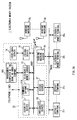
- Figure 1 generally shows the electronic money system 1 which comprises an electronic money management block 10 that issues IC cards 50, manages electronic money, and settles accounts; deposit terminals 21 x that put electronic money (amount data) into the IC cards 50; an electronic money terminal 25 x at each store 3 that receives payments from users through the IC cards 50 into which the electronic money has been put; vending machines 19 x for users to buy goods using the IC card 50; and a vending machine server 18 that receives and accumulates the transaction histories (transaction amounts, dates and times, etc.) of the IC cards 50 from the vending machines 19 x .
- various servers (security server 11, electronic money server 13, issue-data server 14, issuing device 15, integrated server 16, access server 17, and vending machine server 18) are connected to the data bus BUS1 that forms a first LAN (local area network) and various terminals (deposit terminals 21 1 to 21 n , electronic money terminals 25 1 to 25 n , and vending machines 19 1 to 19 n ) are connected to the data bus BUS2 that forms a second LAN.
- the first LAN and second LAN are connected through the access server 17.
- the security server 11 comprises a CPU 11A that operates according to an operation program stored in a storage portion 11B, as shown in Figure 3.
- the CPU 11A enters, through a communications portion 11H, the data to be exchanged, performs encryption using a proper encryption key, and carries out authentication of the communication partner via a mutual authentication portion 11C.
- the integrated server 16 comprises a CPU 16A that operates according to an operation program stored in a storage portion 16B. It captures the transaction history information such as the amount data entered through the deposit terminals 21 1 to 21 n and the transaction histories (IC card numbers, transaction amounts, dates and times, etc.) of the IC cards 50 accumulated in the respective electronic money terminals 25 1 to 25 n from a communications portion 16H through the second LAN, access server 17, first LAN, and security server 11, and stores them in a database 16C through a data bus BUS16.
- the transaction history information such as the amount data entered through the deposit terminals 21 1 to 21 n and the transaction histories (IC card numbers, transaction amounts, dates and times, etc.) of the IC cards 50 accumulated in the respective electronic money terminals 25 1 to 25 n from a communications portion 16H through the second LAN, access server 17, first LAN, and security server 11, and stores them in a database 16C through a data bus BUS16.
- the integrated server 16 has been designed to store the data, supplied by the management computer 100 at the bank or credit company, about the amounts debited automatically from users specified accounts, in the database 16C through the electronic money server 13.
- the electronic money server 13 exchanges data with the external computer 100 at the bank or credit company through an appropriate communication line and settles accounts, for example, once a month, based on various electronic money information stored in the database 16C of the integrated server 16.
- the issue server 14 registers the combination of the IC card number of the IC card 50 issued by the issuing device 15 and the credit card number of the user who possesses the IC card 50 in a database.
- the vending machine server 18 accumulates the transaction histories (transaction amounts, dates and times, etc.) of the IC cards 50 received from vending machines 19 1 to 19 n and stores them in the database 16C of the integrated server 16 through the second LAN, access server 17, first LAN, and security server 11, for example, once a day.
- the issuing device 15 in the electronic money management block 10 issues contactless read/write IC (integrated circuit) cards 50 and distributes them to users through issue counters 2 ( Figure 1) at tenant companies.
- the IC card 50 has a memory and each IC card stores a unique IC card number in its memory.
- the IC card 50 is a batteryless IC card that does not have a battery for power supply, as shown in Figures 5 and 6. It comprises a coiled loop antenna 52 for receiving the electromagnetic waves emitted by a data reader/writer 60 and converting them into electrical signals, modulation/demodulation circuit 53 for modulating send data or demodulating receive data, and control portion 54 for analyzing receive data and generating send data, all of which are mounted, for example, on a planar board 55.
- the IC card 50 receives, with the loop antenna 52, the electromagnetic waves emitted by the data reader/writer 60 and sends them to the modulation/demodulation circuit 53 as modulated waves.
- the modulation/demodulation circuit 53 demodulates the modulated waves and supplies them to the signal processing circuit 54 as send data D1 sent by the data reader/writer 60.
- the signal processing circuit 54 incorporates a control portion 59 consisting of a hard logic circuit or CPU (central processing unit) and memory portion consisting of a ROM (read only memory) 57 and RAM (random access memory) 58.
- the control portion 59 analyzes the send data D1 on the RAM 58 according to a program written on the ROM 57, reads various data D2 about electronic money stored in the RAM 58, based on the analyzed data D1, and sends out the data D2 to the modulation/demodulation circuit 53, which then modulates the data D2 and emits it as electromagnetic waves to the data reader/writer 60 through the loop antenna 52 ( Figure 5).
- the modulation/demodulation circuit 53 incorporates a power supply circuit for converting the energy of electromagnetic waves into a stable direct-current power supply. It has been designed to generate a direct-current power supply DC1 using the power supply circuit, based on the electromagnetic waves emitted by the data reader/writer 60 and received by the loop antenna 52, supply it to the control portion 59, supply the clock signal CLK1 generated based on the received electromagnetic waves to the control portion 54, and receive control signals CTL1 for various types of control from the control portion 54.
- the data reader/writer 60 inputs the various send data supplied through data bus BUS into a modulation/demodulation circuit 61. Then the modulation/demodulation circuit 61 modulates the send data using a carrier in an appropriate frequency band that can emit them efficiently as electromagnetic waves, and emits them as electromagnetic waves through a loop antenna 62.
- the data reader/writer 60 receives, with the loop antenna 62, the electromagnetic waves emitted by the IC card 50 and supplies them as modulated waves to the modulation/demodulation circuit 61. Then the modulation/demodulation circuit 61 demodulates the modulated waves and supplies them as the data sent from the IC card 50 to a signal processing portion (not shown) via the data bus BUS.
- the RAM 58 of the IC card 50 has been designed to store various electronic money information, which is stored in a plurality of files managed as a directory.
- the RAM 58 of the IC card 50 stores control information D10 consisting of the IC card number D11, file and directory definition information D12, and a file access key D13, as shown in Figure 7A, which are higher-order information in the directory structure, as well as electronic money information D20, as shown in Figure 7B, which is lower-order information in the directory structure.
- balance data D22 which represents electronic money balance
- electronic money log data D23 which represents the transaction history of the electronic money
- a Credit Card flag (described later) D24 which specifies in advance at the time of the distribution of the IC card 50 whether the shortfall can be charged to a credit card account if the balance data D22 is insufficient for a transaction amount during IC-card 50 shopping
- other user information employee number and entrance/exit data
- a Negative flag D26 described later
- an Installment Buying flag D27 which specifies at the time of the distribution of the IC card 50 whether the user can select payment in installments when he/she uses the IC card 50 for shopping.
- the deposit terminal 21 x comprises, on its exterior, a card communications portion 21D (which has the same configuration as the loop antenna 62 and modulation/demodulation circuit 61 in Figure 5) for contactless data exchange with the IC card 50, credit card communications portion 21E for reading data from the magnetic stripes of cash cards and credit cards 40, cash deposit portion 21J for depositing cash, touch panel 21T that combines a display portion 21F and operating portion 21G, and receipt output portion 21I that outputs receipts or deposit slips.
- a card communications portion 21D which has the same configuration as the loop antenna 62 and modulation/demodulation circuit 61 in Figure 5
- credit card communications portion 21E for reading data from the magnetic stripes of cash cards and credit cards 40
- cash deposit portion 21J for depositing cash
- touch panel 21T that combines a display portion 21F and operating portion 21G
- receipt output portion 21I that outputs receipts or deposit slips.
- the methods of entering amount data (electronic money) into the IC card 50 on the deposit terminal 21 x include the method in which the user deposits cash into the cash deposit portion 21I of the deposit terminal 21 x , which then writes the amount data equivalent to the deposited cash into the RAM 58 of the IC card 50, and the method in which the user inserts a cash card issued by a bank or credit card issued by a credit company into the credit card communications portion 21E and specifies a desired amount through the operating portion 21G in order for the deposit terminal 21 x to transfer the specified amount data to the IC card 50 from the specified account of the cash card or credit card.
- the term "cash card” herein means a card for using bank deposits
- the term “credit card” herein means a card issued by a credit company to extend a certain amount of loans to the user.
- a CPU 21A has been designed to perform the deposit/payment procedure shown in Figure 10 according to a program stored in a storage portion 21B.
- the CPU 21A starts the deposit/payment procedure in Step SP10 shown in Figure 10 and determines in Step SP11 whether the user wants deposit processing for entering amount data (electronic money) into the IC card 50 or payment processing for making installment payments described later.
- the CPU 21A of the deposit terminal 21 x displays selection screen for the user to select between deposit and payment, as shown in Figure 11A, on the touch panel 21T.
- the user makes a selection by pressing a Deposit selection key 21T 1 or Payment selection key 21T 2 .
- the touch panel 21T has been designed to remind the user of payments by displaying the fixed days, the pay days of installments.
- the CPU 21A of the deposit terminal 21 x decides between deposit processing and payment processing in Step SP11. If the user selects payment processing, the CPU 21A goes to Step SP80 and runs the process of receiving a payment described later.
- Step SP12 the CPU 21A goes to Step SP12, reads out information such as the card number from the IC card 50, and waits for the user to enter the deposit method via the touch panel 21T.
- the CPU 21A displays a Cash selection key 21T 11 and Cash Card/Credit Card selection key 21T 12 on the touch panel 21T for selecting between cash and a cash card or credit card as shown in Figure 11B and the user makes a selection by pressing the desired key.
- the CPU 21A opens the lid of the cash deposit portion 21J and waits for the user to deposit cash. As the user deposits cash in the cash deposit portion 21J, the CPU 21A counts the amount of the deposited cash and displays the result of counting 21T 21 on the touch panel 21T as shown in Figure 11C. If the result of counting 21T 21 is correct, the user indicates it to the CPU 21A by pressing a Confirm key 21T 2 2 displayed on the touch panel 21T. If result of counting is wrong, the user indicates it by pressing a Return key 21T 23 displayed on the touch panel 21T.
- Step SP13 that follows Step 12
- the CPU 21A returns the cash to the cash deposit portion 21J and stops deposit processing.
- the CPU 21A prompts the user to insert a cash card or credit card 40 into the credit card communications portion 21E by displaying an instruction 21T 31 to insert a card on the touch panel 21T as shown in Fig 11D and displays numeric keys 21T 41 on the touch panel 21T as shown in Fig 11E in order for the user to enter the desired amount.
- the CPU 21A goes to Step SP18 from Step SP13. At the same time, it sends the amount of the cash deposited by the user in the cash deposit portion 21J to the IC card 50 through the card communications portion 21D and sends and stores the amount data equivalent to this cash to the integrated server 16 in the electronic money management block 10 through a communications portion 21H. Consequently, the control portion 50 of the IC card 50 updates the balance data D22 ( Figure 7B) that represent the balance of this electronic money by adding the amount data received from the deposit terminal 21 x to the electronic money remaining in the RAM 58.
- the CPU 21A moves from Step SP13 to Step SP14, reads out the credit card number from the magnetic stripes of the cash card or credit card 40 inserted into the credit card communications portion 21E, and sends it together with the personal identification number of the cash card or credit card 40 entered by the user through the operating portion 21G, a request for the use of the cash card or credit card 40, and the amount to be used, to the electronic money management block 10 ( Figure 1) through the communications portion 21H.
- the mutual authentication portion 21C of the deposit terminal 21 x determines whether the party the CPU 21A is communicating with is the legitimate communication partner.
- the electronic money management block 10 sends, through a communication line, the credit card number, user-entered personal identification number, request for the use of the cash card or credit card 40, and amount to be used, received from the deposit terminal 21 x , to the management computer 100 at the bank or credit company that manages cash cards or credit cards.
- the management computer 100 at the bank or credit company manages the cash card numbers or credit card numbers and legitimate personal identification numbers of the cash cards and credit cards possessed by users. It accepts the request for the use of the credit card if the combination of the credit card number and user-entered personal identification number sent by the electronic money management block 10 is a legitimate combination.
- the management computer 100 at the bank or credit company determines whether the card is valid, based on the balance in the account specified by the cash card number or credit card number received from the electronic money management block 10, the expiration date of the cash card or credit card 40, any loss report, etc.
- the management computer 100 at the bank or credit company approves the use of this amount, notifies the electronic money management block 10 to that effect, and transfers this amount from the specified account to the integrated server 16 of the electronic money management block 10.
- the management computer 100 at the bank or credit company does not approve the use of this amount and notifies the electronic money management block 10 to that effect.
- the electronic money management block 10 sends the decision of approval or disapproval to the deposit terminal 21 x and the CPU 21A of the deposit terminal 21 x receives it via the communications portion 21H in Step SP15 in Figure 10.
- the CPU 21A moves prom Step SP16 to Step SP18 and sends the amount specified by the user to the IC card 50. Consequently, the control portion 50 of the IC card 50 updates the balance data D22 ( Figure 7B) that represent the balance of this electronic money by adding the amount data received from the deposit terminal 21 x to the electronic money remaining in the RAM 58.
- the CPU 21A prints out the receipt of the transaction from the receipt output portion 21I and finishes the deposit procedure in Step SP19.
- Step SP15 If the decision received in Step SP15 is disapproval, the CPU 21A moves prom Step SP16 to Step SP17, displays in the display portion 21F of the touch panel 21T a message stating that the cash card or credit card 40 inserted into the credit card communications portion 21E by the user is invalid, and finishes the deposit procedure in Step SP19.
- the amount data equivalent to the cash deposited is sent from the deposit terminal 21 x to the integrated server 16 of the electronic money management block 10 and stored there.
- the management computer 100 at the bank or credit company sends the amount data equivalent to the amount data (electronic money) entered for the IC card 50, from the account specified for the cash card or credit card 40 to the electronic money management block 10 and stores it in the integrated server 16.
- the integrated server 16 of the electronic money management block 10 comes to retain the amount data equivalent to the amount of the electronic money entered in the IC card 50 (via cash deposits and via card-based deposits using a cash card or credit card).
- the amount data (electronic money) the user desires is entered in the IC card 50 by various methods using cash or a cash card or credit card. Then the user can buy goods, etc. at stores using the IC card 50 containing the amount data.
- the electronic money terminal 25 x (25 1 to 25 n ) connected with a POS (pointing on sale) resister.
- the electronic money terminal 25 x comprises a main unit 25J operated by the clerk at the store where the electronic money terminal 25 x has been installed and an IC card read/write portion 25K that exchange data with the IC card 50 in a contactless manner when the user brings the IC card 50 close to that portion.
- a touch panel On the exterior of the main unit 25J is a touch panel that combines a display portion 25F and operating portion 25G which contains arithmetic keys 25G 1 , function keys 25G 2 , a 100-yen key 25G 3 , a 1000-yen key 25G 4 , etc.
- the function keys 25G 2 allow the operator to preset the prices of frequently used commodities. Then the clerk operating the main unit 25J can easily enter the prices when multiple commodities are purchased, by entering, for example, "F1 x 3 + F2 x 2" with function keys 25G 2 and arithmetic keys 25G 1 .
- the 100-yen key 25G 3 and 1000-yen key 25G 4 are used by the clerk when entering the prices of commodities with numeric keys of the arithmetic keys 25G 1 .
- the IC card read/write portion 25K comprises, on its exterior, a card communications portion 21D (with the same configuration as the loop antenna 62 and modulation/demodulation circuit 61 in Figure 5) that exchanges data with the IC card 50 in a contactless manner and a display portion 25L that displays the content of transactions.
- the electronic money terminal 25 x has been designed to determine that the user has the intension to use his/her IC card 50 (i.e., intension of consumption) when the user holds it over (holds close to) the IC card read/write portion 25K of the electronic money terminal 25 x .
- the display portion 25L comprises a sales total display portion 25L 1 that displays the sales total entered by the clerk from the operating portion 25G on the main unit 25J, balance due display portion 25L 2 that displays the balance due if there is not sufficient balance in the IC card 50, and a balance display portion 25L 3 that displays the electronic money remaining in the IC card 50 after a given use of the IC card 50.
- the CPU 25A of the electronic money terminal 25 x has been designed to perform the IC card transaction procedure shown in Figure 14 according to a program stored in a storage portion 25B.
- the CPU 25A enters the IC card transaction procedure in Step SP20 shown in Figure 14 and then determines in Step SP21 whether the user wants to use payment in electronic money or payment in installments.
- the clerk selects either an electronic money transaction or installment transaction by operating a Payment Method selection key, one of the function keys 25G 2 on the operating portion 25G according to the payment method the user wants, and then the CPU 25A determines the payment method according to the clerk's selection.
- Step SP22 If the specified payment method is payment in electronic money, the CPU 25A moves to Step SP22, reads out the card number and other information as well as past transaction history data from the IC card 50, and waits for the clerk to input the sales total from the operating portion 25G.
- the CPU 25A has been designed to read from the IC card 50 whether the Negative flag D26 ( Figure 7B) is on, and to reject the IC card 50 if the flag is on. Details of the Negative flag D26 will be described later.
- the CPU 25A goes to the next step SP23, subtracts the sales total from the balance data D22 ( Figure 7B) stored in the RAM 58 of the IC card 50, and stores the subtracted transaction amount of electronic money together with the card number and transaction date/time information of the IC card 50 in the electronic money transaction amount storage area in the storage portion 25B of the electronic money terminal 25 x .
- the transaction date/time is detected by a timer 25 T installed in the main unit 25J.
- the CPU 25A displays the appropriate amounts in the display portion 25F and balance due display portion 25L 2 , moves from Step SP24 to Step SP25, and reads the Credit Card flag stored in the IC card 50 ( Figure 7B) . If it is set to Enabled, the CPU 25A goes to Step SP26 and stores the shortfall as a credit card transaction amount in the credit card transaction amount storage area in the storage portion of the electronic money terminal 25 x .
- the amount taken in from the balance in the IC card 50 is stored as electronic money transaction information together with the card number and transaction date/time information of the IC card 50 in the storage portion 25B of the electronic money terminal 25 x while the amount consumed as the credit card transaction amount is stored as credit card transaction information together with the card number and transaction date/time information of the IC card 50 in the storage portion 25B of the electronic money terminal 25 x .
- the card number of the available credit card issued by the card company used by the user and the card number of the IC card 50 supplied to the user are registered with the issue-data server 14 ( Figure 2) of the electronic money management block 10 and the Credit Card flag D24 ( Figure 7B) in the RAM 58 of the IC card 50 is set to Enabled.
- the electronic money management block 10 uses the card number of the credit card, the electronic money management block 10 checks the validity of the card periodically with the card company, based on the expiration date, any delay in payments, any reported theft or loss, etc.
- the electronic money management block 10 sends the card number of the IC card 50 possessed by the user under whose name the card number of the invalid credit card has been registered, together with a message that the credit card is invalid, to the electronic money terminal 25 x (25 1 to 25 n ). Consequently, when the IC card 50 is used, if the electronic money balance is insufficient, the electronic money terminal 25 x (25 1 to 25 n ) displays a message that the electronic money balance is insufficient on the display portions 25F and 25L instead of charging the shortfall to the credit card and sets the Credit Card flag in the memory of the IC card 50 to Disabled.
- the electronic money terminals 25 x (25 1 to 25 n ) consume only the electronic money deposited beforehand in the IC card 50. Therefore, the CPU 25A of the electronic money terminal 25 moves from Step SP25 to Step SP27 in Figure 14 and displays a message that the credit card is invalid on the display portions 25F and 25L.
- Step SP21 in Figure 13 the CPU 25A goes to Step SP100, reads out the card number and other information as well as past transaction history data from the IC card 50, and checks the status of the Negative flag D26. If the Negative flag D26 is on, the given IC card 50 is rejected. If the Negative flag D26 is off, the CPU 25A goes to Step SP101 that follows SP100 and checks the Installment Buying flag D27 described above with reference to Figure 7B. If the Installment Buying flag D27 is off, the CPU 25A displays information to the effect that no installment buying has been registered on the display portion 25F, returns to Step SP21 described above, and waits again for a payment method to be entered again.
- the issue-data server 14 ( Figure 2) of the electronic money management block 10 registers the card number of the given IC card 50 for installment buying in the database 16C of the integrated server 16.
- Step SP102 the CPU 25A goes to Step SP102 and waits for the clerk to enter a transaction amount.
- the CPU 25A goes to Step SP103 that follows SP102 and stores the sales total as the amount to be paid in installments together with the card number and transaction date/time information of the IC card 50 in the installment amount storage area in the storage portion 25B of the electronic money terminal 25 x .
- the amount to be paid in installments is stored as installment transaction information together with the card number and transaction date/time information of the IC card 50 in the storage portion 25B of the electronic money terminal 25 x .
- the storage portion 25B operates as first accumulating means.
- the CPU 25A of the electronic money terminal 25 x naturally does not update the balance data D22 ( Figure 7B) stored in the RAM 58 of the IC card 50.
- Step SP28 When the sequence of processes for the IC card 50 transaction is complete, the CPU 25A of the electronic money terminal 25 goes to Step SP28, writes the transaction history into the RAM 58 of the IC card 50 as electronic money log data D23 ( Figure 7B), and finishes the IC card transaction procedure in Step SP29.
- the storage portion 25B of the electronic money terminal 25 keeps records of the transaction amount charged to the electronic money deposited in the IC card 50 in advance and the transaction amount charged to the credit card in case of insufficient electronic money separately as the transaction history of the IC card 50.
- the storage portion 25B stores the transaction dates/times and IC card number together with the transaction amounts as transaction history data.
- the transaction history data block contains Card Transaction information D23 1 for identifying the communication data written into the block on the side of the IC card 50, Log Type information D23 2 that represents the use form (use form such as deposit or consumption; distinction between whether a payment is covered by the electronic money balance, totally or partially by a credit card, or by installments) of electronic money in this transaction history, Date/Time information D23 3 , Terminal Number information D23 4 for identifying the electronic money terminal 25 x used, Dealing Value (transaction amount) information D23 5 in this transaction history, Key Version information D23 6 that represents the version of the encryption key used for the communication data exchanged in the IC card transaction, Balance Data information D23 7 that represents the electronic money balance remaining in the IC card after the transaction (use), Terminal Transaction information D23 8 for use by the electronic money terminal 25 x to identify the communication for this transaction (use) between the electronic money terminal 25 x and IC card 50, and Signature information D23 9 prepared using the key specified by the Key Version information D23 6 described above.
- Log Type information D23 2
- the control portion 59 of the IC card 50 has been designed to form the electronic money log data D23 consisting of one transaction history block ( Figure 15A) for each transaction.
- the transaction charged to the electronic money deposited in the IC card 50 in advance and the transaction charged to the credit card in case of insufficiency in the electronic money are treated as separate units (transaction histories) and a separate transaction history block is formed for each transaction unit.
- the CPU 25A of the electronic money terminal 25 writes card identification information D23A, shown in Figure 15B, for identifying the IC card 50 into the storage portion 25B, attaching it to the electronic money log data D23 ( Figure 15A).
- the card identification information D23A contains Card IDm D23A 1 that represents the IC card used in the electronic money log data D23 to which the card identification information 23A is attached, Terminal Transaction Flag D23A 2 that indicates whether the electronic money terminal 25 x into which the electronic money log data D23 is written is identical to the electronic money terminal 25 x where the electronic money log data D23 was prepared when the card was used, Key Version information D23A 3 that represents the version of the encryption key for the communication data used when this electronic money log data D23 is written into the electronic money terminal 25 x , and Signature information D23A 4 prepared using the key specified by the Key Version information D23A 3 .
- the CPU 25A of the electronic money terminal 25 x writes the electronic money log data D23 into the RAM 58 of the IC card 50 as well as writes it into the storage portion 25B of the electronic money terminal 25 x by attaching to it the card identification information D23A.
- the IC card 50 contains electronic money log data D23 for the past 15 uses. Each time the IC card 50 is used anew, electronic money log data D23 is written together with the card identification information D23A into the electronic money terminal 25 x where this IC card 50 is used.
- the electronic money terminal 25 x has been designed to write the electronic money log data D23 of the past 15 uses into the storage portion 25B from the IC card 50 each time the IC card 50 is used. If the Terminal Number information D23 4 contained in the past electronic money log data D23 to be written turns out to be information that represents another electronic money terminal 25 x , the Terminal Transaction Flag D23A 2 of the card identification information D23A indicates that the electronic money log data D23 represents a transaction made on another electronic money terminal 25 x . This indication is used for account settlement in the electronic money management block 10.
- one electronic money terminal 25 x stores, without redundancy, the electronic money log data D23 read from these IC cards 50 (50 1 , 50 2 , . . . . 50 n ) in the past 15 uses and new electronic money log data D23 generated this time.
- the same electronic money log data D23 of each IC card 50 (50 1 , 50 2 , . . . . 50 n ) are stored in a plurality of electronic money terminals 25 x (25 1 , 50 2 , . . . . 25 n ).
- the electronic money log data D23 stored in the electronic money terminal 25 x used for the transaction (use of the IC card) that produced this electronic money log data D23 is flagged with the Terminal Transaction Flag D23A 2 ( Figure 15B) of card identification information D23A ( Figure 15B) stored together with the electronic money log data D23.
- the electronic money log data D23 gathered in the electronic money management block 10 only the electronic money log data D23 whose Terminal Transaction Flag has been set are used for account settlement.
- each electronic money terminal 25 x stores the amount, card number, and date/time information for each use of an IC card 50 as transaction history (electronic money log data D23) and the electronic money management block 10 captures, once a day, the transaction histories of the IC cards 50 stored in the electronic money terminals 25 x (25 1 to 25 n ) .
- the electronic money management block 10 totals the credit-card transaction information of each IC card 50 at regular intervals and sends the results together with the card number of the IC card 50 to the management computer 100 at the bank or credit company, based on the credit card number registered in advance.
- the management computer at the bank or credit company debits the amount charged to the credit card from the user's account, sends it: to the electronic money management block 10, and thereby accumulates it in the integrated server 16.
- the amounts accumulated as the transaction amount of the credit card in case of an insufficient electronic money balance when the user uses his/her credit card 50 are debited collectively from the user's account by the management computer 100 at the bank or credit company and stored in the integrated server 16 of the electronic money management block 10.
- the electronic money management block 10 can ask the management computer 100 at the bank or credit company to debit the amounts for a plurality of transactions in one communication exchange. Since the use of the IC card 50 does not incur communications costs each time, the IC card 50 (credit card) can be used even for a small transaction amount.
- the electronic money management block 10 settles accounts, for example, once a month, based on the transaction histories (electronic money log data D23 and card identification information D23A) of the IC cards 50 captured collectively into the database 16C of the integrated server 16 from the electronic money terminals 25 (25 1 to 25 n ) once a day.
- Figure 17 shows the procedure in which the electronic money server 13 of the electronic money management block 10 gathers the combination (transaction histories) of electronic money log data D23 ( Figure 15A) and card identification information D23A ( Figure 15B) into the integrated server 16 from the electronic money terminals 25 x periodically (once a day, for example) and settles accounts using the transaction histories accumulated in the integrated server 16.
- the electronic money server 13 starts this procedure in Step SP40 and gathers the transaction histories accumulated in the electronic money terminals 25 x and stores them in the integrated server 16, for example, once a day in Step SP41.
- Step SP42 the electronic money server 13 determines whether now is a settlement time that occurs, for example, once a month. If it is a settlement time, the electronic money server 13 goes to Step SP43 and segregates the transaction histories whose Terminal Transaction Flag D23A 2 is on, as segregated log data, from the transaction histories accumulated in the integrated server 16.
- Step SP44 the electronic money server 13 goes to Step SP44 and compares the segregated log data with other transaction history data. If the comparison results in a mismatch, it means that the electronic money log data D23 generated when an IC card 50 was used has been lost in any of the electronic money terminals 25 x . Then the electronic money server 13 gets a negative answer in Step SP45 and goes to Step SP46.
- Step SP46 the electronic money server 13 changes the other transaction history data that does not match the segregated log data into segregated log data. Consequently, the lost electronic money log data D23 is substituted by the electronic money log data D23 read out from this IC card 50 when the IC card 50 was used on other electronic money terminals 25 x .
- the electronic money server 13 settles account using only segregated log data in Step SP47 and finishes the procedure in Step SP48.
- the electronic money server 13 starts the account settlement steps shown in Figure 18 following the Process Start instruction from the integrated server 16.
- Step SP30 it starts the account settlement procedure
- Step SP31 it classifies the transaction histories (electronic money log data D23 and card identification information D23A) gathered from the electronic money terminals, according to the time of day based on the Date/Time information D23 3 ( Figure 15A) .
- the database 16C of the integrated server 16 stores the usage fees of the electronic money system 1 at each store: the ratios of the usage fees to sales totals have been set differently depending on the time of day.
- the fee rate for the use of the IC card 50 during the period from 5 a.m. to 5 p.m. (first time period) has been set at 5%
- the fee rate during the period from 5 p.m. to 5 a.m. (second time period) has been set at 7%.
- Step SP32 the electronic money server 13 settles accounts for the electronic money log data D23 classified into the first and second time periods in Step SP31 of Figure 16, using the fee rates for each time period.
- the electronic money server 13 settles accounts for the transactions conducted during the first time period using the usage fee rate of 5% and settles accounts for the transactions conducted during the second time period using the usage fee rate of 7%.
- the electronic money server 13 After settling accounts in this way, the electronic money server 13 goes to Step SP33 where it transfers the amounts corresponding to the results of the account settlements to the accounts of individual stores from the amount data accumulated in the database 160 of the integrated server 16. In so doing, the electronic money server 13 outputs details of the transfer for each store, i.e., a detailed statement and total amounts classified by the time period and sends them to each store.
- Step SP34 the electronic money server 13 goes to Step SP34 where it adds the installment transaction data out of the electronic money log data D23 used for the account settlement process to the registration list of installment payments registered beforehand in the database 16C of the integrated server 16 according to card numbers and totals the installment balance and calculates the interests for each IC card 50. It finishes the account settlement process in Step SP35.
- the installment balance totaled for each IC card 50 is added to the past installment balance for the IC card 50 contained in the registration list of installment payments in the database 16C of the integrated server 16 and the result is saved together with its interests as a new balance. Then each time the user makes a payment via a deposit terminal 21 x ( Figures 8 and 9), the amount equivalent to the payment is deducted from the balance.
- the database 16C of the integrated server 16 operates as second accumulating means while the CPU 16A operates as balance management means.
- the deposit terminal 21 x receives the user's payment in Step SP80 described above with reference to Figure 10.
- the CPU 21A of the deposit terminal 21 x moves from Step SP80 to Step SP81 in Figure 19, where it reads the card number from the IC card 50 and receives the installment balance corresponding to this IC card from the database 16C of the integrated server 16.
- the CPU 16A of the integrated server 16 has been designed to calculate, for example, 15% of the installment balance as the minimum amount of payment and send the minimum payment information together with the installment balance to the deposit terminal 21 x .
- the integrated server 16 that calculates the minimum amount of payment and the deposit terminal 21 x compose payment receiving means.
- Step SP82 the CPU 21A displays the payment method selection screen shown in Figure 20A together with the installment balance and the minimum amount of payment on the touch panel 21T of the deposit terminal 21 x .
- the user selects a payment method by pressing an Electronic Money key 21T 6 1 or Cash key 21T 6 2.
- Step SP82 the CPU 21A moves from Step SP82 to Step SP83 where it displays numeric keys 21T 6 3 such as those shown in Figure 20B on the touch panel 21T to prompt the user to enter the amount of payment.
- Step SP84 the CPU 21A goes to Step SP84 where it deducts the amount of payment entered by the user from the electronic money balance written into the RAM 58 of the IC card 50 and informs the integrated server 16 in the electronic money management block 10 about the deduction.
- the CPU 16A of the integrated server 16 subtracts the deducted amount, as the amount of payment, from the installment balance registered in the database 16C.
- the control portion 59 of the IC card 50 updates the balance data D22 ( Figure 7A) stored in the RAM 58.
- Step SP82 the CPU 21A goes to Step SP85 where it displays the message 21T 6 4 shown in Figure 20C on the touch panel 21T prompting the user to deposit cash.
- the CPU 21A calculates the deposited cash and displays the result as a confirmation display 21T 65 such as the one shown in Figure 20D on the touch panel 21T.
- the CPU 21A displays a Confirm key 21T 66 and Return key 21T 67 on the touch panel 21T. If the user deposited a wrong amount, he/she presses the Return key 21T 67 and then the CPU 21A returns the cash to the cash deposit portion 21J and finishes this process. If the user deposited the correct amount, he/she presses the Confirm key 21T 6 6 and then the CPU 21A sends data about the amount paid, to the integrated server 16 of the electronic money management block 10. The CPU 16A of the integrated server 16 subtracts the data about the amount paid from the installment balance registered in the database 16C.
- Step SP87 the CPU 21A goes to Step SP87 where it prints a description of payment which shows the amount paid by the user this time, outputs it from the receipt output portion 21I ( Figure 8), finishes this payment processing, and finishes the deposit/payment processing in Step SP19 of Figure 10.
- Any user who loses his/her IC card 50 files a lost-card report to the electronic money management block 10 (electronic money management means, card loss handling means).
- the operator of the electronic money management block 10 identifies the lost IC card by the card number by operating the operating portion 16D consisting of, for example, a keyboard on the integrated server 16 (balance confirmation means) shown in Figure 4.
- the CPU 16A registers the card number of the lost card in the database 16C through the operating portion 16D.
- the CPU 16A of the integrated server 16 always runs the card loss handling procedure shown in Figure 21. After starting this procedure in Step SP50, the CPU 16A determines in Step SP51 whether any lost-card report has been filed (entered) .
- Step SP52 determines whether it is time to gather electronic money log data (transaction history data) D23 from the electronic money terminals 25 x (25 1 to 25 n ).
- the integrated server 16 has been designed to store the electronic money log data D23 gathered from the electronic money terminals 25 x (25 1 to 25 n ) once a day in the database 16C under the control of the electronic money server 13.
- Step SP53 stores, in the database 16C, one day of electronic money log data D23 that has been collected from the electronic money terminals 25 x (25 1 to 25 n ) by the electronic money server 13 and stored in the electronic money terminals 25 x .
- the process of Step SP53 is the same as the process of Step SP41 described above with reference to Figure 17.
- Step SP54 the CPU 16A determines whether a lost-card report was filed before the collection of electronic money log data D23 in Step SP53 described above (i.e., in the last one day before the collection of electronic money log data D23 in Step SP53).
- Step SP51 If the answer is negative, which means that no lost-card report has been filed and that there is no need to run a card loss handling process, the CPU 16A repeats the process starting with Step SP51.
- Step SP51 If the answer in Step SP51 is positive, which means that there has been a lost-card report, the CPU 16A goes to Step SP58 and sends a command to create a negative list of the lost card for stopping the use of the lost card based on the card number of the IC card 50 whose loss has been reported (hereafter referred to as a lost card) as well as an instruction to disable the lost card against any attempt to use the lost card (described later), to the electronic money terminals 25 x (25 1 to 25 n ).
- the integrated server 16 can stop the handling of the lost card by sending a command to register the lost card in the negative list and instruction to disable the lost card to the electronic money terminals 25 x .
- the integrated server 16 sends a command to create a negative list of the lost card to the electronic money terminals 25 x (25 1 to 25 n )
- the CPU 25A of each electronic money terminal 25 x creates a negative list of the lost card D58 as shown in Figure 22 and stores it in the storage portion 25B.
- a negative list D58 is created for each lost card.
- Each electronic money terminal 25 x (25 1 to 25 n ) creates a negative list as shown in Figure 22 for each lost card, so that in case of any attempt to use an IC card 59, it can determine whether the IC card 50 is a lost card by comparing the IC card number D11 ( Figure 7A) in the RAM 58 of the presented IC card 50 with the Card IDm information D58 5 in the negative list D58. The processing for the use of IC cards will be described later.
- Step SP58 the CPU 16A returns to Step SP51 described above where it determines whether there is a new lost-card report. Each time a new lost-card report is filed, the CPU 16A performs Step SP58 described above, based on the card number of the lost card reported.
- the integrated server 16 determines the balance in the lost card when the electronic money log data D23 of the lost card is gathered from the electronic money terminals 25 x for the first time after the loss of the card was reported. If the CPU 16A of the integrated server 16 gets an affirmative answer in Step SP54, it goes to Step SP55.
- the CPU 16A gathers the electronic money log data D23 of the lost card reported, based on the card number, out of the transaction histories (electronic money log data D23) of all IC cards 50 gathered from the electronic money terminals 25 x , and determines the balance using the gathered electronic money log data D23 of the lost card.
- the CPU 16A determines the electronic money balance, based on the Balance Data information D23 7 that represents the electronic money balance and that is contained in the latest electronic money log data D23, among the electronic money log data D23 described above with reference to Figure 15A.
- Step SP56 the CPU 16A goes to Step SP56 where it generates data to return the determined balance to the user, instructs the issue-data server 14 to reissue a card, and issues a new IC card 50 in place of the lost card on the issuing device 15.
- the reissued IC card 50 is assigned a card number different from the card number of the lost card. This enables the use of the reissued IC card 50 on the electronic money terminals 25 x that has suspended the use of the IC card 50 with the card number of the lost card.
- Step SP56 the CPU 16A of the integrated server 16 finishes the card loss handling procedure in Step SP57.
- the electronic money terminals 25 x When the integrated server 16 sends a command to suspend the use of the lost card and instruction to create a negative list of the lost card to the electronic money terminals 25 x in Step SP58 of the card loss handling procedure in Figure 21, the electronic money terminals 25 x additionally perform the processes for suspending and disabling the lost card as shown in Figure 23 in the process of Step SP21 in Figure 14 which is performed each time an IC card 50 is used.
- the CPU 25A of each electronic money terminal 25 x (25 1 to 25 n ) creates a negative list D58 ( Figure 22) of the lost card and stores it in the storage portion 25B. Then, starting from the day (normally the day when the negative list D58 was created) specified by the Date (start) information D58 3 ( Figure 22) in the negative list D58, each time the card number is read from this IC card 50 (Step SP21 in Figure 14), the procedure for suspending and disabling a lost card is performed for this card number starting with Step SP70 in Figure 23.
- Step SP71 the CPU 25A of each electronic money terminal 25 x (25 1 to 25 n ) checks whether the card number of the given IC card 50 matches the card number (Card IDm information D58 5 ) of any lost card registered as a negative list D58 in the storage portion 25B.
- Step SP73 finish the procedure for suspending and disabling the lost card and then returns to Step SP21 described with reference to Figure 14 to continue the IC card 50 transaction procedure.
- Step SP71 if the answer in Step SP71 is affirmative, which means that the given IC card 50 is a lost card, the CPU 25A goes to Step SP72 where it suspends the handling of this card 50 (lost card) and registers this card 50 (lost card) as disabled.
- Registration of a card as disabled is the process of disabling a lost card by setting the Negative flag D26 (Figure 7B) on the management information D10 ( Figure 7) stored in the RAM 58 ( Figure 6) of the lost card.
- the Negative flag D26 is set on the management information D10 of an IC card 50 (lost card)
- the electronic money terminal 25 x (25 1 to 25 n ) identifies the lost card by checking the Negative flag D26 as described above in relation to Step SP21 in Figure 14 and disables the IC card 50.
- the Date (end) D58 4 in the negative list D58 created or each electronic money terminal 25 x (25 1 to 25 n ) can be set, for example, to a date on and after the balance in the lost card is determined and repayment is completed in Steps SP55 and SP56 in Figure 21.
- the electronic money system 1 allows the user who uses an IC card 50 to select installment transactions.
- the transaction logs (electronic money log data D23) associated with installment transactions are accumulated first in the electronic money terminal 25 x and then gathered into the database 16C of the integrated server 16.
- the integrated server 16 specifies 15% of the total installment balance as the monthly minimum amount billed to the user (minimum amount of payment by the user). Therefore, the user should pay any amount not less than the preset minimum amount of payment through a deposit terminal 21 x by a fixed day each month.
- the user pays by electronic money or cash using his/her IC card 50 within the electronic money system 1 instead of using an external system such as debiting installments from a bank account.
- This eliminates the need to specify the amount to be debited, which would otherwise be necessary when using direct debits from a bank account, an external system, and the user can pay any amount he/she likes (not less than a minimum amount of payment) by a fixed day.
- the IC card 50 the user possesses functions as a substitute for a debit account in addition to functioning as a substitute for cash itself.
- the integrated server 16 subtracts the amount paid this time from the installment balance and saves the result of the subtraction as a new balance. Interest is charged on this new balance.
- the transaction amounts to be paid in installments are accumulated as electronic money log data D23 in the database 16 of the integrated server 16 and the user pays monthly installments by accessing the integrated server 16C through a deposit terminal 21 x , making it possible to decide monthly installments freely.
- the present invention can also employ contact IC cards.
- the transaction histories (electronic money log data D23) of IC cards 50 gathered in the electronic money terminals 25 x are collected once a day by the electronic money management block 10 which then settles accounts once a month
- the present invention can collect the transaction histories from the electronic money terminals 25 x and settle accounts at any other frequency.
- the electronic money terminal 21 x has incorporated the function of receiving installments, it is also possible to install a separate special-purpose payment machine.
- the user makes monthly installment payments by operating the electronic money terminal 21 x for himself/herself.
- the terminal that received the IC card 50 will deduct the minimum amount of payment from the IC card 50 once a month and send it to the integrated server 16 according to prior arrangements between the user and electronic money management block 10.
- the user wants to pay not less than the minimum amount of payment, he/she can make the payment by operating the electronic money terminal 21 x for himself/herself.
- the present invention can use various other rates as the minimum amount of payment. Besides, a fixed amount can be used instead of a ratio to the installment balance.
- the embodiment described above uses an IC card 50, but it is also possible to make a portable terminal such as a portable telephone, watch, and portable personal computer have the function of the IC card 50.
- a portable telephone 150 may be used instead of the IC card 50.
- the portable telephone 150 can exchange data with the deposit terminals 21 x , electronic money terminals 25 x , and vending machines 19 x in a contactless manner similarly to the case of the IC card 50.
- the portable telephone 150 has a configuration in which CPU 150A, memory 150B, transmit/receive circuit (RF) 150E for exchanging signals with a portable telephone network, baseband processor 150D for converting the RF (radio frequency) signals received by the transmit/receive circuit 150E into baseband signals and converting the baseband signals to be transmitted into RF signals, MMI (man machine interface) 150F which is an interface with a microphone 150G and speaker 150H, display portion 150I, keyboard 150J, modulator/demodulator circuit 53 for exchanging data with deposit terminals 21 x and electronic money terminals 25 x , and loop antenna 52 are connected to a data bus BUS.
- RF radio frequency
- the CPU 150A has been designed to perform various operations according to an operation program stored in the memory 150B and control various circuits according to these operations. Process details of the CPU 150A are displayed, as required, on the display portion 150I consisting of a liquid crystal display panel or the like.
- the keyboard 150J supplies data that represents this telephone number to the CPU 150A.
- the CPU 150A sends a connection request to the called party represented by the telephone number entered by the user, via the transmit/receive circuit 150E.
- the portable telephone network (not shown) connects lines according to the response from the called party.
- the transmit/receive circuit 150E supplies the RF signals received from the called party through an antenna for telephone conversations (not shown), to the baseband processor 150D, where the RF signals are converted into baseband signals.
- the baseband processor 150D supplies the resulting baseband signals to the MMI 150F and the voice signals from the called party is output as voice through the speaker 150H.
- the MMI 150F supplies the input voice signals supplied from the microphone 150G to the baseband processor 150D, where the baseband signals are converted into RF signals.
- the baseband processor 150D sends the resulting RF signals to the portable telephone network through the transmit/receive circuit 150E in order for the RF signals to be sent to the called party connected through the line. In this way, the portable telephone 150 user can talk and exchange various information with the called party.
- the portable telephone 150 comprises a modulator/demodulator circuit 53 and loop antenna 52 similar to those of the IC card 50 described with reference to Figure 5: the coiled loop antenna 52 receives the electromagnetic waves emitted by data readers/writers 60 ( Figure 5) installed in the deposit terminal 21 x , electronic money terminal 25 x , and vending machine 19 x and converts them into electrical signals while the modulation/demodulation circuit 53 modulates send data or demodulates receive data.
- the CPU 150A receives, through the bus BUS, the data received by the loop antenna 52, analyzes it, and generates send data.
- the CPU 150A can exchange electronic money data with deposit terminals 21 x , electronic money terminals 25 x , and vending machines 19 x . This makes it possible to implement applications similar to those of the IC card 50 described above with reference to Figure 5.
- the functions of the IC card 50 may be added not only to a portable telephone, but also, for example, to a watch, personal computer, etc. carried by the user.
- the electronic devices may be designed such that the IC card 50 will be inserted into them.
- amount data is entered in the IC card 50 on the deposit terminal 21 x
- the portable telephone 150 Figure 25
- the portable telephone 150 Figure 25
- a communications interface 270 for communicating with the portable telephone 150 as shown in Figure 26 with the components corresponding to those shown in Figure 2 denoted by the same reference numerals as in Figure 2, so that amount data will be entered into the portable telephone 150 through direct communications between the portable telephone 150 and electronic money management block 10 instead of using the deposit terminal 21 x
- private lines can also be used instead of telephone lines for the communications between the portable telephone 150 and electronic money management block 10.
- the IC card 50 employed by the embodiment described above is dedicated to electronic money, other functions can also be added to it depending on the usage of the memory mounted in it: a personal identification function (identification of the user possessing the IC card 50 by checking it against pre-registered personal information) such as an employee ID and a function of electronic keys such as an entrance/exit key (means of allowing entrance into and exit from an office or room that requires security clearance) as well as functions of a season ticket, driver's license, passport, insurance card, point discount card, etc.
- various functions can be added also to the portable telephone 150 and other electronic devices (watches, personal computers, etc.) that have the functions of the IC card 50 and that have been described above with reference to Figure 25.
- the present invention instead of debiting the amount data equivalent to consumption from an information card, the present invention accumulates the amount data equivalent to consumption as data on the transaction history of installment payments, receives part or all of the accumulated installment balance as an installment amount, subtracts the received installment amount from the installment balance to determine a new balance, and thereby allows the user to pay any part of the installment balance as an installment amount.
- the present invention relates to a transaction method employing electronic devices which contain monetary value as electronic money as well as to an electronic money system for it. It can be used when paying transaction amounts in installments.
Abstract
Description
- The present invention relates to an electronic money system and electronic money terminal. It is preferably applied to electronic money systems and electronic money terminals that use information cards storing amount data on them.
- Conventionally, when a user uses a cash card or credit card issued by a bank, credit company, or the like at a store where a card terminal that accepts the card has been installed, the clerk at the store makes the card terminal read the card number stored on the magnetic stripe of the card and enters the transaction amount.
- At this time, the card terminal connects to a communication line and sends information such as the card number and transaction amount to the management computer at the bank or credit company. The management computer at the bank or credit company manages such information as whether the card has been expired, whether the credit limit has been reached, and whether the card has been reported lost, and determines whether the card can be used, based on the card-number and payment-amount information received from the card terminal via the communication line. If it is determined that the card can be used, the management computer at the bank or credit company returns usage permission information to the sender card terminal while performing a procedure for debiting the transaction amount from the specified account of the card.
- There is a problem with a system that employs such cash cards or credit cards: each time the user uses his/her card, the card terminal must send a request for approval to use the card to the management computer at the bank or credit company, creating a need to connect to a communication line and thus complicating the processing of card transactions.
- If a user wants to use an installment payment plan via credit card, he/she makes an arrangement for direct debit with the credit company and the credit company automatically debits the fixed amount decided by the arrangement from the user's account on a fixed day every month. Therefore, the user must decide the amount of each installment in advance and it is difficult for him/her to decide the amount freely when making each payment.
- The present invention has been made in view of the above problems and intends to offer an electronic money system and electronic money terminal that allow the user who uses an installment payment plan to decide the amount each time he/she makes a payment.
- To solve this problem, the present invention accumulates the amount data equivalent to consumption as data on the transaction history of installment payments, receives part or all of the accumulated installment balance as an installment amount, subtracts the received installment amount from the installment balance to determine a new balance, and thereby allows the user to pay any part of the installment balance as an installment amount.
-
- Figure 1 is a block diagram showing the general configuration of the electronic money system according to the present invention.
- Figure 2 is a block diagram showing the configuration of an electronic money management block.
- Figure 3 is a block diagram showing the configuration of a security server.
- Figure 4 is a block diagram showing the configuration of an integrated server.
- Figure 5 is a schematic perspective view showing the configuration of an information card.
- Figure 6 is a block diagram showing the configuration of the information card.
- Figure 7 is a schematic view showing the data written into the information card.
- Figure 8 is a perspective view showing the appearance of a deposit terminal.
- Figure 9 is a block diagram showing the configuration of the deposit terminal.
- Figure 10 is a flow chart showing the deposit/payment procedure on the deposit terminal.
- Figure 11 is a schematic view showing a display example on the deposit terminal.
- Figure 12 is a perspective view showing the appearance of an electronic money terminal.
- Figure 13 is a block diagram showing the configuration of the electronic money terminal.
- Figure 14 is a flow chart showing an information card transaction procedure on the electronic money terminal.
- Figure 15 is a schematic view showing the structure of electronic money log data.
- Figure 16 is a schematic block diagram showing the flow of electronic money log data.
- Figure 17 is a flow chart showing the segregating procedure of log data.
- Figure 18 is a flow chart showing the account settlement procedure by the electronic money management block.
- Figure 19 is a flow chart showing the procedure for receiving a payment.
- Figure 20 is a schematic view showing a display example on the deposit terminal.
- Figure 21 is a flow chart showing the card loss handling procedure on the integrated server.
- Figure 22 is a schematic view showing the content of negative list data.
- Figure 23 is a flow chart showing the procedures for suspending and disabling a lost card on the electronic money terminal.
- Figure 24 is a block diagram showing the configuration of the electronic money system according to another embodiment.
- Figure 25 is a block diagram showing the configuration of a portable telephone according to the other embodiment.
- Figure 26 is a block diagram showing the configuration of the electronic money management block according to the other embodiment.
-
- An embodiment of the present invention will be described below with reference to the drawings.
- Figure 1 generally shows the
electronic money system 1 which comprises an electronicmoney management block 10 that issuesIC cards 50, manages electronic money, and settles accounts;deposit terminals 21x that put electronic money (amount data) into theIC cards 50; anelectronic money terminal 25x at eachstore 3 that receives payments from users through theIC cards 50 into which the electronic money has been put;vending machines 19x for users to buy goods using theIC card 50; and avending machine server 18 that receives and accumulates the transaction histories (transaction amounts, dates and times, etc.) of theIC cards 50 from thevending machines 19x. There aremultiple deposit terminals 21x,electronic money terminals 25x, andvending machines 19x. - As shown in Figure 2, in the electronic
money management block 10, various servers (security server 11,electronic money server 13, issue-data server 14, issuingdevice 15, integratedserver 16,access server 17, and vending machine server 18) are connected to the data bus BUS1 that forms a first LAN (local area network) and various terminals (deposit terminals 211 to 21n,electronic money terminals 251 to 25n, andvending machines 191 to 19n) are connected to the data bus BUS2 that forms a second LAN. The first LAN and second LAN are connected through theaccess server 17. - In the electronic
money management block 10, thesecurity server 11 comprises aCPU 11A that operates according to an operation program stored in astorage portion 11B, as shown in Figure 3. For data exchange between the integratedserver 16 and other terminals or servers, theCPU 11A enters, through acommunications portion 11H, the data to be exchanged, performs encryption using a proper encryption key, and carries out authentication of the communication partner via amutual authentication portion 11C. - As shown in Figure 4, the integrated
server 16 comprises aCPU 16A that operates according to an operation program stored in astorage portion 16B. It captures the transaction history information such as the amount data entered through thedeposit terminals 211 to 21n and the transaction histories (IC card numbers, transaction amounts, dates and times, etc.) of theIC cards 50 accumulated in the respectiveelectronic money terminals 251 to 25n from acommunications portion 16H through the second LAN,access server 17, first LAN, andsecurity server 11, and stores them in adatabase 16C through a data bus BUS16. - Also, the integrated
server 16 has been designed to store the data, supplied by themanagement computer 100 at the bank or credit company, about the amounts debited automatically from users specified accounts, in thedatabase 16C through theelectronic money server 13. - The
electronic money server 13 exchanges data with theexternal computer 100 at the bank or credit company through an appropriate communication line and settles accounts, for example, once a month, based on various electronic money information stored in thedatabase 16C of the integratedserver 16. - The
issue server 14 registers the combination of the IC card number of theIC card 50 issued by the issuingdevice 15 and the credit card number of the user who possesses theIC card 50 in a database. - The
vending machine server 18 accumulates the transaction histories (transaction amounts, dates and times, etc.) of theIC cards 50 received fromvending machines 191 to 19n and stores them in thedatabase 16C of the integratedserver 16 through the second LAN,access server 17, first LAN, andsecurity server 11, for example, once a day. - In this
electronic money system 1, the issuingdevice 15 in the electronicmoney management block 10 issues contactless read/write IC (integrated circuit)cards 50 and distributes them to users through issue counters 2 (Figure 1) at tenant companies. TheIC card 50 has a memory and each IC card stores a unique IC card number in its memory. - Thus, the
IC card 50 is a batteryless IC card that does not have a battery for power supply, as shown in Figures 5 and 6. It comprises a coiledloop antenna 52 for receiving the electromagnetic waves emitted by a data reader/writer 60 and converting them into electrical signals, modulation/demodulation circuit 53 for modulating send data or demodulating receive data, andcontrol portion 54 for analyzing receive data and generating send data, all of which are mounted, for example, on aplanar board 55. - The
IC card 50 receives, with theloop antenna 52, the electromagnetic waves emitted by the data reader/writer 60 and sends them to the modulation/demodulation circuit 53 as modulated waves. The modulation/demodulation circuit 53 demodulates the modulated waves and supplies them to thesignal processing circuit 54 as send data D1 sent by the data reader/writer 60. - The
signal processing circuit 54 incorporates acontrol portion 59 consisting of a hard logic circuit or CPU (central processing unit) and memory portion consisting of a ROM (read only memory) 57 and RAM (random access memory) 58. Thecontrol portion 59 analyzes the send data D1 on theRAM 58 according to a program written on theROM 57, reads various data D2 about electronic money stored in theRAM 58, based on the analyzed data D1, and sends out the data D2 to the modulation/demodulation circuit 53, which then modulates the data D2 and emits it as electromagnetic waves to the data reader/writer 60 through the loop antenna 52 (Figure 5). - The modulation/
demodulation circuit 53 incorporates a power supply circuit for converting the energy of electromagnetic waves into a stable direct-current power supply. It has been designed to generate a direct-current power supply DC1 using the power supply circuit, based on the electromagnetic waves emitted by the data reader/writer 60 and received by theloop antenna 52, supply it to thecontrol portion 59, supply the clock signal CLK1 generated based on the received electromagnetic waves to thecontrol portion 54, and receive control signals CTL1 for various types of control from thecontrol portion 54. - The data reader/
writer 60 inputs the various send data supplied through data bus BUS into a modulation/demodulation circuit 61. Then the modulation/demodulation circuit 61 modulates the send data using a carrier in an appropriate frequency band that can emit them efficiently as electromagnetic waves, and emits them as electromagnetic waves through aloop antenna 62. - Also, the data reader/
writer 60 receives, with theloop antenna 62, the electromagnetic waves emitted by theIC card 50 and supplies them as modulated waves to the modulation/demodulation circuit 61. Then the modulation/demodulation circuit 61 demodulates the modulated waves and supplies them as the data sent from theIC card 50 to a signal processing portion (not shown) via the data bus BUS. - The
RAM 58 of theIC card 50 has been designed to store various electronic money information, which is stored in a plurality of files managed as a directory. In other words, theRAM 58 of theIC card 50 stores control information D10 consisting of the IC card number D11, file and directory definition information D12, and a file access key D13, as shown in Figure 7A, which are higher-order information in the directory structure, as well as electronic money information D20, as shown in Figure 7B, which is lower-order information in the directory structure. As the electronic money information D20, the following data is written into each file: balance data D22 which represents electronic money balance, electronic money log data D23 which represents the transaction history of the electronic money, a Credit Card flag (described later) D24 which specifies in advance at the time of the distribution of theIC card 50 whether the shortfall can be charged to a credit card account if the balance data D22 is insufficient for a transaction amount during IC-card 50 shopping, other user information (employee number and entrance/exit data) D25, a Negative flag D26 described later, and an Installment Buying flag D27 which specifies at the time of the distribution of theIC card 50 whether the user can select payment in installments when he/she uses theIC card 50 for shopping. - The user supplied with such an
IC card 50 enters the amount data (electronic money) for a desired amount of cash into theIC card 50 on thedeposit terminal 21x shown in Figure 1, using cash, a cash card, or a credit card. As shown in Figure 8, thedeposit terminal 21x comprises, on its exterior, acard communications portion 21D (which has the same configuration as theloop antenna 62 and modulation/demodulation circuit 61 in Figure 5) for contactless data exchange with theIC card 50, creditcard communications portion 21E for reading data from the magnetic stripes of cash cards andcredit cards 40,cash deposit portion 21J for depositing cash,touch panel 21T that combines adisplay portion 21F andoperating portion 21G, and receipt output portion 21I that outputs receipts or deposit slips. - The methods of entering amount data (electronic money) into the
IC card 50 on thedeposit terminal 21x include the method in which the user deposits cash into the cash deposit portion 21I of thedeposit terminal 21x, which then writes the amount data equivalent to the deposited cash into theRAM 58 of theIC card 50, and the method in which the user inserts a cash card issued by a bank or credit card issued by a credit company into the creditcard communications portion 21E and specifies a desired amount through the operatingportion 21G in order for thedeposit terminal 21x to transfer the specified amount data to theIC card 50 from the specified account of the cash card or credit card. Incidentally, the term "cash card" herein means a card for using bank deposits and the term "credit card" herein means a card issued by a credit company to extend a certain amount of loans to the user. - As shown in Figure 9, in the
deposit terminal 21x, aCPU 21A has been designed to perform the deposit/payment procedure shown in Figure 10 according to a program stored in astorage portion 21B. As the user brings his/herIC card 50 close to thecard communications portion 21D and starts a deposit/payment operation through the operatingportion 21G, theCPU 21A starts the deposit/payment procedure in Step SP10 shown in Figure 10 and determines in Step SP11 whether the user wants deposit processing for entering amount data (electronic money) into theIC card 50 or payment processing for making installment payments described later. In so doing, theCPU 21A of thedeposit terminal 21x displays selection screen for the user to select between deposit and payment, as shown in Figure 11A, on thetouch panel 21T. The user makes a selection by pressing a Deposit selection key 21T1 or Payment selection key 21T2. Incidentally, thetouch panel 21T has been designed to remind the user of payments by displaying the fixed days, the pay days of installments. - Based on the user's selection, the
CPU 21A of thedeposit terminal 21x decides between deposit processing and payment processing in Step SP11. If the user selects payment processing, theCPU 21A goes to Step SP80 and runs the process of receiving a payment described later. - On the other hand, if the user selects deposit processing, the
CPU 21A goes to Step SP12, reads out information such as the card number from theIC card 50, and waits for the user to enter the deposit method via thetouch panel 21T. - The
CPU 21A displays a Cash selection key 21T11 and Cash Card/Credit Card selection key 21T12 on thetouch panel 21T for selecting between cash and a cash card or credit card as shown in Figure 11B and the user makes a selection by pressing the desired key. - If the user specifies cash deposit, the
CPU 21A opens the lid of thecash deposit portion 21J and waits for the user to deposit cash. As the user deposits cash in thecash deposit portion 21J, theCPU 21A counts the amount of the deposited cash and displays the result of counting 21T21 on thetouch panel 21T as shown in Figure 11C. If the result of counting 21T21 is correct, the user indicates it to theCPU 21A by pressing a Confirmkey 21T 22 displayed on thetouch panel 21T. If result of counting is wrong, the user indicates it by pressing aReturn key 21T23 displayed on thetouch panel 21T. - If the user presses the Confirm
key 21T 22, theCPU 21A goes to Step SP13 that followsStep 12, but if the user presses the Returnkey 21T 23, theCPU 21A returns the cash to thecash deposit portion 21J and stops deposit processing. - If the user specifies the deposit method using a cash card or
credit card 40 in Step SP12, theCPU 21A prompts the user to insert a cash card orcredit card 40 into the creditcard communications portion 21E by displaying aninstruction 21T31 to insert a card on thetouch panel 21T as shown in Fig 11D and displaysnumeric keys 21T41 on thetouch panel 21T as shown in Fig 11E in order for the user to enter the desired amount. - If the deposit method specified by the user is a cash deposit, the
CPU 21A goes to Step SP18 from Step SP13. At the same time, it sends the amount of the cash deposited by the user in thecash deposit portion 21J to theIC card 50 through thecard communications portion 21D and sends and stores the amount data equivalent to this cash to theintegrated server 16 in the electronicmoney management block 10 through acommunications portion 21H. Consequently, thecontrol portion 50 of theIC card 50 updates the balance data D22 (Figure 7B) that represent the balance of this electronic money by adding the amount data received from thedeposit terminal 21x to the electronic money remaining in theRAM 58. - On the other hand, if the user specifies the deposit method based on a cash card or
credit card 40, theCPU 21A moves from Step SP13 to Step SP14, reads out the credit card number from the magnetic stripes of the cash card orcredit card 40 inserted into the creditcard communications portion 21E, and sends it together with the personal identification number of the cash card orcredit card 40 entered by the user through the operatingportion 21G, a request for the use of the cash card orcredit card 40, and the amount to be used, to the electronic money management block 10 (Figure 1) through thecommunications portion 21H. At this time, the mutual authentication portion 21C of thedeposit terminal 21x determines whether the party theCPU 21A is communicating with is the legitimate communication partner. - Then the electronic
money management block 10 sends, through a communication line, the credit card number, user-entered personal identification number, request for the use of the cash card orcredit card 40, and amount to be used, received from thedeposit terminal 21x, to themanagement computer 100 at the bank or credit company that manages cash cards or credit cards. - The
management computer 100 at the bank or credit company manages the cash card numbers or credit card numbers and legitimate personal identification numbers of the cash cards and credit cards possessed by users. It accepts the request for the use of the credit card if the combination of the credit card number and user-entered personal identification number sent by the electronicmoney management block 10 is a legitimate combination. - The
management computer 100 at the bank or credit company determines whether the card is valid, based on the balance in the account specified by the cash card number or credit card number received from the electronicmoney management block 10, the expiration date of the cash card orcredit card 40, any loss report, etc. - If the specified amount is left in the specified account and the cash card or
credit card 40 is valid, themanagement computer 100 at the bank or credit company approves the use of this amount, notifies the electronicmoney management block 10 to that effect, and transfers this amount from the specified account to theintegrated server 16 of the electronicmoney management block 10. On the other hand, if the balance in the specified account is not enough to cover the specified amount or if the use of the card is not approved due to the expiration date of the cash card orcredit card 40, a reported loss or for other reasons, themanagement computer 100 at the bank or credit company does not approve the use of this amount and notifies the electronicmoney management block 10 to that effect. - The electronic
money management block 10 sends the decision of approval or disapproval to thedeposit terminal 21x and theCPU 21A of thedeposit terminal 21x receives it via thecommunications portion 21H in Step SP15 in Figure 10. - If the decision is approval, the
CPU 21A moves prom Step SP16 to Step SP18 and sends the amount specified by the user to theIC card 50. Consequently, thecontrol portion 50 of theIC card 50 updates the balance data D22 (Figure 7B) that represent the balance of this electronic money by adding the amount data received from thedeposit terminal 21x to the electronic money remaining in theRAM 58. - The
CPU 21A prints out the receipt of the transaction from the receipt output portion 21I and finishes the deposit procedure in Step SP19. - If the decision received in Step SP15 is disapproval, the
CPU 21A moves prom Step SP16 to Step SP17, displays in thedisplay portion 21F of thetouch panel 21T a message stating that the cash card orcredit card 40 inserted into the creditcard communications portion 21E by the user is invalid, and finishes the deposit procedure in Step SP19. - Thus, if the user enters desired amount data (electronic money) for the
IC card 50 in cash, the amount data equivalent to the cash deposited is sent from thedeposit terminal 21x to theintegrated server 16 of the electronicmoney management block 10 and stored there. If the user enters desired amount data (electronic money) for theIC card 50 using a cash card orcredit card 40, themanagement computer 100 at the bank or credit company sends the amount data equivalent to the amount data (electronic money) entered for theIC card 50, from the account specified for the cash card orcredit card 40 to the electronicmoney management block 10 and stores it in theintegrated server 16. - Consequently, the
integrated server 16 of the electronicmoney management block 10 comes to retain the amount data equivalent to the amount of the electronic money entered in the IC card 50 (via cash deposits and via card-based deposits using a cash card or credit card). - In this way, the amount data (electronic money) the user desires is entered in the
IC card 50 by various methods using cash or a cash card or credit card. Then the user can buy goods, etc. at stores using theIC card 50 containing the amount data. - Stores are provided with an electronic money terminal 25x (251 to 25n) connected with a POS (pointing on sale) resister. As shown in Figure 12, the
electronic money terminal 25x comprises amain unit 25J operated by the clerk at the store where theelectronic money terminal 25x has been installed and an IC card read/write portion 25K that exchange data with theIC card 50 in a contactless manner when the user brings theIC card 50 close to that portion. - On the exterior of the
main unit 25J is a touch panel that combines adisplay portion 25F andoperating portion 25G which containsarithmetic keys 25G1,function keys 25G2, a 100-yen key 25G3, a 1000-yen key 25G4, etc. Thefunction keys 25G2 allow the operator to preset the prices of frequently used commodities. Then the clerk operating themain unit 25J can easily enter the prices when multiple commodities are purchased, by entering, for example,function keys 25G2 andarithmetic keys 25G1. Incidentally, the 100-yen key 25G3 and 1000-yen key 25G4 are used by the clerk when entering the prices of commodities with numeric keys of thearithmetic keys 25G1. - The IC card read/
write portion 25K comprises, on its exterior, acard communications portion 21D (with the same configuration as theloop antenna 62 and modulation/demodulation circuit 61 in Figure 5) that exchanges data with theIC card 50 in a contactless manner and adisplay portion 25L that displays the content of transactions. Theelectronic money terminal 25x has been designed to determine that the user has the intension to use his/her IC card 50 (i.e., intension of consumption) when the user holds it over (holds close to) the IC card read/write portion 25K of theelectronic money terminal 25x. - The
display portion 25L comprises a salestotal display portion 25L1 that displays the sales total entered by the clerk from the operatingportion 25G on themain unit 25J, balancedue display portion 25L2 that displays the balance due if there is not sufficient balance in theIC card 50, and abalance display portion 25L3 that displays the electronic money remaining in theIC card 50 after a given use of theIC card 50. - As shown in Figure 13, the
CPU 25A of theelectronic money terminal 25x has been designed to perform the IC card transaction procedure shown in Figure 14 according to a program stored in astorage portion 25B. As the user brings his/herIC card 50 close to thecard communications portion 25D of the IC card read/write portion 25K and the clerk starts a transaction from the operatingportion 25G of themain unit 25J, theCPU 25A enters the IC card transaction procedure in Step SP20 shown in Figure 14 and then determines in Step SP21 whether the user wants to use payment in electronic money or payment in installments. That is, the clerk selects either an electronic money transaction or installment transaction by operating a Payment Method selection key, one of thefunction keys 25G2 on the operatingportion 25G according to the payment method the user wants, and then theCPU 25A determines the payment method according to the clerk's selection. - If the specified payment method is payment in electronic money, the
CPU 25A moves to Step SP22, reads out the card number and other information as well as past transaction history data from theIC card 50, and waits for the clerk to input the sales total from the operatingportion 25G. - Incidentally, the
CPU 25A has been designed to read from theIC card 50 whether the Negative flag D26 (Figure 7B) is on, and to reject theIC card 50 if the flag is on. Details of the Negative flag D26 will be described later. - When the clerk enters the prices of commodities via the operating
portion 25G, theCPU 25A goes to the next step SP23, subtracts the sales total from the balance data D22 (Figure 7B) stored in theRAM 58 of theIC card 50, and stores the subtracted transaction amount of electronic money together with the card number and transaction date/time information of theIC card 50 in the electronic money transaction amount storage area in thestorage portion 25B of theelectronic money terminal 25x. Incidentally, the transaction date/time is detected by atimer 25T installed in themain unit 25J. - If the spending is larger than the electronic money balance stored in the
IC card 50, theCPU 25A displays the appropriate amounts in thedisplay portion 25F and balancedue display portion 25L2, moves from Step SP24 to Step SP25, and reads the Credit Card flag stored in the IC card 50 (Figure 7B) . If it is set to Enabled, theCPU 25A goes to Step SP26 and stores the shortfall as a credit card transaction amount in the credit card transaction amount storage area in the storage portion of theelectronic money terminal 25x. - Consequently, the amount taken in from the balance in the
IC card 50 is stored as electronic money transaction information together with the card number and transaction date/time information of theIC card 50 in thestorage portion 25B of theelectronic money terminal 25x while the amount consumed as the credit card transaction amount is stored as credit card transaction information together with the card number and transaction date/time information of theIC card 50 in thestorage portion 25B of theelectronic money terminal 25x. - Incidentally, when the
IC card 50 is supplied to the user, the card number of the available credit card issued by the card company used by the user and the card number of theIC card 50 supplied to the user are registered with the issue-data server 14 (Figure 2) of the electronicmoney management block 10 and the Credit Card flag D24 (Figure 7B) in theRAM 58 of theIC card 50 is set to Enabled. Using the card number of the credit card, the electronicmoney management block 10 checks the validity of the card periodically with the card company, based on the expiration date, any delay in payments, any reported theft or loss, etc. - If the check shows that the credit card is invalid, the electronic
money management block 10 sends the card number of theIC card 50 possessed by the user under whose name the card number of the invalid credit card has been registered, together with a message that the credit card is invalid, to the electronic money terminal 25x (251 to 25n). Consequently, when theIC card 50 is used, if the electronic money balance is insufficient, the electronic money terminal 25x (251 to 25n) displays a message that the electronic money balance is insufficient on thedisplay portions IC card 50 to Disabled. - If the Credit Card flag in the memory of the
IC card 50 is changed to Disabled, the electronic money terminals 25x (251 to 25n) consume only the electronic money deposited beforehand in theIC card 50. Therefore, theCPU 25A of theelectronic money terminal 25 moves from Step SP25 to Step SP27 in Figure 14 and displays a message that the credit card is invalid on thedisplay portions - On the other hand, if payment in installments is selected in Step SP21 in Figure 13, the
CPU 25A goes to Step SP100, reads out the card number and other information as well as past transaction history data from theIC card 50, and checks the status of the Negative flag D26. If the Negative flag D26 is on, the givenIC card 50 is rejected. If the Negative flag D26 is off, theCPU 25A goes to Step SP101 that follows SP100 and checks the Installment Buying flag D27 described above with reference to Figure 7B. If the Installment Buying flag D27 is off, theCPU 25A displays information to the effect that no installment buying has been registered on thedisplay portion 25F, returns to Step SP21 described above, and waits again for a payment method to be entered again. - Incidentally, when the
IC card 50 is supplied to the user, if the user wants an installment transaction, the issue-data server 14 (Figure 2) of the electronicmoney management block 10 registers the card number of the givenIC card 50 for installment buying in thedatabase 16C of theintegrated server 16. - Therefore, if the Installment Buying flag D27 for the
IC card 50 is on, theCPU 25A goes to Step SP102 and waits for the clerk to enter a transaction amount. When the clerk enters the prices of commodities via the operatingportion 25G, theCPU 25A goes to Step SP103 that follows SP102 and stores the sales total as the amount to be paid in installments together with the card number and transaction date/time information of theIC card 50 in the installment amount storage area in thestorage portion 25B of theelectronic money terminal 25x. - Consequently, the amount to be paid in installments is stored as installment transaction information together with the card number and transaction date/time information of the
IC card 50 in thestorage portion 25B of theelectronic money terminal 25x. In this case, thestorage portion 25B operates as first accumulating means. - Incidentally, when an installment transaction is used, the
CPU 25A of theelectronic money terminal 25x naturally does not update the balance data D22 (Figure 7B) stored in theRAM 58 of theIC card 50. - When the sequence of processes for the
IC card 50 transaction is complete, theCPU 25A of theelectronic money terminal 25 goes to Step SP28, writes the transaction history into theRAM 58 of theIC card 50 as electronic money log data D23 (Figure 7B), and finishes the IC card transaction procedure in Step SP29. - Consequently, the
storage portion 25B of theelectronic money terminal 25 keeps records of the transaction amount charged to the electronic money deposited in theIC card 50 in advance and the transaction amount charged to the credit card in case of insufficient electronic money separately as the transaction history of theIC card 50. Incidentally, thestorage portion 25B stores the transaction dates/times and IC card number together with the transaction amounts as transaction history data. - Regarding the electronic money log data D23 (Figure 7B) written into the
RAM 58 of theIC card 50, 32-byte data consisting of 12 items, for example, constitutes one transaction history data block as shown in Figure 15A and the past 15 transaction history data blocks (15 times of use) are written cyclically. - The transaction history data block contains Card Transaction information D231 for identifying the communication data written into the block on the side of the
IC card 50, Log Type information D232 that represents the use form (use form such as deposit or consumption; distinction between whether a payment is covered by the electronic money balance, totally or partially by a credit card, or by installments) of electronic money in this transaction history, Date/Time information D233, Terminal Number information D234 for identifying theelectronic money terminal 25x used, Dealing Value (transaction amount) information D235 in this transaction history, Key Version information D236 that represents the version of the encryption key used for the communication data exchanged in the IC card transaction, Balance Data information D237 that represents the electronic money balance remaining in the IC card after the transaction (use), Terminal Transaction information D238 for use by theelectronic money terminal 25x to identify the communication for this transaction (use) between theelectronic money terminal 25x andIC card 50, and Signature information D239 prepared using the key specified by the Key Version information D236 described above. - In this way, the
control portion 59 of theIC card 50 has been designed to form the electronic money log data D23 consisting of one transaction history block (Figure 15A) for each transaction. Regarding the transaction unit in this case, the transaction charged to the electronic money deposited in theIC card 50 in advance and the transaction charged to the credit card in case of insufficiency in the electronic money are treated as separate units (transaction histories) and a separate transaction history block is formed for each transaction unit. - The electronic money log data D23 prepared each time the
IC card 50 is used, is accumulated in thestorage portion 25B of theelectronic money terminal 25x in Steps SP23, SP26 and SP 103 of the IC card transaction procedure described above with reference to Figure 14 as well as written into theRAM 58 of theIC card 50 in Step SP28 described above with reference to Figure 14. - The
CPU 25A of theelectronic money terminal 25 writes card identification information D23A, shown in Figure 15B, for identifying theIC card 50 into thestorage portion 25B, attaching it to the electronic money log data D23 (Figure 15A). - The card identification information D23A contains Card IDm D23A1 that represents the IC card used in the electronic money log data D23 to which the card identification information 23A is attached, Terminal Transaction Flag D23A2 that indicates whether the
electronic money terminal 25x into which the electronic money log data D23 is written is identical to theelectronic money terminal 25x where the electronic money log data D23 was prepared when the card was used, Key Version information D23A3 that represents the version of the encryption key for the communication data used when this electronic money log data D23 is written into theelectronic money terminal 25x, and Signature information D23A4 prepared using the key specified by the Key Version information D23A3. - Incidentally, at the time of the card use when this electronic money log data D23 is prepared, the
CPU 25A of theelectronic money terminal 25x writes the electronic money log data D23 into theRAM 58 of theIC card 50 as well as writes it into thestorage portion 25B of theelectronic money terminal 25x by attaching to it the card identification information D23A. TheIC card 50 contains electronic money log data D23 for the past 15 uses. Each time theIC card 50 is used anew, electronic money log data D23 is written together with the card identification information D23A into theelectronic money terminal 25x where thisIC card 50 is used. - Thus, the
electronic money terminal 25x has been designed to write the electronic money log data D23 of the past 15 uses into thestorage portion 25B from theIC card 50 each time theIC card 50 is used. If the Terminal Number information D234 contained in the past electronic money log data D23 to be written turns out to be information that represents anotherelectronic money terminal 25x, the Terminal Transaction Flag D23A2 of the card identification information D23A indicates that the electronic money log data D23 represents a transaction made on anotherelectronic money terminal 25x. This indication is used for account settlement in the electronicmoney management block 10. - Incidentally, as shown in Figure 16, since the electronic money log data D23(11) to D23(151), D23(12) to D23(152), D23(1n) to D23(15n) of the past 15 uses stored in each IC card 50 (501, 502, . . . . . 50n) are written into the
electronic money terminal 25x each time the IC card 50 (501, 502, . . . . . 50n) is used, if thesame IC card 50 is used on the sameelectronic money terminal 25x multiple times, the same electronic money log data D23 may be written into thiselectronic money terminal 25x multiple times. In that case, however, theCPU 25A of theelectronic money terminal 25 discards the redundant electronic money log data D23, based on the Card Transaction S/N (A) information D231 in the electronic money log data D23 shown in Figure 15. - Consequently, when IC cards 50 (501, 502, . . . . . 50n) are used, one
electronic money terminal 25x stores, without redundancy, the electronic money log data D23 read from these IC cards 50 (501, 502, . . . . . 50n) in the past 15 uses and new electronic money log data D23 generated this time. - Under this condition, the same electronic money log data D23 of each IC card 50 (501, 502, . . . . . 50n) are stored in a plurality of electronic money terminals 25x (251, 502, . . . . . 25n). However, of the same electronic money log data D23 stored scatteringly in these
electronic money terminals 25x, the electronic money log data D23 stored in theelectronic money terminal 25x used for the transaction (use of the IC card) that produced this electronic money log data D23 is flagged with the Terminal Transaction Flag D23A2 (Figure 15B) of card identification information D23A (Figure 15B) stored together with the electronic money log data D23. Of the electronic money log data D23 gathered in the electronicmoney management block 10, only the electronic money log data D23 whose Terminal Transaction Flag has been set are used for account settlement. - Thus, each
electronic money terminal 25x stores the amount, card number, and date/time information for each use of anIC card 50 as transaction history (electronic money log data D23) and the electronicmoney management block 10 captures, once a day, the transaction histories of theIC cards 50 stored in the electronic money terminals 25x (251 to 25n) . - Of the IC-card transaction history information (electronic money log data D23 and card identification information D23A) captured from the electronic money terminals 25x (251 to 25n), the electronic
money management block 10 totals the credit-card transaction information of eachIC card 50 at regular intervals and sends the results together with the card number of theIC card 50 to themanagement computer 100 at the bank or credit company, based on the credit card number registered in advance. - Then the management computer at the bank or credit company debits the amount charged to the credit card from the user's account, sends it: to the electronic
money management block 10, and thereby accumulates it in theintegrated server 16. - Therefore, the amounts accumulated as the transaction amount of the credit card in case of an insufficient electronic money balance when the user uses his/her
credit card 50 are debited collectively from the user's account by themanagement computer 100 at the bank or credit company and stored in theintegrated server 16 of the electronicmoney management block 10. - In this way, if the electronic money balance is insufficient when the user uses his/her
IC card 10, by debiting the amounts charged to a credit card collectively later instead of making themanagement computer 100 at the bank or credit company debit the amounts at once, the electronicmoney management block 10 can ask themanagement computer 100 at the bank or credit company to debit the amounts for a plurality of transactions in one communication exchange. Since the use of theIC card 50 does not incur communications costs each time, the IC card 50 (credit card) can be used even for a small transaction amount. - The electronic
money management block 10 settles accounts, for example, once a month, based on the transaction histories (electronic money log data D23 and card identification information D23A) of theIC cards 50 captured collectively into thedatabase 16C of theintegrated server 16 from the electronic money terminals 25 (251 to 25n) once a day. - Figure 17 shows the procedure in which the
electronic money server 13 of the electronicmoney management block 10 gathers the combination (transaction histories) of electronic money log data D23 (Figure 15A) and card identification information D23A (Figure 15B) into theintegrated server 16 from theelectronic money terminals 25x periodically (once a day, for example) and settles accounts using the transaction histories accumulated in theintegrated server 16. Theelectronic money server 13 starts this procedure in Step SP40 and gathers the transaction histories accumulated in theelectronic money terminals 25x and stores them in theintegrated server 16, for example, once a day in Step SP41. - In Step SP42, the
electronic money server 13 determines whether now is a settlement time that occurs, for example, once a month. If it is a settlement time, theelectronic money server 13 goes to Step SP43 and segregates the transaction histories whose Terminal Transaction Flag D23A2 is on, as segregated log data, from the transaction histories accumulated in theintegrated server 16. - Then, the
electronic money server 13 goes to Step SP44 and compares the segregated log data with other transaction history data. If the comparison results in a mismatch, it means that the electronic money log data D23 generated when anIC card 50 was used has been lost in any of theelectronic money terminals 25x. Then theelectronic money server 13 gets a negative answer in Step SP45 and goes to Step SP46. - In Step SP46, the
electronic money server 13 changes the other transaction history data that does not match the segregated log data into segregated log data. Consequently, the lost electronic money log data D23 is substituted by the electronic money log data D23 read out from thisIC card 50 when theIC card 50 was used on otherelectronic money terminals 25x. - Thus, the
electronic money server 13 settles account using only segregated log data in Step SP47 and finishes the procedure in Step SP48. - The
electronic money server 13 starts the account settlement steps shown in Figure 18 following the Process Start instruction from the integratedserver 16. In Step SP30, it starts the account settlement procedure, and in Step SP31, it classifies the transaction histories (electronic money log data D23 and card identification information D23A) gathered from the electronic money terminals, according to the time of day based on the Date/Time information D233 (Figure 15A) . Incidentally, thedatabase 16C of theintegrated server 16 stores the usage fees of theelectronic money system 1 at each store: the ratios of the usage fees to sales totals have been set differently depending on the time of day. In this embodiment, the fee rate for the use of theIC card 50 during the period from 5 a.m. to 5 p.m. (first time period) has been set at 5% and the fee rate during the period from 5 p.m. to 5 a.m. (second time period) has been set at 7%. - Therefore, in Step SP32, the
electronic money server 13 settles accounts for the electronic money log data D23 classified into the first and second time periods in Step SP31 of Figure 16, using the fee rates for each time period. - That is, the
electronic money server 13 settles accounts for the transactions conducted during the first time period using the usage fee rate of 5% and settles accounts for the transactions conducted during the second time period using the usage fee rate of 7%. - Thus, the 5% usage fee rate is deducted from the amounts of the transactions conducted during the first time period and the 7% usage fee rate is deducted from the amounts of the transactions conducted during the second time period, and the resulting amount is received by the given store. After settling accounts in this way, the
electronic money server 13 goes to Step SP33 where it transfers the amounts corresponding to the results of the account settlements to the accounts of individual stores from the amount data accumulated in the database 160 of theintegrated server 16. In so doing, theelectronic money server 13 outputs details of the transfer for each store, i.e., a detailed statement and total amounts classified by the time period and sends them to each store. - By varying the usage fee rate of electronic money with the time period in this way, it is possible to set a low fee rate during daytime hours when relatively inexpensive commodities sell well and set a high fee rate during nighttime hours when relatively expensive commodities sell well, and thus realize fee rates according to the pricing of commodities at each store.
- Then, the
electronic money server 13 goes to Step SP34 where it adds the installment transaction data out of the electronic money log data D23 used for the account settlement process to the registration list of installment payments registered beforehand in thedatabase 16C of theintegrated server 16 according to card numbers and totals the installment balance and calculates the interests for eachIC card 50. It finishes the account settlement process in Step SP35. - Incidentally, the installment balance totaled for each
IC card 50 is added to the past installment balance for theIC card 50 contained in the registration list of installment payments in thedatabase 16C of theintegrated server 16 and the result is saved together with its interests as a new balance. Then each time the user makes a payment via a deposit terminal 21x (Figures 8 and 9), the amount equivalent to the payment is deducted from the balance. In this case, thedatabase 16C of theintegrated server 16 operates as second accumulating means while theCPU 16A operates as balance management means. - When the user pays remaining installments from a
deposit terminal 21x, thedeposit terminal 21x receives the user's payment in Step SP80 described above with reference to Figure 10. In this process of receiving the payment, theCPU 21A of thedeposit terminal 21x moves from Step SP80 to Step SP81 in Figure 19, where it reads the card number from theIC card 50 and receives the installment balance corresponding to this IC card from thedatabase 16C of theintegrated server 16. Here, theCPU 16A of theintegrated server 16 has been designed to calculate, for example, 15% of the installment balance as the minimum amount of payment and send the minimum payment information together with the installment balance to thedeposit terminal 21x. Theintegrated server 16 that calculates the minimum amount of payment and thedeposit terminal 21x compose payment receiving means. - In Step SP82, the
CPU 21A displays the payment method selection screen shown in Figure 20A together with the installment balance and the minimum amount of payment on thetouch panel 21T of thedeposit terminal 21x. The user selects a payment method by pressing an Electronic Moneykey 21T 61 or Cashkey 21T 62. - If the user selects payment in electronic money, the
CPU 21A moves from Step SP82 to Step SP83 where it displaysnumeric keys 21Ttouch panel 21T to prompt the user to enter the amount of payment. As the user enters a desired amount of payment by operating thenumeric keys 21TCPU 21A goes to Step SP84 where it deducts the amount of payment entered by the user from the electronic money balance written into theRAM 58 of theIC card 50 and informs the integratedserver 16 in the electronicmoney management block 10 about the deduction. TheCPU 16A of theintegrated server 16 subtracts the deducted amount, as the amount of payment, from the installment balance registered in thedatabase 16C. Also, thecontrol portion 59 of theIC card 50 updates the balance data D22 (Figure 7A) stored in theRAM 58. - On the other hand, if the user selects payment by cash in Step SP82, the
CPU 21A goes to Step SP85 where it displays themessage 21T64 shown in Figure 20C on thetouch panel 21T prompting the user to deposit cash. When the user deposits the desired amount of cash in thecash deposit portion 21J, theCPU 21A calculates the deposited cash and displays the result as aconfirmation display 21T65 such as the one shown in Figure 20D on thetouch panel 21T. - At the same time, the
CPU 21A displays a Confirm key 21T66 and Return key 21T67 on thetouch panel 21T. If the user deposited a wrong amount, he/she presses theReturn key 21T67 and then theCPU 21A returns the cash to thecash deposit portion 21J and finishes this process. If the user deposited the correct amount, he/she presses the Confirmkey 21T 66 and then theCPU 21A sends data about the amount paid, to theintegrated server 16 of the electronicmoney management block 10. TheCPU 16A of theintegrated server 16 subtracts the data about the amount paid from the installment balance registered in thedatabase 16C. - Then the
CPU 21A goes to Step SP87 where it prints a description of payment which shows the amount paid by the user this time, outputs it from the receipt output portion 21I (Figure 8), finishes this payment processing, and finishes the deposit/payment processing in Step SP19 of Figure 10. - In this way, by paying a desired amount not less than the minimum amount of payment through a
deposit terminal 21x, for example, once a month on a fixed day (pay day of installments), the user can pay the amount that suits the occasion instead of deciding the amount of each installment in advance. - Now the processing by the
electronic money system 1 in case a user loses his/herIC card 50 will be described. - Any user who loses his/her
IC card 50 files a lost-card report to the electronic money management block 10 (electronic money management means, card loss handling means). Upon receiving the lost-card report, the operator of the electronicmoney management block 10 identifies the lost IC card by the card number by operating the operatingportion 16D consisting of, for example, a keyboard on the integrated server 16 (balance confirmation means) shown in Figure 4. - The
CPU 16A registers the card number of the lost card in thedatabase 16C through the operatingportion 16D. In this embodiment, theCPU 16A of theintegrated server 16 always runs the card loss handling procedure shown in Figure 21. After starting this procedure in Step SP50, theCPU 16A determines in Step SP51 whether any lost-card report has been filed (entered) . - If the answer is negative, which means that no lost-card report has been filed, the
CPU 16A goes to Step SP52 where it determines whether it is time to gather electronic money log data (transaction history data) D23 from the electronic money terminals 25x (251 to 25n). Incidentally, according to this embodiment, theintegrated server 16 has been designed to store the electronic money log data D23 gathered from the electronic money terminals 25x (251 to 25n) once a day in thedatabase 16C under the control of theelectronic money server 13. - Therefore, the
CPU 16A repeats Steps SP51 and SP52 until it is time to gather electronic money log data D23. When it is time to gather electronic money log data D23,CPU 16A gets a positive answer in Step SP52. Consequently, it goes to Step SP53 and stores, in thedatabase 16C, one day of electronic money log data D23 that has been collected from the electronic money terminals 25x (251 to 25n) by theelectronic money server 13 and stored in theelectronic money terminals 25x. The process of Step SP53 is the same as the process of Step SP41 described above with reference to Figure 17. - In Step SP54, the
CPU 16A determines whether a lost-card report was filed before the collection of electronic money log data D23 in Step SP53 described above (i.e., in the last one day before the collection of electronic money log data D23 in Step SP53). - If the answer is negative, which means that no lost-card report has been filed and that there is no need to run a card loss handling process, the
CPU 16A repeats the process starting with Step SP51. - If the answer in Step SP51 is positive, which means that there has been a lost-card report, the
CPU 16A goes to Step SP58 and sends a command to create a negative list of the lost card for stopping the use of the lost card based on the card number of theIC card 50 whose loss has been reported (hereafter referred to as a lost card) as well as an instruction to disable the lost card against any attempt to use the lost card (described later), to the electronic money terminals 25x (251 to 25n). Thus, as soon as a lost-card report is filed, theintegrated server 16 can stop the handling of the lost card by sending a command to register the lost card in the negative list and instruction to disable the lost card to theelectronic money terminals 25x. - Incidentally, when the
integrated server 16 sends a command to create a negative list of the lost card to the electronic money terminals 25x (251 to 25n), theCPU 25A of each electronic money terminal 25x (251 to 25n) creates a negative list of the lost card D58 as shown in Figure 22 and stores it in thestorage portion 25B. A negative list D58 is created for each lost card. It contains List Type information D581 which identifies this list as a negative list, Date (registered) information D582 which indicates the date when this negative list D58 was created, Date (start) information D583 which indicates the date when the use of the lost card was suspended by the negative list D58, Date (end) information D584 which indicates the date when the suspension is lifted, Card IDm information D585 which represents the card number of the lost card suspended by the negative list D58, Signature Key Version information D586 which indicates the version of the encryption key for this negative list D58, and Signature information D587 prepared using the key specified by the Key Version information D586. - Each electronic money terminal 25x (251 to 25n) creates a negative list as shown in Figure 22 for each lost card, so that in case of any attempt to use an
IC card 59, it can determine whether theIC card 50 is a lost card by comparing the IC card number D11 (Figure 7A) in theRAM 58 of the presentedIC card 50 with the Card IDm information D585 in the negative list D58. The processing for the use of IC cards will be described later. - When the process of Step SP58 is complete, the
CPU 16A returns to Step SP51 described above where it determines whether there is a new lost-card report. Each time a new lost-card report is filed, theCPU 16A performs Step SP58 described above, based on the card number of the lost card reported. - Thus, as a lost-card report is filed during the interval between the times when electronic money log data D23 is gathered from the
electronic money terminals 25x once a day, theintegrated server 16 determines the balance in the lost card when the electronic money log data D23 of the lost card is gathered from theelectronic money terminals 25x for the first time after the loss of the card was reported. If theCPU 16A of theintegrated server 16 gets an affirmative answer in Step SP54, it goes to Step SP55. - In the balance determination process of Step SP55, the
CPU 16A gathers the electronic money log data D23 of the lost card reported, based on the card number, out of the transaction histories (electronic money log data D23) of allIC cards 50 gathered from theelectronic money terminals 25x, and determines the balance using the gathered electronic money log data D23 of the lost card. - The
CPU 16A determines the electronic money balance, based on the Balance Data information D237 that represents the electronic money balance and that is contained in the latest electronic money log data D23, among the electronic money log data D23 described above with reference to Figure 15A. - When the balance in the lost card is determined in this way, the
CPU 16A goes to Step SP56 where it generates data to return the determined balance to the user, instructs the issue-data server 14 to reissue a card, and issues anew IC card 50 in place of the lost card on theissuing device 15. The reissuedIC card 50 is assigned a card number different from the card number of the lost card. This enables the use of the reissuedIC card 50 on theelectronic money terminals 25x that has suspended the use of theIC card 50 with the card number of the lost card. - Thus, after finishing the process of Step SP56, the
CPU 16A of theintegrated server 16 finishes the card loss handling procedure in Step SP57. - When the
integrated server 16 sends a command to suspend the use of the lost card and instruction to create a negative list of the lost card to theelectronic money terminals 25x in Step SP58 of the card loss handling procedure in Figure 21, theelectronic money terminals 25x additionally perform the processes for suspending and disabling the lost card as shown in Figure 23 in the process of Step SP21 in Figure 14 which is performed each time anIC card 50 is used. - In other words, upon receiving the commands to create a negative list of the lost card and disable the lost card from the electronic
money management block 10, theCPU 25A of each electronic money terminal 25x (251 to 25n) creates a negative list D58 (Figure 22) of the lost card and stores it in thestorage portion 25B. Then, starting from the day (normally the day when the negative list D58 was created) specified by the Date (start) information D583 (Figure 22) in the negative list D58, each time the card number is read from this IC card 50 (Step SP21 in Figure 14), the procedure for suspending and disabling a lost card is performed for this card number starting with Step SP70 in Figure 23. In Step SP71, theCPU 25A of each electronic money terminal 25x (251 to 25n) checks whether the card number of the givenIC card 50 matches the card number (Card IDm information D585) of any lost card registered as a negative list D58 in thestorage portion 25B. - If the answer is negative, which means that the given
IC card 50 is not a lost card, theCPU 25A goes to Step SP73 to finish the procedure for suspending and disabling the lost card and then returns to Step SP21 described with reference to Figure 14 to continue theIC card 50 transaction procedure. - On the other hand, if the answer in Step SP71 is affirmative, which means that the given
IC card 50 is a lost card, theCPU 25A goes to Step SP72 where it suspends the handling of this card 50 (lost card) and registers this card 50 (lost card) as disabled. - Registration of a card as disabled is the process of disabling a lost card by setting the Negative flag D26 (Figure 7B) on the management information D10 (Figure 7) stored in the RAM 58 (Figure 6) of the lost card. When the Negative flag D26 is set on the management information D10 of an IC card 50 (lost card), if a third party tries to use this IC card 50 (lost card) on an electronic money terminal 25x (251 to 25n), the electronic money terminal 25x (251 to 25n) identifies the lost card by checking the Negative flag D26 as described above in relation to Step SP21 in Figure 14 and disables the
IC card 50. - When a lost-card report is filed, a negative list is created on each electronic money terminal 25x (251 to 25n), thereby causing every electronic money terminal 25x (251 to 25n) to stop handling the lost card. Also, if an attempt to use the lost card is made on any electronic money terminal 25x (251 to 25n), the
electronic money terminal 25x can disable the lost card itself by setting the Negative flag D26 on the lost card itself. Thus, by disabling the lost card on bothelectronic money terminal 25x and lost card itself, the use of the lost card can be stopped reliably. - Incidentally, the Date (end) D584 in the negative list D58 created or each electronic money terminal 25x (251 to 25n) can be set, for example, to a date on and after the balance in the lost card is determined and repayment is completed in Steps SP55 and SP56 in Figure 21.
- In the above configuration, the
electronic money system 1 allows the user who uses anIC card 50 to select installment transactions. In that case, the transaction logs (electronic money log data D23) associated with installment transactions are accumulated first in theelectronic money terminal 25x and then gathered into thedatabase 16C of theintegrated server 16. - The
integrated server 16 specifies 15% of the total installment balance as the monthly minimum amount billed to the user (minimum amount of payment by the user). Therefore, the user should pay any amount not less than the preset minimum amount of payment through adeposit terminal 21x by a fixed day each month. - In this way, with the installment method in the
electronic money system 1, the user pays by electronic money or cash using his/herIC card 50 within theelectronic money system 1 instead of using an external system such as debiting installments from a bank account. This eliminates the need to specify the amount to be debited, which would otherwise be necessary when using direct debits from a bank account, an external system, and the user can pay any amount he/she likes (not less than a minimum amount of payment) by a fixed day. - Thus, in the
electronic money system 1, theIC card 50 the user possesses functions as a substitute for a debit account in addition to functioning as a substitute for cash itself. - As the user pays part of the installment balance, the
integrated server 16 subtracts the amount paid this time from the installment balance and saves the result of the subtraction as a new balance. Interest is charged on this new balance. - Thus, with the installment method in the
electronic money system 1, since the user can decide the amount of payment freely, it becomes easier for the user to buy expensive commodities. - According to the above configuration, the transaction amounts to be paid in installments are accumulated as electronic money log data D23 in the
database 16 of theintegrated server 16 and the user pays monthly installments by accessing theintegrated server 16C through adeposit terminal 21x, making it possible to decide monthly installments freely. - Thus, it is possible to implement an
electronic money system 1 that makes full use of installment methods. - Although the embodiment described above employs a
contactless IC card 50, the present invention can also employ contact IC cards. - Also, although according to the embodiment described above, the transaction histories (electronic money log data D23) of
IC cards 50 gathered in theelectronic money terminals 25x are collected once a day by the electronicmoney management block 10 which then settles accounts once a month, the present invention can collect the transaction histories from theelectronic money terminals 25x and settle accounts at any other frequency. - Besides, although according to the embodiment described above, the
electronic money terminal 21x has incorporated the function of receiving installments, it is also possible to install a separate special-purpose payment machine. - Also, according to the embodiment described above, the user makes monthly installment payments by operating the
electronic money terminal 21x for himself/herself. However, it can be so designed that when the user uses his/herIC card 50, the terminal that received theIC card 50 will deduct the minimum amount of payment from theIC card 50 once a month and send it to theintegrated server 16 according to prior arrangements between the user and electronicmoney management block 10. In that case, if the user wants to pay not less than the minimum amount of payment, he/she can make the payment by operating theelectronic money terminal 21x for himself/herself. - Besides, although according to the embodiment described above, an installment is paid once a month, it is also possible to adopt various payment frequencies.
- Furthermore, although the embodiment described above sets the minimum amount of payment at 15% the installment balance, the present invention can use various other rates as the minimum amount of payment. Besides, a fixed amount can be used instead of a ratio to the installment balance.
- The embodiment described above uses an
IC card 50, but it is also possible to make a portable terminal such as a portable telephone, watch, and portable personal computer have the function of theIC card 50. - For example, as shown in Figure 24 with the components corresponding to those shown in Figure 1 denoted by the same reference numerals as in Figure 1, a
portable telephone 150 may be used instead of theIC card 50. In this case, theportable telephone 150 can exchange data with thedeposit terminals 21x,electronic money terminals 25x, andvending machines 19x in a contactless manner similarly to the case of theIC card 50. That is, as shown in Figure 24, theportable telephone 150 has a configuration in whichCPU 150A,memory 150B, transmit/receive circuit (RF) 150E for exchanging signals with a portable telephone network,baseband processor 150D for converting the RF (radio frequency) signals received by the transmit/receivecircuit 150E into baseband signals and converting the baseband signals to be transmitted into RF signals, MMI (man machine interface) 150F which is an interface with amicrophone 150G andspeaker 150H, display portion 150I,keyboard 150J, modulator/demodulator circuit 53 for exchanging data withdeposit terminals 21x andelectronic money terminals 25x, andloop antenna 52 are connected to a data bus BUS. - The
CPU 150A has been designed to perform various operations according to an operation program stored in thememory 150B and control various circuits according to these operations. Process details of theCPU 150A are displayed, as required, on the display portion 150I consisting of a liquid crystal display panel or the like. - When the user enters the telephone number of a desired party, the
keyboard 150J supplies data that represents this telephone number to theCPU 150A. TheCPU 150A sends a connection request to the called party represented by the telephone number entered by the user, via the transmit/receivecircuit 150E. The portable telephone network (not shown) connects lines according to the response from the called party. When the lines are connected, the transmit/receivecircuit 150E supplies the RF signals received from the called party through an antenna for telephone conversations (not shown), to thebaseband processor 150D, where the RF signals are converted into baseband signals. Thebaseband processor 150D supplies the resulting baseband signals to theMMI 150F and the voice signals from the called party is output as voice through thespeaker 150H. - When the user enters voice through the
microphone 150G, theMMI 150F supplies the input voice signals supplied from themicrophone 150G to thebaseband processor 150D, where the baseband signals are converted into RF signals. Thebaseband processor 150D sends the resulting RF signals to the portable telephone network through the transmit/receivecircuit 150E in order for the RF signals to be sent to the called party connected through the line. In this way, theportable telephone 150 user can talk and exchange various information with the called party. - In addition to the above-described configuration, the
portable telephone 150 comprises a modulator/demodulator circuit 53 andloop antenna 52 similar to those of theIC card 50 described with reference to Figure 5: the coiledloop antenna 52 receives the electromagnetic waves emitted by data readers/writers 60 (Figure 5) installed in thedeposit terminal 21x,electronic money terminal 25x, andvending machine 19x and converts them into electrical signals while the modulation/demodulation circuit 53 modulates send data or demodulates receive data. TheCPU 150A receives, through the bus BUS, the data received by theloop antenna 52, analyzes it, and generates send data. - Thanks to the capability to store various electronic money data in the
memory 150B, theCPU 150A can exchange electronic money data withdeposit terminals 21x,electronic money terminals 25x, andvending machines 19x. This makes it possible to implement applications similar to those of theIC card 50 described above with reference to Figure 5. - Incidentally, the functions of the
IC card 50 may be added not only to a portable telephone, but also, for example, to a watch, personal computer, etc. carried by the user. As a method of adding the functions of theIC card 50 to portable electronic devices (portable telephones, watches, personal computers, etc.), the electronic devices may be designed such that theIC card 50 will be inserted into them. - Also, although in the embodiment described above, amount data is entered in the
IC card 50 on thedeposit terminal 21x, it is possible to use, instead of theIC card 50, the portable telephone 150 (Figure 25) that can exchange data with theelectronic money terminals 25x andvending machines 19x, by installing, in the electronicmoney management block 10, acommunications interface 270 for communicating with theportable telephone 150 as shown in Figure 26 with the components corresponding to those shown in Figure 2 denoted by the same reference numerals as in Figure 2, so that amount data will be entered into theportable telephone 150 through direct communications between theportable telephone 150 and electronicmoney management block 10 instead of using thedeposit terminal 21x. Incidentally, private lines can also be used instead of telephone lines for the communications between theportable telephone 150 and electronicmoney management block 10. - Besides, although the
IC card 50 employed by the embodiment described above is dedicated to electronic money, other functions can also be added to it depending on the usage of the memory mounted in it: a personal identification function (identification of the user possessing theIC card 50 by checking it against pre-registered personal information) such as an employee ID and a function of electronic keys such as an entrance/exit key (means of allowing entrance into and exit from an office or room that requires security clearance) as well as functions of a season ticket, driver's license, passport, insurance card, point discount card, etc. Similarly, various functions can be added also to theportable telephone 150 and other electronic devices (watches, personal computers, etc.) that have the functions of theIC card 50 and that have been described above with reference to Figure 25. - As described above, instead of debiting the amount data equivalent to consumption from an information card, the present invention accumulates the amount data equivalent to consumption as data on the transaction history of installment payments, receives part or all of the accumulated installment balance as an installment amount, subtracts the received installment amount from the installment balance to determine a new balance, and thereby allows the user to pay any part of the installment balance as an installment amount.
- The present invention relates to a transaction method employing electronic devices which contain monetary value as electronic money as well as to an electronic money system for it. It can be used when paying transaction amounts in installments.
Claims (11)
- An electronic money system, including electronic money terminal means for debiting the amount data equivalent to the amount consumed by the user form the amount data disposed in an information card, characterized by comprising:installment transaction history data accumulation means for accumulating the amount data equivalent to said consumed amount as installment transaction history data instead of debiting the amount data equivalent to said consumed amount from said information card;payment receiving means for receiving any part or all of the installment balance accumulated in said installment transaction history data accumulation means, as an installment amount; andinstallment balance management means for determining a new balance by subtracting the installment amount received by said payment receiving means, from said installment balance.
- The electronic money system according to claim 1, characterized in that said installment transaction history data accumulation means comprises:first accumulating means for accumulating said installment transaction history data in said electronic money terminal means once according to said amount consumed by the user; andsecond accumulating means for gathering, from said electronic money terminal means, and accumulating said installment transaction history data accumulated in said electronic money terminal means by said first accumulating means.
- The electronic money system according to claim 1, characterized in that said payment receiving means sets the minimum value of said installment amount according to said installment balance.
- An electronic money terminal, that debits the amount data equivalent to the amount consumed by the user from the amount data disposed in an information card, comprising installment transaction history data accumulation means for accumulating the amount data equivalent to said consumed amount as installment transaction history data instead of debiting the amount data equivalent to said consumed amount from said information card,characterized in that said installment transaction history data is sent to installment management means upon request from said installment management means.
- A transaction method by means of an electronic device which contains monetary value as electronic money, characterized in that said transaction method accumulates the amount data equivalent to transaction amounts as installment transaction history data and receives part or all of the accumulated installment balance as a minimum payment.
- The transaction method by means of an electronic device according to claim 5, characterized in that said minimum payment is decided freely for each transaction.
- The transaction method by means of an electronic device according to claim 5, characterized in that said electronic money is capable of credit transactions and that a plurality of transactions are settled in one communication exchange.
- The transaction method by means of an electronic device according to claim 5, characterized in that said installment transaction history data is sent to installment management means.
- The transaction method by means of an electronic device according to claim 5, characterized in that said electronic device is a card sized storage medium.
- The transaction method by means of an electronic device according to claim 9, characterized in that said card sized storage medium is a contactless information card that sends and receives said amount data in a contactless manner.
- The transaction method by means of an electronic device according to claim 5, characterized in that said electronic device is a portable terminal.
Applications Claiming Priority (3)
| Application Number | Priority Date | Filing Date | Title |
|---|---|---|---|
| JP11347199A JP2000306162A (en) | 1999-04-21 | 1999-04-21 | Electronic money system and electronic money terminal device |
| JP11347199 | 1999-04-21 | ||
| PCT/JP2000/002622 WO2000065547A1 (en) | 1999-04-21 | 2000-04-21 | Electronic money system and electronic money terminal device |
Publications (2)
| Publication Number | Publication Date |
|---|---|
| EP1091329A1 true EP1091329A1 (en) | 2001-04-11 |
| EP1091329A4 EP1091329A4 (en) | 2006-06-28 |
Family
ID=14613104
Family Applications (1)
| Application Number | Title | Priority Date | Filing Date |
|---|---|---|---|
| EP00919144A Ceased EP1091329A4 (en) | 1999-04-21 | 2000-04-21 | Electronic money system and electronic money terminal device |
Country Status (4)
| Country | Link |
|---|---|
| US (1) | US7475044B1 (en) |
| EP (1) | EP1091329A4 (en) |
| JP (1) | JP2000306162A (en) |
| WO (1) | WO2000065547A1 (en) |
Families Citing this family (36)
| Publication number | Priority date | Publication date | Assignee | Title |
|---|---|---|---|---|
| JP2001222740A (en) * | 2000-02-09 | 2001-08-17 | Sony Corp | Electronic money system and electronic money terminal device |
| US8266451B2 (en) * | 2001-08-31 | 2012-09-11 | Gemalto Sa | Voice activated smart card |
| JP2003108780A (en) * | 2001-09-27 | 2003-04-11 | Glory Ltd | System, method, device for settling transaction and recording medium |
| JP4334247B2 (en) * | 2003-03-07 | 2009-09-30 | ビットワレット株式会社 | Portable terminal device and electronic money server |
| CN100527157C (en) * | 2004-04-01 | 2009-08-12 | 株式会社日立制作所 | Identification information managing method and system |
| JP2007172582A (en) * | 2005-11-25 | 2007-07-05 | Hitachi Omron Terminal Solutions Corp | Automatic transaction device |
| JP5084306B2 (en) * | 2007-03-07 | 2012-11-28 | 楽天株式会社 | Settlement system, settlement method, settlement processing server, control method and program therefor |
| KR20090011149A (en) * | 2007-07-25 | 2009-02-02 | 삼성전자주식회사 | A method of purchasing a digital broadcast service in a portable terminal which is equipped a smart card and an apparatus thereof |
| US8249935B1 (en) | 2007-09-27 | 2012-08-21 | Sprint Communications Company L.P. | Method and system for blocking confidential information at a point-of-sale reader from eavesdropping |
| US9883381B1 (en) | 2007-10-02 | 2018-01-30 | Sprint Communications Company L.P. | Providing secure access to smart card applications |
| US8126806B1 (en) | 2007-12-03 | 2012-02-28 | Sprint Communications Company L.P. | Method for launching an electronic wallet |
| JP2009146068A (en) | 2007-12-12 | 2009-07-02 | Sony Corp | Information processor, information provision method, program, and information provision system |
| JP4636089B2 (en) | 2008-01-21 | 2011-02-23 | ソニー株式会社 | Information processing apparatus, display data providing method, and program |
| US8055184B1 (en) | 2008-01-30 | 2011-11-08 | Sprint Communications Company L.P. | System and method for active jamming of confidential information transmitted at a point-of-sale reader |
| US8083140B1 (en) | 2008-02-05 | 2011-12-27 | Sprint Communications Company L.P. | System and method of over-the-air provisioning |
| JP4434284B2 (en) | 2008-02-06 | 2010-03-17 | ソニー株式会社 | Information processing apparatus, display data providing method, and program |
| US8655310B1 (en) | 2008-04-08 | 2014-02-18 | Sprint Communications Company L.P. | Control of secure elements through point-of-sale device |
| US8706588B1 (en) | 2008-10-20 | 2014-04-22 | Sprint Communications Company L.P. | System and method of provisioning confidential information via a mobile device |
| GB0820304D0 (en) * | 2008-11-06 | 2008-12-17 | Internat Investor The Ksch | System and method of operating a sharia compliant payment card |
| US8200582B1 (en) | 2009-01-05 | 2012-06-12 | Sprint Communications Company L.P. | Mobile device password system |
| US8060449B1 (en) | 2009-01-05 | 2011-11-15 | Sprint Communications Company L.P. | Partially delegated over-the-air provisioning of a secure element |
| US8768845B1 (en) * | 2009-02-16 | 2014-07-01 | Sprint Communications Company L.P. | Electronic wallet removal from mobile electronic devices |
| US10068282B2 (en) | 2009-06-24 | 2018-09-04 | Uniloc 2017 Llc | System and method for preventing multiple online purchases |
| US9075958B2 (en) * | 2009-06-24 | 2015-07-07 | Uniloc Luxembourg S.A. | Use of fingerprint with an on-line or networked auction |
| US20100332400A1 (en) * | 2009-06-24 | 2010-12-30 | Craig Stephen Etchegoyen | Use of Fingerprint with an On-Line or Networked Payment Authorization System |
| US9111409B2 (en) * | 2010-06-30 | 2015-08-18 | Talaris Inc. | Financial transactions processing system including cash automation machine |
| US20120036076A1 (en) * | 2010-08-06 | 2012-02-09 | Jennifer Vanderwall | Prepaid distribution application and device |
| US20130046678A1 (en) * | 2011-08-19 | 2013-02-21 | Bank Of America Corporation | Minimum payment requirements for a revolving account |
| JP5928275B2 (en) * | 2012-09-24 | 2016-06-01 | 株式会社デンソーウェーブ | Payment system |
| JP6586314B2 (en) * | 2015-08-12 | 2019-10-02 | 株式会社エクサ | Payment system |
| US10929839B2 (en) * | 2015-12-31 | 2021-02-23 | Mastercard International Incorporated | Digital wallet with installments and combo-card |
| WO2017138093A1 (en) * | 2016-02-09 | 2017-08-17 | 株式会社One Tap BUY | Financial product purchase system, financial product purchase method, transaction server, and computer program |
| US10529016B2 (en) * | 2016-03-18 | 2020-01-07 | Mastercard International Incorporated | Method and system for pre-transaction installment payment solution and simulation of installment |
| JP6952828B2 (en) * | 2017-03-07 | 2021-10-27 | PayPay証券株式会社 | Financial product purchase system, financial product purchase method, communication terminal device, and computer program |
| JP6694838B2 (en) * | 2017-03-07 | 2020-05-20 | 株式会社One Tap BUY | Financial product purchase system, financial product purchase method, communication terminal device, and computer program |
| JP7057891B2 (en) * | 2018-02-08 | 2022-04-21 | トヨタ自動車株式会社 | Car sharing clearing method and car sharing management system |
Citations (5)
| Publication number | Priority date | Publication date | Assignee | Title |
|---|---|---|---|---|
| US5010238A (en) * | 1988-03-18 | 1991-04-23 | Hitachi, Ltd. | Automatic cash transaction system and method |
| WO1996033476A2 (en) * | 1995-04-21 | 1996-10-24 | Citibank, N.A. | Electronic-monetary system |
| GB2310944A (en) * | 1996-03-04 | 1997-09-10 | Hitachi Ltd | Processing transactions using card |
| US5850442A (en) * | 1996-03-26 | 1998-12-15 | Entegrity Solutions Corporation | Secure world wide electronic commerce over an open network |
| US5875437A (en) * | 1987-04-15 | 1999-02-23 | Proprietary Financial Products, Inc. | System for the operation and management of one or more financial accounts through the use of a digital communication and computation system for exchange, investment and borrowing |
Family Cites Families (10)
| Publication number | Priority date | Publication date | Assignee | Title |
|---|---|---|---|---|
| JP2677617B2 (en) | 1988-07-06 | 1997-11-17 | 株式会社東芝 | Portable electronic devices |
| US5396558A (en) | 1992-09-18 | 1995-03-07 | Nippon Telegraph And Telephone Corporation | Method and apparatus for settlement of accounts by IC cards |
| JPH0944576A (en) * | 1995-08-02 | 1997-02-14 | Hitachi Ltd | Electronic purse lending system |
| US5940510A (en) * | 1996-01-31 | 1999-08-17 | Dallas Semiconductor Corporation | Transfer of valuable information between a secure module and another module |
| JPH09237298A (en) | 1996-02-29 | 1997-09-09 | Hitachi Ltd | Electronic currency settlement system |
| JP3387330B2 (en) * | 1996-09-12 | 2003-03-17 | 株式会社日立製作所 | Electronic money holding device and electronic money payment method using the same |
| JP3725650B2 (en) | 1997-03-10 | 2005-12-14 | グローリー工業株式会社 | Electronic money system |
| US6064987A (en) * | 1997-03-21 | 2000-05-16 | Walker Digital, Llc | Method and apparatus for providing and processing installment plans at a terminal |
| JPH10307951A (en) * | 1997-05-08 | 1998-11-17 | Hitachi Ltd | Electronic money and its system |
| US6041412A (en) * | 1997-11-14 | 2000-03-21 | Tl Technology Rerearch (M) Sdn. Bhd. | Apparatus and method for providing access to secured data or area |
-
1999
- 1999-04-21 JP JP11347199A patent/JP2000306162A/en not_active Abandoned
-
2000
- 2000-04-21 WO PCT/JP2000/002622 patent/WO2000065547A1/en active Application Filing
- 2000-04-21 EP EP00919144A patent/EP1091329A4/en not_active Ceased
- 2000-04-21 US US09/720,079 patent/US7475044B1/en not_active Expired - Fee Related
Patent Citations (5)
| Publication number | Priority date | Publication date | Assignee | Title |
|---|---|---|---|---|
| US5875437A (en) * | 1987-04-15 | 1999-02-23 | Proprietary Financial Products, Inc. | System for the operation and management of one or more financial accounts through the use of a digital communication and computation system for exchange, investment and borrowing |
| US5010238A (en) * | 1988-03-18 | 1991-04-23 | Hitachi, Ltd. | Automatic cash transaction system and method |
| WO1996033476A2 (en) * | 1995-04-21 | 1996-10-24 | Citibank, N.A. | Electronic-monetary system |
| GB2310944A (en) * | 1996-03-04 | 1997-09-10 | Hitachi Ltd | Processing transactions using card |
| US5850442A (en) * | 1996-03-26 | 1998-12-15 | Entegrity Solutions Corporation | Secure world wide electronic commerce over an open network |
Non-Patent Citations (1)
| Title |
|---|
| See also references of WO0065547A1 * |
Also Published As
| Publication number | Publication date |
|---|---|
| EP1091329A4 (en) | 2006-06-28 |
| JP2000306162A (en) | 2000-11-02 |
| US7475044B1 (en) | 2009-01-06 |
| WO2000065547A1 (en) | 2000-11-02 |
Similar Documents
| Publication | Publication Date | Title |
|---|---|---|
| EP1091329A1 (en) | Electronic money system and electronic money terminal device | |
| US7900825B2 (en) | Electronic money system and transaction method using the same | |
| KR960007940B1 (en) | Electronic cashless system | |
| US7387238B2 (en) | Customer enrollment in a stored value card program | |
| EP1571608A2 (en) | Customer loyalty card and devices associated therewith | |
| EP1617389A2 (en) | Server apparatus and terminal of a user for use in an electronic asset utilisation system | |
| US20030168510A1 (en) | Anonymous electronic bearer instrument method and apparatus | |
| WO2005038600A2 (en) | System, method and apparatus for providing financial services | |
| JP2007510190A (en) | Point-of-sale information management purchasing system | |
| KR0130849B1 (en) | Transportation management ic card and method thereof | |
| CN101458795A (en) | Payment processing system for using off-line trading approving mode to mobile card and method thereof | |
| US7703672B2 (en) | Electronic money management system, electronic money management method and computer program | |
| EP1035526B1 (en) | Electronic money system, electronic money terminal device, and information card | |
| CN100595785C (en) | Dynamic cipher operation method based on petty paying | |
| JP2003132400A (en) | Prepaid system | |
| US8468101B1 (en) | Electronic money system and payment accepting apparatus | |
| JP4379646B2 (en) | Electronic money system | |
| JP4264774B2 (en) | Electronic money system | |
| JP3328650B2 (en) | Electronic wallet system | |
| JP3263673B2 (en) | Electronic wallet system | |
| KR100451664B1 (en) | System and method for generating an account book | |
| JP3293785B2 (en) | Commerce terminal device | |
| JP3293786B2 (en) | Commerce device | |
| JP3293787B2 (en) | Cashless media | |
| JP2001067415A (en) | Card fund management system |
Legal Events
| Date | Code | Title | Description |
|---|---|---|---|
| PUAI | Public reference made under article 153(3) epc to a published international application that has entered the european phase |
Free format text: ORIGINAL CODE: 0009012 |
|
| 17P | Request for examination filed |
Effective date: 20001215 |
|
| AK | Designated contracting states |
Kind code of ref document: A1 Designated state(s): GB |
|
| A4 | Supplementary search report drawn up and despatched |
Effective date: 20060529 |
|
| 17Q | First examination report despatched |
Effective date: 20070724 |
|
| STAA | Information on the status of an ep patent application or granted ep patent |
Free format text: STATUS: THE APPLICATION HAS BEEN REFUSED |
|
| 18R | Application refused |
Effective date: 20081124 |
|
| REG | Reference to a national code |
Ref country code: HK Ref legal event code: WD Ref document number: 1035792 Country of ref document: HK |