EP1092112B1 - Structure for achieving a linear light source geometry - Google Patents
Structure for achieving a linear light source geometry Download PDFInfo
- Publication number
- EP1092112B1 EP1092112B1 EP99931965A EP99931965A EP1092112B1 EP 1092112 B1 EP1092112 B1 EP 1092112B1 EP 99931965 A EP99931965 A EP 99931965A EP 99931965 A EP99931965 A EP 99931965A EP 1092112 B1 EP1092112 B1 EP 1092112B1
- Authority
- EP
- European Patent Office
- Prior art keywords
- linear
- enclosure
- width
- light
- housing
- Prior art date
- Legal status (The legal status is an assumption and is not a legal conclusion. Google has not performed a legal analysis and makes no representation as to the accuracy of the status listed.)
- Expired - Lifetime
Links
Images


Classifications
-
- G—PHYSICS
- G02—OPTICS
- G02B—OPTICAL ELEMENTS, SYSTEMS OR APPARATUS
- G02B6/00—Light guides; Structural details of arrangements comprising light guides and other optical elements, e.g. couplings
- G02B6/0001—Light guides; Structural details of arrangements comprising light guides and other optical elements, e.g. couplings specially adapted for lighting devices or systems
- G02B6/0005—Light guides; Structural details of arrangements comprising light guides and other optical elements, e.g. couplings specially adapted for lighting devices or systems the light guides being of the fibre type
- G02B6/001—Light guides; Structural details of arrangements comprising light guides and other optical elements, e.g. couplings specially adapted for lighting devices or systems the light guides being of the fibre type the light being emitted along at least a portion of the lateral surface of the fibre
-
- F—MECHANICAL ENGINEERING; LIGHTING; HEATING; WEAPONS; BLASTING
- F21—LIGHTING
- F21V—FUNCTIONAL FEATURES OR DETAILS OF LIGHTING DEVICES OR SYSTEMS THEREOF; STRUCTURAL COMBINATIONS OF LIGHTING DEVICES WITH OTHER ARTICLES, NOT OTHERWISE PROVIDED FOR
- F21V13/00—Producing particular characteristics or distribution of the light emitted by means of a combination of elements specified in two or more of main groups F21V1/00 - F21V11/00
- F21V13/02—Combinations of only two kinds of elements
- F21V13/04—Combinations of only two kinds of elements the elements being reflectors and refractors
-
- F—MECHANICAL ENGINEERING; LIGHTING; HEATING; WEAPONS; BLASTING
- F21—LIGHTING
- F21V—FUNCTIONAL FEATURES OR DETAILS OF LIGHTING DEVICES OR SYSTEMS THEREOF; STRUCTURAL COMBINATIONS OF LIGHTING DEVICES WITH OTHER ARTICLES, NOT OTHERWISE PROVIDED FOR
- F21V5/00—Refractors for light sources
- F21V5/04—Refractors for light sources of lens shape
- F21V5/043—Refractors for light sources of lens shape the lens having cylindrical faces, e.g. rod lenses, toric lenses
-
- F—MECHANICAL ENGINEERING; LIGHTING; HEATING; WEAPONS; BLASTING
- F21—LIGHTING
- F21V—FUNCTIONAL FEATURES OR DETAILS OF LIGHTING DEVICES OR SYSTEMS THEREOF; STRUCTURAL COMBINATIONS OF LIGHTING DEVICES WITH OTHER ARTICLES, NOT OTHERWISE PROVIDED FOR
- F21V7/00—Reflectors for light sources
- F21V7/005—Reflectors for light sources with an elongated shape to cooperate with linear light sources
-
- F—MECHANICAL ENGINEERING; LIGHTING; HEATING; WEAPONS; BLASTING
- F21—LIGHTING
- F21V—FUNCTIONAL FEATURES OR DETAILS OF LIGHTING DEVICES OR SYSTEMS THEREOF; STRUCTURAL COMBINATIONS OF LIGHTING DEVICES WITH OTHER ARTICLES, NOT OTHERWISE PROVIDED FOR
- F21V7/00—Reflectors for light sources
- F21V7/22—Reflectors for light sources characterised by materials, surface treatments or coatings, e.g. dichroic reflectors
-
- G—PHYSICS
- G03—PHOTOGRAPHY; CINEMATOGRAPHY; ANALOGOUS TECHNIQUES USING WAVES OTHER THAN OPTICAL WAVES; ELECTROGRAPHY; HOLOGRAPHY
- G03B—APPARATUS OR ARRANGEMENTS FOR TAKING PHOTOGRAPHS OR FOR PROJECTING OR VIEWING THEM; APPARATUS OR ARRANGEMENTS EMPLOYING ANALOGOUS TECHNIQUES USING WAVES OTHER THAN OPTICAL WAVES; ACCESSORIES THEREFOR
- G03B27/00—Photographic printing apparatus
- G03B27/32—Projection printing apparatus, e.g. enlarger, copying camera
- G03B27/52—Details
- G03B27/54—Lamp housings; Illuminating means
- G03B27/542—Lamp housings; Illuminating means for copying cameras, reflex exposure lighting
-
- H—ELECTRICITY
- H04—ELECTRIC COMMUNICATION TECHNIQUE
- H04N—PICTORIAL COMMUNICATION, e.g. TELEVISION
- H04N1/00—Scanning, transmission or reproduction of documents or the like, e.g. facsimile transmission; Details thereof
- H04N1/024—Details of scanning heads ; Means for illuminating the original
- H04N1/028—Details of scanning heads ; Means for illuminating the original for picture information pick-up
- H04N1/02815—Means for illuminating the original, not specific to a particular type of pick-up head
- H04N1/02845—Means for illuminating the original, not specific to a particular type of pick-up head using an elongated light source, e.g. tubular lamp, LED array
- H04N1/0285—Means for illuminating the original, not specific to a particular type of pick-up head using an elongated light source, e.g. tubular lamp, LED array in combination with at least one reflector which is in fixed relation to the light source
-
- H—ELECTRICITY
- H04—ELECTRIC COMMUNICATION TECHNIQUE
- H04N—PICTORIAL COMMUNICATION, e.g. TELEVISION
- H04N1/00—Scanning, transmission or reproduction of documents or the like, e.g. facsimile transmission; Details thereof
- H04N1/024—Details of scanning heads ; Means for illuminating the original
- H04N1/028—Details of scanning heads ; Means for illuminating the original for picture information pick-up
- H04N1/02815—Means for illuminating the original, not specific to a particular type of pick-up head
- H04N1/02845—Means for illuminating the original, not specific to a particular type of pick-up head using an elongated light source, e.g. tubular lamp, LED array
- H04N1/02855—Means for illuminating the original, not specific to a particular type of pick-up head using an elongated light source, e.g. tubular lamp, LED array in combination with a light guide, e.g. optical fibre, glass plate
-
- H—ELECTRICITY
- H04—ELECTRIC COMMUNICATION TECHNIQUE
- H04N—PICTORIAL COMMUNICATION, e.g. TELEVISION
- H04N1/00—Scanning, transmission or reproduction of documents or the like, e.g. facsimile transmission; Details thereof
- H04N1/024—Details of scanning heads ; Means for illuminating the original
- H04N1/028—Details of scanning heads ; Means for illuminating the original for picture information pick-up
- H04N1/02815—Means for illuminating the original, not specific to a particular type of pick-up head
- H04N1/02845—Means for illuminating the original, not specific to a particular type of pick-up head using an elongated light source, e.g. tubular lamp, LED array
- H04N1/0286—Means for illuminating the original, not specific to a particular type of pick-up head using an elongated light source, e.g. tubular lamp, LED array in combination with a light integrating, concentrating or defusing cavity
-
- H—ELECTRICITY
- H04—ELECTRIC COMMUNICATION TECHNIQUE
- H04N—PICTORIAL COMMUNICATION, e.g. TELEVISION
- H04N1/00—Scanning, transmission or reproduction of documents or the like, e.g. facsimile transmission; Details thereof
- H04N1/024—Details of scanning heads ; Means for illuminating the original
- H04N1/028—Details of scanning heads ; Means for illuminating the original for picture information pick-up
- H04N1/02815—Means for illuminating the original, not specific to a particular type of pick-up head
- H04N1/02845—Means for illuminating the original, not specific to a particular type of pick-up head using an elongated light source, e.g. tubular lamp, LED array
- H04N1/0287—Means for illuminating the original, not specific to a particular type of pick-up head using an elongated light source, e.g. tubular lamp, LED array using a tubular lamp or a combination of such lamps
-
- H—ELECTRICITY
- H04—ELECTRIC COMMUNICATION TECHNIQUE
- H04N—PICTORIAL COMMUNICATION, e.g. TELEVISION
- H04N1/00—Scanning, transmission or reproduction of documents or the like, e.g. facsimile transmission; Details thereof
- H04N1/024—Details of scanning heads ; Means for illuminating the original
- H04N1/028—Details of scanning heads ; Means for illuminating the original for picture information pick-up
- H04N1/02815—Means for illuminating the original, not specific to a particular type of pick-up head
- H04N1/02895—Additional elements in the illumination means or cooperating with the illumination means, e.g. filters
-
- F—MECHANICAL ENGINEERING; LIGHTING; HEATING; WEAPONS; BLASTING
- F21—LIGHTING
- F21Y—INDEXING SCHEME ASSOCIATED WITH SUBCLASSES F21K, F21L, F21S and F21V, RELATING TO THE FORM OR THE KIND OF THE LIGHT SOURCES OR OF THE COLOUR OF THE LIGHT EMITTED
- F21Y2103/00—Elongate light sources, e.g. fluorescent tubes
- F21Y2103/10—Elongate light sources, e.g. fluorescent tubes comprising a linear array of point-like light-generating elements
-
- G—PHYSICS
- G01—MEASURING; TESTING
- G01N—INVESTIGATING OR ANALYSING MATERIALS BY DETERMINING THEIR CHEMICAL OR PHYSICAL PROPERTIES
- G01N21/00—Investigating or analysing materials by the use of optical means, i.e. using sub-millimetre waves, infrared, visible or ultraviolet light
- G01N21/84—Systems specially adapted for particular applications
- G01N21/88—Investigating the presence of flaws or contamination
- G01N21/8806—Specially adapted optical and illumination features
-
- G—PHYSICS
- G02—OPTICS
- G02B—OPTICAL ELEMENTS, SYSTEMS OR APPARATUS
- G02B6/00—Light guides; Structural details of arrangements comprising light guides and other optical elements, e.g. couplings
- G02B6/0001—Light guides; Structural details of arrangements comprising light guides and other optical elements, e.g. couplings specially adapted for lighting devices or systems
- G02B6/0011—Light guides; Structural details of arrangements comprising light guides and other optical elements, e.g. couplings specially adapted for lighting devices or systems the light guides being planar or of plate-like form
- G02B6/0013—Means for improving the coupling-in of light from the light source into the light guide
- G02B6/0023—Means for improving the coupling-in of light from the light source into the light guide provided by one optical element, or plurality thereof, placed between the light guide and the light source, or around the light source
- G02B6/003—Lens or lenticular sheet or layer
-
- G—PHYSICS
- G02—OPTICS
- G02B—OPTICAL ELEMENTS, SYSTEMS OR APPARATUS
- G02B6/00—Light guides; Structural details of arrangements comprising light guides and other optical elements, e.g. couplings
- G02B6/0001—Light guides; Structural details of arrangements comprising light guides and other optical elements, e.g. couplings specially adapted for lighting devices or systems
- G02B6/0011—Light guides; Structural details of arrangements comprising light guides and other optical elements, e.g. couplings specially adapted for lighting devices or systems the light guides being planar or of plate-like form
- G02B6/0013—Means for improving the coupling-in of light from the light source into the light guide
- G02B6/0023—Means for improving the coupling-in of light from the light source into the light guide provided by one optical element, or plurality thereof, placed between the light guide and the light source, or around the light source
- G02B6/0031—Reflecting element, sheet or layer
Definitions
- the present invention relates specifically to a linear light source in a single, manufacturable part and more generally, to high-efficiency, linear illumination sources and linear illumination systems which have enhanced output irradiance and radiance.
- Irradiance is defined as the light flux per unit area and can be expressed, for example, in units of watts per square centimeter (W/cm 2 ). Radiance is the brightness of the light. Radiance can be expressed, for example, in units of watts per square centimeter per steradian (W/(cm 2 •steradian), where a steradian is the unit of solid angle.
- an illumination source with a narrow output opening and high output efficiency is preferred.
- Such a source is commonly constructed using an aperture lamp with an internal slit aperture built into the lamp structure.
- an aperture lamp generally has lower light emission than a conventional lamp due to increased light absorption inside the lamp and due to a reduction in the surface area of the phosphor coating. It would be highly desirable to have an improved narrow illumination source that is more efficient than a lamp with an internal slit aperture.
- a linear illumination system with high output irradiance is desired in order to illuminate a narrow strip of the area being scanned or photocopied.
- the illumination assembly for such a device commonly consists of a bare linear light source, an aperture lamp, or a lamp partially surrounded with a specular reflector.
- a specular reflector is a mirror-like reflector with a smooth surface and has the property that the angle of light incidence equals the angle of reflection, where the incident and reflection angles are measured relative to the direction normal to the surface.
- an illumination system having a very shallow thickness is highly desirable.
- Such systems are commonly configured with one or more illumination sources, a waveguide or light pipe for collecting and distributing the light from the illumination sources, and additional scattering, reflecting, or collimating elements for extracting the light from the waveguide.
- a significant depth savings can be achieved by coupling the illumination sources through the edge of the waveguide.
- the amount of light extracted from the system is proportional to the number of reflections or scattering events that occur within the waveguide, the number being inversely proportional to the thickness of the waveguide.
- a thin waveguide is preferable. However, this results in waveguide edges having a small surface area, limiting the size of the illumination source that can directly adjoin the edge of the waveguide.
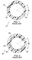
- aperture lamp 10 Two types of aperture lamps with internal slits are in general use.
- the first type is shown in cross section as aperture lamp 10 in Figure 1.
- the lamp is composed of a hollow glass tube 12 having a phosphor coating 14 on the entire inside surface except in one narrow region 16 subtending angle 18.
- the center of the tube is filled with a mixture of gases which, when excited by an electric current supplied by electrodes (not shown) at the ends of the tube, emits ultraviolet light.
- the ultraviolet light strikes the phosphor coating 14 and is converted to visible light.
- a typical phosphor coating is also a diffuse reflector.
- a diffuse reflector is a reflector that scatters incident light into a range of angles. Diffuse reflectors typically have high reflectivity only when the reflective coating is relatively thick (e.g. about 0.15 mm or greater).
- the reflective phosphor coating on the inside of an aperture lamp is, by necessity, significantly thinner than 0.15 mm resulting in poor reflectivity (on the order of 60-80%). Most of the light not reflected by the phosphor is transmitted through the coating. By placing an aperture, in this case gap 16, in the phosphor coating, light can be directed preferentially out the aperture. However, due to loss of some of the light through the phosphor coating, the effectiveness of this type of aperture lamp is significantly reduced.
- aperture lamp 50 A second type of lamp having an internal aperture and known to those skilled in the art is shown in Figure 2 as aperture lamp 50.
- the lamp has a glass tube 52. Inside the glass tube is a phosphor coating 54 and an additional reflective coating 56. There is an aperture opening 58 through both the phosphor coating 54 and reflective coating 56 which subtends angle 59 and which allows light to escape preferentially in one direction.
- the phosphor and reflective coatings must be very thin and the selection of coating materials is very limited so as not to interfere with the operation of the lamp. No organic materials are possible for an internal coating because any outgassing from the organic material or decomposition of the organic material from the effects of ultraviolet light would lower the efficiency of the lamp. Second, because of the restrictions on coating materials, the reflectivity of the coatings is not as high as desired. Third, a significant amount of ultraviolet light generated inside the lamp is wasted due to absorption by the glass tube in the area without the phosphor coating.
- the invention is as defined in claim 1.
- the present invention can be used in an improved linear illumination source.
- the linear illumination source comprises: (a) a linear light source having a width w 1 in a direction perpendicular to the long axis of the linear source, and (b) a external reflective enclosure partially surrounding the aforementioned linear light source, wherein the external reflective enclosure has a maximum inside width w 2 , and wherein the external reflective enclosure has at least one linear opening of maximum width w 3 such that (0.03)(w 2 ) ⁇ w 3 ⁇ (0.75)(w 2 ).
- a linear light source is defined as a light source having a length dimension that is at least three times the width dimension w 1 .
- a linear light source may be comprised of a single element or may be a linear array containing a multiplicity of elements. If the linear light source is an array containing a multiplicity of elements, then the length of the array is at least three times the width of an individual element.
- a linear opening is defined as an opening having a length dimension that is at least three times the width dimension.
- the invention can also be used in a linear illumination system which utilizes the aforementioned linear illumination source and one or more additional optical elements in order to achieve a system with high optical efficiency and high output irradiance and/or radiance.
- a linear illumination system comprises: (a) a linear light source having a width w 1 in a direction perpendicular to the long axis of the linear source, (b) an external reflective enclosure partially surrounding the aforementioned linear light source, wherein the external reflective enclosure has a maximum inside width w 2 , and wherein the external reflective enclosure has at least one linear opening of maximum width w 3 such that (0.03)(w 2 ) ⁇ w 3 ⁇ (0.75)(w 2 ), and (c) at least one optical element in close proximity to at least one linear opening.
- An optical element may include, for example, a cylindrical rod lens, a lenticular lens, an aspherical lenticular lens, a lenticular prism, an array of lenticular lenses, an array of lenticular prisms, a mirror, a reflecting concentrator, or a waveguide.
- lenticular we mean a linear optical element having the cross-section (in one direction only) of a lens or a prism.
- the invention comprises a unique housing that provides both optical and mechanical properties for the operation of an illumination device, and can be easily made using conventional manufacturing methods.
- the shapes consists of a hollow enclosure having sufficient diameter and length to encircle a linear fluorescent lamp acting as the source of light.
- the enclosure wall contains an aperture such that light can escape from within.
- the enclosure further contains at least one member such that it receives and holds an optical element of the assembly, typically a transparent, cylindrical rod lens.
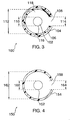
- a linear illumination source 100 is shown in cross-section in Figure 3.
- Linear illumination source 100 is comprised of linear light source 102 that is partially surrounded by an external enclosure 104.
- the linear light source 102 may be centered in the external enclosure 104 or displaced to one side of the enclosure.
- One or more linear openings 108 in the wall of the external enclosure allow light to escape from the enclosure.
- a reflective layer 106 In close proximity to the inside surface of the external enclosure 104 is a reflective layer 106.
- the width of the linear light source is 110
- the maximum inside width of the external enclosure is 112
- the maximum width of the linear opening is 114.
- the external enclosure 104 is constructed from a transparent material, the external enclosure may completely surround the linear light source 102.
- an opening 108 must still remain in the reflective layer 106 in order for light to escape from the linear illumination source.
- the linear light source 102 can be any source that emits light.
- Exemplary linear light sources include, but are not limited to, one or more of the following types of light sources: fluorescent lamps, light emitting diodes (LEDs), laser diodes, organic light emitting diodes, electroluminescent strips, or high-intensity discharge lamps.
- a multiplicity of light emitting diodes placed in a row is a linear light source.
- the single or multiple elements of the linear light source may emit light of one color, multiple colors, or white light (which is composed of multiple colors).
- the linear light source 102 illustrated in Figure 3 can emit light in all directions.
- a fluorescent lamp is an example of a linear light source 102 that emits light in all directions.
- it is preferable that linear light source 102 have a non-absorptive surface 116. Such a non-absorptive surface 116 may be reflective, transmissive or both.
- the gap 118 can act as an insulating layer which will allow the linear light source 102 to warm up quickly to its optimum operating temperature.
- the gap is greater than about 10 % of the width 110 of the linear light source.
- the external enclosure 104 shown in Figure 3 can have any cross-sectional shape including, but not limited to, circular, elliptical, oval, cusp-shaped, or faceted.
- the linear opening 108 preferably has a maximum width 114 that is less than the maximum inside width 112 of the external enclosure 104. More preferably, the maximum width 114 of linear opening 108 ranges from about 3 % to about 75 % of the maximum inside width 112 of the external enclosure. Most preferably, the maximum width 114 of linear opening 108 ranges from about 5 % to about 50% of the maximum inside width 112 of the external enclosure.
- linear light source 102 is a tubular fluorescent lamp
- the maximum width 114 of linear opening 108 ranges from about 10 % to about 100 % of the width 110 of the linear light source. More preferably, the width 114 of the linear opening 108 ranges from about 20 % to about 90 % of the width 110 of the linear light source.
- the width of the linear opening 108 may be uniform along the length of the linear light source or the width of linear opening 108 may vary along the length of the linear light source in order to change the output light distribution along the light source. This latter feature of the current invention provides a critical advantage for applications requiring a uniform illumination, whereby the nonuniformity inherent in the light output of the lamp can be corrected to give a uniform irradiance.
- the width of the aperture can be widened at any point along the length of the lamp where the lamp output is low in order to provide a relatively constant and uniform output from the illumination source.
- the reflective layer 106 may be constructed from any material that reflects light.
- the reflective layer may be a diffuse reflector, a specular reflector, or a combination of specular and diffuse reflectors.
- Diffuse reflectors can be made that have very high reflectivities (for example, greater than 95 % or greater than 98%). However, diffuse reflectors with high reflectivities are generally quite thick. For example, diffuse reflectors with reflectivities greater than 98 % are typically several millimeters thick. Examples of diffuse reflectors include, but are not limited to, fluoropolymer materials such as Spectralon TM from Labsphere, Inc. and polytetrafluoroethylene (PTFE) film from Fluorglas (sold under the trade name Furon TM ), W. L. Gore and Associates, Inc. (sold under the trade name DRP TM ), or E. I.
- fluoropolymer materials such as Spectralon TM from Labsphere, Inc. and polytetrafluoroethylene (PTFE) film from Fluorglas (sold under the trade name Furon TM ), W. L. Gore and Associates, Inc. (sold under the trade name DRP TM ), or E. I.
- du Pont de Nemours & Company sold under the trade name of Teflon TM
- films of barium sulfate porous polymer films containing tiny air channels such as polyethersulfone and polypropylene filter materials made by Pall Gelman Sciences
- polymer composites utilizing reflective filler materials such as, for example, titanium dioxide.
- An example of the latter material is titanium-dioxide-filled ABS (acrylonitrile-butadiene-styrene terpolymer) produced by RTP.
- a structural material is employed as a reflective material, such as titanium dioxide filled ABS
- the structural support 104 can be combined with the reflective layer 106 as shown in Figures 4 and 5.
- specular reflective materials have reflectivities ranging from about 80 % to about 93 %. Any light that is not reflected by the specular reflector is absorbed and converted to heat, thus lowering the efficiency of any optical system utilizing such a reflector.
- specular reflective materials include, but are not limited to, Silverlux TM , a product of 3M, and other carrier films of plastic which have been coated with a thin metallic layer such as silver, aluminum or gold. The thickness of the metallic coating may range from about 0.05 ⁇ m to about 0.1 mm, depending on the materials used and the method of manufacturing the metal coating.
- An example of a combination of specular and diffuse reflective materials is one or more layers of a diffuse reflector that is backed by a specular reflector.
- Such a combination of specular and diffuse reflective materials is disclosed in U.S. patent application 08/679,047 and is incorporated herein by reference.
- the use of a combination of specular and diffuse reflective materials may result in higher reflectivity in a thinner layer than is possible using a diffuse reflective material alone.
- the efficiency of illumination source 100 can be defined as the percentage of the light emitted from linear light source 102 that escapes through linear opening 108.
- the efficiency depends strongly on the width 114 of linear opening 108, the circumference of the inside surface of reflective layer 106, the reflectivity of the reflective layer 106 and the reflectivity of the linear light source 102. For example, if the width 114 of linear opening 108 is 1/10 of the circumference of the inside surface of reflective layer 106, then only 10% of the light that is emitted from linear light source 102 will escape through linear opening 108 without being reflected by reflective layer 106.
- the remaining 90% of the light will be reflected one or more times by reflective layer 106 or by the linear light source 102 before escaping from linear opening 108 or before being absorbed by the reflective surfaces and converted to heat. Some of the light may be reflected ten times or more before escaping. The large number of times that the light can be reflected makes it very important that the reflectivity of the reflecting layer 106 be as close to 100% as the practical considerations of space and cost will allow. For example, if the reflectivity of an optical surface is 90% per reflection and the light reflects ten times from that surface, the overall efficiency is (0.90) 10 or 35 %. The other 65 % of the light is lost.
- the reflectivity of the reflector is increased to 95 % per reflection and the light reflects ten times from that surface, the overall efficiency is (0.95) 10 or 60%, a significant improvement over 35 %. Greater improvements may be attained if the reflectivity is greater than 95 %.
- the reflectivity of the material employed for layer 106 is preferably greater than 90 %, more preferably greater than 95 %, and most preferably greater than about 97%.
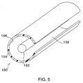
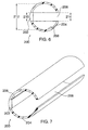
- a linear illumination source 150 is shown in Figure 4 (a cross-sectional view) and in Figure 5 (a perspective view).
- linear light source 152 having width 160 is partially surrounded by an external reflective enclosure 154 having a maximum inside width 162.
- One or more linear openings 158 in the wall of the external reflective enclosure 154 allow light to escape from the enclosure.
- the maximum width of the linear opening 158 is dimension 164.
- the external reflective enclosure 154 shown in Figures 4 and 5 can have any cross-sectional shape including, but not limited to, circular, elliptical, oval, cusp-shaped, or faceted.
- the linear opening 158 preferably has a maximum width 164 that is less than the maximum inside width 162 of the external reflective enclosure 154.
- the maximum width 164 of linear opening 158 ranges from about 3 % to about 75 % of the maximum inside width 162 of the external reflective enclosure. Most preferably, the maximum width 164 of linear opening 158 ranges from about 5% to about 50 % of the maximum inside width 162 of the external reflective enclosure. In addition, if linear light source 152 is a tubular fluorescent lamp, preferably the maximum width 164 of linear opening 158 ranges from about 10% to about 100% of the width 160 of the linear light source. More preferably, the width 164 of the linear opening 158 ranges from about 20 % to about 90 % of the width 160 of the linear light source. The width of the linear opening 158 may be uniform along the length of the linear light source or the width of linear opening 158 may vary along the length of the linear light source in order to change the output light distribution along the light source to compensate for non-uniformities in the light source.
- the embodiment shown in Figures 4 and 5 is similar to Figure 3 except that now the structural material of the external enclosure 154 is also the reflective material.
- This embodiment is especially useful if the structural material for the external reflective enclosure is a diffuse reflector. Examples of diffuse reflectors are listed above.
- the reflective material can be cut, formed, extruded, or molded into the required shape for the external reflective enclosure and, of course, possesses sufficient tensile modulus, flexual modulus, heat deflection temperature, and impact resistance to serve as the structural member for the illumination system.
- Preferred reflective materials for use in the particular embodiments 150, 200, 300, 350, 400, 450, and 500 are engineering thermoplastics which have been filled with fine particles which have an index of refraction which is substantially greater than that of the host polymer and are optically clear or white in their neat form, such as titanium dioxide (rutile and anatase), aluminum oxide, zinc oxide, zinc sulfide, barium sulfate, antimony oxide, magnesium oxide, calcium carbonate, strontium titantate, and the like.
- Preferred materials also include engineering thermoplastics which contain particles, voids or gas-filled bubbles created, for example, by foaming, and whereby the particles, voids or bubbles possess an index of refraction substantially less than that of the host polymer.
- the filler particles or voids preferably lie in the size range from about 0.1 microns to about 3.0 microns and most preferably from about 0.1 microns to about 1 microns.
- Thermoplastics useful in this invention are preferably non-yellow and include a wide variety of plastics known in the art to be useful for injection molding or extrusion, such as, for example, ABS, poly (methyl methacrylate) poly(ethylene terephthalate) (PET), poly(butylene terephthalate) (PBT), polypropylene, nylon 6, nylon 66, polycarbonate, polystyrene, poly(phenylene oxide), and blends and alloys thereof.
- ABS poly (methyl methacrylate) poly(ethylene terephthalate) (PET), poly(butylene terephthalate) (PBT), polypropylene, nylon 6, nylon 66, polycarbonate, polystyrene, poly(phenylene oxide), and blends and alloys thereof.
- Linear illumination source 200 is shown in Figure 6 (a cross-sectional view) and Figure 7 (a perspective view).
- the linear light source 202 having width 210 is embedded into the side of the external reflective enclosure 204 which has a maximum inside width 212.
- One or more linear openings 208 in the wall of the external reflective enclosure 204 allow light to escape from the enclosure.
- the maximum width of each linear opening 208 is dimension 214.
- the linear opening 208 is illustrated to be on the side of the external reflective enclosure 204 opposite the linear light source 202. However, this is not required and the linear light source 202 and the linear opening 208 may be adjacent to each other.
- the external reflective enclosure 206 may be constructed from a diffuse reflective material or an additional reflective layer may be placed on the inner surface 206 of external reflective enclosure 204 in order to achieve high reflectivity.
- the linear light source 202 illustrated in Figures 6 and 7 preferably emits light into a hemisphere (a solid angle of 2 ⁇ ) or into a solid angle less than 2 ⁇ and preferably does not emit light in all directions (which would be a solid angle of 4 ⁇ ). Examples of linear light source 202 include, but are not limited to, light emitting diodes, laser diodes, organic light emitting diodes, and electroluminescent strips.
- the external reflective enclosure 204 can also serve to homogenize the light output from the linear light source 202.
- the linear light source 202 is an array of light emitting diodes, laser diodes, or organic light emitting diodes, each of which may have a very small light emitting surface. If the linear light source 202 includes elements that emit different colors (for example, red, green and blue light emitting diodes), the external reflective enclosure 204 can mix the colors to form a white light output.
- the linear light source 202 includes elements that emit different colors (for example, red, green and blue light emitting diodes)
- the external reflective enclosure 204 can mix the colors to form a white light output.
- Linear illumination source 250 is shown in cross-section in Figure 8. This configuration is especially useful if the linear light source is, for example, a tubular fluorescent lamp which is illustrated in Figure 8 as a transparent glass envelope 252 that is coated on the inside with a phosphor layer 254.
- the linear light source is surrounded by external enclosure 256 except for opening 264 having an opening width 262.
- the external enclosure 256 may be constructed from a reflective material, a non-reflective material, or a transparent material. If the external enclosure is constructed from a non-reflective or transparent material, an additional reflective layer 258 is needed on the inside surface of external enclosure 256.
- the reflective structure or structures may be constructed from diffuse reflective materials, specular reflective materials, or a combination of diffuse reflective materials and specular reflective materials. Examples of diffuse and specular reflective materials are listed above.
- Figure 8 is similar to Figure 3 except that in Figure 8 there is little or no gap between the linear light source and the reflecting layer 258. In the preferred embodiment, the gap is less than 10% of the lamp width 260. If the linear light source is a fluorescent lamp, removing the gap can lead to higher output efficiency of the linear illumination source by decreasing the number of times the light must reflect inside the external reflective enclosure before is escapes from opening 264.
- fluorescent lamps are very sensitive to the temperature of their surroundings. Placing the external enclosure 256 and/or the reflective layer 258 in close proximity or actual contact with the fluorescent lamp may lengthen the warm-up time of the lamp with resulting reduced light output while the lamp is warmthing up, or may lower the steady-state operating temperature of the fluorescent lamp which again could result in lower light output.
- the external enclosure 256 may completely surround the glass envelope 252 of the fluorescent lamp. However, an opening 264 must still remain in reflective layer 258 in order for light to escape from the linear illumination source.
- An example of the optional configuration would be to use a flexible, diffuse, reflective layer 258 having an opening 264 and to use transparent shrink tubing for the external enclosure 256. After the pieces are assembled into the correct configuration, the shrink tubing can be heated causing it to shrink tightly around the reflector and fluorescent lamp.
- linear illumination sources of the type illustrated in Figures 3-8 may include additional optical elements such as, for example, waveguides, cylindrical rod lenses, lenticular lenses, aspherical lenticular lenses, arrays of lenticular lenses, prisms, arrays of lenticular prisms, reflectors, concentrators and collimators.
- the optical elements may be used to shape, focus, collimate, or project the light being emitted from the linear illumination source. Examples of such illumination systems are illustrated in Figures 9-14 and are not meant to limit the scope of this invention. Note, for example, that any of the linear illumination sources illustrated in Figures 3-8 may be used with any of the optical elements in order to make additional linear illumination systems.
- the additional optical elements may also be used in combination, such as the lens of Figure 10 together with the light guide of Figure 9, or a lens and CPC can be integrated together, or multi-stage CPC's in series may be employed.
- linear illumination system 300 which is comprised of a linear illumination source 320 and optical waveguide 316.
- linear illumination source 320 is illustrated to be of the type shown previously in Figure 4 and is further comprised of a linear light source 302 and a external reflective enclosure 304.
- a linear opening 308 in external reflective enclosure 304 allows light to pass from the linear illumination source 320 to an optical waveguide 316.
- the optical waveguide may be used to transport the light by total internal reflection (TIR) to places remote from the linear illumination source 320.
- TIR total internal reflection
- other optical components may be used with optical waveguide 316 to form additional illumination systems. Applications for such linear illumination systems include edge-lit illumination systems for flat panel displays and collimating illumination systems.
- linear illumination system 350 Illustrated in Figure 10 (a cross-sectional view) and Figure 11 (a perspective view) is linear illumination system 350, which is comprised of linear illumination source 370 and a lens 366.
- linear illumination source 370 is illustrated to be of the type shown previously in Figure 4.
- a linear opening 358 in the external reflective enclosure 354 allows light to pass from the linear illumination source 370 to the lens 366.
- linear opening 358 has a maximum width 364 that is less than the maximum inside width 362 of the external reflective enclosure 354. More preferably, the maximum width 364 of the linear opening 358 ranges from about 3 % to about 75 % of the maximum inside width 362 of the external reflective enclosure.
- the maximum width 364 of linear opening 358 ranges from about 5 % to about 50 % of the maximum inside width 362 of the external reflective enclosure.
- the maximum width 364 of the linear opening 358 ranges from about 5 % to about 100 % of the width 360 of the linear light source 352. More preferably, the width 364 of the linear opening 358 ranges from about 20% to about 90% of the width 360 of the linear light source.
- lens 366 examples include, but are not limited to, a lenticular lens, an aspherical lenticular lens, a cylindrical rod lens, a plano-convex lenticular lens, a double-convex lenticular lens, a lenticular Fresnel lens, and multi-element lenses of any type.
- linear illumination systems in which the lens 366 is a cylindrical rod lens as is illustrated in Figures 10 and 11.
- Lens 366 may be constructed from any transparent material. Linear illumination systems may be used in many applications including, for example, optical scanners, facsimile machines, and photocopiers.
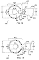
- Figure 12 illustrates linear illumination system 400, which is comprised of linear illumination source 430 and a transparent optical element 416.
- the linear illumination source 430 is illustrated to be of the type shown in Figure 4 and is, in turn, comprised of linear light source 402 and external reflective enclosure 404.
- External reflective enclosure 404 has a linear opening 408 with a maximum width 414 that allows light to pass from the linear illumination source 430 to the transparent optical element 416.
- Transparent optical element 416 has an input surface 418 adjacent to opening 408, a tapered section of length 432 bounded by sidewalls 420 and 422, and an output surface 424.
- transparent optical element 416 also includes a straight section with parallel sidewalls 434 and 436, whereby the straight section is positioned between the tapered section (bounded by the sidewalls 420 and 422) and the output surface 424.
- the input surface 418 is planar but planarity is not required.
- the output width 428 of the optical element 416 is preferably greater than the input width 426 of the tapered section. More preferably, the output width 428 of the optical element 416 is at least two times the input width 426.
- the sidewalls 420 and 422 of the tapered section may be planar, curved, or faceted.
- the output surface 424 of the transparent optical element 416 may also be planar, curved, or faceted.
- the output surface 424 is a curved lenticular lens, whereby the lens may have a single radius of curvature, may be parabolic in shape, or may have some general shape having no single radius of curvature. More preferably, output surface 424 has a single radius of curvature R, where the radius of curvature R may range from one-half of the output width 428 to about 1.5 times one-half of the output width 428. In other words, the range of the radius of curvature R is ( width 428 ) / 2 ⁇ R ⁇ ( 1.5 ) ( width 428 ) / 2 . Light enters transparent optical element 416 through input surface 418.
- the reflections may occur by TIR if the sidewalls 420, 422, 434, and 436 are uncoated or may occur by normal reflection if the sidewalls are coated with a reflective coating. Since the sidewalls 420 and 422 form an expanding taper, the light will be partially collimated by the tapered section of the optical element 416.
- the light then exits through the output surface 424 which can further shape the output light beam.
- Output surface 424 may result in a light output beam that is either more collimated or more focused.
- FIG 13 illustrates linear illumination system 450, which is comprised of an illumination source 476 and a tapered optical structure 466.
- linear illumination source 476 is illustrated to be of the type shown in Figure 4.
- the illumination source 476 is further comprised of a linear light source 452 and an external reflective enclosure 454.
- An opening 458 in the external reflective enclosure 454 allows light to pass from the illumination source 452 to the tapered optical structure 466 having sidewalls 470 and 472.
- the tapered optical structure 466 is a solid structure (not hollow), preferably the light input end 468 of tapered optical structure 466 is a planar surface, but planarity is not required.
- the output width 480 of tapered optical structure 466 is greater than the input width 478.
- the output width 480 of the tapered optical structure 466 is at least two times the input width 478.
- linear illumination systems in which the sidewalls 470 and 472 of the tapered optical waveguide have a parabolic shape or the shape of a compound parabolic concentrator (CPC).
- the tapered optical structure 466 may be constructed from a solid transparent material having surfaces 470 and 472 that are either uncoated or coated with a reflective material or the tapered optical structure 466 may be a hollow structure with surfaces 470 and 472 coated with a reflective material and with open ends 468 and 474. Light enters the tapered optical structure 466 at input end 468, reflects from surfaces 470 and 472 and exits at output end 474.
- the light at the output end 474 of the taper is more collimated than the light at the input end 468.
- the optical structure 466 is fabricated from a clear dielectric material, it is also possible to make the output end 474 not planar as shown but convex. In such a case, a given degree of collimation can be achieved with an element of shorter length, where length is defined as the perpendicular distance from input end 468 to the output end 474.
- Figure 14 shows linear illumination system 500.
- Linear illumination system 500 is comprised of linear illumination source 520 and an array 516 of lenticular optical elements 518.
- linear illumination source 520 is illustrated to be of the type shown in Figure 4.
- Linear illumination source 520 is further comprised of linear light source 502 which is partially surrounded by external reflective enclosure 504 with opening 508.
- the lenticular optical elements 518 may include lenticular prisms and lenticular lenses used separately or in combination. If the lenticular optical elements 518 are lenticular prisms, the sidewalls of the prisms may be planar, curved or faceted.
- the lenticular optical elements 518 are lenticular lenses
- the lenses may have one radius of curvature, multiple radii of curvature, or may be aspherical lenticular lenses.
- the purpose of the array 516 of lenticular optical elements is to further shape or collimate or focus the light emerging from opening 508.
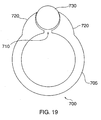
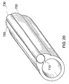
- Housing system 700 is comprised of a hollow linear enclosure 705 having sufficient diameter and length to encircle a linear light source, such as for example a fluorescent lamp.
- the wall of the enclosure tube has a linear aperture 710 so that light can escape from within.
- the aperture 710 is typically in the form of a slit of controlled which extends the length of the enclosure parallel to its axis.
- the maximum width of the linear aperture 710 is less than the maximum inside width of the linear enclosure 705.
- the maximum width of the linear aperture 710 ranges from about 3 % to about 75% of the maximum inside width of the linear enclusre 705. More preferably, the maximum width of the linear aperture 710 ranges from about 5% to about 50 % of the maximum inside width of the inear enclosure 705.
- the contour of the linear enclosure's cross section in the vicinity of the aperture is shaped such that it has at least one member 720 which makes multiple line contact with an optical element 730 of the assembly.
- This optical element 730 is typically a transparent, cylindrical rod having a diameter larger than the width of the slit and smaller than the diameter of the enclosure. The rod serves to alter the direction of the light passing through it from its initial direction emanating from the slit.
- At least one member 720 of the enclosure has a cross sectional contour designed to hold the rod 730 securely against the enclosure in a fixed position while not interfering with the desired passage of light from within the enclosure , and through the slit 710 and rod 730.
- the enclosure and rod may be assembled so that by exertion of physical force on the rod against the contoured members causes the members to expand and receive the rod such the the rod is held and makes line contact along its length with the enclosure. In this manner no additional elements or adhesives are necessary to hold the rod onto the enclosure.
- the hollow enclosure containing the slit has two integrated contoured members for holding the rod element which are fabricated using conventional extrusion techniques.
- the enclosure is preferably linear and made from a reflecting material having a reflectivity of 95 % or higher so that no additional reflecting elements such as reflecting films or coatings are needed.
- this invention is applicable to a wide variety of devices requiring linear illumination sources and linear illumination systems. Examples include, but are not limited to: scanners, facsimile machines, photocopiers and direct illumination devices for commercial, office, residential, outdoor, automotive, and appliance applications.
- the invention herein may also be applied to displays (e.g. flat panel displays) for computer, automotive, military, aerospace, consumer, commercial, and industrial applications.
Description
- The present invention relates specifically to a linear light source in a single, manufacturable part and more generally, to high-efficiency, linear illumination sources and linear illumination systems which have enhanced output irradiance and radiance. Irradiance is defined as the light flux per unit area and can be expressed, for example, in units of watts per square centimeter (W/cm2). Radiance is the brightness of the light. Radiance can be expressed, for example, in units of watts per square centimeter per steradian (W/(cm2•steradian), where a steradian is the unit of solid angle.
- For many applications, an illumination source with a narrow output opening and high output efficiency is preferred. Such a source is commonly constructed using an aperture lamp with an internal slit aperture built into the lamp structure. However, an aperture lamp generally has lower light emission than a conventional lamp due to increased light absorption inside the lamp and due to a reduction in the surface area of the phosphor coating. It would be highly desirable to have an improved narrow illumination source that is more efficient than a lamp with an internal slit aperture.
- For applications such as, for example, optical scanners and photocopiers, a linear illumination system with high output irradiance is desired in order to illuminate a narrow strip of the area being scanned or photocopied. The illumination assembly for such a device commonly consists of a bare linear light source, an aperture lamp, or a lamp partially surrounded with a specular reflector. A specular reflector is a mirror-like reflector with a smooth surface and has the property that the angle of light incidence equals the angle of reflection, where the incident and reflection angles are measured relative to the direction normal to the surface. An improved linear illumination system which has higher output irradiance would be advantageous.
- For certain other applications such as flat panel displays, an illumination system having a very shallow thickness is highly desirable. Such systems are commonly configured with one or more illumination sources, a waveguide or light pipe for collecting and distributing the light from the illumination sources, and additional scattering, reflecting, or collimating elements for extracting the light from the waveguide. A significant depth savings can be achieved by coupling the illumination sources through the edge of the waveguide. The amount of light extracted from the system is proportional to the number of reflections or scattering events that occur within the waveguide, the number being inversely proportional to the thickness of the waveguide. To obtain maximum light output, a thin waveguide is preferable. However, this results in waveguide edges having a small surface area, limiting the size of the illumination source that can directly adjoin the edge of the waveguide. On the other hand, if the surface area of the waveguide edge is increased, the extraction efficiency of the waveguide will decrease. It would be highly desirable to utilize a thin waveguide yet provide the maximum illumination source input. Therefore, a highly-efficient, linear illumination source with high output irradiance and radiance from a narrow opening is needed.
- It is well-known that it is possible to use tubular fluorescent lamps having an internal slit aperture in order to concentrate and direct the emitted light into a narrow angular range. Two types of aperture lamps with internal slits are in general use. The first type is shown in cross section as
aperture lamp 10 in Figure 1. The lamp is composed of ahollow glass tube 12 having a phosphor coating 14 on the entire inside surface except in onenarrow region 16subtending angle 18. The center of the tube is filled with a mixture of gases which, when excited by an electric current supplied by electrodes (not shown) at the ends of the tube, emits ultraviolet light. The ultraviolet light, in turn, strikes the phosphor coating 14 and is converted to visible light. A typical phosphor coating is also a diffuse reflector. Note that a diffuse reflector is a reflector that scatters incident light into a range of angles. Diffuse reflectors typically have high reflectivity only when the reflective coating is relatively thick (e.g. about 0.15 mm or greater). The reflective phosphor coating on the inside of an aperture lamp is, by necessity, significantly thinner than 0.15 mm resulting in poor reflectivity (on the order of 60-80%). Most of the light not reflected by the phosphor is transmitted through the coating. By placing an aperture, in thiscase gap 16, in the phosphor coating, light can be directed preferentially out the aperture. However, due to loss of some of the light through the phosphor coating, the effectiveness of this type of aperture lamp is significantly reduced. - A second type of lamp having an internal aperture and known to those skilled in the art is shown in Figure 2 as
aperture lamp 50. The lamp has aglass tube 52. Inside the glass tube is aphosphor coating 54 and an additionalreflective coating 56. There is an aperture opening 58 through both thephosphor coating 54 andreflective coating 56 which subtendsangle 59 and which allows light to escape preferentially in one direction. - There are six significant problems associated with the
internal aperture lamps - Accordingly, there are now provided with this invention improved linear illumination sources which utilize external, highly reflective enclosures incorporating one or more linear openings in order to achieve improved source efficiency, output irradiance and output radiance. Such improved illumination sources may be combined with additional optical elements to produce more complex illumination systems. Additional objects of the present invention will become apparent from the following description.
- The invention is as defined in
claim 1. The present invention can be used in an improved linear illumination source. The linear illumination source comprises: (a) a linear light source having a width w1 in a direction perpendicular to the long axis of the linear source, and (b) a external reflective enclosure partially surrounding the aforementioned linear light source, wherein the external reflective enclosure has a maximum inside width w2, and wherein the external reflective enclosure has at least one linear opening of maximum width w3 such that (0.03)(w2) ≤ w3 ≤ (0.75)(w2). A linear light source is defined as a light source having a length dimension that is at least three times the width dimension w1. A linear light source may be comprised of a single element or may be a linear array containing a multiplicity of elements. If the linear light source is an array containing a multiplicity of elements, then the length of the array is at least three times the width of an individual element. A linear opening is defined as an opening having a length dimension that is at least three times the width dimension. - The invention can also be used in a linear illumination system which utilizes the aforementioned linear illumination source and one or more additional optical elements in order to achieve a system with high optical efficiency and high output irradiance and/or radiance. Such a linear illumination system comprises: (a) a linear light source having a width w1 in a direction perpendicular to the long axis of the linear source, (b) an external reflective enclosure partially surrounding the aforementioned linear light source, wherein the external reflective enclosure has a maximum inside width w2, and wherein the external reflective enclosure has at least one linear opening of maximum width w3 such that (0.03)(w2) ≤ w3 ≤ (0.75)(w2), and (c) at least one optical element in close proximity to at least one linear opening. An optical element may include, for example, a cylindrical rod lens, a lenticular lens, an aspherical lenticular lens, a lenticular prism, an array of lenticular lenses, an array of lenticular prisms, a mirror, a reflecting concentrator, or a waveguide. By lenticular, we mean a linear optical element having the cross-section (in one direction only) of a lens or a prism.
- The invention comprises a unique housing that provides both optical and mechanical properties for the operation of an illumination device, and can be easily made using conventional manufacturing methods. The shapes consists of a hollow enclosure having sufficient diameter and length to encircle a linear fluorescent lamp acting as the source of light. The enclosure wall contains an aperture such that light can escape from within. The enclosure further contains at least one member such that it receives and holds an optical element of the assembly, typically a transparent, cylindrical rod lens.
- The embodiments of the present invention will be better understood by reference to the following detailed discussions of specific embodiments and the attached figures which illustrate and exemplify such embodiments.
- The invention will be more fully understood and further advantages will become apparent when reference is made to the following detailed description of the invention and the accompanying drawings in which:
- Figure 1 is a schematic cross-sectional diagram of an internal aperture lamp of the prior art;
- Figure 2 is a schematic cross-sectional diagram of an alternative internal aperture lamp of the prior art;
- Figure 3 is a schematic cross-sectional diagram of a linear illumination source;
- Figures 4 and 5 are respectively, schematic cross-sectional and perspective diagrams of an alternative version of a linear illumination source;
- Figures 6 and 7 are respectively, schematic cross-sectional and perspective diagrams of another version of a linear illumination source;
- Figure 8 is a schematic cross-sectional diagram of another linear illumination source;
- Figure 9 is a schematic cross-sectional diagram of a linear illumination system utilizing the linear illumination source of Figure 4 and a waveguide;
- Figures 10 and 11 are, respectively, schematic cross-sectional and perspective diagrams of a linear illumination system utilizing the linear illumination source of Figure 4 and a lens;
- Figure 12 is a schematic cross-sectional diagram of a linear illumination system utilizing the linear illumination source of Figure 4 and a lens that functions both by refraction and total internal reflection;
- Figure 13 is a schematic cross-sectional diagram of a linear illumination system utilizing the linear illumination source of Figure 4 and a compound parabolic concentrator (CPC); and
- Figure 14 is a schematic cross-sectional diagram of a linear illumination system utilizing the linear illumination source of Figure 4 and an array of optical elements.
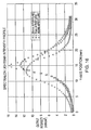
- Figure 15 is a plot of intensity (irradiance) versus detector position.
- Figure 16 is a plot of intensity (irradiance) versus detector position.
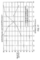
- Figure 17 is a plot of relative output versus opening width.
- Figure 18 is a plot of intensity (irradiance) versus detector position.
- Figure 19 is a schematic cross-sectional diagram of an embodiment of the novel housing of the present invention
- Figure 20 is another view of the novel housing of an embodiment of the present invention.
- The following preferred embodiments as exemplified by the drawings are illustrative of the invention and are not intended to limit the scope of the invention as encompassed by the claims of this application. Illumination sources and illumination systems using improved external reflective enclosures, linear openings and, optionally, additional optical elements are disclosed herein.
- A
linear illumination source 100 is shown in cross-section in Figure 3.Linear illumination source 100 is comprised of linearlight source 102 that is partially surrounded by anexternal enclosure 104. The linearlight source 102 may be centered in theexternal enclosure 104 or displaced to one side of the enclosure. One or morelinear openings 108 in the wall of the external enclosure allow light to escape from the enclosure. In close proximity to the inside surface of theexternal enclosure 104 is areflective layer 106. In this figure, the width of the linear light source is 110, the maximum inside width of the external enclosure is 112, and the maximum width of the linear opening is 114. Optionally, if theexternal enclosure 104 is constructed from a transparent material, the external enclosure may completely surround the linearlight source 102. However, anopening 108 must still remain in thereflective layer 106 in order for light to escape from the linear illumination source. - The linear
light source 102 can be any source that emits light. Exemplary linear light sources include, but are not limited to, one or more of the following types of light sources: fluorescent lamps, light emitting diodes (LEDs), laser diodes, organic light emitting diodes, electroluminescent strips, or high-intensity discharge lamps. As an illustrative example, a multiplicity of light emitting diodes placed in a row is a linear light source. The single or multiple elements of the linear light source may emit light of one color, multiple colors, or white light (which is composed of multiple colors). The linearlight source 102 illustrated in Figure 3 can emit light in all directions. A fluorescent lamp is an example of a linearlight source 102 that emits light in all directions. In order to maximize the efficiency of thelinear illumination system 100, it is preferable that linearlight source 102 have anon-absorptive surface 116. Such anon-absorptive surface 116 may be reflective, transmissive or both. - There is a
gap 118 between thesurface 116 of the linearlight source 102 and thereflective layer 106. Having a gap between linearlight source 102 and thereflective layer 106 is critical if the linearlight source 102 is a fluorescent lamp or other type of lamp where the magnitude of the light output of the lamp is sensitive to the lamp temperature. Thegap 118 can act as an insulating layer which will allow the linearlight source 102 to warm up quickly to its optimum operating temperature. Preferably the gap is greater than about 10 % of thewidth 110 of the linear light source. - The
external enclosure 104 shown in Figure 3 can have any cross-sectional shape including, but not limited to, circular, elliptical, oval, cusp-shaped, or faceted. Thelinear opening 108 preferably has amaximum width 114 that is less than the maximum insidewidth 112 of theexternal enclosure 104. More preferably, themaximum width 114 oflinear opening 108 ranges from about 3 % to about 75 % of the maximum insidewidth 112 of the external enclosure. Most preferably, themaximum width 114 oflinear opening 108 ranges from about 5 % to about 50% of the maximum insidewidth 112 of the external enclosure. In addition, if linearlight source 102 is a tubular fluorescent lamp, preferably themaximum width 114 oflinear opening 108 ranges from about 10 % to about 100 % of thewidth 110 of the linear light source. More preferably, thewidth 114 of thelinear opening 108 ranges from about 20 % to about 90 % of thewidth 110 of the linear light source. The width of thelinear opening 108 may be uniform along the length of the linear light source or the width oflinear opening 108 may vary along the length of the linear light source in order to change the output light distribution along the light source. This latter feature of the current invention provides a critical advantage for applications requiring a uniform illumination, whereby the nonuniformity inherent in the light output of the lamp can be corrected to give a uniform irradiance. The width of the aperture can be widened at any point along the length of the lamp where the lamp output is low in order to provide a relatively constant and uniform output from the illumination source. - The
reflective layer 106 may be constructed from any material that reflects light. The reflective layer may be a diffuse reflector, a specular reflector, or a combination of specular and diffuse reflectors. - Diffuse reflectors can be made that have very high reflectivities (for example, greater than 95 % or greater than 98%). However, diffuse reflectors with high reflectivities are generally quite thick. For example, diffuse reflectors with reflectivities greater than 98 % are typically several millimeters thick. Examples of diffuse reflectors include, but are not limited to, fluoropolymer materials such as Spectralon™ from Labsphere, Inc. and polytetrafluoroethylene (PTFE) film from Fluorglas (sold under the trade name Furon™), W. L. Gore and Associates, Inc. (sold under the trade name DRP™), or E. I. du Pont de Nemours & Company (sold under the trade name of Teflon™), films of barium sulfate, porous polymer films containing tiny air channels such as polyethersulfone and polypropylene filter materials made by Pall Gelman Sciences, and polymer composites utilizing reflective filler materials such as, for example, titanium dioxide. An example of the latter material is titanium-dioxide-filled ABS (acrylonitrile-butadiene-styrene terpolymer) produced by RTP. In the case that a structural material is employed as a reflective material, such as titanium dioxide filled ABS, the
structural support 104 can be combined with thereflective layer 106 as shown in Figures 4 and 5. - Most specular reflective materials have reflectivities ranging from about 80 % to about 93 %. Any light that is not reflected by the specular reflector is absorbed and converted to heat, thus lowering the efficiency of any optical system utilizing such a reflector. Examples of specular reflective materials include, but are not limited to, Silverlux™, a product of 3M, and other carrier films of plastic which have been coated with a thin metallic layer such as silver, aluminum or gold. The thickness of the metallic coating may range from about 0.05 µm to about 0.1 mm, depending on the materials used and the method of manufacturing the metal coating.
- An example of a combination of specular and diffuse reflective materials is one or more layers of a diffuse reflector that is backed by a specular reflector. Such a combination of specular and diffuse reflective materials is disclosed in U.S. patent application 08/679,047 and is incorporated herein by reference. The use of a combination of specular and diffuse reflective materials may result in higher reflectivity in a thinner layer than is possible using a diffuse reflective material alone.
- The efficiency of
illumination source 100 can be defined as the percentage of the light emitted from linearlight source 102 that escapes throughlinear opening 108. The efficiency depends strongly on thewidth 114 oflinear opening 108, the circumference of the inside surface ofreflective layer 106, the reflectivity of thereflective layer 106 and the reflectivity of the linearlight source 102. For example, if thewidth 114 oflinear opening 108 is 1/10 of the circumference of the inside surface ofreflective layer 106, then only 10% of the light that is emitted from linearlight source 102 will escape throughlinear opening 108 without being reflected byreflective layer 106. The remaining 90% of the light will be reflected one or more times byreflective layer 106 or by the linearlight source 102 before escaping fromlinear opening 108 or before being absorbed by the reflective surfaces and converted to heat. Some of the light may be reflected ten times or more before escaping. The large number of times that the light can be reflected makes it very important that the reflectivity of the reflectinglayer 106 be as close to 100% as the practical considerations of space and cost will allow. For example, if the reflectivity of an optical surface is 90% per reflection and the light reflects ten times from that surface, the overall efficiency is (0.90)10 or 35 %. The other 65 % of the light is lost. However, if the reflectivity of the reflector is increased to 95 % per reflection and the light reflects ten times from that surface, the overall efficiency is (0.95)10 or 60%, a significant improvement over 35 %. Greater improvements may be attained if the reflectivity is greater than 95 %. Thus, for the present invention, the reflectivity of the material employed forlayer 106 is preferably greater than 90 %, more preferably greater than 95 %, and most preferably greater than about 97%. - A
linear illumination source 150 is shown in Figure 4 (a cross-sectional view) and in Figure 5 (a perspective view). In this embodiment, linearlight source 152 havingwidth 160 is partially surrounded by an externalreflective enclosure 154 having a maximum insidewidth 162. One or morelinear openings 158 in the wall of the externalreflective enclosure 154 allow light to escape from the enclosure. The maximum width of thelinear opening 158 isdimension 164. The externalreflective enclosure 154 shown in Figures 4 and 5 can have any cross-sectional shape including, but not limited to, circular, elliptical, oval, cusp-shaped, or faceted. Thelinear opening 158 preferably has amaximum width 164 that is less than the maximum insidewidth 162 of the externalreflective enclosure 154. More preferably, themaximum width 164 oflinear opening 158 ranges from about 3 % to about 75 % of the maximum insidewidth 162 of the external reflective enclosure. Most preferably, themaximum width 164 oflinear opening 158 ranges from about 5% to about 50 % of the maximum insidewidth 162 of the external reflective enclosure. In addition, if linearlight source 152 is a tubular fluorescent lamp, preferably themaximum width 164 oflinear opening 158 ranges from about 10% to about 100% of thewidth 160 of the linear light source. More preferably, thewidth 164 of thelinear opening 158 ranges from about 20 % to about 90 % of thewidth 160 of the linear light source. The width of thelinear opening 158 may be uniform along the length of the linear light source or the width oflinear opening 158 may vary along the length of the linear light source in order to change the output light distribution along the light source to compensate for non-uniformities in the light source. - The embodiment shown in Figures 4 and 5 is similar to Figure 3 except that now the structural material of the
external enclosure 154 is also the reflective material. This embodiment is especially useful if the structural material for the external reflective enclosure is a diffuse reflector. Examples of diffuse reflectors are listed above. Preferably the reflective material can be cut, formed, extruded, or molded into the required shape for the external reflective enclosure and, of course, possesses sufficient tensile modulus, flexual modulus, heat deflection temperature, and impact resistance to serve as the structural member for the illumination system. - Preferred reflective materials for use in the
particular embodiments nylon 6, nylon 66, polycarbonate, polystyrene, poly(phenylene oxide), and blends and alloys thereof. -
Linear illumination source 200 is shown in Figure 6 (a cross-sectional view) and Figure 7 (a perspective view). In this embodiment, the linearlight source 202 havingwidth 210 is embedded into the side of the externalreflective enclosure 204 which has a maximum insidewidth 212. One or morelinear openings 208 in the wall of the externalreflective enclosure 204 allow light to escape from the enclosure. The maximum width of eachlinear opening 208 isdimension 214. In Figures 6 and 7, thelinear opening 208 is illustrated to be on the side of the externalreflective enclosure 204 opposite the linearlight source 202. However, this is not required and the linearlight source 202 and thelinear opening 208 may be adjacent to each other. The externalreflective enclosure 206 may be constructed from a diffuse reflective material or an additional reflective layer may be placed on theinner surface 206 of externalreflective enclosure 204 in order to achieve high reflectivity. The linearlight source 202 illustrated in Figures 6 and 7 preferably emits light into a hemisphere (a solid angle of 2π) or into a solid angle less than 2π and preferably does not emit light in all directions (which would be a solid angle of 4π). Examples of linearlight source 202 include, but are not limited to, light emitting diodes, laser diodes, organic light emitting diodes, and electroluminescent strips. In this embodiment of the invention, the externalreflective enclosure 204 can also serve to homogenize the light output from the linearlight source 202. This homogenization is especially important if the linearlight source 202 is an array of light emitting diodes, laser diodes, or organic light emitting diodes, each of which may have a very small light emitting surface. If the linearlight source 202 includes elements that emit different colors (for example, red, green and blue light emitting diodes), the externalreflective enclosure 204 can mix the colors to form a white light output. -
Linear illumination source 250 is shown in cross-section in Figure 8. This configuration is especially useful if the linear light source is, for example, a tubular fluorescent lamp which is illustrated in Figure 8 as atransparent glass envelope 252 that is coated on the inside with aphosphor layer 254. The linear light source is surrounded byexternal enclosure 256 except for opening 264 having anopening width 262. Theexternal enclosure 256 may be constructed from a reflective material, a non-reflective material, or a transparent material. If the external enclosure is constructed from a non-reflective or transparent material, an additionalreflective layer 258 is needed on the inside surface ofexternal enclosure 256. The reflective structure or structures, includingexternal enclosure 256 and/or reflectinglayer 258, may be constructed from diffuse reflective materials, specular reflective materials, or a combination of diffuse reflective materials and specular reflective materials. Examples of diffuse and specular reflective materials are listed above. Figure 8 is similar to Figure 3 except that in Figure 8 there is little or no gap between the linear light source and the reflectinglayer 258. In the preferred embodiment, the gap is less than 10% of thelamp width 260. If the linear light source is a fluorescent lamp, removing the gap can lead to higher output efficiency of the linear illumination source by decreasing the number of times the light must reflect inside the external reflective enclosure before is escapes from opening 264. (Note that the phosphor coating inside a fluorescent lamp typically has a reflectivity of approximately 60-80 % with most of the remainder of the light being transmitted so that it is possible for light to travel from one side of the lamp to the other by passing through the phosphor coating.) However, fluorescent lamps are very sensitive to the temperature of their surroundings. Placing theexternal enclosure 256 and/or thereflective layer 258 in close proximity or actual contact with the fluorescent lamp may lengthen the warm-up time of the lamp with resulting reduced light output while the lamp is wanning up, or may lower the steady-state operating temperature of the fluorescent lamp which again could result in lower light output. Optionally, if theexternal enclosure 256 is constructed from a transparent material and areflective layer 258 is utilized, theexternal enclosure 256 may completely surround theglass envelope 252 of the fluorescent lamp. However, anopening 264 must still remain inreflective layer 258 in order for light to escape from the linear illumination source. An example of the optional configuration would be to use a flexible, diffuse,reflective layer 258 having anopening 264 and to use transparent shrink tubing for theexternal enclosure 256. After the pieces are assembled into the correct configuration, the shrink tubing can be heated causing it to shrink tightly around the reflector and fluorescent lamp. - Other embodiments of this invention involve using linear illumination sources of the type illustrated in Figures 3-8 to make more complex linear illumination systems. The linear illumination systems may include additional optical elements such as, for example, waveguides, cylindrical rod lenses, lenticular lenses, aspherical lenticular lenses, arrays of lenticular lenses, prisms, arrays of lenticular prisms, reflectors, concentrators and collimators. The optical elements may be used to shape, focus, collimate, or project the light being emitted from the linear illumination source. Examples of such illumination systems are illustrated in Figures 9-14 and are not meant to limit the scope of this invention. Note, for example, that any of the linear illumination sources illustrated in Figures 3-8 may be used with any of the optical elements in order to make additional linear illumination systems. Likewise, the additional optical elements may also be used in combination, such as the lens of Figure 10 together with the light guide of Figure 9, or a lens and CPC can be integrated together, or multi-stage CPC's in series may be employed.
- The diagram in Figure 9 illustrates
linear illumination system 300, which is comprised of alinear illumination source 320 andoptical waveguide 316. By way of example,linear illumination source 320 is illustrated to be of the type shown previously in Figure 4 and is further comprised of a linearlight source 302 and a externalreflective enclosure 304. Alinear opening 308 in externalreflective enclosure 304 allows light to pass from thelinear illumination source 320 to anoptical waveguide 316. The optical waveguide may be used to transport the light by total internal reflection (TIR) to places remote from thelinear illumination source 320. As will be understood by those skilled in the art, other optical components may be used withoptical waveguide 316 to form additional illumination systems. Applications for such linear illumination systems include edge-lit illumination systems for flat panel displays and collimating illumination systems. - Illustrated in Figure 10 (a cross-sectional view) and Figure 11 (a perspective view) is
linear illumination system 350, which is comprised oflinear illumination source 370 and alens 366. By way of example,linear illumination source 370 is illustrated to be of the type shown previously in Figure 4. Alinear opening 358 in the externalreflective enclosure 354 allows light to pass from thelinear illumination source 370 to thelens 366. In order to achieve higher output irradiance and radiance for the linear illumination system, preferablylinear opening 358 has amaximum width 364 that is less than the maximum insidewidth 362 of the externalreflective enclosure 354. More preferably, themaximum width 364 of thelinear opening 358 ranges from about 3 % to about 75 % of the maximum insidewidth 362 of the external reflective enclosure. Most preferably, themaximum width 364 oflinear opening 358 ranges from about 5 % to about 50 % of the maximum insidewidth 362 of the external reflective enclosure. In addition, if linearlight source 352 is a tubular fluorescent lamp, preferably themaximum width 364 of thelinear opening 358 ranges from about 5 % to about 100 % of thewidth 360 of the linearlight source 352. More preferably, thewidth 364 of thelinear opening 358 ranges from about 20% to about 90% of thewidth 360 of the linear light source. Examples oflens 366 include, but are not limited to, a lenticular lens, an aspherical lenticular lens, a cylindrical rod lens, a plano-convex lenticular lens, a double-convex lenticular lens, a lenticular Fresnel lens, and multi-element lenses of any type. Especially useful are linear illumination systems in which thelens 366 is a cylindrical rod lens as is illustrated in Figures 10 and 11.Lens 366 may be constructed from any transparent material. Linear illumination systems may be used in many applications including, for example, optical scanners, facsimile machines, and photocopiers. - Figure 12 illustrates
linear illumination system 400, which is comprised oflinear illumination source 430 and a transparentoptical element 416. By way of example, thelinear illumination source 430 is illustrated to be of the type shown in Figure 4 and is, in turn, comprised of linearlight source 402 and externalreflective enclosure 404. Externalreflective enclosure 404 has alinear opening 408 with amaximum width 414 that allows light to pass from thelinear illumination source 430 to the transparentoptical element 416. Transparentoptical element 416 has aninput surface 418 adjacent to opening 408, a tapered section oflength 432 bounded bysidewalls output surface 424. Optionally, transparentoptical element 416 also includes a straight section withparallel sidewalls sidewalls 420 and 422) and theoutput surface 424. Preferably theinput surface 418 is planar but planarity is not required. Theoutput width 428 of theoptical element 416 is preferably greater than theinput width 426 of the tapered section. More preferably, theoutput width 428 of theoptical element 416 is at least two times theinput width 426. Thesidewalls output surface 424 of the transparentoptical element 416 may also be planar, curved, or faceted. Preferably theoutput surface 424 is a curved lenticular lens, whereby the lens may have a single radius of curvature, may be parabolic in shape, or may have some general shape having no single radius of curvature. More preferably,output surface 424 has a single radius of curvature R, where the radius of curvature R may range from one-half of theoutput width 428 to about 1.5 times one-half of theoutput width 428. In other words, the range of the radius of curvature R is
optical element 416 throughinput surface 418. Some of the light undergoes reflections from the inner surfaces ofsidewalls optional sidewalls sidewalls sidewalls optical element 416. The light then exits through theoutput surface 424 which can further shape the output light beam.Output surface 424 may result in a light output beam that is either more collimated or more focused. - Figure 13 illustrates
linear illumination system 450, which is comprised of anillumination source 476 and a taperedoptical structure 466. By way of example,linear illumination source 476 is illustrated to be of the type shown in Figure 4. Theillumination source 476 is further comprised of a linearlight source 452 and an externalreflective enclosure 454. Anopening 458 in the externalreflective enclosure 454 allows light to pass from theillumination source 452 to the taperedoptical structure 466 havingsidewalls optical structure 466 is a solid structure (not hollow), preferably thelight input end 468 of taperedoptical structure 466 is a planar surface, but planarity is not required. Theoutput width 480 of taperedoptical structure 466 is greater than theinput width 478. Preferably, theoutput width 480 of the taperedoptical structure 466 is at least two times theinput width 478. Especially useful are linear illumination systems in which thesidewalls optical structure 466 may be constructed from a solid transparentmaterial having surfaces optical structure 466 may be a hollow structure withsurfaces open ends optical structure 466 atinput end 468, reflects fromsurfaces output end 474. As a result of the tapered sides of theoptical structure 466, the light at theoutput end 474 of the taper is more collimated than the light at theinput end 468. In the case that theoptical structure 466 is fabricated from a clear dielectric material, it is also possible to make theoutput end 474 not planar as shown but convex. In such a case, a given degree of collimation can be achieved with an element of shorter length, where length is defined as the perpendicular distance frominput end 468 to theoutput end 474. - Figure 14 shows
linear illumination system 500.Linear illumination system 500 is comprised oflinear illumination source 520 and anarray 516 of lenticularoptical elements 518. By way of example,linear illumination source 520 is illustrated to be of the type shown in Figure 4.Linear illumination source 520 is further comprised of linearlight source 502 which is partially surrounded by externalreflective enclosure 504 withopening 508. The lenticularoptical elements 518 may include lenticular prisms and lenticular lenses used separately or in combination. If the lenticularoptical elements 518 are lenticular prisms, the sidewalls of the prisms may be planar, curved or faceted. If the lenticularoptical elements 518 are lenticular lenses, the lenses may have one radius of curvature, multiple radii of curvature, or may be aspherical lenticular lenses. The purpose of thearray 516 of lenticular optical elements is to further shape or collimate or focus the light emerging from opening 508. - An embodiment of this invention is illustrated in Figure 19 as the
housing 700.Housing system 700 is comprised of a hollowlinear enclosure 705 having sufficient diameter and length to encircle a linear light source, such as for example a fluorescent lamp. The wall of the enclosure tube has alinear aperture 710 so that light can escape from within. Theaperture 710 is typically in the form of a slit of controlled which extends the length of the enclosure parallel to its axis. The maximum width of thelinear aperture 710 is less than the maximum inside width of thelinear enclosure 705. Preferably, the maximum width of thelinear aperture 710 ranges from about 3 % to about 75% of the maximum inside width of thelinear enclusre 705. More preferably, the maximum width of thelinear aperture 710 ranges from about 5% to about 50 % of the maximum inside width of theinear enclosure 705. - The contour of the linear enclosure's cross section in the vicinity of the aperture is shaped such that it has at least one
member 720 which makes multiple line contact with anoptical element 730 of the assembly. Thisoptical element 730 is typically a transparent, cylindrical rod having a diameter larger than the width of the slit and smaller than the diameter of the enclosure. The rod serves to alter the direction of the light passing through it from its initial direction emanating from the slit. - At least one
member 720 of the enclosure has a cross sectional contour designed to hold therod 730 securely against the enclosure in a fixed position while not interfering with the desired passage of light from within the enclosure , and through theslit 710 androd 730. - Preferably, materials are selected and the dimension of the linear enclosure is selected in relation to the rod so a "snap fit" is achieved. Thus, the enclosure and rod may be assembled so that by exertion of physical force on the rod against the contoured members causes the members to expand and receive the rod such the the rod is held and makes line contact along its length with the enclosure. In this manner no additional elements or adhesives are necessary to hold the rod onto the enclosure.
- Preferably the hollow enclosure containing the slit has two integrated contoured members for holding the rod element which are fabricated using conventional extrusion techniques. The enclosure is preferably linear and made from a reflecting material having a reflectivity of 95 % or higher so that no additional reflecting elements such as reflecting films or coatings are needed.
- It should be understood that this invention is applicable to a wide variety of devices requiring linear illumination sources and linear illumination systems. Examples include, but are not limited to: scanners, facsimile machines, photocopiers and direct illumination devices for commercial, office, residential, outdoor, automotive, and appliance applications. The invention herein may also be applied to displays (e.g. flat panel displays) for computer, automotive, military, aerospace, consumer, commercial, and industrial applications.
Claims (13)
- A housing (700) for an illumination system comprising(a) a hollow, linear reflective enclosure (705) having sufficient diameter and length to encircle a linear light source, said enclosure having a linear aperture (710) extending along its length parallel to its axis; the linear aperture having a maximum width which is less than an inside width of said linear enclosure, characterised in that the housing further comprises(b) a holding member (720) having arcuate side walls, wherein the holding member is integral with the enclosure and extends along the aperture and is capable of retaining a cylindrical optical element (730) in juxtaposition along said aperture.
- The housing of claim 1, wherein the reflective enclosure has an inside surface which comprises a reflective material having a reflectivity R ≥ 90%.
- The housing of claim 2, wherein the reflective enclosure has an inside surface which comprises a reflective material having a reflectivity R ≥ 95%.
- The housing of any preceding claim having a plurality of members for holding an optical element in juxtaposition along said aperture.
- The housing of any preceding claim wherein the optical element is a lens.
- The housing of claim 5 wherein said lens is a cylindrical rod lens.
- The housing of any preceding claim, wherein said linear aperture has a maximum width which ranges from about 3% to about 75% of the maximum inside width of said linear enclosure.
- The housing of claim 7, wherein said linear aperture has a maximum width which ranges from about 5% to about 50% of the maximum inside width of said linear enclosure.
- The housing of any preceding claim further comprising a linear light source within said housing.
- The housing of any preceding claim, further comprising an optical element within the holding member.
- The housing of claim 10, wherein the optical element is solid.
- The housing of claim 10, wherein said optical element has a light input end juxtaposed to said aperture, and a light output end spaced from the input end, wherein a width of the output end is greater than a width of said input end.
- The housing of claim 12, wherein the optical element comprises a cylinder, the light input end comprises a part of the cylinder which is smaller than the width of the linear aperture, and the light output end comprises a part of the cylinder which is larger than the width of the linear aperture.
Applications Claiming Priority (3)
| Application Number | Priority Date | Filing Date | Title |
|---|---|---|---|
| US110040 | 1998-07-02 | ||
| US09/110,040 US6224237B1 (en) | 1998-04-16 | 1998-07-02 | Structure for achieving a linear light source geometry |
| PCT/US1999/014542 WO2000001986A1 (en) | 1998-07-02 | 1999-06-28 | Structure for achieving a linear light source geometry |
Publications (2)
| Publication Number | Publication Date |
|---|---|
| EP1092112A1 EP1092112A1 (en) | 2001-04-18 |
| EP1092112B1 true EP1092112B1 (en) | 2006-07-26 |
Family
ID=22330911
Family Applications (1)
| Application Number | Title | Priority Date | Filing Date |
|---|---|---|---|
| EP99931965A Expired - Lifetime EP1092112B1 (en) | 1998-07-02 | 1999-06-28 | Structure for achieving a linear light source geometry |
Country Status (9)
| Country | Link |
|---|---|
| US (2) | US6224237B1 (en) |
| EP (1) | EP1092112B1 (en) |
| JP (1) | JP4276786B2 (en) |
| KR (1) | KR100682613B1 (en) |
| AU (1) | AU4837099A (en) |
| CA (1) | CA2337613C (en) |
| DE (1) | DE69932522T2 (en) |
| TW (1) | TW500892B (en) |
| WO (1) | WO2000001986A1 (en) |
Families Citing this family (49)
| Publication number | Priority date | Publication date | Assignee | Title |
|---|---|---|---|---|
| EP1179158B1 (en) * | 1999-05-20 | 2003-07-09 | Zumtobel Staff GmbH | Light |
| US6464365B1 (en) * | 1999-07-23 | 2002-10-15 | Bae Systems Information And Electronic Systems Integration Inc. | Light collimator for liquid crystal displays |
| JP4322409B2 (en) | 2000-07-14 | 2009-09-02 | Nec液晶テクノロジー株式会社 | Aperture type fluorescent lamp manufacturing method, surface illumination device manufacturing method, liquid crystal display device, and electronic apparatus |
| JP3543756B2 (en) * | 2000-11-02 | 2004-07-21 | 日本電気株式会社 | Document reading device |
| US6568822B2 (en) * | 2001-04-06 | 2003-05-27 | 3M Innovative Properties Company | Linear illumination source |
| US6848810B2 (en) | 2002-04-24 | 2005-02-01 | Honeywell International Inc. | Edge light source for a flat panel display or luminaire |
| US7192173B2 (en) * | 2002-07-18 | 2007-03-20 | Rudolph Technologies, Inc. | Optical throughput condenser |
| WO2004025172A1 (en) * | 2002-09-12 | 2004-03-25 | Koninklijke Philips Electronics N.V. | Lighting device |
| JP2004128273A (en) * | 2002-10-03 | 2004-04-22 | Sharp Corp | Light emitting element |
| US7490957B2 (en) * | 2002-11-19 | 2009-02-17 | Denovo Lighting, L.L.C. | Power controls with photosensor for tube mounted LEDs with ballast |
| US6838494B2 (en) * | 2002-12-30 | 2005-01-04 | Ferro Corporation | Light reflecting polymeric compositions |
| DE10313956A1 (en) * | 2003-03-27 | 2004-10-07 | Patent-Treuhand-Gesellschaft für elektrische Glühlampen mbH | Coupling element for elongated lamps and lighting system with this coupling element |
| US20040202003A1 (en) * | 2003-04-11 | 2004-10-14 | Guide Corporation | Selective output wave-guide |
| US7521667B2 (en) | 2003-06-23 | 2009-04-21 | Advanced Optical Technologies, Llc | Intelligent solid state lighting |
| US6995355B2 (en) | 2003-06-23 | 2006-02-07 | Advanced Optical Technologies, Llc | Optical integrating chamber lighting using multiple color sources |
| US20070171649A1 (en) * | 2003-06-23 | 2007-07-26 | Advanced Optical Technologies, Llc | Signage using a diffusion chamber |
| US20080005944A1 (en) * | 2003-06-23 | 2008-01-10 | Advanced Optical Technologies, Llc | Signage using a diffusion chamber |
| US7145125B2 (en) * | 2003-06-23 | 2006-12-05 | Advanced Optical Technologies, Llc | Integrating chamber cone light using LED sources |
| US20050093423A1 (en) * | 2003-10-31 | 2005-05-05 | Cull Brian D. | Redundant flat lamp system |
| US6971766B2 (en) * | 2003-10-31 | 2005-12-06 | Honeywell International Inc. | Redundant aperture lamp system |
| WO2005074615A2 (en) * | 2004-02-03 | 2005-08-18 | Applied Color Systems, Inc. | Method and apparatus for providing an integrating sphere |
| WO2005077037A2 (en) * | 2004-02-09 | 2005-08-25 | Reflectivity, Inc. | An illumination system with improved optical efficiency |
| US20050259424A1 (en) * | 2004-05-18 | 2005-11-24 | Zampini Thomas L Ii | Collimating and controlling light produced by light emitting diodes |
| US7144131B2 (en) * | 2004-09-29 | 2006-12-05 | Advanced Optical Technologies, Llc | Optical system using LED coupled with phosphor-doped reflective materials |
| US7746520B2 (en) * | 2004-11-23 | 2010-06-29 | Xerox Corporation | Document illuminator |
| US7715063B2 (en) * | 2005-03-31 | 2010-05-11 | Xerox Corporation | CVT integrated illuminator |
| US7593143B2 (en) * | 2005-03-31 | 2009-09-22 | Xerox Corporation | Compound curved concentrator based illuminator |
| JP2007013913A (en) * | 2005-05-30 | 2007-01-18 | Toyota Industries Corp | Lighting unit and original-reading apparatus |
| US7755811B2 (en) * | 2005-06-30 | 2010-07-13 | Xerox Corporation | Document illuminator |
| US7652804B2 (en) * | 2005-07-15 | 2010-01-26 | Ricoh Company, Ltd. | Image forming apparatus capable of efficiently controlling light radiation to read an image |
| JP4652973B2 (en) * | 2005-12-27 | 2011-03-16 | リコー光学株式会社 | Line lighting device and line lighting method |
| US8998433B2 (en) | 2006-03-08 | 2015-04-07 | Intematix Corporation | Light emitting device utilizing remote wavelength conversion with improved color characteristics |
| US7937865B2 (en) | 2006-03-08 | 2011-05-10 | Intematix Corporation | Light emitting sign and display surface therefor |
| KR100816015B1 (en) * | 2006-09-29 | 2008-03-21 | 엘지전자 주식회사 | Illuminating system using optical guide |
| KR100816014B1 (en) * | 2006-09-29 | 2008-03-21 | 엘지전자 주식회사 | Illuminating system using optical guide |
| WO2009061352A1 (en) * | 2007-11-08 | 2009-05-14 | Innovations In Optics, Inc | Led illumination system |
| US20110013387A1 (en) * | 2008-03-19 | 2011-01-20 | I2Ic Corporation | Directional Linear Light Source |
| DE102008027297A1 (en) * | 2008-06-06 | 2009-12-10 | Pee-Wee Kaltwalz- Und Rohrbearbeitungsmaschinen Gmbh | Connecting element for a screw connection and such a screw connection |
| DE202008012463U1 (en) * | 2008-09-19 | 2010-02-11 | Zumtobel Lighting Gmbh | Arrangement for forming an elongated light source |
| US20110110079A1 (en) * | 2009-11-11 | 2011-05-12 | Cheng-Chao Jong | Light guide illumination device |
| CN102141231A (en) * | 2010-01-29 | 2011-08-03 | 欧司朗光电半导体有限公司 | Light source |
| KR20140033363A (en) * | 2011-04-18 | 2014-03-18 | 더 리젠츠 오브 더 유니버시티 오브 미시간 | Light trapping architecture for photovoltaic and photodetector applications |
| EP2878879B1 (en) * | 2013-10-02 | 2017-04-12 | Patlite Corporation | Signal display lamp |
| DE102015105362A1 (en) * | 2015-04-09 | 2016-10-13 | Sterilair Ag | Protective tube for a UV tube, in particular a UVC tube |
| US20170248752A1 (en) * | 2016-02-25 | 2017-08-31 | Gelica Optical Systems Corporation | Portable Linear Worklight |
| AU2018346758B2 (en) * | 2017-10-06 | 2022-11-03 | Visie Inc. | Generation of one or more edges of luminosity to form three-dimensional models of objects |
| US10788188B2 (en) * | 2017-11-27 | 2020-09-29 | Glint Photonics, Inc. | Configurable luminaires and components |
| US10908342B2 (en) * | 2017-12-14 | 2021-02-02 | Schott Ag | Linear light source |
| CN112928418B (en) * | 2021-03-12 | 2022-06-10 | 南通大学 | Fan-shaped loaded sub-terahertz dielectric waveguide |
Family Cites Families (33)
| Publication number | Priority date | Publication date | Assignee | Title |
|---|---|---|---|---|
| GB1455439A (en) | 1973-12-21 | 1976-11-10 | Xerox Corp | Copying machine |
| GB1533870A (en) | 1975-12-30 | 1978-11-29 | Xerox Corp | Illuminators for use in copying machines |
| US4169675A (en) | 1976-01-26 | 1979-10-02 | Am International, Inc. | Microfiche duplicator |
| US4367518A (en) | 1976-01-26 | 1983-01-04 | Am International, Inc. | Lens system for microfiche duplicators |
| US4074124A (en) | 1976-09-22 | 1978-02-14 | Maute Charles J | Illumination apparatus for simulating night, dawn and morning, mid-day and afternoon and dusk natural light conditions |
| US4186431A (en) | 1978-04-28 | 1980-01-29 | Westinghouse Electric Corp. | Linear light source |
| US4521835A (en) | 1983-05-17 | 1985-06-04 | Gulf & Western | Flexible elongated lighting system |
| US4600270A (en) * | 1984-04-25 | 1986-07-15 | The United States Of America As Represented By The Secretary Of The Air Force | Beam recombination via cylindrical mirror |
| US4597034A (en) | 1984-11-13 | 1986-06-24 | The Perkin-Elmer Corporation | Self sprung lamp holder |
| US4941072A (en) | 1988-04-08 | 1990-07-10 | Sanyo Electric Co., Ltd. | Linear light source |
| US5036436A (en) | 1990-06-14 | 1991-07-30 | Paul M. Rattigan | Task light |
| US5103385A (en) | 1990-07-27 | 1992-04-07 | Eastman Kodak Company | Linear light source |
| GB2255551B (en) | 1991-05-10 | 1995-01-18 | Frankenthal Ag Albert | Feeding signatures to a reciprocating blade folder |
| TW205099B (en) | 1991-05-30 | 1993-05-01 | Mitsui Toatsu Chemicals | |
| JPH05142535A (en) * | 1991-08-29 | 1993-06-11 | Meitaku Syst:Kk | Incident light supply device for edge light panel |
| US5274243A (en) * | 1992-05-29 | 1993-12-28 | Eastman Kodak Company | Cylindrical allumination system for inspection of sheet material |
| US5241459A (en) | 1992-06-01 | 1993-08-31 | Eastman Kodak Company | Integrating cylinder with end input illumination for use as an illuminator in a film scanner |
| DE69418502T2 (en) * | 1993-02-01 | 2000-02-24 | Tosoh Corp | Background lighting device |
| US5863113A (en) * | 1993-06-22 | 1999-01-26 | Mitsubishi Rayon Co., Ltd. | Plane light source unit |
| US5453849A (en) | 1994-02-07 | 1995-09-26 | Unisys Corporation | Integrating cylinder for object illumination |
| US5523655A (en) | 1994-08-31 | 1996-06-04 | Osram Sylvania Inc. | Neon fluorescent lamp and method of operating |
| US5510965A (en) * | 1994-09-15 | 1996-04-23 | Plast-D-Fusers, Inc. | Adjustable reflector/director for fluorescent light fixture |
| US5506929A (en) | 1994-10-19 | 1996-04-09 | Clio Technologies, Inc. | Light expanding system for producing a linear or planar light beam from a point-like light source |
| DE69529679T2 (en) * | 1994-10-26 | 2003-10-16 | Koninkl Philips Electronics Nv | signal system |
| US5892621A (en) * | 1995-01-06 | 1999-04-06 | W. L. Gore & Associates, Inc. | Light reflectant surface for luminaires |
| US5565958A (en) | 1995-04-13 | 1996-10-15 | Eastman Kodak Company | Linear light source for a film scanner |
| DE29521020U1 (en) * | 1995-06-27 | 1996-11-14 | Diehl Gmbh & Co | Carrier for fluorescent lamps |
| US5645337A (en) * | 1995-11-13 | 1997-07-08 | Interstate Electronics Corporation | Apertured fluorescent illumination device for backlighting an image plane |
| US5774278A (en) | 1995-11-30 | 1998-06-30 | Eastman Kodak Company | Spectral filter |
| SK157898A3 (en) * | 1996-05-31 | 1999-07-12 | Fusion Lighting Inc | Multiple reflection electrodeless lamp with sulfur or sellenium fill and method for providing radiation using such a lamp |
| US5934795A (en) * | 1996-06-19 | 1999-08-10 | Radiant Imaging, Inc. | Lens design for outdoor sign |
| US5727108A (en) * | 1996-09-30 | 1998-03-10 | Troy Investments, Inc. | High efficiency compound parabolic concentrators and optical fiber powered spot luminaire |
| US5997155A (en) * | 1997-03-31 | 1999-12-07 | Physical Sciences, Inc. | Integrating projection optic |
-
1998
- 1998-07-02 US US09/110,040 patent/US6224237B1/en not_active Expired - Lifetime
-
1999
- 1999-06-28 WO PCT/US1999/014542 patent/WO2000001986A1/en active IP Right Grant
- 1999-06-28 DE DE69932522T patent/DE69932522T2/en not_active Expired - Lifetime
- 1999-06-28 AU AU48370/99A patent/AU4837099A/en not_active Abandoned
- 1999-06-28 CA CA002337613A patent/CA2337613C/en not_active Expired - Fee Related
- 1999-06-28 JP JP2000558342A patent/JP4276786B2/en not_active Expired - Fee Related
- 1999-06-28 KR KR1020017000003A patent/KR100682613B1/en not_active IP Right Cessation
- 1999-06-28 EP EP99931965A patent/EP1092112B1/en not_active Expired - Lifetime
- 1999-10-01 TW TW088111290A patent/TW500892B/en not_active IP Right Cessation
-
2000
- 2000-10-06 US US09/684,319 patent/US6299328B1/en not_active Expired - Lifetime
Also Published As
| Publication number | Publication date |
|---|---|
| US6299328B1 (en) | 2001-10-09 |
| CA2337613A1 (en) | 2000-01-13 |
| DE69932522T2 (en) | 2007-02-15 |
| CA2337613C (en) | 2008-02-05 |
| KR20010053360A (en) | 2001-06-25 |
| KR100682613B1 (en) | 2007-03-20 |
| JP2002519840A (en) | 2002-07-02 |
| US6224237B1 (en) | 2001-05-01 |
| DE69932522D1 (en) | 2006-09-07 |
| EP1092112A1 (en) | 2001-04-18 |
| TW500892B (en) | 2002-09-01 |
| AU4837099A (en) | 2000-01-24 |
| WO2000001986A1 (en) | 2000-01-13 |
| JP4276786B2 (en) | 2009-06-10 |
Similar Documents
| Publication | Publication Date | Title |
|---|---|---|
| EP1092112B1 (en) | Structure for achieving a linear light source geometry | |
| EP1071906B1 (en) | Linear illumination sources and systems | |
| US5839823A (en) | Back-coupled illumination system with light recycling | |
| US6185357B1 (en) | Illumination system using edge-illuminated hollow waveguide and lenticular optical structures | |
| US5857761A (en) | Illumination device | |
| US9442241B2 (en) | Optics for illumination devices | |
| US20170184779A1 (en) | Illumination device in which source light injection is non-parallel to device`s optical axis | |
| JP2004185036A (en) | Backlighting used for display | |
| JPH01245220A (en) | Liquid crystal display device | |
| JP3549919B2 (en) | Planar light emitting device | |
| US20210364149A1 (en) | Light-reflective-type profile surface for light diffusion and concentration, and surface-emitting lighting and light concentration apparatus using same | |
| EP1021678A1 (en) | A linear lighting device having co-extruded internally prismatically scored screens | |
| CN114278908B (en) | Lamp set | |
| JPH065462B2 (en) | Backlight device | |
| JP2004207130A (en) | Light guiding body and surface lighting system | |
| KR19980023990A (en) | Lighting system | |
| JP2003331624A (en) | Lighting device | |
| JPH06308493A (en) | Back light | |
| JPH063667A (en) | Backlight |
Legal Events
| Date | Code | Title | Description |
|---|---|---|---|
| PUAI | Public reference made under article 153(3) epc to a published international application that has entered the european phase |
Free format text: ORIGINAL CODE: 0009012 |
|
| 17P | Request for examination filed |
Effective date: 20001226 |
|
| AK | Designated contracting states |
Kind code of ref document: A1 Designated state(s): DE FR GB NL |
|
| 17Q | First examination report despatched |
Effective date: 20020620 |
|
| GRAP | Despatch of communication of intention to grant a patent |
Free format text: ORIGINAL CODE: EPIDOSNIGR1 |
|
| GRAS | Grant fee paid |
Free format text: ORIGINAL CODE: EPIDOSNIGR3 |
|
| GRAA | (expected) grant |
Free format text: ORIGINAL CODE: 0009210 |
|
| AK | Designated contracting states |
Kind code of ref document: B1 Designated state(s): DE FR GB NL |
|
| REG | Reference to a national code |
Ref country code: GB Ref legal event code: FG4D |
|
| REF | Corresponds to: |
Ref document number: 69932522 Country of ref document: DE Date of ref document: 20060907 Kind code of ref document: P |
|
| EN | Fr: translation not filed | ||
| PLBE | No opposition filed within time limit |
Free format text: ORIGINAL CODE: 0009261 |
|
| STAA | Information on the status of an ep patent application or granted ep patent |
Free format text: STATUS: NO OPPOSITION FILED WITHIN TIME LIMIT |
|
| 26N | No opposition filed |
Effective date: 20070427 |
|
| PG25 | Lapsed in a contracting state [announced via postgrant information from national office to epo] |
Ref country code: FR Free format text: LAPSE BECAUSE OF FAILURE TO SUBMIT A TRANSLATION OF THE DESCRIPTION OR TO PAY THE FEE WITHIN THE PRESCRIBED TIME-LIMIT Effective date: 20070511 |
|
| PG25 | Lapsed in a contracting state [announced via postgrant information from national office to epo] |
Ref country code: FR Free format text: LAPSE BECAUSE OF FAILURE TO SUBMIT A TRANSLATION OF THE DESCRIPTION OR TO PAY THE FEE WITHIN THE PRESCRIBED TIME-LIMIT Effective date: 20060726 |
|
| REG | Reference to a national code |
Ref country code: GB Ref legal event code: 732E Free format text: REGISTERED BETWEEN 20120920 AND 20120926 |
|
| REG | Reference to a national code |
Ref country code: NL Ref legal event code: SD Owner name: SITECO BELEUCHTUNGSTECHNIK GMBH, DE Effective date: 20131128 Ref country code: NL Ref legal event code: TD Effective date: 20131128 Ref country code: NL Ref legal event code: SD Effective date: 20131128 |
|
| PGFP | Annual fee paid to national office [announced via postgrant information from national office to epo] |
Ref country code: GB Payment date: 20170620 Year of fee payment: 19 Ref country code: DE Payment date: 20170621 Year of fee payment: 19 |
|
| PGFP | Annual fee paid to national office [announced via postgrant information from national office to epo] |
Ref country code: NL Payment date: 20170620 Year of fee payment: 19 |
|
| REG | Reference to a national code |
Ref country code: DE Ref legal event code: R119 Ref document number: 69932522 Country of ref document: DE |
|
| REG | Reference to a national code |
Ref country code: NL Ref legal event code: MM Effective date: 20180701 |
|
| GBPC | Gb: european patent ceased through non-payment of renewal fee |
Effective date: 20180628 |
|
| PG25 | Lapsed in a contracting state [announced via postgrant information from national office to epo] |
Ref country code: NL Free format text: LAPSE BECAUSE OF NON-PAYMENT OF DUE FEES Effective date: 20180701 |
|
| PG25 | Lapsed in a contracting state [announced via postgrant information from national office to epo] |
Ref country code: DE Free format text: LAPSE BECAUSE OF NON-PAYMENT OF DUE FEES Effective date: 20190101 Ref country code: GB Free format text: LAPSE BECAUSE OF NON-PAYMENT OF DUE FEES Effective date: 20180628 |