EP1092401A1 - Helical stent - Google Patents
Helical stent Download PDFInfo
- Publication number
- EP1092401A1 EP1092401A1 EP00402764A EP00402764A EP1092401A1 EP 1092401 A1 EP1092401 A1 EP 1092401A1 EP 00402764 A EP00402764 A EP 00402764A EP 00402764 A EP00402764 A EP 00402764A EP 1092401 A1 EP1092401 A1 EP 1092401A1
- Authority
- EP
- European Patent Office
- Prior art keywords
- implant
- vertices
- meanders
- slope
- axis
- Prior art date
- Legal status (The legal status is an assumption and is not a legal conclusion. Google has not performed a legal analysis and makes no representation as to the accuracy of the status listed.)
- Granted
Links
- 239000007943 implant Substances 0.000 claims description 58
- 240000008042 Zea mays Species 0.000 description 6
- 230000002787 reinforcement Effects 0.000 description 2
- 208000031481 Pathologic Constriction Diseases 0.000 description 1
- 238000000034 method Methods 0.000 description 1
- 238000012986 modification Methods 0.000 description 1
- 230000004048 modification Effects 0.000 description 1
- 229910001000 nickel titanium Inorganic materials 0.000 description 1
- HLXZNVUGXRDIFK-UHFFFAOYSA-N nickel titanium Chemical compound [Ti].[Ti].[Ti].[Ti].[Ti].[Ti].[Ti].[Ti].[Ti].[Ti].[Ti].[Ni].[Ni].[Ni].[Ni].[Ni].[Ni].[Ni].[Ni].[Ni].[Ni].[Ni].[Ni].[Ni].[Ni] HLXZNVUGXRDIFK-UHFFFAOYSA-N 0.000 description 1
- 230000010363 phase shift Effects 0.000 description 1
- 229910001285 shape-memory alloy Inorganic materials 0.000 description 1
- 239000010935 stainless steel Substances 0.000 description 1
- 229910001220 stainless steel Inorganic materials 0.000 description 1
- 208000037804 stenosis Diseases 0.000 description 1
- 230000036262 stenosis Effects 0.000 description 1
- 238000004804 winding Methods 0.000 description 1
Images


Classifications
-
- A—HUMAN NECESSITIES
- A61—MEDICAL OR VETERINARY SCIENCE; HYGIENE
- A61F—FILTERS IMPLANTABLE INTO BLOOD VESSELS; PROSTHESES; DEVICES PROVIDING PATENCY TO, OR PREVENTING COLLAPSING OF, TUBULAR STRUCTURES OF THE BODY, e.g. STENTS; ORTHOPAEDIC, NURSING OR CONTRACEPTIVE DEVICES; FOMENTATION; TREATMENT OR PROTECTION OF EYES OR EARS; BANDAGES, DRESSINGS OR ABSORBENT PADS; FIRST-AID KITS
- A61F2/00—Filters implantable into blood vessels; Prostheses, i.e. artificial substitutes or replacements for parts of the body; Appliances for connecting them with the body; Devices providing patency to, or preventing collapsing of, tubular structures of the body, e.g. stents
- A61F2/82—Devices providing patency to, or preventing collapsing of, tubular structures of the body, e.g. stents
- A61F2/86—Stents in a form characterised by the wire-like elements; Stents in the form characterised by a net-like or mesh-like structure
- A61F2/90—Stents in a form characterised by the wire-like elements; Stents in the form characterised by a net-like or mesh-like structure characterised by a net-like or mesh-like structure
- A61F2/91—Stents in a form characterised by the wire-like elements; Stents in the form characterised by a net-like or mesh-like structure characterised by a net-like or mesh-like structure made from perforated sheet material or tubes, e.g. perforated by laser cuts or etched holes
- A61F2/915—Stents in a form characterised by the wire-like elements; Stents in the form characterised by a net-like or mesh-like structure characterised by a net-like or mesh-like structure made from perforated sheet material or tubes, e.g. perforated by laser cuts or etched holes with bands having a meander structure, adjacent bands being connected to each other
- A61F2002/91508—Stents in a form characterised by the wire-like elements; Stents in the form characterised by a net-like or mesh-like structure characterised by a net-like or mesh-like structure made from perforated sheet material or tubes, e.g. perforated by laser cuts or etched holes with bands having a meander structure, adjacent bands being connected to each other the meander having a difference in amplitude along the band
-
- A—HUMAN NECESSITIES
- A61—MEDICAL OR VETERINARY SCIENCE; HYGIENE
- A61F—FILTERS IMPLANTABLE INTO BLOOD VESSELS; PROSTHESES; DEVICES PROVIDING PATENCY TO, OR PREVENTING COLLAPSING OF, TUBULAR STRUCTURES OF THE BODY, e.g. STENTS; ORTHOPAEDIC, NURSING OR CONTRACEPTIVE DEVICES; FOMENTATION; TREATMENT OR PROTECTION OF EYES OR EARS; BANDAGES, DRESSINGS OR ABSORBENT PADS; FIRST-AID KITS
- A61F2/00—Filters implantable into blood vessels; Prostheses, i.e. artificial substitutes or replacements for parts of the body; Appliances for connecting them with the body; Devices providing patency to, or preventing collapsing of, tubular structures of the body, e.g. stents
- A61F2/82—Devices providing patency to, or preventing collapsing of, tubular structures of the body, e.g. stents
- A61F2/86—Stents in a form characterised by the wire-like elements; Stents in the form characterised by a net-like or mesh-like structure
- A61F2/90—Stents in a form characterised by the wire-like elements; Stents in the form characterised by a net-like or mesh-like structure characterised by a net-like or mesh-like structure
- A61F2/91—Stents in a form characterised by the wire-like elements; Stents in the form characterised by a net-like or mesh-like structure characterised by a net-like or mesh-like structure made from perforated sheet material or tubes, e.g. perforated by laser cuts or etched holes
- A61F2/915—Stents in a form characterised by the wire-like elements; Stents in the form characterised by a net-like or mesh-like structure characterised by a net-like or mesh-like structure made from perforated sheet material or tubes, e.g. perforated by laser cuts or etched holes with bands having a meander structure, adjacent bands being connected to each other
- A61F2002/91516—Stents in a form characterised by the wire-like elements; Stents in the form characterised by a net-like or mesh-like structure characterised by a net-like or mesh-like structure made from perforated sheet material or tubes, e.g. perforated by laser cuts or etched holes with bands having a meander structure, adjacent bands being connected to each other the meander having a change in frequency along the band
-
- A—HUMAN NECESSITIES
- A61—MEDICAL OR VETERINARY SCIENCE; HYGIENE
- A61F—FILTERS IMPLANTABLE INTO BLOOD VESSELS; PROSTHESES; DEVICES PROVIDING PATENCY TO, OR PREVENTING COLLAPSING OF, TUBULAR STRUCTURES OF THE BODY, e.g. STENTS; ORTHOPAEDIC, NURSING OR CONTRACEPTIVE DEVICES; FOMENTATION; TREATMENT OR PROTECTION OF EYES OR EARS; BANDAGES, DRESSINGS OR ABSORBENT PADS; FIRST-AID KITS
- A61F2/00—Filters implantable into blood vessels; Prostheses, i.e. artificial substitutes or replacements for parts of the body; Appliances for connecting them with the body; Devices providing patency to, or preventing collapsing of, tubular structures of the body, e.g. stents
- A61F2/82—Devices providing patency to, or preventing collapsing of, tubular structures of the body, e.g. stents
- A61F2/86—Stents in a form characterised by the wire-like elements; Stents in the form characterised by a net-like or mesh-like structure
- A61F2/90—Stents in a form characterised by the wire-like elements; Stents in the form characterised by a net-like or mesh-like structure characterised by a net-like or mesh-like structure
- A61F2/91—Stents in a form characterised by the wire-like elements; Stents in the form characterised by a net-like or mesh-like structure characterised by a net-like or mesh-like structure made from perforated sheet material or tubes, e.g. perforated by laser cuts or etched holes
- A61F2/915—Stents in a form characterised by the wire-like elements; Stents in the form characterised by a net-like or mesh-like structure characterised by a net-like or mesh-like structure made from perforated sheet material or tubes, e.g. perforated by laser cuts or etched holes with bands having a meander structure, adjacent bands being connected to each other
- A61F2002/91533—Stents in a form characterised by the wire-like elements; Stents in the form characterised by a net-like or mesh-like structure characterised by a net-like or mesh-like structure made from perforated sheet material or tubes, e.g. perforated by laser cuts or etched holes with bands having a meander structure, adjacent bands being connected to each other characterised by the phase between adjacent bands
-
- A—HUMAN NECESSITIES
- A61—MEDICAL OR VETERINARY SCIENCE; HYGIENE
- A61F—FILTERS IMPLANTABLE INTO BLOOD VESSELS; PROSTHESES; DEVICES PROVIDING PATENCY TO, OR PREVENTING COLLAPSING OF, TUBULAR STRUCTURES OF THE BODY, e.g. STENTS; ORTHOPAEDIC, NURSING OR CONTRACEPTIVE DEVICES; FOMENTATION; TREATMENT OR PROTECTION OF EYES OR EARS; BANDAGES, DRESSINGS OR ABSORBENT PADS; FIRST-AID KITS
- A61F2/00—Filters implantable into blood vessels; Prostheses, i.e. artificial substitutes or replacements for parts of the body; Appliances for connecting them with the body; Devices providing patency to, or preventing collapsing of, tubular structures of the body, e.g. stents
- A61F2/82—Devices providing patency to, or preventing collapsing of, tubular structures of the body, e.g. stents
- A61F2/86—Stents in a form characterised by the wire-like elements; Stents in the form characterised by a net-like or mesh-like structure
- A61F2/90—Stents in a form characterised by the wire-like elements; Stents in the form characterised by a net-like or mesh-like structure characterised by a net-like or mesh-like structure
- A61F2/91—Stents in a form characterised by the wire-like elements; Stents in the form characterised by a net-like or mesh-like structure characterised by a net-like or mesh-like structure made from perforated sheet material or tubes, e.g. perforated by laser cuts or etched holes
- A61F2/915—Stents in a form characterised by the wire-like elements; Stents in the form characterised by a net-like or mesh-like structure characterised by a net-like or mesh-like structure made from perforated sheet material or tubes, e.g. perforated by laser cuts or etched holes with bands having a meander structure, adjacent bands being connected to each other
- A61F2002/9155—Adjacent bands being connected to each other
- A61F2002/91558—Adjacent bands being connected to each other connected peak to peak
-
- A—HUMAN NECESSITIES
- A61—MEDICAL OR VETERINARY SCIENCE; HYGIENE
- A61F—FILTERS IMPLANTABLE INTO BLOOD VESSELS; PROSTHESES; DEVICES PROVIDING PATENCY TO, OR PREVENTING COLLAPSING OF, TUBULAR STRUCTURES OF THE BODY, e.g. STENTS; ORTHOPAEDIC, NURSING OR CONTRACEPTIVE DEVICES; FOMENTATION; TREATMENT OR PROTECTION OF EYES OR EARS; BANDAGES, DRESSINGS OR ABSORBENT PADS; FIRST-AID KITS
- A61F2230/00—Geometry of prostheses classified in groups A61F2/00 - A61F2/26 or A61F2/82 or A61F9/00 or A61F11/00 or subgroups thereof
- A61F2230/0002—Two-dimensional shapes, e.g. cross-sections
- A61F2230/0028—Shapes in the form of latin or greek characters
- A61F2230/0054—V-shaped
Definitions
- the invention relates to a medical implant having an axis main longitudinal and intended to be introduced into a duct anatomical to treat a condition of said duct, the implant being adapted to occupy a first radially tightened state or a second state radially extended, and having a proximal end and an end distal, along its main axis.
- the structure has the shape it has in the radially deployed state of the implant.
- Axis 3 materializes the direction longitudinal of the implant around which it develops next substantially a commonly cylindrical tube.
- the invention teaches modifications which can be presented in three different ways, which have in common solve the problem.
- Another way to present the main solution of the invention consists in considering that the openings or cells formed in the essentially cylindrical wall of the implant present, both in the first than in the second state of the implant, a generally "Z" which is delimited peripherally, at least in said radially state deployed, by eight vertices where there is a slope inversion (or cusp, like a zigzag top).
- a third way of presenting is to consider that the implant has first structural meanders extending essentially perpendicular to the axis of the implant with vertices having slope reversals directed alternately towards the end proximal then towards the distal end, these vertices being interconnected by intermediate link sections, to define a series of rings, several such rings being stepped along the axis of the implant, a first and a second adjacent annular stage which follow one another along this axis being connected to each other by discrete second and third connecting crosspieces, of different shapes, crossing the first structural meanders of the first and second floors, respectively, these crossings being located at the place of summits of said first meanders, for the second sleepers, and at the location of intermediate sections of these same first meanders, for the third sleepers.
- a another characteristic of the invention recommends that the second sleepers, that is to say the second discrete structural elements substantially in “zigzags" (with vertices, but without shoulder area) extend between the two first elements, or first meanders, structural that they connect, on at least part of the height (or width) occupied by them, with the advantage of controlling the size of the implant cells, in particular in its open state.
- the term “stent” denotes a implant intended to be introduced into a natural conduit of a body, such as particular than a ship. This is typically a support structure of the duct wall (iliac vessel in particular) which can be used as an enlarger, especially in cases of stenosis.
- the implant 10 has a longitudinal axis 30 around which its structure 11 extends, having a tubular, cylindrical shape, which is usually distinguishes best in its radially expanded state.
- the stent is in its radially tightened state, ready to be introduced into the concerned conduit, in particular by way endoluminal, for example by the so-called "SELDINGER” technique.
- the structure 11 is preferably metallic. It can be based stainless steel or thermal memory alloy (such as "Nitinol” ®).
- FIG. 3 we find in enlarged view and in different proportions the drawing of the structure 11 which we have voluntarily spread the lines to make it more readable.
- the structure 11 is in one piece and has a succession of cells, or "openings" passing through, 13, one of which has been shown in figure 4.
- all the cells of the structure are identical (except at the limit, the cells of the two ends, respectively proximal, 15a, and distal 15b, where all the angles are rounded).
- each cell 13 is perimeter delimited by six vertices 17a, 17b, 17c, 17d, 17th, 17f, i.e. six zones slope inversion or "cusp", these six peaks becoming eight in the radially extended state ( Figure 5), with the vertices 17g, 17h, created by the connecting sections of the cell to the cells adjacent and whose primers can be seen in Figure 4.
- This form of "Z" cells has a definite advantage by compared to the shape of the cells in FIG. 1 and which is less regular, taking into account the existence of section 5.
- those of the implant of the invention include at least one less vertex.
- the line of meanders formed by the structural lines that we see here developed flat and which extend therefore perpendicular to the longitudinal axis 30, by defining, along axis 30, a series of annular stages (once these lines are closed each on themselves) such as 19a, 19b, 19c.
- each floor (which can be found identically from floor to floor, with the only difference, at both ends, that all vertices are more rounded) consist of a succession of vertices such as 21a, 21b, 21c, joined successively two by two by sections intermediaries such as 23a, 23b.
- the second and third crossbars which are curved, have exclusively as zones of curvature, two inverted vertices 25a, 25b, and a shoulder 27a, respectively.
- the second sleepers 25 have only straight sections between their two vertices, 25a, 25b, where the slope of the crosspiece reverses substantially in hairpin, successively in one way and the other.
- each third cross member 27 has, substantially mid-length, a rounded shoulder, with a change in slope, but without inversion.
- the 25 second sleepers (which therefore have a substantially “S” shape) are connected, at each of their ends, at opposite vertices meanders constituting the two adjacent floors considered, while the ends of the third crosspieces 27 are connected in zones intermediaries between two successive peaks on the same floor.
- the second connections sleepers 25 are made between "extreme" summits meanders of two adjacent floors, i.e. with vertices which, in one direction or in one direction opposite, are the highest “meanders", unlike for example “lower” vertices such as rounded vertices 29a, 29b, on the side and other of which are connected third crosspieces 27, in the zone intermediate between one of these vertices and a next "high" vertex, such as 31b, or previous, such as 31a.
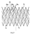
- one of the axes in helix has also been identified at 39. (once the structure is closed on itself) along which develops one of the meandering lines 33.
- helical meanders 33 will be called “first elements structural ". Like the previous meanders, such as 23, they have a succession of vertices linked together, two by two, by sections intermediaries some of which have a shoulder and others not (see section 33a).
- the successive summits are opposite, such as 35a directed towards the end 15a, then 35b directed towards the end 15b.
- the first structural elements 33 are further connected two to two, from one line to an immediately adjacent line, by second discrete structural elements which intersect the first, to constitute the one-piece structure sought.
- these second elements 41 have a shape in "S" (tilted at 90 °) with two rounded tops substantially in the form of a hair (at least in the radially tightened state shown in the structure), like the "second sleepers” 25 in FIG. 6 (these are the same filamentary sections). These sections 41 are connected to inverse vertices (such as 35a, 35b) of two meandering lines 33 adjacent.
- the sections 43 have the shape of an "S" deformed, without vertex, with two successive inverted bends, rounded substantially at 90 °, and marked 43a, 43b, for one of the sections.
- the "second structural elements" 43 and 45 are connected to meander zones, respectively 35, 37, located between two vertices successive inverses of each of these.
- connection is made, to one and the other of its ends, between a vertex and an intermediate shoulder (such as 35c) of each of the two meandering lines 35 concerned.
- Said second structural elements could also be presented as organized along a series of lines that are always parallel between them, but perpendicular to axis 30, with an angular offset circumferential between two adjacent lines (arrangement substantially in staggered).
- Figures 6 and 8 is referenced, respectively, the width of a meandering line 33 and h the height (parallel to the axis 30) of a meandering line 23, this to show that in a case as in the other, second connecting crosspieces (respectively 41 and 27) extend, between two such meandering elements which they connect, over a part of the width (respectively height) occupied by these meanders.
- second connecting crosspieces (respectively 41 and 27) extend, between two such meandering elements which they connect, over a part of the width (respectively height) occupied by these meanders.
Abstract
Description
L'invention concerne un implant médical présentant un axe longitudinal principal et prévu pour être introduit dans un conduit anatomique pour traiter une affection dudit conduit, l'implant étant adapté pour occuper un premier état radialement resserré ou un second état radialement déployé, et présentant une extrémité proximale et une extrémité distale, suivant son axe principal.The invention relates to a medical implant having an axis main longitudinal and intended to be introduced into a duct anatomical to treat a condition of said duct, the implant being adapted to occupy a first radially tightened state or a second state radially extended, and having a proximal end and an end distal, along its main axis.
Un exemple d'un tel implant est représenté sur la figure 1, en tant qu'illustration de l'art antérieur.An example of such an implant is shown in Figure 1, as as illustration of the prior art.
Sur cette figure, on voit une partie d'une structure de paroi tubulaire d'un implant médical 1 intravasculaire, développé à plat.In this figure, we see part of a wall structure tubular of an intravascular medical implant 1, developed flat.
Dans cette illustration, la structure présente la forme qu'elle a
dans l'état radialement déployé de l'implant. L'axe 3 matérialise la direction
longitudinale de l'implant autour de laquelle il se développe suivant
sensiblement un tube couramment cylindrique.In this illustration, the structure has the shape it has
in the radially deployed state of the implant.
On remarque en 5 qu'un tronçon de la structure s'étend à
proximité immédiate et sensiblement parallèlement à un autre tronçon 7 qu'il
vient en quelque sorte doubler. Cette particularité se reproduit en différents
emplacements, tels que ceux repérés A et B sur la figure.Note in 5 that a section of the structure extends to
immediate proximity and substantially parallel to another
Il s'agit là d'un inconvénient dans la mesure où les méandres
sensiblement en zigzags tels que 9a, 9b, 9c paraissent "gauchis". En d'autres
termes, dans son état ouvert, la structure de cet implant (également appelé
stent) ne paraít pas régulière. En outre, l'existence des tronçons 5 et 7 conduit
à une rigidité supérieure du stent en ces endroits à "tronçons doublés", en
comparaison des autres tronçons. L'équilibre général de l'implant peut s'en
ressentir. Il peut également y avoir une influence sur la fiabilité de
l'ouverture, ainsi que sur les caractéristiques mécaniques, voire l'efficacité de
l'implant dans son ensemble, compte tenu de la déformation qu'induit cette
situation sur les cellules 8 de l'implant.This is a drawback insofar as the meanders
substantially in zigzags such as 9a, 9b, 9c appear "warped". In others
terms, in its open state, the structure of this implant (also called
stent) does not appear regular. In addition, the existence of
Pour apporter une solution à ce problème et favoriser la qualité globale de l'implant, l'invention enseigne des modifications qui pouvent être présentées de trois manières différentes, lesquelles ont en commun de résoudre le problème posé.To provide a solution to this problem and promote quality the implant, the invention teaches modifications which can be presented in three different ways, which have in common solve the problem.
Tout d'abord, on peut énoncer que l'invention enseigne de modifier l'implant précité de telle sorte qu'il présente :
- des premiers éléments structurels s'étendant en méandres suivant une série d'hélices parallèles enroulées autour de l'axe longitudinal principal de l'implant, les méandres présentant des sommets ayant des points d'inversion de pente, ces sommets étant dirigés alternativement vers l'extrémité proximale et vers l'extrémité distale,
- des seconds éléments structurels discrets formant des traverses de liaison qui s'étendent individuellement entre deux premiers éléments adjacents qu'elles croisent, ces seconds éléments étant disposés suivant une série de lignes parallèles entre elles et perpendiculaires à l'axe de l'implant,
- lesdits seconds éléments structurels discrets présentant en outre soit uniquement des changements de pente, avec épaulement(s), mais sans inversion de pente, soit des inversions de pente, uniquement, sans épaulement,
- les seconds éléments d'une ligne présentant de préférence un décalage angulaire autour de cet axe vis-à-vis des seconds éléments d'une ligne immédiatement précédente ou suivante.
- first structural elements extending in meanders along a series of parallel helices wound around the main longitudinal axis of the implant, the meanders having vertices having points of inversion of slope, these vertices being directed alternately towards the 'proximal end and towards the distal end,
- second discrete structural elements forming connecting crosspieces which extend individually between two adjacent first elements which they cross, these second elements being arranged in a series of lines parallel to each other and perpendicular to the axis of the implant,
- said second discrete structural elements further having either only slope changes, with shoulder (s), but without slope reversal, or slope reversals, only, without shoulder,
- the second elements of a line preferably having an angular offset around this axis with respect to the second elements of an immediately preceding or following line.
Une autre manière de présenter la solution principale de l'invention consiste à considérer que les ouvertures ou cellules ménagées dans la paroi essentiellement cylindrique de l'implant présentent, tant dans le premier que dans le second état de l'implant, une forme globalement en "Z" qui est délimitée périphériquement, au moins dans ledit état radialement déployé, par huit sommets où il y a une inversion de pente (ou rebroussement, à la manière par exemple d'un sommet de zigzag).Another way to present the main solution of the invention consists in considering that the openings or cells formed in the essentially cylindrical wall of the implant present, both in the first than in the second state of the implant, a generally "Z" which is delimited peripherally, at least in said radially state deployed, by eight vertices where there is a slope inversion (or cusp, like a zigzag top).
Une troisième manière de présenter consiste à considérer que l'implant présente des premiers méandres structurels s'étendant essentiellement perpendiculairement à l'axe de l'implant avec des sommets ayant des inversions de pente dirigées alternativement vers l'extrémité proximale puis vers l'extrémité distale, ces sommets étant reliés entre eux par des tronçons intermédiaires de liaison, pour définir une série d'anneaux, plusieurs tels anneaux étant étagés suivant l'axe de l'implant, un premier et un second étages annulaires adjacents qui se succèdent suivant cet axe étant reliés entre eux par des secondes et troisièmes traverses de liaison, discrètes, de formes différentes, croisant les premiers méandres structurels du premier et du second étages, respectivement, ces croisements étant situés à l'endroit de sommets desdits premiers méandres, pour les secondes traverses, et à l'endroit de tronçons intermédiaires de ces mêmes premiers méandres, pour les troisièmes traverses.A third way of presenting is to consider that the implant has first structural meanders extending essentially perpendicular to the axis of the implant with vertices having slope reversals directed alternately towards the end proximal then towards the distal end, these vertices being interconnected by intermediate link sections, to define a series of rings, several such rings being stepped along the axis of the implant, a first and a second adjacent annular stage which follow one another along this axis being connected to each other by discrete second and third connecting crosspieces, of different shapes, crossing the first structural meanders of the first and second floors, respectively, these crossings being located at the place of summits of said first meanders, for the second sleepers, and at the location of intermediate sections of these same first meanders, for the third sleepers.
En relation avec les première et troisième manières de présenter la solution de l'invention, il est conseillé:
- que les seconds éléments structurels (ou secondes traverses) qui présentent des points d'inversion de pente, mais pas d'épaulement, croisent les premiers éléments (ou méandres) structurels à l'endroit des sommets de ces derniers,
- tandis qu'au contraire, les seconds éléments structurels (ou troisièmes traverses) qui présentent au moins un épaulement, mais pas de zone d'inversion de pente, croiseront avantageusement les premiers éléments, ou méandres, structurels uniquement à l'endroit de certains des tronçons intermédiaires de ces derniers situés entre deux sommets.
- that the second structural elements (or second sleepers) which have points of slope inversion, but not of shoulder, cross the first structural elements (or meanders) at the location of the vertices of the latter,
- while on the contrary, the second structural elements (or third crosspieces) which have at least one shoulder, but no slope inversion zone, will advantageously cross the first structural elements, or meanders, only at the location of some of the intermediate sections of the latter located between two vertices.
Toujours en relation avec les problèmes précités, on notera qu'une autre caractéristique de l'invention conseille que les secondes traverses, c'est-à-dire les seconds éléments structurels discrets sensiblement en "zigzags" (avec sommets, mais sans zone d'épaulement) s'étendent entre les deux premiers éléments, ou premiers méandres, structurels qu'elles relient, sur une partie au moins de la hauteur (ou largeur) occupée par ces derniers, avec pour avantage de contrôler la taille des cellules de l'implant, en particulier dans son état ouvert. Still in relation to the aforementioned problems, it will be noted that a another characteristic of the invention recommends that the second sleepers, that is to say the second discrete structural elements substantially in "zigzags" (with vertices, but without shoulder area) extend between the two first elements, or first meanders, structural that they connect, on at least part of the height (or width) occupied by them, with the advantage of controlling the size of the implant cells, in particular in its open state.
Une description plus détaillée de l'invention va maintenant être fournie en relation avec les dessins annexés dans lesquels :
- la figure 1 montre, en vue développée à plat, une structure d'implant illustrative de l'art antérieur,
- la figure 2 montre un implant (stent) conforme à l'invention, dans son état radialement resserré,
- la figure 3 montre, en vue partielle développée à plat, la forme de la structure de la figure 1, en vue grossie,
- la figure 4 montre une cellule de la structure de la figure 3,
- la figure 5 montre, en vue développée à plat, une partie de l'implant de la figure 2,
- la figure 6 montre la même structure que la figure 3, mais avec renforcement des lignes de méandres perpendiculaires à l'axe longitudinal de l'implant,
- la figure 7 correspond à la figure 5, mais avec les lignes renforcées de la figure 6,
- et les figures 8, 9 et 10 reprennent l'illustration des figures 3 et 6, mais avec un renforcement des lignes de méandres "en hélices".
- FIG. 1 shows, in a flat developed view, an illustrative implant structure of the prior art,
- FIG. 2 shows an implant (stent) according to the invention, in its radially tightened state,
- FIG. 3 shows, in partial view developed flat, the shape of the structure of FIG. 1, in enlarged view,
- FIG. 4 shows a cell of the structure of FIG. 3,
- FIG. 5 shows, in a flat developed view, part of the implant of FIG. 2,
- FIG. 6 shows the same structure as FIG. 3, but with reinforcement of the meander lines perpendicular to the longitudinal axis of the implant,
- FIG. 7 corresponds to FIG. 5, but with the reinforced lines of FIG. 6,
- and FIGS. 8, 9 and 10 repeat the illustration of FIGS. 3 and 6, but with a reinforcement of the meandering lines "in helices".
Sur la figure 2, on voit globalement l'aspect d'un stent 10 conforme
à l'invention.In Figure 2, we generally see the appearance of a
Comme couramment employé, le terme "stent" désigne un implant destiné à être introduit dans un conduit naturel d'un corps, tel en particulier qu'un vaisseau. Il s'agit typiquement d'une structure de soutien de la paroi du conduit (vaisseau iliaque notamment) qui peut être utilisée comme élargisseur, tout particulièrement en cas de sténose.As commonly used, the term "stent" denotes a implant intended to be introduced into a natural conduit of a body, such as particular than a ship. This is typically a support structure of the duct wall (iliac vessel in particular) which can be used as an enlarger, especially in cases of stenosis.
L'implant 10 présente un axe longitudinal 30 autour duquel sa
structure 11 s'étend, en présentant une forme tubulaire, cylindrique, que l'on
distingue habituellement mieux dans son état radialement déployé. The
Sur la figure 2, le stent est dans son état radialement resserré, prêt à être introduit dans le conduit concerné, en particulier par voie endoluminale, par exemple par la technique dite "de SELDINGER".In Figure 2, the stent is in its radially tightened state, ready to be introduced into the concerned conduit, in particular by way endoluminal, for example by the so-called "SELDINGER" technique.
La structure 11 est de préférence métallique. Elle peut être à base
d'acier inoxydable ou en alliage à mémoire de forme thermique (tel que du
"Nitinol"®).The
Sur la figure 3, on retrouve en vue agrandie et dans des
proportions différentes le dessin de la structure 11 dont on a volontairement
écarté les lignes pour le rendre plus lisible.In FIG. 3, we find in enlarged view and in
different proportions the drawing of the
On remarquera que la structure 11 est monobloc et comporte une
succession de cellules, ou "ouvertures" traversantes, 13, dont l'une a été
représentée sur la figure 4.It will be noted that the
En l'espèce, toutes les cellules de la structure sont identiques (sauf à la limite les cellules des deux extrémités, respectivement proximale, 15a, et distale 15b, où tous les angles sont arrondis).In this case, all the cells of the structure are identical (except at the limit, the cells of the two ends, respectively proximal, 15a, and distal 15b, where all the angles are rounded).
Sur les figures 3 et 4, on remarquera la forme globalement en "Z"
ou en "S" de chaque cellule 13, cette forme pouvant être retrouvée sur la
figure 5, où l'on voit toujours un détail agrandi de la structure 11, mais dans
un état radialement déployé par rapport à l'axe longitudinal 30.In Figures 3 and 4, note the overall shape in "Z"
or in "S" of each
Sur les figures 3 et 4, chaque cellule 13 est périmétriquement
délimitée par six sommets 17a, 17b, 17c, 17d, 17e, 17f, c'est-à-dire six zones
d'inversion de pente ou encore "de rebroussement", ces six sommets
devenant huit dans l'état radialement déployé (figure 5), avec les sommets
17g, 17h, créés par les tronçons de raccordement de la cellule aux cellules
adjacentes et dont on voit les amorces sur la figure 4.In FIGS. 3 and 4, each
Cette forme de cellules en "Z" présente un avantage certain par
rapport à la forme des cellules de la figure 1 et qui est moins régulière,
compte tenu de l'existence du tronçon 5. This form of "Z" cells has a definite advantage by
compared to the shape of the cells in FIG. 1 and which is less regular,
taking into account the existence of
Sur la figure 5, on peut constater que ce tronçon a disparu, comme montré aux emplacements C et D, ce qui permet une ouverture radiale plus équilibrée de l'implant, en particulier.In Figure 5, we can see that this section has disappeared, as shown in locations C and D, allowing more radial opening balanced implant, in particular.
Par rapport aux cellules de la figure 1, celles de l'implant de l'invention comprennent au moins un sommet de moins.Compared to the cells of FIG. 1, those of the implant of the invention include at least one less vertex.
Sur la figure 6, on a renforcé le trait des méandres constitués par
les lignes structurelles que l'on voit ici développées à plat et qui s'étendent
donc perpendiculairement à l'axe longitudinal 30, en définissant, le long de
l'axe 30, une série d'étages annulaires (une fois ces lignes refermées chacune
sur elles-mêmes) tels que 19a, 19b, 19c.In FIG. 6, the line of meanders formed by
the structural lines that we see here developed flat and which extend
therefore perpendicular to the
Les méandres de chaque étage (que l'on retrouve à l'identique d'étage en étage, à la seule différence près, aux deux extrémités, que tous les sommets sont plus arrondis) sont constitués d'une succession de sommets tels que 21a, 21b, 21c, réunis successivement deux à deux par des tronçons intermédiaires tels que 23a, 23b.The meanders of each floor (which can be found identically from floor to floor, with the only difference, at both ends, that all vertices are more rounded) consist of a succession of vertices such as 21a, 21b, 21c, joined successively two by two by sections intermediaries such as 23a, 23b.
On appellera ces méandres des "premiers méandres structurels" référencés 23.These meanders will be called "first structural meanders" referenced 23.
Sur les figures 6 et 7, on peut constater que lesdits méandres de
deux étages adjacents, tels que 19a, 19b, sont réunis entre eux par des
secondes et des troisièmes traverses de liaison 25 et 27, respectivement.In FIGS. 6 and 7, it can be seen that said meanders of
two adjacent stages, such as 19a, 19b, are joined together by
seconds and
Tant dans l'état radialement resserré que dans l'état radialement
déployé, les secondes et troisièmes traverses, qui sont courbes, présentent
exclusivement comme zones de courbure, deux sommets inversés 25a, 25b, et
un épaulement 27a, respectivement.Both in the radially tightened state and in the radially tightened state
deployed, the second and third crossbars, which are curved, have
exclusively as zones of curvature, two
Ainsi, les secondes traverses 25 présentent uniquement des
tronçons rectilignes entre leurs deux sommets, 25a, 25b, où la pente de la
traverse s'inverse sensiblement en épingle à cheveux, successivement dans
un sens et dans l'autre. Thus, the
Par contre, chaque troisième traverse 27 présente, sensiblement à
mi-longueur, un épaulement arrondi, avec donc changement de pente, mais
sans inversion.On the other hand, each
Pour obtenir la forme sensiblement en "Z" des cellules 13, les
secondes traverses 25 (qui ont donc une forme sensiblement en "S") sont
raccordées, à chacune de leurs extrémités, à l'endroit de sommets opposés
des méandres constituant les deux étages adjacents considérés, tandis que les
extrémités des troisièmes traverses 27 sont raccordées en des zones
intermédiaires entre deux sommets successifs d'un même étage.To obtain the substantially "Z" shape of
On aura compris que l'on appelle "sommets opposés", deux sommets dirigés, pour l'un, vers l'extrémité proximale et, pour l'autre, vers l'extrémité distale de la structure.We will understand that we call "opposite vertices", two vertices directed, for one, towards the proximal end and, for the other, towards the distal end of the structure.
Dans l'état resserré, aucun sommet n'est d'ailleurs dirigé autrement que vers l'extrémité distale ou proximale de l'implant.In the tightened state, no summit is in fact directed other than towards the distal or proximal end of the implant.
Deux lignes en méandres définissant deux étages adjacents tels que 19a, 19b, sont par ailleurs décalées circonférenciellement l'une par rapport à l'autre, avec un décalage de phase partiel.Two meandering lines defining two adjacent floors such that 19a, 19b, are furthermore circumferentially offset one by compared to the other, with a partial phase shift.
On notera également que les raccordements des secondes
traverses 25 s'effectuent entre sommets "extrêmes" des méandres de deux
étages adjacents, c'est-à-dire avec des sommets qui, dans un sens ou en sens
opposé, sont les plus "hauts" des méandres, à la différence par exemple des
sommets "moins hauts" tels que les sommets arrondis 29a, 29b, de part et
d'autre desquels se raccordent des troisièmes traverses 27, en zone
intermédiaire entre l'un de ces sommets et un sommet "haut" suivant, tel que
31b, ou précédent, tel que 31a.Note also that the
Concernant les troisièmes traverses 27, on notera comme le voit
peut-être plus distinctement aux endroits renforcés en gras, que la forme des
troisièmes traverses 27, en liaison avec le raccordement de leur extrémité
inférieure 27b, favorise bien l'équilibre général de l'implant et autorise
l'obtention des cellules 13 en "Z" précitées, ceci en conjonction avec la forme
et les points d'attache des secondes traverses 25, comme on le peut le voir en
particulier sur la figure 5.Regarding the
Si l'on ne raisonne plus en termes de "cellules", ni en termes
d'étages annulaires sensiblement perpendiculaires à l'axe 30, mais plutôt
avec une approche longitudinale, la vision que l'on a de la structure 11 de
l'implant est encore différente, comme en témoignent les figures 8, 9 et 10 où
l'on a renforcé le trait des méandres qui se développent, en hélices,
parallèlement les uns aux autres autour de l'axe 30.If we no longer reason in terms of "cells", nor in terms
annular stages substantially perpendicular to
Sur ces figures, on a repéré successivement ces lignes de méandres, 33 (figure 8), 35 (figure 9) et 37 (figure 10).In these figures, we have successively identified these lines of meanders, 33 (figure 8), 35 (figure 9) and 37 (figure 10).
Sur la figure 8, on a en outre repéré en 39 l'un des axes en hélice
(une fois la structure refermée sur elle-même) le long duquel se développe
l'une des lignes en méandres 33.In FIG. 8, one of the axes in helix has also been identified at 39.
(once the structure is closed on itself) along which develops
one of the
Ces méandres en hélices 33 seront dénommées "premiers éléments
structurels". Comme les méandres précédents, tels que 23, ils présentent une
succession de sommets reliés entre eux, deux à deux, par des tronçons
intermédiaires dont certains présentent un épaulement et d'autres non (voir
tronçon 33a).These
Bien entendu, pour former les méandres, les sommets successifs
sont opposés, tels que 35a dirigé vers l'extrémité 15a, puis 35b dirigé vers
l'extrémité 15b.Of course, to form the meanders, the successive summits
are opposite, such as 35a directed towards the
On notera une fois encore le décalage angulaire partiel des méandres sur la circonférence de la structure.Once again, note the partial angular shift of meanders on the circumference of the structure.
Les premiers éléments structurels 33 sont en outre reliés deux à
deux, d'une ligne à une ligne immédiatement adjacente, par des seconds
éléments structurels discrets qui intersectent les premiers, pour constituer la
structure monobloc recherchée.The first
Sur les figures 8, 9 et 10, on a successivement repéré ces seconds
éléments 41, 43 et 45. In Figures 8, 9 and 10, we have successively identified these
Sur la figure 8, ces seconds éléments 41 présentent une forme en
"S" (basculée à 90°) à deux sommets arrondis sensiblement en épingle à
cheveux (du moins dans l'état radialement resserré représenté de la
structure), à l'image des "secondes traverses" 25 de la figure 6 (ce sont
d'ailleurs les mêmes tronçons filamentaires). Ces tronçons 41 se raccordent à
des sommets inverses (tels que 35a, 35b) de deux lignes de méandres 33
adjacentes.In FIG. 8, these
Sur la figure 9, les tronçons 43 présentent une forme de "S"
déformée, sans sommet, avec deux coudes successifs inversés, arrondis
sensiblement à 90°, et repérés 43a, 43b, pour l'un des tronçons.In FIG. 9, the
Sur la figure 10, on retrouve encore cet aspect sensiblement de "S" déformé avec deux coudes successifs arrondis sensiblement à 90°, repérés 45a, 45b, pour ces deux éléments structurels discrets 45 (la forme du "S" est basculée de 90° verticalement, comme sur la figure 8).In FIG. 10, we still find this aspect substantially of "S" deformed with two successive bends rounded substantially 90 °, marked 45a, 45b, for these two discrete structural elements 45 (the shape of the "S" is tilted 90 ° vertically, as in figure 8).
Les "seconds éléments structurels" 43 et 45 se raccordent à des zones de méandres, respectivement 35, 37, situées entre deux sommets inverses successifs de chacun de ces derniers.The "second structural elements" 43 and 45 are connected to meander zones, respectively 35, 37, located between two vertices successive inverses of each of these.
Pour chaque élément 43, le raccordement s'effectue, à l'une et
l'autre de ses extrémités, entre un sommet et un épaulement intermédiaire
(tel que 35c) de chacune des deux lignes en méandres 35 concernées.For each
Pour chaque élément 45, le raccordement des extrémités s'effectue
à l'endroit d'épaulements 37a présents sur les deux lignes successives en
méandres 37 concernées.For each
Une constante à remarquer sur les figures 8 à 10 ; on ne trouve pas d'élément structurel discret entre les méandres continus en hélices (33, 35, 37) qui présente à la fois des zones d'épaulement (avec donc un ressaut arrondi; tels que 43a, 43b ; 45a, 45b) et des sommets (avec donc une inversion de pente ; tronçon 41), comme on en trouve dans l'art antérieur de la figure 1. A constant to be noted in Figures 8 to 10; we do not find of discrete structural element between the continuous meanders in helices (33, 35, 37) which has both shoulder zones (thus with a projection round; such as 43a, 43b; 45a, 45b) and vertices (with therefore a slope inversion; section 41), as found in the prior art of Figure 1.
On pourra également remarquer que les seconds éléments discrets
précités 41, 43, 45, s'étendent suivant une série de lignes parallèles entre elles
qui forment également des hélices s'enroulant autour de l'axe 30.We can also notice that the second discrete elements
cited above 41, 43, 45, extend in a series of lines parallel to each other
which also form helices winding around the
Lesdits seconds éléments structurels pourraient également être
présentés comme organisés suivant une série de lignes toujours parallèles
entre elles, mais perpendiculaires à l'axe 30, avec un décalage angulaire
circonférenciel entre deux lignes adjacentes (disposition sensiblement en
quinconce).Said second structural elements could also be
presented as organized along a series of lines that are always parallel
between them, but perpendicular to
Sur les figures 6 et 8, on a référencé, respectivement, l la largeur
d'une ligne de méandres 33 et h la hauteur (parallèlement à l'axe 30) d'une
ligne de méandres 23, ceci pour montrer que, dans un cas comme dans
l'autre, des secondes traverses de liaison (respectivement 41 et 27) s'étendent,
entre deux tels éléments en méandres qu'elles relient, sur une partie de la
largeur (respectivement hauteur) occupée par ces méandres. Une
conséquence de cela est que l'on obtient des cellules de taille adaptée, avec la
forme souhaitée, en évitant notamment le gauchissement de l'illustration de
la figure 1.Figures 6 and 8, is referenced, respectively, the width of a
Claims (9)
Applications Claiming Priority (2)
| Application Number | Priority Date | Filing Date | Title |
|---|---|---|---|
| FR9912630 | 1999-10-11 | ||
| FR9912630A FR2799363B1 (en) | 1999-10-11 | 1999-10-11 | MEDICAL IMPLANT IN MEANDRES IN ZIGZAG |
Publications (2)
| Publication Number | Publication Date |
|---|---|
| EP1092401A1 true EP1092401A1 (en) | 2001-04-18 |
| EP1092401B1 EP1092401B1 (en) | 2007-12-19 |
Family
ID=9550766
Family Applications (1)
| Application Number | Title | Priority Date | Filing Date |
|---|---|---|---|
| EP00402764A Expired - Lifetime EP1092401B1 (en) | 1999-10-11 | 2000-10-06 | Helical stent |
Country Status (7)
| Country | Link |
|---|---|
| US (1) | US6620201B1 (en) |
| EP (1) | EP1092401B1 (en) |
| JP (1) | JP2001137353A (en) |
| CA (1) | CA2321351A1 (en) |
| DE (1) | DE60037489T2 (en) |
| ES (1) | ES2296600T3 (en) |
| FR (1) | FR2799363B1 (en) |
Cited By (12)
| Publication number | Priority date | Publication date | Assignee | Title |
|---|---|---|---|---|
| EP2098195A1 (en) * | 2006-12-28 | 2009-09-09 | Terumo Kabushiki Kaisha | Self-expansion stent |
| US7704267B2 (en) | 2004-08-04 | 2010-04-27 | C. R. Bard, Inc. | Non-entangling vena cava filter |
| US7794473B2 (en) | 2004-11-12 | 2010-09-14 | C.R. Bard, Inc. | Filter delivery system |
| US8267954B2 (en) | 2005-02-04 | 2012-09-18 | C. R. Bard, Inc. | Vascular filter with sensing capability |
| US8430903B2 (en) | 2005-08-09 | 2013-04-30 | C. R. Bard, Inc. | Embolus blood clot filter and delivery system |
| US8574261B2 (en) | 2005-05-12 | 2013-11-05 | C. R. Bard, Inc. | Removable embolus blood clot filter |
| US8613754B2 (en) | 2005-05-12 | 2013-12-24 | C. R. Bard, Inc. | Tubular filter |
| US8690906B2 (en) | 1998-09-25 | 2014-04-08 | C.R. Bard, Inc. | Removeable embolus blood clot filter and filter delivery unit |
| US9131999B2 (en) | 2005-11-18 | 2015-09-15 | C.R. Bard Inc. | Vena cava filter with filament |
| US9204956B2 (en) | 2002-02-20 | 2015-12-08 | C. R. Bard, Inc. | IVC filter with translating hooks |
| US9326842B2 (en) | 2006-06-05 | 2016-05-03 | C. R . Bard, Inc. | Embolus blood clot filter utilizable with a single delivery system or a single retrieval system in one of a femoral or jugular access |
| US10188496B2 (en) | 2006-05-02 | 2019-01-29 | C. R. Bard, Inc. | Vena cava filter formed from a sheet |
Families Citing this family (18)
| Publication number | Priority date | Publication date | Assignee | Title |
|---|---|---|---|---|
| US7204848B1 (en) | 1995-03-01 | 2007-04-17 | Boston Scientific Scimed, Inc. | Longitudinally flexible expandable stent |
| EP0884029B1 (en) * | 1997-06-13 | 2004-12-22 | Gary J. Becker | Expandable intraluminal endoprosthesis |
| WO1999044535A1 (en) * | 1998-03-05 | 1999-09-10 | Boston Scientific Limited | Intraluminal stent |
| US7637942B2 (en) | 2002-11-05 | 2009-12-29 | Merit Medical Systems, Inc. | Coated stent with geometry determinated functionality and method of making the same |
| US7959671B2 (en) | 2002-11-05 | 2011-06-14 | Merit Medical Systems, Inc. | Differential covering and coating methods |
| US7875068B2 (en) | 2002-11-05 | 2011-01-25 | Merit Medical Systems, Inc. | Removable biliary stent |
| US7887579B2 (en) | 2004-09-29 | 2011-02-15 | Merit Medical Systems, Inc. | Active stent |
| JP4928891B2 (en) * | 2006-09-29 | 2012-05-09 | テルモ株式会社 | Self-expanding in-vivo stent |
| US7651524B2 (en) | 2005-03-30 | 2010-01-26 | Terumo Kabushiki Kaisha | Flexible stent |
| JP4928813B2 (en) * | 2005-03-30 | 2012-05-09 | テルモ株式会社 | In-vivo stent |
| ATE465699T1 (en) * | 2005-03-30 | 2010-05-15 | Terumo Corp | STENT |
| US7731654B2 (en) | 2005-05-13 | 2010-06-08 | Merit Medical Systems, Inc. | Delivery device with viewing window and associated method |
| PT1752113E (en) | 2005-08-10 | 2009-03-18 | Axetis Ag | Tubular stent with laterally overlapping arcs |
| US20070173925A1 (en) * | 2006-01-25 | 2007-07-26 | Cornova, Inc. | Flexible expandable stent |
| US20080215132A1 (en) * | 2006-08-28 | 2008-09-04 | Cornova, Inc. | Implantable devices having textured surfaces and methods of forming the same |
| US9265636B2 (en) * | 2007-05-25 | 2016-02-23 | C. R. Bard, Inc. | Twisted stent |
| JP5770507B2 (en) * | 2011-03-28 | 2015-08-26 | テルモ株式会社 | Self-expanding stent and stent delivery system |
| US9498360B2 (en) * | 2013-03-15 | 2016-11-22 | Stryker Corporation | Stent and method of use |
Citations (4)
| Publication number | Priority date | Publication date | Assignee | Title |
|---|---|---|---|---|
| WO1998040035A1 (en) * | 1997-03-13 | 1998-09-17 | United States Surgical Corporation | Flexible tissue supporting device |
| WO1998042277A1 (en) * | 1997-03-25 | 1998-10-01 | Jang G David | Intravascular stent |
| EP0884029A1 (en) * | 1997-06-13 | 1998-12-16 | Gary J. Becker | Expandable intraluminal endoprosthesis |
| FR2774278A1 (en) * | 1998-02-02 | 1999-08-06 | Braun Celsa Sa | Anatomical cavity endoprosthesis with deployable one-piece tubular structure |
Family Cites Families (11)
| Publication number | Priority date | Publication date | Assignee | Title |
|---|---|---|---|---|
| US5922021A (en) * | 1996-04-26 | 1999-07-13 | Jang; G. David | Intravascular stent |
| US5776183A (en) * | 1996-08-23 | 1998-07-07 | Kanesaka; Nozomu | Expandable stent |
| US5807404A (en) * | 1996-09-19 | 1998-09-15 | Medinol Ltd. | Stent with variable features to optimize support and method of making such stent |
| US5810872A (en) * | 1997-03-14 | 1998-09-22 | Kanesaka; Nozomu | Flexible stent |
| US6033433A (en) * | 1997-04-25 | 2000-03-07 | Scimed Life Systems, Inc. | Stent configurations including spirals |
| US5913895A (en) * | 1997-06-02 | 1999-06-22 | Isostent, Inc. | Intravascular stent with enhanced rigidity strut members |
| US6129754A (en) * | 1997-12-11 | 2000-10-10 | Uni-Cath Inc. | Stent for vessel with branch |
| US5964798A (en) * | 1997-12-16 | 1999-10-12 | Cardiovasc, Inc. | Stent having high radial strength |
| US6066169A (en) * | 1998-06-02 | 2000-05-23 | Ave Connaught | Expandable stent having articulated connecting rods |
| US5911754A (en) * | 1998-07-24 | 1999-06-15 | Uni-Cath Inc. | Flexible stent with effective strut and connector patterns |
| US6042597A (en) * | 1998-10-23 | 2000-03-28 | Scimed Life Systems, Inc. | Helical stent design |
-
1999
- 1999-10-11 FR FR9912630A patent/FR2799363B1/en not_active Expired - Fee Related
-
2000
- 2000-10-06 CA CA002321351A patent/CA2321351A1/en not_active Abandoned
- 2000-10-06 DE DE60037489T patent/DE60037489T2/en not_active Expired - Lifetime
- 2000-10-06 EP EP00402764A patent/EP1092401B1/en not_active Expired - Lifetime
- 2000-10-06 ES ES00402764T patent/ES2296600T3/en not_active Expired - Lifetime
- 2000-10-06 US US09/680,533 patent/US6620201B1/en not_active Expired - Fee Related
- 2000-10-11 JP JP2000311030A patent/JP2001137353A/en active Pending
Patent Citations (4)
| Publication number | Priority date | Publication date | Assignee | Title |
|---|---|---|---|---|
| WO1998040035A1 (en) * | 1997-03-13 | 1998-09-17 | United States Surgical Corporation | Flexible tissue supporting device |
| WO1998042277A1 (en) * | 1997-03-25 | 1998-10-01 | Jang G David | Intravascular stent |
| EP0884029A1 (en) * | 1997-06-13 | 1998-12-16 | Gary J. Becker | Expandable intraluminal endoprosthesis |
| FR2774278A1 (en) * | 1998-02-02 | 1999-08-06 | Braun Celsa Sa | Anatomical cavity endoprosthesis with deployable one-piece tubular structure |
Cited By (32)
| Publication number | Priority date | Publication date | Assignee | Title |
|---|---|---|---|---|
| US8690906B2 (en) | 1998-09-25 | 2014-04-08 | C.R. Bard, Inc. | Removeable embolus blood clot filter and filter delivery unit |
| US9615909B2 (en) | 1998-09-25 | 2017-04-11 | C.R. Bard, Inc. | Removable embolus blood clot filter and filter delivery unit |
| US9351821B2 (en) | 1998-09-25 | 2016-05-31 | C. R. Bard, Inc. | Removable embolus blood clot filter and filter delivery unit |
| US9204956B2 (en) | 2002-02-20 | 2015-12-08 | C. R. Bard, Inc. | IVC filter with translating hooks |
| US8628556B2 (en) | 2004-08-04 | 2014-01-14 | C. R. Bard, Inc. | Non-entangling vena cava filter |
| US7704267B2 (en) | 2004-08-04 | 2010-04-27 | C. R. Bard, Inc. | Non-entangling vena cava filter |
| US11103339B2 (en) | 2004-08-04 | 2021-08-31 | C. R. Bard, Inc. | Non-entangling vena cava filter |
| US8372109B2 (en) | 2004-08-04 | 2013-02-12 | C. R. Bard, Inc. | Non-entangling vena cava filter |
| US9144484B2 (en) | 2004-08-04 | 2015-09-29 | C. R. Bard, Inc. | Non-entangling vena cava filter |
| US10512531B2 (en) | 2004-11-12 | 2019-12-24 | C. R. Bard, Inc. | Filter delivery system |
| US8992562B2 (en) | 2004-11-12 | 2015-03-31 | C.R. Bard, Inc. | Filter delivery system |
| US7794473B2 (en) | 2004-11-12 | 2010-09-14 | C.R. Bard, Inc. | Filter delivery system |
| US8267954B2 (en) | 2005-02-04 | 2012-09-18 | C. R. Bard, Inc. | Vascular filter with sensing capability |
| US10729527B2 (en) | 2005-05-12 | 2020-08-04 | C.R. Bard, Inc. | Removable embolus blood clot filter |
| US8574261B2 (en) | 2005-05-12 | 2013-11-05 | C. R. Bard, Inc. | Removable embolus blood clot filter |
| US9017367B2 (en) | 2005-05-12 | 2015-04-28 | C. R. Bard, Inc. | Tubular filter |
| US11730583B2 (en) | 2005-05-12 | 2023-08-22 | C.R. Band. Inc. | Tubular filter |
| US8613754B2 (en) | 2005-05-12 | 2013-12-24 | C. R. Bard, Inc. | Tubular filter |
| US10813738B2 (en) | 2005-05-12 | 2020-10-27 | C.R. Bard, Inc. | Tubular filter |
| US9498318B2 (en) | 2005-05-12 | 2016-11-22 | C.R. Bard, Inc. | Removable embolus blood clot filter |
| US10492898B2 (en) | 2005-08-09 | 2019-12-03 | C.R. Bard, Inc. | Embolus blood clot filter and delivery system |
| US8430903B2 (en) | 2005-08-09 | 2013-04-30 | C. R. Bard, Inc. | Embolus blood clot filter and delivery system |
| US9387063B2 (en) | 2005-08-09 | 2016-07-12 | C. R. Bard, Inc. | Embolus blood clot filter and delivery system |
| US11517415B2 (en) | 2005-08-09 | 2022-12-06 | C.R. Bard, Inc. | Embolus blood clot filter and delivery system |
| US9131999B2 (en) | 2005-11-18 | 2015-09-15 | C.R. Bard Inc. | Vena cava filter with filament |
| US10842608B2 (en) | 2005-11-18 | 2020-11-24 | C.R. Bard, Inc. | Vena cava filter with filament |
| US10188496B2 (en) | 2006-05-02 | 2019-01-29 | C. R. Bard, Inc. | Vena cava filter formed from a sheet |
| US10980626B2 (en) | 2006-05-02 | 2021-04-20 | C. R. Bard, Inc. | Vena cava filter formed from a sheet |
| US11141257B2 (en) | 2006-06-05 | 2021-10-12 | C. R. Bard, Inc. | Embolus blood clot filter utilizable with a single delivery system or a single retrieval system in one of a femoral or jugular access |
| US9326842B2 (en) | 2006-06-05 | 2016-05-03 | C. R . Bard, Inc. | Embolus blood clot filter utilizable with a single delivery system or a single retrieval system in one of a femoral or jugular access |
| EP2098195A1 (en) * | 2006-12-28 | 2009-09-09 | Terumo Kabushiki Kaisha | Self-expansion stent |
| EP2098195A4 (en) * | 2006-12-28 | 2012-12-05 | Terumo Corp | Self-expansion stent |
Also Published As
| Publication number | Publication date |
|---|---|
| FR2799363B1 (en) | 2001-11-30 |
| EP1092401B1 (en) | 2007-12-19 |
| US6620201B1 (en) | 2003-09-16 |
| DE60037489T2 (en) | 2008-12-04 |
| CA2321351A1 (en) | 2001-04-11 |
| DE60037489D1 (en) | 2008-01-31 |
| ES2296600T3 (en) | 2008-05-01 |
| FR2799363A1 (en) | 2001-04-13 |
| JP2001137353A (en) | 2001-05-22 |
Similar Documents
| Publication | Publication Date | Title |
|---|---|---|
| EP1092401B1 (en) | Helical stent | |
| EP1052950A1 (en) | Prosthesis with undulating longitudinal braces | |
| US7794491B2 (en) | Apparatus for a stent having an expandable web structure and delivery system | |
| CA2309079C (en) | Stent | |
| AU773171B2 (en) | Stent with optimal strength and radiopacity characteristics | |
| FR2737404A1 (en) | PROSTHESIS IMPLANTABLE IN A HUMAN OR ANIMAL DUCT, SUCH AS A WALL ENLARGEMENT, OR A PROSTHESIS FOR ANEVRISM | |
| EP1374802B2 (en) | Stent with diagonal flexible connecting links | |
| JP2001517536A (en) | Flexible metal wire stent | |
| WO2000025702A1 (en) | Prosthesis for corporeal duct, in particular vascular stent | |
| EP0876806A1 (en) | Vascular and coronary stents | |
| CA2666857A1 (en) | Stent with flexible hinges | |
| JP2008514276A5 (en) | ||
| WO1997046174A1 (en) | Vascular bifurcation endoprosthesis | |
| FR2683449A1 (en) | ENDOPROTHESIS FOR TRANSLUMINAL IMPLANTATION. | |
| FR2781143A1 (en) | Expandable stent for supporting blood vessel has tubular stages defined by regular pattern having consecutive loops closed on themselves, with succession of hairpin-shaped apices | |
| FR2774279A1 (en) | Anatomical cavity endoprosthesis | |
| FR2791551A1 (en) | Expandable stent for supporting blood vessel has tubular stages defined by regular pattern having consecutive loops closed on themselves, with succession of hairpin-shaped apices | |
| FR2768919A1 (en) | EXPANDABLE SUPPORT FOR ANATOMICAL DUCT | |
| FR2784574A1 (en) | One-piece tubular endoprosthesis for anatomical duct | |
| FR2773987A1 (en) | One-piece tubular endoprosthesis for anatomical cavity or duct e.g. blood vessel | |
| JP2005066203A (en) | Flexible stent which expands uniformly | |
| FR2998165A1 (en) | VEIN FILTER | |
| FR2813785A1 (en) | Net to be used as stent, comprising specific arrangement between rows of zigzagging filaments and links positioned between them | |
| FR2784573A1 (en) | One-piece tubular endoprosthesis for anatomical duct | |
| FR2774278A1 (en) | Anatomical cavity endoprosthesis with deployable one-piece tubular structure |
Legal Events
| Date | Code | Title | Description |
|---|---|---|---|
| PUAI | Public reference made under article 153(3) epc to a published international application that has entered the european phase |
Free format text: ORIGINAL CODE: 0009012 |
|
| AK | Designated contracting states |
Kind code of ref document: A1 Designated state(s): DE ES FR GB IT |
|
| AX | Request for extension of the european patent |
Free format text: AL;LT;LV;MK;RO;SI |
|
| 17P | Request for examination filed |
Effective date: 20010921 |
|
| AKX | Designation fees paid |
Free format text: DE ES FR GB IT |
|
| 17Q | First examination report despatched |
Effective date: 20040203 |
|
| GRAP | Despatch of communication of intention to grant a patent |
Free format text: ORIGINAL CODE: EPIDOSNIGR1 |
|
| GRAS | Grant fee paid |
Free format text: ORIGINAL CODE: EPIDOSNIGR3 |
|
| GRAA | (expected) grant |
Free format text: ORIGINAL CODE: 0009210 |
|
| AK | Designated contracting states |
Kind code of ref document: B1 Designated state(s): DE ES FR GB IT |
|
| REG | Reference to a national code |
Ref country code: GB Ref legal event code: FG4D Free format text: NOT ENGLISH |
|
| REF | Corresponds to: |
Ref document number: 60037489 Country of ref document: DE Date of ref document: 20080131 Kind code of ref document: P |
|
| REG | Reference to a national code |
Ref country code: ES Ref legal event code: FG2A Ref document number: 2296600 Country of ref document: ES Kind code of ref document: T3 |
|
| GBV | Gb: ep patent (uk) treated as always having been void in accordance with gb section 77(7)/1977 [no translation filed] | ||
| PLBE | No opposition filed within time limit |
Free format text: ORIGINAL CODE: 0009261 |
|
| STAA | Information on the status of an ep patent application or granted ep patent |
Free format text: STATUS: NO OPPOSITION FILED WITHIN TIME LIMIT |
|
| 26N | No opposition filed |
Effective date: 20080922 |
|
| PG25 | Lapsed in a contracting state [announced via postgrant information from national office to epo] |
Ref country code: GB Free format text: LAPSE BECAUSE OF FAILURE TO SUBMIT A TRANSLATION OF THE DESCRIPTION OR TO PAY THE FEE WITHIN THE PRESCRIBED TIME-LIMIT Effective date: 20071219 |
|
| REG | Reference to a national code |
Ref country code: DE Ref legal event code: R082 Ref document number: 60037489 Country of ref document: DE Representative=s name: PETER MAHLER, DE |
|
| REG | Reference to a national code |
Ref country code: DE Ref legal event code: R082 Ref document number: 60037489 Country of ref document: DE Representative=s name: MAHLER, PETER, DIPL.-PHYS., DE Effective date: 20110812 Ref country code: DE Ref legal event code: R081 Ref document number: 60037489 Country of ref document: DE Owner name: SCION MEDICAL LTD., CN Free format text: FORMER OWNER: B. BRAUN MEDICAL S.A., BOULOGNE BILLANCOURT, FR Effective date: 20110812 |
|
| PGFP | Annual fee paid to national office [announced via postgrant information from national office to epo] |
Ref country code: IT Payment date: 20120128 Year of fee payment: 12 |
|
| PGFP | Annual fee paid to national office [announced via postgrant information from national office to epo] |
Ref country code: ES Payment date: 20120127 Year of fee payment: 12 |
|
| PG25 | Lapsed in a contracting state [announced via postgrant information from national office to epo] |
Ref country code: IT Free format text: LAPSE BECAUSE OF NON-PAYMENT OF DUE FEES Effective date: 20121006 |
|
| REG | Reference to a national code |
Ref country code: ES Ref legal event code: FD2A Effective date: 20140514 |
|
| PG25 | Lapsed in a contracting state [announced via postgrant information from national office to epo] |
Ref country code: ES Free format text: LAPSE BECAUSE OF NON-PAYMENT OF DUE FEES Effective date: 20121007 |
|
| REG | Reference to a national code |
Ref country code: DE Ref legal event code: R082 Ref document number: 60037489 Country of ref document: DE Representative=s name: MAHLER, PETER, DIPL.-PHYS., DE |
|
| REG | Reference to a national code |
Ref country code: DE Ref legal event code: R081 Ref document number: 60037489 Country of ref document: DE Owner name: SCION MEDICAL LTD., CN Free format text: FORMER OWNER: B. BRAUN MEDICAL SAS, BOULOGNE BILLANCOURT, FR Effective date: 20140624 Ref country code: DE Ref legal event code: R082 Ref document number: 60037489 Country of ref document: DE Representative=s name: MAHLER, PETER, DIPL.-PHYS., DE Effective date: 20140624 |
|
| PGFP | Annual fee paid to national office [announced via postgrant information from national office to epo] |
Ref country code: FR Payment date: 20140416 Year of fee payment: 14 Ref country code: DE Payment date: 20140416 Year of fee payment: 14 |
|
| REG | Reference to a national code |
Ref country code: DE Ref legal event code: R119 Ref document number: 60037489 Country of ref document: DE |
|
| PG25 | Lapsed in a contracting state [announced via postgrant information from national office to epo] |
Ref country code: DE Free format text: LAPSE BECAUSE OF NON-PAYMENT OF DUE FEES Effective date: 20150501 |
|
| REG | Reference to a national code |
Ref country code: FR Ref legal event code: ST Effective date: 20150630 |
|
| PG25 | Lapsed in a contracting state [announced via postgrant information from national office to epo] |
Ref country code: FR Free format text: LAPSE BECAUSE OF NON-PAYMENT OF DUE FEES Effective date: 20141031 |