EP1094327A1 - Battery voltage measuring device - Google Patents
Battery voltage measuring device Download PDFInfo
- Publication number
- EP1094327A1 EP1094327A1 EP00121866A EP00121866A EP1094327A1 EP 1094327 A1 EP1094327 A1 EP 1094327A1 EP 00121866 A EP00121866 A EP 00121866A EP 00121866 A EP00121866 A EP 00121866A EP 1094327 A1 EP1094327 A1 EP 1094327A1
- Authority
- EP
- European Patent Office
- Prior art keywords
- voltage
- battery
- measuring line
- breakage
- voltage measuring
- Prior art date
- Legal status (The legal status is an assumption and is not a legal conclusion. Google has not performed a legal analysis and makes no representation as to the accuracy of the status listed.)
- Granted
Links
Images

Classifications
-
- B—PERFORMING OPERATIONS; TRANSPORTING
- B60—VEHICLES IN GENERAL
- B60K—ARRANGEMENT OR MOUNTING OF PROPULSION UNITS OR OF TRANSMISSIONS IN VEHICLES; ARRANGEMENT OR MOUNTING OF PLURAL DIVERSE PRIME-MOVERS IN VEHICLES; AUXILIARY DRIVES FOR VEHICLES; INSTRUMENTATION OR DASHBOARDS FOR VEHICLES; ARRANGEMENTS IN CONNECTION WITH COOLING, AIR INTAKE, GAS EXHAUST OR FUEL SUPPLY OF PROPULSION UNITS IN VEHICLES
- B60K6/00—Arrangement or mounting of plural diverse prime-movers for mutual or common propulsion, e.g. hybrid propulsion systems comprising electric motors and internal combustion engines ; Control systems therefor, i.e. systems controlling two or more prime movers, or controlling one of these prime movers and any of the transmission, drive or drive units Informative references: mechanical gearings with secondary electric drive F16H3/72; arrangements for handling mechanical energy structurally associated with the dynamo-electric machine H02K7/00; machines comprising structurally interrelated motor and generator parts H02K51/00; dynamo-electric machines not otherwise provided for in H02K see H02K99/00
- B60K6/20—Arrangement or mounting of plural diverse prime-movers for mutual or common propulsion, e.g. hybrid propulsion systems comprising electric motors and internal combustion engines ; Control systems therefor, i.e. systems controlling two or more prime movers, or controlling one of these prime movers and any of the transmission, drive or drive units Informative references: mechanical gearings with secondary electric drive F16H3/72; arrangements for handling mechanical energy structurally associated with the dynamo-electric machine H02K7/00; machines comprising structurally interrelated motor and generator parts H02K51/00; dynamo-electric machines not otherwise provided for in H02K see H02K99/00 the prime-movers consisting of electric motors and internal combustion engines, e.g. HEVs
- B60K6/22—Arrangement or mounting of plural diverse prime-movers for mutual or common propulsion, e.g. hybrid propulsion systems comprising electric motors and internal combustion engines ; Control systems therefor, i.e. systems controlling two or more prime movers, or controlling one of these prime movers and any of the transmission, drive or drive units Informative references: mechanical gearings with secondary electric drive F16H3/72; arrangements for handling mechanical energy structurally associated with the dynamo-electric machine H02K7/00; machines comprising structurally interrelated motor and generator parts H02K51/00; dynamo-electric machines not otherwise provided for in H02K see H02K99/00 the prime-movers consisting of electric motors and internal combustion engines, e.g. HEVs characterised by apparatus, components or means specially adapted for HEVs
- B60K6/28—Arrangement or mounting of plural diverse prime-movers for mutual or common propulsion, e.g. hybrid propulsion systems comprising electric motors and internal combustion engines ; Control systems therefor, i.e. systems controlling two or more prime movers, or controlling one of these prime movers and any of the transmission, drive or drive units Informative references: mechanical gearings with secondary electric drive F16H3/72; arrangements for handling mechanical energy structurally associated with the dynamo-electric machine H02K7/00; machines comprising structurally interrelated motor and generator parts H02K51/00; dynamo-electric machines not otherwise provided for in H02K see H02K99/00 the prime-movers consisting of electric motors and internal combustion engines, e.g. HEVs characterised by apparatus, components or means specially adapted for HEVs characterised by the electric energy storing means, e.g. batteries or capacitors
-
- G—PHYSICS
- G01—MEASURING; TESTING
- G01R—MEASURING ELECTRIC VARIABLES; MEASURING MAGNETIC VARIABLES
- G01R19/00—Arrangements for measuring currents or voltages or for indicating presence or sign thereof
-
- B—PERFORMING OPERATIONS; TRANSPORTING
- B60—VEHICLES IN GENERAL
- B60K—ARRANGEMENT OR MOUNTING OF PROPULSION UNITS OR OF TRANSMISSIONS IN VEHICLES; ARRANGEMENT OR MOUNTING OF PLURAL DIVERSE PRIME-MOVERS IN VEHICLES; AUXILIARY DRIVES FOR VEHICLES; INSTRUMENTATION OR DASHBOARDS FOR VEHICLES; ARRANGEMENTS IN CONNECTION WITH COOLING, AIR INTAKE, GAS EXHAUST OR FUEL SUPPLY OF PROPULSION UNITS IN VEHICLES
- B60K6/00—Arrangement or mounting of plural diverse prime-movers for mutual or common propulsion, e.g. hybrid propulsion systems comprising electric motors and internal combustion engines ; Control systems therefor, i.e. systems controlling two or more prime movers, or controlling one of these prime movers and any of the transmission, drive or drive units Informative references: mechanical gearings with secondary electric drive F16H3/72; arrangements for handling mechanical energy structurally associated with the dynamo-electric machine H02K7/00; machines comprising structurally interrelated motor and generator parts H02K51/00; dynamo-electric machines not otherwise provided for in H02K see H02K99/00
- B60K6/20—Arrangement or mounting of plural diverse prime-movers for mutual or common propulsion, e.g. hybrid propulsion systems comprising electric motors and internal combustion engines ; Control systems therefor, i.e. systems controlling two or more prime movers, or controlling one of these prime movers and any of the transmission, drive or drive units Informative references: mechanical gearings with secondary electric drive F16H3/72; arrangements for handling mechanical energy structurally associated with the dynamo-electric machine H02K7/00; machines comprising structurally interrelated motor and generator parts H02K51/00; dynamo-electric machines not otherwise provided for in H02K see H02K99/00 the prime-movers consisting of electric motors and internal combustion engines, e.g. HEVs
- B60K6/42—Arrangement or mounting of plural diverse prime-movers for mutual or common propulsion, e.g. hybrid propulsion systems comprising electric motors and internal combustion engines ; Control systems therefor, i.e. systems controlling two or more prime movers, or controlling one of these prime movers and any of the transmission, drive or drive units Informative references: mechanical gearings with secondary electric drive F16H3/72; arrangements for handling mechanical energy structurally associated with the dynamo-electric machine H02K7/00; machines comprising structurally interrelated motor and generator parts H02K51/00; dynamo-electric machines not otherwise provided for in H02K see H02K99/00 the prime-movers consisting of electric motors and internal combustion engines, e.g. HEVs characterised by the architecture of the hybrid electric vehicle
- B60K6/48—Parallel type
-
- B—PERFORMING OPERATIONS; TRANSPORTING
- B60—VEHICLES IN GENERAL
- B60L—PROPULSION OF ELECTRICALLY-PROPELLED VEHICLES; SUPPLYING ELECTRIC POWER FOR AUXILIARY EQUIPMENT OF ELECTRICALLY-PROPELLED VEHICLES; ELECTRODYNAMIC BRAKE SYSTEMS FOR VEHICLES IN GENERAL; MAGNETIC SUSPENSION OR LEVITATION FOR VEHICLES; MONITORING OPERATING VARIABLES OF ELECTRICALLY-PROPELLED VEHICLES; ELECTRIC SAFETY DEVICES FOR ELECTRICALLY-PROPELLED VEHICLES
- B60L58/00—Methods or circuit arrangements for monitoring or controlling batteries or fuel cells, specially adapted for electric vehicles
- B60L58/10—Methods or circuit arrangements for monitoring or controlling batteries or fuel cells, specially adapted for electric vehicles for monitoring or controlling batteries
- B60L58/18—Methods or circuit arrangements for monitoring or controlling batteries or fuel cells, specially adapted for electric vehicles for monitoring or controlling batteries of two or more battery modules
-
- G—PHYSICS
- G01—MEASURING; TESTING
- G01R—MEASURING ELECTRIC VARIABLES; MEASURING MAGNETIC VARIABLES
- G01R31/00—Arrangements for testing electric properties; Arrangements for locating electric faults; Arrangements for electrical testing characterised by what is being tested not provided for elsewhere
- G01R31/36—Arrangements for testing, measuring or monitoring the electrical condition of accumulators or electric batteries, e.g. capacity or state of charge [SoC]
- G01R31/396—Acquisition or processing of data for testing or for monitoring individual cells or groups of cells within a battery
-
- G—PHYSICS
- G01—MEASURING; TESTING
- G01R—MEASURING ELECTRIC VARIABLES; MEASURING MAGNETIC VARIABLES
- G01R31/00—Arrangements for testing electric properties; Arrangements for locating electric faults; Arrangements for electrical testing characterised by what is being tested not provided for elsewhere
- G01R31/50—Testing of electric apparatus, lines, cables or components for short-circuits, continuity, leakage current or incorrect line connections
- G01R31/52—Testing for short-circuits, leakage current or ground faults
-
- G—PHYSICS
- G01—MEASURING; TESTING
- G01R—MEASURING ELECTRIC VARIABLES; MEASURING MAGNETIC VARIABLES
- G01R31/00—Arrangements for testing electric properties; Arrangements for locating electric faults; Arrangements for electrical testing characterised by what is being tested not provided for elsewhere
- G01R31/50—Testing of electric apparatus, lines, cables or components for short-circuits, continuity, leakage current or incorrect line connections
- G01R31/54—Testing for continuity
-
- H—ELECTRICITY
- H02—GENERATION; CONVERSION OR DISTRIBUTION OF ELECTRIC POWER
- H02J—CIRCUIT ARRANGEMENTS OR SYSTEMS FOR SUPPLYING OR DISTRIBUTING ELECTRIC POWER; SYSTEMS FOR STORING ELECTRIC ENERGY
- H02J7/00—Circuit arrangements for charging or depolarising batteries or for supplying loads from batteries
- H02J7/0013—Circuit arrangements for charging or depolarising batteries or for supplying loads from batteries acting upon several batteries simultaneously or sequentially
-
- H—ELECTRICITY
- H02—GENERATION; CONVERSION OR DISTRIBUTION OF ELECTRIC POWER
- H02J—CIRCUIT ARRANGEMENTS OR SYSTEMS FOR SUPPLYING OR DISTRIBUTING ELECTRIC POWER; SYSTEMS FOR STORING ELECTRIC ENERGY
- H02J7/00—Circuit arrangements for charging or depolarising batteries or for supplying loads from batteries
- H02J7/0047—Circuit arrangements for charging or depolarising batteries or for supplying loads from batteries with monitoring or indicating devices or circuits
-
- B—PERFORMING OPERATIONS; TRANSPORTING
- B60—VEHICLES IN GENERAL
- B60L—PROPULSION OF ELECTRICALLY-PROPELLED VEHICLES; SUPPLYING ELECTRIC POWER FOR AUXILIARY EQUIPMENT OF ELECTRICALLY-PROPELLED VEHICLES; ELECTRODYNAMIC BRAKE SYSTEMS FOR VEHICLES IN GENERAL; MAGNETIC SUSPENSION OR LEVITATION FOR VEHICLES; MONITORING OPERATING VARIABLES OF ELECTRICALLY-PROPELLED VEHICLES; ELECTRIC SAFETY DEVICES FOR ELECTRICALLY-PROPELLED VEHICLES
- B60L2240/00—Control parameters of input or output; Target parameters
- B60L2240/40—Drive Train control parameters
- B60L2240/54—Drive Train control parameters related to batteries
- B60L2240/547—Voltage
-
- H—ELECTRICITY
- H02—GENERATION; CONVERSION OR DISTRIBUTION OF ELECTRIC POWER
- H02J—CIRCUIT ARRANGEMENTS OR SYSTEMS FOR SUPPLYING OR DISTRIBUTING ELECTRIC POWER; SYSTEMS FOR STORING ELECTRIC ENERGY
- H02J7/00—Circuit arrangements for charging or depolarising batteries or for supplying loads from batteries
- H02J7/0047—Circuit arrangements for charging or depolarising batteries or for supplying loads from batteries with monitoring or indicating devices or circuits
- H02J7/0048—Detection of remaining charge capacity or state of charge [SOC]
-
- Y—GENERAL TAGGING OF NEW TECHNOLOGICAL DEVELOPMENTS; GENERAL TAGGING OF CROSS-SECTIONAL TECHNOLOGIES SPANNING OVER SEVERAL SECTIONS OF THE IPC; TECHNICAL SUBJECTS COVERED BY FORMER USPC CROSS-REFERENCE ART COLLECTIONS [XRACs] AND DIGESTS
- Y02—TECHNOLOGIES OR APPLICATIONS FOR MITIGATION OR ADAPTATION AGAINST CLIMATE CHANGE
- Y02T—CLIMATE CHANGE MITIGATION TECHNOLOGIES RELATED TO TRANSPORTATION
- Y02T10/00—Road transport of goods or passengers
- Y02T10/60—Other road transportation technologies with climate change mitigation effect
- Y02T10/62—Hybrid vehicles
-
- Y—GENERAL TAGGING OF NEW TECHNOLOGICAL DEVELOPMENTS; GENERAL TAGGING OF CROSS-SECTIONAL TECHNOLOGIES SPANNING OVER SEVERAL SECTIONS OF THE IPC; TECHNICAL SUBJECTS COVERED BY FORMER USPC CROSS-REFERENCE ART COLLECTIONS [XRACs] AND DIGESTS
- Y02—TECHNOLOGIES OR APPLICATIONS FOR MITIGATION OR ADAPTATION AGAINST CLIMATE CHANGE
- Y02T—CLIMATE CHANGE MITIGATION TECHNOLOGIES RELATED TO TRANSPORTATION
- Y02T10/00—Road transport of goods or passengers
- Y02T10/60—Other road transportation technologies with climate change mitigation effect
- Y02T10/70—Energy storage systems for electromobility, e.g. batteries
-
- Y—GENERAL TAGGING OF NEW TECHNOLOGICAL DEVELOPMENTS; GENERAL TAGGING OF CROSS-SECTIONAL TECHNOLOGIES SPANNING OVER SEVERAL SECTIONS OF THE IPC; TECHNICAL SUBJECTS COVERED BY FORMER USPC CROSS-REFERENCE ART COLLECTIONS [XRACs] AND DIGESTS
- Y10—TECHNICAL SUBJECTS COVERED BY FORMER USPC
- Y10S—TECHNICAL SUBJECTS COVERED BY FORMER USPC CROSS-REFERENCE ART COLLECTIONS [XRACs] AND DIGESTS
- Y10S903/00—Hybrid electric vehicles, HEVS
- Y10S903/902—Prime movers comprising electrical and internal combustion motors
- Y10S903/903—Prime movers comprising electrical and internal combustion motors having energy storing means, e.g. battery, capacitor
- Y10S903/904—Component specially adapted for hev
- Y10S903/907—Electricity storage, e.g. battery, capacitor
Landscapes
- Engineering & Computer Science (AREA)
- Power Engineering (AREA)
- Physics & Mathematics (AREA)
- General Physics & Mathematics (AREA)
- Transportation (AREA)
- Mechanical Engineering (AREA)
- Chemical & Material Sciences (AREA)
- Combustion & Propulsion (AREA)
- Life Sciences & Earth Sciences (AREA)
- Sustainable Development (AREA)
- Sustainable Energy (AREA)
- Secondary Cells (AREA)
- Electric Propulsion And Braking For Vehicles (AREA)
- Measurement Of Current Or Voltage (AREA)
- Charge And Discharge Circuits For Batteries Or The Like (AREA)
- Testing Of Short-Circuits, Discontinuities, Leakage, Or Incorrect Line Connections (AREA)
- Tests Of Electric Status Of Batteries (AREA)
- Hybrid Electric Vehicles (AREA)
Abstract
Description
- The present invention relates to a battery voltage measuring device which detects the battery voltage in a power source device formed by connecting a plurality of secondary batteries in series, and in particular, relates to a battery voltage measuring device which quickly detects a breakage of the signal line when a signal line for voltage measurement has been broken.
- Conventionally, hybrid vehicles equipped with an electrical motor in addition to an engine as the drive source for driving the vehicle are known.
- One type of control (mode) of these hybrid vehicles is the parallel hybrid vehicle that supplements the output of the engine using an electric motor. In this parallel hybrid vehicle, various types of control are carried out. For example, during acceleration, the electrical motor assists the output of the engine, and during deceleration, the battery is charged by deceleration regeneration. Thereby, the state of charge of the battery (that is, the remaining charge of the battery) can be maintained, while at the same time fulfilling the needs of the driver. In addition, because high voltages are required, this battery is formed by connecting a plurality of battery cells in series.
- Conventionally, a battery is formed by connecting a plurality of modules in series, and each module is formed by connecting a plurality of cells in series. In the voltage detection of the battery, voltage sensors are attached to each modules and the voltage of each module is detected by respective voltage sensors. In addition, a noise filter formed by a resistors and a capacitor is interposed between each module and each sensor, and these noise filters eliminate the unnecessary noise component from the voltage signal from the battery voltage sent through the signal line. Thereby, a higher precision voltage detection is possible because an averaged voltage is input into the voltage sensor.
- However, in the case of using noise filters formed by resistors and a capacitor as described above in a battery voltage measuring device, the problem arises that when a breakage occurs in the voltage measuring line, in the voltage sensor of the broken voltage measuring line, the voltage of the module is divided by the capacitor of the noise filter, and thus accurate detection of the voltage of the module is not possible.
- In addition, the other problem arises that the voltage value of the module detected by the voltage sensor does not differ very much from the normal voltage value and thus a breakage occurring in the voltage measuring line cannot be detected.
- As described above, in the case that breakage or other failures occur in the signal line, the detected voltage of the module on the broken signal line is different from the actual value, and accurate detection of the module voltage becomes impossible. Because of this, it becomes very important to immediately detect the breakage of this signal line and to take fail-safe actions.
- In consideration of the above described problems, it is an object of the present invention to provide a battery voltage measuring device capable of immediately detecting a breakage in the voltage measuring line in a battery voltage measuring device using a noise filter comprising resistors and a capacitor.
- In order to attain the above objective, the present invention provides a battery voltage measuring device (in the embodiment, the battery voltage measuring device 50) which divides a plurality of secondary batteries (in the embodiment, secondary batteries 30) connected in series into a plurality of blocks (in the embodiment, modules 10) constituted at least one battery and measures the voltage of each block, comprising voltage measurement devices (in the embodiment, voltage sensors 20) provided on each block to measure the voltage of the block, noise filters (in the embodiment what, noise filters 40) provided before the voltage measurement devices and having capacitor, and measuring line breakage detection resisters (in the embodiment, the measuring line breakage detection resisters 60) that are interposed between the blocks and the voltage measuring devices, and are connected in parallel to the blocks, wherein the resistance ratio of the measuring line breakage detection resisters corresponding to the adjacent blocks is set at at the value in which the voltage value divided by said measuring line breakage detection resistors at the time of breakage of the measuring line becomes a voltage value not normally detected when the measuring line is not broken.
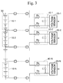
- An example of a conventional battery voltage detection device is shown in Fig. 3. As shown in this figure, in the conventional battery voltage detection device,
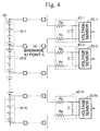
voltage sensors 20 are provided for each of themodules 10, and therebetween,noise filters 40 for eliminating noise are provided. For example, as shown in Fig. 4, in a battery voltage detection device having this kind of structure, when a voltage measuring line that carries the difference in voltage between modules to thevoltage sensors 20 is broken at point A, the voltage VA of the module 10-1 and the voltage VB of module 10-2 is divided by the capacitor of the noise filter, the voltage values V1 and V2 detected by voltage sensor 20-1 and voltage sensor 20-2 deviate from the actual values. - Specifically, the voltage values V1 and V2 detected by the voltage sensor 20-1 and the voltage sensor 20-2 are:
- In addition, under this condition, even if a voltage abnormality in a single module on the broken measuring line occurs, because both voltage values are averaged and an abnormality identification threshold value cannot be effectively used, the detection of an abnormality is difficult.
- In contrast, according to the structure of the present invention, by the voltage measuring line breakage detection resistors inserted before each noise filter, in the case that a breakage of the voltage measuring line occurs, the voltage that is in proportion to the resistance ratio of the voltage measurement breakage detection resistor, that is, the voltage value that differs significantly when compared to the normal value, is detected by the voltage sensor, and the breakage in the voltage measuring line can be detected immediately.
- In addition, simply by providing this resistor before the above-described noise filters, a complicated circuit becomes unnecessary, and thus breakage of the voltage measuring line can be detected at low cost.
- In addition, the measuring line breakage detection resister according to the above-described embodiment preferably is a resistor on the MΩ order.
- Because the above measuring line breakage detection resistor is a resistor that shorts each block, because this resistor value is large, the dark current can be reduced to a minimum, and the discharge of the battery during stand-by can be reduced to a minimum. As a result, at the measuring line breakage detection resistor, preferably the largest resistor value that is normally available should be selected.
- Furthermore, by using a resistor with a high resistance as the measuring line breakage detection resistor, the electric corrosion of the patterns, elements, etc., of the substrate of the battery voltage measuring device due to dark current can be avoided.
- In addition, in the present invention, the resistance ratio of the measuring line breakage detecting resistors corresponding to the adjacent blocks are set within a range of 1 : 1.5 to 1 : 3.
- By setting the resistance of the measuring line breakage detection resistor in this manner, when an abnormality such as a broken line occurs in the voltage measuring line, the voltage value of the block is divided by the resistance ratio set in the above-described range. Thereby, the value divided by the resistor does not become an extreme value with respect to the range actually used in the voltage sensor, but in addition, neither does it become a value of such a degree that the voltage sensor cannot detect an abnormality.
- As a result, a breakage in a voltage measuring line can be detected without undue overhead and quickly.
-
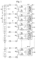
- Fig. 1 is a circuit diagram showing the structure of the battery voltage measuring device according to one embodiment of the present invention.
- Fig. 2 is a circuit diagram for explaining the operation of the battery voltage measuring device in the same embodiment.
- Fig. 3 is a circuit diagram showing the structure of a conventional battery voltage measuring device.
- Fig. 4 is a circuit diagram for explaining the operation of a conventional battery voltage measuring device.
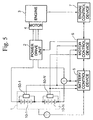
- Fig. 5 is a block diagram showing the entire structure of a parallel hybrid vehicle, which is one type of hybrid vehicles.
-
- Below, a preferred embodiment of the present invention will be explained with reference to the attached drawings. Fig. 1 is a block diagram showing the structure of the battery voltage measuring device according to one embodiment of the present invention. In this diagram,
reference numeral 30 denotes secondary batteries that are the object of measurement, andmodules 10 are formed by connecting a plurality ofbatteries 30 in series, and a plurality of modules 10 (10-1 to 10-N) are connected in series. Reference numeral 20 (20-1 to 20-N) denotes voltage sensors provided so as to correspond to each of the modules 10 (10-1 to 10-N), and are provided respectively on modules 10 (10-1 to 10-N) through noise filters 40 (40-1 to 40-N). - These
noise filters 40 are low pass filters simply constituted from the resistors and the capacitor. By providing this type of noise filter before a voltage sensor, thevoltage sensors 20 can measure the voltages in which the noise components have been eliminated. - In addition, between each of the noise filters 40 (40-1 to 40-N) and each of the modules 10 (10-1 to 10-N), resistors for detecting breakage of the voltage measuring line that carry the voltage between the module to the
voltage sensor 20 are connected in parallel. In addition, in resistors connected to the same voltage measuring line, resistors having differing resistances are connected. Specifically, as shown in Fig. 1, between the two resistors connected to the voltage measuring line Q, a 1 MΩ resistor is used for the voltage line breakage detection resistor 60-1, and a 2 MΩ resistor is used for the voltage line breakage detection resistor 60-2. In addition, similarly between two resistors connected to the voltage measuring line P, as described above, the voltage line breakage detector resistor 60-2 uses a 2 MΩ resistor, and the voltage line breakage detection resistor 60-3 uses a 1 MΩ resistor. In this manner, the resistors are connected such that the resistances alternate. Moreover, below, the determination of the resistance of the voltage linebreakage detection resistors 60 will be explained in detail. - Next, in the battery voltage measuring device according to the above-described construction, the case of breakage at point B of the voltage measuring line is explained referring to Fig. 2.
- First, in the battery voltage measuring device having the above-described construction, when the breakage occurs at point B, the voltages respectively detected at voltage sensors V1 and V2 are represented as follows, where the resistance of the voltage line breakage detecting resistor 60-1 is denoted by RA and the resistance of the voltage breakage line detecting resistor 60-2 is denoted by RB:
- In the above equations, VA is the actual voltage value of the module 10-1, and VB is the actual voltage value of the module 10-2.
- In this manner, the voltage V1 measured by the voltage sensor 20-1 and the voltage V2 measured by the voltage sensor 20-2 are values obtained by addition of the voltage VA of the module 10-1 and the voltage VB of the module 10-2, and by multiplying respective resistance ratios. Therefore, for example, in the case that the voltage line breakage detecting resistor 60-1 corresponding to module 10-1 is 1 MΩ and the voltage line breakage detection resistor 60-2 corresponding to the module 10-2 is 2 MΩ, substituting these values into the above equation (1) and equation (2) yields:
- Normally, in the battery group formed by connecting a plurality of secondary batteries in series, as shown in Fig. 1, the variance in the voltage between modules is within about 10% under such conditions as, for example, that the discharged current is small. Therefore, in the case that the voltage of each module detected by the voltage sensors exceeds a variance equal to or greater than 10%, an abnormal condition can be detected.
- As a result, the resistances of the measuring line breakage detecting resistors must be set so that when the voltage measuring line is broken, the voltages detected by the voltage sensors has a variance equal to or greater than 10%. Below, the method of setting the resistances of the measuring line breakage detecting resistors is explained in detail.
- First, in the case that each of the modules 10 (10-1 to 10-N) is required to have a capacity to output a maximum of 20 V, the voltage sensors 20 (20-1 to 20-N) that measure this voltage must have a capacity to measure up to this value with margin added. In the measuring system, in the case that the above-described measuring line breakage detection resistance ratio is 1 : 3, the voltage sensor for measuring line breakage detection must have a capacity to be able to measure up to 30 V.
- However, in the case that there is a necessity to measure voltage with high precision, it is not practical for the voltage sensor to have an extremely wide range with respect to the range of actual usage.
- In contrast, when the above-described measuring line breakage detecting resistance ratio of 1 : 1.5, because the voltage value to be detected by the voltage sensor changes only slightly for the case in which a breakage of the measuring line occurs and the case in which such a breakage does not occur, this will be treated as voltage variation under normal criteria, and the breakage of the measuring line cannot be detected.
- As a result, the measuring line breakage detecting resistance ratio must be set to the degree that an extremely large voltage is not generated with respect to the actual use range when a measuring line is broken, but at the same time set to a degree that the voltage value detected by the voltage sensor is not within the normal variance criteria for the voltage value for the cases in which a breakage of the measuring line occurs and the case in which it does not occur.
- In addition, this measuring line breakage detecting resistor is a resistor that shorts each module, and thus when this value becomes small, because there is concern about an increase in the dark current and electrolytic corrosion of the circuit pattern occur, a maximum resistance that is normally available, for example, 1 MΩ or 2 MΩ, is selected.
- It is noted that, although in the above-described embodiment, a case is explained in which each battery are formed by connecting a plurality of modules in series and each module is formed by connecting a plurality of cells in series, this can be applied to a battery formed by a single battery cell.
- Moreover, the present invention is not limited to the embodiment, but can be realized by appropriately altering the embodiment thereof without departing from the scope of the invention.
- Next, as an applied example of the voltage detecting device of the present invention, the case of an application to a voltage detector in the battery of a parallel hybrid vehicle will be explained referring to the attached drawings.
- Fig. 5 shows the schematic structure of a parallel hybrid vehicle. In this figure,
reference numeral 1 denotes a high voltage battery which is formed by modules 10 (10-1, 10-2, ...) having a plurality of cells connected in series serving as a unit, and these modules are further connected in series. In each module, battery voltage measuring devices 50 (50-1, 50-2, ...) that detect voltage are provided, and the voltage values of each module measured by the batteryvoltage measuring devices 50 are output to thebattery control device 5. - In addition, the current sensor that detects the current flowing in the
battery 1 and the temperature sensor that detects the temperature of thebattery 1 respectively detect the current and temperature at a predetermined timing, and output these values to thebattery control device 5. -
Reference numeral 2 denotes a power drive unit that is formed by three units of switching elements, such as IGBT, connected in parallel, wherein each unit is formed by two switching element connected in series. -
Reference numeral 3 denotes an engine that operates using the combustion energy of a fuel, and reference numeral 4 is an electrical motor used together with the engine and operating using electrical energy. The driving force of both theengine 3 and the motor 4 is transmitted to drive wheels (not illustrated) through a transmission (not illustrated) comprising automatic transmission or manual transmission. In addition, during deceleration of the hybrid vehicle, the drive force is transmitted from the drive wheels to the motor 4, the motor 4 generates what is termed regenerative braking force by functioning as a generator, and thebattery 1 is charged. It is noted, in addition to, but separate from the drive motor 4, the structure of the hybrid vehicle may provide a generator for charging thebattery 1. - The drive and regeneration of the motor 4 is carried out by the
power drive unit 2, which receives a control command from the motor control device 6. Specifically, by turning ON and OFF the switching elements in thepower drive unit 2 by the motor control device 6, the electric power from thebattery 1 is supplied to themotor 3 through three-phase wiring, and the regenerative electrical power of themotor 2 is supplied to thebattery 1. -
Reference numeral 5 denotes a battery control device that receives at predetermined timings the voltages (V1 to Vn) of each module that forms thebattery 1 from the voltage sensors 20 (20-1 to 20-N), the battery current Ibatt that flows through the battery from the current sensor, and the temperature Tbatt of thebattery 1 from the temperature sensor, and calculates the remaining charge SOC (state of charge, that is, the remaining battery charge) of thebattery 1 from these output values. -
Reference numeral 7 denotes an engine control device that monitors the engine speed NE, the vehicle speed, etc., at predetermined intervals, and determines whether the vehicle's mode is, for example, motor regeneration, assistance, or deceleration. In addition, at the same time, as a result of the determination of the above mode determination, theengine control device 7 determines the assistance/regeneration amount based on the state of charge SOC sent from thebattery control device 5. - Moreover, the
battery control device 5, the motor control device 6, and theengine control device 7 are formed by a CPU (central processing unit) and memory, and the functions thereof are realized by executing a program that realizes the functions of the control devices. - In a hybrid vehicle having the above-described structure, the battery
voltage measuring devices 50 provided in plurality on thebattery 1 are the battery voltage detection device of the present invention, and as shown in Fig. 1,voltage sensors 20 are, provided respectively on each module constructed by connecting in series a plurality of cells, and between each of themodules 10 and each of thevoltage sensors 20, a noise filter comprising a capacitor and resistors is interposed, and additionally, a measuring line breakage detection resistor is connected in parallel to each module. - In addition, the above-described voltage sensors 20 (20-1 to 20-N) measure the voltage of the modules 10 (10-1 to 10-N) based on continuous or periodic timing, and this measurement result is output to the
battery control device 5 at a predetermined timing. Here, in the case that the measuring line of the voltage measuring device is broken, the two voltage sensors having the broken measuring line measure the voltage (refer toequations 1 and 2) determined by the ratio of the respective measuring line breakage detecting resistors, and these voltages are output to thebattery control device 5. - When the
battery control device 5 receives the voltage of each module from each voltage sensor, first the variation of the received voltage values for each module is detected. At this time, if any of the measuring lines of the voltage measuring device are broken, the voltage values detected by the voltage sensor on this measuring line become values that deviate significantly from the voltage values of the other modules. As a result of this, the variation of the voltage of each module detected by thebattery control device 5 becomes comparatively larger than normal. - The
battery control device 5 determines the variation of the voltage of each of these modules, and when it determines that the variation is large in comparison to the normal variation, it detects that somewhere among the modules or batteryvoltage measuring devices 50 an abnormality has occurred, and outputs abnormality occurrence signals to the motor control device 6 and theengine control device 7, and then takes appropriate action towards the detected abnormality. - In contrast, in the case that the variation in voltage of the modules is determined to be in the normal range by the
battery control device 5, the voltage of all modules detected by voltage sensors 20 (20-1 to 20-N) are added, and the total voltage of thebattery 1 is calculated. In addition, when thebattery control device 5 receives the battery current Ibatt from the battery current sensor and the battery temperature Tbatt from the battery temperature sensor at the same timing, it calculates the state of charge SOC of thebattery 1 from the voltage, current, and temperature of this battery. - In addition, the
battery control device 5 outputs at a predetermined timing the calculated remaining charge SOC of thebattery 1 to the motor control device 6, and the motor control device 6 and theengine control device 7 respectively control the motor and engine using this state of charge SOC of thebattery 1 as one parameter for controlling the hybrid vehicle. - In this manner, because the voltage of
battery 1 can be accurately detected by the high precision batteryvoltage measuring devices 50 by detecting the voltage of the battery, the control of each component of the hybrid vehicle can also be carried out accurately. In addition, because the battery voltage measuring device of the present invention is small sized and low cost, cost reductions can be implemented by using this battery voltage measuring device. - As explained above, according to the battery voltage measuring device of the present invention, a voltage measuring line breakage detecting resistor is provided in parallel to each corresponding block. Thereby, in the case that a breakage in the voltage measuring line occurs, the voltage accompanying the resistance ratio of the voltage measuring line breakage detection resistor, that is, a voltage value that deviates significantly when compared to normal, is detected.
- Thereby, the effect is attained that the breakage in the voltage measuring line can be detected quickly.
- In addition, when carrying out breakage detection of the voltage measuring line, simply by providing a resistor, a complicated circuit is unnecessary, and thus the effect is attained that a breakage in the voltage measuring line can be detected at low cost.
- In addition, by using the measuring line breakage detecting resistor having a resistance in the MΩ order, the dark current can be reduced to a minimum, and the discharge of the battery during stand-by can be reduced to a minimum.
- In addition, the electrolytic corrosion of the pattern of the substrate and the elements of the battery voltage measuring device due to dark current can be avoided.
- The present invention provides a battery voltage measuring device capable of immediately detecting a breakage in the voltage measuring line in a battery voltage measuring device that detects the battery voltage. In blocks formed by connecting a plurality of secondary batteries in series, voltage sensors that detect the voltage of each block are respectively provided. In addition, before these voltage sensors noise filters are provided, and in addition, a measuring line breakage detecting resistor for detecting a breakage in the voltage measuring line is connected in parallel to each block. In a battery voltage measuring device having this type of structure, in the case that the voltage measuring line Q is broken, the voltage values V1 and V2 detected by the voltage sensors 20-1 and 20-2 become voltage values that accompany the resistance ratio of the measuring line breakage detecting resistors 60-1 and 60-2. Thereby, the voltage sensor detects a voltage that is not normally detected, and as a result, it becomes possible to immediately detect the breakage in the voltage measuring line.
Claims (2)
- A battery voltage measuring device in which a plurality of secondary batteries connected in series is divided into a plurality of blocks constituted of at least one secondary battery, and which measure the voltage of each block, comprising:a voltage measuring device provided on each of said blocks for measuring the voltage of said blocks;a noise filter provided before said voltage measuring device and having a capacitor; anda measuring line breakage detecting resistor, which is interposed between each of said blocks and said voltage measuring devices, and is connected in parallel to said blocks;
wherein the resistance ratio of the measuring line breakage detection resistors corresponding to adjacent blocks is set at the value in which the voltage value divided by said measuring line breakage detection resistors at the time of breakage of the measuring line becomes a voltage value not normally detected when the measuring line is not broken. - A battery voltage measuring device according to claim 1, wherein the resistance ratio of said measuring line breakage detection resistors corresponding to adjacent blocks is set within a range of 1 : 1.5 to 1 : 3.
Applications Claiming Priority (2)
| Application Number | Priority Date | Filing Date | Title |
|---|---|---|---|
| JP29747599A JP3300309B2 (en) | 1999-10-19 | 1999-10-19 | Battery voltage measuring device |
| JP29747599 | 1999-10-19 |
Publications (2)
| Publication Number | Publication Date |
|---|---|
| EP1094327A1 true EP1094327A1 (en) | 2001-04-25 |
| EP1094327B1 EP1094327B1 (en) | 2005-12-14 |
Family
ID=17846988
Family Applications (1)
| Application Number | Title | Priority Date | Filing Date |
|---|---|---|---|
| EP00121866A Expired - Lifetime EP1094327B1 (en) | 1999-10-19 | 2000-10-06 | Battery voltage measuring device |
Country Status (7)
| Country | Link |
|---|---|
| US (1) | US6255826B1 (en) |
| EP (1) | EP1094327B1 (en) |
| JP (1) | JP3300309B2 (en) |
| KR (1) | KR100355821B1 (en) |
| CN (1) | CN1140814C (en) |
| CA (1) | CA2322257C (en) |
| DE (1) | DE60024753T2 (en) |
Cited By (4)
| Publication number | Priority date | Publication date | Assignee | Title |
|---|---|---|---|---|
| EP1391962A1 (en) * | 2001-05-17 | 2004-02-25 | Sanyo Electric Co., Ltd. | Voltage measuring circuit of battery pack |
| DE10250520A1 (en) * | 2002-10-29 | 2004-05-19 | Cremer, Christian, Dipl.-Ing. | Fuel cell stack monitoring device, especially for automotive use, whereby impedances are switched together and then it is determined if a measured voltage value lies within a possible value range |
| EP2136219A3 (en) * | 2008-06-17 | 2011-10-19 | Sanyo Electric Co., Ltd. | Voltage detecting device of assembled battery and assembled battery system comprising same |
| WO2013104394A1 (en) * | 2012-01-13 | 2013-07-18 | Audi Ag | Battery arrangement for a motor vehicle |
Families Citing this family (96)
| Publication number | Priority date | Publication date | Assignee | Title |
|---|---|---|---|---|
| JP4034504B2 (en) * | 2000-07-31 | 2008-01-16 | アルプス電気株式会社 | Detection device |
| JP4019815B2 (en) * | 2002-06-26 | 2007-12-12 | 日産自動車株式会社 | Abnormality diagnosis apparatus and method for assembled battery |
| JP3539424B2 (en) * | 2002-07-24 | 2004-07-07 | 日産自動車株式会社 | Electric vehicle control device |
| JP4111150B2 (en) * | 2003-09-16 | 2008-07-02 | ブラザー工業株式会社 | Electronics |
| JP4103781B2 (en) * | 2003-11-19 | 2008-06-18 | トヨタ自動車株式会社 | Abnormality monitoring device in load drive circuit |
| US9496720B2 (en) | 2004-08-20 | 2016-11-15 | Midtronics, Inc. | System for automatically gathering battery information |
| KR100624944B1 (en) | 2004-11-29 | 2006-09-18 | 삼성에스디아이 주식회사 | Protect circuit of battery pack |
| JP4531608B2 (en) * | 2005-03-30 | 2010-08-25 | ルネサスエレクトロニクス株式会社 | Battery voltage measuring device |
| KR100669434B1 (en) | 2005-04-07 | 2007-01-15 | 삼성에스디아이 주식회사 | Method for controlling secondary battery module |
| JP4509852B2 (en) * | 2005-05-17 | 2010-07-21 | 株式会社東芝 | Battery assembly and voltage detector |
| JP4904729B2 (en) * | 2005-07-01 | 2012-03-28 | 日産自動車株式会社 | Cell voltage measuring device and fuel cell |
| KR100717789B1 (en) * | 2005-07-29 | 2007-05-11 | 삼성에스디아이 주식회사 | Method for estimating soc of secondary battery module |
| KR100739054B1 (en) | 2005-10-20 | 2007-07-12 | 삼성에스디아이 주식회사 | Battery management system and method for measuring cell voltage of the battery |
| KR100740097B1 (en) | 2005-10-20 | 2007-07-16 | 삼성에스디아이 주식회사 | Method of estimating SOC for battery and battery management system using the same |
| JP4620571B2 (en) * | 2005-11-21 | 2011-01-26 | ルネサスエレクトロニクス株式会社 | Battery voltage monitoring device |
| TWI280396B (en) * | 2005-12-26 | 2007-05-01 | Inventec Appliances Corp | Method for detecting a battery voltage with a high precision |
| JP4560501B2 (en) * | 2006-08-11 | 2010-10-13 | 矢崎総業株式会社 | Charge state adjustment device |
| KR100796668B1 (en) | 2006-09-26 | 2008-01-22 | 삼성에스디아이 주식회사 | Battery management system and driving method thereof |
| KR100859688B1 (en) | 2006-10-12 | 2008-09-23 | 삼성에스디아이 주식회사 | Battery management system and driving method thereof |
| KR100814884B1 (en) | 2006-10-16 | 2008-03-20 | 삼성에스디아이 주식회사 | Battery management system and driving method thereof |
| JP5210511B2 (en) * | 2006-10-26 | 2013-06-12 | 矢崎総業株式会社 | Anomaly detection device |
| KR100756976B1 (en) * | 2006-10-31 | 2007-09-07 | 주식회사 케피코 | Battery voltage measurement circuit and measuring method for battery voltage using the same |
| KR100839381B1 (en) | 2006-11-01 | 2008-06-20 | 삼성에스디아이 주식회사 | Battery management system and driving method thereof |
| JP5102483B2 (en) * | 2006-11-29 | 2012-12-19 | プライムアースEvエナジー株式会社 | Abnormality detection device, abnormality detection method, and abnormality detection program |
| JP4693761B2 (en) * | 2006-12-25 | 2011-06-01 | 株式会社東芝 | Assembled battery system |
| JP4864730B2 (en) | 2007-01-05 | 2012-02-01 | ルネサスエレクトロニクス株式会社 | Battery voltage monitoring device |
| KR100882913B1 (en) | 2007-03-19 | 2009-02-10 | 삼성에스디아이 주식회사 | Battery Pack |
| JP4104648B1 (en) * | 2007-09-13 | 2008-06-18 | 和征 榊原 | Battery pack |
| US7852047B2 (en) * | 2007-09-20 | 2010-12-14 | Denso Corporation | Disconnection detection device of assembled battery system and disconnection detection method of same |
| JP4649464B2 (en) * | 2007-11-29 | 2011-03-09 | 本田技研工業株式会社 | Battery voltage detector |
| DE102007061539A1 (en) * | 2007-12-20 | 2009-07-02 | Continental Automotive Gmbh | Monitoring circuit for an energy storage and method for monitoring an energy storage |
| JP4216898B1 (en) * | 2008-03-28 | 2009-01-28 | 和征 榊原 | Battery pack |
| JP5169491B2 (en) * | 2008-05-28 | 2013-03-27 | 株式会社Gsユアサ | Battery pack monitoring device and battery breakage detection method |
| JP4775415B2 (en) * | 2008-07-14 | 2011-09-21 | Tdk株式会社 | Voltage monitor circuit |
| ES2395695T3 (en) | 2009-03-18 | 2013-02-14 | Vito Nv | Power cell system with means to detect a discontinuity |
| JP2010271267A (en) * | 2009-05-25 | 2010-12-02 | Mitsubishi Motors Corp | Battery monitoring device |
| JP5535531B2 (en) * | 2009-06-25 | 2014-07-02 | 矢崎総業株式会社 | Disconnection detector |
| US8957610B2 (en) * | 2009-07-02 | 2015-02-17 | Chong Uk Lee | Multi-port reconfigurable battery |
| US8816613B2 (en) * | 2009-07-02 | 2014-08-26 | Chong Uk Lee | Reconfigurable battery |
| US9588185B2 (en) | 2010-02-25 | 2017-03-07 | Keith S. Champlin | Method and apparatus for detecting cell deterioration in an electrochemical cell or battery |
| US9425487B2 (en) | 2010-03-03 | 2016-08-23 | Midtronics, Inc. | Monitor for front terminal batteries |
| JP4602471B1 (en) | 2010-04-14 | 2010-12-22 | 和征 榊原 | Battery pack and battery pack system |
| US11740294B2 (en) | 2010-06-03 | 2023-08-29 | Midtronics, Inc. | High use battery pack maintenance |
| US10046649B2 (en) | 2012-06-28 | 2018-08-14 | Midtronics, Inc. | Hybrid and electric vehicle battery pack maintenance device |
| DE112011101892T5 (en) | 2010-06-03 | 2013-03-21 | Midtronics, Inc. | Battery pack maintenance for electric vehicles |
| CN102918410B (en) * | 2010-06-04 | 2014-11-26 | 丰田自动车株式会社 | Secondary battery, secondary battery test device and method, and battery test system |
| JP5911673B2 (en) * | 2010-07-30 | 2016-04-27 | 三洋電機株式会社 | Power supply |
| DE102010040713A1 (en) | 2010-09-14 | 2012-03-15 | Sb Limotive Company Ltd. | Battery with detection of cell voltages and battery current and only one potential separation device |
| JP5705556B2 (en) * | 2011-01-11 | 2015-04-22 | ラピスセミコンダクタ株式会社 | Semiconductor circuit, semiconductor device, disconnection detection method, and disconnection detection program |
| JP5353914B2 (en) * | 2011-02-01 | 2013-11-27 | 株式会社デンソー | Battery voltage monitoring device |
| JP5353915B2 (en) | 2011-02-01 | 2013-11-27 | 株式会社デンソー | Battery voltage monitoring device |
| DE102011079363A1 (en) * | 2011-07-19 | 2013-01-24 | Sb Limotive Company Ltd. | Apparatus and method for measuring a minimum cell voltage |
| DE102011079360A1 (en) * | 2011-07-19 | 2013-01-24 | Sb Limotive Company Ltd. | Device and method for measuring a maximum cell voltage |
| JP5652355B2 (en) * | 2011-08-30 | 2015-01-14 | 株式会社Gsユアサ | Battery pack monitoring device and battery pack |
| JP5602114B2 (en) * | 2011-09-06 | 2014-10-08 | 三菱自動車工業株式会社 | Battery management device, battery management system |
| WO2013070850A2 (en) | 2011-11-10 | 2013-05-16 | Midtronics, Inc. | Battery pack tester |
| JP5602167B2 (en) * | 2012-02-21 | 2014-10-08 | オムロンオートモーティブエレクトロニクス株式会社 | Battery monitoring device |
| JP5989375B2 (en) | 2012-03-28 | 2016-09-07 | ラピスセミコンダクタ株式会社 | Semiconductor device and battery monitoring system |
| US11325479B2 (en) | 2012-06-28 | 2022-05-10 | Midtronics, Inc. | Hybrid and electric vehicle battery maintenance device |
| US9851411B2 (en) * | 2012-06-28 | 2017-12-26 | Keith S. Champlin | Suppressing HF cable oscillations during dynamic measurements of cells and batteries |
| JP5811062B2 (en) * | 2012-08-02 | 2015-11-11 | 株式会社豊田自動織機 | Voltage monitoring device |
| JP6127437B2 (en) * | 2012-10-12 | 2017-05-17 | 静岡製機株式会社 | Combustion control device |
| JP5870899B2 (en) * | 2012-10-30 | 2016-03-01 | 株式会社デンソー | Battery monitoring device |
| WO2014075630A1 (en) * | 2012-11-19 | 2014-05-22 | Shenzhen Byd Auto R & D Company Limited | Protective device and protective system for battery assembly |
| JP2014126437A (en) * | 2012-12-26 | 2014-07-07 | Denso Corp | Battery monitoring device |
| US10106038B2 (en) | 2012-12-28 | 2018-10-23 | Johnson Controls Technology Company | Dual function battery system and method |
| US10084214B2 (en) * | 2013-03-15 | 2018-09-25 | Atieva, Inc. | Automatic switchover from cell voltage to interconnect voltage monitoring |
| CN105164541B (en) * | 2013-04-26 | 2018-04-06 | 日立汽车系统株式会社 | Battery monitoring apparatus and the battery system using the battery monitoring apparatus |
| US9770997B2 (en) | 2013-06-11 | 2017-09-26 | Ford Global Technologies, Llc | Detection of imbalance across multiple battery cells measured by the same voltage sensor |
| JP6253270B2 (en) | 2013-06-14 | 2017-12-27 | ラピスセミコンダクタ株式会社 | Battery monitoring system, semiconductor circuit, disconnection detection program, and disconnection detection method |
| JP6016754B2 (en) * | 2013-11-15 | 2016-10-26 | オムロンオートモーティブエレクトロニクス株式会社 | Battery voltage detector |
| JP6040916B2 (en) * | 2013-11-19 | 2016-12-07 | 株式会社デンソー | Disconnection detector |
| US10843574B2 (en) | 2013-12-12 | 2020-11-24 | Midtronics, Inc. | Calibration and programming of in-vehicle battery sensors |
| EP2897229A1 (en) | 2014-01-16 | 2015-07-22 | Midtronics, Inc. | Battery clamp with endoskeleton design |
| JP6201778B2 (en) * | 2014-01-17 | 2017-09-27 | 株式会社ケーヒン | Voltage detector |
| CN104808078A (en) * | 2014-01-29 | 2015-07-29 | 陕西汽车集团有限责任公司 | Test system for battery management system function test |
| US10473555B2 (en) | 2014-07-14 | 2019-11-12 | Midtronics, Inc. | Automotive maintenance system |
| US10222397B2 (en) | 2014-09-26 | 2019-03-05 | Midtronics, Inc. | Cable connector for electronic battery tester |
| WO2016123075A1 (en) | 2015-01-26 | 2016-08-04 | Midtronics, Inc. | Alternator tester |
| US9966676B2 (en) | 2015-09-28 | 2018-05-08 | Midtronics, Inc. | Kelvin connector adapter for storage battery |
| JP6398964B2 (en) | 2015-12-15 | 2018-10-03 | 株式会社デンソー | Battery pack monitoring system |
| US10608353B2 (en) | 2016-06-28 | 2020-03-31 | Midtronics, Inc. | Battery clamp |
| US11054480B2 (en) | 2016-10-25 | 2021-07-06 | Midtronics, Inc. | Electrical load for electronic battery tester and electronic battery tester including such electrical load |
| WO2019069390A1 (en) * | 2017-10-04 | 2019-04-11 | 日産自動車株式会社 | Battery pack inspection method and inspection device |
| JP6958267B2 (en) * | 2017-11-10 | 2021-11-02 | トヨタ自動車株式会社 | car |
| US11005276B2 (en) | 2018-01-23 | 2021-05-11 | Solsona Enterprise, Llc | Stacked variable voltage battery module arrangement |
| CN108896902B (en) * | 2018-06-12 | 2020-11-10 | 广州小鹏汽车科技有限公司 | BMS single acquisition circuit fault diagnosis circuit, system and method |
| CN110907056A (en) * | 2018-09-14 | 2020-03-24 | 宁德时代新能源科技股份有限公司 | Battery pack temperature detection system |
| US11513160B2 (en) | 2018-11-29 | 2022-11-29 | Midtronics, Inc. | Vehicle battery maintenance device |
| US11418041B2 (en) | 2019-03-15 | 2022-08-16 | Lg Energy Solution, Ltd. | Battery system |
| US11566972B2 (en) | 2019-07-31 | 2023-01-31 | Midtronics, Inc. | Tire tread gauge using visual indicator |
| US11545839B2 (en) | 2019-11-05 | 2023-01-03 | Midtronics, Inc. | System for charging a series of connected batteries |
| US11668779B2 (en) | 2019-11-11 | 2023-06-06 | Midtronics, Inc. | Hybrid and electric vehicle battery pack maintenance device |
| US11474153B2 (en) | 2019-11-12 | 2022-10-18 | Midtronics, Inc. | Battery pack maintenance system |
| US11486930B2 (en) | 2020-01-23 | 2022-11-01 | Midtronics, Inc. | Electronic battery tester with battery clamp storage holsters |
| GB202011897D0 (en) | 2020-07-30 | 2020-09-16 | Cummins Inc | Detecting thermal events in battery packs |
Citations (2)
| Publication number | Priority date | Publication date | Assignee | Title |
|---|---|---|---|---|
| US5578927A (en) * | 1993-12-09 | 1996-11-26 | Saft | Measurement circuit for a modular system of cells electrically connected in series, in particular for electrical accumlator batteries |
| EP0932240A2 (en) * | 1997-12-26 | 1999-07-28 | Hitachi, Ltd. | Battery system and electric vehicle using the battery system |
Family Cites Families (6)
| Publication number | Priority date | Publication date | Assignee | Title |
|---|---|---|---|---|
| US4383211A (en) | 1981-01-02 | 1983-05-10 | Atlantic Richfield Company | Electrical charging and discharging control apparatus and method, and solar to electrical energy conversion apparatus incorporating such apparatus |
| CA2034824A1 (en) | 1991-01-23 | 1992-07-24 | John Alan Gibson | Current harmonic, current form factor and power factor modification unit for rectifier supplied loads |
| KR100213760B1 (en) * | 1996-10-16 | 1999-08-02 | 오상수 | Battery charge system for hybrid vehicle |
| KR100204272B1 (en) * | 1996-12-27 | 1999-06-15 | 양재신 | Leakage intercepter of electric car battery |
| KR200316732Y1 (en) * | 1998-11-13 | 2003-08-19 | 발레오만도전장시스템스코리아 주식회사 | Voltage regulator of car generator |
| KR20000040537A (en) * | 1998-12-18 | 2000-07-05 | 윤종용 | Battery check device |
-
1999
- 1999-10-19 JP JP29747599A patent/JP3300309B2/en not_active Expired - Fee Related
-
2000
- 2000-10-04 CA CA002322257A patent/CA2322257C/en not_active Expired - Fee Related
- 2000-10-06 DE DE60024753T patent/DE60024753T2/en not_active Expired - Lifetime
- 2000-10-06 EP EP00121866A patent/EP1094327B1/en not_active Expired - Lifetime
- 2000-10-09 KR KR1020000059279A patent/KR100355821B1/en not_active IP Right Cessation
- 2000-10-17 US US09/688,383 patent/US6255826B1/en not_active Expired - Lifetime
- 2000-10-19 CN CNB001314319A patent/CN1140814C/en not_active Expired - Fee Related
Patent Citations (2)
| Publication number | Priority date | Publication date | Assignee | Title |
|---|---|---|---|---|
| US5578927A (en) * | 1993-12-09 | 1996-11-26 | Saft | Measurement circuit for a modular system of cells electrically connected in series, in particular for electrical accumlator batteries |
| EP0932240A2 (en) * | 1997-12-26 | 1999-07-28 | Hitachi, Ltd. | Battery system and electric vehicle using the battery system |
Cited By (5)
| Publication number | Priority date | Publication date | Assignee | Title |
|---|---|---|---|---|
| EP1391962A1 (en) * | 2001-05-17 | 2004-02-25 | Sanyo Electric Co., Ltd. | Voltage measuring circuit of battery pack |
| EP1391962A4 (en) * | 2001-05-17 | 2005-10-12 | Sanyo Electric Co | Voltage measuring circuit of battery pack |
| DE10250520A1 (en) * | 2002-10-29 | 2004-05-19 | Cremer, Christian, Dipl.-Ing. | Fuel cell stack monitoring device, especially for automotive use, whereby impedances are switched together and then it is determined if a measured voltage value lies within a possible value range |
| EP2136219A3 (en) * | 2008-06-17 | 2011-10-19 | Sanyo Electric Co., Ltd. | Voltage detecting device of assembled battery and assembled battery system comprising same |
| WO2013104394A1 (en) * | 2012-01-13 | 2013-07-18 | Audi Ag | Battery arrangement for a motor vehicle |
Also Published As
| Publication number | Publication date |
|---|---|
| CN1140814C (en) | 2004-03-03 |
| CN1293370A (en) | 2001-05-02 |
| CA2322257C (en) | 2002-12-03 |
| JP3300309B2 (en) | 2002-07-08 |
| CA2322257A1 (en) | 2001-04-19 |
| JP2001116776A (en) | 2001-04-27 |
| KR100355821B1 (en) | 2002-10-19 |
| DE60024753D1 (en) | 2006-01-19 |
| US6255826B1 (en) | 2001-07-03 |
| EP1094327B1 (en) | 2005-12-14 |
| DE60024753T2 (en) | 2006-07-06 |
| KR20010040039A (en) | 2001-05-15 |
Similar Documents
| Publication | Publication Date | Title |
|---|---|---|
| EP1094327B1 (en) | Battery voltage measuring device | |
| US9519027B2 (en) | Battery monitoring device and battery system monitoring device | |
| US9568557B2 (en) | Battery monitoring device and battery system monitoring device | |
| US9459324B2 (en) | Device and method for the redundant determination of a battery current flowing through the poles of a battery | |
| US7554291B2 (en) | Battery control system for a chargeable-and-dischargeable power supply system | |
| US6437538B1 (en) | Battery voltage measurement apparatus | |
| EP3575809B1 (en) | A method of operating battery management systems, corresponding device and vehicle | |
| US20160233700A1 (en) | Battery monitor apparatus | |
| US9921270B2 (en) | Battery system with cell voltage detecting units | |
| US11493564B2 (en) | Ground fault detection device | |
| CN107889526B (en) | Battery system monitoring device | |
| JP4171449B2 (en) | Power supply for vehicle | |
| JP6706688B2 (en) | Battery control device | |
| US11073571B2 (en) | Ground fault detection apparatus | |
| JPWO2006064786A1 (en) | Power supply | |
| US20220097566A1 (en) | Cell Balancing Device | |
| JP2017070024A (en) | Battery monitoring device | |
| KR101854456B1 (en) | Battery Sensor and Battery Monitoring System | |
| US7999553B2 (en) | Voltage measurement device and electric vehicle | |
| JP2015102336A (en) | Battery monitoring device | |
| JP4389758B2 (en) | Cell voltage variation abnormality detection device | |
| WO2017006668A1 (en) | Battery monitoring device | |
| JP2000060011A (en) | State detecting method of assembled battery and state detecting equipment | |
| US20220155376A1 (en) | Battery Apparatus and Current Sensor Diagnosis Method | |
| EP4332586A1 (en) | Device for measuring insulation resistance and battery system including same |
Legal Events
| Date | Code | Title | Description |
|---|---|---|---|
| PUAI | Public reference made under article 153(3) epc to a published international application that has entered the european phase |
Free format text: ORIGINAL CODE: 0009012 |
|
| AK | Designated contracting states |
Kind code of ref document: A1 Designated state(s): DE FR GB |
|
| AX | Request for extension of the european patent |
Free format text: AL;LT;LV;MK;RO;SI |
|
| 17P | Request for examination filed |
Effective date: 20010618 |
|
| AKX | Designation fees paid |
Free format text: DE FR GB |
|
| 17Q | First examination report despatched |
Effective date: 20040512 |
|
| GRAP | Despatch of communication of intention to grant a patent |
Free format text: ORIGINAL CODE: EPIDOSNIGR1 |
|
| GRAS | Grant fee paid |
Free format text: ORIGINAL CODE: EPIDOSNIGR3 |
|
| GRAA | (expected) grant |
Free format text: ORIGINAL CODE: 0009210 |
|
| AK | Designated contracting states |
Kind code of ref document: B1 Designated state(s): DE FR GB |
|
| REG | Reference to a national code |
Ref country code: GB Ref legal event code: FG4D |
|
| REF | Corresponds to: |
Ref document number: 60024753 Country of ref document: DE Date of ref document: 20060119 Kind code of ref document: P |
|
| ET | Fr: translation filed | ||
| PLBE | No opposition filed within time limit |
Free format text: ORIGINAL CODE: 0009261 |
|
| STAA | Information on the status of an ep patent application or granted ep patent |
Free format text: STATUS: NO OPPOSITION FILED WITHIN TIME LIMIT |
|
| 26N | No opposition filed |
Effective date: 20060915 |
|
| PGFP | Annual fee paid to national office [announced via postgrant information from national office to epo] |
Ref country code: DE Payment date: 20121003 Year of fee payment: 13 Ref country code: FR Payment date: 20121018 Year of fee payment: 13 |
|
| PGFP | Annual fee paid to national office [announced via postgrant information from national office to epo] |
Ref country code: GB Payment date: 20121003 Year of fee payment: 13 |
|
| GBPC | Gb: european patent ceased through non-payment of renewal fee |
Effective date: 20131006 |
|
| PG25 | Lapsed in a contracting state [announced via postgrant information from national office to epo] |
Ref country code: GB Free format text: LAPSE BECAUSE OF NON-PAYMENT OF DUE FEES Effective date: 20131006 |
|
| REG | Reference to a national code |
Ref country code: FR Ref legal event code: ST Effective date: 20140630 |
|
| REG | Reference to a national code |
Ref country code: DE Ref legal event code: R119 Ref document number: 60024753 Country of ref document: DE Effective date: 20140501 |
|
| PG25 | Lapsed in a contracting state [announced via postgrant information from national office to epo] |
Ref country code: DE Free format text: LAPSE BECAUSE OF NON-PAYMENT OF DUE FEES Effective date: 20140501 Ref country code: FR Free format text: LAPSE BECAUSE OF NON-PAYMENT OF DUE FEES Effective date: 20131031 |