EP1095901A1 - Food dispensing apparatus - Google Patents
Food dispensing apparatus Download PDFInfo
- Publication number
- EP1095901A1 EP1095901A1 EP00124876A EP00124876A EP1095901A1 EP 1095901 A1 EP1095901 A1 EP 1095901A1 EP 00124876 A EP00124876 A EP 00124876A EP 00124876 A EP00124876 A EP 00124876A EP 1095901 A1 EP1095901 A1 EP 1095901A1
- Authority
- EP
- European Patent Office
- Prior art keywords
- container
- housing
- containers
- dispensing
- food
- Prior art date
- Legal status (The legal status is an assumption and is not a legal conclusion. Google has not performed a legal analysis and makes no representation as to the accuracy of the status listed.)
- Withdrawn
Links
Images


Classifications
-
- A—HUMAN NECESSITIES
- A23—FOODS OR FOODSTUFFS; TREATMENT THEREOF, NOT COVERED BY OTHER CLASSES
- A23G—COCOA; COCOA PRODUCTS, e.g. CHOCOLATE; SUBSTITUTES FOR COCOA OR COCOA PRODUCTS; CONFECTIONERY; CHEWING GUM; ICE-CREAM; PREPARATION THEREOF
- A23G9/00—Frozen sweets, e.g. ice confectionery, ice-cream; Mixtures therefor
- A23G9/04—Production of frozen sweets, e.g. ice-cream
- A23G9/22—Details, component parts or accessories of apparatus insofar as not peculiar to a single one of the preceding groups
- A23G9/28—Details, component parts or accessories of apparatus insofar as not peculiar to a single one of the preceding groups for portioning or dispensing
- A23G9/281—Details, component parts or accessories of apparatus insofar as not peculiar to a single one of the preceding groups for portioning or dispensing at the discharge end of freezing chambers
- A23G9/283—Details, component parts or accessories of apparatus insofar as not peculiar to a single one of the preceding groups for portioning or dispensing at the discharge end of freezing chambers for filling containers with material
-
- A—HUMAN NECESSITIES
- A23—FOODS OR FOODSTUFFS; TREATMENT THEREOF, NOT COVERED BY OTHER CLASSES
- A23G—COCOA; COCOA PRODUCTS, e.g. CHOCOLATE; SUBSTITUTES FOR COCOA OR COCOA PRODUCTS; CONFECTIONERY; CHEWING GUM; ICE-CREAM; PREPARATION THEREOF
- A23G3/00—Sweetmeats; Confectionery; Marzipan; Coated or filled products
- A23G3/02—Apparatus specially adapted for manufacture or treatment of sweetmeats or confectionery; Accessories therefor
- A23G3/28—Apparatus for decorating sweetmeats or confectionery
-
- A—HUMAN NECESSITIES
- A23—FOODS OR FOODSTUFFS; TREATMENT THEREOF, NOT COVERED BY OTHER CLASSES
- A23G—COCOA; COCOA PRODUCTS, e.g. CHOCOLATE; SUBSTITUTES FOR COCOA OR COCOA PRODUCTS; CONFECTIONERY; CHEWING GUM; ICE-CREAM; PREPARATION THEREOF
- A23G9/00—Frozen sweets, e.g. ice confectionery, ice-cream; Mixtures therefor
- A23G9/04—Production of frozen sweets, e.g. ice-cream
- A23G9/22—Details, component parts or accessories of apparatus insofar as not peculiar to a single one of the preceding groups
- A23G9/28—Details, component parts or accessories of apparatus insofar as not peculiar to a single one of the preceding groups for portioning or dispensing
-
- B—PERFORMING OPERATIONS; TRANSPORTING
- B65—CONVEYING; PACKING; STORING; HANDLING THIN OR FILAMENTARY MATERIAL
- B65D—CONTAINERS FOR STORAGE OR TRANSPORT OF ARTICLES OR MATERIALS, e.g. BAGS, BARRELS, BOTTLES, BOXES, CANS, CARTONS, CRATES, DRUMS, JARS, TANKS, HOPPERS, FORWARDING CONTAINERS; ACCESSORIES, CLOSURES, OR FITTINGS THEREFOR; PACKAGING ELEMENTS; PACKAGES
- B65D83/00—Containers or packages with special means for dispensing contents
- B65D83/0055—Containers or packages provided with a flexible bag or a deformable membrane or diaphragm for expelling the contents
- B65D83/0072—Containers or packages provided with a flexible bag or a deformable membrane or diaphragm for expelling the contents the contents of a flexible bag being expelled by a piston or a movable bottom or partition provided in the container or the package
-
- B—PERFORMING OPERATIONS; TRANSPORTING
- B67—OPENING, CLOSING OR CLEANING BOTTLES, JARS OR SIMILAR CONTAINERS; LIQUID HANDLING
- B67D—DISPENSING, DELIVERING OR TRANSFERRING LIQUIDS, NOT OTHERWISE PROVIDED FOR
- B67D1/00—Apparatus or devices for dispensing beverages on draught
- B67D1/0001—Apparatus or devices for dispensing beverages on draught by squeezing collapsible or flexible storage containers
-
- B—PERFORMING OPERATIONS; TRANSPORTING
- B65—CONVEYING; PACKING; STORING; HANDLING THIN OR FILAMENTARY MATERIAL
- B65D—CONTAINERS FOR STORAGE OR TRANSPORT OF ARTICLES OR MATERIALS, e.g. BAGS, BARRELS, BOTTLES, BOXES, CANS, CARTONS, CRATES, DRUMS, JARS, TANKS, HOPPERS, FORWARDING CONTAINERS; ACCESSORIES, CLOSURES, OR FITTINGS THEREFOR; PACKAGING ELEMENTS; PACKAGES
- B65D85/00—Containers, packaging elements or packages, specially adapted for particular articles or materials
- B65D85/70—Containers, packaging elements or packages, specially adapted for particular articles or materials for materials not otherwise provided for
- B65D85/72—Containers, packaging elements or packages, specially adapted for particular articles or materials for materials not otherwise provided for for edible or potable liquids, semiliquids, or plastic or pasty materials
- B65D85/78—Containers, packaging elements or packages, specially adapted for particular articles or materials for materials not otherwise provided for for edible or potable liquids, semiliquids, or plastic or pasty materials for ice-cream
Definitions
- This invention relates to dispensing apparatus for dispensing a viscous or semi-solid product from a container.
- An object of the invention is to provide dispensing apparatus especially suitable for food products which is simple, adaptable and hygienic.
- dispensing apparatus for dispensing a viscous or semi-solid product from a container comprising a base, a deformable portion and an outlet, the apparatus comprising deforming means movable to engage and deform the deformable portion to discharge product from the container through the outlet, a seating for supporting the base of the container during dispensing of product from the container, an arm carrying the seating and movable between an operating position and a non-operating position in which the container may be removed from and placed in the seating, and support means for the arm whereby the arm is movable between said positions, the deforming means being engageable with the container only in the operating position.
- the deforming means is a plunger movable in a generally vertical direction, and the seating, in the operating position, is located vertically below the plunger, the arm and the seating being movable about a generally horizontal axis of the support means to a non-operating position to one side of the operating position.
- the seating and the arm are presented generally horizontally in the operating position and downwardly inclined to the horizontal in the non-operating position.
- the seating and the arm are releasably securable in each of the operating and non-operating positions and the plunger is movable only when the seating is in the operating position.
- the arm may be L-shaped and located in an inverted position, the shorter limb of the arm carrying the seating, and pivot means is located towards the lower end of the longer limb of the arm.
- the arm may have a handle whereby the arm is movable manually between the operating and non-operating positions, and the seating is arranged for the container to be lifted up and out of the seating, the deformable portion of the container being presented upwardly towards the plunger and the outlet being presented downwardly from the arm when the container is located in the seating.
- the apparatus may include an upright frame having towards its upper end a support for the deforming means and its associated drive means, the frame having intermediate its ends the arm and associated seating, and the frame having towards its lower end a base for supporting the frame, the base including a receiver spaced below the seating and giving access to a receptacle for product discharged from the container.
- the frame houses drive means for the deforming means and lighting means, and a housing surrounds the lighting means and has a light transmission region for lighting the housing from within.
- the deforming means may be driven by a compressed gas operated piston and cylinder arrangement, and the apparatus includes a source of compressed gas and gas reservoir for supplying pressurised gas to the piston and cylinder.
- the deforming means includes locating means movable to engage with the container to locate the container in the seating, and pressure generating means which engages with the deformable portion of the container to deform the portion towards the base in discharging product through the container outlet and the locating means and the pressure generating means are relatively movable so that, after the locating means has engaged the container, the pressure generating means moves relative to the locating means to discharge said product.
- the locating means may comprise a locating member slidably mounted relative to the pressure generating means and resiliently urged by spring means towards a locating position, whereby after said member locates with the container the pressure generating means moves against the action of the spring means to deform the deformable portion of the container and the pressure generating means comprises a plunger head which is shaped to correspond with the internal shape of the base of the container.
- the locating member may be powered towards a locating position independently of operation of the pressure generating means.
- the plunger head is generally cylindrical with curvilinear surfaces at its region which engages the deformable portion of the container.
- the seating is a cup-shaped member arranged to receive a correspondingly-shaped base of the container, the seating having a central opening through which the container outlet is directed when the container is placed in the seating, the container being liftable out of the seating after a dispensing action, and the seating being removable from the arm.
- the seating member may be secured permanently on the arm.
- dispensing apparatus for dispensing a viscous or semi-solid product from a container comprising a base, a deformable portion and an outlet
- the apparatus comprising deforming means arranged to deform the container to discharge product from the container through the outlet, the deforming means including locating means movable to engage with the container to locate the container, and a plunger which engages with the deformable portion of the container to deform the portion towards the base in discharging product through said outlet, the locating means and the plunger being relatively movable so that, after the locating means has engaged the container, the plunger moves relative to the locating means to discharge said product.
- the invention provides dispensing apparatus for dispensing a viscous or semi-solid product from a container having a base, a deformable portion and an outlet, the apparatus comprising deforming means arranged to deform the deformable portion to discharge product from the container through the outlet, drive means for the deforming means, a seating for supporting the container, a frame on which the deforming means, the drive means and the seating are supported, the frame also housing a reservoir for compressed gas providing a source of compressed gas for operating the drive means.
- the invention also provides a container for use with the dispensing apparatus comprising a base for receiving product to be dispensed, an outlet opening for discharge of product, a closure member or lid for closing the base after admitting product to the base, a deformable region of the closure member arranged to deform upon engagement by deforming means and to be moved towards the base to discharge product from the outlet, the closure member and the base each being nestable with other closure members and bases respectively when separate from one another, the base having upper and lower regions arranged so that when assembled the deformable region of the closure member extends into the upper region of the base and, upon deformation of the deformable region, the deformable region enters and moves to adjacent the internal surfaces of the lower region of the base, the base being of relatively rigid material compared with the deformable region.
- the closure member extends towards its outer part to adjacent the shoulder, the closure member having inwardly of the outer part a domed region which, in use, is engaged and deformed by the deforming member towards the lower region of the base.
- the outer region of the top part may include a turned over lip whereby the top portion is secured to the base part by the turned over lip engaging with the upper edge of the base part when the top part and the base part are assembled together after the base part is filled with product.
- the container parts are conveniently formed of plastics by injection moulding, by thermoforming or by blow moulding or they may be of paper or cardboard which may be coated with plastic.
- the dispensing apparatus may have a manually or power-operated drive means which causes the deforming means in the form of a plunger to be reciprocally movable towards and away from a container in a dispensing operation of the apparatus.
- the drive means may be electrically, hydraulically or gas operated.
- the arm is pivotable between a product discharge position and a container location position by pivoting through about 40-60° from a horizontal discharge position so that the support is presented to a better viewing position to the operative.
- a manually movable lever to which a shaft is attached for rotation therewith, and a linkage carried on the shaft is connected to a rod on one end of which is mounted the plunger.
- the plunger is movable along and guided by a cylinder arranged vertically and above a container locating position.
- a storage compartment for containers with, if required, refrigeration means for maintaining the containers at the desired dispensing temperature.
- the central deformable region is connected to the outer region through an integral flexible folded portion.
- the folded portion may have downwardly and upwardly directed folds one of which lies closely adjacent an inner surface of the base part when assembled therewith and the junction between the downward and upward folds preferably lying half way down the base part when assembled.
- the central region includes a generally planar portion and the base part is of generally circular section.
- dispensing apparatus for a dispensing system is manually operated and includes a vertically arranged frame 10 having a base 11 on which may be supported a receptacle (not shown) for product.
- the frame 10 includes upwardly extending frame members 12 at the uppermost end of which are mounted horizontal support arms 13. Between the arms 13 is rotatably mounted a shaft 14 on one end of which is carried for rotation therewith a lever 15.
- the lever 15 is movable between an upper inoperative position 15' through an intermediate position 15'' and a lower position 15'''.
- a linkage assembly 17 including a pair of links 18 rotatably carried on the shaft 14. At the opposite ends of the links 18 is carried a spindle 19, the links 18 being pivotable relative to the spindle 19, and a further pair of links 20 depend from and are pivotally mounted on the spindle 19.
- linkage shown other arrangements can be used such as a double cantilever arrangement, so that downward pressure on the plunger 36 is always in the vertical direction.
- the further links 20 are interconnected at their lower ends by a spindle 22 which extends through the upper end of a rod 23 which is the operating rod of a plunger assembly 24 (shown in more detail in Fig. 3).
- the spindle 22 is rotatably mounted in a bore 25 in the rod 23.
- the plunger assembly 24 includes a cylinder 26 which is mounted on the frame 10 by vertically arranged plates 27 attached at their upper ends to the beam 13 and towards their lower ends to brackets 28 secured to the uprights 12.
- the brackets 28 and plates 27 are interconnected and together provide a support for the cylinder 26.
- the cylinder 26 is open ended and receives coaxially the rod 23.
- the rod 23 carries fixed thereto an upper annular member 29 which fits within and for movement along the inner walls of the cylinder 26.
- a generally cup-shaped member 30 Spaced downwardly from the annular member 29 and along the rod 23, and axially movable relative to the rod 23, is a generally cup-shaped member 30 comprising a further annular member 31 secured to a locating member 32 extending downwardly from the member 31 and defining an inner cylindrical bore 33.
- Towards the lower end of the member 32 is an annular tapered locating portion 34 which is spaced from the inner walls of the cylinder 26.
- an engagement member or plunger head 36 Carried at the lower end of the rod 23 is an engagement member or plunger head 36 secured for movement with the rod 23 along the cylinder 33.
- the lower end of the plunger 36 is formed with a flat surface 37 bounded by a curved periphery 38.
- a spring 40 Engaging between the annular member 29 and the member 31 is a spring 40 which urges the member 31 in a direction away from the annular member 29 but is compressible to the position shown in Figs. 4 and 5 so that the annular member 29 can move close to the member 31 during a dispensing operation.
- the frame 10 also carries intermediate its ends a pivotable arm 41 which is located for pivoting on the uprights 12 about horizontal pivots 42.
- the arm 41 can pivot downwardly from the horizontal position shown in Fig. 1 to a downwardly. inclined position 41' which is at an angle of some 50° to the horizontal position.
- a support or seating member 43 for receiving a container 50 of product to be dispensed.
- the seating 43 defines a cup-shaped inner surface 44 in which containers 50, such as shown in Figs. 7-13, can be received.
- a central outlet opening 45 At the lower end of the cup surface 44 is formed a central outlet opening 45 through which product is to be discharged from containers 50.
- the arm 41 is retained in its upper horizontal position by a securing element 47 which engages over the end of the arm and over the brackets 28 but it will be appreciated that other securing means whereby the arm 41 may be released from a securing position, may be employed.
- the arm Upon release of the securing element 47 the arm is movable downwards about pivots 42 to the inclined position 41' which is the position in which containers are placed in and lifted out of the receiving member 43.
- Fig.6 a pneumatically operated dispensing machine is shown which utilises the same containers 50 as the previously described machine.
- similar reference numbers are given to parts equivalent to those of the machine of Figs. 1-5.
- the machine of Fig. 6 comprises a base 11' and an upwardly extending frame 10'.
- a tray 80 which is located spaced beneath the container dispensing position and extending upwards from the tray 80 is a main frame member 12' located generally centrally of the machine.
- a pivot 42'on which is pivotally supported an inverted L-shaped arm 41' having a longer upwardly directed limb 81 and a shorter outwardly directed limb 82.
- a handle portion 83 by which the arm 41' is moved manually between the upright position shown in full lines in Fig. 6 and the inclined inoperative position, shown by chain lines.
- the arm 41' In the inoperative position the arm is presented to the user for the removal by lifting out, of empty containers from a seating 43', and for the location of full containers 50 in the seating 43'. Movement between the two positions is, in the illustrated embodiment, by moving the arm 41' using the handle 83.
- the arm 41' carries a pair of arcuate support members 84 which extend through slots in the frame 12' and locate the arm 41' in the operative and inoperative position by engagement with the machine frame 10 and by the use of catches to hold the arm 41' in the required position.
- a magnetically or pneumatically operated catch is used when the arm is in the operative position and the support members 84 may have stops for location in the inoperative position.
- a positive locking pin 85 moved by a pneumatic cylinder between a release and a locking position in which the arm 41' is locked, the pin engaging in a recess in the arm 41 in the locking position.
- a position detector 85' is also provided to detect when the arm 41' is in the operation position.
- the outwardly directed portion 82 of the arm 41' is provided with a seating 43' in which containers 50 are located, the seating being shaped to receive the containers 50 and the seating 43' being removable from the portion 82 for cleaning purposes, if required.
- a seating 43' Centrally and in the base of the seating is provided an outlet opening 45' for permitting passage of the product in the container 50 from the container outlet 57 through said opening.
- a plunger 36' Located above and axially aligned with the seating 43' is a plunger 36' forming part of a plunger assembly 24'.
- the plunger 36' is generally cylindrical having, a lower flat portion merging through curvilinear portions with the body of the plunger, as in the previous embodiment.
- the plunger 36' is carried on a rod 86 and slidable along the rod 86 is an annular disc 87 which is spring urged by a spring 88 towards the upper end of the plunger 36'.
- the annular disc 87 is moveable relative to the plunger 36' along the rod 86.
- the rod 86 is mounted at its upper end on a piston rod 89 and piston 90 located within a pneumatic cylinder 81.
- the piston 90 and the rod 89 are moved up and down by the introduction of pressure air into the cylinder 91 to cause the plunger 36' to be moved vertically up and down, such movement being movement for discharge of the product from containers 50.
- Supply of air to the cylinder 91 is from a reservoir 92 of pressure air which is supplied from a motor and compressor 93 carried on the machine.
- Control valves (not shown) control the operation of the piston and cylinder arrangement 89, 90, 91 and there are also provided interlock valves or proximity detectors to ensure that the plunger 36' cannot be moved except when the arm 41' is in the operative position and the arm 41' is locked by pin 85 and when there is a container of product 50 located in the seating 43'.
- Further controls can also be provided for timing the introduction and exhaust of air from the cylinder 91 so that the operator simply initiates the discharge sequence. If required the speed of operation can also be controlled and adjusted manually or automatically by valve means 90' according to the hardness of the product and the ease of extruding the product through the container outlet by control of the air pressure to the cylinder 91.
- the sequence of operation of the machine Fig. 6 is to locate a container of product 50 in the seating 43' when the arm 41' is in the inclined receiving or non-operative position.
- the arm 41' is then moved to its vertical position in which the seating 43' lies directly below the plunger 36' and the plunger is operative, by manual movement of the arm using the handle 83.
- An operative movement of the plunger 36' is initiated automatically or by a switch so that the plunger moves downwardly towards the container 50 and the annular disc 87 engages with the top edge of the container 50 and remains in this position during the continued movement of the plunger 36' against the action of spring 88 to fully discharge the contents of the container through the outlet in the container and through the opening 45' in the seating 43'.
- a receptacle (not shown) for receiving product from the container 50 is located below the container discharge outlet.
- the disc 87 may include a downwardly directed shroud (not shown) to prevent access by the operator to the plunger.
- the Fig. 6 embodiment includes a casing 95 surrounding the components of the machine and there are provided light boxes 96 and 97 towards the front and rear of the machine respectively and lit by light sources 98 and 99.
- the light boxes are transparent or translucent and intended to illuminate advertising material or information for the assistance of the operator applied to the casing.
- the container 50 (shown assembled in Fig. 7) for product is formed of two parts, a base part 51 (Fig. 8) and a top, closure or lid part 52 (Fig. 9) which may each be formed of plastics or cardboard.
- the base part 51 has tapered lower and upper side wall portions 53A, 53B between which is a shoulder 53C which walls taper outwards in the upwards direction terminating at the upper edge in a lip 54, the angle of taper being suited to enable base parts 51 to be nested one within the other as shown in Fig.8.
- a suitable angle is some 5° to the vertical or an included angle of 10°.
- a base surface 55 of the base part 51 is generally planar, merging into the side walls 53 through a radiused portion 56.
- an outlet 57 (see particularly Fig. 8A, 8B, 11 and 12) which is formed of weakened radial, star-shaped lines 58 which are capable of being opened up to form an outlet.
- the outlet may be formed under pressure of product in the container or by being formed of a removable part 57A (as shown in Fig.12), removal of which breaks through the weakened portions.
- the outlet 57 is provided by defining a star shape by the weakened or thinned portion 58 of the base 55.
- a removal element 70 in the form of a disc shaped element is attached to the part 57A of the base 55 within the star 58 to be removed by connecting elements 71 whereby when the element 70 is grasped and tilted downwards the central part 57A of the base 55 within the star is detached to provide a star-shaped outlet opening 57 in the base portion 55 through which product is discharged.
- the top part 52 (Fig.9) of the container 50 includes a peripheral lip 60 which is arranged to engage over the lip 54 of the base part 51 to secure the top part 52 to the base part 51 and seal the interior of the container.
- the interfitting of the lip 60 with the lip 54 is, as shown, by a clip action, but it may be by welding, heat sealing or by the parts being a close fit in one another.
- the clip arrangement by which the top part 52 is secured to the base part 51 is shown more clearly in Fig. 10.
- the peripheral lip 60 on the top part 52 is formed with a downwardly directed annular channel 75, the outer internal side of which is formed at 76 with a thickened region.
- the lip 54 on the base part 51 is arranged to fit into the channel 75 and has a thickened region 77 which interfits with the thickened region 76 when the parts 51 and 52 are brought together to hold the top part 52 onto the base part 51.
- the top part 52 has a central deformable region 61 which is generally planar in the form of a disc but which merges through a radius 62 with deformable folded over portions 63 and 64, the lip 60 being formed at the upper edge of the folded over portion 64.
- a portion 65 which, when the top part 52 is assembled to the base part 51 is located half way down the base part 51 and against the shoulder 53C.
- the portion 64 is thickened towards its lower end to provide a shoulder 64A for when top parts are nested together and to prevent the parts locking together.
- the portion 64 is tapered to match the taper of the side wall 53B of the base part.
- At least the regions 61, 62 and 63 of the top part 52 are formed of flexible material so that the top part can deform during dispensing of product from the container 50 and due to engagement of the plunger 36 with the central region 64 of the top part 52.
- the base part 51 is normally stored with a plurality of base parts nested together (Fig. 8). Individual base parts 51 are released from the nested parts and are presented to a product filling machine, which may be of known form, by which the base part 51 is filled with a predetermined amount of product above the level of the shoulder 65 of the part 51 as shown in Fig.8 at F.
- a top part 52 also normally stored nested together (Fig.9), is denested then fitted to the base part 51 until the parts are secured together, in which position the folded over portion 64 lies closely adjacent the inner side wall 53B of the base part, as shown in Fig 7.
- the container containing product may be frozen, transported and stored.
- the product Prior to dispensing of product from the container 50 the product may be tempered to a suitable dispensing temperature in the case of ice cream or other frozen confectionery product or, in some cases, the product within the container may be heated by microwave means.
- a container is located in the seating 43 with the arm 41 in its lowered position 41'.
- the arm 41 is then raised to the horizontal dispensing position and held in place by the securing element 47.
- the lever 15 is in its raised position.
- a proximity detector (not shown) may be provided to detect that a container 50 is in position in the seating before a discharge operation is started.
- the arm 15 is lowered manually which causes, through the linkage 17, the rod 20 to be moved in a downwards direction from the position shown in Fig. 3 towards the position shown in Fig. 4.
- the tapered portions 34 have entered the space between the folded portions 63 and 64 to secure the top part 52 to the base part 51 with the container engaged with the seating 43 with the lip 54 over the top edge 43A of the seating. Only when this securing action has been performed is the plunger 36 engaged with the central region 61 of the top part 52 and the member 32 is prevented from further downward movement.
- the rod 23 continues to move downwards so that the member 32 slides over the rod compressing the spring 40, the surface 37 of the plunger member 36 engages the region 31 and deforms the top part downwardly reducing the internal volume of the container 50 and causing product in the container to be discharged through the outlet 57 as the central region 61 of the top part is deformed towards the base surface 55 of the base part 51.
- the downwardly directed portion 63 of the top part 52 unfolds downwards so that it lies adjacent the inner wall 53A of the base part 51 at 61' (Fig. 7).
- the plunger Upon completion of the movement of the plunger part 36 towards the base 55 of the base part 51 the plunger has adopted the position shown in Fig. 5 and the container is substantially emptied of product.
- the product During discharge of product through the outlet 57 the product is shaped according to the shape of the discharge outlet 57 and the product is discharged into a receptacle below the opening 45 the receptacle being sized to match the capacity of the container.
- the lever 15 is returned to its initial position, the securing means 47 is released from the arm 41 and the empty container, still remaining in the seating 43 by engagement of the locating means 32 with the container 50, is removed therefrom.
- the apparatus is ready for a fresh dispensing operation by location of another container in the seating 43.
- Fig. 3A there is shown an alternative form of locating means 32' in which the tapered lower end is replaced by a generally flat end which in use engages the top outer edge of the assembled container.
- a similar apparatus to that described in Figs. 1-5 can be provided in which the plunger movement is power operated by a piston and cylinder arrangement or powered means, such as is shown in Fig. 6.
- the machine of Fig. 6 is arranged so that this plunger cannot be operated unless the container is in the operating position beneath the plunger. This may be by means of an interlock (not shown) detecting the location of a container in the seating and detecting the position of the arm in the upright position. Further controls may be provided for automatically energising the plunger when the interlocks detect that a dispensing operation can be performed and for returning the plunger to its upper position when the container is fully discharged. The controls can also control the rate of discharge according to the speed of the plunger movement, and whether the stroke of the plunger is interrupted for partial discharge of the container contents. Alternatively container discharge and plunger movement may be manually initiated by suitable switches.
- the air reservoir of the Fig. 6 embodiment enables repeat discharge of product beyond the rate of supply of the air compressor, for rapid repeat operation of the dispenser. Safety interlocks are also provided for avoiding any danger to the operator from the plunger movement.
- the container is supported in the seating 43 during discharge of its contents with the top portion 52 firmly secured to the base part 51 during discharge and substantially the whole of the contents of the container may be discharged therefrom.
- the amount of product within the container can be selected according to requirements to be the size of a predetermined portion of product to be received by a receptacle. Alternatively several portions may be discharged from the same container simply by halting the movement of the discharge plunger 36 in an intermediate position when sufficient product has been discharged.
- the container 50 may be of any suitable size to suit requirements.
- Fig. 13 illustrates an alternative outlet arrangement for the container 50 which is in many respects the same as the previously described container.
- the container is formed with weakened lines 100 radiating from a central position or the lines 100 can be slits or discontinuous breaks in the base of the container. During discharge from the container pressure of product will cause the triangular portions between the lines 100 to be bent outwardly from the centre and permit the product to discharge from the container.
- the container of Fig. 13 may be located within a sealed bag which may contain information concerning the product.
- a container of this kind it would first be necessary to remove the bag from the container before placing it in the seating 43 but it would not be necessary to make any opening in the base of the container.
- the portion 57A may be covered with a removable seal such as a peel off seal or a seal which in itself is opened up by the pressure of product being discharged.
- the container may be of other suitable shapes, for example elliptical, square or rectangular, in the latter forms having radiused corners.
- the container is preferably formed from plastics by thermoforming.
- the container may be formed so that the discharge opening 57 is formed in the part 52, hitherto called the top part or lid.
- the container 50 would be located in the dispensing apparatus in the inverted position and the plunger 36 would engage and deform the parts 55, 56 and 53A of the part 51 into the parts 61, 62 and 63 of the part 52 to discharge product from the opening 57 in the part 52, the opening 57 being formed in the manner described in relation to he illustrated container.
- the modified container would be located and retained in a seating as previously described.
- side wall 53B of the part 51 and the side wall 64 of the part 52 may have cooperatively shaped profiles so that one is located in the other to secure the parts together, as by contoured indentations or lugs
- the seating surface may terminate short of the portion 56 of the part 51 to further reduce any chance of product being deposited on the seating 43.
- the dispensing apparatus and, in particular, the plunger assembly is, as described, arranged to have a location movement followed by a discharge movement
- the use of a movable support for the container which is lifted up into position towards the plunger assembly may enable the location movement of the plunger assembly to be omitted or modified.
- Location of the container relative to the plunger assembly may be wholly or, in part, achieved when the container is located relative to the plunger assembly.
- the apparatus provides simple and cost effective means for hygienically dispensing the product into any suitable receptacle such as a dish, bowl or an edible receptacle, for example a cone.
- a suitable receptacle such as a dish, bowl or an edible receptacle, for example a cone.
- a wide variety of product can be dispensed by the apparatus depending only on which product is filled into the containers.
- the user can readily locate containers of product on the apparatus because the seating 43 is presented towards the user to readily locate containers in and out of the seating. This is achieved without having to have an unduly long stroke of the rod 20 to afford room for location of containers below the operating plunger.
- FIGs. 14 and 15 there is shown the container previously described (see in particular Fig.7) utilised with an alternative form of means for deforming the container to obtain discharge of product therefrom.
- the same reference numbers are used for similar parts to those in previous embodiments.
- a compressed air manifold member 101 defining a chamber 102 communicated with a source of compressed gas through a duct 103.
- a flexible membrane 104 defines the lower side of the chamber 102, the membrane being formed of resilient, flexible material which has a high degree of extensibility.
- the membrane 104 is conveniently formed with radial convolutions to obtain additional extension from the retracted position, the convolutions returning to their initial position after extension.
- annular plate 105 which is engagable with the upper outer rim or lip 60 of the container 50.
- compressed gas is admitted through duct 103 into the chamber 102 whereby to deform the membrane 104 downwards into contact with the lid 52 of the container.
- the portion 61 of the lid is deformed downwards discharging product through the outlet 57 until the portion 61 is deformed into contact with or closely adjacent the inner surface of the base 51 whereupon the container is substantially empty.
- the membrane 104 may be provided with a spring return arrangement (not shown) between the membrane 104 and the housing 101.
- an interlock (not shown) to ensure that gas cannot be admitted to the chamber 102 unless there is a full container 50 in the discharge position in the seating 43.
- the pressure and rate of flow of gas into the chamber 102 is controlled and adjustable according to the rate of discharge of product required, the nature of the product and the size of the container. At a predetermined pressure gas may be admitted for a predetermined period of time which is adjustable.
- a suitable material for the membrane 104 is polyurethane or other material which can resume its initial position without permanent distortion.
- the manifold member 101 can be replaceably mounted on the apparatus to ensure that adequate sealing is retained and for the possibility of cleaning although such manifold would not normally come into contact with the product.
- Fig.15 is shown one way in which the manifold 101 can be mounted in dispensing apparatus, the apparatus being in other respects similar to that shown in Fig.6.
- the manifold member 101 is mounted on a rigid arm 105 on the frame 12 of the apparatus. If desired the manifold member 101 may be vertically moveable into engagement with the container rim 60 after location of the container 50 in the dispensing position.
- a pressurised membrane 104 ensures that pressure is applied to the lid 52 of the container 50 laterally as well as vertically helping to ensure that the lid 52 remains firmly connected to the base 51 and also allowing for the discharge of product which may contain pieces such as fruit and nuts within the product.
- the arrangement takes up little space and is simple in construction.
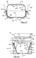
- Fig. 16 there is shown a further arrangement for deforming the container 50 for obtaining discharge of product therefrom, the same container 50 being shown as in the previous embodiments (as shown in particular in Fig. 7).
- compressed gas is applied directly to the lid 52 of the container by defining a manifold chamber 107 between the lid 52 and a sealing member 108 located above and in sealing contact with the upper lip 60 of the container 50.
- the sealing member 108 is formed with an annular seal 109 of resilient material which is arranged to be urged into sealing engagement with the rim 60.
- the sealing member 108 is of inverted cup shape and is provided with a duct 110 for admitting and discharging compressed gas into and from the chamber 107.
- the sealing member 108 is carried on a piston rod 111 of a piston and cylinder arrangement 112 having a piston 113 and inlet and outlet ducts 114 communicating with a source of compressed gas including a gas reservoir (not shown).
- the container is located in a discharge position in apparatus similar to that of Fig. 15.
- compressed gas is admitted to the piston and cylinder 112 to move the sealing member 108 downwardly with the seal 109 urged into engagement with the lip 60.
- compressed gas is admitted into the chamber 107 through duct 110 to pressurise the lid 52 of the container.
- the deformable portion 61 of the container is deformed downwards towards the base 51 of the container for discharge of product through the outlet 57 in a similar manner to that previously described so that the portion 61 after completion of a discharge movement lies closely adjacent the inner surface of the base 51.
- the air pressure in the chamber 107 is released and the piston 113 is returned to its upper position releasing the sealing member 108 from engagement with the container.
- the seating 43 is then moveable towards a container release position.
- sealing member shown in Fig. 16 other sealing means may be employed, for example a sealing arrangement in which opposed sealing members move towards one another to grip the rim of the container 50 between them prior to pressuring the space above the lid 52 of the container. Again piston and cylinder means may be employed for obtaining relative movement between the sealing members.
- the diameter of the piston and cylinder 112 is relatively large and the stroke of the piston 113 is relatively short to ensure that the force being applied to the container by the seal 109 exceeds the back pressure through entry of air into the chamber 107 and an adequate seal is maintained with the container.
- the use of the pressurised chamber 107 ensures that pressure is applied equally to the lid 52 both vertically and laterally and the lid 52 remains adequately secured to the base 51.
- the duration and pressure of air supplied to the chamber 107 is adjustable and in accordance with the product requirements.
- the sealing member 108 may be removably associated with the rod 111 for ready replacement and/or cleaning.
- FIG. 17 there is shown an alternative form of container 50 for use with any of the embodiments of the apparatus of the invention.
- container 50 for use with any of the embodiments of the apparatus of the invention.
- the same reference numbers are used for similar parts to those in previous embodiments.
- the base 51 of the container 50 is formed of relatively rigid material and in use is located in a suitably shaped seating member 43.
- the base 51 has an outlet 57 which can be in any of the forms previously described but is preferably formed centrally of the base using the arrangement of Fig. 13 having lines of weakness radiating from a central point.
- the outlet 57 is conveniently covered before a discharge operation by a sealing strip (not shown) which may be peeled off or which opens up when discharge takes place.
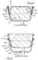
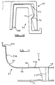
- the base 51 is of generally circular cross section which is flat over its lower surface 55, has tapered side walls 53 merging with the base 55 through radiused portions 56. At the upper edge of the side wall 53 is formed an out-turned lip 53' arranged to sealingly engage with a corresponding lip 54 of the lid 52.
- the lid 52 is of different form to the previous container embodiments and comprises an inverted cup-shaped deformable portion 61, 62 and 63 which mirrors the shape of the base 51, the portion 63 being generally cylindrical but tapered inwardly towards its upper end.
- the top surface is generally flat and merges with the wall 63 through a radiused portion 62.
- the lid may have a concave depression, as at 61A, prior to assembly with the base, the depression being able to take up a convex shape, as at 61B after filling and assembly.
- the lip 54 is formed at the lower end of the side wall 63 to engage over the lip 53' of the base 51.
- the lips 53 and 54 may be connected to one another in a different manner, such as by heat sealing to ensure that, once assembled, the container parts 51 and 52 are sealingly secured together.
- Filling and discharge of the container of Fig. 17 may be achieved in the manner described in relation to the previous embodiments.
- filling of the container is achieved before assembly of the lid 52 with the base 51 in the manner previously described for the other embodiments of container, product being placed into the base 51 above the upper level of the base in order that the container, when assembled, is substantially filled.
- product may be introduced into the container 50 when the container parts 51 and 52 are assembled by introduction through the opening 57.
- the opening 57 may be formed in the manner of the other containers described but preferably with the arrangement of Fig. 13, with or without a sealing strip.
- the outlet may be formed in the lid 52.
- Discharge of the filled container may be by use of the plunger arrangements shown and described in relation to Figs. 1-5, or Fig. 6.
- discharge may be by the arrangements shown and described in Fig. 14 or Fig. 16.
- the container of Fig. 17 provides a simplified form of container compared with that of the previous embodiments. If required the seating 43 can have upward extensions 43', shown in Fig. 17, according to the arrangement used for deforming the container.
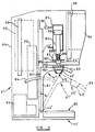
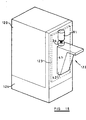
- Fig. 18 there is shown dispensing apparatus incorporating a housing 120 which is arranged to be refrigerated and insulated and to store containers of product for use in the dispensing apparatus shown generally at 122.
- the apparatus for discharging the containers of product may be of any of the forms previously described but the illustrated arrangement 122 is based on the apparatus of Fig. 6 having an arm 41 and operating plunger 36.
- the dispensing apparatus is mounted on the front of the housing 120 on a panel 123 which is conveniently in the form of a door mounted on vertical pivots (not shown) at one side of the door to gain access into the interior of the housing 120.
- a compartment 124 in which is contained an air compressor arid reservoir (not shown) or a compressed gas cylinder for powering the dispensing apparatus.
- the housing 120 may be formed with a series of shelves for locating the containers 50 at the desired temperature. Access to the containers may be through the door 123 but, since opening the door 123 will cause the refrigerated compartment formed by the housing 120 to warm up, other arrangement can be made for gaining access to the containers 50. For example a series of drawers of insulating or non-insulating material may be located within the housing 120, the housing itself also being insulated. Thus opening the door 122 to gain access to a drawer does not result in the containers in the other drawers being warmed.
- the compartment 124 may also house refrigeration equipment for the housing 120 and the refrigeration equipment may include a forced air fan for circulating cold air around the housing 120.
- a "cold wall” evaporation system may also be incorporated to avoid the need for regular defrosting. Defrosting can then be part of regular weekly maintenance.
- the housing 120 can be used for tempering or warming up the containers 50 introduced at low temperature to the preferred dispensing temperature of the product.
- the housing may include a heat sink for providing a thermal storage of "cold" to give more rapid cooling for the heat sink when required.
- a fan may be provided to direct air for cooling over the heat sink.
- the housing 120 may be arranged so that the containers descend by gravity from the upper part of the housing towards the lower part as containers are used, there being an entry into the housing 120 at the lower region thereof for removing the containers, such entry being a flap, drawer or similar arrangement.
- the housing arrangement described may be provided independently of the dispensing apparatus.
- housing 120 may be arranged with the compartment 124 at the top of the housing, and coin-freed dispensing of containers 50 from the housing may also be provided.
- other drive means may be used, for example containers of compressed gas (Fig. 6, 14 and 16), or by mechanically operated drive piston (Fig.6)
- the containers described are conveniently sized and the dispensing apparatus arranged to enable a single portion of product to be contained and dispensed from each container.
- Differently sized containers may be provided for serving different sized portions and the same apparatus may be used for differently sized containers by, for example, providing deforming means both in the plunger described which operate covers a variable stroke according to the size of the container thus the containers may be of different lengths.
- deforming means both in the plunger described which operate covers a variable stroke according to the size of the container thus the containers may be of different lengths.
- the arm 41, of the apparatus of Figs. 1-5 and Fig. 6 is movable manually but the arm 41 may be powered in pivoting between the operating or dispensing position and the non-operating or location position.
- there may be a proximity switch which detects the location of a container in the seating 43 to initiate movement of the arm followed by a dispensing action when the container and arm reach the dispensing position.
- the placing of a container in the seating is followed by manual action of a dispensing operation including an arm movement followed by a dispensing movement.
- each embodiment of container the base and the lid are each nestable with other bases and lids respectively.
- Such nestability requires that nesting and denesting be achievable simply, by mechanical means, so that containers can be filled and assembled automatically by such machines.
- shoulders, lugs or other means whereby the lids and bases do not become locked together.
- a concave depression may be formed centrally of the domed portion of the lid as shown in Fig.17.
Abstract
Description
- This invention relates to dispensing apparatus for dispensing a viscous or semi-solid product from a container.
- In dispensing food products hygiene requirements are becoming even stricter. Moreover convenience and variety of product are of greater importance.
- An object of the invention is to provide dispensing apparatus especially suitable for food products which is simple, adaptable and hygienic.
- According to the invention there is provided, according to one aspect, dispensing apparatus for dispensing a viscous or semi-solid product from a container comprising a base, a deformable portion and an outlet, the apparatus comprising deforming means movable to engage and deform the deformable portion to discharge product from the container through the outlet, a seating for supporting the base of the container during dispensing of product from the container, an arm carrying the seating and movable between an operating position and a non-operating position in which the container may be removed from and placed in the seating, and support means for the arm whereby the arm is movable between said positions, the deforming means being engageable with the container only in the operating position.
- Preferably the deforming means is a plunger movable in a generally vertical direction, and the seating, in the operating position, is located vertically below the plunger, the arm and the seating being movable about a generally horizontal axis of the support means to a non-operating position to one side of the operating position.
- Conveniently the seating and the arm are presented generally horizontally in the operating position and downwardly inclined to the horizontal in the non-operating position.
- Preferably the seating and the arm are releasably securable in each of the operating and non-operating positions and the plunger is movable only when the seating is in the operating position.
- The arm may be L-shaped and located in an inverted position, the shorter limb of the arm carrying the seating, and pivot means is located towards the lower end of the longer limb of the arm.
- The arm may have a handle whereby the arm is movable manually between the operating and non-operating positions, and the seating is arranged for the container to be lifted up and out of the seating, the deformable portion of the container being presented upwardly towards the plunger and the outlet being presented downwardly from the arm when the container is located in the seating.
- The apparatus may include an upright frame having towards its upper end a support for the deforming means and its associated drive means, the frame having intermediate its ends the arm and associated seating, and the frame having towards its lower end a base for supporting the frame, the base including a receiver spaced below the seating and giving access to a receptacle for product discharged from the container.
- Conveniently the frame houses drive means for the deforming means and lighting means, and a housing surrounds the lighting means and has a light transmission region for lighting the housing from within.
- The deforming means may be driven by a compressed gas operated piston and cylinder arrangement, and the apparatus includes a source of compressed gas and gas reservoir for supplying pressurised gas to the piston and cylinder.
- Preferably the deforming means includes locating means movable to engage with the container to locate the container in the seating, and pressure generating means which engages with the deformable portion of the container to deform the portion towards the base in discharging product through the container outlet and the locating means and the pressure generating means are relatively movable so that, after the locating means has engaged the container, the pressure generating means moves relative to the locating means to discharge said product.
- The locating means may comprise a locating member slidably mounted relative to the pressure generating means and resiliently urged by spring means towards a locating position, whereby after said member locates with the container the pressure generating means moves against the action of the spring means to deform the deformable portion of the container and the pressure generating means comprises a plunger head which is shaped to correspond with the internal shape of the base of the container. Alternatively the locating member may be powered towards a locating position independently of operation of the pressure generating means.
- Conveniently the plunger head is generally cylindrical with curvilinear surfaces at its region which engages the deformable portion of the container.
- In one arrangement the seating is a cup-shaped member arranged to receive a correspondingly-shaped base of the container, the seating having a central opening through which the container outlet is directed when the container is placed in the seating, the container being liftable out of the seating after a dispensing action, and the seating being removable from the arm. The seating member may be secured permanently on the arm.
- According to another aspect of the invention dispensing apparatus for dispensing a viscous or semi-solid product from a container comprising a base, a deformable portion and an outlet, the apparatus comprising deforming means arranged to deform the container to discharge product from the container through the outlet, the deforming means including locating means movable to engage with the container to locate the container, and a plunger which engages with the deformable portion of the container to deform the portion towards the base in discharging product through said outlet, the locating means and the plunger being relatively movable so that, after the locating means has engaged the container, the plunger moves relative to the locating means to discharge said product.
- According to a further aspect the invention provides dispensing apparatus for dispensing a viscous or semi-solid product from a container having a base, a deformable portion and an outlet, the apparatus comprising deforming means arranged to deform the deformable portion to discharge product from the container through the outlet, drive means for the deforming means, a seating for supporting the container, a frame on which the deforming means, the drive means and the seating are supported, the frame also housing a reservoir for compressed gas providing a source of compressed gas for operating the drive means.
- The invention also provides a container for use with the dispensing apparatus comprising a base for receiving product to be dispensed, an outlet opening for discharge of product, a closure member or lid for closing the base after admitting product to the base, a deformable region of the closure member arranged to deform upon engagement by deforming means and to be moved towards the base to discharge product from the outlet, the closure member and the base each being nestable with other closure members and bases respectively when separate from one another, the base having upper and lower regions arranged so that when assembled the deformable region of the closure member extends into the upper region of the base and, upon deformation of the deformable region, the deformable region enters and moves to adjacent the internal surfaces of the lower region of the base, the base being of relatively rigid material compared with the deformable region.
- Conveniently at the junction between the upper and lower regions of the base there is formed a shoulder, and the closure member extends towards its outer part to adjacent the shoulder, the closure member having inwardly of the outer part a domed region which, in use, is engaged and deformed by the deforming member towards the lower region of the base.
- The outer region of the top part may include a turned over lip whereby the top portion is secured to the base part by the turned over lip engaging with the upper edge of the base part when the top part and the base part are assembled together after the base part is filled with product. Alternatively there are provided inter-engaging lugs or profiles on cooperating side walls of the lid part and the base part, or the outer edges of the lid and base are heat sealed together.
- The container parts are conveniently formed of plastics by injection moulding, by thermoforming or by blow moulding or they may be of paper or cardboard which may be coated with plastic.
- The dispensing apparatus may have a manually or power-operated drive means which causes the deforming means in the form of a plunger to be reciprocally movable towards and away from a container in a dispensing operation of the apparatus. The drive means may be electrically, hydraulically or gas operated.
- Conveniently the arm is pivotable between a product discharge position and a container location position by pivoting through about 40-60° from a horizontal discharge position so that the support is presented to a better viewing position to the operative.
- When the plunger is manually operated there may be provided a manually movable lever to which a shaft is attached for rotation therewith, and a linkage carried on the shaft is connected to a rod on one end of which is mounted the plunger.
- Conveniently the plunger is movable along and guided by a cylinder arranged vertically and above a container locating position.
- There may be provided a storage compartment for containers with, if required, refrigeration means for maintaining the containers at the desired dispensing temperature.
- Conveniently the central deformable region is connected to the outer region through an integral flexible folded portion. The folded portion may have downwardly and upwardly directed folds one of which lies closely adjacent an inner surface of the base part when assembled therewith and the junction between the downward and upward folds preferably lying half way down the base part when assembled.
- Preferably the central region includes a generally planar portion and the base part is of generally circular section.
- Further features of the invention will appear from the following description of embodiments of the invention given by way of example only and with reference to the drawings, in which:-
- Fig. 1 is a side elevation of one embodiment of dispensing apparatus,
- Fig. 2 is a view in the direction of
arrow 2 in Fig. 1, - Fig. 3 is a vertical section through a plunger assembly portion of the apparatus of Figs. 1 and 2,
- Fig. 3A is an alternative form of the assembly of Fig.3,
- Fig. 4 is a section corresponding to that of Fig. 3 showing the plunger in an intermediate position,
- Fig. 5 is a view corresponding to Fig. 3 showing the plunger in a lowermost position,
- Fig. 6 is a side elevation of a second embodiment of the invention,
- Fig. 7 is a section through an assembled container for use with the apparatus of Figs. 1-5, and Fig. 6,
- Fig. 8 is a part section through a base part of the container of Fig. 7 nested with another base part,
- Fig.8A is a perspective view of the container of Fig. 7,
- Fig.8B is a view corresponding to Fig 8A showing the outlet opened,
- Fig. 9 is a part section through a top part or lid of the container of Fig. 7 nested with another top part,
- Fig. 9A is a perspective view of the top part of Fig. 9,
- Fig. 10 is a part section of the container of Fig. 7,
- Fig. 11 is a part section of the base part of the container,
- Fig. 12 is a plan view showing the opening in the base part of
the container in the direction of
arrow 11 in Fig. 11, - Fig.13 is in perspective view from below showing an alternative form of outlet opening,
- Fig.14 is a sectional view showing an alternative form of deforming means for the container,
- Fig.15 is a side elevation of dispensing apparatus incorporating the deforming means of Fig. 14,
- Fig.16 is a cross-section through a further form of deforming means for the container,
- Fig.17 is a cross-section through an alternative form of container, and
- Fig. 18 is a perspective view of dispensing apparatus incorporated with a housing for storing filled containers for use with the apparatus
-
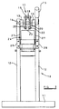
- Referring to the drawings and firstly to Figs. 1-5, dispensing apparatus for a dispensing system is manually operated and includes a vertically arranged
frame 10 having abase 11 on which may be supported a receptacle (not shown) for product. Theframe 10 includes upwardly extendingframe members 12 at the uppermost end of which are mountedhorizontal support arms 13. Between thearms 13 is rotatably mounted ashaft 14 on one end of which is carried for rotation therewith alever 15. Thelever 15 is movable between an upper inoperative position 15' through an intermediate position 15'' and a lower position 15'''. - Mounted centrally of the
shaft 14 is alinkage assembly 17 including a pair oflinks 18 rotatably carried on theshaft 14. At the opposite ends of thelinks 18 is carried aspindle 19, thelinks 18 being pivotable relative to thespindle 19, and a further pair oflinks 20 depend from and are pivotally mounted on thespindle 19. As an alternative to the linkage shown other arrangements can be used such as a double cantilever arrangement, so that downward pressure on theplunger 36 is always in the vertical direction. - The
further links 20 are interconnected at their lower ends by aspindle 22 which extends through the upper end of arod 23 which is the operating rod of a plunger assembly 24 (shown in more detail in Fig. 3). Thespindle 22 is rotatably mounted in abore 25 in therod 23. - The
plunger assembly 24 includes acylinder 26 which is mounted on theframe 10 by vertically arrangedplates 27 attached at their upper ends to thebeam 13 and towards their lower ends tobrackets 28 secured to the uprights 12. Thebrackets 28 andplates 27 are interconnected and together provide a support for thecylinder 26. - The
cylinder 26 is open ended and receives coaxially therod 23. Therod 23 carries fixed thereto an upperannular member 29 which fits within and for movement along the inner walls of thecylinder 26. Spaced downwardly from theannular member 29 and along therod 23, and axially movable relative to therod 23, is a generally cup-shapedmember 30 comprising a furtherannular member 31 secured to a locatingmember 32 extending downwardly from themember 31 and defining an inner cylindrical bore 33. Towards the lower end of themember 32 is an annular tapered locatingportion 34 which is spaced from the inner walls of thecylinder 26. - Carried at the lower end of the
rod 23 is an engagement member orplunger head 36 secured for movement with therod 23 along thecylinder 33. The lower end of theplunger 36 is formed with aflat surface 37 bounded by acurved periphery 38. - Engaging between the
annular member 29 and themember 31 is a spring 40 which urges themember 31 in a direction away from theannular member 29 but is compressible to the position shown in Figs. 4 and 5 so that theannular member 29 can move close to themember 31 during a dispensing operation. - The
frame 10 also carries intermediate its ends apivotable arm 41 which is located for pivoting on theuprights 12 about horizontal pivots 42. Thearm 41 can pivot downwardly from the horizontal position shown in Fig. 1 to a downwardly. inclined position 41' which is at an angle of some 50° to the horizontal position. - Towards the outer end of the
arm 41 is located a support or seatingmember 43 for receiving acontainer 50 of product to be dispensed. Theseating 43 defines a cup-shaped inner surface 44 in whichcontainers 50, such as shown in Figs. 7-13, can be received. At the lower end of the cup surface 44 is formed a central outlet opening 45 through which product is to be discharged fromcontainers 50. - The
arm 41 is retained in its upper horizontal position by a securingelement 47 which engages over the end of the arm and over thebrackets 28 but it will be appreciated that other securing means whereby thearm 41 may be released from a securing position, may be employed. Upon release of the securingelement 47 the arm is movable downwards aboutpivots 42 to the inclined position 41' which is the position in which containers are placed in and lifted out of the receivingmember 43. - Referring now to Fig.6 a pneumatically operated dispensing machine is shown which utilises the
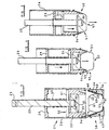
same containers 50 as the previously described machine. In the Fig. 6 machine similar reference numbers are given to parts equivalent to those of the machine of Figs. 1-5. - The machine of Fig. 6 comprises a base 11' and an upwardly extending frame 10'. On the base 11' there is provided a
tray 80 which is located spaced beneath the container dispensing position and extending upwards from thetray 80 is a main frame member 12' located generally centrally of the machine. - To the lower end of the main frame number 12' is a pivot 42'on which is pivotally supported an inverted L-shaped arm 41' having a longer upwardly directed
limb 81 and a shorter outwardly directedlimb 82. Towards the outer end of thelimb 82 is located ahandle portion 83 by which the arm 41' is moved manually between the upright position shown in full lines in Fig. 6 and the inclined inoperative position, shown by chain lines. In the inoperative position the arm is presented to the user for the removal by lifting out, of empty containers from a seating 43', and for the location offull containers 50 in the seating 43'. Movement between the two positions is, in the illustrated embodiment, by moving the arm 41' using thehandle 83. - The arm 41' carries a pair of
arcuate support members 84 which extend through slots in the frame 12' and locate the arm 41' in the operative and inoperative position by engagement with themachine frame 10 and by the use of catches to hold the arm 41' in the required position. A magnetically or pneumatically operated catch is used when the arm is in the operative position and thesupport members 84 may have stops for location in the inoperative position. There is shown apositive locking pin 85 moved by a pneumatic cylinder between a release and a locking position in which the arm 41' is locked, the pin engaging in a recess in thearm 41 in the locking position. A position detector 85' is also provided to detect when the arm 41' is in the operation position. - The outwardly directed
portion 82 of the arm 41' is provided with a seating 43' in whichcontainers 50 are located, the seating being shaped to receive thecontainers 50 and the seating 43' being removable from theportion 82 for cleaning purposes, if required. Centrally and in the base of the seating is provided an outlet opening 45' for permitting passage of the product in thecontainer 50 from thecontainer outlet 57 through said opening. - Located above and axially aligned with the seating 43' is a plunger 36' forming part of a plunger assembly 24'. The plunger 36' is generally cylindrical having, a lower flat portion merging through curvilinear portions with the body of the plunger, as in the previous embodiment. The plunger 36' is carried on a
rod 86 and slidable along therod 86 is anannular disc 87 which is spring urged by aspring 88 towards the upper end of the plunger 36'. Thus theannular disc 87 is moveable relative to the plunger 36' along therod 86. - The
rod 86 is mounted at its upper end on apiston rod 89 andpiston 90 located within apneumatic cylinder 81. Thus thepiston 90 and therod 89 are moved up and down by the introduction of pressure air into thecylinder 91 to cause the plunger 36' to be moved vertically up and down, such movement being movement for discharge of the product fromcontainers 50. - Supply of air to the
cylinder 91 is from areservoir 92 of pressure air which is supplied from a motor andcompressor 93 carried on the machine. Control valves (not shown) control the operation of the piston andcylinder arrangement pin 85 and when there is a container ofproduct 50 located in the seating 43'. Further controls can also be provided for timing the introduction and exhaust of air from thecylinder 91 so that the operator simply initiates the discharge sequence. If required the speed of operation can also be controlled and adjusted manually or automatically by valve means 90' according to the hardness of the product and the ease of extruding the product through the container outlet by control of the air pressure to thecylinder 91. - The sequence of operation of the machine Fig. 6 is to locate a container of
product 50 in the seating 43' when the arm 41' is in the inclined receiving or non-operative position. The arm 41' is then moved to its vertical position in which the seating 43' lies directly below the plunger 36' and the plunger is operative, by manual movement of the arm using thehandle 83. - An operative movement of the plunger 36' is initiated automatically or by a switch so that the plunger moves downwardly towards the
container 50 and theannular disc 87 engages with the top edge of thecontainer 50 and remains in this position during the continued movement of the plunger 36' against the action ofspring 88 to fully discharge the contents of the container through the outlet in the container and through the opening 45' in the seating 43'. During discharge a receptacle (not shown) for receiving product from thecontainer 50 is located below the container discharge outlet. Thedisc 87 may include a downwardly directed shroud (not shown) to prevent access by the operator to the plunger. - Considerable force is exerted during the discharge operation and this is resisted by the arm 41' which is of robust construction. Further details of the discharge operation will appear from the following description since the container operates in a similar fashion for both embodiments of dispensing machine.
- The Fig. 6 embodiment includes a
casing 95 surrounding the components of the machine and there are providedlight boxes light sources - Referring now to Figs. 7-13 the container 50 (shown assembled in Fig. 7) for product is formed of two parts, a base part 51 (Fig. 8) and a top, closure or lid part 52 (Fig. 9) which may each be formed of plastics or cardboard. The
base part 51 has tapered lower and upperside wall portions shoulder 53C which walls taper outwards in the upwards direction terminating at the upper edge in alip 54, the angle of taper being suited to enablebase parts 51 to be nested one within the other as shown in Fig.8. A suitable angle is some 5° to the vertical or an included angle of 10°. - A
base surface 55 of thebase part 51 is generally planar, merging into theside walls 53 through a radiusedportion 56. Centrally of thebase portion 55 is formed an outlet 57 (see particularly Fig. 8A, 8B, 11 and 12) which is formed of weakened radial, star-shapedlines 58 which are capable of being opened up to form an outlet. The outlet may be formed under pressure of product in the container or by being formed of aremovable part 57A (as shown in Fig.12), removal of which breaks through the weakened portions. - In the arrangement shown in Figs. 7-12 the
outlet 57 is provided by defining a star shape by the weakened or thinnedportion 58 of thebase 55. Aremoval element 70 in the form of a disc shaped element is attached to thepart 57A of thebase 55 within thestar 58 to be removed by connectingelements 71 whereby when theelement 70 is grasped and tilted downwards thecentral part 57A of thebase 55 within the star is detached to provide a star-shaped outlet opening 57 in thebase portion 55 through which product is discharged. - The top part 52 (Fig.9) of the
container 50 includes aperipheral lip 60 which is arranged to engage over thelip 54 of thebase part 51 to secure thetop part 52 to thebase part 51 and seal the interior of the container. The interfitting of thelip 60 with thelip 54 is, as shown, by a clip action, but it may be by welding, heat sealing or by the parts being a close fit in one another. - The clip arrangement by which the
top part 52 is secured to thebase part 51 is shown more clearly in Fig. 10. Theperipheral lip 60 on thetop part 52 is formed with a downwardly directedannular channel 75, the outer internal side of which is formed at 76 with a thickened region. - The
lip 54 on thebase part 51 is arranged to fit into thechannel 75 and has a thickenedregion 77 which interfits with the thickenedregion 76 when theparts top part 52 onto thebase part 51. - The
top part 52 has a centraldeformable region 61 which is generally planar in the form of a disc but which merges through aradius 62 with deformable folded overportions lip 60 being formed at the upper edge of the folded overportion 64. At the junction between the downwardly directed folded overportion 63 with the upwardly directed folded overportion 64 there is aportion 65 which, when thetop part 52 is assembled to thebase part 51 is located half way down thebase part 51 and against theshoulder 53C. Theportion 64 is thickened towards its lower end to provide ashoulder 64A for when top parts are nested together and to prevent the parts locking together. Theportion 64 is tapered to match the taper of theside wall 53B of the base part. - At least the
regions top part 52 are formed of flexible material so that the top part can deform during dispensing of product from thecontainer 50 and due to engagement of theplunger 36 with thecentral region 64 of thetop part 52. - In use of the container the
base part 51 is normally stored with a plurality of base parts nested together (Fig. 8).Individual base parts 51 are released from the nested parts and are presented to a product filling machine, which may be of known form, by which thebase part 51 is filled with a predetermined amount of product above the level of theshoulder 65 of thepart 51 as shown in Fig.8 at F. Atop part 52, also normally stored nested together (Fig.9), is denested then fitted to thebase part 51 until the parts are secured together, in which position the folded overportion 64 lies closely adjacent theinner side wall 53B of the base part, as shown in Fig 7. - In the assembled condition the container containing product may be frozen, transported and stored. Prior to dispensing of product from the
container 50 the product may be tempered to a suitable dispensing temperature in the case of ice cream or other frozen confectionery product or, in some cases, the product within the container may be heated by microwave means. - When it is desired to dispense product from the
container 50 using the dispensing apparatus of Figs. 1-5 of the invention a container is located in theseating 43 with thearm 41 in its lowered position 41'. Thearm 41 is then raised to the horizontal dispensing position and held in place by the securingelement 47. At this time thelever 15 is in its raised position. A proximity detector (not shown) may be provided to detect that acontainer 50 is in position in the seating before a discharge operation is started. To dispense product from thecontainer 50 thearm 15 is lowered manually which causes, through thelinkage 17, therod 20 to be moved in a downwards direction from the position shown in Fig. 3 towards the position shown in Fig. 4. - At the Fig. 4 position the
tapered portions 34 have entered the space between the foldedportions top part 52 to thebase part 51 with the container engaged with theseating 43 with thelip 54 over thetop edge 43A of the seating. Only when this securing action has been performed is theplunger 36 engaged with thecentral region 61 of thetop part 52 and themember 32 is prevented from further downward movement. Therod 23 continues to move downwards so that themember 32 slides over the rod compressing the spring 40, thesurface 37 of theplunger member 36 engages theregion 31 and deforms the top part downwardly reducing the internal volume of thecontainer 50 and causing product in the container to be discharged through theoutlet 57 as thecentral region 61 of the top part is deformed towards thebase surface 55 of thebase part 51. During this movement the downwardly directedportion 63 of thetop part 52 unfolds downwards so that it lies adjacent theinner wall 53A of thebase part 51 at 61' (Fig. 7). - Upon completion of the movement of the
plunger part 36 towards thebase 55 of thebase part 51 the plunger has adopted the position shown in Fig. 5 and the container is substantially emptied of product. During discharge of product through theoutlet 57 the product is shaped according to the shape of thedischarge outlet 57 and the product is discharged into a receptacle below theopening 45 the receptacle being sized to match the capacity of the container. Upon completion of the stroke of theplunger part 36, at which thelever 15 is in the position 15''', discharge of the contents of thecontainer 50 is complete. Thelever 15 is returned to its initial position, the securing means 47 is released from thearm 41 and the empty container, still remaining in theseating 43 by engagement of the locating means 32 with thecontainer 50, is removed therefrom. The apparatus is ready for a fresh dispensing operation by location of another container in theseating 43. - In Fig. 3A there is shown an alternative form of locating means 32' in which the tapered lower end is replaced by a generally flat end which in use engages the top outer edge of the assembled container.
- It has been found that this gives adequate support for the container whilst avoiding any tendency for the container to require release from the plunger assembly after a discharge operation.
- A similar apparatus to that described in Figs. 1-5 can be provided in which the plunger movement is power operated by a piston and cylinder arrangement or powered means, such as is shown in Fig. 6.
- In the dispensing of product from the machine of Fig. 6 this operation is similar but it will be noted that the plunger 36' does not incorporate the
portion 34 sincesuch portions 34 are not always found to be necessary. Moreover the top edge of thecontainer 50 is simply engaged by theannular disc 87 in the Fig. 6 machine. - The machine of Fig. 6 is arranged so that this plunger cannot be operated unless the container is in the operating position beneath the plunger. This may be by means of an interlock (not shown) detecting the location of a container in the seating and detecting the position of the arm in the upright position. Further controls may be provided for automatically energising the plunger when the interlocks detect that a dispensing operation can be performed and for returning the plunger to its upper position when the container is fully discharged. The controls can also control the rate of discharge according to the speed of the plunger movement, and whether the stroke of the plunger is interrupted for partial discharge of the container contents. Alternatively container discharge and plunger movement may be manually initiated by suitable switches. The air reservoir of the Fig. 6 embodiment enables repeat discharge of product beyond the rate of supply of the air compressor, for rapid repeat operation of the dispenser. Safety interlocks are also provided for avoiding any danger to the operator from the plunger movement.
- It will be seen that the container is supported in the
seating 43 during discharge of its contents with thetop portion 52 firmly secured to thebase part 51 during discharge and substantially the whole of the contents of the container may be discharged therefrom. The amount of product within the container can be selected according to requirements to be the size of a predetermined portion of product to be received by a receptacle. Alternatively several portions may be discharged from the same container simply by halting the movement of thedischarge plunger 36 in an intermediate position when sufficient product has been discharged. Thus thecontainer 50 may be of any suitable size to suit requirements. - It will be seen that at no time during the discharge operation should product contaminate the apparatus because the top part of the
container 52 remains sealed to thebase part 51 and product from theoutlet 57 is directed directly into a receiving container. Nevertheless theseating 43 and the associated parts of the apparatus may be readily removable for cleaning purposes. - Fig. 13 illustrates an alternative outlet arrangement for the
container 50 which is in many respects the same as the previously described container. In the Fig. 13 arrangements instead of the star shapedportion 57A providing the outlet for discharging product from the container the container is formed with weakenedlines 100 radiating from a central position or thelines 100 can be slits or discontinuous breaks in the base of the container. During discharge from the container pressure of product will cause the triangular portions between thelines 100 to be bent outwardly from the centre and permit the product to discharge from the container. - Since the product within the container will usually be semi-solid and frozen the product should riot be able to escape through the opening prior to a dispensing operation. In addition however the container of Fig. 13 may be located within a sealed bag which may contain information concerning the product. Thus to utilise a container of this kind it would first be necessary to remove the bag from the container before placing it in the
seating 43 but it would not be necessary to make any opening in the base of the container. Alternatively theportion 57A may be covered with a removable seal such as a peel off seal or a seal which in itself is opened up by the pressure of product being discharged. - Instead of the container being of circular section, as illustrated, the container may be of other suitable shapes, for example elliptical, square or rectangular, in the latter forms having radiused corners. The container is preferably formed from plastics by thermoforming.
- It should also be understood that the container may be formed so that the
discharge opening 57 is formed in thepart 52, hitherto called the top part or lid. In this case thecontainer 50 would be located in the dispensing apparatus in the inverted position and theplunger 36 would engage and deform theparts part 51 into theparts part 52 to discharge product from theopening 57 in thepart 52, theopening 57 being formed in the manner described in relation to he illustrated container. Similarly the modified container would be located and retained in a seating as previously described. - Instead of the interfitting arrangement of top and base parts described other arrangements may be used. For example the
side wall 53B of thepart 51 and theside wall 64 of thepart 52 may have cooperatively shaped profiles so that one is located in the other to secure the parts together, as by contoured indentations or lugs - As an alternative to the
seating 43 shown the seating surface may terminate short of theportion 56 of thepart 51 to further reduce any chance of product being deposited on theseating 43. - Although the dispensing apparatus and, in particular, the plunger assembly, is, as described, arranged to have a location movement followed by a discharge movement, the use of a movable support for the container which is lifted up into position towards the plunger assembly may enable the location movement of the plunger assembly to be omitted or modified. Location of the container relative to the plunger assembly may be wholly or, in part, achieved when the container is located relative to the plunger assembly. However it is normally necessary to have relative movement and apply force between the plunger assembly and the container support in order to firmly locate the container during dispensing.
- Moreover the apparatus provides simple and cost effective means for hygienically dispensing the product into any suitable receptacle such as a dish, bowl or an edible receptacle, for example a cone. A wide variety of product can be dispensed by the apparatus depending only on which product is filled into the containers.
- Due to the arrangement of the apparatus the user can readily locate containers of product on the apparatus because the
seating 43 is presented towards the user to readily locate containers in and out of the seating. This is achieved without having to have an unduly long stroke of therod 20 to afford room for location of containers below the operating plunger. - Referring now to Figs. 14 and 15 there is shown the container previously described (see in particular Fig.7) utilised with an alternative form of means for deforming the container to obtain discharge of product therefrom. In this arrangement the same reference numbers are used for similar parts to those in previous embodiments.
- When the
container 50 is located in a dispensing or discharge position there is located above the container 50 a compressedair manifold member 101 defining achamber 102 communicated with a source of compressed gas through aduct 103. Aflexible membrane 104 defines the lower side of thechamber 102, the membrane being formed of resilient, flexible material which has a high degree of extensibility. Themembrane 104 is conveniently formed with radial convolutions to obtain additional extension from the retracted position, the convolutions returning to their initial position after extension. - At the lower side of the
manifold member 101 is anannular plate 105 which is engagable with the upper outer rim orlip 60 of thecontainer 50. To deform thecontainer 50 and discharge the contents thereof compressed gas is admitted throughduct 103 into thechamber 102 whereby to deform themembrane 104 downwards into contact with thelid 52 of the container. Theportion 61 of the lid is deformed downwards discharging product through theoutlet 57 until theportion 61 is deformed into contact with or closely adjacent the inner surface of the base 51 whereupon the container is substantially empty. - Upon emptying of the container gas is exhausted from the
chamber 102 and themembrane 104 resumes its initial position. Themembrane 104 may be provided with a spring return arrangement (not shown) between themembrane 104 and thehousing 101. - As a safety feature there is provided an interlock (not shown) to ensure that gas cannot be admitted to the
chamber 102 unless there is afull container 50 in the discharge position in theseating 43. The pressure and rate of flow of gas into thechamber 102 is controlled and adjustable according to the rate of discharge of product required, the nature of the product and the size of the container. At a predetermined pressure gas may be admitted for a predetermined period of time which is adjustable. A suitable material for themembrane 104 is polyurethane or other material which can resume its initial position without permanent distortion. - The
manifold member 101 can be replaceably mounted on the apparatus to ensure that adequate sealing is retained and for the possibility of cleaning although such manifold would not normally come into contact with the product. - In Fig.15 is shown one way in which the manifold 101 can be mounted in dispensing apparatus, the apparatus being in other respects similar to that shown in Fig.6. The
manifold member 101 is mounted on arigid arm 105 on theframe 12 of the apparatus. If desired themanifold member 101 may be vertically moveable into engagement with thecontainer rim 60 after location of thecontainer 50 in the dispensing position. - It will be seen that with the arrangement of Fig.14 the use of a pressurised
membrane 104 ensures that pressure is applied to thelid 52 of thecontainer 50 laterally as well as vertically helping to ensure that thelid 52 remains firmly connected to thebase 51 and also allowing for the discharge of product which may contain pieces such as fruit and nuts within the product. The arrangement takes up little space and is simple in construction. - Referring now to Fig. 16 there is shown a further arrangement for deforming the
container 50 for obtaining discharge of product therefrom, thesame container 50 being shown as in the previous embodiments (as shown in particular in Fig. 7). In this arrangement compressed gas is applied directly to thelid 52 of the container by defining amanifold chamber 107 between thelid 52 and a sealingmember 108 located above and in sealing contact with theupper lip 60 of thecontainer 50. - The sealing
member 108 is formed with anannular seal 109 of resilient material which is arranged to be urged into sealing engagement with therim 60. The sealingmember 108 is of inverted cup shape and is provided with aduct 110 for admitting and discharging compressed gas into and from thechamber 107. - The sealing
member 108 is carried on apiston rod 111 of a piston andcylinder arrangement 112 having apiston 113 and inlet andoutlet ducts 114 communicating with a source of compressed gas including a gas reservoir (not shown). - To obtain discharge of the
container 50 the container is located in a discharge position in apparatus similar to that of Fig. 15. When it is detected that afull container 50 is located in such position onseating 43 compressed gas is admitted to the piston andcylinder 112 to move the sealingmember 108 downwardly with theseal 109 urged into engagement with thelip 60. When a full seal is achieved compressed gas is admitted into thechamber 107 throughduct 110 to pressurise thelid 52 of the container. Thedeformable portion 61 of the container is deformed downwards towards thebase 51 of the container for discharge of product through theoutlet 57 in a similar manner to that previously described so that theportion 61 after completion of a discharge movement lies closely adjacent the inner surface of thebase 51. - After discharging the product from the container the air pressure in the
chamber 107 is released and thepiston 113 is returned to its upper position releasing the sealingmember 108 from engagement with the container. Theseating 43 is then moveable towards a container release position. - Instead of the sealing member shown in Fig. 16 other sealing means may be employed, for example a sealing arrangement in which opposed sealing members move towards one another to grip the rim of the
container 50 between them prior to pressuring the space above thelid 52 of the container. Again piston and cylinder means may be employed for obtaining relative movement between the sealing members. - The diameter of the piston and
cylinder 112 is relatively large and the stroke of thepiston 113 is relatively short to ensure that the force being applied to the container by theseal 109 exceeds the back pressure through entry of air into thechamber 107 and an adequate seal is maintained with the container. - As with the previous embodiment the use of the pressurised
chamber 107 ensures that pressure is applied equally to thelid 52 both vertically and laterally and thelid 52 remains adequately secured to thebase 51. As before the duration and pressure of air supplied to thechamber 107 is adjustable and in accordance with the product requirements. The sealingmember 108 may be removably associated with therod 111 for ready replacement and/or cleaning. - Referring now to Fig. 17 there is shown an alternative form of
container 50 for use with any of the embodiments of the apparatus of the invention. In this container the same reference numbers are used for similar parts to those in previous embodiments. - The
base 51 of thecontainer 50 is formed of relatively rigid material and in use is located in a suitably shaped seatingmember 43. Thebase 51 has anoutlet 57 which can be in any of the forms previously described but is preferably formed centrally of the base using the arrangement of Fig. 13 having lines of weakness radiating from a central point. Theoutlet 57 is conveniently covered before a discharge operation by a sealing strip (not shown) which may be peeled off or which opens up when discharge takes place. - The
base 51 is of generally circular cross section which is flat over itslower surface 55, has taperedside walls 53 merging with the base 55 through radiusedportions 56. At the upper edge of theside wall 53 is formed an out-turned lip 53' arranged to sealingly engage with acorresponding lip 54 of thelid 52. - The
lid 52 is of different form to the previous container embodiments and comprises an inverted cup-shapeddeformable portion base 51, theportion 63 being generally cylindrical but tapered inwardly towards its upper end. The top surface is generally flat and merges with thewall 63 through a radiusedportion 62. However the lid may have a concave depression, as at 61A, prior to assembly with the base, the depression being able to take up a convex shape, as at 61B after filling and assembly. Thelip 54 is formed at the lower end of theside wall 63 to engage over the lip 53' of thebase 51. Alternatively thelips container parts - During discharge of the container of Fig. 17 the
portions portion 61 becomes closely adjacent the inner wall of the base 51 at which time the contents of the container are substantially discharged through theoutlet 57. - Filling and discharge of the container of Fig. 17 may be achieved in the manner described in relation to the previous embodiments. Thus filling of the container is achieved before assembly of the
lid 52 with the base 51 in the manner previously described for the other embodiments of container, product being placed into thebase 51 above the upper level of the base in order that the container, when assembled, is substantially filled. Alternatively product may be introduced into thecontainer 50 when thecontainer parts opening 57. Theopening 57 may be formed in the manner of the other containers described but preferably with the arrangement of Fig. 13, with or without a sealing strip. The outlet may be formed in thelid 52. - Discharge of the filled container may be by use of the plunger arrangements shown and described in relation to Figs. 1-5, or Fig. 6. Alternatively discharge may be by the arrangements shown and described in Fig. 14 or Fig. 16. The container of Fig. 17 provides a simplified form of container compared with that of the previous embodiments. If required the
seating 43 can have upward extensions 43', shown in Fig. 17, according to the arrangement used for deforming the container. - Referring now to Fig. 18 there is shown dispensing apparatus incorporating a
housing 120 which is arranged to be refrigerated and insulated and to store containers of product for use in the dispensing apparatus shown generally at 122. The apparatus for discharging the containers of product may be of any of the forms previously described but the illustratedarrangement 122 is based on the apparatus of Fig. 6 having anarm 41 and operatingplunger 36. The dispensing apparatus is mounted on the front of thehousing 120 on apanel 123 which is conveniently in the form of a door mounted on vertical pivots (not shown) at one side of the door to gain access into the interior of thehousing 120. In the base of the housing is located acompartment 124 in which is contained an air compressor arid reservoir (not shown) or a compressed gas cylinder for powering the dispensing apparatus. Thehousing 120 may be formed with a series of shelves for locating thecontainers 50 at the desired temperature. Access to the containers may be through thedoor 123 but, since opening thedoor 123 will cause the refrigerated compartment formed by thehousing 120 to warm up, other arrangement can be made for gaining access to thecontainers 50. For example a series of drawers of insulating or non-insulating material may be located within thehousing 120, the housing itself also being insulated. Thus opening thedoor 122 to gain access to a drawer does not result in the containers in the other drawers being warmed. - As a further possibility there may be located in the
housing 120 behind thedoor 123 heat retaining flaps suspended from the upper end of the door opening through which access can be gained to the containers, similar to known "push through" selection systems used in refrigerated cabinets. - The
compartment 124 may also house refrigeration equipment for thehousing 120 and the refrigeration equipment may include a forced air fan for circulating cold air around thehousing 120. A "cold wall" evaporation system may also be incorporated to avoid the need for regular defrosting. Defrosting can then be part of regular weekly maintenance. Thehousing 120 can be used for tempering or warming up thecontainers 50 introduced at low temperature to the preferred dispensing temperature of the product. The housing may include a heat sink for providing a thermal storage of "cold" to give more rapid cooling for the heat sink when required. A fan may be provided to direct air for cooling over the heat sink. - As a further alternative the
housing 120 may be arranged so that the containers descend by gravity from the upper part of the housing towards the lower part as containers are used, there being an entry into thehousing 120 at the lower region thereof for removing the containers, such entry being a flap, drawer or similar arrangement. - As a further alternative the housing arrangement described may be provided independently of the dispensing apparatus.
- Moreover the
housing 120 may be arranged with thecompartment 124 at the top of the housing, and coin-freed dispensing ofcontainers 50 from the housing may also be provided. For each of the embodiments of dispensing apparatus described other drive means may be used, for example containers of compressed gas (Fig. 6, 14 and 16), or by mechanically operated drive piston (Fig.6) - The containers described are conveniently sized and the dispensing apparatus arranged to enable a single portion of product to be contained and dispensed from each container. Differently sized containers may be provided for serving different sized portions and the same apparatus may be used for differently sized containers by, for example, providing deforming means both in the plunger described which operate covers a variable stroke according to the size of the container thus the containers may be of different lengths. Although there is described and shown containers in which the outlet from the container is in the base it will be appreciated that the outlet may be formed in the lid or closure member.
- The
arm 41, of the apparatus of Figs. 1-5 and Fig. 6 is movable manually but thearm 41 may be powered in pivoting between the operating or dispensing position and the non-operating or location position. In this arrangement there may be a proximity switch which detects the location of a container in theseating 43 to initiate movement of the arm followed by a dispensing action when the container and arm reach the dispensing position. Alternatively the placing of a container in the seating is followed by manual action of a dispensing operation including an arm movement followed by a dispensing movement. - It has been described that in each embodiment of container the base and the lid are each nestable with other bases and lids respectively. Such nestability requires that nesting and denesting be achievable simply, by mechanical means, so that containers can be filled and assembled automatically by such machines. Thus there should be provided in each case shoulders, lugs or other means whereby the lids and bases do not become locked together.
- In assembling the base and lid it is desirable to apply pressure to the deformable portion of the lid prior to uniting the lid and base at the edge thereof. This maintains the shape of the container and generates a small air pressure in any air in the lid. Alternatively or in addition a concave depression may be formed centrally of the domed portion of the lid as shown in Fig.17.
Claims (13)
- Food dispensing apparatus comprising a refrigerated housing defining storage means for containers of food to be dispensed, door means on said housing and giving access to the interior of the housing, and food product dispensing means mounted on and located externally of the housing, and the dispensing means being arranged to dispense food from containers by extrusion after removal from said housing and location on said dispensing means.
- Apparatus according to claim 1 wherein the dispensing means is mounted on the door means which is openable about a vertical axis.
- Food dispensing apparatus according to claim 1 wherein the housing includes a further releasable opening into the housing which is arranged to provide separate access to containers of food without opening the door means.
- Food dispensing apparatus wherein the releasable opening is in the form of a flap, drawer, or the like located toward the lower region of the housing.
- Food dispensing apparatus according to claim 2, 3 or 4 wherein containers within the housing are arranged to descend under gravity towards the releasable opening.
- Food dispensing apparatus according to any one of the preceding claims wherein the housing incorporates means for heating up or tempering food product in the containers therein, whilst maintaining the food product in a frozen condition.
- Food dispensing apparatus according to any one of the preceding claims wherein the door means is mounted about vertical hinges.
- Food dispensing apparatus according to any one of the preceding claim wherein the dispensing means comprises deforming means arranged to engage and deform containers of food product located thereon and to extrude food product from such containers through a lower container outlet.
- A method of dispensing food from containers wherein containers of frozen food product are introduced into a refrigerated housing through a door on said housing, the food product is heated or tempered in said housing to a dispensing temperature, the container is removed from said housing and placed on food dispensing means mounted on and located externally of the housing, the dispensing means is operated to discharge food product from the container by extrusion through an outlet in the container.
- A method according to claim 9 wherein containers are introduced into the housing through the door which is on the front of the housing and are removed for dispensing through a further releasable opening before placing on the dispensing means.
- A method according to claim 9 or 10 wherein the food dispensing means is mounted on the door which door gives access to the interior of the housing for storage of containers in the housing.
- A method according to any of claims 9 to 11 wherein the containers descend under gravity from a storage position towards a removal position towards the lower region of the housing.
- A method according to any one of claims 9 to 12 wherein food product is discharged from the container by pressurising product in the container and extension through the outlet in the lower part of the container.
Priority Applications (1)
| Application Number | Priority Date | Filing Date | Title |
|---|---|---|---|
| EP06014976A EP1710205A3 (en) | 1994-07-02 | 1995-07-03 | Food dispensing apparatus |
Applications Claiming Priority (5)
| Application Number | Priority Date | Filing Date | Title |
|---|---|---|---|
| GB9413376A GB9413376D0 (en) | 1994-07-02 | 1994-07-02 | Dispensing system |
| GB9413376 | 1994-07-02 | ||
| GBGB9507242.7A GB9507242D0 (en) | 1995-04-07 | 1995-04-07 | Dispensing system |
| GB9507242 | 1995-04-07 | ||
| EP95928386A EP0768982B1 (en) | 1994-07-02 | 1995-07-03 | Dispensing apparatus |
Related Parent Applications (1)
| Application Number | Title | Priority Date | Filing Date |
|---|---|---|---|
| EP95928386A Division EP0768982B1 (en) | 1994-07-02 | 1995-07-03 | Dispensing apparatus |
Related Child Applications (1)
| Application Number | Title | Priority Date | Filing Date |
|---|---|---|---|
| EP06014976A Division EP1710205A3 (en) | 1994-07-02 | 1995-07-03 | Food dispensing apparatus |
Publications (1)
| Publication Number | Publication Date |
|---|---|
| EP1095901A1 true EP1095901A1 (en) | 2001-05-02 |
Family
ID=26305189
Family Applications (3)
| Application Number | Title | Priority Date | Filing Date |
|---|---|---|---|
| EP06014976A Withdrawn EP1710205A3 (en) | 1994-07-02 | 1995-07-03 | Food dispensing apparatus |
| EP00124876A Withdrawn EP1095901A1 (en) | 1994-07-02 | 1995-07-03 | Food dispensing apparatus |
| EP95928386A Expired - Lifetime EP0768982B1 (en) | 1994-07-02 | 1995-07-03 | Dispensing apparatus |
Family Applications Before (1)
| Application Number | Title | Priority Date | Filing Date |
|---|---|---|---|
| EP06014976A Withdrawn EP1710205A3 (en) | 1994-07-02 | 1995-07-03 | Food dispensing apparatus |
Family Applications After (1)
| Application Number | Title | Priority Date | Filing Date |
|---|---|---|---|
| EP95928386A Expired - Lifetime EP0768982B1 (en) | 1994-07-02 | 1995-07-03 | Dispensing apparatus |
Country Status (8)
| Country | Link |
|---|---|
| US (1) | US5918767A (en) |
| EP (3) | EP1710205A3 (en) |
| JP (3) | JP3840562B2 (en) |
| AT (1) | ATE234260T1 (en) |
| AU (1) | AU2802795A (en) |
| DE (1) | DE69529903T2 (en) |
| ES (1) | ES2192581T3 (en) |
| WO (1) | WO1996001224A1 (en) |
Cited By (4)
| Publication number | Priority date | Publication date | Assignee | Title |
|---|---|---|---|---|
| WO2002102170A1 (en) * | 2001-06-15 | 2002-12-27 | Mcgill Technology Limited | Dispensing apparatus and method for semi-solid product |
| DE10158557A1 (en) * | 2001-11-22 | 2003-06-12 | Polarcup Gmbh | Cartridge and associated piston |
| EP1459634A1 (en) * | 2003-02-18 | 2004-09-22 | Unilever Plc | Frozen aerated product |
| WO2013173418A1 (en) * | 2012-05-15 | 2013-11-21 | T.F.H. Publications, Inc. | Pet chew forming apparatus for drug dispensing |
Families Citing this family (78)
| Publication number | Priority date | Publication date | Assignee | Title |
|---|---|---|---|---|
| GB9609182D0 (en) * | 1996-05-02 | 1996-07-03 | Mcgill Tech Ltd | Dispensing container and apparatus |
| US6854875B2 (en) * | 1997-10-29 | 2005-02-15 | Mcgill Technology Limited | Food blending apparatus |
| EP1123010B1 (en) * | 1998-10-20 | 2003-04-16 | Ezee Whip Dispensing Systems Limited | A dispenser for dispensing frozen dessert from pre-filled containers, and a dispensing system including a dispenser and a plurality of containers |
| CA2251065C (en) * | 1998-10-20 | 2002-06-11 | Andrew Michael Wells | Frozen dessert dispensing system |
| ES2197409T3 (en) * | 1998-10-22 | 2004-01-01 | Ezee Whip Dispensing Systems Limited | ICE CREAM SWEET DISTRIBUTOR SYSTEM. |
| ES2164556B2 (en) * | 1999-09-13 | 2003-05-01 | Unilever Nv | ICE CREAM CONTAINER WITH DISPENSED BY EXTRUSION AND MACHINE FOR CORRESPONDING DISPENSATION. |
| GB9925014D0 (en) * | 1999-10-23 | 1999-12-22 | Mcgill Tech Ltd | Dispensing apparatus |
| GB0003820D0 (en) | 2000-02-19 | 2000-04-05 | Mcgill Tech Ltd | Dispensing apparatus |
| ES2205953B2 (en) * | 2000-04-12 | 2005-04-16 | Unilever, N.V. | EXTRUDING MACHINE OF EDIBLE ICE CREAM. |
| US20020119221A1 (en) * | 2000-12-19 | 2002-08-29 | Humiaki Matsukura | Food package and method and device for extrusion of food |
| GB0109940D0 (en) * | 2001-04-23 | 2001-06-13 | Mcgill Tech Ltd | Dispensing means |
| GB0117928D0 (en) * | 2001-07-23 | 2001-09-12 | Mcgill Tech Ltd | Container with outlet |
| KR100403888B1 (en) * | 2001-07-28 | 2003-11-05 | 김희택 | Container device for ice-cream |
| US20030090958A1 (en) * | 2001-11-15 | 2003-05-15 | Miller Eric R. | Frozen confection dispenser and associated methods |
| KR20040094863A (en) * | 2002-03-29 | 2004-11-10 | 가부시키가이샤 선 어니스트 | Plastic food distributing container, divide-type plastic food distributing container, and plastic food distributing device |
| NL1020492C2 (en) * | 2002-04-26 | 2003-10-28 | Well Design Associates B V | Compression of holders. |
| US20060070470A1 (en) * | 2002-07-24 | 2006-04-06 | Mcgill Technology Limited | Drive mechanism |
| IL156940A0 (en) * | 2002-07-30 | 2004-02-08 | Unilever Plc | Portable dispenser for dispensing frozen aerated edible products |
| EP1386542A1 (en) * | 2002-07-30 | 2004-02-04 | Unilever Plc | Portable dispenser for dispensing frozen aerated edible products |
| ITMI20022364A1 (en) * | 2002-11-07 | 2004-05-08 | Tgc Srl | DEVICE TO FEED PRE-PACKED INK TO THE inkwell |
| US6820765B2 (en) * | 2003-01-07 | 2004-11-23 | Richard Charles Pahl | Compact countertop freezer and soft-serve method |
| EP1592620A2 (en) * | 2003-01-31 | 2005-11-09 | Nestec S.A. | Viscous food and beverage dispensing system |
| DE20308396U1 (en) * | 2003-05-28 | 2003-07-24 | Nestle Schoeller Gmbh & Co Kg | Dispenser for a food, in particular ice cream |
| KR100520197B1 (en) * | 2003-07-08 | 2005-10-11 | 김희택 | Container device for ice-cream |
| GB0318584D0 (en) * | 2003-08-07 | 2003-09-10 | Mcgill Tech Ltd | Mixing apparatus |
| EP1586534A1 (en) * | 2004-02-18 | 2005-10-19 | MDS Global Holding Ltd. | Dispensing of a substance |
| US20050183426A1 (en) * | 2004-02-24 | 2005-08-25 | Learned Douglas A. | Frozen dessert dispensing machine |
| WO2005100208A1 (en) * | 2004-04-15 | 2005-10-27 | Satoshi Anzai | Extrusion type container |
| WO2005113387A2 (en) * | 2004-05-14 | 2005-12-01 | Ezee Whip Ice-Cream Limited | A food container, dispensing apparatus and method |
| US7163128B2 (en) * | 2004-05-20 | 2007-01-16 | Savage Don H | Hard ice cream dispenser |
| ITPI20040091A1 (en) * | 2004-12-07 | 2005-03-07 | Marco Bianchi | DISTRIBUTOR FOR HOT FOOD PRODUCT |
| JP4395639B2 (en) * | 2005-03-29 | 2010-01-13 | アイマー・プランニング株式会社 | Printer |
| GB0522465D0 (en) * | 2005-11-03 | 2005-12-14 | Scottish & Newcastle Plc | Method and apparatus for dispensing beverages |
| ITPI20060061A1 (en) * | 2006-06-01 | 2007-12-02 | Marco Bianchi | DISTRIBUTOR FOR HOT FOOD PRODUCT |
| SE530703C2 (en) * | 2006-12-22 | 2008-08-19 | Asept Int Ab | Device for dispensing and dispensing means for such device |
| US8083090B2 (en) * | 2007-03-22 | 2011-12-27 | Patricia Cocchiarella | Portion control plate cover |
| EP2430955B1 (en) * | 2007-12-21 | 2014-10-08 | MDS Global Holding p.l.c. | A substance dispensing system |
| EP2266417A1 (en) | 2009-06-26 | 2010-12-29 | Nestec S.A. | Container for a device for preparing a frozen confection and device for preparing a frozen confection |
| GB0916618D0 (en) | 2009-09-22 | 2009-11-04 | Mcgill Tech Ltd | Apparatus for dispensing food product |
| WO2012007771A2 (en) | 2010-07-16 | 2012-01-19 | Mcgill Technology Limited | Dispensing apparatus |
| JP5625682B2 (en) * | 2010-09-27 | 2014-11-19 | 株式会社柏木モールド | Ice container |
| EP2522227A1 (en) | 2011-05-11 | 2012-11-14 | Bühler AG | Method and device for producing a moulded consumable item |
| DE102011082021A1 (en) | 2011-09-01 | 2013-03-07 | Robert Bosch Gmbh | Method and device for the three-dimensional visual inspection of a component |
| TW201332818A (en) * | 2011-09-07 | 2013-08-16 | Gojo Ind Inc | Wiper foam pump, refill unit & dispenser for same |
| MX2012005323A (en) * | 2012-05-07 | 2012-08-06 | Ma Del Pilar Zanella Breton | Facial ice dispenser applicator. |
| US9597706B2 (en) * | 2013-03-15 | 2017-03-21 | Rooftop Research, Llc | Container and substance dispensing system |
| GB201308810D0 (en) | 2013-05-16 | 2013-07-03 | Mcgill Tech Ltd | Container with outlet |
| CO7170018A1 (en) * | 2013-07-25 | 2015-01-28 | Meals De Colombia S A S | Extrusion device and collapsible cartridge containing extrudable food material |
| DE102013109265A1 (en) * | 2013-08-27 | 2015-03-05 | Krones Ag | Device and method for emptying containers with control of a drive torque |
| US9370198B2 (en) | 2013-08-30 | 2016-06-21 | Container Innovations LLC | Deformable container and dispensing machine |
| US9801505B2 (en) | 2013-12-20 | 2017-10-31 | Toaster Labs, Inc. | Automatic fluid dispenser |
| US10433372B2 (en) | 2013-12-20 | 2019-10-01 | Toaster Labs, Inc. | Portable fluid warming device |
| US10144032B2 (en) | 2013-12-20 | 2018-12-04 | Toaster Labs, Inc. | Inductively heatable fluid reservoir |
| US10098510B2 (en) * | 2013-12-20 | 2018-10-16 | Toaster Loabs, Inc. | Pneumatically driven fluid dispenser |
| US10189038B2 (en) | 2013-12-20 | 2019-01-29 | Toaster Labs, Inc. | Inductively heatable fluid reservoir for various fluid types |
| US9974416B2 (en) | 2013-12-20 | 2018-05-22 | Toaster Labs, Inc. | Automatic heated fluid dispenser |
| DE102014117278A1 (en) * | 2014-11-25 | 2016-05-25 | Krones Ag | Lifting unit for lifting and lowering a container in a container treatment plant |
| US10264926B2 (en) * | 2015-02-04 | 2019-04-23 | Gojo Industries, Inc. | Collapsible liquid container, fluid dispenser for collapsible liquid container, and method for making collapsible liquid container |
| US10358284B2 (en) | 2016-06-16 | 2019-07-23 | Sigma Phase, Corp. | System for providing a single serving of a frozen confection |
| US10426180B1 (en) | 2016-06-16 | 2019-10-01 | Sigma Phase, Corp. | System for providing a single serving of a frozen confection |
| US10334868B2 (en) | 2016-06-16 | 2019-07-02 | Sigma Phase, Corp. | System for providing a single serving of a frozen confection |
| US20180118554A1 (en) * | 2016-11-01 | 2018-05-03 | Sone Llc | Apparatus for dispensing viscous liquids from a container |
| US11192674B2 (en) | 2017-03-29 | 2021-12-07 | Mars, Incorporated | Device and method for dispensing product from a flexible package |
| GB201713736D0 (en) * | 2017-08-25 | 2017-10-11 | Mcgill Tech Ltd | Dispensing apparatus |
| KR200490719Y1 (en) * | 2018-03-21 | 2019-12-20 | 김희택 | Container for ice-cream |
| US11470855B2 (en) | 2018-08-17 | 2022-10-18 | Coldsnap, Corp. | Providing single servings of cooled foods and drinks |
| US10543978B1 (en) | 2018-08-17 | 2020-01-28 | Sigma Phase, Corp. | Rapidly cooling food and drinks |
| US10612835B2 (en) | 2018-08-17 | 2020-04-07 | Sigma Phase, Corp. | Rapidly cooling food and drinks |
| IT201900003251A1 (en) * | 2019-03-06 | 2020-09-06 | Stefano Vulcano | AUTOMATIC DISTRIBUTOR OF A FOOD PRODUCT, SUCH AS ICE CREAM, FOOD PRODUCT CONTAINING CAPSULE AND METHOD OF OPERATION OF THE DISTRIBUTOR |
| US11781808B2 (en) | 2019-04-09 | 2023-10-10 | Coldsnap, Corp. | Brewing and cooling a beverage |
| US11849739B1 (en) | 2019-08-15 | 2023-12-26 | Container Innovations LLC | Collapsible, deformable container and dispensing apparatus |
| CN114786492A (en) * | 2019-12-11 | 2022-07-22 | 联合利华知识产权控股有限公司 | System and method for dispensing frozen confections |
| US11337438B2 (en) | 2020-01-15 | 2022-05-24 | Coldsnap, Corp. | Rapidly cooling food and drinks |
| TW202202790A (en) | 2020-06-01 | 2022-01-16 | 美商寇德斯納普公司 | Refrigeration systems for rapidly cooling food and drinks |
| US11566832B2 (en) * | 2021-01-27 | 2023-01-31 | Ellen Li LIAO | Ice shaver |
| GB2605752B (en) * | 2021-01-28 | 2023-09-06 | Mcgill Tech Limited | Dispensing system |
| WO2022170323A1 (en) | 2021-02-02 | 2022-08-11 | Coldsnap, Corp. | Filling aluminum cans aseptically |
| GB2611311B (en) | 2021-09-29 | 2023-12-06 | Mcgill Tech Limited | Dispensing apparatus |
Citations (3)
| Publication number | Priority date | Publication date | Assignee | Title |
|---|---|---|---|---|
| US5027698A (en) * | 1990-02-20 | 1991-07-02 | Munroe Chirnomas | Ice cream vending machine |
| US5048724A (en) * | 1988-11-22 | 1991-09-17 | Fedpak Systems, Inc. | Soft serve frozen confection dispenser |
| WO1994013154A2 (en) * | 1992-12-17 | 1994-06-23 | Unice International Limited | Dispensing mechanism |
Family Cites Families (105)
| Publication number | Priority date | Publication date | Assignee | Title |
|---|---|---|---|---|
| CA448571A (en) * | 1948-05-18 | C. Hasselhorn Walter | Bellows construction | |
| US1663677A (en) * | 1921-12-01 | 1928-03-27 | Robert W Byerly | Fire extinguisher and container for fire-extinguishing liquids and other fluids |
| DE521761C (en) * | 1929-12-11 | 1931-03-26 | Willi Schlichenmaier | Device for applying decorations to cakes, pies and. like |
| US2120640A (en) * | 1935-04-20 | 1938-06-14 | Richard A Craemer | Dispensing congealed foodstuffs |
| US2242407A (en) * | 1939-10-19 | 1941-05-20 | Westinghouse Electric & Mfg Co | Refrigeration apparatus |
| US2401417A (en) * | 1940-12-26 | 1946-06-04 | Edgar S Engle | Dispensing system |
| US2408704A (en) * | 1944-05-04 | 1946-10-01 | George R Taylor | Liquid cooler for refrigerators |
| US2559840A (en) * | 1946-04-06 | 1951-07-10 | Robert L Arthur | Ice cream dispenser |
| GB653136A (en) * | 1948-08-25 | 1951-05-09 | Henry George William Hosking | Improvements in or relating to containers for dispensing materials |
| US2558887A (en) * | 1948-11-01 | 1951-07-03 | Thomas R Tesiero | Ice-cream dispenser |
| US2631761A (en) * | 1950-07-11 | 1953-03-17 | Sam R Gates | Follower type ice-cream dispensing machine |
| US2752068A (en) * | 1952-05-03 | 1956-06-26 | Dairymat Corp | Liquid dispensing devices |
| US2889949A (en) * | 1956-11-29 | 1959-06-09 | Nirenberg Morris | Ice cream dispensing apparatus |
| FR1168470A (en) * | 1957-01-21 | 1958-12-09 | Frictionless and leak-free two or four-stroke internal combustion engine | |
| FR1219079A (en) * | 1959-03-21 | 1960-05-16 | Andre Del Pozo Ets | Process for manufacturing a plastic object and objects conforming to those obtained by this process |
| CH372974A (en) * | 1959-09-26 | 1963-10-31 | Schmidt Warren | Squeezable container for liquids and pastes |
| US3157314A (en) * | 1961-01-12 | 1964-11-17 | Nadler Emanuel | Refillable dispenser with flexible outer casing |
| US3104031A (en) * | 1961-01-26 | 1963-09-17 | Milan F Wagner | Dispenser with a cartridge having a paste composition therein |
| US3081920A (en) * | 1961-03-27 | 1963-03-19 | Phelan Louis A M | Serving valve for continuous freezers |
| US3155281A (en) * | 1962-04-09 | 1964-11-03 | Questron America Inc | Container |
| US3178061A (en) * | 1963-12-18 | 1965-04-13 | Joseph J Giacalone | Refrigerator door canteen |
| US3349973A (en) * | 1964-02-04 | 1967-10-31 | Chemetron Corp | Receptacle filling machines |
| US3250433A (en) * | 1964-08-21 | 1966-05-10 | Allen Electronics Inc | Liquid dispensing unit |
| US3330129A (en) * | 1965-08-02 | 1967-07-11 | Sweden Freezer Mfg Co | Dispensing freezer with flavor selection |
| US3288333A (en) * | 1965-09-21 | 1966-11-29 | Jr John Valk | Caulking gun cartridtge |
| US3371822A (en) * | 1966-07-01 | 1968-03-05 | Galloway Co | Bulk delivery, storage and dispensing apparatus for liquid ice cream mixes and the like |
| US3413820A (en) * | 1966-09-26 | 1968-12-03 | Glacier Ware Inc | Supreme service assembly |
| US3435996A (en) * | 1967-07-06 | 1969-04-01 | United Aircraft Corp | Positive expulsion device |
| GB1300386A (en) * | 1969-02-10 | 1972-12-20 | Metal Box Co Ltd | Improvements in dispensers for flowable products |
| US3677443A (en) * | 1969-07-14 | 1972-07-18 | Dca Food Ind | Apparatus for dispensing frozen comestibles |
| US3826409A (en) * | 1971-06-25 | 1974-07-30 | E Chilcoate | Liquid dosage dispenser |
| US4022031A (en) * | 1973-05-02 | 1977-05-10 | Calim Thomas F | Method for producing frozen confection |
| US4098434A (en) * | 1975-06-20 | 1978-07-04 | Owens-Illinois, Inc. | Fluid product dispenser |
| US4163802A (en) * | 1977-03-04 | 1979-08-07 | Pine State Creamery Company | Preparation of yogurt |
| DE2714611C2 (en) * | 1977-04-01 | 1982-04-08 | M.A.N.- Roland Druckmaschinen AG, 6050 Offenbach | Device for squeezing paint out of a paint can arranged above the paint fountain of a printing machine |
| US4169548A (en) * | 1978-03-13 | 1979-10-02 | Liqui-Box Corporation | Flexible dispenser valve |
| US4231492A (en) * | 1978-03-14 | 1980-11-04 | Oatey Co. | Apparatus and method for dispensing putty-like material |
| US4213545A (en) * | 1978-09-20 | 1980-07-22 | Textron, Inc. | Expanding bellows for expulsion tank |
| US4335835A (en) * | 1978-12-26 | 1982-06-22 | Anatros Corporation | Device for the intravenous or enteric infusion of liquids into the human body at a predetermined constant rate |
| JPS55107607A (en) * | 1979-02-13 | 1980-08-18 | Nagano Nobafuoomu Kk | Method of packing mushrooms |
| DE2949368A1 (en) * | 1979-12-07 | 1981-06-11 | Hilti AG, 9494 Schaan | DEVICE FOR DELIVERING ONE OR MULTI-COMPONENT DIMENSIONS |
| US4340152A (en) * | 1980-08-08 | 1982-07-20 | Baxter Travenol Laboratories, Inc. | Method and apparatus for removing the contents of flexible or collapsible containers |
| US4484697A (en) * | 1980-08-27 | 1984-11-27 | Shasta Beverages, Inc. | Method and apparatus for dispensing liquid |
| US4423829A (en) * | 1980-08-28 | 1984-01-03 | Container Industries Inc. | Apparatus for containing and dispensing fluids under pressure and method of manufacturing same |
| US4452823A (en) * | 1981-01-26 | 1984-06-05 | Landwide Foods, Inc. | Packaged frozen food product |
| US4420948A (en) * | 1981-03-12 | 1983-12-20 | Savage Don H | Apparatus for dispensing hard ice cream and the like |
| US4458830A (en) * | 1981-05-18 | 1984-07-10 | Werding Winfried J | Appliance for discharging a non-compressible liquid, creamy or pasty product under pressure |
| USD268840S (en) | 1981-07-06 | 1983-05-03 | Whirla Whip Marketing Corporation | Frozen comestibles dispenser housing |
| USD272404S (en) | 1981-08-27 | 1984-01-31 | Lancaster Colony Corporation | Casserole |
| USD285082S (en) | 1983-07-25 | 1986-08-12 | International Food Equipment Inc. | Housing for frozen dessert mixer and dispenser |
| US4506988A (en) * | 1983-10-31 | 1985-03-26 | Reed Claude A | Comestible converting apparatus |
| CH658636A5 (en) * | 1983-11-02 | 1986-11-28 | Serge Michielin | WATERPROOF SEALING DEVICE ADAPTABLE TO ANY FORM OF PACKAGING OR APPARATUS CONTAINING FLUIDS. |
| US4723688A (en) * | 1983-11-03 | 1988-02-09 | Munoz Edward A | Beverage container and dispenser |
| US4574987A (en) * | 1984-05-01 | 1986-03-11 | General Foods Corporation | Dispenser package for soft-frozen comestibles |
| US4492313A (en) * | 1984-05-29 | 1985-01-08 | William Touzani | Collapsible bottle |
| USRE32379E (en) * | 1984-05-29 | 1987-03-24 | Collapsible bottle | |
| US4775564A (en) * | 1985-03-11 | 1988-10-04 | The Goodyear Tire & Rubber Company | Collapsible-stable blown container |
| IT206816Z2 (en) * | 1985-07-26 | 1987-10-01 | Carpigiani Bruto Mach | PISTON DISPENSER DEVICE FOR MACHINES FOR THE PRODUCTION OF ICE CREAM |
| US4651538A (en) * | 1985-09-06 | 1987-03-24 | Schneider Metal Manufacturing Co. | Beverage cooler having a cold plate and plastic ice bin |
| US4660740A (en) * | 1986-02-18 | 1987-04-28 | The Sodamaster Company Of America | Gasification of fluids |
| US4711373A (en) * | 1986-04-10 | 1987-12-08 | Trinity Foundation | Portable dispensing system |
| EP0246052A1 (en) * | 1986-05-10 | 1987-11-19 | Cadbury Schweppes Limited | Improvements relating to beverage dispensers |
| DE3618634A1 (en) * | 1986-06-03 | 1987-12-10 | Jean Pierre Denis | DISPENSER FOR BEVERAGES |
| US4722457A (en) * | 1986-09-05 | 1988-02-02 | Fibre Glass-Evercoat Company, Inc. | Dispensing device |
| US4773458A (en) * | 1986-10-08 | 1988-09-27 | William Touzani | Collapsible hollow articles with improved latching and dispensing configurations |
| FR2609450A1 (en) * | 1987-01-09 | 1988-07-15 | Ludi Jean Claude | FOLDABLE LIQUID CONTAINER, WITH SELF-LOCKING IN FOLDED POSITION |
| EP0285709A1 (en) * | 1987-04-06 | 1988-10-12 | BRAVO S.p.A. | Ice-cream dispenser employing ice-cream cartridge |
| JPH0831158B2 (en) * | 1987-07-02 | 1996-03-27 | 株式会社東芝 | Thickness detection device for paper sheets |
| US4796784A (en) * | 1987-07-02 | 1989-01-10 | G & S Metal Product Company, Inc. | Soft ice cream dispenser |
| US5215222A (en) * | 1987-12-10 | 1993-06-01 | Mcgill Shane R | Collapsible dispensing container |
| IT1232928B (en) * | 1987-10-28 | 1992-03-10 | Bravo Spa | ICE CREAM DISPENSER WORKING WITH A DISPOSABLE ICE CREAM CARTRIDGE. |
| GB2213532B (en) * | 1987-12-10 | 1992-01-29 | Shane Robert Mcgill | Dispensing apparatus |
| US4871001A (en) * | 1987-12-31 | 1989-10-03 | House Food Industrial Company, Ltd. | Device for filling viscous material |
| USD307754S (en) | 1988-05-11 | 1990-05-08 | Creative Technologies, Corporation | Ice cream making machine |
| US5060826A (en) * | 1988-08-25 | 1991-10-29 | Fabricated Metals, Inc. | Container with inflatable vessel for controlling flow of liquid or viscous material |
| US4913713A (en) * | 1989-04-04 | 1990-04-03 | Riclar International | Versatile countertop cooler |
| ES1007854Y (en) * | 1988-09-27 | 1989-09-01 | Debarcelona Dissenys, S.A. | MOLD-CONTAINER FOR THE OBTAINING OF SMALL BLOCKS OF ICE. |
| US5405054A (en) * | 1988-11-22 | 1995-04-11 | Fedpak Systems, Inc. | Frozen confection dispensing apparatus |
| FR2639914B1 (en) * | 1988-12-05 | 1991-03-22 | Corbiere Jerome | NEW DISPENSING DEVICE FOR LIQUID PREPARATIONS |
| US4938386A (en) * | 1989-01-18 | 1990-07-03 | The Meyer Company | Cup trip assembly |
| US4921147A (en) * | 1989-02-06 | 1990-05-01 | Michel Poirier | Pouring spout |
| US4921135A (en) * | 1989-03-03 | 1990-05-01 | Lawrence Pleet | Pressurized beverage container dispensing system |
| GB8905629D0 (en) * | 1989-03-11 | 1989-04-26 | Mcgill Shane R | Dispensing apparatus |
| FR2649074B1 (en) * | 1989-06-30 | 1991-10-31 | Agc Design Sarl | CONTAINER WITH ELASTIC SECTION VIAL |
| GB2234556B (en) * | 1989-07-20 | 1993-04-28 | Shane Robert Mcgill | Dispensing apparatus for frozen product |
| IE902575A1 (en) * | 1989-07-20 | 1991-02-27 | Mcgill Shane Robert | Dispensing apparatus for frozen product |
| US5002193A (en) * | 1989-08-15 | 1991-03-26 | Touzani William N | Collapsible hollow articles with latching configuration and attached handle |
| US5188261A (en) * | 1990-01-12 | 1993-02-23 | Inotec Corporation | Collapsible drink dispenser |
| JPH0719274Y2 (en) * | 1990-10-03 | 1995-05-10 | 日世株式会社 | Soft ice cream food server |
| US5090963A (en) * | 1990-10-19 | 1992-02-25 | Product Development (Z.G.S.) Ltd. | Electrochemically driven metering medicament dispenser |
| US5100025A (en) * | 1991-03-04 | 1992-03-31 | Mcgraw Kim A | Pump dispensing apparatus |
| GB9104564D0 (en) * | 1991-03-05 | 1991-04-17 | Mcgill Shane R | Container |
| US5265764A (en) * | 1991-08-22 | 1993-11-30 | Ro-Co Manufacturing Co. | Apparatus for pneumatically dispensing a bagged soft frozen product |
| US5269428A (en) * | 1992-01-21 | 1993-12-14 | Gilbert Neil Y | Collapsible container |
| US5333761A (en) * | 1992-03-16 | 1994-08-02 | Ballard Medical Products | Collapsible bottle |
| US5361941A (en) * | 1992-03-24 | 1994-11-08 | Froezert Usa Inc. | Chilled product dispensing system |
| US5463878A (en) * | 1992-11-03 | 1995-11-07 | Froezert Usa, Inc. | Chilled product dispensing apparatus |
| US5305924A (en) * | 1993-05-12 | 1994-04-26 | The Coca-Cola Company | Beverage dispenser |
| US5421484A (en) * | 1993-07-07 | 1995-06-06 | Polar Express International, Inc. | Frozen dessert dispensing apparatus |
| US5435463A (en) * | 1993-12-23 | 1995-07-25 | Dci Marketing | Condiment dispenser |
| US5505336A (en) * | 1994-02-14 | 1996-04-09 | The Diggs Group | Ice cream dispenser |
| US5492249A (en) * | 1994-02-28 | 1996-02-20 | Grand Soft Equipment Company | Apparatus to vent high-pressure air to atmosphere in a frozen confection-dispensing apparatus |
| USD365496S (en) | 1994-04-29 | 1995-12-26 | Waring Products Division/Dynamics Corporation of America | Drink mixer |
| USD364175S (en) | 1994-05-27 | 1995-11-14 | Flurry International, Inc. | Frozen dessert dispenser |
| US5464120A (en) * | 1994-05-27 | 1995-11-07 | Flurry International, Inc. | Method and apparatus for frozen dessert dispensing |
-
1995
- 1995-07-03 EP EP06014976A patent/EP1710205A3/en not_active Withdrawn
- 1995-07-03 EP EP00124876A patent/EP1095901A1/en not_active Withdrawn
- 1995-07-03 US US08/765,396 patent/US5918767A/en not_active Expired - Lifetime
- 1995-07-03 ES ES95928386T patent/ES2192581T3/en not_active Expired - Lifetime
- 1995-07-03 EP EP95928386A patent/EP0768982B1/en not_active Expired - Lifetime
- 1995-07-03 WO PCT/GB1995/001557 patent/WO1996001224A1/en active IP Right Grant
- 1995-07-03 DE DE69529903T patent/DE69529903T2/en not_active Expired - Lifetime
- 1995-07-03 AU AU28027/95A patent/AU2802795A/en not_active Abandoned
- 1995-07-03 JP JP50374196A patent/JP3840562B2/en not_active Expired - Lifetime
- 1995-07-03 AT AT95928386T patent/ATE234260T1/en not_active IP Right Cessation
-
2006
- 2006-06-07 JP JP2006159101A patent/JP4138821B2/en not_active Expired - Lifetime
-
2008
- 2008-03-13 JP JP2008063860A patent/JP4268657B2/en not_active Expired - Lifetime
Patent Citations (3)
| Publication number | Priority date | Publication date | Assignee | Title |
|---|---|---|---|---|
| US5048724A (en) * | 1988-11-22 | 1991-09-17 | Fedpak Systems, Inc. | Soft serve frozen confection dispenser |
| US5027698A (en) * | 1990-02-20 | 1991-07-02 | Munroe Chirnomas | Ice cream vending machine |
| WO1994013154A2 (en) * | 1992-12-17 | 1994-06-23 | Unice International Limited | Dispensing mechanism |
Cited By (8)
| Publication number | Priority date | Publication date | Assignee | Title |
|---|---|---|---|---|
| WO2002102170A1 (en) * | 2001-06-15 | 2002-12-27 | Mcgill Technology Limited | Dispensing apparatus and method for semi-solid product |
| US7665630B2 (en) | 2001-06-15 | 2010-02-23 | Mcgill Technology Limited | Dispensing apparatus and method for semi-solid product |
| US7861890B2 (en) | 2001-06-15 | 2011-01-04 | Mcgill Technology Limited | Dispensing apparatus and method for semi-solid product |
| DE10158557A1 (en) * | 2001-11-22 | 2003-06-12 | Polarcup Gmbh | Cartridge and associated piston |
| DE10158557B4 (en) * | 2001-11-22 | 2008-01-31 | Huhtamaki Alf Zweigniederlassung Der Huhtamaki Deutschland Gmbh & Co. Kg | Cartridge and associated piston |
| EP1459634A1 (en) * | 2003-02-18 | 2004-09-22 | Unilever Plc | Frozen aerated product |
| WO2013173418A1 (en) * | 2012-05-15 | 2013-11-21 | T.F.H. Publications, Inc. | Pet chew forming apparatus for drug dispensing |
| US9265281B2 (en) | 2012-05-15 | 2016-02-23 | T.F.H. Publications, Inc. | Pet chew forming apparatus for drug dispensing, methods of forming pet chew products and pet chew products thereof |
Also Published As
| Publication number | Publication date |
|---|---|
| WO1996001224A1 (en) | 1996-01-18 |
| JP4138821B2 (en) | 2008-08-27 |
| ES2192581T3 (en) | 2003-10-16 |
| ATE234260T1 (en) | 2003-03-15 |
| EP1710205A3 (en) | 2006-10-18 |
| JPH10502251A (en) | 1998-03-03 |
| JP3840562B2 (en) | 2006-11-01 |
| DE69529903T2 (en) | 2004-03-04 |
| JP4268657B2 (en) | 2009-05-27 |
| JP2008162703A (en) | 2008-07-17 |
| AU2802795A (en) | 1996-01-25 |
| EP0768982A1 (en) | 1997-04-23 |
| EP0768982B1 (en) | 2003-03-12 |
| US5918767A (en) | 1999-07-06 |
| DE69529903D1 (en) | 2003-04-17 |
| EP1710205A2 (en) | 2006-10-11 |
| JP2006256700A (en) | 2006-09-28 |
Similar Documents
| Publication | Publication Date | Title |
|---|---|---|
| EP0768982B1 (en) | Dispensing apparatus | |
| AU687372B2 (en) | A method of dispensing, and a container and apparatus for use in the method | |
| AU618979B2 (en) | Apparatus for dispensing a frozen product | |
| US7861890B2 (en) | Dispensing apparatus and method for semi-solid product | |
| US5620115A (en) | Confection dispensing apparatus | |
| US5215222A (en) | Collapsible dispensing container | |
| EP0995685A1 (en) | Frozen Dessert Dispensing System | |
| CA2194224C (en) | Container for dispensing apparatus | |
| AU7674900A (en) | Apparatus for dispensing of food from one portion container | |
| CA2251065C (en) | Frozen dessert dispensing system | |
| GB2342957A (en) | Frozen dessert dispensing system |
Legal Events
| Date | Code | Title | Description |
|---|---|---|---|
| PUAI | Public reference made under article 153(3) epc to a published international application that has entered the european phase |
Free format text: ORIGINAL CODE: 0009012 |
|
| 17P | Request for examination filed |
Effective date: 20001211 |
|
| AC | Divisional application: reference to earlier application |
Ref document number: 768982 Country of ref document: EP |
|
| AK | Designated contracting states |
Kind code of ref document: A1 Designated state(s): AT BE CH DE DK ES FR GB GR IE IT LI NL PT SE |
|
| AKX | Designation fees paid |
Free format text: AT BE CH DE DK ES FR GB GR IE IT LI NL PT SE |
|
| 17Q | First examination report despatched |
Effective date: 20040715 |
|
| GRAP | Despatch of communication of intention to grant a patent |
Free format text: ORIGINAL CODE: EPIDOSNIGR1 |
|
| STAA | Information on the status of an ep patent application or granted ep patent |
Free format text: STATUS: THE APPLICATION IS DEEMED TO BE WITHDRAWN |
|
| 18D | Application deemed to be withdrawn |
Effective date: 20060720 |