Technical Field
-
The present invention relates to a receiving
apparatus and particularly to a receiving apparatus
that performs communication of code division
multiple access (hereinafter referred to as "CDMA" )
and a synchronization capturing method.
Background Art
-
In communication using CDMA, the receiving
apparatus provides despread processing to the
signal, which has been spread using a spreading code
at the transmitting apparatus and transmitted
therefrom, at the same phase as that of the
transmitting apparatus, whereby allowing the signal
to be demodulated. Therefore, for synchronization
of data demodulation, it is necessary to detect with
what timing the received signal should be multiplied
by the known spreading code before performing data
communication.
-
The received signal is multiplied by the known
spreading code as shifting the phase. Then, it is
detected how much degree the phase is shifted to
obtain cross correlation. This processing is called
synchronization capturing. In some cases,
synchronization capturing is provided to a
plurality of transmitting apparatuses. The
conventional receiving apparatus that performs such
synchronization capturing will be described with
reference to FIG. 1.
-
FIG. 1 is a block diagram showing the
configuration of a conventional CDMA receiving
apparatus. In FIG. 1, signals transmitted from the
respective transmitting stations are received via
an antenna 1301 and outputted to a radio receiving
section 1302. The signals received via the antenna
1301 are converted to received baseband signals at
the radio receiving section 1302. This received
baseband signals are outputted to a correlation
calculating section 1303.
-
In the correlation calculating section 1303,
the received baseband signals are subjected to
despread processing using the same known spreading
code as one that is used in the spread processing
at the transmission station, whereby calculating
correlation values. As a correlation calculating
section 1303, a matched filter, a sliding correlator
and the like are conventionally known.
-
The correlation values calculated by the
correlation calculating section 1303 are outputted
to a delay profile generating section 1304. In the
delay profile generating section 1304, the above
correlation values are subjected to average processing
to suppress noise components contained in the
correlation values outputted from the correlation
calculating section 1303, whereby a delay profile
is generated. The generated delay profile is
outputted to a peak detecting section 1305.
-
The peak detecting section 1305 detects a
maximum value (hereinafter referred to as "peak
correlation value" ) of the correlation values
averaged in the delay profile outputted from the
delay profile generating section 1304. Also, a
phase (hereinafter referred to as " peak phase" ) of
the detected peak correlation value of the delay
profile is outputted to a demodulation control
section 1306. Despread processing is provided to the
received signals in accordance with this peak phase.
This makes it possible to demodulate the signals
transmitted from the respective transmitting stations.
-
The demodulation control section 1306 stores
the peak value outputted from the peak detecting
section 1305. Also, a timing signal for demodulating
the signal transmitted from each transmitting
station is outputted to a baseband demodulating
section 1307. The baseband demodulating section
1307 provides despread processing to the received
baseband signal outputted from the radio receiving
section 1302 based on the timing signal outputted
from the demodulating control section 1306, with the
result that demodulated data corresponding to each
transmitting station is obtained.
-
However, in the conventional CDMA receiving
apparatus, the correlation values calculated using
the known spreading code contain influences of
auto-correlation components of this spreading code.
This causes a problem in which the peak phase
corresponding to each transmitting station is not
correctly detected for various kinds of factors set
forth below. Here, the following will explain an
example showing a case in which synchronization
capturing is provided to the signals transmitted
from the respective transmitting stations with
different timing. In this case, the transmitting
station, which can obtain the highest reception
field intensity by use of the receiving apparatus.
is referred to as "first transmitting station" and
the transmitting station, which can obtain reception
field intensity lower than that of the first
transmitting station, is referred to as "second
transmitting station."
-
First, at the time of detecting the peak phase
corresponding to the second transmitting station,
the reception field intensity of the signal from the
second transmitting station is lower than that of
the signal from the first transmitting station. For
this reason, the original peak correlation value of
the second transmitting station is smaller than the
auto-correlation component in the signal from the
first transmitting station in some instances. In
such a case, there is a possibility that the
auto-correlation component will be detected as the
peak correlation value of the second transmitting
station. As a result, the peak value of the second
transmitting station may not be correctly detected.
-
Moreover, at the time of detecting the peak
phase corresponding to a certain transmitting
station (the first transmitting station, as one
example), it is assumed that the reception field
intensity of the signal from the first transmitting
station is changed during the generation of delay
profile. In this case, there is a possibility that
the auto-correlation component of the signal from
the first transmitting station or the other station
will become larger than the original peak
correlation value of the first transmitting station.
In some cases, other erroneous peak phases are
detected as the peak phase of the first transmitting
station.
-
Still moreover, there is a case in which the
timing of the peak correlation value of the second
transmitting station matches the timing of an odd
correlation component, that is, a negative auto-correlation
component of the signal from the first
transmitting station. In this case, the entire
correlation value with this timing is observed as
a small value, with the result that other erroneous
peak phases are detected as the peak phase of the
second transmitting station in some instances.
-
As mentioned above, for various kinds of factors
resulting from the auto-correlation components of
the spreading code, there is a possibility that the
original peak phase will not be correctly detected
as the peak value corresponding to each transmitting
station. This reduces accuracy of obtainable
demodulation data.
-
As a receiving apparatus for solving the
aforementioned problem, an apparatus that is described
in Unexamined Japanese Patent Application
No. 10-51504 is known. This apparatus eliminates the
correlation components of an interference station
from the received signal using the technique of a
decorrelater. However, there is a necessity to
calculate the correlation component of the
interference station from the received signal,
causing the problem in which the number of
calculations is increased.
Disclosure of Invention
-
It is an object of the present invention is to
provide a receiving apparatus, which is capable of
detecting an original peak phase corresponding to
each transmitting station with a small number of
calculations without being subjected to the
auto-correlation component of a spreading code
included in correlation values.
-
The auto-correlation component of a transmitting
station in a delay profile is calculated using
the auto-correlation value of the known spreading
code, which is calculated beforehand, and the peak
phase of the transmitting station to be demodulated
is detected in consideration of the calculated
auto-correlation component, thereby attaining the
above object.
Brief Description of Drawings
-
- FIG. 1 is a block diagram showing a
configuration of a conventional CDMA receiving
apparatus;
- FIG. 2 is a block diagram showing a
configuration of a receiving apparatus according to
the first embodiment of the present invention;
- FIG. 3A is a schematic view showing one example
of a delay profile generated by a delay profile
generating section 105 of the receiving apparatus
according to the first embodiment;
- FIG. 3B is a schematic view showing a spreading
code auto-correlation value stored by a correlation
storage section 108 of the receiving apparatus
according to the first embodiment;
- FIG. 3C is a schematic view showing a spreading
code auto-correlation value subjected to phase
adjustment by a correlation phase adjusting section
107 of the receiving apparatus according to the first
embodiment;
- FIG. 3D is a schematic view showing a spreading
code auto-correlation value subjected to amplitude
adjustment by a weighting section 109 of the
receiving apparatus according to the first
embodiment;
- FIG. 3E is a schematic view showing a delay
profile in which the auto-correlation component of
a first transmitting station is eliminated by a
correlation eliminating section 110 of the receiving
apparatus according to the first embodiment;
- FIG. 4 is a flowchart showing a reception
processing operation of the receiving apparatus
according to the first embodiment;
- FIG. 5 is a block diagram showing a
configuration of a receiving apparatus according to
the second embodiment of the present invention;
- FIG. 6 is a schematic view showing one example
of a delay profile generated by the receiving
apparatus according to the second embodiment;
- FIG. 7 is a flowchart showing a reception
processing operation of the receiving apparatus
according to the second embodiment;
- FIG. 8 is a block diagram showing a
configuration of a receiving apparatus according to
the third embodiment of the present invention;
- FIG. 9A is a schematic view showing one example
of a delay profile generated by a delay profile
generating section of the receiving apparatus according
to the third embodiment;
- FIG. 9B is a schematic view showing the content
of a spreading code auto-correlation value stored
by a quasi-peak phase storage section of the
receiving apparatus according to the third
embodiment;
- FIG. 9C is a schematic view showing a method for
calculating the quasi-peak phase using a quasi-peak
phase adjusting section of the receiving apparatus
according to the third embodiment;
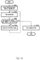
- FIG. 10 is a flowchart showing a reception
processing operation of the receiving apparatus
according to the third embodiment;
- FIG. 11 is a block diagram showing a
configuration of a receiving apparatus according to
the fourth embodiment of the present invention;
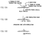
- FIG. 12A is a schematic view showing one example
of a delay profile generated by a delay profile
generating section 105 of the receiving apparatus
according to the fourth embodiment;
- FIG. 12B is a schematic view showing the content
of a spreading code auto-correlation value stored
by an odd correlation phase storage section of the
receiving apparatus according to the forth
embodiment;
- FIG. 12C is a schematic view showing a method
for calculating a candidate peak phase using a
candidate peak phase calculating section 1002 of the
receiving apparatus according to the fourth
embodiment; and
- FIG. 13 is a flowchart showing a reception
processing operation of the receiving apparatus
according to the fourth embodiment.
-
Best Mode for Carrying Out the Invention
-
Embodiments of the present invention will be
specifically explained with reference to the
accompanying drawings. The embodiments to be set
forth below are divided into a first mode wherein
a peak phase of a certain transmitting station is
detected after eliminating a correlation component,
which exerts an influence upon the detection of a
peak correlation value of the transmitting station,
from a delay profile and a second mode wherein a peak
phase of a certain transmitting station is detected
in consideration of a correlation component of the
transmitting station or other transmitting station,
which exerts an influence upon the detection of a
peak correlation value of the transmitting station.
The first embodiment corresponds to the first mode,
and the second to fourth embodiments correspond to
the second mode.
(First embodiment)
-
FIG. 2 is a block diagram showing the
configuration of the receiving apparatus according
to the first embodiment of the present invention.
In FIG. 2, a radio receiving section 102 converts
signals received via an antenna 101 to received
baseband signals, and outputs the received baseband
signals to a correlation calculating section 103 and
a baseband demodulating section 112. In this case,
the signals received via the antenna 101 are those
that are obtained by multiplexing the signals
transmitted from a plurality of transmitting stations
into the same frequency band.
-
The correlation calculating section 103
multiplies the received signals by the known
spreading code as shifting the phase of the received
baseband signals, and calculates correlation values
of the respective phases. As correlation calculating
section 103, for example, a matched filer or a sliding
correlator is used. In this case, the known spreading
code is the same spreading code as used in a spread
processing time at each transmitting station.
-
In order to suppress noise components included
in the correlation values sent from the correlation
calculating section 103 or a correlation eliminating
section 110 via a selecting section 104, a delay
profile generating section 105 generates a delay
profile after providing average processing to the
correlation values. Then, the delay profile
generating section 105 outputs the generated delay
profile to a peak detecting section 106.
-
The peak detecting section 106 detects a maximum
value (hereinafter referred to as "peak correlation
value) of the correlation values averaged in the
delay profile sent via the selecting section 104,
and also detects a phase (hereinafter referred to
as "peak phase") of the detected peak correlation
values of the delay profile. It should be noted that
a baseband demodulating section 112 to be described
later provides despread processing to the received
baseband signals in accordance with the peak phase
thus detected, making it possible to demodulate the
signals transmitted from the respective transmitting
stations. Furthermore, the peak detecting
section 106 outputs the detected peak phase to a
correlation phase adjusting section 107 and a demodulation
control section 111, and also outputs the
detected peak correlation value to a weighting
section 109.
-
A correlation storage section 108 stores
spreading code auto-correlation values beforehand,
and outputs the stored spreading code auto-correlation
values to the correlation phase
adjusting section 107. The spreading code auto-correlation
values are those that are obtained by
multiplying the known spreading code by the phase
of the known spreading code as being shifted to
calculate the correlation value for each phase.
-
The correlation phase adjusting section 107
adjusts the phases of the spreading code auto-correlation
values sent from the correlation storage
section 108 using the peak phase sent from the peak
detecting section 106, and outputs the spreading
code auto-correlation values subjected to the phase
adjustment to the weighting section 109.
-
The weighting section 109 adjusts amplitude of
the correlation values in the spreading code
auto-correlation values subjected to the phase
adjustment sent from the correlation phase adjusting
section 107 by use of the peak correlation value sent
from the peak detecting section 106. Then, the
weighting section 109 outputs the spreading code
auto-correlation values subjected to the phase
adjustment to the correlation eliminating section
110. The correlation eliminating section 110 performs
a subtraction between the correlation values
sent from the correlation calculating section 103
and the spreading code auto-correlation values
subjected to the amplitude adjustment sent from the
weighting section 109. Then, the correlation
eliminating section 110 outputs the subtraction
result.
-
The demodulation control section 111 stores the
peak phase sent from the peak detecting section 106,
and outputs a timing signal for demodulating the
signals sent from the respective transmitting
stations, and outputs it to the baseband
demodulating section 112. The baseband demodulating
section 112 provides despread processing to the
received baseband signals sent from the radio receiving
section 102 to output demodulation data
corresponding to each transmitting station based on
the timing signal sent from the demodulation control
section 111.
-
In this embodiment, before detecting the peak
correlation value of a certain transmitting station,
the auto-correlation component of a transmitting
station in which the peak correlation value and peak
phase are already detected is eliminated from the
correlation value calculated by the correlation
calculating section. Resultantly, the original peak
correlation value of the transmitting station whose
reception field intensity is low has the maximum
correlation value in connection with the correlation
values calculated by the correlation calculating
section. This makes it possible to detect the
original peak correlation value and peak phase,
which correspond to the transmitting station.
-
An explanation will be next given of the
operation of the above-structured receiving
apparatus with reference to FIG. 3 in addition to
FIG. 2. FIG. 3 is a schematic view showing the content
of processing provided to the correlation values
from the correlation calculating section in the
receiving apparatus according to the first
embodiment of the present invention. Though the
following will explain, as one example, the case of
detecting the peak phase corresponding to the second
transmitting station having reception field
intensity lower than that of the first transmitting
station, the present invention can detect the peak
phase corresponding to the other transmitting
station.
-
First, in FIG. 2, the signals transmitted from
the respective transmitting stations are received
via the antenna 101, and then outputted to the radio
receiving section 102. The radio receiving section
102 converts the signals received via the antenna
101 to received baseband signals. The received
baseband signals are outputted to the correlation
calculating section 103. The correlation
calculating section 103 provides despread
processing using the same known spreading code as
used in spread processing at the transmitting
station, and calculates the correlation value for
each phase.
-
The correlation values are input to the delay
profile generating section 105 from the correlation
calculating section 103 or the correlation
eliminating section 110 via the selecting section
104. First, the correlation values calculated by the
correlation calculating section 103 are inputted to
the delay profile generating section 105 by the
selecting section 104.
-
In the delay profile generating section 105,
the above correlation values are subjected to
average processing to suppress noise components
contained in the correlation values outputted from
the correlation calculating section 103, thereby a
delay profile is generated. The generated delay
profile is outputted to the peak detecting section
106.
-
The peak detecting section 106 detects a peak
correlation value and a peak phase in the delay
profile outputted from the delay profile generating
section 105. The peak correlation value and peak
phase detected at this time will be explained with
reference to FIG. 3A.
-
FIG. 3A is a schematic view showing one example
of the delay profile generated by the delay profile
generating section 105 of the receiving apparatus
according to the first embodiment. As shown in FIG.
3A, there exists the correlation value averaged for
each phase. Hereinafter, it is assumed that the
original peak correlation value corresponding to
each of the first and second transmitting stations
appears in the phase as shown in FIG. 3A.
-
The peak detecting section 106 detects the
correlation value, which corresponds to the first
transmitting station and which is the maximum value,
as the peak correlation value in the delay profile
shown in FIG. 3A. Then, the phase of this peak
correlation value is detected as the peak phase. The
peak phase corresponding to the first transmitting
station is outputted to the correlation phase adjusting
section 107 and the demodulation control
section 111. The peak correlation value
corresponding to the first transmitting station is
outputted to the weighting section 109.
-
Thereafter, a spreading code auto-correlation
value is outputted to the correlation phase
adjusting section 107 from the correlation storage
section 108. The spreading code auto-correlation
value will be explained with reference to FIG. 3B.
FIG. 3B is a schematic view showing the spreading
code auto-correlation value stored by the
correlation storage section 108 of the receiving
apparatus according to the first embodiment.
-
The spreading code auto-correlation value is a
collection of the correlation values for the
respective phases, which are obtained by multiplying
the known spreading code and the spreading code,
which is the same as the known spreading code, as
shifting the phase. Namely, the delay profile is
obtained by providing despread processing to the
received signals containing only a signal sent from
a certain transmitting station by use of the known
spreading code. The delay profile thus obtained is
equivalent to the delay profile in which amplitude
and phase of each correlation value in the spreading
code auto-correlation value are changed.
-
In the correlation phase adjusting section 107,
the spreading code auto-correlation values sent from
the correlation storage section 108 are subjected
to phase adjustment using the peak phase, which is
sent from the peak detecting section 106 and which
corresponds to the first transmitting station. The
phase adjustment at this time will be explained with
reference to FIG. 3C. FIG. 3C is a schematic view
showing the spreading code auto-correlation value
subjected to phase adjustment by the correlation
phase adjusting section 107 of the receiving
apparatus according to the first embodiment.
-
Namely, the phases of the spreading code
auto-correlation values shown in FIG. 3B are
adjusted such that the phase of the maximum
correlation value in this spreading code auto-correlation
values matches the peak phase corresponding
to the first transmitting station shown in
FIG. 3A. This adjustment changes the phases of the
spreading code auto-correlation values shown in FIG.
3B as shown in FIG. 3C. Since the auto-correlation
function is repeated with a cycle when the spreading
code is used, the spreading code auto-correlation
values are subjected to the phase adjustment by being
circulated in an arrow direction shown in FIG. 3C.
The spreading code auto-correlation values
subjected to the phase adjustment are outputted to
the weighting section 109.
-
The weighting section 109 provides amplitude
adjustment to the spreading code auto-correlation
value subjected to the phase adjustment sent from
the correlation phase adjusting section 107 by use
of the peak correlation value, which is sent from
the peak detecting section 106 and which corresponds
to the first transmitting station. The amplitude
adjustment at this time will be explained with
reference to FIG. 3D. FIG. 3D is a schematic view
showing the spreading code auto-correlation values
subjected to amplitude adjustment by the weighting
section 109 of the receiving apparatus according to
the first embodiment.
-
First, the maximum correlation value in the
spreading code auto-correlation values is subjected
to amplitude adjustment to be equal to the peak
correlation value, which is sent from the peak
detecting section 106 and which corresponds to the
first transmitting station.
-
Moreover, the correlation values other than the
maximum value in the spreading code auto-correlation
value are subjected to amplitude adjustment based
on the ratio in value between the maximum value and
the peak correlation value corresponding to the
first transmitting station. In other words, the
correlation values other than the maximum value are
reduced or increased by the ratio at which the maximum
value is reduced or increased.
-
The spreading code auto-correlation values
subjected to the phase adjustment shown in FIG. 3C
are changed as shown in FIG. 3D by this adjustment.
It can be said that the spreading code auto-correlation
values thus obtained are equivalent to
the fact as follows. That is, auto-correlation
components of the first transmitting station, which
are included in the delay profile generated by the
delay profile generating section 105, are produced
in a quasi-manner. The auto-correlation components
of the first transmitting station are the
correlation values, which are obtained when despread
processing is provided to the received signals sent
from only the first transmitting station using the
known spreading code. The spreading code auto-correlation
values subjected to amplitude adjustment
are outputted to the correlation eliminating
section 110.
-
The correlation eliminating section 110 performs
a subtraction between the correlation values
sent from the correlation calculating section and
the spreading code auto-correlation values
subjected to the amplitude adjustment sent from the
weighting section. Namely, the spreading code
auto-correlation values subjected to amplitude
adjustment are subtracted from the correlation
values sent from the correlation calculating section.
This makes it possible to eliminate the auto-correlation
components of the signal from the detected
transmitting station, that is, the first
transmitting station, from the correlation values
calculated by the correlation calculating section
103. The subtraction result at this time will be
explained with reference to FIG. 3E.
-
FIG. 3E is a schematic view showing a delay
profile in which the auto-correlation components of
the first transmitting station are eliminated by the
correlation eliminating section 110 of the receiving
apparatus according to the first embodiment. The
spreading code auto-correlation values subjected to
the amplitude adjustment shown in FIG. 3D are
subtracted from the delay profile shown in FIG. 3A.
This obtains the delay profile in which the
auto-correlation components of the first
transmitting station are eliminated as shown in FIG.
3E.
-
This makes it clear that the correlation value
other than the peak correlation value of the second
transmitting station exists as the highest
correlation value next to the peak correlation value
of the first transmitting station in the correlation
values of the delay profile before eliminating the
auto-correlation component of the first transmitting
station as shown in FIG. 3A. While, in the
correlation values of the delay profile after
eliminating the auto-correlation components of the
first transmitting station as shown in FIG. 3E, the
peak correlation value of the second transmitting
station becomes a maximum value. In other words, the
auto-correlation components of the first
transmitting station are prevented from being
erroneously detected at the time of detecting the
peak correlation value of the second transmitting
station.
-
Next, in place of the correlation values
calculated by the correlation values calculating
section 103, the correlation values in which the
auto-correlation components of the first
transmitting station are eliminated by the
correlation eliminating section 110 is outputted to
the delay profile generating section 105 by the
selecting section 104.
-
Thereafter, the peak detecting section 106
correctly detects the peak correlation value and
peak phase corresponding to the second transmitting
station. Then, the aforementioned processing is
performed using the detection result. As a result,
the auto-correlation components of the second
transmitting station in addition to the first
transmitting station are eliminated from the
correlation values calculated by the correlation
calculating section 103. The peak correlation value
and peak phase corresponding to a certain
transmitting station are detected in the same way
afterward.
-
On the other hand, the demodulation control
section 111 stores the peak phase corresponding to
each detected transmitting station. All peak
correlation values and peak phases corresponding to
a certain transmitting stations are detected in this
way. Thereafter, a timing signal for demodulating
the signals transmitted from the respective
transmitting stations are outputted to the baseband
demodulating section 112 from the demodulation
control section 111. In the baseband demodulating
section 112, despread processing is provided to the
received baseband signal from the radio receiving
section 102 based on the timing signal from the
demodulation control section 111, with the result
that modulation data corresponding to each
transmitting station can be obtained.
-
The flow of the operation of the above-configured
receiving apparatus will be next explained
with reference to FIG. 4. FIG. 4 is a
flowchart showing the reception processing operation
of the receiving apparatus according to the
first embodiment.
-
First, in step (hereinafter referred to as "ST")
301, the signals received via the antenna 102 are
converted to received baseband signals. Moreover,
a correlation between the received baseband signals
and the known spreading code is obtained by the
correlation calculating section 103. In ST302, the
correlation values calculated by the correlation
calculating section 102 are sent to the delay profile
generating section 105 by the selecting section 104.
-
In ST303, the delay profile generating section
105 generates a delay profile. Thereafter, peak
detecting section 106 detects the peak correlation
value and peak phase in the delay profile. The
detected peak phase is stored in the demodulation
control section 111.
-
In ST304, it is confirmed whether or not the peak
correlation values and peak phases, which correspond
to all transmitting stations to be detected, are
detected. The transmitting stations to be detected
are given using, for example, the number, or the
threshold value in a reception level value of the
peak correlation value and the like. When the peak
correlation values and peak phases, which correspond
to all transmitting stations, are detected,
processing goes to ST308. Conversely, when they are
not detected, processing goes to ST305.
-
In ST305, the correlation phase adjusting
section 107 provides phase adjustment to the
spreading code auto-correlation values outputted
from the correlation storage section 108 in
accordance with the detected peak phase. Also, the
weighting section 109 provides phase adjustment to
the spreading code auto-correlation values
subjected to the phase adjustment in accordance with
the amplitude of the detected peak correlation value.
Whereby, auto-correlation components of the
detected transmitting station, which are included
in the correlation values obtained by the
correlation calculating section 103, are produced
in a quasi-manner.
-
In ST306, the correlation eliminating section
110 eliminates the auto-correlation components of
the detected transmitting station from the
correlation values calculated by the correlation
calculating section 103. In ST307, in place of the
correlation values from the correlation calculating
section 103, the correlation value from the
correlation eliminating section 110 are sent to the
delay profile generating section 105 by the
selecting section 110.
-
Afterward, processing goes back to ST303 and the
above-mentioned processing is repeated.
-
While, in ST308, a timing signal for
demodulating the signals transmitted from the respective
transmitting stations are outputted to the
baseband demodulating section 112 from the
demodulation control section 111. In the baseband
demodulating section 112, despread processing is
provided to the received baseband signal from the
radio receiving section 102 based on the timing
signal from the demodulation control section 111,
with the result that modulation data corresponding
to each transmitting station can be obtained.
-
Thus, even in a case where the reception field
intensity of the signal from the second transmitting
station is lower than that of the signal from the
first transmitting station, the correlation value
between the received signal from the first
transmitting station and the spreading code is
generated in a quasi-manner. Then, the correlation
values generated in a quasi-manner are eliminated
from the correlation values calculated by the
correlation calculating section 103. This eliminates
the auto-correlation components of the first
transmitting station from the correlation values
calculated by the correlation calculating section
103.
-
As a result, in the correlation values
calculated by the correlation calculating section
103, the original peak correlation value
corresponding to the second transmitting station
becomes a maximum value as a correlation value. For
this reason, the peak correlation value is detected
by the peak detecting section 106. Therefore, the
peak correlation value and peak phase corresponding
to the second transmitting station are correctly
detected.
-
Thus, according to this embodiment, even in a
case where variations occur in the reception field
intensity of the signals from the respective
transmitting stations, the auto-correlation
components of the detected transmitting station are
generated in a quasi-manner using the auto-correlation
values calculated beforehand using the
known spreading code. Then, the generated auto-correlation
components are eliminated from the
correlation values of the delay profile. This makes
it possible to correctly detect the peak phase with
a small number of calculations in connection with
the transmitting station whose reception field
intensity is lower than that of the above-detected
transmitting station.
(Second embodiment)
-
According to the embodiment, in the delay
profile generated by resulting from the variation
in the reception field intensity of the signals from
the respective transmitting stations, there exists
a quasi-peak having a value larger than the original
peak correlation value of each transmitting station.
For this reason, the peak phase of the transmitting
station is detected in consideration of the phase
of the quasi-peak. Whereby, the signal from the
transmitting station can be correctly demodulated
even in a case where a quasi-peak is erroneously
detected as a peak correlation value of the
transmitting station. The following will explain the
receiving apparatus of the second embodiment with
reference to FIG. 5.
-
FIG. 5 is a block diagram showing the
configuration of the receiving apparatus according
to the second embodiment of the present Invention.
In FIG. 5, regarding the configuration of each of
the antenna 101, radio receiving section 102,
correlation calculating section 103, delay profile
generating section 105, and peak detecting section
106, they are the same as those of the first
embodiment (FIG. 2), and the specific examination
is omitted.
-
Regarding the phase (hereinafter referred to as
"quasi-peak phase") corresponding to the quasi-peak
having a large value in the despreading code
auto-correlation values of the aforementioned first
embodiment.
-
A quasi-peak phase storage section 402 stores
a phase difference between the quasi-peak phase and
the original peak correlation value. It should be
noted that the spreading code auto-correlation
values themselves are the same as those stored by
the correlation storage section 108 of the
aforementioned embodiment 1.
-
Namely, the quasi-peak phase storage section
402 sets a predetermined threshold value. Then, the
quasi-peak phase storage section 402 stores the
phase difference, as a quasi-peak phase, between the
quasi-peak having the correlation value more than
the threshold value and the original peak
correlation value in the spreading code auto-correlation
values. Beside the above, the quasi-peak
phase storage section 402 may store only a
predetermined number of the quasi-peak phases set
in order of decreasing correlation value. The
quasi-peak phase storage section 402 outputs the
stored quasi-peak phases to a peak phase adjusting
section 401.
-
The peak phase adjusting section 401 calculates
a peak phases to be assumed as an original peak phase
(hereinafter referred to as "candidate peak phase" )
based on the quasi-peak phases from the quasi-peak
phase storage section 402 and the peak phases from
the peak detecting section 106. Namely, the peak
phase adjusting section 401 calculates the original
peak phase as a candidate peak phase assuming that
the peak phase from the peak detecting section 106
is a quasi-peak having a large correlation value of
some degree. Moreover, the peak phase adjusting
section 401 outputs the calculated candidate peak
phase to the demodulation control section 403.
-
Herein, the method for calculating the candidate
peak phase will be described with reference to
FIG. 6. FIG. 6 is a schematic view showing one example
of a delay profile generated by the receiving
apparatus according to the second embodiment. In the
delay profile shown in FIG. 6, there exists a
quasi-peak, which is higher than the original peak
correlation value corresponding to a certain
transmitting station in the delay profile shown in
FIG. 6.
-
The phase difference, as a quasi-peak phase,
between the quasi-peak and the original peak
correlation value shown in FIG. 6 is sent to the peak
phase adjusting section 401 from the quasi-peak
phase storage section 402. Here, it is assumed that
the quasi-peak phase is + 2chip. The peak phase
adjusting section 401 calculates the original peak
phase, which is obtained when not the original peak
correlation value but the quasi-peak is detected by
the peak detecting section 106, as a candidate peak
phase.
-
More specifically, for example, if the peak
phase (detected phase), which is obtained when the
quasi-peak shown in FIG. 6 is detected as a peak
correlation value, is 27chip, the calculation of
27-2 = 25chip is established as a candidate peak phase.
The peak phase adjusting section 401 outputs the
candidate peak phase thus calculated to the
demodulation control section 403. Regarding the
respective quasi-peaks sent from the quasi-peak
phase storage section 402, it is needless to say that
the candidate peak phase is calculated and outputted
to the demodulation control section 403.
-
The demodulation control section 403 stores the
peak phases from the peak detecting section 106 and
the candidate peak phases from the peak phase
adjusting section 401. First, the demodulation
control section 403 outputs a timing signal for
demodulating the signal transmitted from the
transmitting station, which corresponds to the peak
phase, to a baseband demodulation section 404 based
on the peak phases from the peak detecting section
106.
-
Thereafter, when the demodulation control
section 403 receives the determination in which the
demodulation result, which is based on the timing
signal, is an error from the baseband demodulation
section 404, the demodulation control section 403
judges that the peak phase has been the quasi-peak
and outputs the timing signal, which is based on the
candidate peak phase, to the baseband modulation
section 404. Moreover, the demodulation control
section 403 outputs the timing signal, which is based
on the other candidate peak phase, to the baseband
modulation section 404 when receiving the same
determination as mentioned above from the baseband
demodulation section 404.
-
The baseband demodulation section 404 provides
despread processing to the received baseband signal
sent from the radio receiving section 102 based on
the timing signal sent from the demodulation control
section 403, whereby outputting demodulation data
corresponding to each transmitting station. At this
time, the baseband demodulation section 404
determines the correctness/error of the demodulation
result and outputs the determination result to
the demodulation control section 403.
-
The operation of the above-configured receiving
apparatus will be next described with reference to
FIG. 7.
-
FIG. 7 is a flowchart showing a reception
processing operation of the receiving apparatus
according to the second embodiment.
-
First, in ST601, the signals received via the
antenna 101 are converted to baseband signals.
Moreover, the correlation calculating section 103
obtains the correlation between the received
baseband signal and the known spreading code. Also,
the delay profile generating section 105 generates
a delay profile. In ST602, the peak detecting section
106 detects peak phases in the delay profile. The
detected peak phases are stored in the demodulation
control section 403.
-
In ST603, the peak phase adjusting section 401
calculates a candidate peak phase using the
quasi-peak phases sent from the quasi-peak phase
storage section 402.
-
In ST604, the demodulation control section 403
outputs a timing signal, which is based on the peak
phase from the peak detecting section 106, to the
baseband demodulation section 404. The baseband
demodulation section 404 demodulates the received
baseband signal sent from the radio receiving
section 102 based on the timing signal sent from the
demodulation control section 402. Thereafter, the
demodulation result is outputted to the demodulation
control section 403 from the baseband demodulation
section 404.
-
In ST605, the demodulation control section 403
performs the determination of the demodulation
result from the baseband demodulation section 404.
When the demodulation result is correct, processing
goes to ST607. Conversely, when the demodulation
result is incorrect, processing goes to ST606.
-
In ST606, the demodulation control section 403
outputs the timing signal to the baseband
demodulation section 404 again. The timing signal
at this time is a signal, which is obtained based
on the candidate peak phase sent from the peak phase
adjusting section 401. The baseband demodulation
section 205 demodulates the received baseband signal
based on the timing signal obtained at the candidate
peak phase. After the demodulation, the demodulation
result is outputted to the demodulation control
section 403 from the baseband demodulation section
205. After that, processing goes back to ST604.
-
In ST607, the demodulation control section 403
determines that the peak phase, which corresponds
to the transmitting station to be subjected to
demodulation by the baseband demodulation section
404, has been correctly detected. Therefore, the
baseband demodulation section 404 continues to
perform demodulation processing to the received
baseband signal.
-
Thus, according to this embodiment, there is a
case that a quasi-peak, which has a value more than
the original peak correlation value of a certain
transmitting station, exists due to variations in
the reception field intensity of the signal from the
transmitting station at the delay profile generating
time. Even in such a case, the phase difference
between the quasi-peak phase with a correlation
value of some degree and the original peak
correlation value based on the spreading code
auto-correlation value stored beforehand. The
candidate peak phase is calculated using this phase
difference. Moreover, by referring to the
demodulation result based on the timing signal
obtained by the detected peak phase and the candidate
peak phase, it is possible to correctly detect the
original correlation value peak of the transmitting
station.
-
Furthermore, the correlation storage section
108 in the aforementioned first embodiment must
store the spread code auto-correlation values, while
the quasi-peak phase storage section 402 in this
embodiment stores only the phase of the quasi-peak
in the spread code auto-correlation value. In this
embodiment, it is possible to suppress the necessary
memory quantity as compared with the first
embodiment.
(Third embodiment)
-
According to this embodiment, even in a case
where variations occur in reception field intensity
of the signals from the respective transmitting
stations, the peak phase of a certain transmitting
station can be correctly detected as considering the
phases of the correlation components of the other
transmitting station with high reception field
intensity, which exerts an influence upon the
detection of the peak correlation value of the
transmitting station. The following will explain the
receiving apparatus according to the third
embodiment with reference to FIG. 8.
-
FIG. 8 is a block diagram showing the
configuration of the receiving apparatus according
to the third embodiment of the present invention.
In FIG. 8, regarding the configuration of each of
the antenna 101, radio receiving section 102,
correlation calculating section 103, delay profile
generating section 105, demodulation control section
111 and baseband demodulation section 112, they
are the same as those of the first embodiment (FIG.
2). Moreover, the quasi-peak phase storage section
402 is the same as that of the second embodiment (FIG.
5), and the specific examination is omitted.
-
A peak detecting section 701 detects peak phases
in the delay profile sent from the delay profile
generating section 105, and outputs the detection
result to a quasi-peak phase adjusting section 702
and a demodulation control section 111. However, the
peak detecting section 701 does not detect the peak
phases subjected to the detection by the previous
processing again. Namely, the peak detecting section
701 detects the peak phases other than the detected
peak phases sent from the quasi-peak phase adjusting
section 702.
-
The quasi-peak phase adjusting section 702
calculates the quasi-peak of the transmitting
station corresponding to the above-detected peak
phase using the peak phases detected by the peak
detecting section 701 and the quasi-peaks from the
quasi-peak phase storage section 402. Herein, the
method for calculating the quasi-peak using the
quasi-peak phase adjusting section 702 will be
explained with reference to FIG. 9.
-
FIG. 9A is a schematic view showing one example
of the delay profile generated by the delay profile
generating section 105 of the receiving apparatus
according to the third embodiment. FIG. 9B is a
schematic view showing the content of the spreading
code auto-correlation value stored by the quasi-peak
phase storage section 402 of the receiving
apparatus according to the third embodiment. FIG.
9C is a schematic view showing a method for
calculating the quasi-peak phase using the
quasi-peak phase adjusting section 702 of the receiving
apparatus according to the third embodiment.
-
When the delay profile as shown in FIG. 9A is
generated by the delay profile generating section
105, the peak correlation value at phase C corresponding
to the second transmitting station should
be primarily detected as a peak correlation value
after detecting the peak correlation value at phase
A corresponding to the first transmitting station.
-
However, since the reception field intensity of
the signal from the second transmitting station is
lower than that of the signal from the first
transmitting station, the original peak correlation
value of the second transmitting station becomes
smaller than the auto-correlation component of the
signal from the first transmitting station, that is,
the quasi-peak at phase B shown in FIG. 9A. For this
reason, the quasi-peak at phase B is detected after
detecting the peak correlation value corresponding
to the first transmitting station.
-
Here, first, according to this embodiment, the
quasi-peak phase storage section 402 outputs the
quasi-peak phase of the spreading code auto-correlation
value to the quasi-peak phase adjusting
section 702 as shown in FIG. 9B. FIG. 9B shows one
example in which the quasi-peak phase of the
quasi-peak shown in FIG.9A is calculated as 2chip.
-
Moreover, the quasi-peak phase adjusting section
702 calculates the phases of the auto-correlation
components (quasi-peaks) of the signal
from the first transmitting station in the delay
profile using the peak correlation values detected
by the peak detecting section 701 and the quasi-peak
phases from the quasi-peak phase storage
section 402. For example, when the peak phase of the
first transmitting station shown in FIG. 9A is
detected as 25chip by the peak detecting section 701,
the peak phase shown in FIG. 9A is calculated as 25+2
chip as shown in FIG. 9C.
-
After detecting the peak phase of the first
transmitting station, the correlation value at the
phase of the quasi-peak thus calculated is designed
not to be detected. Whereby, the peak phase of the
second transmitting station can be next detected.
The above has explained the method for calculating
the quasi-peak using the quasi-peak phase adjusting
section 702.
-
The quasi-peak phase adjusting section 702
outputs the peak phase detected by the peak detecting
section 701 and the phase of the calculated
quasi-peak to the peak detecting section 701. The
peak detecting section 701 does not detect the
detected peak correlation value of the transmitting
station and the quasi-peak of the signal from the
transmitting station as the peak correlation value
at a next peak detecting time.
-
The operation of the above-configured receiving
apparatus will be next explained using the flowchart
of FIG. 10. FIG. 10 is a flowchart showing a reception
processing operation of the receiving apparatus
according to the third embodiment.
-
First, in ST901, the signals received via the
antenna 101 are converted to baseband signals by the
radio receiving section 102. Moreover, the
correlation between the received baseband signal and
the known spreading code is obtained by the
correlation calculating section 103. Also, the delay
profile is generated by the delay profile generating
section 105.
-
In ST902, the peak detecting section 701 detects
the peak phase in the delay profile. At a first
detecting time, since the peak phases, which are
already detected, are inputted, a simple detection
for a maximum value is performed. At second detecting
time and afterward, since the peak phases, which are
already detected, are inputted, the maximum value,
except for the correlation value at the phase, is
detected. The detected peak phases are stored in the
demodulation control section 111.
-
In ST903, it is conformed whether or not the peak
correlation values and the peak phases, which
correspond to all transmitting stations to be detected,
are detected. The transmitting stations to
be detected are given using, for example, the number,
or the threshold value in a reception level value
of the peak correlation value and the like. When the
peak correlation values and peak phases, which
correspond to all transmitting stations, are detected,
processing goes to ST905. Conversely, when
they are not detected, processing goes to ST904.
-
In ST904, the quasi-peak phase adjusting section
702 calculates the quasi-peak phase in
accordance with the detected peak phase. Moreover,
the quasi-peak phase adjusting section 702 outputs
the above peak phase and quasi-peak phase to the peak
detecting section 701 as the detected phases. After
that, processing goes to ST902.
-
In ST905, the demodulation control section 111
outputs a timing signal for demodulating the signals
from the respective transmitting stations to the
baseband demodulation section 112. The baseband
demodulation section 112 provides despread
processing to the received baseband signal from the
radio receiving section 102 based on the timing
signal from the demodulation control section 111.
This obtains demodulation data corresponding to each
transmitting station.
-
Thus, even in a case where the reception field
intensity of the signal from the second transmitting
station is lower that that of the signal from the
first transmitting station, the peak phase corresponding
to the first transmitting station is detected.
After that, the phase in which the auto-correlation
value of the signal from the first
transmitting station increases is calculated. Then,
at the time of detecting the peak phase corresponding
to the second transmitting station, the calculated
phase is excluded to carry out the detection. Whereby,
the original peak correlation value of the second
transmitting station is correctly detected even if
it is small.
-
Moreover, the quasi-peak phase storage section
402 in this embodiment stores only the phase of the
quasi-peak in the spread code auto-correlation
values similar to the second embodiment. For this
reason, in this embodiment, it is possible to
suppress the necessary memory quantity as compared
with the first embodiment.
-
Thus, according to this embodiment, even in a
case where variations occur in reception field
intensity of the signals from the respective
transmitting stations, the phase of the quasi-peak
of the signal from the detected transmitting station
is calculated using the auto-correlation value
calculated beforehand by use of the known spreading
code. Then, at the next peak phase detecting time
and afterward, the peak phase except for the
calculated phase is detected. This makes it possible
to detect the peak phase with a small number of
calculations with respect to the transmitting
station whose reception field intensity is lower
than that of the detected transmitting station.
(Fourth embodiment)
-
According to this embodiment, the original peak
phase of a certain transmitting station matches the
phase of an odd correlation component with a large
correlation value of the signal from the other
transmitting station. Whereby, even in a case where
the entire correlation value in this phase becomes
small, the original peak phase of the transmitting
station can be detected inconsideration of the odd
correlation component of the other transmitting
station. The following will explain the receiving
apparatus according to the fourth embodiment with
reference to FIG.11.
-
It is assumed that an odd correlation component
with a large value is included in the correlation
components of an other transmitting station and that
the phase of the odd correlation component matches
the peak phase of a certain transmitting station.
In this case, since the correlation value of the
transmitting station at this phase in the delay
profile becomes small, there is a possibility that
the peak phase of the transmitting station will not
be correctly detected.
-
For this reason, according to this embodiment,
first, the phase of the odd correlation component
in the spreading code auto-correlation value is
stored, and the phase of the odd correlation
component is adjusted in accordance with the peak
phase of the detected transmitting station. Whereby,
the phase of the odd correlation component of the
detected transmitting station in the delay profile
is calculated. Thereafter, when the correlation
value at the phase in the delay profile exceeds the
threshold value, this phase is detected as a peak
phase of the transmitting station. FIG. 11 is a block
diagram showing the configuration of the receiving
apparatus according to the fourth embodiment of the
present invention. In FIG. 11, regarding the configuration
of each of the antenna 101, radio
receiving section 102, correlation calculating
section 103, delay profile generating section 105,
demodulation control section 111 and baseband demodulation
section 112, they are the same as those
of the first embodiment (FIG. 2) and the specific
examination is omitted.
-
A peak detecting section 1001 inputs a candidate
peak phase to be described later from a candidate
peak phase calculating section 1002. Also, in the
delay profile sent from the delay profile generating
section 105, the peak detecting section 1001 detects
a peak phase and outputs it to the quasi-peak phase
calculating section 1002 and the modulation control
section 111. Moreover, if the correlation value at
the inputted candidate peak phase has a value of some
degree though it is not always the maximum value in
the correlation value of the delay profile, the peak
detecting section 1001 outputs the candidate peak
phase to the quasi-peak phase calculating section
1002 as a peak phase.
-
At this time, as to whether or not the candidate
peak phase is selected as a peak phase, for example,
a threshold value, which is larger by 3dB than the
average value of the correlation values in the delay
profile. Then, a candidate peak phase, which exceeds
this threshold value, may be determined as a peak
phase.
-
An odd correlation phase storage section 1003
stores a phase of an odd correlation value in the
spreading code auto-correlation value of the
aforementioned first embodiment. In other words, it
stores a phase of a correlation value whose negative
absolute value is large as an odd correlation phase.
The spreading code auto-correlation values themselves
are the same as those stored by the correlation
storage section 108 of the aforementioned first
embodiment. As phases to be stored, for example, a
certain threshold value is set and phases, each
having a correlation value lower than the threshold
value, may be stored. Beside the above, the odd
correlation phase storage section 1003 may store
only a predetermined number of odd correlation
phases set in order of increasing the correlation
values in the spreading code auto-correlation value.
The odd correlation phase storage section 1003
outputs the stored odd correlation phases to the
candidate peak phase calculating section 1002.
-
The candidate peak phase calculating section
1002 calculates a candidate peak phase using the peak
phase detected by the peak detecting section 1001
and the odd correlation phase from the odd
correlation phase storage section 1003, and outputs
the calculation result to the peak detecting section
1001. Here, a method for calculating the candidate
peak phase using the candidate peak phase
calculating section 1002 will be explain with
reference to FIG. 12.
-
FIG. 12A is a schematic view showing one example
of the delay profile generated by the delay profile
generating section 105 of the receiving apparatus
according to the fourth embodiment. FIG. 12B is a
schematic view showing the content of a spreading
code auto-correlation value stored by the odd
correlation phase storage section 1003 of the receiving
apparatus according to the forth embodiment.
FIG. 12C is a schematic view showing a method for
calculating a candidate peak phase using the
candidate peak phase calculating section 1002 of the
receiving apparatus according to the fourth
embodiment.
-
When the delay profile as shown in FIG. 12A is
generated by the delay profile generating section
105, a peak correlation value at phase A
corresponding to the first transmitting station is
detected. Thereafter, a quasi-peak at phase B is
detected. Here, when an odd correlation component
of the signal from the first transmitting station
matches a peak correlation value of the second
transmitting station, there is a possibility that
a peak correlation value at phase C corresponding
to the second transmitting station will become small.
Namely, there is a possibility that the peak
correlation value corresponding to the second
transmitting station should be originally detected
after detecting the peak correlation value at phase
A corresponding to the first transmitting station.
-
For this reason, according to this embodiment,
first, the odd correlation phase storage section
1003 outputs the phase of the odd correlation value
(odd correlation phase), which has a correlation
value lower than the threshold value in the spreading
code auto-correlation values as shown in FIG. 12B,
to the candidate peak phase calculating section 1002.
FIG. 12B shows one example in which the odd
correlation phase corresponding to the peak phase
of the second base station shown in FIG. 12A is
calculated as 3chip.
-
Moreover, it is assumed that the odd correlation
phase from the odd correlation phase storage section
1003 and the peak phase of a certain transmitting
station whose reception field intensity is lower
than that of the first transmitting station are
overlapped with each other. Then, the candidate peak
phase calculating section 1002 calculates a
candidate peek phase using the peak correlation
value of the first transmitting station detected by
the peak detecting section 1001 and the odd
correlation phase. For example, when the peak phase
of the first transmitting station shown in FIG. 12A
is detected as 25 chip by the peak detecting section
1001, the peak phase of the second transmitting
station shown in FIG. 12A, that is, the candidate
peak phase is calculated as 25+3chip as shown in FIG.
12C.
-
After the peak detecting section 1001 detects
the peak phase of the first transmitting station.
the candidate peak phase calculating section 1002
outputs the candidate peak phase thus calculated to
the peak detecting section 1001. Then, the peak
detecting section 1001 detects the candidate peak
phase as a peak phase. Whereby, the peak phase of
the second transmitting station is next detected.
The above has explained the method for calculating
the candidate peak phase using the candidate peak
phase calculating section 1002.
-
The operation of the above-configured receiving
apparatus will be next explained using the flowchart
of FIG. 13. FIG. 13 is a flowchart showing a reception
processing operation of the receiving apparatus
according to the fourth embodiment.
-
First, in ST1201, the signals received via the
antenna 101 are converted to baseband signals by the
radio receiving section 102. Moreover, the
correlation between the received baseband signal and
the known spreading code is obtained by the
correlation calculating section 103. Also, the delay
profile is generated by the delay profile generating
section 105.
-
In ST1202, the peak detecting section 401 detects
the peak phases in the delay profile. At a first
detecting time, since the peak phases, which are
already detected, are not stored, a simple detection
for a maximum value is performed and the phases of
the detected correlation values are stored. At
second detecting time and afterward, since the peak
phases, which are already detected, are stored, the
maximum value, except for the correlation value at
the phase, is detected. Moreover, at the second
detecting time and afterward, the correlation values
at the candidate peak phase from the candidate peak
phase calculating section 1002 are detected as peak
phases if they are more than the threshold value.
The detected peak phase is stored in the demodulation
control section 111.
-
In ST1203, it is conformed whether or not the
peak correlation values and the peak phases, which
correspond to all transmitting stations to be detected,
are detected. The transmitting stations to
be detected are given using, for example, the number,
or the threshold value in a reception level value
of the peak correlation value and the like. When the
peak correlation values and peak phases, which
correspond to all transmitting stations, are detected,
processing goes to ST1205. Conversely, when
they are not detected, processing goes to ST1204.
-
In ST1204, the candidate peak phase calculating
section 1002 adjusts the odd correlation phase in
accordance with the detected peak phase and
calculates the candidate peak phase, and outputs the
calculation result to the peak detecting section
1001. After that, processing goes to ST1202.
-
In ST1205, the demodulation control section 111
outputs a timing signal for demodulating the signals
from the respective transmitting stations to the
baseband demodulation section 112. The baseband
demodulation section 112 provides despread
processing to the received baseband signal form the
radio receiving section 102 based on the timing
signal from the demodulation control section 111.
This obtains demodulation data corresponding to each
transmitting station.
-
As mentioned above, even when the original peak
phase of the second transmitting station and the
phase of the odd correlation component of the first
transmitting station match each other, this phase
is used as a candidate peak phase. When the
correlation value at this candidate peak phase has
a value of some degree, this candidate peak phase
is detected as a peak phase of the second transmitting
station. This makes it possible to detect the peak
phase of the second transmitting station without
fail even if the correlation value of the second
transmitting station is small.
-
In this way, according to this embodiment, even
when the phase of the peak correlation value of a
certain transmitting station matches the phase of
the odd correlation component having a large
correlation value of the signal from the other
transmitting station, the phase of the odd
correlation component of the signal of the other
transmitting station is calculated using the
auto-correlation values calculated beforehand by
use of the known spreading code. Then, at the time
of detecting the peak phase of the transmitting
station, a phase of a peak which has the correlation
value of some degree at the calculated phase, is
detected as a peak phase. This makes it possible to
detect the peak phase of the transmitting station
correctly with a small number of calculations even
if the original peak correlation value of the
transmitting station is small.
-
Moreover, the
correlation storage section 108
of the first embodiment needs to store the spreading
code auto-correlation values. In contrast, the odd
correlation
phase storage section 1003 of this
embodiment stores only the phase of the odd
correlation in the spreading code auto-correlation
values. For this reason, this embodiment makes it
possible to suppress the necessary memory quantity
as compared with the first embodiment.
- 1 ○ The receiving apparatus of the present
invention adopts a configuration comprising: delay
profile generating means for generating a delay
profile using correlation values calculated based
on a received signal and a known spreading code;
auto-correlation value calculating means for
calculating auto-correlation values of the known
spreading code; and demodulation timing detecting
means for detecting demodulation timing of a certain
transmitting station from the delay profile using
the auto correlation values.
According to this configuration, the auto-correlation
components of the certain transmitting
station can be eliminated from the delay profile
using the auto-correlation values of the known
spreading code calculated beforehand. Also, the
auto-correlation components of the certain transmitting
station In the delay profile can be estimated.
This makes it possible to correctly detect the peak
phase of the certain transmitting station.
- 2 ○ The receiving apparatus of the present
invention adopts a configuration wherein the
demodulation timing detecting means comprises
auto-correlation component calculating means for
calculating auto-correlation components of a
transmitting station from the auto-correlation
values based on a peak phase and a peak correlation
value of the transmitting station whose demodulation
timing is already detected in the delay profile;
eliminating means for eliminating the auto-correlation
components of the transmitting station
from the delay profile; and peak phase detecting
means for detecting a peak phase of a certain
transmitting station which is in a non-detection
state, from the delay profile in which the auto-correlation
components of the transmitting station
are eliminated.
According to this configuration, even in a case
where variations occur in reception field intensity
of the signals from the respective transmitting
stations, the auto-correlation components of the
detected transmitting station are calculated using
the auto-correlation values calculated beforehand
by use of the known spreading code. The calculated
auto-correlation components are eliminated from the
correlation values in the delay profile. This makes
it possible to detect the peak phase accurately with
a small number of calculations in connection with
the transmitting station whose reception field
intensity is lower than that of the detected
transmitting station.
- 3 ○ The receiving apparatus of the present
invention adopts a configuration wherein the
demodulation timing detecting means comprises phase
difference storage means for storing a phase
difference between a peak correlation value and a
quasi-peak correlation value in the auto-correlation
values; candidate peak phase
calculating means for calculating a candidate peak
phase from the phase difference based on a peak phase
of a certain transmitting station whose demodulation
timing is already detected in the delay profile; and
peak phase determining means for determining the
peak phase of the certain transmitting station based
on a demodulation result with demodulation timing
at the candidate peak phase.
According to this configuration, there is a case
that a quasi-peak, which has a value more than the
original peak correlation value of a certain
transmitting station, exists due to variations in
the reception field intensity of the signal from the
transmitting station at the delay profile generating
time. Even in such a case, the phase difference
between the quasi-peak phase with a correlation
value of some degree and the original peak
correlation value based on the spreading code
auto-correlation value stored beforehand. The
candidate peak phase is calculated using this phase
difference. Moreover, by referring to the
demodulation result based on the timing signal
obtained by the detected peak phase and the candidate
peak phase, it is possible to correctly detect the
original correlation value peak of the transmitting
station.
- 4 ○ The receiving apparatus of the present
invention adopts a configuration wherein the
demodulation timing detecting means comprises phase
difference storage means for storing a phase
difference between a peak correlation value and a
quasi-peak correlation value in the auto-correlation
values; quasi-peak phase calculating
means for calculating a phase of a quasi-peak of a
transmitting station whose demodulation timing is
already detected from the phase difference based on
a peak phase of the transmitting station in the delay
profile; and peak phase detecting means for detecting
a peak phase of a transmitting station which
is in a non-detection state, from the phases other
than the quasi-peak in the delay profile.
According to this configuration, even in a case
where variations occur in reception field intensity
of the signals from the respective the transmitting
stations, the phase of the quasi-peak of the signal
from the detected the transmitting station is
calculated using the auto-correlation values
calculated beforehand by use of the known spreading
code. Then, at the next peak phase detecting time
and afterward, the peak phase except for the
calculated phase is detected. This makes it possible
to detect the peak phase with a small number of
calculations with respect to the transmitting
station whose reception field intensity is lower
than that of the detected the transmitting station.
- 5 ○ The receiving apparatus of the present
invention adopts a configuration wherein the
demodulation timing detecting means comprises phase
difference storage means for storing a phase
difference between a peak correlation value and an
odd correlation value in the auto-correlation
values; odd correlation phase calculating means for
calculating an odd phase of a transmitting station
whose demodulation timing is already detected from
the phase difference based on a peak phase of the
communication in the delay profile; and peak phase
detecting means for detecting the odd correlation
phase as a peak phase of the transmitting station
which is in a non-detection state, when the
correlation value at the odd correlation phase in
the delay profile is more than a threshold value.
According to this configuration, even when the
peak correlation value of a certain transmitting
station matches the odd correlation component having
a large correlation value of the signal from the other
transmitting station, the phase of the odd
correlation component of the signal of the other
transmitting station is calculated using the
auto-correlation value calculated beforehand by use
of the known spreading code. Then, at the time of
detecting the peak phase of the transmitting station,
one, which has the correlation value of some degree
at the calculated phase, is detected as a peak phase.
This makes it possible to detect the peak phase of
the transmitting station correctly with a small
number of calculations even if the original peak
correlation value of the transmitting station is
small.
- 6 ○ The radio communication terminal apparatus
of the present invention adopts a configuration
having a receiving apparatus wherein the receiving
apparatus comprises delay profile generating means
for generating a delay profile using correlation
values calculated based on a received signal and a
known spreading code, auto-correlation value
calculating means for calculating auto-correlation
values of the known spreading code, and demodulation
timing detecting means for detecting demodulation
timing of a certain transmitting station from the
delay profile using the auto correlation values.
According to this configuration, the provision
of the receiving apparatus, which can correctly
detect the peak phase of the transmitting station
with a small number of calculations, and which makes
it possible to provide the radio communication
terminal apparatus, which performs synchronization
capturing correctly.
- 7 ○ The base station apparatus of the present
invention adopts a configuration, which performs
radio communication with a radio communication
terminal apparatus having a receiving apparatus,
wherein the receiving apparatus comprises delay
profile generating means for generating a delay
profile using correlation values calculated based
on a received signal and a known spreading code,
auto-correlation value calculating means for
calculating auto-correlation values of the known
spreading code, and demodulation timing detecting
means for detecting demodulation timing of a certain
transmitting station from the delay profile using
the auto correlation values.
According to this configuration, radio
communication with the radio communication terminal
apparatus, which performs synchronization capturing
correctly, is carried out, whereby making it possible
to provide the base station apparatus, which
performs good communication.
- 8 ○ The synchronization capturing method of the
present invention adopts a method comprising the
steps of generating a delay profile using
correlation values calculated based on a received
signal and a known spreading code, calculating
auto-correlation values of the known spreading code,
calculating auto-correlation components of a
transmitting station whose demodulation timing is
already detected using the auto-correlation values,
eliminating the auto-correlation components from
the delay profile, and detecting a peak phase of a
certain transmitting station from the delay profile
in which the auto-correlation components of the
transmitting station are eliminated.
According to this method, even in a case where
variations occur in reception field intensity of the
signals from the respective transmitting stations,
the auto-correlation components of the detected
transmitting station are calculated using the
auto-correlation values calculated beforehand by
use of the known spreading code. The calculated
auto-correlation components are eliminated from the
correlation value in the delay profile. This makes
it possible to detect the peak phase accurately with
a small number of calculations in connection with
the transmitting station whose reception field
intensity is lower than that of the detected
transmitting station.
- 9 ○ A synchronization capturing method of the
present invention adopts a method comprising the
steps of generating a delay profile using
correlation values calculated based on a received
signal and a known spreading code, calculating
auto-correlation values of the known spreading code,
storing a phase difference between a peak
correlation value and a quasi-peak correlation value
or an odd correlation phase in the auto-correlation
values, detecting a peak phase of a certain
transmitting station from the delay profile based
on a peak phase detected from the delay file and the
phase difference.
According to this method, the peak phase of the
certain transmitting station is detected in
consideration of the phase of the correlation
component of the certain transmitting station or the
other transmitting station, which exerts an
influence upon the detection of the peak correlation
value of the certain transmitting station. This
makes it possible to correctly detect the peak phase
with a small number of calculations.In addition, the receiving apparatus according
to the above embodiment can be applied to the radio
communication terminal apparatus and the base
station apparatus in the digital radio communication
system.As explained above, the auto-correlation
components of the transmitting station in the delay
profile are calculated using the auto-correlation
values of the known spreading code calculated beforehand.
Then, the peak phase of the transmitting
station to be demodulated is detected in
consideration of the calculated auto-correlation
components. This makes it possible to provide the
receiving apparatus, which can correctly detect the
original peak phase, which corresponds to each
transmitting station, with a small number of
calculations.In addition, the receiving apparatus according
to the above embodiment can be applied to the radio
communication terminal apparatus and the base
station apparatus in the digital radio communication
system.
-
-
This application is based on the Japanese Patent
Application No. HEI 11-110180 filed on April 16, 1999,
entire content of which is expressly incorporated
by reference herein.
Industrial Applicability
-
This invention is suitable for use in the CDMA
communication field.