EP1098215B1 - Catadioptric objective comprising two intermediate images - Google Patents
Catadioptric objective comprising two intermediate images Download PDFInfo
- Publication number
- EP1098215B1 EP1098215B1 EP00122738A EP00122738A EP1098215B1 EP 1098215 B1 EP1098215 B1 EP 1098215B1 EP 00122738 A EP00122738 A EP 00122738A EP 00122738 A EP00122738 A EP 00122738A EP 1098215 B1 EP1098215 B1 EP 1098215B1
- Authority
- EP
- European Patent Office
- Prior art keywords
- objective
- partial
- objective according
- image
- lens
- Prior art date
- Legal status (The legal status is an assumption and is not a legal conclusion. Google has not performed a legal analysis and makes no representation as to the accuracy of the status listed.)
- Expired - Lifetime
Links
- 210000001747 pupil Anatomy 0.000 claims description 14
- 230000003287 optical effect Effects 0.000 claims description 10
- 239000000463 material Substances 0.000 claims description 8
- 230000005499 meniscus Effects 0.000 claims description 8
- 239000013078 crystal Substances 0.000 claims description 4
- 150000002222 fluorine compounds Chemical class 0.000 claims description 2
- 239000000758 substrate Substances 0.000 claims 2
- KRHYYFGTRYWZRS-UHFFFAOYSA-M Fluoride anion Chemical compound [F-] KRHYYFGTRYWZRS-UHFFFAOYSA-M 0.000 claims 1
- 238000012937 correction Methods 0.000 description 19
- 238000013461 design Methods 0.000 description 12
- WUKWITHWXAAZEY-UHFFFAOYSA-L calcium difluoride Chemical compound [F-].[F-].[Ca+2] WUKWITHWXAAZEY-UHFFFAOYSA-L 0.000 description 9
- 229910001634 calcium fluoride Inorganic materials 0.000 description 7
- 238000003384 imaging method Methods 0.000 description 7
- 230000000694 effects Effects 0.000 description 5
- 238000001393 microlithography Methods 0.000 description 5
- 230000004075 alteration Effects 0.000 description 4
- 238000010276 construction Methods 0.000 description 4
- 210000001624 hip Anatomy 0.000 description 4
- 239000010436 fluorite Substances 0.000 description 3
- VYPSYNLAJGMNEJ-UHFFFAOYSA-N silicon dioxide Inorganic materials O=[Si]=O VYPSYNLAJGMNEJ-UHFFFAOYSA-N 0.000 description 3
- 230000003595 spectral effect Effects 0.000 description 3
- OYLGJCQECKOTOL-UHFFFAOYSA-L barium fluoride Chemical compound [F-].[F-].[Ba+2] OYLGJCQECKOTOL-UHFFFAOYSA-L 0.000 description 2
- 229910001632 barium fluoride Inorganic materials 0.000 description 2
- 230000003247 decreasing effect Effects 0.000 description 2
- 239000011521 glass Substances 0.000 description 2
- 238000005286 illumination Methods 0.000 description 2
- PUZPDOWCWNUUKD-UHFFFAOYSA-M sodium fluoride Chemical compound [F-].[Na+] PUZPDOWCWNUUKD-UHFFFAOYSA-M 0.000 description 2
- 206010010071 Coma Diseases 0.000 description 1
- 238000010521 absorption reaction Methods 0.000 description 1
- 230000006978 adaptation Effects 0.000 description 1
- 230000005540 biological transmission Effects 0.000 description 1
- 230000008602 contraction Effects 0.000 description 1
- 230000001419 dependent effect Effects 0.000 description 1
- 238000007689 inspection Methods 0.000 description 1
- 238000004519 manufacturing process Methods 0.000 description 1
- 238000000386 microscopy Methods 0.000 description 1
- 238000012986 modification Methods 0.000 description 1
- 230000004048 modification Effects 0.000 description 1
- 239000010453 quartz Substances 0.000 description 1
- FVRNDBHWWSPNOM-UHFFFAOYSA-L strontium fluoride Chemical compound [F-].[F-].[Sr+2] FVRNDBHWWSPNOM-UHFFFAOYSA-L 0.000 description 1
- 229910001637 strontium fluoride Inorganic materials 0.000 description 1
- 238000012360 testing method Methods 0.000 description 1
- 238000012546 transfer Methods 0.000 description 1
- 238000001429 visible spectrum Methods 0.000 description 1
- 230000000007 visual effect Effects 0.000 description 1
Images

Classifications
-
- G—PHYSICS
- G02—OPTICS
- G02B—OPTICAL ELEMENTS, SYSTEMS OR APPARATUS
- G02B17/00—Systems with reflecting surfaces, with or without refracting elements
-
- G—PHYSICS
- G02—OPTICS
- G02B—OPTICAL ELEMENTS, SYSTEMS OR APPARATUS
- G02B17/00—Systems with reflecting surfaces, with or without refracting elements
- G02B17/08—Catadioptric systems
- G02B17/0892—Catadioptric systems specially adapted for the UV
-
- G—PHYSICS
- G02—OPTICS
- G02B—OPTICAL ELEMENTS, SYSTEMS OR APPARATUS
- G02B17/00—Systems with reflecting surfaces, with or without refracting elements
- G02B17/08—Catadioptric systems
- G02B17/0804—Catadioptric systems using two curved mirrors
- G02B17/0812—Catadioptric systems using two curved mirrors off-axis or unobscured systems in which all of the mirrors share a common axis of rotational symmetry
-
- G—PHYSICS
- G03—PHOTOGRAPHY; CINEMATOGRAPHY; ANALOGOUS TECHNIQUES USING WAVES OTHER THAN OPTICAL WAVES; ELECTROGRAPHY; HOLOGRAPHY
- G03F—PHOTOMECHANICAL PRODUCTION OF TEXTURED OR PATTERNED SURFACES, e.g. FOR PRINTING, FOR PROCESSING OF SEMICONDUCTOR DEVICES; MATERIALS THEREFOR; ORIGINALS THEREFOR; APPARATUS SPECIALLY ADAPTED THEREFOR
- G03F7/00—Photomechanical, e.g. photolithographic, production of textured or patterned surfaces, e.g. printing surfaces; Materials therefor, e.g. comprising photoresists; Apparatus specially adapted therefor
- G03F7/70—Microphotolithographic exposure; Apparatus therefor
- G03F7/70216—Mask projection systems
- G03F7/70225—Optical aspects of catadioptric systems, i.e. comprising reflective and refractive elements
-
- G—PHYSICS
- G03—PHOTOGRAPHY; CINEMATOGRAPHY; ANALOGOUS TECHNIQUES USING WAVES OTHER THAN OPTICAL WAVES; ELECTROGRAPHY; HOLOGRAPHY
- G03F—PHOTOMECHANICAL PRODUCTION OF TEXTURED OR PATTERNED SURFACES, e.g. FOR PRINTING, FOR PROCESSING OF SEMICONDUCTOR DEVICES; MATERIALS THEREFOR; ORIGINALS THEREFOR; APPARATUS SPECIALLY ADAPTED THEREFOR
- G03F7/00—Photomechanical, e.g. photolithographic, production of textured or patterned surfaces, e.g. printing surfaces; Materials therefor, e.g. comprising photoresists; Apparatus specially adapted therefor
- G03F7/70—Microphotolithographic exposure; Apparatus therefor
- G03F7/70216—Mask projection systems
- G03F7/70275—Multiple projection paths, e.g. array of projection systems, microlens projection systems or tandem projection systems
Definitions
- the invention is related to an objective comprising a partial objective having two opposing concave mirrors with central bores.
- Catadioptric objectives with one intermediate image and a refractive partial objective are known as microlithographic projection systems with axial symmetry and central obscuration from US 5,488,229 to Elliott and Shafer and from above mentioned DE 196 39 586.
- Schuster shows only the mirrors to be aspherical and avoids big lenses in the beam path between them.
- a microlithographic projection exposure system with a catadioptric objective comprising two intermediate images is known.
- the objective shown there in Fig. 12 comprises two catoptric partial objectives and one catadioptric partial objective. All objectives are off-axis, not axially symmetric, purely spherical systems.
- US 5,004,331 to Haseltine et al. discloses a catadioptric projector for projecting an image to a dome (of a flight simulator).
- the system comprises an external entrance pupil as means for receiving substantially collimated light, a refractive subsystem of rotationally symmetric, coaxial lenses forming a pupil image which is situated at the central opening of an aspheric concave mirror, which together with another concave mirror forms a reflective pupil relay system. Both mirrors are tilted with respect to the optical axis of the refractive subsystem.
- the whole system provides a wide field of view image on a spherical dome. Full visible spectrum colour correction is obtained by combination of different glass.
- these designs are to be used in the VUV spectral region for microscopy or microlithography.
- a central obscuration in principle has degenerating effects in imaging the reduction of the obscuration by the central hole of the mirrors of this design is of importance.
- Claims 2 and 3 give a preferred way of reducing obscuration by placing the intermediate images in the vicinity of the mirrors.
- Claims 7 and 8 give quantitative limitations of the central openings.
- FIG. 4 Another advantageous form is given in claim 4 which clearly groups the mirrors in one catoptric partial objective, which cooperates with one or more purely refractive partial objectives.
- the catoptric partial objective carries the burden of Petzval sum reduction or field flattening. This relieves the refractive partial objective from the need for beam contractions and expansions by negative and positive lens groups, as is long established with microlithographic projection exposure lenses, see e. g. Glatzel E., ZEISS-Information 26 (1981), p. 8-13, US 5,260,832 or US 5,903,400.
- the refractive partial objective is simplified and the lens diameters are reduced.
- Claims 5 and 6 show an alternative of claim 4, where lenses are inserted between the mirrors. As negative lenses these cooperate with the mirrors to give single material colour correction, relieving the need for band narrowing the laser light source or for using an achromatizing material pair in the VUV.
- the chief ray height at each of the mirror bores is approximately the same in value , but opposite in sign. This measure allows for minimal central obscuration.
- Two refractive and one catadioptric partial objectives is subject of the dependant claim 16.
- the sequence given in claim 13 where the mirror-containing partial objective is framed by the two refractive partial objectives is preferred as it allows for both intermediate image "planes" connected by the mirror containing partial objective to be curved such as to best exploit the specific correction capabilities of this partial objective.
- Claim 27 states that diffractive surfaces, as occasionally also proposed for projection exposure objectives, are also useful with this invention just as they are with refractive designs.
- Axial symmetry together with two intermediate images is subject of the dependant claim 28.
- Such axial symmetric construction of the objective has inter alia advantages in mechanical rigidity and in compatibility with established stepper/scanner architectures adapted to refractive objectives.
- All lenses are made of fluorite CaF 2 and the system is adapted for illumination by the F 2 excimer-laser at 157 mm.
- the first partial objective S1 is refractive and has a reduction ratio of -1/4,27.
- the second partial objective S2 is catadioptric with two opposite concave aspheric mirrors M1, M2 with central holes and two negative meniscus lenses 25, 26 and 27, 28 arranged between them. They are passed by the light beams three times. Its magnification ratio is - 1/0,99. Such a magnification ratio near unity allows for a highly symmetric construction and optimal correction of distortions.
- This arrangement is particularly suitable for chromatic correction and correction of field curvature, too. Therefore even with only one lens material CaF 2 a relatively wide laser bandwith of +-1.2 pm of an unnarrowed F2-laser is accepted by this objective.
- a positive air lens - i. e. an air space in the form of a positive lens - between the lens surfaces 40 and 41 is characteristic.
- the mirror holes are arranged next to the two intermediate images IMI 1 and IMI 2, where the beam diameters are at a minimum. Also the first partial objective S1 has substantial image reduction to keep this hole absolutely small, so that also the total mirror diameter is limited to a practical compact value.
- the mirror holes are sized to be 2,0 mm larger in diameter than the closest ray at the edge of the field.
- a obscuration mask is inserted at the pupil (aperture) plane of the first partial objective S2 - just in front of lens surface 9. This should be sized 20,25 % in diameter - equal to 4,1 % in area. Then the area obscuration at the edge of the field has the same value as at the center and the MTF curves are completely uniform over the field.
- the wavefront correction of this example is better than 0,011 waves rms over the field of 17 x 7 mm 2 and less than 0,009 waves rms over the field of 17 x 6 mm 2 .
- the distortion is 2.4 ppm and the median shift is 10 nm.
- the system is of overall similarity with the first example, but with some significant deviations.
- the first refractive partial objective S 1 has its aperture plane enclosed by two menisci 209, 210 and 211, 212 which are concave towards the aperture plane.
- an obscuring disk OD is inserted for the purpose of field-independent obscuration as described above.
- Two lens surfaces 209 and 217 are aspheric, the first is next to the aperture plane to affect angle deviations and the second is more in the field region.
- the imaging ratio of the first partial objective S1 is -1/4,67. Therefore the catadioptric partial objective can be so small.
- the second partial objective S2 again is catadioptric with two aspheric mirrors M21, M22 and two negative meniscus lenses 223,224 and 225, 226. Now their distance has strongly decreased, but angles increased in the beam path. This allows for very limited diameters of only 230 mm at the given large field and large NA.
- the reduction ratio is -1//0,97. In this embodiment, too, the central obscuration is 20% in diameter constant over the full field.
- the mirrors M21, M22 are aspheric with maximum deviations from sphere being limited to 150 micrometers, which allows for good production and testing.
- a third negative lens here would further optimize colour correction, if needed.
- the third partial objective S3 shows the characteristic first meniscus lens 227,228 to be even more bent than in fig. 1. This helps for coma correction. Also the second lens 229,230 is a meniscus concave on the intermediate image IMI side, as the two final lenses 249,250 and 251,252 are menisci concave towards the image plane Im, what is preferred for aplanatism and correction of spherical aberration.
- the positive air lens arranged between the lens surfaces 238 and 239 corrects the main part of spherical aberration. For this effect it is preferably arranged more in the pupil region of the objective than in a field region. However its arrangement before the pupil plane enables it to affect also the oblique spherical aberration in tangential and sagittal direction.
- lens 245,246 together with the air space created in front of it assists to the effects of the aforementioned air space.
- the imaging ratio of this third partial objective S23 is -1/1,11 near unity.
- the arrangement is far from symmetry to the pupil plane, so that the strongly distorted intermediate image IMI can be transformed to a highly corrected image at the image plane Im.
- S21 performs the reduction
- S22 makes the colour and Petzval correction
- S23 makes the fine tuning of imaging errors.
- This second embodiment is not finely tuned to best error correction, but gives the principles of feasibility of such a design.
- the explanatory example of fig. 3 has a purely catoptric partial objective S31 and a purely refractive partial objective S32 between object Ob and image Im, with only one intermediate image IMI. Therefore the example of fig. 3 is not within the scope of the claims but is helpful to explain the general properties of an objective comprising two intermediate images and a purely catoptric partial objective between the two intermediate images.
- the purely catoptric partial objective avoids the big negative lenses of the catadioptric partial objectives of the aforementioned examples.
- the mirrors M1, M2 now are purely used for Petzval correction - correction of field curvature.
- the chromatic characteristics of the objective are defined by the refractive partial objective S32.
- Use of different lens materials allows for achromatization.
- fluorides namely calcium fluoride (fluorspar, fluorite), barium fluoride, strontium fluoride, NaF, Lif etc. and/or quartz glass, also in specifically doped versions, are adequate.
- positive lenses L1,L3 can be made of calcium fluoride and negative lens L2 can be made of barium fluoride or NaF, for example.
- the refractive partial objective S32 has more lenses in a realistic microlithography or microscope objective and the lenses L1 to L3 shown are only schematic representatives.
- the refractive partial objective S32 of this catadioptric objective as compared to a full refractive system is relieved from the burden of Petzval correction, it can be simplified.
- the waist and bulge configuration with two and more waists of state-of-the-art refractive microlithographic reduction projection objectives is therefore not needed. Only one waist of minor beam reduction remains. Consequently the refractive partial objective S32 can be shorter, smaller in diameter and can have less lenses. Transmission and contrast are thus increased, while cost is decreased. Aspheric lens surfaces further help in this effect.
- the catoptric partial objective S31 is free of lenses, its diameter is not critical: Precision aspherical mirrors with diameters of more than one meter are state of the art in astronomy, for example.
- catoptric and refractive partial objective also can be changed in sequence. Then the diameter of the catoptric partial system is reduced in consequence of the imaging ratio of the refractive partial objective.
- this system also is extended to a first refractive partial objective S41, a catoptric partial objective S42 and a second refractive partial objective S43 with intermediate images IMI1 and IMI2, as shown in the example of fig. 4.
- the mirrors 440 and 441 are aspheric.
- the second bulge comprises one asphere, the second waist one asphere, and the third bulge 2 aspheres.
- the first bulge comprises one asphere, while the second of the two bulges comprises 2 aspheres.
- the objective has a high correction quality, as the wavefront error calculated for two lines of 1 pm spectral distance is less than 8 millilambda at the maximum field height and reduces to less than five millilambda on the optical axis.
- the central obscuration of the system can be designed to need by enlarging distance and diameter of the mirrors 440, 441 of the catoptric partial objective S42.
- Ring sector field imaging is conventional with many catoptric and catadioptric projection exposure systems of generally asymmetric construction. Such can also be realized within the invention. Then, the mirrors only need an off-axis ring sector opening for entering of the light beam, and consequently the pupil only has a two sector obscuration with further reduced effects compared to the circular central obscuration.
- Fig. 5 schematically shows a microscope with an objective according to the invention.
- the objective is constituted by two refractive partial objectives S51, S53 and the intermediate catoptric or catadioptric partial objective S52.
- the example shows two coaxial opposite mirrors M1, M2 and one negative lens L in it.
- the design of the objective is generally as shown in the embodiments described above, but with image and object plane exchanged to obtain magnification, and with higher imaging ratio and smaller field.
Description
- The invention is related to an objective comprising a partial objective having two opposing concave mirrors with central bores.
- Such is known from DE 196 39 586 (US ser. No. 09/263,788) to Schuster.
- Catadioptric objectives with one intermediate image and a refractive partial objective are known as microlithographic projection systems with axial symmetry and central obscuration from US 5,488,229 to Elliott and Shafer and from above mentioned DE 196 39 586.
- Elliott and Shafer show the intermediate image near to the central opening of one of the mirrors, and lenses are arranged in the light path between the mirrors forming Mangin mirrors. All their optical surfaces are spherical.
- Schuster shows only the mirrors to be aspherical and avoids big lenses in the beam path between them.
- From US 4,701,035 to Hirose a microlithographic projection exposure system with a catadioptric objective comprising two intermediate images is known. The objective shown there in Fig. 12 comprises two catoptric partial objectives and one catadioptric partial objective. All objectives are off-axis, not axially symmetric, purely spherical systems.
- US 5,004,331 to Haseltine et al. discloses a catadioptric projector for projecting an image to a dome (of a flight simulator). The system comprises an external entrance pupil as means for receiving substantially collimated light, a refractive subsystem of rotationally symmetric, coaxial lenses forming a pupil image which is situated at the central opening of an aspheric concave mirror, which together with another concave mirror forms a reflective pupil relay system. Both mirrors are tilted with respect to the optical axis of the refractive subsystem. The whole system provides a wide field of view image on a spherical dome. Full visible spectrum colour correction is obtained by combination of different glass.
- It is an object of the invention to provide new design alternatives for objectives comprising a partial objective having two opposing concave mirrors with central bores which allow for high resolution objectives with reduced lens diameters and high performance. Advantageously these designs are to be used in the VUV spectral region for microscopy or microlithography. As a central obscuration in principle has degenerating effects in imaging the reduction of the obscuration by the central hole of the mirrors of this design is of importance.
- The solution of this problem is obtained by the objective according to
claim 1. - Preferred embodiments and advantageous forms of the invention are subjects of the
dependent claims 2 to 32. -
Claims 2 and 3 give a preferred way of reducing obscuration by placing the intermediate images in the vicinity of the mirrors.Claims - Another advantageous form is given in claim 4 which clearly groups the mirrors in one catoptric partial objective, which cooperates with one or more purely refractive partial objectives. In this case it is provided that the catoptric partial objective carries the burden of Petzval sum reduction or field flattening. This relieves the refractive partial objective from the need for beam contractions and expansions by negative and positive lens groups, as is long established with microlithographic projection exposure lenses, see e. g. Glatzel E., ZEISS-Information 26 (1981), p. 8-13, US 5,260,832 or US 5,903,400. In consequence the refractive partial objective is simplified and the lens diameters are reduced. Especially for the proposed use in the VUV spectral region this gives great relief to the materials supply of suitable crystals or quartz glasses.
-
Claims 5 and 6 show an alternative of claim 4, where lenses are inserted between the mirrors. As negative lenses these cooperate with the mirrors to give single material colour correction, relieving the need for band narrowing the laser light source or for using an achromatizing material pair in the VUV. - According to claim 9 it is especially advantageous that the chief ray height at each of the mirror bores is approximately the same in value , but opposite in sign. This measure allows for minimal central
obscuration. - While it is rather conventional that mirrors are aspheric also in the related art, in
claim 10 it is specifically stated that aspheric lens surfaces prove advantageous with this design. All advantages and restrictions as recently established for refractive projection exposure objectives, see e. g. patent application DE 199 92 209 of Schuster and references cited therein hold also for the use of aspheric surfaces in the designs of this invention. - Two refractive and one catadioptric partial objectives is subject of the
dependant claim 16. The sequence given inclaim 13 where the mirror-containing partial objective is framed by the two refractive partial objectives is preferred as it allows for both intermediate image "planes" connected by the mirror containing partial objective to be curved such as to best exploit the specific correction capabilities of this partial objective. -
Claim 27 states that diffractive surfaces, as occasionally also proposed for projection exposure objectives, are also useful with this invention just as they are with refractive designs. - Axial symmetry together with two intermediate images is subject of the
dependant claim 28. Such axial symmetric construction of the objective has inter alia advantages in mechanical rigidity and in compatibility with established stepper/scanner architectures adapted to refractive objectives. - Other advantageous varieties and properties of the invention are subject of
claims 17 to 28. According toclaims 29 and 30 such objectives are preferably part of microscope or a microlithographic projection exposure system.Claim 31 likewise gives the advantageous use of such objective for microlithographic projection exposure.Claim 32 gives an advantageous way of microlithography using an objective according to preceding claims. - The invention is described in more detail based on the examples shown in the drawings.
- Fig. 1
- shows the lens section of an example of an objective with a refractive, a catadioptric, a second refractive partial objective in sequence, reduction ratio 1 : 6
- Fig 2
- shows another example of such an objective with reduction ratio 1 : 5
- Fig 3
- shows a schematic explanatory lens arrangement of an objective with a purely catoptric partial objective of axial symmetry which does not form part of the invention.
- Fig 4
- shows another example of the invention with a refractive, a catoptric, a second refractive partial objective in sequence.
- Fig 5
- shows schematically a microscope with an objective according to the invention
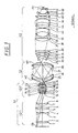
- The example of Fig 1 is a 6 : 1 reduction objective for a scanner projection exposure apparatus of microlithography, with an image field diameter of 18.4 mm , an image side NA = 0.75, being telecentric in the object space and the image space.
- All lenses are made of fluorite CaF2 and the system is adapted for illumination by the F2 excimer-laser at 157 mm.
- Certainly modifications for other wavelengths with other materials are possible, e. g. 193 nm and quartz glass.
- The first partial objective S1 is refractive and has a reduction ratio of -1/4,27.
- It shows two distinct lens groups LG1 of four relatively big lenses of about 130 mm diameter, and after the aperture plane a second lens group LG 2 with significantly reduced diameter of about 80 mm and less. Here, the only aspheric lens surface is provided on surface 9 immediately subsequent to the aperture plane. Subsequent to the first
intermediate image IMI 1, the second partial objective S2 is catadioptric with two opposite concave aspheric mirrors M1, M2 with central holes and twonegative meniscus lenses
Such a magnification ratio near unity allows for a highly symmetric construction and optimal correction of distortions. - This arrangement is particularly suitable for chromatic correction and correction of field curvature, too. Therefore even with only one lens material CaF2 a relatively wide laser bandwith of +-1.2 pm of an unnarrowed F2-laser is accepted by this objective.
- Subsequent to the second intermediate image IMI2 the third partial objective S3 again is refracti ve.
- It takes up the divergent light beam with a strongly
bent meniscus 29,30. A positive air lens - i. e. an air space in the form of a positive lens - between the lens surfaces 40 and 41 is characteristic. - With its reduction ratio of -1/1,42 the overall reduction ratio of the system is reached.
- The detailed data of Table 1 show that the objective is composed of relatively few elements of limited diameters which helps for practical feasibility, as CaF2 is very expensive and of limited availability. Also the light path in CaF2 is limited, thus reducing the problem of significant absorption at 157 mm.
- The central obscuration necessitated by the fully coaxial construction of the catadioptric second partial objective S2 is a certain drawback, as such in principle deteriorates the modulation transfer function of an objective.
- However, even in common refractive projection exposure objectives a small but distinct central obscuration is entered to accomodate beam paths of alignment systems etc.
- Efforts are taken in the design to keep the central obscuration small, even with mirror diameters of practical size.
- It was found that the diameter of the holes in the mirrors is minimized when the chief ray height is of equal value at the two holes, but opposite in sign.
- Further the mirror holes are arranged next to the two
intermediate images IMI 1 andIMI 2, where the beam diameters are at a minimum. Also the first partial objective S1 has substantial image reduction to keep this hole absolutely small, so that also the total mirror diameter is limited to a practical compact value. - The mirror holes are sized to be 2,0 mm larger in diameter than the closest ray at the edge of the field.
- It is recommended that a obscuration mask is inserted at the pupil (aperture) plane of the first partial objective S2 - just in front of lens surface 9. This should be sized 20,25 % in diameter - equal to 4,1 % in area. Then the area obscuration at the edge of the field has the same value as at the center and the MTF curves are completely uniform over the field.
- The wavefront correction of this example is better than 0,011 waves rms over the field of 17 x 7 mm2 and less than 0,009 waves rms over the field of 17 x 6 mm2. The distortion is 2.4 ppm and the median shift is 10 nm.
- Colour correction reaches CHL = 34 nm/pm for longitudinal colour, so that a +-1.2 pm bandwidth of an unnarrowed F2-laser can be accepted.
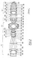
- The example of fig. 2 and table 2 has an increased image field of 22 x 9 mm2 as well as a significantly increased NA = 0,75, while the reduction ratio is changed to 5 : 1. The system is of overall similarity with the first example, but with some significant deviations.
- The first refractive partial
objective S 1 has its aperture plane enclosed by twomenisci - Two
lens surfaces - The imaging ratio of the first partial objective S1 is -1/4,67. Therefore the catadioptric partial objective can be so small.
- The second partial objective S2 again is catadioptric with two aspheric mirrors M21, M22 and two negative meniscus lenses 223,224 and 225, 226. Now their distance has strongly decreased, but angles increased in the beam path. This allows for very limited diameters of only 230 mm at the given large field and large NA. The reduction ratio is -1//0,97. In this embodiment, too, the central obscuration is 20% in diameter constant over the full field.
- High NA of 0,7 at the intermediate images to allow for the small holes in the mirrors M21, M22 and a rather strong refractive power of the lenses 223,224 and 225,226 in between to give the required colour correction are specific to this example.
- The mirrors M21, M22 are aspheric with maximum deviations from sphere being limited to 150 micrometers, which allows for good production and testing.
- Also on the lenses between the mirrors aspheric surfaces could increase image quality. A third negative lens here would further optimize colour correction, if needed.
- The third partial objective S3 shows the characteristic first meniscus lens 227,228 to be even more bent than in fig. 1. This helps for coma correction. Also the second lens 229,230 is a meniscus concave on the intermediate image IMI side, as the two final lenses 249,250 and 251,252 are menisci concave towards the image plane Im, what is preferred for aplanatism and correction of spherical aberration.
- The positive air lens arranged between the lens surfaces 238 and 239 corrects the main part of spherical aberration. For this effect it is preferably arranged more in the pupil region of the objective than in a field region. However its arrangement before the pupil plane enables it to affect also the oblique spherical aberration in tangential and sagittal direction.
- As a meniscus concave toward the pupil plane, lens 245,246 together with the air space created in front of it assists to the effects of the aforementioned air space.
- The imaging ratio of this third partial objective S23 is -1/1,11 near unity. However, the arrangement is far from symmetry to the pupil plane, so that the strongly distorted intermediate image IMI can be transformed to a highly corrected image at the image plane Im.
- Each partial objective has its part of the burden: S21 performs the reduction, S22 makes the colour and Petzval correction and S23 makes the fine tuning of imaging errors.
- This second embodiment is not finely tuned to best error correction, but gives the principles of feasibility of such a design.
- The aspheric surfaces of both examples of tables 1 and 2 are described by
- The explanatory example of fig. 3 has a purely catoptric partial objective S31 and a purely refractive partial objective S32 between object Ob and image Im, with only one intermediate image IMI. Therefore the example of fig. 3 is not within the scope of the claims but is helpful to explain the general properties of an objective comprising two intermediate images and a purely catoptric partial objective between the two intermediate images. The purely catoptric partial objective avoids the big negative lenses of the catadioptric partial objectives of the aforementioned examples. The mirrors M1, M2 now are purely used for Petzval correction - correction of field curvature.
- The chromatic characteristics of the objective are defined by the refractive partial objective S32. Use of different lens materials allows for achromatization. For DUV/VUV excimer laser systems combinations of fluorides, namely calcium fluoride (fluorspar, fluorite), barium fluoride, strontium fluoride, NaF, Lif etc. and/or quartz glass, also in specifically doped versions, are adequate. Thus, for microlithography at 157 nm, positive lenses L1,L3 can be made of calcium fluoride and negative lens L2 can be made of barium fluoride or NaF, for example.
- Naturally the refractive partial objective S32 has more lenses in a realistic microlithography or microscope objective and the lenses L1 to L3 shown are only schematic representatives.
- As the refractive partial objective S32 of this catadioptric objective as compared to a full refractive system is relieved from the burden of Petzval correction, it can be simplified. The waist and bulge configuration with two and more waists of state-of-the-art refractive microlithographic reduction projection objectives is therefore not needed. Only one waist of minor beam reduction remains. Consequently the refractive partial objective S32 can be shorter, smaller in diameter and can have less lenses. Transmission and contrast are thus increased, while cost is decreased. Aspheric lens surfaces further help in this effect.
- As the catoptric partial objective S31 is free of lenses, its diameter is not critical: Precision aspherical mirrors with diameters of more than one meter are state of the art in astronomy, for example.
- Obviously the arrangement of catoptric and refractive partial objective also can be changed in sequence. Then the diameter of the catoptric partial system is reduced in consequence of the imaging ratio of the refractive partial objective.
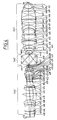
- For reasons of good accessibility of object Ob and image Im and of more design space for correction, it is advantageous if this system also is extended to a first refractive partial objective S41, a catoptric partial objective S42 and a second refractive partial objective S43 with intermediate images IMI1 and IMI2, as shown in the example of fig. 4.
- The advantages of the first two embodiments with minimal obscuration and of the third example without big lenses between the mirrors M1, M2 can thus be combined.
- Table 3 gives the design data of this example. This is a 157nm objective with all crystal lenses, most of LiF and some of NaF, giving excellent chromatic properties for an unnarrowed F2 laser with 1,5 pm band width. Reduction ratio is 1 :5, maximum image field height is 11,88 mm, NA = 0,75. Maximum lens diameter is 190,5 mm, maximum mirror diameter is 201 mm. The overall length Ob-Im is 1,459 m.
- The use of crystal lenses in DUV to VUV microlithographic objectives is made here in adaptation of the earlier application DE 199 29 701.0 dated June 29, 1999 (99032 P) of coinventor Schuster and the same assignee.
- Consequently, negative NaF lenses are entered, plus one
positive NaF meniscus - Aspheric surfaces are entered into this design at a number of surfaces, where this is advantageous. Consequently, also the
mirrors third bulge 2 aspheres. In the third partial objective S43 the first bulge comprises one asphere, while the second of the two bulges comprises 2 aspheres. - The aspheric surfaces of the example of tab. 3 are described by

- Where P is the height deviation as a function of the radius h (ray height with respect to the optical axis) with the aspheric constants C1 to C6 as given in table 3. δ is the inverse of the radius given in the table.
- The objective has a high correction quality, as the wavefront error calculated for two lines of 1 pm spectral distance is less than 8 millilambda at the maximum field height and reduces to less than five millilambda on the optical axis.
- The central obscuration of the system can be designed to need by enlarging distance and diameter of the
mirrors - Ring sector field imaging is conventional with many catoptric and catadioptric projection exposure systems of generally asymmetric construction. Such can also be realized within the invention. Then, the mirrors only need an off-axis ring sector opening for entering of the light beam, and consequently the pupil only has a two sector obscuration with further reduced effects compared to the circular central obscuration.
- Fig. 5 schematically shows a microscope with an objective according to the invention.
- As such primarily makes sense for a DUV/VUV inspection microscope, direct visual observation by an ocular is not shown, but an image detector CCD of any appropriate known sort is provided in the image plane of the objective. The objective is constituted by two refractive partial objectives S51, S53 and the intermediate catoptric or catadioptric partial objective S52. The example shows two coaxial opposite mirrors M1, M2 and one negative lens L in it.
- The design of the objective is generally as shown in the embodiments described above, but with image and object plane exchanged to obtain magnification, and with higher imaging ratio and smaller field.
- An illumination system Ill illuminates the object Ob appropriately.
0,75 N.A., -2= 157 nm, β = 6X, 17 x 7 mm double-telecentric Element RADIUS [mm] THICKNESS [mm] APERTURE RADIUS [mm] OB -- 41.365 1 207.804 15.0000 64 2 7154.0 85.7060 3 -148.152 10.000 60 4 -480.523 27.979 5 275.460 21.000 68 6 -420.424 18.169 7 91.168 20.000 62 8 231.534 102.963 9 -62.100 5.000 25 10 551.104 10.065 11 -77.910 9.000 32 12 -47.566 1.000 13 -281.444 12.500 41 14 -83.966 1.000 15 -1256.9 17.000 43 16 -69.116 1.000 17 99.668 7.000 40 18 60.790 0.978 19 63.022 18.000 37 20 -177.094 1.000 21 65.632 5.000 22 43.522 9.388 23 44.597 7.000 23 24 115.690 20.474 IMI1 -- -5.072 M2 220.905 16.140 115 25 349.084 11.500 112 26 150.213 131.449 27 -163.770 11.500 105 28 -381.158 17.158 Ml -228.356 115 29 -42.092 21.059 35 30 -51.728 1.000 31 -194.937 18.000 59 32 -113.392 1.000 33 -1132.0 18.000 70 34 -193.134 1.000 35 458.425 18.000 74 36 -386.456 93.349 37 171.069 27.160 78 38 -1302.6 1.000 39 115.683 12.796 71 40 79.902 53.335 41 -108.436 37.180 61 42 -140.231 1.000 43 171.662 24.000 71 44 -1877.0 29.921 45 -118.760 37.456 66 46 -131.389 1.000 47 153.982 21.000 73 48 1445,6 1.049 49 72.396 20.001 59 50 76.113 1.000 51 53.654 49.996 49 52 69.967 16.341 IM -- -- -
- Index of refraction CaF2 at 157 nm: n = 1,55971
5X, .75 N.A., 22 X 9 mm, λ = .157µm Element RADIUS [mm] THICKNESS [mm] APETURE RADIUS [mm] OB Telecentric 34.000 201 170.721 15.000 73 202 183.404 70.512 203 -88.583 10.000 72 204 -109.418 0.097 205 489.985 31.998 86 206 -223.861 105.847 207 211.214 18.000 80 208 1008.7 132.111 209 98.261 7.000 38 210 75.231 9.337 OD -- 6.429 obscuring disk r = 6,75 mm 211 -105.403 28.061 35 212 -103.952 1.000 213 2546.4 21.782 56 214 -129.850 1.000 215 459.497 25.167 59 216 -117.119 1.000 217 76.297 7.000 50 218 52.636 5.014 219 60.098 27.883 45 220 -254.989 1.000 221 158.480 18.301 38 222 -1889.6 19.412 IMI -4.449 M2 198.917 11.198 115 223 249.698 11.500 115 224 141.621 95.251 225 -146.113 11.500 105 226 -279.951 14.507 M1 -195.876126 115 IMI2 -- 27.988 227 -29.245 26.188 28 228 -38.617 1.000 229 -212.943 16.904 64 230 -108.498 1.000 231 -1195.7 19.000 74 232 -186.309 1.000 82 233 397.280 24.000 82 234 -447.100 40.123 235 184.325 28.000 82 236 -5827.0 1.000 237 94.479 15.000 71 238 73.235 52.490 239 -84.776 10.000 58 240 -134.685 0.997 241 548.320 30.000 72 242 -202.022 1.370 243 244.314 24.000 71 244 -390.876 9.997 245 -154.779 26.099 69 246 -221.429 1.000 247 170.308 27.000 69 248 5689.0 1.000 249 82.493 29.706 58 250 66.456 1.000 251 38.604 31.198 38 252 74.002 16.468 IM -- -- 11.9 -
-
-
-
- M1, M2 central hole r = 15,5 mm
SURFACE RADI I THICKNESS MATERIAL Ob 31.542 402 161.992 15.188 LiF 403 469.503 19.672 404 231.249 8.649 LiF 405 323.701 81.163 406 -125.044 7.000 LiF 407 - 1233.917 29.038 408 -136.3150 28.504 NaF 409 -110.661 42.406 410 166.198 38.763 LiF 411 -426.980 33.045 412 102.987 42.894 LiF 413 -497.639 3.533 414 -344.154 7.000 NaF 415 110.870 62.455 416 -313.200 7.000 LiF 417 306.167 12.322 AS1 ∞ 4.589 419 -294.9867 7.21 NaF 420 139.1333 10.42 421 -198.121 17.91 LiF 422 -67.419 .7642 423 -423.496 14.9924 LiF 424 -117.918 .8112 425 743.808 8.0149 NaF 426 123.869 .9171 427 128.249 44.3083 LiF 428 -90.153 .8501 429 230.303 11.2449 LiF 430 1688.121 1.1630 431 122.245 7.9843 NaF 432 59.579 .7500 433 60.793 24.9206 LiF 434 -934.252 1.1385 435 87.724 10.9289 LiF 436 74.6528 7.4167 437 43.171 13.3010 LiF 438 47.425 5.000 IMI1 ∞ 135.0601 440 -248.671 -135.,0601 441 243.629 135.2019 IMI2 ∞ 21.4887 443 - -39.71329 27.9107 LiF 444 -53.040 2.7851 445 -218.179 26.3722 LiF 446 -100.461 2.5410 447 -444.958 33.4544 LiF 448 -125.627 3.4864 449 205.875 52.0553 LiF 450 -445.534 3.1476 451 -393.14835 7.1061 NaF 452 529.85954 10.9028 453 171.69804 54.8263 LiF 454 -3285.94521 2.9859 455 1249.94523 10.7714 NaF 456 188.56505 53.9985 457 -102.09026 18.5249 LiF 458 -114.02167 3.1811 459 -108.06602 36.3405 LiF 460 -122.25579 .8148 461 237.93896 30.4791 462 -591.44374 33.9271 463 -131.73596 9.2936 NaF 464 -816.022 4.0340 465 -921.759 43.70 LiF 466 -161.952 12.96 467 135.682 35.56 LiF 468 485.873 7.77 469 74.486 26.357 LiF 470 88.618 3.623 471 64.861 56.517 LiF 472 65.449 20.524 Im ∞ -
11 A C1 .43635053E-07 C2 -.10565814E-11 C3.33243511E-16 C4 -.27930883E-20 C5 .11432015E-24 C6 -.33257819E-29 19 A C1 -.96601935E-06 C2 .70267826E-10 C3 .31115875E-13 C4 -.43329420E-17 C5 -.41852201E-20 C6 .30053413E-25 25 A C1 -.29611487E-07 C2 .20760499E-10 C3 -.12518124E-14 C4 -.52770520E-18 C5 .86996061E-22 C6 -.19792693E-27 34 A C1 -.15885997E-06 C2 .52924012E-10 C3 -.73552870E-14 C4 -.86379790E-18 C5 .59324551E-21 C6 -.39153227E-25 40 A C1 .23060301E-07 C2 .81122530E-13 C3 -.32179819E-17 C4 .71766836E-21 C5 -.46055104E-26 C6 .12956188E-31 41 A C1 -.11072232E-07 C2 .31369498E-13 C3 .77375306E-17 C4 19892497E-21 C5 -.89740115E-26 C6 .68627541E-31 49 A C1 .56699275E-08 C2 .57127904E-12 C3 .59227712E-16 C4 .21077816E-20 C5 .15595431E-24 C6-.13690607E-29 63 A C1 -.17174244E-07 C2 .18573484E-11 C3 -.42802250E-16 C4.51394491E-20 C5-.37650847E-24 C6 .22638360E-28 68 A C1 .10650246E-07 C2 .20265609E-11 C3-.88014450E-16 C4 .91073382E-20 C5 -.55181052E-24 C6.37391374E-28
Claims (32)
- An objective comprisingwherein said second partial objective has two opposing concave mirrors (M1, M2) with central bores and an optical axis, said concave mirrors being arranged axially symmetric with respect to said optical axis, their concave surfaces facing each other, anda first partial objective (S1),generating a first intermediate image,a second partial objective (S2),generating a second intermediate image,a third partial objective (S3),which are arranged in this sequence,
wherein said first partial objective (S1) and/or said third partial objective (S3) is purely refractive. - An objective according to claim 1, wherein
the intermediate images are placed in the vicinity of the mirrors to reduce obscuration by the central bores of the mirrors. - An objective according to claim 1 or 2, wherein
each of said concave mirrors has a vertex situated on said optical axis, and wherein each of said intermediate images has a maximum image height and is given on a surface with a piercing point on said optical axis, and at least one of said vertici is distant from at least one of said piercing points by a distance less than the maximum image height of the image having said piercing point. - An objective according to at least one of claims 1 to 3, wherein
said second partial objective is purely catoptric. - An objective according to at least one of claims 1 to 3, wherein
at least one lens is arranged in the beam path between the two concave mirrors. - An objective according to claim 5, wherein said at least one lens has negative refractive power.
- An objective according to at least one of claims 1 to 6, wherein each of
said central bores has a radius, each of said radii being no greater than 1,5 times the maximum image height of the neighbouring intermediate image. - An objective according to at least one of claims 1 to 7, wherein each of
said central bores has a radius and wherein each of said radii is less than 25 % of the maximum light beam height at said concave mirror. - An objective according to at least one of claims 1 to 8, wherein
the light beam has a chief ray height at each of the bores, which is of equal value but opposite sign at the two bores. - An objective according to at least one of claims 1 to 9,
wherein at least one lens of said refractive partial objectives has an aspheric surface. - An objective according to at least one of claims 1 to 10, wherein
at least one of said refractive partial objectives consists of a first positive lens group, a negative lens group and a second positive lens group. - An objective according to 11, wherein
said negative lens group comprises at least two negative menisci, their concave surfaces facing each other. - An objective according to claim 11 or 12, wherein
at least one of said first and second positive lens groups comprises at least four positive lenses. - An objective according to at least one of claims 1 to 13, wherein
at least one of said refractive partial objectives has at least a first lens group and a second lens group, one of them having smaller lens diameters. - An objective according to claim 14, wherein at least one aspherical lens surface is on a lens of the lens group with the smaller lens diameters.
- An objective according to at least one of the claims 1 to 15,
wherein said first partial objective and said third partial objective are purely refractive. - An objective according to claim 16,
wherein said second partial objective has a magnification ratio in the range between -1/0,7 and -1/1,3. - An objective according to claim 17, wherein
said first partial objective has a magnification ratio of -1/3 to -1/8. - An objective according to claim 17 or 18, wherein
said third partial objective has a magnification ratio of -1/0,8 to -1/2. - An objective according to at least one of claims 1 to 19, wherein
all lenses contained are made of the same material, preferably a fluoride crystal. - An objective according to at least one of claims 16 to 19, wherein lenses are made from at least two different fluorides.
- An objective according to at least one of claims 1 to 21, wherein
the image field is an off-axis ring sector. - An objective according to at least one of claims 1 to 22, wherein the first partial objective has a pupil plane and a central obscuration device is located near said pupil plane.
- An objective according to at least one of claims 1 to 23, wherein the third partial objective has at least one positive concave air lens near its pupil plane, namely located at a distance from the second intermediate image of between 25 % and 75% of the length of this partial objective.
- An objective according to at least one of claims 1 to 24, wherein the image side partial objective has two first lenses subsequent to the second intermediate image, which are menisci concave on the side of the second intermediate image, and two last lenses adjacent to the image, which are menisci concave on the side of the image.
- An objective according to at least one of claims 1 to 25, wherein the image side partial objective has a pupil plane and at least one lens arranged at a distance from the image plane of between 25 % and 75 % of the length of the third partial objective is a meniscus concave toward the pupil plane.
- An objective according to at least one of claims 1 to 26, wherein
at least one of said partial objectives comprises a diffractive optical element. - An objective according to at least one of claims 1 to 27, wherein
said objective is axial symmetric. - A microscope comprising a catadioptric objective according to at least one of claims 1 to 28.
- A microlithographic projection exposure apparatus comprising a catadioptric objective according to at least one of claims 1 to 28.
- Use of a catadioptric objective according to at least one of claims 1 to 28
for microlithographic projection exposure. - Method of microlithographic structuring of a substrate comprising the step of illuminating a mask with VUV light and projecting an image of said mask onto said substrate through a catadioptric objective according to at least one of claims 1 to 28.
Applications Claiming Priority (2)
| Application Number | Priority Date | Filing Date | Title |
|---|---|---|---|
| US434702 | 1989-11-13 | ||
| US09/434,702 US6600608B1 (en) | 1999-11-05 | 1999-11-05 | Catadioptric objective comprising two intermediate images |
Publications (2)
| Publication Number | Publication Date |
|---|---|
| EP1098215A1 EP1098215A1 (en) | 2001-05-09 |
| EP1098215B1 true EP1098215B1 (en) | 2004-03-10 |
Family
ID=23725311
Family Applications (1)
| Application Number | Title | Priority Date | Filing Date |
|---|---|---|---|
| EP00122738A Expired - Lifetime EP1098215B1 (en) | 1999-11-05 | 2000-10-19 | Catadioptric objective comprising two intermediate images |
Country Status (6)
| Country | Link |
|---|---|
| US (2) | US6600608B1 (en) |
| EP (1) | EP1098215B1 (en) |
| JP (1) | JP4667580B2 (en) |
| KR (1) | KR100724784B1 (en) |
| DE (1) | DE60008834T2 (en) |
| TW (1) | TW559674B (en) |
Cited By (3)
| Publication number | Priority date | Publication date | Assignee | Title |
|---|---|---|---|---|
| US7672047B2 (en) | 2004-01-14 | 2010-03-02 | Carl Zeiss Smt Ag | Catadioptric projection objective |
| US8199400B2 (en) | 2004-01-14 | 2012-06-12 | Carl Zeiss Smt Gmbh | Catadioptric projection objective |
| US8913316B2 (en) | 2004-05-17 | 2014-12-16 | Carl Zeiss Smt Gmbh | Catadioptric projection objective with intermediate images |
Families Citing this family (54)
| Publication number | Priority date | Publication date | Assignee | Title |
|---|---|---|---|---|
| JP4717974B2 (en) | 1999-07-13 | 2011-07-06 | 株式会社ニコン | Catadioptric optical system and projection exposure apparatus provided with the optical system |
| WO2001009793A1 (en) * | 1999-07-29 | 2001-02-08 | Privacash.Com, Inc. | Method and system for transacting an anoymous purchase over the internet |
| TW538256B (en) * | 2000-01-14 | 2003-06-21 | Zeiss Stiftung | Microlithographic reduction projection catadioptric objective |
| DE10005189A1 (en) | 2000-02-05 | 2001-08-09 | Zeiss Carl | Projection exposure system has light source, illumination system, reflective reticle, beam divider cube in reduction objective that superimposes illumination and imaging beam paths |
| JP2001228401A (en) * | 2000-02-16 | 2001-08-24 | Canon Inc | Projection optical system, projection aligner by this projection optical system and method for manufacturing device |
| US6842298B1 (en) * | 2000-09-12 | 2005-01-11 | Kla-Tencor Technologies Corporation | Broad band DUV, VUV long-working distance catadioptric imaging system |
| US7136234B2 (en) * | 2000-09-12 | 2006-11-14 | Kla-Tencor Technologies Corporation | Broad band DUV, VUV long-working distance catadioptric imaging system |
| JP4245286B2 (en) * | 2000-10-23 | 2009-03-25 | 株式会社ニコン | Catadioptric optical system and exposure apparatus provided with the optical system |
| US7180658B2 (en) * | 2003-02-21 | 2007-02-20 | Kla-Tencor Technologies Corporation | High performance catadioptric imaging system |
| DE10316428A1 (en) * | 2003-04-08 | 2004-10-21 | Carl Zeiss Smt Ag | Catadioptric reduction lens |
| KR101790914B1 (en) * | 2003-05-06 | 2017-10-26 | 가부시키가이샤 니콘 | Projection optical system, and exposure apparatus and exposure method |
| JP2004333761A (en) * | 2003-05-06 | 2004-11-25 | Nikon Corp | Catadioptric projection optical system, projection aligner, and exposure method |
| US7348575B2 (en) * | 2003-05-06 | 2008-03-25 | Nikon Corporation | Projection optical system, exposure apparatus, and exposure method |
| CN1307456C (en) * | 2003-05-23 | 2007-03-28 | 佳能株式会社 | Projection optical system, exposure apparatus, and device manufacturing method |
| WO2006005547A1 (en) | 2004-07-14 | 2006-01-19 | Carl Zeiss Smt Ag | Catadioptric projection objective |
| FR2860304B1 (en) * | 2003-09-26 | 2005-11-25 | Sagem | OPTICAL SYSTEM WITH HIGH DIGITAL OPENING |
| US7466489B2 (en) * | 2003-12-15 | 2008-12-16 | Susanne Beder | Projection objective having a high aperture and a planar end surface |
| WO2005059645A2 (en) * | 2003-12-19 | 2005-06-30 | Carl Zeiss Smt Ag | Microlithography projection objective with crystal elements |
| US7463422B2 (en) * | 2004-01-14 | 2008-12-09 | Carl Zeiss Smt Ag | Projection exposure apparatus |
| JP5420821B2 (en) * | 2004-01-14 | 2014-02-19 | カール・ツァイス・エスエムティー・ゲーエムベーハー | Catadioptric projection objective |
| WO2005098504A1 (en) * | 2004-04-08 | 2005-10-20 | Carl Zeiss Smt Ag | Imaging system with mirror group |
| JP5600128B2 (en) * | 2004-07-14 | 2014-10-01 | カール・ツァイス・エスエムティー・ゲーエムベーハー | Catadioptric projection objective |
| US7573781B2 (en) * | 2004-07-30 | 2009-08-11 | Teledyne Technologies Incorporation | Streamer cable with enhanced properties |
| DE102005045862A1 (en) * | 2004-10-19 | 2006-04-20 | Carl Zeiss Smt Ag | Optical system for ultraviolet light has liquid lens arranged in space between first and second limiting optical elements and containing liquid transparent for wavelength less than or equal to 200 nm |
| US7218453B2 (en) * | 2005-02-04 | 2007-05-15 | Carl Zeiss Smt Ag | Projection system, in particular for a microlithographic projection exposure apparatus |
| US7324185B2 (en) | 2005-03-04 | 2008-01-29 | Asml Netherlands B.V. | Lithographic apparatus and device manufacturing method |
| US8248577B2 (en) | 2005-05-03 | 2012-08-21 | Asml Netherlands B.V. | Lithographic apparatus and device manufacturing method |
| TWI454731B (en) | 2005-05-27 | 2014-10-01 | Zeiss Carl Smt Gmbh | Method for improving the imaging properties of a projection objective, and such a projection objective |
| WO2006133800A1 (en) | 2005-06-14 | 2006-12-21 | Carl Zeiss Smt Ag | Lithography projection objective, and a method for correcting image defects of the same |
| EP1746463A2 (en) * | 2005-07-01 | 2007-01-24 | Carl Zeiss SMT AG | Method for correcting a lithographic projection objective and projection objective of such a kind |
| US7738188B2 (en) * | 2006-03-28 | 2010-06-15 | Carl Zeiss Smt Ag | Projection objective and projection exposure apparatus including the same |
| US7920338B2 (en) * | 2006-03-28 | 2011-04-05 | Carl Zeiss Smt Gmbh | Reduction projection objective and projection exposure apparatus including the same |
| EP1852745A1 (en) * | 2006-05-05 | 2007-11-07 | Carl Zeiss SMT AG | High-NA projection objective |
| DE102006022958A1 (en) * | 2006-05-11 | 2007-11-22 | Carl Zeiss Smt Ag | Projection exposure apparatus, projection exposure method and use of a projection lens |
| TW200801578A (en) * | 2006-06-21 | 2008-01-01 | Canon Kk | Projection optical system |
| EP1890191A1 (en) * | 2006-08-14 | 2008-02-20 | Carl Zeiss SMT AG | Catadioptric projection objective with pupil mirror |
| US7929114B2 (en) | 2007-01-17 | 2011-04-19 | Carl Zeiss Smt Gmbh | Projection optics for microlithography |
| WO2008138560A1 (en) * | 2007-05-14 | 2008-11-20 | Carl Zeiss Smt Ag | Projection lens and projection lighting system for microlithography |
| US7760425B2 (en) * | 2007-09-05 | 2010-07-20 | Carl Zeiss Smt Ag | Chromatically corrected catadioptric objective and projection exposure apparatus including the same |
| DE102007051669A1 (en) | 2007-10-26 | 2009-04-30 | Carl Zeiss Smt Ag | Imaging optics, projection exposure apparatus for microlithography with such an imaging optical system and method for producing a microstructured component with such a projection exposure apparatus |
| DE102008017645A1 (en) * | 2008-04-04 | 2009-10-08 | Carl Zeiss Smt Ag | Apparatus for microlithographic projection exposure and apparatus for inspecting a surface of a substrate |
| DE102008046699B4 (en) * | 2008-09-10 | 2014-03-13 | Carl Zeiss Smt Gmbh | Imaging optics |
| DE102008049588B4 (en) | 2008-09-30 | 2018-04-05 | Carl Zeiss Smt Gmbh | Optical imaging device, microscope and imaging method for microscopy |
| DE102008049589A1 (en) * | 2008-09-30 | 2010-04-08 | Carl Zeiss Smt Ag | Optical imaging device, particularly for microscopy, comprises two optical element groups that display object point of object plane on image plane, where one optical element group comprises optical element with reflective optical surface |
| DE102009045217B3 (en) * | 2009-09-30 | 2011-04-07 | Carl Zeiss Smt Gmbh | Catadioptric projection lens |
| US8908294B2 (en) | 2012-05-18 | 2014-12-09 | Canon Kabushiki Kaisha | Catadioptric optical system with high numerical aperture |
| US9329373B2 (en) | 2013-02-13 | 2016-05-03 | Canon Kabushiki Kaisha | Catadioptric optical system with multi-reflection element for high numerical aperture imaging |
| JP5786919B2 (en) * | 2013-10-28 | 2015-09-30 | 株式会社ニコン | Projection optical system, exposure apparatus and exposure method |
| JP2014160274A (en) * | 2014-04-21 | 2014-09-04 | Nikon Corp | Projection optical system, exposure device, exposure method, and method of manufacturing the device |
| JP2015132843A (en) * | 2015-03-02 | 2015-07-23 | 株式会社ニコン | Projection optical system, exposure device, exposure method, and device manufacturing method |
| JP2016136273A (en) * | 2016-03-07 | 2016-07-28 | 株式会社ニコン | Projection optical system, exposure device, exposure method and device fabrication method |
| JP2018010303A (en) * | 2017-08-03 | 2018-01-18 | 株式会社ニコン | Light exposure device and device manufacturing method |
| JP2019082711A (en) * | 2019-01-15 | 2019-05-30 | 株式会社ニコン | Projection optical system, exposure device, exposure method, and device manufacturing method |
| JP2019091057A (en) * | 2019-01-15 | 2019-06-13 | 株式会社ニコン | Exposure apparatus and device manufacturing method |
Family Cites Families (22)
| Publication number | Priority date | Publication date | Assignee | Title |
|---|---|---|---|---|
| SU124665A1 (en) | 1959-03-30 | 1959-11-30 | В.А. Панов | Immersionless mirror-lens achromatic microscope objective |
| NL269391A (en) | 1961-09-19 | |||
| US4701035A (en) | 1984-08-14 | 1987-10-20 | Canon Kabushiki Kaisha | Reflection optical system |
| JPS627000A (en) * | 1985-02-06 | 1987-01-13 | 大和紡績株式会社 | Deodorizing wet nonwoven fabric |
| DE3527393A1 (en) | 1985-07-31 | 1987-02-05 | Wolf Gmbh Richard | ENDOSCOPE OPTICS |
| US5004331A (en) | 1989-05-03 | 1991-04-02 | Hughes Aircraft Company | Catadioptric projector, catadioptric projection system and process |
| US5636066A (en) | 1993-03-12 | 1997-06-03 | Nikon Corporation | Optical apparatus |
| JP3635684B2 (en) * | 1994-08-23 | 2005-04-06 | 株式会社ニコン | Catadioptric reduction projection optical system, catadioptric optical system, and projection exposure method and apparatus |
| JP3339592B2 (en) * | 1993-03-12 | 2002-10-28 | 株式会社ニコン | Catadioptric projection optical system, and exposure method and apparatus |
| US5488229A (en) | 1994-10-04 | 1996-01-30 | Excimer Laser Systems, Inc. | Deep ultraviolet microlithography system |
| US5739964A (en) * | 1995-03-22 | 1998-04-14 | Etec Systems, Inc. | Magnification correction for small field scanning |
| IL113350A (en) | 1995-04-12 | 1998-06-15 | State Rafaelel Ministry Of Def | Catadioptric optics for staring array detector system |
| JP3352325B2 (en) | 1996-05-21 | 2002-12-03 | キヤノン株式会社 | Scanning exposure apparatus and device manufacturing method using the same |
| US5717518A (en) | 1996-07-22 | 1998-02-10 | Kla Instruments Corporation | Broad spectrum ultraviolet catadioptric imaging system |
| US6631036B2 (en) * | 1996-09-26 | 2003-10-07 | Carl-Zeiss-Stiftung | Catadioptric objective |
| DE19639586A1 (en) | 1996-09-26 | 1998-04-02 | Zeiss Carl Fa | Catadioptric microlithography reduction lens |
| US6169607B1 (en) | 1996-11-18 | 2001-01-02 | Xerox Corporation | Printing black and white reproducible colored test documents |
| US6212334B1 (en) * | 1998-05-02 | 2001-04-03 | Cine Photo Tech, Inc. | Supplementary optical system for a camera |
| KR20000034967A (en) | 1998-11-30 | 2000-06-26 | 헨켈 카르스텐 | Objective with crystal-lenses and projection-illuminating-device |
| DE19942281A1 (en) | 1999-05-14 | 2000-11-16 | Zeiss Carl Fa | Projection lens has system filter screen, constrictions and bulges, negative lens, and positive lenses |
| JP2005233979A (en) | 2000-02-09 | 2005-09-02 | Nikon Corp | Catadioptric system |
| US7218453B2 (en) * | 2005-02-04 | 2007-05-15 | Carl Zeiss Smt Ag | Projection system, in particular for a microlithographic projection exposure apparatus |
-
1999
- 1999-11-05 US US09/434,702 patent/US6600608B1/en not_active Ceased
-
2000
- 2000-10-16 KR KR1020000060640A patent/KR100724784B1/en not_active IP Right Cessation
- 2000-10-19 EP EP00122738A patent/EP1098215B1/en not_active Expired - Lifetime
- 2000-10-19 DE DE60008834T patent/DE60008834T2/en not_active Expired - Lifetime
- 2000-10-20 TW TW089122147A patent/TW559674B/en not_active IP Right Cessation
- 2000-11-01 JP JP2000334325A patent/JP4667580B2/en not_active Expired - Fee Related
-
2005
- 2005-07-15 US US11/183,303 patent/USRE41350E1/en not_active Expired - Lifetime
Cited By (16)
| Publication number | Priority date | Publication date | Assignee | Title |
|---|---|---|---|---|
| US7672047B2 (en) | 2004-01-14 | 2010-03-02 | Carl Zeiss Smt Ag | Catadioptric projection objective |
| US7679821B2 (en) | 2004-01-14 | 2010-03-16 | Carl Zeiss Smt Ag | Catadioptric projection objective |
| US7869122B2 (en) | 2004-01-14 | 2011-01-11 | Carl Zeiss Smt Ag | Catadioptric projection objective |
| US8199400B2 (en) | 2004-01-14 | 2012-06-12 | Carl Zeiss Smt Gmbh | Catadioptric projection objective |
| US8208198B2 (en) | 2004-01-14 | 2012-06-26 | Carl Zeiss Smt Gmbh | Catadioptric projection objective |
| US8208199B2 (en) | 2004-01-14 | 2012-06-26 | Carl Zeiss Smt Gmbh | Catadioptric projection objective |
| US8289619B2 (en) | 2004-01-14 | 2012-10-16 | Carl Zeiss Smt Gmbh | Catadioptric projection objective |
| US8339701B2 (en) | 2004-01-14 | 2012-12-25 | Carl Zeiss Smt Gmbh | Catadioptric projection objective |
| US8355201B2 (en) | 2004-01-14 | 2013-01-15 | Carl Zeiss Smt Gmbh | Catadioptric projection objective |
| US8416490B2 (en) | 2004-01-14 | 2013-04-09 | Carl Zeiss Smt Gmbh | Catadioptric projection objective |
| US8730572B2 (en) | 2004-01-14 | 2014-05-20 | Carl Zeiss Smt Gmbh | Catadioptric projection objective |
| US8804234B2 (en) | 2004-01-14 | 2014-08-12 | Carl Zeiss Smt Gmbh | Catadioptric projection objective including an aspherized plate |
| US8908269B2 (en) | 2004-01-14 | 2014-12-09 | Carl Zeiss Smt Gmbh | Immersion catadioptric projection objective having two intermediate images |
| US8913316B2 (en) | 2004-05-17 | 2014-12-16 | Carl Zeiss Smt Gmbh | Catadioptric projection objective with intermediate images |
| US9019596B2 (en) | 2004-05-17 | 2015-04-28 | Carl Zeiss Smt Gmbh | Catadioptric projection objective with intermediate images |
| US9134618B2 (en) | 2004-05-17 | 2015-09-15 | Carl Zeiss Smt Gmbh | Catadioptric projection objective with intermediate images |
Also Published As
| Publication number | Publication date |
|---|---|
| USRE41350E1 (en) | 2010-05-25 |
| DE60008834T2 (en) | 2005-01-13 |
| DE60008834D1 (en) | 2004-04-15 |
| TW559674B (en) | 2003-11-01 |
| KR100724784B1 (en) | 2007-06-04 |
| KR20010051043A (en) | 2001-06-25 |
| JP4667580B2 (en) | 2011-04-13 |
| JP2001166210A (en) | 2001-06-22 |
| US6600608B1 (en) | 2003-07-29 |
| EP1098215A1 (en) | 2001-05-09 |
Similar Documents
| Publication | Publication Date | Title |
|---|---|---|
| EP1098215B1 (en) | Catadioptric objective comprising two intermediate images | |
| US7446952B2 (en) | Catadioptric projection objective | |
| US7859748B2 (en) | Microlithographic reduction projection catadioptric objective | |
| US6631036B2 (en) | Catadioptric objective | |
| US7782538B2 (en) | Projection objective having a high aperture and a planar end surface | |
| US6392822B1 (en) | Dual-imaging optical system | |
| USRE39024E1 (en) | Exposure apparatus having catadioptric projection optical system | |
| US5515207A (en) | Multiple mirror catadioptric optical system | |
| US5880891A (en) | High-resolution high-apertured objective | |
| EP2189848B1 (en) | Catadioptric projection objective | |
| EP2006739A2 (en) | Catadioptric projection objective | |
| EP1091230A9 (en) | Projection optical system that projects an image of a pattern formed on a reticle onto a substrate | |
| US6879383B2 (en) | Large-field unit-magnification projection system | |
| US7848016B2 (en) | High-NA projection objective | |
| US20040075894A1 (en) | Catadioptric reduction objective | |
| US20070236674A1 (en) | Catadioptric projection objective | |
| US7154676B2 (en) | Very-high aperture projection objective | |
| US6208473B1 (en) | Catadioptric projection lens | |
| US7511890B2 (en) | Refractive optical imaging system, in particular projection objective for microlithography | |
| US20060109559A1 (en) | Catadioptric multi-mirror systems for projection lithography | |
| US7046459B1 (en) | Catadioptric reductions lens | |
| KR101171131B1 (en) | Catadioptric projection objective | |
| KR20040005677A (en) | Relay lens used in an illumination system of a lithography system | |
| USRE42570E1 (en) | Catadioptric objective |
Legal Events
| Date | Code | Title | Description |
|---|---|---|---|
| PUAI | Public reference made under article 153(3) epc to a published international application that has entered the european phase |
Free format text: ORIGINAL CODE: 0009012 |
|
| AK | Designated contracting states |
Kind code of ref document: A1 Designated state(s): DE GB IT NL |
|
| AX | Request for extension of the european patent |
Free format text: AL;LT;LV;MK;RO;SI |
|
| 17P | Request for examination filed |
Effective date: 20011009 |
|
| AKX | Designation fees paid |
Free format text: DE GB IT NL |
|
| 17Q | First examination report despatched |
Effective date: 20020228 |
|
| REG | Reference to a national code |
Ref country code: GB Ref legal event code: FG4D |
|
| GRAH | Despatch of communication of intention to grant a patent |
Free format text: ORIGINAL CODE: EPIDOS IGRA |
|
| GRAS | Grant fee paid |
Free format text: ORIGINAL CODE: EPIDOSNIGR3 |
|
| RAP1 | Party data changed (applicant data changed or rights of an application transferred) |
Owner name: CARL ZEISS SMT AG |
|
| GRAA | (expected) grant |
Free format text: ORIGINAL CODE: 0009210 |
|
| AK | Designated contracting states |
Kind code of ref document: B1 Designated state(s): DE GB IT NL |
|
| PG25 | Lapsed in a contracting state [announced via postgrant information from national office to epo] |
Ref country code: IT Free format text: LAPSE BECAUSE OF FAILURE TO SUBMIT A TRANSLATION OF THE DESCRIPTION OR TO PAY THE FEE WITHIN THE PRESCRIBED TIME-LIMIT;WARNING: LAPSES OF ITALIAN PATENTS WITH EFFECTIVE DATE BEFORE 2007 MAY HAVE OCCURRED AT ANY TIME BEFORE 2007. THE CORRECT EFFECTIVE DATE MAY BE DIFFERENT FROM THE ONE RECORDED. Effective date: 20040310 |
|
| REF | Corresponds to: |
Ref document number: 60008834 Country of ref document: DE Date of ref document: 20040415 Kind code of ref document: P |
|
| PG25 | Lapsed in a contracting state [announced via postgrant information from national office to epo] |
Ref country code: GB Free format text: LAPSE BECAUSE OF NON-PAYMENT OF DUE FEES Effective date: 20041019 |
|
| PLBE | No opposition filed within time limit |
Free format text: ORIGINAL CODE: 0009261 |
|
| STAA | Information on the status of an ep patent application or granted ep patent |
Free format text: STATUS: NO OPPOSITION FILED WITHIN TIME LIMIT |
|
| 26N | No opposition filed |
Effective date: 20041213 |
|
| GBPC | Gb: european patent ceased through non-payment of renewal fee |
Effective date: 20041019 |
|
| PGFP | Annual fee paid to national office [announced via postgrant information from national office to epo] |
Ref country code: DE Payment date: 20151022 Year of fee payment: 16 |
|
| PGFP | Annual fee paid to national office [announced via postgrant information from national office to epo] |
Ref country code: NL Payment date: 20151021 Year of fee payment: 16 |
|
| REG | Reference to a national code |
Ref country code: DE Ref legal event code: R119 Ref document number: 60008834 Country of ref document: DE |
|
| REG | Reference to a national code |
Ref country code: NL Ref legal event code: MM Effective date: 20161101 |
|
| PG25 | Lapsed in a contracting state [announced via postgrant information from national office to epo] |
Ref country code: DE Free format text: LAPSE BECAUSE OF NON-PAYMENT OF DUE FEES Effective date: 20170503 |
|
| PG25 | Lapsed in a contracting state [announced via postgrant information from national office to epo] |
Ref country code: NL Free format text: LAPSE BECAUSE OF NON-PAYMENT OF DUE FEES Effective date: 20161101 |