EP1100400B1 - Device for inseminating animals, mainly sows - Google Patents
Device for inseminating animals, mainly sows Download PDFInfo
- Publication number
- EP1100400B1 EP1100400B1 EP99936562A EP99936562A EP1100400B1 EP 1100400 B1 EP1100400 B1 EP 1100400B1 EP 99936562 A EP99936562 A EP 99936562A EP 99936562 A EP99936562 A EP 99936562A EP 1100400 B1 EP1100400 B1 EP 1100400B1
- Authority
- EP
- European Patent Office
- Prior art keywords
- bead
- catheter
- vagina
- sleeve
- hollow member
- Prior art date
- Legal status (The legal status is an assumption and is not a legal conclusion. Google has not performed a legal analysis and makes no representation as to the accuracy of the status listed.)
- Expired - Lifetime
Links
Images


Classifications
-
- A—HUMAN NECESSITIES
- A61—MEDICAL OR VETERINARY SCIENCE; HYGIENE
- A61D—VETERINARY INSTRUMENTS, IMPLEMENTS, TOOLS, OR METHODS
- A61D19/00—Instruments or methods for reproduction or fertilisation
- A61D19/02—Instruments or methods for reproduction or fertilisation for artificial insemination
- A61D19/027—Devices for injecting semen into animals, e.g. syringes, guns, probes
Definitions
- the invention relates to a device for insemination of Animals, in particular sows, according to the preamble of claim 1.
- Such a device is DE U1 295 05 177.9 from the applicant refer to.
- the catheter which essentially consists of one there is a relatively stiff plastic tube, goes to his End in a bulge that prevents the semen from flowing back should prevent insemination.
- a hollow body preferably in the form of a sleeve, provided that the bead and the Surrounds the catheter and when the catheter is inserted into the Vagina is pierced, making an improvement over infectious contamination is given, as from the description of the aforementioned prior art.
- the bead is preferably toroidal or cylindrical sleeve-shaped trained and at the end of the catheter to be inserted appropriate. An additional air flow is not required.
- a suitable plastic foam mass can can be set so that after compressing what, for example manually or through the outer wall of the Hollow body can happen, sufficient time remains until the bead has stretched again so far that it has the inner wall which closes the vagina.
- the material used - Foam plastic - is so soft that it easily comes out of the Vagina can be withdrawn without causing injury comes.
- the end of the catheter be an outward has directed thickening on which the bead is supported.
- a second thickening can preferably also be provided be in a, approximately corresponding to a bead length Distance from the first thickening is arranged. The outside diameter the thickening are such that they are Fall below the lumen of the vagina and therefore not cause injuries being able to lead.
- Soft elastic are suitable for the material of the bead Foam plastics that are compressible and that releasing in a certain time, for example within expand from 10 to 30 seconds and stretch again and return to the original form.
- Foam plastics made of polyurethane have this property. It will soft foams according to DIN 7726 are used for this a relatively low resistance to deformation when subjected to pressure exhibit. Slow retardation can be done with the help of Plasticizers and recipes known to those skilled in the art become.
- Squeezing and maintaining the compressed Bead before the actual insemination can be in different Way to be achieved.
- a tearable Foil sleeve can be used. The released bead expands to its original form, being inside a certain time that is sufficient for the catheter tip reached the cervix, the shape is restored.
- the bead can be made according to needs and taking into account of manufacturing costs on its outside be smooth-cylindrical; but it is also possible to shape it a spiral or with lamellar interruptions provided so that it is a ring or Has spiral, peripheral recess.
- a kink or a return valve is provided on the catheter, arranged at its end opposite the bead is.
- the hollow body can be "two-stage", i.e. in two Be divided into chambers, of which a first chamber for receiving of the non-compressed bead.
- a first chamber for receiving of the non-compressed bead.
- the smaller, second chamber serves again to take up the compressed bead.
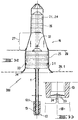
- FIG. 1 shows a device 100 for artificial insemination shown by sows, which consist of a catheter 1 and a inserted into a tube end 1.1 of the catheter, sleeve-shaped Bead 2.1 composed.
- the end 1.1 of the catheter has an outwardly directed conical thickening 4.1 on which the catheter attached bead 2.1 supports.
- a second thickening 4.2 attached, in a roughly one Bead length L corresponding distance A from the first thickening 4.1 is arranged. So that the axial position of the Bead 2.1 against the catheter by the arrangement of the two thickenings 4.1, 4.2 set.
- the beads 2.2, 2.3 and 2.4 on the catheter 1 (cf. figures 2 to 4).
- the catheter 1 Given the high demands on Sterility is the catheter 1 with bead 2.1, 2.2, 2.3.2.4 as Disposable device designed.
- the ridges 2.1, 2.2, 2.3, 2.4 can also be used as interchangeable single-use elements.
- Figure 2 is a similar (reference number 200) device shown, in which the replaceable bead 2.2 several peripheral Has recesses 3.1. Like the top of the Figure shows, the previously compressed bead 2.2 takes a significant increased volume and turns into one Plug 20, which can also be seen in Figure 6.
- FIGS. 3 and 4 Reference numbers 2.3, 2.4
- the extended bead (grafting) rounding 9 or bevels 11 so that the catheter tip can be guided more easily can and the animal is not injured.
- the bead shown in Figure 3 has a single, spiral recess 3.2.
- the bead 2.1, 2.2, 2.3, 2.4 is made of a soft, closed-cell polyethylene or polyurethane with a density of about 40 kg / m 3 , with the aid of plasticizers and other additives the return time of the foam being set so that the plug can be compressed is that the cross section falls below the lumen of the vagina.
- the animal's cervix is reached.
- the end of the expansion time is awaited, the plug expanding so far that the vagina is closed with a soft, retractable plug 20.
- the expansion time can be set according to the temperature of the vagina and the size, according to professional judgment with appropriate foam bodies.
- the hollow body 16 is divided into two chambers, namely in a first, larger chamber 25 for receiving the uncompressed Bead and a second, smaller chamber for receiving of the compressed bead.
- the location of the uncompressed Bead in the first chamber 25 is through the knobs 33 defines that on the inner surface of the cylindrical Part (chamber 25) are arranged and in the peripheral Fit recesses 3.1 of the bead.
- the hollow body 16 is in a transition region 27 gently from the first to the second chamber rejuvenated.
- the transition area 27 there is also one on the jacket of the Hollow body 16 incorporated opening 32 through which a liquid lubricant into the interior of the hollow body a pipette, not shown, is to be introduced.
- the device 300 is made of plastic manufactured washer 28, 28.1 provided that either to the tapered part (transition region 27) of the hollow body 16 or on the collar 34 supports.
- the as a stop element for the insemination appropriately disinfected Washer 28, 28.1 can be used several times.
- the artificial insemination is carried out as follows:
- the pubic area 21 (see FIG. 6) must be cleaned very intensively. Then the bead and the exterior of the hollow body with Paraffin oil treated and made lubricious. Other lubricants are not to be used as they can damage the sperm.
- the device as shown in FIG. 1, with the hollow body 6 inserted into the vagina 31.
- the Hollow body 6 can be inserted into vagina 31 until its outwardly projecting collar 6.1 or annular disk 28, 28.1 (see Fig. 5a) rests on the outer pubic area.
- When moving on the device bumps the thickening 4.1 against one Truncated cone 6.2 of the hollow body 6 and opens its thin-film closures 6.3 and let the bead pass. This will now germ-free down to the cervix.
- the first compressed Bead expands within about 20 seconds, takes its largest volume and closes the vagina in the direction Cervix so that the sperm cannot flow back.
- the catheter 1 instructs one its end opposite the bead 1.2 Return valve 13 on.
- the return valve 13 is in the form an elongated, elastic sleeve 13.1 executed a thin-skinned, membrane-like, also elastic locking element 23 owns. When inserting a sharpened donor element 24 the locking member 23 is pierced. When pulling out the donor element 24 closes the elastic locking member 23 and prevents the sperm from flowing back.
- the Return valve 13 can of course in all described embodiments find use of the device.
- the sow must "hold” the device, i.e. i.e. when withdrawing there must be slight resistance to the bead his.
- the experienced keeper knows up to which Point to guide the catheter unit.
- the End of a seed container 18 (see. Fig. 6) connected.
- the container 18 is ensured that the sperm can flow into the uterus 41.
- the whole The duration of the insemination should last at least 3 minutes.
- the sow is stimulated accordingly during and after insemination.
- the catheter tip After emptying the semen container 18 is the catheter tip not withdraw immediately. This will make unnecessary sperm reflux avoided. If a certain amount of time has expired, the catheter 1 with the bead and at the same time the hollow body 6 with removed.
Abstract
Description
Die Erfindung betrifft eine Vorrichtung zur Besamung von
Tieren, insbesondere Sauen, gemäß dem Oberbegriff von Anspruch 1.The invention relates to a device for insemination of
Animals, in particular sows, according to the preamble of
Eine derartige Vorrichtung ist DE U1 295 05 177.9 des Anmelders zu entnehmen. Der Katheter, der im wesentlichen aus einem relativ steifen Kunststoffrohr besteht, geht an seinem Ende in einen Wulst über, der das Zurückfließen der Samenflüssigkeit bei der Besamung verhindern soll. Ferner ist gemäß vorgenanntem Stand der Technik ein Hohlkörper, vorzugsweise in Form einer Hülse, vorgesehen, der den Wulst und den Katheter umgibt und der bei Einführen des Katheters in die Vagina durchstoßen wird, so daß eine Verbesserung gegenüber infektiöser Kontamination gegeben ist, wie aus der Beschreibung des vorgenannten Standes der Technik hervorgeht.Such a device is DE U1 295 05 177.9 from the applicant refer to. The catheter, which essentially consists of one there is a relatively stiff plastic tube, goes to his End in a bulge that prevents the semen from flowing back should prevent insemination. Furthermore, according to a hollow body, preferably in the form of a sleeve, provided that the bead and the Surrounds the catheter and when the catheter is inserted into the Vagina is pierced, making an improvement over infectious contamination is given, as from the description of the aforementioned prior art.
Es hat sich gezeigt, daß ein mit einem bestimmten Durchmesser versehener Wulst zu Verletzungen der Vagina führen kann, da je nach Lebensalter der Tiere das Lumen der Vagina verschieden weit ist. It has been shown that one with a certain diameter provided bulge can lead to injuries to the vagina because Depending on the age of the animals, the lumen of the vagina varies is far.
Es ist auch schon der Vorschlag gemacht worden, einen Katheter nach Art der sogenannten Ballonkatheter mit einem aufblasbaren Wulst zu versehen, der nach Einführen mit Hilfe einer Luftpumpe oder dergleichen aufgeblasen wird (vgl. DE-AS 1766902). Diese Art eines veränderbaren Wulstes hat jedoch den Nachteil, daß die Handhabung im Tierstall und im Bereich der sich ungebärdig verhaltenden Tiere sehr schwierig ist, so daß eine Anwendung praktisch ausgeschlossen ist.The suggestion has already been made, a catheter in the manner of the so-called balloon catheter with an inflatable Bead to be provided after insertion with the aid of a Air pump or the like is inflated (see. DE-AS 1766902). However, this type of changeable bead has the disadvantage that handling in the animal stable and in the area which is very difficult to behave unruly, so that an application is practically impossible.
Es stellt sich daher die Aufgabe, eine Besamungsvorrichtung anzugeben, die einerseits die Vorteile des Gebrauchsmusters 295 05 177 besitzt, andererseits das Zurückfließen der Samenflüssigkeit weitgehend verhindert, ohne daß eine komplizierte Handhabung erforderlich ist.It is therefore the task of a insemination device specify the one hand the advantages of the utility model 295 05 177 has, on the other hand, the backflow of semen largely prevented without a complicated Handling is required.
Diese Aufgabe wird erfindungsgemäß durch eine Vorrichtung
gemäß Anspruch 1 gelöst.This object is achieved by a device
solved according to
Vorzugsweise ist der Wulst torus- oder zylindrischhülsenförmig ausgebildet und am einzuführenden Ende des Katheters angebracht. Eine zusätzliche Luftführung ist nicht erforderlich. Eine entsprechende Kunststoff-Schaummasse kann so eingestellt werden, daß nach dem Zusammendrücken, was beispielsweise manuell oder aber durch die Außenwandung des Hohlkörpers geschehen kann, eine ausreichende Zeit verbleibt, bis sich der Wulst wieder soweit gedehnt hat, daß er die Innenwandung der Vagina abschließt. Das verwendete Material - Schaumkunststoff - ist so weich, daß es leicht wieder aus der Vagina zurückgezogen werden kann, ohne daß es zu Verletzungen kommt.The bead is preferably toroidal or cylindrical sleeve-shaped trained and at the end of the catheter to be inserted appropriate. An additional air flow is not required. A suitable plastic foam mass can can be set so that after compressing what, for example manually or through the outer wall of the Hollow body can happen, sufficient time remains until the bead has stretched again so far that it has the inner wall which closes the vagina. The material used - Foam plastic - is so soft that it easily comes out of the Vagina can be withdrawn without causing injury comes.
Um den Wulst genau zu plazieren und unverrückbar zu machen, wird vorgeschlagen, daß das Ende des Katheters eine nach außen gerichtete Verdickung aufweist, an der sich der Wulst abstützt. Vorzugsweise kann auch eine zweite Verdickung vorgesehen sein, die in einem, etwa einer Wulstlänge entsprechenden Abstand von der ersten Verdickung angeordnet ist. Die Außendurchmesser der Verdickung sind so bemessen, daß sie das Lumen der Vagina unterschreiten und damit nicht zu Verletzungen führen können.To place the bead precisely and make it immovable, it is suggested that the end of the catheter be an outward has directed thickening on which the bead is supported. A second thickening can preferably also be provided be in a, approximately corresponding to a bead length Distance from the first thickening is arranged. The outside diameter the thickening are such that they are Fall below the lumen of the vagina and therefore not cause injuries being able to lead.
Für das Material des Wulstes eignen sich weichelastische Schaumkunststoffe, die zusammendrückbar sind und sich nach dem Loslassen in einer bestimmten Zeit, beispielsweise innerhalb von 10 bis 30 Sekunden erweitern und wieder dehnen und die ursprüngliche Form wieder annehmen. Beispielsweise haben Schaumkunststoffe aus Polyurethan diese Eigenschaft. Es werden hierzu Weichschaumstoffe gemäß DIN 7726 verwendet, die bei Druckbelastung einen relativ geringen Verformungswiderstand aufweisen. Das langsame Retardieren kann mit Hilfe von Weichmachern und dem Fachmann bekannten Rezepturen eingestellt werden.Soft elastic are suitable for the material of the bead Foam plastics that are compressible and that releasing in a certain time, for example within expand from 10 to 30 seconds and stretch again and return to the original form. For example Foam plastics made of polyurethane have this property. It will soft foams according to DIN 7726 are used for this a relatively low resistance to deformation when subjected to pressure exhibit. Slow retardation can be done with the help of Plasticizers and recipes known to those skilled in the art become.
Das Zusammendrücken und Aufrechterhalten des komprimierten Wulstes vor der eigentlichen Besamung kann in unterschiedlicher Weise erreicht werden. Beispielsweise kann eine abreißbare Folienhülse verwendet werden. Der freigegebene Wulst erweitert sich zu seiner ursprünglichen Form, wobei innerhalb einer bestimmten Zeit, die ausreicht, daß die Katheterspitze den Muttermund erreicht, die Form wieder angenommen wird.Squeezing and maintaining the compressed Bead before the actual insemination can be in different Way to be achieved. For example, a tearable Foil sleeve can be used. The released bead expands to its original form, being inside a certain time that is sufficient for the catheter tip reached the cervix, the shape is restored.
Der Wulst kann entsprechend den Bedürfnissen und unter Berücksichtigung von Herstellungskosten an seiner Außenseite glatt-zylindrisch sein; es ist aber auch möglich, ihn in Form einer Spirale oder mit lamellenartigen Unterbrechungen zu versehen, so daß er an seiner Außenseite einer ring- oder spiralförmige, periphere Ausnehmung aufweist.The bead can be made according to needs and taking into account of manufacturing costs on its outside be smooth-cylindrical; but it is also possible to shape it a spiral or with lamellar interruptions provided so that it is a ring or Has spiral, peripheral recess.
Um das Zurückfließen der Samenflüssigkeit zu verhindern, ist am Katheter eine Knickstelle oder ein Rücklaufventil vorgesehen, das an seinem dem Wulst gegenüberliegenden Ende angeordnet ist.To prevent the semen from flowing back a kink or a return valve is provided on the catheter, arranged at its end opposite the bead is.
Darauf hinzuweisen ist, daß der vor Beginn der Besamung den Wulst umgebende, vor infektiöser Kontamination schützender Hohlkörper nach der Einführung am Beginn der Vagina verbleibt, während das mit dem Wulst versehene Ende des Katheters in Richtung Gebärmutter verschiebbar ist und aus dem Hohlkörper ausschiebbar ist.It should be noted that before the insemination the Bead surrounding, protecting against infectious contamination Hollow body remains at the beginning of the vagina after insertion, during the beaded end of the catheter is displaceable towards the uterus and out of the Hollow body can be pushed out.
Der Hohlkörper kann "zweistufig" ausgebildet, d.h. in zwei Kammern unterteilt sein, von denen eine erste Kammer zur Aufnahme des nicht komprimierten Wulstes dient. Bei Lagerung wird der erweiterte Wulst nicht zusammengedrückt und vor Beschädigungen geschützt. Die kleinere, zweite Kammer dient wiederum zur Aufnahme des zusammengedrückten Wulstes.The hollow body can be "two-stage", i.e. in two Be divided into chambers, of which a first chamber for receiving of the non-compressed bead. When storing the expanded bead is not pressed together and is damaged protected. The smaller, second chamber serves again to take up the compressed bead.
Weitere Merkmale und Vorteile der Erfindung gehen aus den Ausführungsbeispielen hervor, die anhand der Zeichnung näher erläutert werden. Die Figuren der Zeichnung zeigen im einzelnen:
Figur 1- einen axialen Halbschnitt der Vorrichtung, mit einem in den Hohlkörper eingeschobenen Wulst,
- Figur 2
- eine Besamung-Vorrichtung mit einem die peripheren Ausnehmungen aufweisenden Wulst, der komprimiert und freigegeben gezeigt ist,
- Figuren 3 und 4
- weitere Ausführungsformen des Wulstes,
- Figur 5a
- eine andere Ausführungsform der Vorrichtung, im axialen Schnitt,
- Figur 5b
- ein vergrößertes Detail eines Rücklaufventils, und
Figur 6- eine künstliche Besamung einer Sau unter Verwendung der erfindungsgemäßen Vorrichtung
- Figure 1
- an axial half-section of the device, with a bead inserted into the hollow body,
- Figure 2
- an insemination device with a bead having the peripheral recesses, which is shown compressed and released,
- Figures 3 and 4
- further embodiments of the bead,
- Figure 5a
- another embodiment of the device, in axial section,
- Figure 5b
- an enlarged detail of a return valve, and
- Figure 6
- artificial insemination of a sow using the device according to the invention
In Figur 1 ist eine Vorrichtung 100 zur künstlichen Besamung
von Sauen dargestellt, die sich aus einem Katheter 1 und einem
an ein Rohrende 1.1 des Katheters eingesetzten, hülsenförmigen
Wulst 2.1 zusammensetzt.1 shows a
Das Ende 1.1 des Katheters weist eine nach außen gerichtete,
kegelförmige Verdickung 4.1 auf, an der sich der an dem Katheter
aufgesetzte Wulst 2.1 abstützt. Am Katheter 1 ist noch
eine zweite Verdickung 4.2 angebracht, die in einem etwa einer
Wulstlänge L entsprechenden Abstand A von der ersten Verdickung
4.1 angeordnet ist. Damit ist die axiale Lage des
Wulstes 2.1 gegenüber dem Katheter durch die Anordnung der
beiden Verdickungen 4.1, 4.2 festgelegt. In gleicher Weise
sind am Katheter 1 die Wülste 2.2, 2.3 und 2.4 (vgl. Figuren
2 bis 4) aufgesetzt. Angesicht der hohen Anforderungen an
Sterilität ist der Katheter 1 mit Wulst 2.1, 2.2, 2.3,2.4 als
Einweg-Vorrichtung konzipiert. Die Wülste 2.1, 2.2, 2.3, 2.4
können auch als auswechselbare Einweg-Elemente verwendet werden.The end 1.1 of the catheter has an outwardly directed
conical thickening 4.1 on which the catheter
attached bead 2.1 supports. At
In Figur 2 ist eine ähnliche (Bezugszahl 200) Vorrichtung
dargestellt, bei der der auswechselbare Wulst 2.2 mehrere peripheren
Ausnehmungen 3.1 aufweist. Wie das obere Teil der
Figur zeigt, nimmt der vorher komprimierte Wulst 2.2 ein wesentlich
vergrößertes Volumen an und verwandelt sich in einen
Pfropfen 20, der auch in Figur 6 zu sehen ist.In Figure 2 is a similar (reference number 200) device
shown, in which the replaceable bead 2.2 several peripheral
Has recesses 3.1. Like the top of the
Figure shows, the previously compressed bead 2.2 takes a significant
increased volume and turns into one
Ferner sind in den Figuren 3 und 4 andere Ausführungsformen
(Bezugszahlen 2.3, 2.4) des Wulstes gezeigt, bei denen der
erweiterte Wulst (Pfropfen) Abrundungen 9 oder Abschrägungen
11 aufweist, damit die Katheterspitze leichter geführt werden
kann und das Tier nicht verletzt wird.Furthermore, other embodiments are shown in FIGS. 3 and 4
(Reference numbers 2.3, 2.4) of the bead shown, in which the
extended bead (grafting) rounding 9 or
Der in Fig.3 gezeigte Wulst besitzt eine einzige, spiralförmige
Ausnehmung 3.2. Der Wulst 2.1, 2.2, 2.3, 2.4 ist aus
einem weichen, geschlossenzelligen Polyethylen oder Polyurethan
einer Dichte etwa von 40 kg/m3 angefertigt, wobei mit
Hilfe von Weichmachern und anderen Additiven die Rückstellzeit
des Schaumstoffes so eingestellt ist, daß der Pfropfen
so zusammendrückbar ist, daß der Querschnitt das Lumen der
Vagina unterschreitet. Zunächst wird der Muttermund des Tieres
erreicht. Innerhalb der Endposition wird das Ende der Expansionszeit
abgewartet, wobei der Pfropfen sich soweit ausdehnt,
daß die Vagina mit einem weichen, zurückziehbaren
Pfropfen 20 verschlossen ist. Die Einstellung der Expansionzeit
entsprechend der Temperatur der Vagina und der Größe,
kann nach fachmännischem Ermessen mit entsprechenden Schaumstoffkörpern
erfolgen. The bead shown in Figure 3 has a single, spiral recess 3.2. The bead 2.1, 2.2, 2.3, 2.4 is made of a soft, closed-cell polyethylene or polyurethane with a density of about 40 kg / m 3 , with the aid of plasticizers and other additives the return time of the foam being set so that the plug can be compressed is that the cross section falls below the lumen of the vagina. First, the animal's cervix is reached. Within the end position, the end of the expansion time is awaited, the plug expanding so far that the vagina is closed with a soft,
Bei einer anderen Ausführungsform (Bezugszahl 300; vgl.Fig.
5a) ist der Hohlkörper 16 in zwei Kammern aufgeteilt, nämlich
in eine erste, größere Kammer 25 zur Aufnahme des nicht komprimierten
Wulstes und eine zweite, kleinere Kammer zur Aufnahme
des zusammengedrückten Wulstes. Die Lage des nicht komprimierten
Wulstes in der ersten Kammer 25 ist durch die Noppen
33 definiert, die an der inneren Oberfläche des zylindrischen
Teils (Kammer 25) angeordnet sind und die in die peripheren
Ausnehmungen 3.1 des Wulstes hineinpassen.In another embodiment (
Wie die Figur zeigt, ist der Hohlkörper 16 in einem Übergangsbereich
27 von der ersten in die zweite Kammer sanft
verjüngt. Im Ubergangsbereich 27 ist auch eine am Mantel des
Hohlkörpers 16 eingearbeitete Öffnung 32 zu sehen, durch die
ein flüssiges Gleitmittel in das Innere des Hohlkörpers mittels
einer nicht dargestellten Pipette einzuführen ist.As the figure shows, the
Weiterhin ist bei der Vorrichtung 300 eine aus Kunststoff
hergestellte Ringscheibe 28, 28.1 vorgesehen, die sich entweder
an das verjüngte Teil (Übergangsbereich 27) des Hohlkörpers
16 oder an dessen Kragen 34 stützt. Die als Anschlagelement
bei der Besamung dienende, entsprechend desinfizierte
Ringscheibe 28, 28.1 kann mehrfach verwendet werden.Furthermore, the
Ist der günstigste Zeitpunkt für die Belegung festgelegt, wird die künstliche Besamung wie folgt durchgeführt:Once the best time for occupancy has been determined, the artificial insemination is carried out as follows:
Zuerst ist die Scham 21 (vgl. Fig. 6) sehr intensiv zu reinigen. Danach wird der Wulst und das Äußere des Hohlkörpers mit Parafinöl behandelt und gleitfähig gemacht. Andere Gleitmittel sind nicht zu verwenden, da sie das Sperma schädigen können.First of all, the pubic area 21 (see FIG. 6) must be cleaned very intensively. Then the bead and the exterior of the hollow body with Paraffin oil treated and made lubricious. Other lubricants are not to be used as they can damage the sperm.
Danach wird die Vorrichtung, wie sie die Fig. 1 zeigt, mit
dem Hohlkörper 6 voran in die Scheide 31 eingeführt. Der
Hohlkörper 6 ist so weit in die Scheide 31 einführbar, bis
sein nach außen ragender Kragen 6.1 bzw. Ringscheibe 28, 28.1
(vgl. Fig. 5a) auf der äußeren Scham aufliegt. Beim Weiterschieben
der Vorrichtung stößt die Verdickung 4.1 gegen einen
Kegelstumpf 6.2 des Hohlkörpers 6 und öffnet seine Dünnfilmverschlüsse
6.3 und läßt den Wulst passieren. Dieser wird nun
keimarm bis hin zum Muttermund geführt. Der zunächst komprimierte
Wulst erweitert sich innerhalb etwa 20 Sekunden, nimmt
sein größtes Volumen an und verschließt die Vagina in Richtung
Muttermund, so daß das Sperma zurück nicht fließen kann.Then the device, as shown in FIG. 1, with
the
Um das Zurückfließen des Sperma durch den Katheter 1 zu verhindern,
ist es vorgesehen, an seinem dem Wulst gegenüberliegenden
Ende 1.2 eine Knickstelle 12 einzubringen. Durch das
einfache Knicken des Katheters 1 und Einklemmen mit einer
Klammer, Clipverschluß oder dgl. wird erreicht, daß dieser
unmittelbar nach der Besamung verschlossen bleibt.To prevent the sperm from flowing back through the
Bei einer anderen Ausführungsform weist der Katheter 1 ein an
seinem dem Wulst gegenüberliegenden Ende 1.2 aufgesetztes
Rücklaufventil 13 auf. Das Rücklaufventil 13 ist in der Form
einer länglichen, elastischen Hülse 13.1 ausgeführt, die ein
dünnhäutiges, membranartiges, ebenso elastisches Sperrorgan
23 besitzt. Beim Einführen eines angespitzten Spenderelementes
24 wird das Sperrorgan 23 durchstoßen. Beim Herausziehen
des Spenderelementes 24 verschließt das elastische Sperrorgan
23 und verhindert das Zurückfließen der Samenflüssigkeit. Das
Rücklaufventil 13 kann natürlich bei allen beschriebenen Ausführungsformen
der Vorrichtung Verwendung finden.In another embodiment, the
Die Sau muß die Vorrichtung dabei "halten", d. h., beim Zurückziehen
des Wulstes muß ein leichter Widerstand festzustellen
sein. Der erfahrene Halter weiß dabei, bis zu welchem
Punkt die Kathetereinheit zu führen hat. Danach wird an das
Ende ein Samenbehälter 18 (vgl. Fig. 6) angeschlossen. Durch
leichten Druck auf den Behälter 18 wird dafür gesorgt, daß
das Sperma in die Gebärmutter 41 fließen kann. Die gesamte
Zeit der Besamungsdauer sollte mindestens 3 Minuten dauern.
Die Sau wird während und nach der Besamung entsprechend stimuliert.The sow must "hold" the device, i.e. i.e. when withdrawing
there must be slight resistance to the bead
his. The experienced keeper knows up to which
Point to guide the catheter unit. After that, the
End of a seed container 18 (see. Fig. 6) connected. By
slight pressure on the
Nach der Leerung des Samenbehälters 18 ist die Katheterspitze
nicht sofort zurückzuziehen. So wird unnötiger Spermarückfluß
vermieden. Ist eine gewisse Zeit abgelaufen, werden der Katheter
1 mit dem Wulst und zugleich der Hohlkörper 6 mit entfernt.After emptying the
Claims (15)
- A device (100; 200; 300) for inseminating animals, particularly sows, comprising a catheter suitable for conveying the seminal fluid and for insertion into the vagina, the catheter having a bead (2.1, 2.2, 2.3, 2.4) at its insertion end (1.1) and a sleeve-like hollow member (6; 16) insertable into the beginning of the vagina, so as to slide the bead and catheter into the vagina, wherein the bead (2.1, 2.2, 2.3, 2.4) is made of a foam plastic and, before insertion into the body cavity, can be compressed to a cross-section less than the lumen of the body cavity, characterised in that the foam plastic is adjusted by plasticisers and additives so that when it reaches an end position corresponding to the vaginal orifice of the animal, after an expansion time adjustable to the size and temperature of the vagina it expands until the body cavity is closed by a soft, withdrawable plug (20).
- A device according to claim 1, characterised in that the catheter (1) at its end region (1.1) has an outwardly directed thick part (4.1) at which the bead (2.1, 2.2, 2.3, 2.4) abuts.
- A device according to claim 2, characterised in that the catheter has a second thick part (4.2) disposed at a distance (A) from the first thick part (4.1) approximately equal to the length of the bead (L), so that the axial position of the bead (2.1, 2.2, 2.3) relative to the catheter is determined by the position of the two thick parts (4.1, 4.2).
- A device according to claim 2 or 3, characterised in that the first thick part (4.1) at the end (1.1) of the catheter is frusto-conical.
- A device according to claims 1 to 4, characterised in that the bead (2.1, 2.2, 2.3, 2.4) is interchangeable.
- A device according to claims 1 to 5, characterised in that the bead (2.1, 2.2, 2.3, 2.4) is toroidal or sleeve-shaped.
- A device according to at least one of the preceding claims, characterised in that the bead (2.1, 2.2, 2.3, 2.4) is made of soft, preferably closed-cell polyurethane-based foam plastic.
- A device according to at least one of the preceding claims, characterised in that the bead (2.2, 2.3, 2.4) on its outside has at least one annular or spiral peripheral recess (3.1, 3.2).
- A device according to at least one of the preceding claims, characterised in that at its end opposite the bead (2.1, 2.2, 2.3, 2.4) the catheter (1) has a set breaking or bending place (12).
- A device according to at least one of the preceding claims, characterised in that a non-return valve (13) adjoins the end of the catheter (1) opposite the bead (2.1, 2.2, 2.3, 2.4).
- A device according to claim 10, characterised in that the non-return valve (13) comprises an elastic diaphragm-like blocking means (23) which can be perforated by a syringe or a conical dispensing element (24) and closed after the dispensing element (24) has been withdrawn.
- A device according to at least one of the preceding claims, characterised in that the sleeve-like hollow member (16) is divided into two chambers (25, 26), i.e. into a first chamber (25) for holding the sleeve (2.1, 2.2, 2.3, 2.4) before compression and a second chamber (26) for holding the sleeve (2.1, 2.2, 2.3, 2.4) when compressed.
- A device according to at least one of the preceding claims, characterised in that the hollow member (6; 16) surrounding the sleeve (2.1, 2.2, 2.3, 2.4) before the beginning of insemination and protecting it from infectious contamination remains at the beginning of the vagina after insertion, whereas the beaded end (1.1) of the catheter (1) is movable towards the uterus and can be pushed out of the hollow member (6; 16).
- A device according to at least one of the preceding claims, characterised in that a stop element in the form of an annular plate (28, 28.1) is mounted on the hollow member (6; 16).
- A device according to claim 14, characterised in that the annular plate (28, 28.1) is interchangeable.
Priority Applications (1)
| Application Number | Priority Date | Filing Date | Title |
|---|---|---|---|
| DE29924595U DE29924595U1 (en) | 1998-08-04 | 1999-07-17 | Injector pump for artificial insemination of sow has back-flow prevention valve within delivery catheter wide section |
Applications Claiming Priority (3)
| Application Number | Priority Date | Filing Date | Title |
|---|---|---|---|
| DE29813921U DE29813921U1 (en) | 1998-08-04 | 1998-08-04 | Device for inseminating animals, especially sows |
| DE29813921U | 1998-08-04 | ||
| PCT/EP1999/005112 WO2000007519A1 (en) | 1998-08-04 | 1999-07-17 | Device for inseminating animals, mainly sows |
Publications (2)
| Publication Number | Publication Date |
|---|---|
| EP1100400A1 EP1100400A1 (en) | 2001-05-23 |
| EP1100400B1 true EP1100400B1 (en) | 2004-05-19 |
Family
ID=8060825
Family Applications (1)
| Application Number | Title | Priority Date | Filing Date |
|---|---|---|---|
| EP99936562A Expired - Lifetime EP1100400B1 (en) | 1998-08-04 | 1999-07-17 | Device for inseminating animals, mainly sows |
Country Status (7)
| Country | Link |
|---|---|
| EP (1) | EP1100400B1 (en) |
| AT (1) | ATE266981T1 (en) |
| AU (1) | AU5161099A (en) |
| DE (2) | DE29813921U1 (en) |
| DK (1) | DK1100400T3 (en) |
| ES (1) | ES2222034T3 (en) |
| WO (1) | WO2000007519A1 (en) |
Cited By (15)
| Publication number | Priority date | Publication date | Assignee | Title |
|---|---|---|---|---|
| DE102005051008A1 (en) * | 2005-10-25 | 2007-04-26 | Chen, Sheng-Jui, Pyng-Jenn | Artificial insemination device for animal, has extension member tucked into nozzle via front passage opening of nozzle and amassed in compressed state between forward portion of center orifice and nozzle passage |
| DE102005051007A1 (en) * | 2005-10-25 | 2007-04-26 | Chen, Sheng-Jui, Pyng-Jenn | Artificial insemination device for e.g. pig, has flexible tube that unfolds outward, extends to uterus or its vicinity along cervical tract, and deposits semen into uterus, when semen is squeezed in from rear end of inner catheter |
| US7713687B2 (en) | 2000-11-29 | 2010-05-11 | Xy, Inc. | System to separate frozen-thawed spermatozoa into x-chromosome bearing and y-chromosome bearing populations |
| US7723116B2 (en) | 2003-05-15 | 2010-05-25 | Xy, Inc. | Apparatus, methods and processes for sorting particles and for providing sex-sorted animal sperm |
| US7758811B2 (en) | 2003-03-28 | 2010-07-20 | Inguran, Llc | System for analyzing particles using multiple flow cytometry units |
| US7820425B2 (en) | 1999-11-24 | 2010-10-26 | Xy, Llc | Method of cryopreserving selected sperm cells |
| US7833147B2 (en) | 2004-07-22 | 2010-11-16 | Inguran, LLC. | Process for enriching a population of sperm cells |
| US7838210B2 (en) | 2004-03-29 | 2010-11-23 | Inguran, LLC. | Sperm suspensions for sorting into X or Y chromosome-bearing enriched populations |
| US7855078B2 (en) | 2002-08-15 | 2010-12-21 | Xy, Llc | High resolution flow cytometer |
| US7929137B2 (en) | 1997-01-31 | 2011-04-19 | Xy, Llc | Optical apparatus |
| US8137967B2 (en) | 2000-11-29 | 2012-03-20 | Xy, Llc | In-vitro fertilization systems with spermatozoa separated into X-chromosome and Y-chromosome bearing populations |
| US8486618B2 (en) | 2002-08-01 | 2013-07-16 | Xy, Llc | Heterogeneous inseminate system |
| US8497063B2 (en) | 2002-08-01 | 2013-07-30 | Xy, Llc | Sex selected equine embryo production system |
| US9365822B2 (en) | 1997-12-31 | 2016-06-14 | Xy, Llc | System and method for sorting cells |
| US11230695B2 (en) | 2002-09-13 | 2022-01-25 | Xy, Llc | Sperm cell processing and preservation systems |
Families Citing this family (1)
| Publication number | Priority date | Publication date | Assignee | Title |
|---|---|---|---|---|
| CZ2008431A3 (en) * | 2008-07-10 | 2010-01-20 | Univerzita Tomáše Bati ve Zlíne | Catheter for intracervical insemination |
Family Cites Families (4)
| Publication number | Priority date | Publication date | Assignee | Title |
|---|---|---|---|---|
| US3543758A (en) | 1967-08-14 | 1970-12-01 | Kendall & Co | Catheter with safety indicator |
| DE2701998A1 (en) * | 1977-01-19 | 1978-07-20 | Mile Jovanov | Cow artificial insemination equipment - comprises measured tube with anchoring devices at cervical end |
| DE29505177U1 (en) | 1995-03-27 | 1995-05-18 | Kisfeld Alfons | Device for the artificial fertilization of animals, in particular sows |
| FR2762506B1 (en) * | 1997-04-25 | 1999-11-05 | Genes Diffusion | ARTIFICIAL INSEMINATION DEVICE FOR LIVESTOCK ANIMALS SUCH AS, IN PARTICULAR, SOWS |
-
1998
- 1998-08-04 DE DE29813921U patent/DE29813921U1/en not_active Expired - Lifetime
-
1999
- 1999-07-17 AT AT99936562T patent/ATE266981T1/en not_active IP Right Cessation
- 1999-07-17 DK DK99936562T patent/DK1100400T3/en active
- 1999-07-17 ES ES99936562T patent/ES2222034T3/en not_active Expired - Lifetime
- 1999-07-17 DE DE59909533T patent/DE59909533D1/en not_active Expired - Lifetime
- 1999-07-17 AU AU51610/99A patent/AU5161099A/en not_active Abandoned
- 1999-07-17 EP EP99936562A patent/EP1100400B1/en not_active Expired - Lifetime
- 1999-07-17 WO PCT/EP1999/005112 patent/WO2000007519A1/en active IP Right Grant
Cited By (32)
| Publication number | Priority date | Publication date | Assignee | Title |
|---|---|---|---|---|
| US7929137B2 (en) | 1997-01-31 | 2011-04-19 | Xy, Llc | Optical apparatus |
| US9422523B2 (en) | 1997-12-31 | 2016-08-23 | Xy, Llc | System and method for sorting cells |
| US9365822B2 (en) | 1997-12-31 | 2016-06-14 | Xy, Llc | System and method for sorting cells |
| US7820425B2 (en) | 1999-11-24 | 2010-10-26 | Xy, Llc | Method of cryopreserving selected sperm cells |
| US8652769B2 (en) | 2000-11-29 | 2014-02-18 | Xy, Llc | Methods for separating frozen-thawed spermatozoa into X-chromosome bearing and Y-chromosome bearing populations |
| US7771921B2 (en) | 2000-11-29 | 2010-08-10 | Xy, Llc | Separation systems of frozen-thawed spermatozoa into X-chromosome bearing and Y-chromosome bearing populations |
| US9879221B2 (en) | 2000-11-29 | 2018-01-30 | Xy, Llc | Method of in-vitro fertilization with spermatozoa separated into X-chromosome and Y-chromosome bearing populations |
| US7713687B2 (en) | 2000-11-29 | 2010-05-11 | Xy, Inc. | System to separate frozen-thawed spermatozoa into x-chromosome bearing and y-chromosome bearing populations |
| US8137967B2 (en) | 2000-11-29 | 2012-03-20 | Xy, Llc | In-vitro fertilization systems with spermatozoa separated into X-chromosome and Y-chromosome bearing populations |
| US8497063B2 (en) | 2002-08-01 | 2013-07-30 | Xy, Llc | Sex selected equine embryo production system |
| US8486618B2 (en) | 2002-08-01 | 2013-07-16 | Xy, Llc | Heterogeneous inseminate system |
| US7855078B2 (en) | 2002-08-15 | 2010-12-21 | Xy, Llc | High resolution flow cytometer |
| US11230695B2 (en) | 2002-09-13 | 2022-01-25 | Xy, Llc | Sperm cell processing and preservation systems |
| US11261424B2 (en) | 2002-09-13 | 2022-03-01 | Xy, Llc | Sperm cell processing systems |
| US9377390B2 (en) | 2003-03-28 | 2016-06-28 | Inguran, Llc | Apparatus, methods and processes for sorting particles and for providing sex-sorted animal sperm |
| US10100278B2 (en) | 2003-03-28 | 2018-10-16 | Inguran, Llc | Multi-channel system and methods for sorting particles |
| US11718826B2 (en) | 2003-03-28 | 2023-08-08 | Inguran, Llc | System and method for sorting particles |
| US11104880B2 (en) | 2003-03-28 | 2021-08-31 | Inguran, Llc | Photo-damage system for sorting particles |
| US8664006B2 (en) | 2003-03-28 | 2014-03-04 | Inguran, Llc | Flow cytometer apparatus and method |
| US8709817B2 (en) | 2003-03-28 | 2014-04-29 | Inguran, Llc | Systems and methods for sorting particles |
| US8709825B2 (en) | 2003-03-28 | 2014-04-29 | Inguran, Llc | Flow cytometer method and apparatus |
| US8748183B2 (en) | 2003-03-28 | 2014-06-10 | Inguran, Llc | Method and apparatus for calibrating a flow cytometer |
| US9040304B2 (en) | 2003-03-28 | 2015-05-26 | Inguran, Llc | Multi-channel system and methods for sorting particles |
| US7943384B2 (en) | 2003-03-28 | 2011-05-17 | Inguran Llc | Apparatus and methods for sorting particles |
| US7758811B2 (en) | 2003-03-28 | 2010-07-20 | Inguran, Llc | System for analyzing particles using multiple flow cytometry units |
| US7799569B2 (en) | 2003-03-28 | 2010-09-21 | Inguran, Llc | Process for evaluating staining conditions of cells for sorting |
| US7723116B2 (en) | 2003-05-15 | 2010-05-25 | Xy, Inc. | Apparatus, methods and processes for sorting particles and for providing sex-sorted animal sperm |
| US7838210B2 (en) | 2004-03-29 | 2010-11-23 | Inguran, LLC. | Sperm suspensions for sorting into X or Y chromosome-bearing enriched populations |
| US7892725B2 (en) | 2004-03-29 | 2011-02-22 | Inguran, Llc | Process for storing a sperm dispersion |
| US7833147B2 (en) | 2004-07-22 | 2010-11-16 | Inguran, LLC. | Process for enriching a population of sperm cells |
| DE102005051008A1 (en) * | 2005-10-25 | 2007-04-26 | Chen, Sheng-Jui, Pyng-Jenn | Artificial insemination device for animal, has extension member tucked into nozzle via front passage opening of nozzle and amassed in compressed state between forward portion of center orifice and nozzle passage |
| DE102005051007A1 (en) * | 2005-10-25 | 2007-04-26 | Chen, Sheng-Jui, Pyng-Jenn | Artificial insemination device for e.g. pig, has flexible tube that unfolds outward, extends to uterus or its vicinity along cervical tract, and deposits semen into uterus, when semen is squeezed in from rear end of inner catheter |
Also Published As
| Publication number | Publication date |
|---|---|
| AU5161099A (en) | 2000-02-28 |
| DE59909533D1 (en) | 2004-06-24 |
| WO2000007519A1 (en) | 2000-02-17 |
| ATE266981T1 (en) | 2004-06-15 |
| DK1100400T3 (en) | 2004-09-06 |
| EP1100400A1 (en) | 2001-05-23 |
| DE29813921U1 (en) | 1998-10-08 |
| ES2222034T3 (en) | 2005-01-16 |
Similar Documents
| Publication | Publication Date | Title |
|---|---|---|
| EP1100400B1 (en) | Device for inseminating animals, mainly sows | |
| DE2513241C3 (en) | Device for inserting an intrauterine insert | |
| EP0242711B1 (en) | Catheter for artificial insemination | |
| DE60014440T2 (en) | DEVICE FOR THE ARTIFICIAL FERTILIZATION OF PIGS | |
| EP0301292B1 (en) | Closure for a male urethra | |
| EP0442072B1 (en) | Connector for medical conduits | |
| EP0593948B1 (en) | Stent-set | |
| DD290810A5 (en) | DISPOSABLE SYRINGE | |
| DE3590580C1 (en) | Intravaginal device esp. for contraception | |
| DE1257360B (en) | catheter | |
| DE3107392A1 (en) | Medical instrument | |
| DE2411242B2 (en) | Instrument for introducing substances into the EU sewer channels | |
| DE3444807A1 (en) | CATHETER | |
| DE3211576C2 (en) | Device for drainage of the urinary bladder | |
| DE3803727C1 (en) | Dilator for the postoperative treatment of a body cavity | |
| EP0739612B1 (en) | Device for the artificial insemination of sows | |
| EP0934756A2 (en) | Capillary drainage tube system | |
| DE2701998A1 (en) | Cow artificial insemination equipment - comprises measured tube with anchoring devices at cervical end | |
| EP0195080B1 (en) | Device for introducing a diaphragm | |
| DE3700239C2 (en) | ||
| WO2007080095A1 (en) | Catheter device | |
| DE29924595U1 (en) | Injector pump for artificial insemination of sow has back-flow prevention valve within delivery catheter wide section | |
| DE2818119A1 (en) | Bladder catheter - with double-walled end inflatable to funnel after insertion | |
| EP0821919A2 (en) | Closure for urethra | |
| EP2589349B1 (en) | Medical device for inserting endoscopic instruments into a bodily cavity |
Legal Events
| Date | Code | Title | Description |
|---|---|---|---|
| PUAI | Public reference made under article 153(3) epc to a published international application that has entered the european phase |
Free format text: ORIGINAL CODE: 0009012 |
|
| 17P | Request for examination filed |
Effective date: 20010216 |
|
| AK | Designated contracting states |
Kind code of ref document: A1 Designated state(s): AT BE CH CY DE DK ES FI FR GB GR IE IT LI LU MC NL PT SE |
|
| AX | Request for extension of the european patent |
Free format text: AL;LT;LV;MK;RO;SI |
|
| 17Q | First examination report despatched |
Effective date: 20030314 |
|
| GRAP | Despatch of communication of intention to grant a patent |
Free format text: ORIGINAL CODE: EPIDOSNIGR1 |
|
| GRAS | Grant fee paid |
Free format text: ORIGINAL CODE: EPIDOSNIGR3 |
|
| GRAA | (expected) grant |
Free format text: ORIGINAL CODE: 0009210 |
|
| AK | Designated contracting states |
Kind code of ref document: B1 Designated state(s): AT BE CH CY DE DK ES FI FR GB GR IE IT LI LU MC NL PT SE |
|
| PG25 | Lapsed in a contracting state [announced via postgrant information from national office to epo] |
Ref country code: IT Free format text: LAPSE BECAUSE OF FAILURE TO SUBMIT A TRANSLATION OF THE DESCRIPTION OR TO PAY THE FEE WITHIN THE PRESCRIBED TIME-LIMIT;WARNING: LAPSES OF ITALIAN PATENTS WITH EFFECTIVE DATE BEFORE 2007 MAY HAVE OCCURRED AT ANY TIME BEFORE 2007. THE CORRECT EFFECTIVE DATE MAY BE DIFFERENT FROM THE ONE RECORDED. Effective date: 20040519 Ref country code: IE Free format text: LAPSE BECAUSE OF FAILURE TO SUBMIT A TRANSLATION OF THE DESCRIPTION OR TO PAY THE FEE WITHIN THE PRESCRIBED TIME-LIMIT Effective date: 20040519 Ref country code: FI Free format text: LAPSE BECAUSE OF FAILURE TO SUBMIT A TRANSLATION OF THE DESCRIPTION OR TO PAY THE FEE WITHIN THE PRESCRIBED TIME-LIMIT Effective date: 20040519 Ref country code: CY Free format text: LAPSE BECAUSE OF FAILURE TO SUBMIT A TRANSLATION OF THE DESCRIPTION OR TO PAY THE FEE WITHIN THE PRESCRIBED TIME-LIMIT Effective date: 20040519 |
|
| REG | Reference to a national code |
Ref country code: GB Ref legal event code: FG4D Free format text: NOT ENGLISH |
|
| REG | Reference to a national code |
Ref country code: CH Ref legal event code: EP |
|
| REG | Reference to a national code |
Ref country code: IE Ref legal event code: FG4D Free format text: GERMAN |
|
| REF | Corresponds to: |
Ref document number: 59909533 Country of ref document: DE Date of ref document: 20040624 Kind code of ref document: P |
|
| PG25 | Lapsed in a contracting state [announced via postgrant information from national office to epo] |
Ref country code: LU Free format text: LAPSE BECAUSE OF NON-PAYMENT OF DUE FEES Effective date: 20040717 Ref country code: AT Free format text: LAPSE BECAUSE OF NON-PAYMENT OF DUE FEES Effective date: 20040717 |
|
| PG25 | Lapsed in a contracting state [announced via postgrant information from national office to epo] |
Ref country code: MC Free format text: LAPSE BECAUSE OF NON-PAYMENT OF DUE FEES Effective date: 20040731 Ref country code: LI Free format text: LAPSE BECAUSE OF NON-PAYMENT OF DUE FEES Effective date: 20040731 Ref country code: CH Free format text: LAPSE BECAUSE OF NON-PAYMENT OF DUE FEES Effective date: 20040731 Ref country code: BE Free format text: LAPSE BECAUSE OF NON-PAYMENT OF DUE FEES Effective date: 20040731 |
|
| PG25 | Lapsed in a contracting state [announced via postgrant information from national office to epo] |
Ref country code: SE Free format text: LAPSE BECAUSE OF FAILURE TO SUBMIT A TRANSLATION OF THE DESCRIPTION OR TO PAY THE FEE WITHIN THE PRESCRIBED TIME-LIMIT Effective date: 20040819 Ref country code: GR Free format text: LAPSE BECAUSE OF FAILURE TO SUBMIT A TRANSLATION OF THE DESCRIPTION OR TO PAY THE FEE WITHIN THE PRESCRIBED TIME-LIMIT Effective date: 20040819 |
|
| REG | Reference to a national code |
Ref country code: DK Ref legal event code: T3 |
|
| GBT | Gb: translation of ep patent filed (gb section 77(6)(a)/1977) |
Effective date: 20040818 |
|
| LTIE | Lt: invalidation of european patent or patent extension |
Effective date: 20040519 |
|
| REG | Reference to a national code |
Ref country code: IE Ref legal event code: FD4D |
|
| REG | Reference to a national code |
Ref country code: ES Ref legal event code: FG2A Ref document number: 2222034 Country of ref document: ES Kind code of ref document: T3 |
|
| BERE | Be: lapsed |
Owner name: KISFELD, ALFONS Effective date: 20040731 |
|
| ET | Fr: translation filed | ||
| REG | Reference to a national code |
Ref country code: CH Ref legal event code: PL |
|
| PLBE | No opposition filed within time limit |
Free format text: ORIGINAL CODE: 0009261 |
|
| STAA | Information on the status of an ep patent application or granted ep patent |
Free format text: STATUS: NO OPPOSITION FILED WITHIN TIME LIMIT |
|
| 26N | No opposition filed |
Effective date: 20050222 |
|
| BERE | Be: lapsed |
Owner name: *KISFELD ALFONS Effective date: 20040731 |
|
| PG25 | Lapsed in a contracting state [announced via postgrant information from national office to epo] |
Ref country code: PT Free format text: LAPSE BECAUSE OF NON-PAYMENT OF DUE FEES Effective date: 20041019 |
|
| PGFP | Annual fee paid to national office [announced via postgrant information from national office to epo] |
Ref country code: DK Payment date: 20130719 Year of fee payment: 15 |
|
| PGFP | Annual fee paid to national office [announced via postgrant information from national office to epo] |
Ref country code: FR Payment date: 20130722 Year of fee payment: 15 |
|
| REG | Reference to a national code |
Ref country code: DK Ref legal event code: EBP Effective date: 20140731 |
|
| REG | Reference to a national code |
Ref country code: FR Ref legal event code: ST Effective date: 20150331 |
|
| PG25 | Lapsed in a contracting state [announced via postgrant information from national office to epo] |
Ref country code: FR Free format text: LAPSE BECAUSE OF NON-PAYMENT OF DUE FEES Effective date: 20140731 |
|
| PG25 | Lapsed in a contracting state [announced via postgrant information from national office to epo] |
Ref country code: DK Free format text: LAPSE BECAUSE OF NON-PAYMENT OF DUE FEES Effective date: 20140731 |
|
| PGFP | Annual fee paid to national office [announced via postgrant information from national office to epo] |
Ref country code: NL Payment date: 20150721 Year of fee payment: 17 |
|
| PGFP | Annual fee paid to national office [announced via postgrant information from national office to epo] |
Ref country code: ES Payment date: 20150728 Year of fee payment: 17 Ref country code: GB Payment date: 20150721 Year of fee payment: 17 |
|
| REG | Reference to a national code |
Ref country code: NL Ref legal event code: MM Effective date: 20160801 |
|
| GBPC | Gb: european patent ceased through non-payment of renewal fee |
Effective date: 20160717 |
|
| PG25 | Lapsed in a contracting state [announced via postgrant information from national office to epo] |
Ref country code: NL Free format text: LAPSE BECAUSE OF NON-PAYMENT OF DUE FEES Effective date: 20160801 |
|
| PG25 | Lapsed in a contracting state [announced via postgrant information from national office to epo] |
Ref country code: GB Free format text: LAPSE BECAUSE OF NON-PAYMENT OF DUE FEES Effective date: 20160717 |
|
| PGFP | Annual fee paid to national office [announced via postgrant information from national office to epo] |
Ref country code: DE Payment date: 20170714 Year of fee payment: 19 |
|
| PG25 | Lapsed in a contracting state [announced via postgrant information from national office to epo] |
Ref country code: ES Free format text: LAPSE BECAUSE OF NON-PAYMENT OF DUE FEES Effective date: 20160718 |
|
| REG | Reference to a national code |
Ref country code: ES Ref legal event code: FD2A Effective date: 20181122 |
|
| REG | Reference to a national code |
Ref country code: DE Ref legal event code: R119 Ref document number: 59909533 Country of ref document: DE |
|
| PG25 | Lapsed in a contracting state [announced via postgrant information from national office to epo] |
Ref country code: DE Free format text: LAPSE BECAUSE OF NON-PAYMENT OF DUE FEES Effective date: 20190201 |