EP1101443B1 - Electronic lancing device - Google Patents
Electronic lancing device Download PDFInfo
- Publication number
- EP1101443B1 EP1101443B1 EP00123450A EP00123450A EP1101443B1 EP 1101443 B1 EP1101443 B1 EP 1101443B1 EP 00123450 A EP00123450 A EP 00123450A EP 00123450 A EP00123450 A EP 00123450A EP 1101443 B1 EP1101443 B1 EP 1101443B1
- Authority
- EP
- European Patent Office
- Prior art keywords
- lancing device
- lancet
- bobbin
- electronic
- magnet
- Prior art date
- Legal status (The legal status is an assumption and is not a legal conclusion. Google has not performed a legal analysis and makes no representation as to the accuracy of the status listed.)
- Expired - Lifetime
Links
Images


Classifications
-
- A—HUMAN NECESSITIES
- A61—MEDICAL OR VETERINARY SCIENCE; HYGIENE
- A61B—DIAGNOSIS; SURGERY; IDENTIFICATION
- A61B5/00—Measuring for diagnostic purposes; Identification of persons
- A61B5/15—Devices for taking samples of blood
- A61B5/151—Devices specially adapted for taking samples of capillary blood, e.g. by lancets, needles or blades
- A61B5/15186—Devices loaded with a single lancet, i.e. a single lancet with or without a casing is loaded into a reusable drive device and then discarded after use; drive devices reloadable for multiple use
- A61B5/15188—Constructional features of reusable driving devices
- A61B5/15192—Constructional features of reusable driving devices comprising driving means, e.g. a spring, for retracting the lancet unit into the driving device housing
- A61B5/15194—Constructional features of reusable driving devices comprising driving means, e.g. a spring, for retracting the lancet unit into the driving device housing fully automatically retracted, i.e. the retraction does not require a deliberate action by the user, e.g. by terminating the contact with the patient's skin
-
- A—HUMAN NECESSITIES
- A61—MEDICAL OR VETERINARY SCIENCE; HYGIENE
- A61B—DIAGNOSIS; SURGERY; IDENTIFICATION
- A61B5/00—Measuring for diagnostic purposes; Identification of persons
- A61B5/15—Devices for taking samples of blood
- A61B5/150007—Details
- A61B5/150015—Source of blood
- A61B5/150022—Source of blood for capillary blood or interstitial fluid
-
- A—HUMAN NECESSITIES
- A61—MEDICAL OR VETERINARY SCIENCE; HYGIENE
- A61B—DIAGNOSIS; SURGERY; IDENTIFICATION
- A61B5/00—Measuring for diagnostic purposes; Identification of persons
- A61B5/15—Devices for taking samples of blood
- A61B5/150007—Details
- A61B5/150175—Adjustment of penetration depth
- A61B5/150183—Depth adjustment mechanism using end caps mounted at the distal end of the sampling device, i.e. the end-caps are adjustably positioned relative to the piercing device housing for example by rotating or screwing
-
- A—HUMAN NECESSITIES
- A61—MEDICAL OR VETERINARY SCIENCE; HYGIENE
- A61B—DIAGNOSIS; SURGERY; IDENTIFICATION
- A61B5/00—Measuring for diagnostic purposes; Identification of persons
- A61B5/15—Devices for taking samples of blood
- A61B5/150007—Details
- A61B5/150374—Details of piercing elements or protective means for preventing accidental injuries by such piercing elements
- A61B5/150381—Design of piercing elements
- A61B5/150412—Pointed piercing elements, e.g. needles, lancets for piercing the skin
-
- A—HUMAN NECESSITIES
- A61—MEDICAL OR VETERINARY SCIENCE; HYGIENE
- A61B—DIAGNOSIS; SURGERY; IDENTIFICATION
- A61B5/00—Measuring for diagnostic purposes; Identification of persons
- A61B5/15—Devices for taking samples of blood
- A61B5/150007—Details
- A61B5/150801—Means for facilitating use, e.g. by people with impaired vision; means for indicating when used correctly or incorrectly; means for alarming
- A61B5/150824—Means for facilitating use, e.g. by people with impaired vision; means for indicating when used correctly or incorrectly; means for alarming by visual feedback
-
- A—HUMAN NECESSITIES
- A61—MEDICAL OR VETERINARY SCIENCE; HYGIENE
- A61B—DIAGNOSIS; SURGERY; IDENTIFICATION
- A61B5/00—Measuring for diagnostic purposes; Identification of persons
- A61B5/15—Devices for taking samples of blood
- A61B5/151—Devices specially adapted for taking samples of capillary blood, e.g. by lancets, needles or blades
- A61B5/15101—Details
- A61B5/15103—Piercing procedure
- A61B5/15107—Piercing being assisted by a triggering mechanism
- A61B5/15113—Manually triggered, i.e. the triggering requires a deliberate action by the user such as pressing a drive button
-
- A—HUMAN NECESSITIES
- A61—MEDICAL OR VETERINARY SCIENCE; HYGIENE
- A61B—DIAGNOSIS; SURGERY; IDENTIFICATION
- A61B5/00—Measuring for diagnostic purposes; Identification of persons
- A61B5/15—Devices for taking samples of blood
- A61B5/151—Devices specially adapted for taking samples of capillary blood, e.g. by lancets, needles or blades
- A61B5/15101—Details
- A61B5/15115—Driving means for propelling the piercing element to pierce the skin, e.g. comprising mechanisms based on shape memory alloys, magnetism, solenoids, piezoelectric effect, biased elements, resilient elements, vacuum or compressed fluids
- A61B5/15123—Driving means for propelling the piercing element to pierce the skin, e.g. comprising mechanisms based on shape memory alloys, magnetism, solenoids, piezoelectric effect, biased elements, resilient elements, vacuum or compressed fluids comprising magnets or solenoids
Definitions
- the present invention relates generally to an electronic lancing device. More particularly, the present invention relates to an electronic lancing device comprising an electronic circuit that controls the movement of the lancet, mounted on a floating voice coil (bobbin) over a stationary magnet in a metal housing.
- an electronic lancing device comprising an electronic circuit that controls the movement of the lancet, mounted on a floating voice coil (bobbin) over a stationary magnet in a metal housing.
- bobbin floating voice coil
- Lancing devices are used for obtaining a body fluid such as capillary blood or interstitial fluid from various body sites.
- a typical user of a mechanical lancing device is a person in a program of self-blood glucose monitoring for treatment of diabetes.
- the user depresses a firing button on a lancing device at a selected puncture site to activate the lancing device to puncture the skin at the site.
- a small amount of body fluid such as capillary blood or interstitial fluid forms on the skin at the puncture.
- the drop of body fluid on the surface of the skin at the puncture site is then applied to a test sensor.
- a further reason for elevated user pain is the relatively slow speed at which the lancet travels into and from the skin and the period of time that the lancet remains inside the skin or "dwell time.”
- a slower speed of lancet puncture, a longer duration of dwell time inside the skin, and a slower speed of lancet retraction all augment the amount of pain that a user experiences.
- a lancing device that reduces user pain by eliminating the lancet from bouncing into and out of the skin, eliminating or reducing the vibration of the lancet when fired into the puncture site, and increasing the speed at which the lancet enters in and retracts from the skin, and controlling the dwell time of the lancet inside the skin.
- the present invention provides an electronic lancing device comprising a stationary magnet mounted in a metal shell.
- a free-floating bobbin with attached coil is disposed over the magnet. The reciprocating movement of the bobbin's forward, reverse and dwell positions are precisely controlled by an electronic circuit.
- the use of a substantially free-standing voice coil within a lancing device in coordination and combination with a stationary magnet and electronic circuit renders a much improved lancing device.
- the minimal weight of the free standing voice coil and the attractive forces of the magnet allow the electronic circuit to maintain excellent control over the advancement and retraction of a lancet.
- the electronic circuit within the electronic lancing device provides sufficient current through the voice coil such that the coil, bobbin and lancet are repulsed from the magnet and propelled into the puncture site.
- the electronic circuit subsequently reverses the current to supply sufficient attractive current through the voice coil such that the lancet is retracted from the puncture site and pulled toward the magnet within the housing of the electronic lancing device.
- the electronic circuit can also control the pause or dwell time between the advancement and the retraction of the bobbin and lancet.
- the electronic lancing device of the present invention is generally designated by the reference number 5 in the drawings.
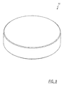
- the electronic lancing device 5 shown in FIG. 1 is a handheld cylindrical stand-alone model.
- the lancing device 5, however, can also be an integral component of a blood test sensor.
- An electronic lancing device 5 can take on many shapes such as rectangular, square and oval.
- the electronic lancing device 5 as shown in FIG. 1 comprises a housing 10, a cover 12, a power button 20, a firing button 22, a LED display 24, an end cap 25, and a lancet 30.
- the housing 10 is manufactured from a plastic or similar material and comprises a cylinder-shaped housing 10 that allows access to the electronic circuit and other items located within the electronic lancing device 5.
- the cylindrical housing 10 has one closed end and one partially closed end.
- the cover 12 envelops the portion of the housing 10 that allows access to the internal electronic circuit.
- the cover 12 also comprises control signals such as the power button 20, the firing button 22 and the LED display 24.
- the power button 20 is a relatively small article that protrudes from one external wall of the cover 12 in accordance with one embodiment of the present invention.
- a user activates the electronic lancing device by depressing the power button 20.
- the power button 20 could be disposed on one end of the electronic lancing device 5.
- the power button 20 protrudes from an external surface of the housing 10.
- the power button 20 could be circular, square, rectangular, or any other shape that would facilitate simple firing of the firing button 22.
- the firing button 22 is another relatively small article that protrudes from the cover 12 and is disposed adjacent the power button 20.
- the firing button 22 embodying the present invention possesses at least one external feature that distinguishes it from the power button 20. It is contemplated in accordance with the present invention that the firing button 22 can be circular and the power button 20 can be rectangular, as shown in FIG. 1. It is also contemplated that the power button 20 and the firing button 22 can be hexagonal, pentagonal, or other shapes.
- the surface of either the power button 20 or the firing button 22 can be imprinted with other distinguishing features, for example, a dimple or a pimple, in order to distinguish from the other button. It is also contemplated that the firing button 22 may protrude from an external surface of the housing 10.
- the color exhibited by the LED display 24 notifies the user if the lancing device 5 is operable.
- the optional LED display 24 can be disposed adjacent the firing button 22 on the cover 12.
- the LED display 24 may exhibit a red light if the electronic lancing device 5 is not prepared for operation and a green light if the electronic lancing device 5 is prepared for operation. It is contemplated in accordance with one embodiment of the present invention that the LED display 24 can exhibit alternative colors to indicate if the electronic lancing device can be operated.
- the end cap 25 is a cylindrical plastic article with openings at each end.
- the lancet 30 is a narrow sharply pointed object removably attached to a bobbin and designed to penetrate human skin.
- the end cap 25 serves both to protect the lancet 30 from damage and to protect the user from inadvertent contact with the sharply pointed lancet 30. Additionally, the end cap 25 is replaceable to protect multiple users and to control the depth of puncture.
- FIG. 1 depicts the lancet 30 being fully disposed within the end cap 25, referred to as the "retracted position.” After the user depresses the firing button 22, the lancet advances from within the end cap to the piercing site to pierce the skin. The lancet is referred to as being in the "activated position" when it has advanced from within the end cap into the piercing site, as further described below.
- a user selects and prepares a puncture or lancing site in the finger or other site, removes the end cap 25 to insert a lancet 30 into one end of the bobbin 35 (FIG. 2). The user then replaces the end cap 25 and presses the end cap 25 against the skin at the selected puncture or lancing site.
- the user After activating the electronic lancing device 5 with the power button 20 and ensuring that the light exhibited by the LED display 24 indicates that the electronic lancing device is operable, the user initiates the lancing process by depressing the firing button 22.
- the electronic lancing device 5 is then removed from the puncture or lancing site to reveal a body fluid such as capillary blood or interstitial fluid. The fluid can be then touched or put into contact with a blood or interstitial fluid test sensor where the desired tests are performed.
- the user can then remove the end cap 25 and lancet 30 from the electronic lancing device 5.
- FIG. 2 depicts an exploded view of the electronic lancing device 5 of one embodiment of the present invention.
- the electronic lancing device 5 comprises a housing 10, a cover 12, batteries 15, a power button 20, a firing button 22, a LED display 24, an end cap 25, a lancet 30, a bobbin 35, a steel shell 45, a magnet 50, a steel block 52 and adhesive 54.
- the housing 10 comprises a generally tubular body member with a cover 12 and two ends, a closed rear end 60 and an open front end 65.
- the housing 10 protects and provides an outer casing for the internal components of the electronic lancing device 5.
- the housing is made of a suitable plastic material.
- a voltage source such as one or more batteries 15 is connected to an electronic circuit 40.
- the electronic lancing device 5 as shown in FIG. 2 comprises two AAA-size batteries. It is contemplated that 9 Volt or AA-size, AAAA-size, N cell, coin or any other suitable type of battery could be used within the electronic lancing device 5. It is also contemplated in accordance with the present invention that the electronic lancing device 5 could use a rechargeable battery.
- the battery 15 In order to effectuate an adequate advancement and retraction of the lancet into and out of the skin, the battery 15 carries a suitable voltage and current generating capabilities.
- the open front end 65 of the housing 10 provides a means for the inward and outward movement of the lancet 30 and bobbin 35 during operation of the electronic lancing device 5.
- the firing button 22 initiates the sequence by which the lancet is propelled into the puncture site and retracted therefrom out of the puncture site.
- the timing chip of the in-stroke and control circuitry creates sufficient current to enable the bobbin 35 and the removably-attached lancet 30 to advance from their initial position into the puncture or lancing site.
- the out-stroke creates sufficient repulsive magnetic field to force the lancet and bobbin 35 away from its initial "retracted” position and into the "activated position.”
- the lancet 30 is in its retracted position when it is fully within the end cap 25 and in its activated position when it is fully extended away from the magnet 50.
- the electronic lancing device At its activated position, the electronic lancing device has completed the out-stroke and the lancet is fully inserted into the puncture site.
- the firing button 22 is connected to at least one wire leading to the electronic circuit 40.
- Another timer circuit initiates an in-stroke.
- the timing circuit of the in-stroke reverses the current, creating enough attractive force to retract the lancet 30 from the skin and return the bobbin 35 and the lancet 30 to the retracted position within the end cap 25.
- One embodiment of the present invention allows the user to initiate the lancing process only when a lancet 30 has been inserted into the bobbin 35.
- a steel shell 45 comprises a generally tubular body member 305 with a closed end 310, an open end 315 and guide arms 320.
- the steel shell 45 disposed within the housing 10, serves to house the magnet 50 and a steel block 52.
- the steel shell further provides partial housing for the bobbin 35.
- the steel shell 45 proscribes the path of motion of the free moving bobbin 35 during both the out-stroke and in-stroke.
- Extending beyond the open end 315 of the steel shell 45 is at least one guide arm 320.
- the guide arms 320 allow for only one directional translation motion. It is preferable that there are at least two guide arms 320.
- the bobbin 35 is expelled out of the steel shell 45 and toward the lancing site.
- the in-stroke provides sufficient attractive force to attract the bobbin 35 into the steel shell 45.
- the duration of the end stroke is sufficient to prevent bouncing of the bobbin 35, thus preventing multiple punctures.
- the open end 315 of the steel shell 45 is directed toward the open end 65 of the housing 10.
- the open end 315 of the steel shell 45 provides an opening large enough for the magnet 50 and the steel block 52 to be inserted into the steel shell 45.
- the open end 315 also provides sufficient opening for the bobbin 35 to be partially inserted into the steel shell 45.
- a magnet 50 is mounted within the steel shell 45.
- the magnet 50 is coaxially centered and mounted inside the steel shell 45, within the housing 10.
- the magnet 50 comprises a solid, generally cylindrical body member 405 that fits within the steel shell 45.
- an adhesive 54 is placed on both the top surface and bottom surface of the magnet 50. It is contemplated in accordance with the present invention that the adhesive 54 is a contact layer containing adhering materials on both sides.
- the adhesive 54 on the bottom surface of the magnet 50 will attach the bottom surface of the magnet 50 to the steel shell 45.
- the adhesive 54 on the top surface of the magnet 50 will attach the top surface to a steel block 52.
- a bobbin 35 comprises a flat disc 505. a first surface 507, a second surface 509, a first generally tubular body member 511, and a second generally tubular body member 515.
- the generally tubular body member 511 is located and attached to the first surface 507 of the flat disc 505.
- a second generally tubular body member 515 is located and attached to the second surface 509 of the flat disc 505.
- At least a portion of the second generally tubular body member 515 is wrapped by a coil of wire 520 (e.g ., 33-gauge wire) winding in one or more layers. It is contemplated in accordance with the present invention that the wire 520 may encircle all or a portion of the length of the second tubular body member 515. Furthermore, as shown in FIG. 6, the two ends of the coil of wire 520 extend through a slot 525 in the flat disc 505. Contact adhesive is applied to the wire 520 to retain its place around the second generally tubular body member 515. Ribs 530 and 540 are higher than the layers of coil 520 in order to protect the coil of wire 520 from rubbing during operation.
- a coil of wire 520 e.g ., 33-gauge wire
- the two timer chips and control circuit direct the current through the wire, creating enough repulsive forces to expel a cap 700 (FIGS. 6 & 7) and the lancet 30 from its retracted position toward the lancing site and attract it back to the retracted position.
- the cap 700 contains a hollow tubular section 702 centrally located to enable the cap 700 to fit over the top of the first generally tubular body member 511.
- a slot 705 exists on both sides of the cap 700.
- the wires that extend from the slots 525 of the disc 505 are attached through the slots 705 into channels 710 of the cap 700.
- the wires are connected from the channels 710 to the electronic circuit 40.
- a compression spring 605 is located between the cap 700 and the disc 505. As current flows through the wire 520, the bobbin 35 and lancet 30 extend towards the puncture site.
- FIG. 7 shows a front view of the bobbin-coil-cap assembly of one embodiment of the present invention.
- a removable end cap 25 can be attached to the tubular body member 702.
- the end cap 25 consists of a generally tubular body member 805 with an open end and a partially closed end.
- the open end of the end cap 25 is designed to be attached to the tubular body member 702 of the cap 700.
- the inner diameter of the end cap 25 at the open end is larger than the outer diameter of the tubular body member 702 to allow the end cap 25 to fit over the tubular body member 702.
- the outer diameter of tubular member 511 is less than the inner diameter of this tubular body member 702.
- the partially closed end of the end cap 25 contains an opening 810 that allows the tip of the lancet 30 to pass through. Prior to and post operation, the lancet is safely housed within the end cap 25.
- the electronic lancing device 5 can take on a cubic shape instead of a generally tubular shape.
- each of the items previously referred to possess a generally tubular shape might have a generally cubic shape, with a square or rectangular shape.
- other shapes exist that will enable this invention.
- a steel block 52 is coaxially centered and mounted on top of the magnet 50.
- the steel block 52 brings the majority of the magnetic flux lines to intersect the coils in order for the electronic lancing device to achieve maximum efficiency.
- the steel block 52 may be a solid generally cylindrical disc formed from steel. Magnetic flux lines return to the magnet through the steel shell 45.
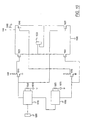
- the electronic circuit 40 of the present invention could be designed in a variety of ways.
- the electronic circuit of FIG. 10 comprises a switch 1005, two timing chips 1010 and 1060, several resistors and at least two transistors.
- the switch 1005, as shown in FIG. 10 of the electronic circuit 40 forces a falling edge transition at the trigger of pin 2 of a TLC555-timing chip 1010.
- the timing chip 1010 regulates the delivery of the bobbin and lancet.
- the timing chip 1010 triggers the out-stroke during which the lancet is advanced into the puncture or lancing site. It is preferable that the duration of the out-stroke is adjustable, being generally less than about 7 milliseconds.
- Transistors 1015, 1035, 1040 and 1020 are of the n-channel variety, so they are “on,” or conduct current, when their gate voltages are at a high voltage relative to the voltage source, Vdd, and do not conduct current when their gate voltages are at a low voltage.
- Transistors 1025 and 1045 are of the p-channel variety, so they are “on” or conduct current when their gate voltages are at a low voltage relative to the voltage source, Vdd, and do not conduct current when their gate voltages are at a high voltage.
- the timing chip 1010 controls the voltage at the gates of a level-shifter transistor 1015 and transistor 1020.
- transistors 1015 and 1020 turn on, and simultaneously the gate of transistor 1025 decreases, or “goes low,” so transistor 1025 turns on.
- the gates of transistors 1035 and 1040 are low, so these transistors are off, and the gate of transistor 1045 is high, so transistor 1045 is off. Therefore the current path through the coil 1030 is from Vdd through transistor 1025, through the coil 1030, and then 1020 to ground, 1090.
- This current through the coil causes a repulsive magnetic field in the coil 1030 that causes the voice coil 1030 and the bobbin 35 to be repulsed by the permanent magnet out of the steel shell 45, this action comprising the out-stroke.
- This magnetic field develops enough energy to allow the lancet to surge away from the magnet 50 and into the puncture or lancing site.
- the transistors 1020 and 1025 allow adequate current from the power source, Vdd, and charged capacitor 1080 during the delivery of the lancet and the bobbin into the puncture site.
- the timer 1010 After a time set by the resistor 1050 and the capacitor 1070, the timer 1010 times out, decreasing the voltage on the gates of transistors 1015 and 1020, and simultaneously, the falling edge transition of the out-stroke triggers pin 2 of a second TLC555-timing chip 1060.
- the timing chip 1060 regulates the retraction of the bobbin and lancet.
- the timing chip 1060 causes the gates of transistors 1035 and 1040 to go high, turning transistors 1035 and 1040 on, and simultaneously the gate of transistor 1045 goes low, so transistor 1045 turns on.
- the gates of transistors 1015 and 1020 are low, so these transistors are off, and the gate of transistor 1025 is high, so transistor 1025 is off.
- the current path through the coil 1030 is from Vdd through transistor 1045, through the coil 1030, and then 1040 to ground, 1090.
- the direction of this current through the coil causes an attractive magnetic field in the coil 1030 which causes coil 1030 and the bobbin 35 to be attracted by the permanent magnet into the steel shell 45.
- This action comprises the in-stroke during which the lancet is removed or pulled from the puncture or lancing site.
- the transistors 1040 and 1045 allow adequate current from the power source, Vdd, and charged capacitor 1080 during the extraction of the lancet and the bobbin from the puncture site.
- the timer 1060 After a time set by resistor 1055 and capacitor 1075, the timer 1060 times out, leaving the bobbin in the retracted position, held by the spring 605.
- the in-stroke is of sufficient duration so as to eliminate bouncing of the bobbin, resulting in reduced pain to the user.
- the duration of the in-stroke is from about 10 to about 15 milliseconds.
Abstract
Description
- The present invention relates generally to an electronic lancing device. More particularly, the present invention relates to an electronic lancing device comprising an electronic circuit that controls the movement of the lancet, mounted on a floating voice coil (bobbin) over a stationary magnet in a metal housing.
- Lancing devices are used for obtaining a body fluid such as capillary blood or interstitial fluid from various body sites. A typical user of a mechanical lancing device is a person in a program of self-blood glucose monitoring for treatment of diabetes. , Generally, the user depresses a firing button on a lancing device at a selected puncture site to activate the lancing device to puncture the skin at the site. Once the skin has been punctured and the lancet retracts from the lancing site, a small amount of body fluid such as capillary blood or interstitial fluid forms on the skin at the puncture. The drop of body fluid on the surface of the skin at the puncture site is then applied to a test sensor.
- Mechanical lancing devices such as disclosed in US 5,368,047; US 5,188,118; US 5,029,583; US 4,653,513; US 4,462,405; US 4,449,529; US 4,203,446; US 3,208,452 are well known. The advancement and retraction of the lancet in all these devices is produced by a combination of two or more mechanical springs. A major problem many existing mechanical lancing devices face is the amount of pain experienced by the user of the device. Three significant reasons related to the lancing devices contribute to an increased amount of user pain. The lancets in many lancing devices undergo side-to-side vibration while moving to puncture the skin. This vibration can lead to an irregular puncture, causing unnecessary pain and discomfort to a user.
- Another reason contributing to increased user pain associated with existing mechanical lancing devices if the repeated bouncing into and out of the skin that occurs upon insertion of the lancet into the puncture or lancing site. Typical mechanical lancing devices have been shown to penetrate the skin two to six times before the lancet stops oscillating.
- A further reason for elevated user pain is the relatively slow speed at which the lancet travels into and from the skin and the period of time that the lancet remains inside the skin or "dwell time." A slower speed of lancet puncture, a longer duration of dwell time inside the skin, and a slower speed of lancet retraction all augment the amount of pain that a user experiences.
- Accordingly, there exists a need for a lancing device that reduces user pain by eliminating the lancet from bouncing into and out of the skin, eliminating or reducing the vibration of the lancet when fired into the puncture site, and increasing the speed at which the lancet enters in and retracts from the skin, and controlling the dwell time of the lancet inside the skin.
- The present invention provides an electronic lancing device comprising a stationary magnet mounted in a metal shell. A free-floating bobbin with attached coil is disposed over the magnet. The reciprocating movement of the bobbin's forward, reverse and dwell positions are precisely controlled by an electronic circuit.
- It has been discovered that the use of a substantially free-standing voice coil within a lancing device in coordination and combination with a stationary magnet and electronic circuit renders a much improved lancing device. The minimal weight of the free standing voice coil and the attractive forces of the magnet allow the electronic circuit to maintain excellent control over the advancement and retraction of a lancet. When the electronic lancing device is initiated by a user, the electronic circuit within the electronic lancing device provides sufficient current through the voice coil such that the coil, bobbin and lancet are repulsed from the magnet and propelled into the puncture site. The electronic circuit subsequently reverses the current to supply sufficient attractive current through the voice coil such that the lancet is retracted from the puncture site and pulled toward the magnet within the housing of the electronic lancing device. The electronic circuit can also control the pause or dwell time between the advancement and the retraction of the bobbin and lancet.
- Other objects and advantages of the invention will become apparent upon reading the following detailed description and upon reference to the drawings in which:
- FIG. 1 is an assembly view of the retracted position of one embodiment of the electronic lancing device;
- FIG. 2 is an exploded view of an electronic lancing device embodying the present invention;
- FIG. 3 is an isometric view of the steel shell of one embodiment of the present invention;
- FIG. 4 is an isometric view of the magnet of one embodiment of the present invention;
- FIG. 5 is an isometric view of the bobbin of one embodiment of the present invention;
- FIG. 6 is an exploded view of bobbin-coil-cap assembly of one embodiment of the present invention;
- FIG. 7 is an assembled view of bobbin-coil-cap assembly of one embodiment of the present invention;
- FIG. 8 is an isometric view of the end cap of one embodiment of the present invention;
- FIG. 9 is an isometric view of the steel block of one embodiment of the present invention; and
- FIG. 10 is a schematic view of an electronic circuit of one embodiment of the present invention.
-
- While this invention is satisfied by embodiments in many different forms, there is shown in the drawings and will herein be described in detail preferred embodiments of the invention.
- The electronic lancing device of the present invention is generally designated by the
reference number 5 in the drawings. Theelectronic lancing device 5 shown in FIG. 1 is a handheld cylindrical stand-alone model. Thelancing device 5, however, can also be an integral component of a blood test sensor. Anelectronic lancing device 5 can take on many shapes such as rectangular, square and oval. According to one embodiment of the present invention, theelectronic lancing device 5 as shown in FIG. 1 comprises ahousing 10, acover 12, apower button 20, afiring button 22, aLED display 24, anend cap 25, and alancet 30. As shown in FIG. 1, thehousing 10 is manufactured from a plastic or similar material and comprises a cylinder-shaped housing 10 that allows access to the electronic circuit and other items located within theelectronic lancing device 5. Thecylindrical housing 10 has one closed end and one partially closed end. Thecover 12 envelops the portion of thehousing 10 that allows access to the internal electronic circuit. Thecover 12 also comprises control signals such as thepower button 20, thefiring button 22 and theLED display 24. Thepower button 20 is a relatively small article that protrudes from one external wall of thecover 12 in accordance with one embodiment of the present invention. In order to operate theelectronic lancing device 5, a user activates the electronic lancing device by depressing thepower button 20. It is also contemplated that thepower button 20 could be disposed on one end of theelectronic lancing device 5. It is further contemplated that thepower button 20 protrudes from an external surface of thehousing 10. It is further contemplated that thepower button 20 could be circular, square, rectangular, or any other shape that would facilitate simple firing of thefiring button 22. - After the
power button 20 is depressed and theelectronic lancing device 5 is aligned against the puncture site, the user depresses thefiring button 22 to initiate the lancing process. Thefiring button 22 is another relatively small article that protrudes from thecover 12 and is disposed adjacent thepower button 20. In order for visually impaired users to operate theelectronic lancing device 5, thefiring button 22 embodying the present invention possesses at least one external feature that distinguishes it from thepower button 20. It is contemplated in accordance with the present invention that thefiring button 22 can be circular and thepower button 20 can be rectangular, as shown in FIG. 1. It is also contemplated that thepower button 20 and thefiring button 22 can be hexagonal, pentagonal, or other shapes. It is further contemplated that the surface of either thepower button 20 or thefiring button 22 can be imprinted with other distinguishing features, for example, a dimple or a pimple, in order to distinguish from the other button. It is also contemplated that thefiring button 22 may protrude from an external surface of thehousing 10. - Before depressing the
firing button 22, the color exhibited by theLED display 24 notifies the user if thelancing device 5 is operable. Theoptional LED display 24 can be disposed adjacent thefiring button 22 on thecover 12. For example, theLED display 24 may exhibit a red light if theelectronic lancing device 5 is not prepared for operation and a green light if theelectronic lancing device 5 is prepared for operation. It is contemplated in accordance with one embodiment of the present invention that theLED display 24 can exhibit alternative colors to indicate if the electronic lancing device can be operated. - As shown in FIG. 1, the
end cap 25 is a cylindrical plastic article with openings at each end. Thelancet 30 is a narrow sharply pointed object removably attached to a bobbin and designed to penetrate human skin. Theend cap 25 serves both to protect thelancet 30 from damage and to protect the user from inadvertent contact with the sharply pointedlancet 30. Additionally, theend cap 25 is replaceable to protect multiple users and to control the depth of puncture. FIG. 1 depicts thelancet 30 being fully disposed within theend cap 25, referred to as the "retracted position." After the user depresses thefiring button 22, the lancet advances from within the end cap to the piercing site to pierce the skin. The lancet is referred to as being in the "activated position" when it has advanced from within the end cap into the piercing site, as further described below. - A user selects and prepares a puncture or lancing site in the finger or other site, removes the
end cap 25 to insert alancet 30 into one end of the bobbin 35 (FIG. 2). The user then replaces theend cap 25 and presses theend cap 25 against the skin at the selected puncture or lancing site. After activating theelectronic lancing device 5 with thepower button 20 and ensuring that the light exhibited by theLED display 24 indicates that the electronic lancing device is operable, the user initiates the lancing process by depressing thefiring button 22. Theelectronic lancing device 5 is then removed from the puncture or lancing site to reveal a body fluid such as capillary blood or interstitial fluid. The fluid can be then touched or put into contact with a blood or interstitial fluid test sensor where the desired tests are performed. The user can then remove theend cap 25 andlancet 30 from theelectronic lancing device 5. - FIG. 2 depicts an exploded view of the
electronic lancing device 5 of one embodiment of the present invention. Theelectronic lancing device 5 comprises ahousing 10, acover 12,batteries 15, apower button 20, afiring button 22, aLED display 24, anend cap 25, alancet 30, abobbin 35, asteel shell 45, amagnet 50, asteel block 52 and adhesive 54. - The
housing 10 comprises a generally tubular body member with acover 12 and two ends, a closedrear end 60 and an openfront end 65. Thehousing 10 protects and provides an outer casing for the internal components of theelectronic lancing device 5. In one embodiment of thehousing 10, the housing is made of a suitable plastic material. A voltage source such as one ormore batteries 15 is connected to anelectronic circuit 40. Theelectronic lancing device 5 as shown in FIG. 2 comprises two AAA-size batteries. It is contemplated that 9 Volt or AA-size, AAAA-size, N cell, coin or any other suitable type of battery could be used within theelectronic lancing device 5. It is also contemplated in accordance with the present invention that theelectronic lancing device 5 could use a rechargeable battery. In order to effectuate an adequate advancement and retraction of the lancet into and out of the skin, thebattery 15 carries a suitable voltage and current generating capabilities. The openfront end 65 of thehousing 10 provides a means for the inward and outward movement of thelancet 30 andbobbin 35 during operation of theelectronic lancing device 5. - The
firing button 22 initiates the sequence by which the lancet is propelled into the puncture site and retracted therefrom out of the puncture site. After thefiring button 22 is depressed, the timing chip of the in-stroke and control circuitry, as described below, creates sufficient current to enable thebobbin 35 and the removably-attachedlancet 30 to advance from their initial position into the puncture or lancing site. The out-stroke creates sufficient repulsive magnetic field to force the lancet andbobbin 35 away from its initial "retracted" position and into the "activated position." As used herein, thelancet 30 is in its retracted position when it is fully within theend cap 25 and in its activated position when it is fully extended away from themagnet 50. At its activated position, the electronic lancing device has completed the out-stroke and the lancet is fully inserted into the puncture site. In order to initiate the out-stroke, thefiring button 22 is connected to at least one wire leading to theelectronic circuit 40. - After the out-stroke creates sufficient repulsive charge to force the
lancet 30 from its initial position within theend cap 25 away from themagnet 50 and into the puncture site, another timer circuit, as detailed below, initiates an in-stroke. The timing circuit of the in-stroke reverses the current, creating enough attractive force to retract thelancet 30 from the skin and return thebobbin 35 and thelancet 30 to the retracted position within theend cap 25. One embodiment of the present invention allows the user to initiate the lancing process only when alancet 30 has been inserted into thebobbin 35. - As shown in FIG. 2 and detailed in FIG. 3, a
steel shell 45 comprises a generallytubular body member 305 with aclosed end 310, anopen end 315 and guidearms 320. Thesteel shell 45, disposed within thehousing 10, serves to house themagnet 50 and asteel block 52. The steel shell further provides partial housing for thebobbin 35. During operation of theelectronic lancing device 5, thesteel shell 45 proscribes the path of motion of the free movingbobbin 35 during both the out-stroke and in-stroke. Extending beyond theopen end 315 of thesteel shell 45 is at least oneguide arm 320. Theguide arms 320 allow for only one directional translation motion. It is preferable that there are at least two guidearms 320. During the out-stroke of theelectronic lancing device 5, thebobbin 35 is expelled out of thesteel shell 45 and toward the lancing site. The in-stroke provides sufficient attractive force to attract thebobbin 35 into thesteel shell 45. The duration of the end stroke is sufficient to prevent bouncing of thebobbin 35, thus preventing multiple punctures. - The
open end 315 of thesteel shell 45 is directed toward theopen end 65 of thehousing 10. Theopen end 315 of thesteel shell 45 provides an opening large enough for themagnet 50 and thesteel block 52 to be inserted into thesteel shell 45. Theopen end 315 also provides sufficient opening for thebobbin 35 to be partially inserted into thesteel shell 45. - A
magnet 50 is mounted within thesteel shell 45. Themagnet 50 is coaxially centered and mounted inside thesteel shell 45, within thehousing 10. As shown in FIG. 4, themagnet 50 comprises a solid, generallycylindrical body member 405 that fits within thesteel shell 45. As shown in FIG. 2, an adhesive 54 is placed on both the top surface and bottom surface of themagnet 50. It is contemplated in accordance with the present invention that the adhesive 54 is a contact layer containing adhering materials on both sides. The adhesive 54 on the bottom surface of themagnet 50 will attach the bottom surface of themagnet 50 to thesteel shell 45. The adhesive 54 on the top surface of themagnet 50 will attach the top surface to asteel block 52. - As shown in FIG. 5, a
bobbin 35 comprises aflat disc 505. afirst surface 507, asecond surface 509, a first generallytubular body member 511, and a second generallytubular body member 515. The generallytubular body member 511 is located and attached to thefirst surface 507 of theflat disc 505. A second generallytubular body member 515 is located and attached to thesecond surface 509 of theflat disc 505. - At least a portion of the second generally
tubular body member 515 is wrapped by a coil of wire 520 (e.g., 33-gauge wire) winding in one or more layers. It is contemplated in accordance with the present invention that thewire 520 may encircle all or a portion of the length of the secondtubular body member 515. Furthermore, as shown in FIG. 6, the two ends of the coil ofwire 520 extend through aslot 525 in theflat disc 505. Contact adhesive is applied to thewire 520 to retain its place around the second generallytubular body member 515.Ribs coil 520 in order to protect the coil ofwire 520 from rubbing during operation. The two timer chips and control circuit, as described below, direct the current through the wire, creating enough repulsive forces to expel a cap 700 (FIGS. 6 & 7) and thelancet 30 from its retracted position toward the lancing site and attract it back to the retracted position. - Further comprising the
bobbin 35 is a first generallytubular body member 511 attached to thefirst surface 507, as shown in FIG.6. Thecap 700 contains ahollow tubular section 702 centrally located to enable thecap 700 to fit over the top of the first generallytubular body member 511. Aslot 705 exists on both sides of thecap 700. The wires that extend from theslots 525 of thedisc 505 are attached through theslots 705 intochannels 710 of thecap 700. The wires are connected from thechannels 710 to theelectronic circuit 40. Acompression spring 605 is located between thecap 700 and thedisc 505. As current flows through thewire 520, thebobbin 35 andlancet 30 extend towards the puncture site. Upon retraction, thebobbin 35,lancet 30 and theend cap 25 return to the original retracted position. The purpose ofcompression spring 605 is to maintain the retracted position of thebobbin 35 when not energized. FIG. 7 shows a front view of the bobbin-coil-cap assembly of one embodiment of the present invention. - A
removable end cap 25 can be attached to thetubular body member 702. As shown in FIG. 8, theend cap 25 consists of a generallytubular body member 805 with an open end and a partially closed end. The open end of theend cap 25 is designed to be attached to thetubular body member 702 of thecap 700. The inner diameter of theend cap 25 at the open end is larger than the outer diameter of thetubular body member 702 to allow theend cap 25 to fit over thetubular body member 702. The outer diameter oftubular member 511 is less than the inner diameter of thistubular body member 702. The partially closed end of theend cap 25 contains anopening 810 that allows the tip of thelancet 30 to pass through. Prior to and post operation, the lancet is safely housed within theend cap 25. - Since the present invention can be satisfied by embodiments in many different forms, it is contemplated in accordance with the present invention that the
electronic lancing device 5 can take on a cubic shape instead of a generally tubular shape. Similarly, each of the items previously referred to possess a generally tubular shape might have a generally cubic shape, with a square or rectangular shape. Furthermore, it is also contemplated that other shapes exist that will enable this invention. - As generally shown in FIG. 2 and further shown by FIG. 9, a
steel block 52 is coaxially centered and mounted on top of themagnet 50. Thesteel block 52 brings the majority of the magnetic flux lines to intersect the coils in order for the electronic lancing device to achieve maximum efficiency. Thesteel block 52 may be a solid generally cylindrical disc formed from steel. Magnetic flux lines return to the magnet through thesteel shell 45. - The
electronic circuit 40 of the present invention could be designed in a variety of ways. For example, the electronic circuit of FIG. 10 comprises aswitch 1005, two timingchips firing button 22, theswitch 1005, as shown in FIG. 10, of theelectronic circuit 40 forces a falling edge transition at the trigger of pin 2 of a TLC555-timing chip 1010. Thetiming chip 1010 regulates the delivery of the bobbin and lancet. Thetiming chip 1010 triggers the out-stroke during which the lancet is advanced into the puncture or lancing site. It is preferable that the duration of the out-stroke is adjustable, being generally less than about 7 milliseconds. It is more preferable that the duration of the out-stroke is as short as possible.Transistors Transistors timing chip 1010 controls the voltage at the gates of a level-shifter transistor 1015 andtransistor 1020. When the voltage at these gates increases (hereinafter referred to as "goes high"),transistors transistor 1025 decreases, or "goes low," sotransistor 1025 turns on. During this time, the gates oftransistors transistor 1045 is high, sotransistor 1045 is off. Therefore the current path through thecoil 1030 is from Vdd throughtransistor 1025, through thecoil 1030, and then 1020 to ground, 1090. The direction of this current through the coil causes a repulsive magnetic field in thecoil 1030 that causes thevoice coil 1030 and thebobbin 35 to be repulsed by the permanent magnet out of thesteel shell 45, this action comprising the out-stroke. This magnetic field develops enough energy to allow the lancet to surge away from themagnet 50 and into the puncture or lancing site. Thetransistors capacitor 1080 during the delivery of the lancet and the bobbin into the puncture site. - After a time set by the
resistor 1050 and thecapacitor 1070, thetimer 1010 times out, decreasing the voltage on the gates oftransistors timing chip 1060. Thetiming chip 1060 regulates the retraction of the bobbin and lancet. Thetiming chip 1060 causes the gates oftransistors transistors transistor 1045 goes low, sotransistor 1045 turns on. During this time, the gates oftransistors transistor 1025 is high, sotransistor 1025 is off. Therefore, the current path through thecoil 1030 is from Vdd throughtransistor 1045, through thecoil 1030, and then 1040 to ground, 1090. The direction of this current through the coil causes an attractive magnetic field in thecoil 1030 which causescoil 1030 and thebobbin 35 to be attracted by the permanent magnet into thesteel shell 45. This action comprises the in-stroke during which the lancet is removed or pulled from the puncture or lancing site. Thetransistors capacitor 1080 during the extraction of the lancet and the bobbin from the puncture site. After a time set byresistor 1055 andcapacitor 1075, thetimer 1060 times out, leaving the bobbin in the retracted position, held by thespring 605. The in-stroke is of sufficient duration so as to eliminate bouncing of the bobbin, resulting in reduced pain to the user. The duration of the in-stroke is from about 10 to about 15 milliseconds.
Claims (8)
- An electronic lancing device (5), comprising:a housing (10);a shell (45) being fixedly mounted within said housing (10);a magnet (50) fixedly mounted in said shell (45);a bobbin (35) being partially disposed in said shell (45) for reciprocating movement therein;a coil (520) having at least one winding disposed around said bobbin (35), said coil (520) being attached to said bobbin (35);a lancet (30) removably attached to said bobbin (35); andan electronic circuit (40) electrically coupled to said coil (520) for controlling the movement of said bobbin (35) to initiate the delivery and retraction of said bobbin and lancet.
- The electronic lancing device (5) of Claim 1, wherein said housing (10) further comprises a steel block (52) to allow at least a majority of the magnetic flux lines to intersect said coil (520).
- The electronic lancing device (5) of Claim 1 or 2, wherein said electronic circuit (40) comprises at least one timer circuit (1010, 1060), at least one wave-shaping amplifier circuit, at least one power transistor (1020, 1025, 1035, 1040) to provide current to the bobbin (35), and at least one capacitor (1070, 1080) to provide current to the bobbin (35).
- The electronic lancing device (5) of one of the Claims 1 to 3, wherein said electronic circuit comprises two timer circuits (1010, 1060).
- The electronic lancing device (5) of Claim 4, wherein one of said timer circuits (1010, 1060) regulates the delivery of said bobbin (35) and said lancet (30).
- The electronic lancing device (5) of Claim 5, wherein the duration of said delivery of said bobbin (35) is less than about 7 milliseconds.
- The electronic lancing device (5) of Claim 4, wherein one of said timer circuits (1010, 1060) regulates the retraction of said bobbin (35) and said lancet (30).
- The electronic lancing device (5) of Claim 7, wherein the duration of said retraction of said bobbin (35) is from about 10 to about 15 milliseconds.
Priority Applications (1)
| Application Number | Priority Date | Filing Date | Title |
|---|---|---|---|
| DK00123450T DK1101443T3 (en) | 1999-11-17 | 2000-11-06 | Electronic plugs |
Applications Claiming Priority (2)
| Application Number | Priority Date | Filing Date | Title |
|---|---|---|---|
| US441970 | 1989-11-28 | ||
| US09/441,970 US6364889B1 (en) | 1999-11-17 | 1999-11-17 | Electronic lancing device |
Publications (3)
| Publication Number | Publication Date |
|---|---|
| EP1101443A2 EP1101443A2 (en) | 2001-05-23 |
| EP1101443A3 EP1101443A3 (en) | 2002-01-09 |
| EP1101443B1 true EP1101443B1 (en) | 2005-02-09 |
Family
ID=23755030
Family Applications (1)
| Application Number | Title | Priority Date | Filing Date |
|---|---|---|---|
| EP00123450A Expired - Lifetime EP1101443B1 (en) | 1999-11-17 | 2000-11-06 | Electronic lancing device |
Country Status (10)
| Country | Link |
|---|---|
| US (1) | US6364889B1 (en) |
| EP (1) | EP1101443B1 (en) |
| JP (1) | JP3647738B2 (en) |
| AT (1) | ATE288703T1 (en) |
| AU (1) | AU777483B2 (en) |
| CA (1) | CA2324980C (en) |
| DE (1) | DE60018018T2 (en) |
| DK (1) | DK1101443T3 (en) |
| ES (1) | ES2235737T3 (en) |
| PT (1) | PT1101443E (en) |
Cited By (40)
| Publication number | Priority date | Publication date | Assignee | Title |
|---|---|---|---|---|
| US7648468B2 (en) | 2002-04-19 | 2010-01-19 | Pelikon Technologies, Inc. | Method and apparatus for penetrating tissue |
| US7666149B2 (en) | 1997-12-04 | 2010-02-23 | Peliken Technologies, Inc. | Cassette of lancet cartridges for sampling blood |
| US7674232B2 (en) | 2002-04-19 | 2010-03-09 | Pelikan Technologies, Inc. | Method and apparatus for penetrating tissue |
| US7682318B2 (en) | 2001-06-12 | 2010-03-23 | Pelikan Technologies, Inc. | Blood sampling apparatus and method |
| US7708701B2 (en) | 2002-04-19 | 2010-05-04 | Pelikan Technologies, Inc. | Method and apparatus for a multi-use body fluid sampling device |
| US7717863B2 (en) | 2002-04-19 | 2010-05-18 | Pelikan Technologies, Inc. | Method and apparatus for penetrating tissue |
| US7731729B2 (en) | 2002-04-19 | 2010-06-08 | Pelikan Technologies, Inc. | Method and apparatus for penetrating tissue |
| US7749174B2 (en) | 2001-06-12 | 2010-07-06 | Pelikan Technologies, Inc. | Method and apparatus for lancet launching device intergrated onto a blood-sampling cartridge |
| US7780631B2 (en) | 1998-03-30 | 2010-08-24 | Pelikan Technologies, Inc. | Apparatus and method for penetration with shaft having a sensor for sensing penetration depth |
| US7822454B1 (en) | 2005-01-03 | 2010-10-26 | Pelikan Technologies, Inc. | Fluid sampling device with improved analyte detecting member configuration |
| US7833171B2 (en) | 2002-04-19 | 2010-11-16 | Pelikan Technologies, Inc. | Method and apparatus for penetrating tissue |
| US7841992B2 (en) | 2001-06-12 | 2010-11-30 | Pelikan Technologies, Inc. | Tissue penetration device |
| US7850621B2 (en) | 2003-06-06 | 2010-12-14 | Pelikan Technologies, Inc. | Method and apparatus for body fluid sampling and analyte sensing |
| US7862520B2 (en) | 2002-04-19 | 2011-01-04 | Pelikan Technologies, Inc. | Body fluid sampling module with a continuous compression tissue interface surface |
| US7874994B2 (en) | 2002-04-19 | 2011-01-25 | Pelikan Technologies, Inc. | Method and apparatus for penetrating tissue |
| US7892183B2 (en) | 2002-04-19 | 2011-02-22 | Pelikan Technologies, Inc. | Method and apparatus for body fluid sampling and analyte sensing |
| US7901365B2 (en) | 2002-04-19 | 2011-03-08 | Pelikan Technologies, Inc. | Method and apparatus for penetrating tissue |
| US7909778B2 (en) | 2002-04-19 | 2011-03-22 | Pelikan Technologies, Inc. | Method and apparatus for penetrating tissue |
| US7909777B2 (en) | 2002-04-19 | 2011-03-22 | Pelikan Technologies, Inc | Method and apparatus for penetrating tissue |
| US7914465B2 (en) | 2002-04-19 | 2011-03-29 | Pelikan Technologies, Inc. | Method and apparatus for penetrating tissue |
| US7976476B2 (en) | 2002-04-19 | 2011-07-12 | Pelikan Technologies, Inc. | Device and method for variable speed lancet |
| US7988645B2 (en) | 2001-06-12 | 2011-08-02 | Pelikan Technologies, Inc. | Self optimizing lancing device with adaptation means to temporal variations in cutaneous properties |
| US8007446B2 (en) | 2002-04-19 | 2011-08-30 | Pelikan Technologies, Inc. | Method and apparatus for penetrating tissue |
| US8079960B2 (en) | 2002-04-19 | 2011-12-20 | Pelikan Technologies, Inc. | Methods and apparatus for lancet actuation |
| US8197421B2 (en) | 2002-04-19 | 2012-06-12 | Pelikan Technologies, Inc. | Method and apparatus for penetrating tissue |
| US8262614B2 (en) | 2003-05-30 | 2012-09-11 | Pelikan Technologies, Inc. | Method and apparatus for fluid injection |
| US8267870B2 (en) | 2002-04-19 | 2012-09-18 | Sanofi-Aventis Deutschland Gmbh | Method and apparatus for body fluid sampling with hybrid actuation |
| US8282576B2 (en) | 2003-09-29 | 2012-10-09 | Sanofi-Aventis Deutschland Gmbh | Method and apparatus for an improved sample capture device |
| US8333710B2 (en) | 2002-04-19 | 2012-12-18 | Sanofi-Aventis Deutschland Gmbh | Tissue penetration device |
| US8382682B2 (en) | 2002-04-19 | 2013-02-26 | Sanofi-Aventis Deutschland Gmbh | Method and apparatus for penetrating tissue |
| US8435190B2 (en) | 2002-04-19 | 2013-05-07 | Sanofi-Aventis Deutschland Gmbh | Method and apparatus for penetrating tissue |
| US8574895B2 (en) | 2002-12-30 | 2013-11-05 | Sanofi-Aventis Deutschland Gmbh | Method and apparatus using optical techniques to measure analyte levels |
| US8641644B2 (en) | 2000-11-21 | 2014-02-04 | Sanofi-Aventis Deutschland Gmbh | Blood testing apparatus having a rotatable cartridge with multiple lancing elements and testing means |
| US8652831B2 (en) | 2004-12-30 | 2014-02-18 | Sanofi-Aventis Deutschland Gmbh | Method and apparatus for analyte measurement test time |
| US8721671B2 (en) | 2001-06-12 | 2014-05-13 | Sanofi-Aventis Deutschland Gmbh | Electric lancet actuator |
| US8784335B2 (en) | 2002-04-19 | 2014-07-22 | Sanofi-Aventis Deutschland Gmbh | Body fluid sampling device with a capacitive sensor |
| US9060727B2 (en) | 2002-11-06 | 2015-06-23 | Abbott Diabetes Care Inc. | Automatic biological analyte testing meter with integrated lancing device and methods of use |
| US9144401B2 (en) | 2003-06-11 | 2015-09-29 | Sanofi-Aventis Deutschland Gmbh | Low pain penetrating member |
| US9314194B2 (en) | 2002-04-19 | 2016-04-19 | Sanofi-Aventis Deutschland Gmbh | Tissue penetration device |
| US9351680B2 (en) | 2003-10-14 | 2016-05-31 | Sanofi-Aventis Deutschland Gmbh | Method and apparatus for a variable user interface |
Families Citing this family (102)
| Publication number | Priority date | Publication date | Assignee | Title |
|---|---|---|---|---|
| US20020010406A1 (en) * | 1996-05-17 | 2002-01-24 | Douglas Joel S. | Methods and apparatus for expressing body fluid from an incision |
| EP1579814A3 (en) * | 1996-05-17 | 2006-06-14 | Roche Diagnostics Operations, Inc. | Methods and apparatus for sampling and analyzing body fluid |
| US7828749B2 (en) | 1996-05-17 | 2010-11-09 | Roche Diagnostics Operations, Inc. | Blood and interstitial fluid sampling device |
| US7666150B2 (en) * | 1996-05-17 | 2010-02-23 | Roche Diagnostics Operations, Inc. | Blood and interstitial fluid sampling device |
| US7235056B2 (en) | 1996-05-17 | 2007-06-26 | Amira Medical | Body fluid sampling device and methods of use |
| US7175641B1 (en) * | 1998-06-11 | 2007-02-13 | Stat Medical Devices, Inc. | Lancet having adjustable penetration depth |
| US8814896B2 (en) | 1999-11-02 | 2014-08-26 | Stat Medical Devices, Inc. | Single use lancet assembly |
| US20050070945A1 (en) | 1999-11-02 | 2005-03-31 | Steven Schraga | Single use lancet assembly |
| US6530937B1 (en) * | 2000-01-28 | 2003-03-11 | Stat Medical Devices, Inc. | Adjustable tip for a lancet device and method |
| DE10010694A1 (en) * | 2000-03-04 | 2001-09-06 | Roche Diagnostics Gmbh | Lancet including tipped needle with body surrounding tip |
| US7344546B2 (en) * | 2000-04-05 | 2008-03-18 | Pathway Medical Technologies | Intralumenal material removal using a cutting device for differential cutting |
| AU2001270299A1 (en) * | 2000-07-03 | 2002-01-14 | Kodiak Technologies, Inc. | Thermal container with data monitoring system |
| CA2425315C (en) * | 2000-10-13 | 2010-01-12 | Alza Corporation | Apparatus and method for piercing skin with microprotrusions |
| US7419481B2 (en) * | 2000-10-13 | 2008-09-02 | Alza Corporation | Apparatus and method for piercing skin with microprotrusions |
| DE10053974A1 (en) | 2000-10-31 | 2002-05-29 | Roche Diagnostics Gmbh | Blood collection system |
| MXPA03006421A (en) * | 2001-01-22 | 2004-12-02 | Hoffmann La Roche | Lancet device having capillary action. |
| EP1416851B1 (en) * | 2001-06-08 | 2006-08-09 | Roche Diagnostics GmbH | Bodily fluid sampling device and test media cassette to be used with such a device |
| US20020188223A1 (en) | 2001-06-08 | 2002-12-12 | Edward Perez | Devices and methods for the expression of bodily fluids from an incision |
| US9795747B2 (en) * | 2010-06-02 | 2017-10-24 | Sanofi-Aventis Deutschland Gmbh | Methods and apparatus for lancet actuation |
| WO2002100461A2 (en) | 2001-06-12 | 2002-12-19 | Pelikan Technologies, Inc. | Method and apparatus for improving success rate of blood yield from a fingerstick |
| WO2003088851A1 (en) | 2001-06-12 | 2003-10-30 | Pelikan Technologies, Inc. | Tissue penetration device |
| US7001344B2 (en) * | 2001-06-12 | 2006-02-21 | Pelikan Technologies, Inc. | Blood sampling device with diaphragm actuated lancet |
| US9427532B2 (en) | 2001-06-12 | 2016-08-30 | Sanofi-Aventis Deutschland Gmbh | Tissue penetration device |
| US9226699B2 (en) | 2002-04-19 | 2016-01-05 | Sanofi-Aventis Deutschland Gmbh | Body fluid sampling module with a continuous compression tissue interface surface |
| EP1423049A2 (en) * | 2001-08-29 | 2004-06-02 | Roche Diagnostics GmbH | Wicking methods and structures for use in sampling bodily fluids |
| DE10142232B4 (en) * | 2001-08-29 | 2021-04-29 | Roche Diabetes Care Gmbh | Process for the production of an analytical aid with a lancet and test element |
| WO2003039369A1 (en) * | 2001-09-26 | 2003-05-15 | Roche Diagnostics Gmbh | Method and apparatus for sampling bodily fluid |
| US7410468B2 (en) | 2002-04-19 | 2008-08-12 | Pelikan Technologies, Inc. | Method and apparatus for penetrating tissue |
| US8221334B2 (en) | 2002-04-19 | 2012-07-17 | Sanofi-Aventis Deutschland Gmbh | Method and apparatus for penetrating tissue |
| US7892185B2 (en) | 2002-04-19 | 2011-02-22 | Pelikan Technologies, Inc. | Method and apparatus for body fluid sampling and analyte sensing |
| AU2002367876A1 (en) * | 2002-04-19 | 2003-11-03 | Ray Freeman | Tissue penetration device |
| WO2003088835A2 (en) * | 2002-04-19 | 2003-10-30 | Pelikan Technologies, Inc. | Method and apparatus for penetrating tissue |
| US7524293B2 (en) * | 2002-04-19 | 2009-04-28 | Pelikan Technologies, Inc. | Method and apparatus for penetrating tissue |
| US9248267B2 (en) | 2002-04-19 | 2016-02-02 | Sanofi-Aventis Deustchland Gmbh | Tissue penetration device |
| EP1501402A4 (en) * | 2002-04-19 | 2008-07-02 | Pelikan Technologies Inc | Device and method for variable speed lancet |
| US8702624B2 (en) | 2006-09-29 | 2014-04-22 | Sanofi-Aventis Deutschland Gmbh | Analyte measurement device with a single shot actuator |
| US8360992B2 (en) | 2002-04-19 | 2013-01-29 | Sanofi-Aventis Deutschland Gmbh | Method and apparatus for penetrating tissue |
| US7141058B2 (en) * | 2002-04-19 | 2006-11-28 | Pelikan Technologies, Inc. | Method and apparatus for a body fluid sampling device using illumination |
| US9795334B2 (en) * | 2002-04-19 | 2017-10-24 | Sanofi-Aventis Deutschland Gmbh | Method and apparatus for penetrating tissue |
| US8715309B2 (en) | 2002-04-29 | 2014-05-06 | Steven Schraga | Lancet device |
| US7731900B2 (en) * | 2002-11-26 | 2010-06-08 | Roche Diagnostics Operations, Inc. | Body fluid testing device |
| US7265881B2 (en) * | 2002-12-20 | 2007-09-04 | Hewlett-Packard Development Company, L.P. | Method and apparatus for measuring assembly and alignment errors in sensor assemblies |
| US7582258B2 (en) * | 2002-12-23 | 2009-09-01 | Roche Diagnostics Operations, Inc. | Body fluid testing device |
| ES2522972T3 (en) | 2002-12-23 | 2014-11-19 | F.Hoffmann-La Roche Ag | Device for testing body fluids |
| US7621931B2 (en) * | 2003-05-20 | 2009-11-24 | Stat Medical Devices, Inc. | Adjustable lancet device and method |
| US20040267299A1 (en) * | 2003-06-30 | 2004-12-30 | Kuriger Rex J. | Lancing devices and methods of using the same |
| US7905898B2 (en) * | 2003-08-15 | 2011-03-15 | Stat Medical Devices, Inc. | Adjustable lancet device and method |
| GB2406794B (en) * | 2003-10-06 | 2008-03-05 | Inverness Medical Ltd | A lancing device using a piezoelectric actuator |
| US20050125017A1 (en) * | 2003-12-05 | 2005-06-09 | Paul Kudrna | Lancet device and method |
| US20050125019A1 (en) * | 2003-12-05 | 2005-06-09 | Paul Kudrna | Lancet device and method |
| EP1706026B1 (en) | 2003-12-31 | 2017-03-01 | Sanofi-Aventis Deutschland GmbH | Method and apparatus for improving fluidic flow and sample capture |
| US7819822B2 (en) | 2004-03-06 | 2010-10-26 | Roche Diagnostics Operations, Inc. | Body fluid sampling device |
| PT2705792E (en) | 2004-03-06 | 2015-07-07 | Hoffmann La Roche | Body fluid sampling device |
| CN101309642A (en) * | 2004-03-15 | 2008-11-19 | 香港澳维有限公司 | Lancet device and method of use |
| US7169116B2 (en) * | 2004-04-29 | 2007-01-30 | Lifescan, Inc. | Actuation system for a bodily fluid extraction device and associated methods |
| EP1751546A2 (en) | 2004-05-20 | 2007-02-14 | Albatros Technologies GmbH & Co. KG | Printable hydrogel for biosensors |
| EP1765194A4 (en) | 2004-06-03 | 2010-09-29 | Pelikan Technologies Inc | Method and apparatus for a fluid sampling device |
| US9775553B2 (en) * | 2004-06-03 | 2017-10-03 | Sanofi-Aventis Deutschland Gmbh | Method and apparatus for a fluid sampling device |
| US8257380B2 (en) * | 2004-06-29 | 2012-09-04 | Stat Medical Devices, Inc. | Adjustabable disposable/single-use lancet device and method |
| BRPI0515085A (en) * | 2004-09-09 | 2008-07-08 | Bayer Healthcare Llc | damping system for a lancet using compressed air |
| JP2008512194A (en) * | 2004-09-09 | 2008-04-24 | バイエル・ヘルスケア・エルエルシー | Single puncture lance fixture with depth adjustment and contact force control |
| US8142733B2 (en) * | 2004-10-21 | 2012-03-27 | Bayer Healthcare Llc | Sensor-dispensing device and mechanism for extracting sensor |
| US8105347B2 (en) * | 2004-11-16 | 2012-01-31 | Stat Medical Devices, Inc. | Adjustable disposable/single-use blade lancet device and method |
| US8066728B2 (en) * | 2004-11-30 | 2011-11-29 | Stat Medical Devices, Inc. | Disposable or single-use lancet device and method |
| US9289161B2 (en) | 2005-01-28 | 2016-03-22 | Stat Medical Divices, Inc. | Multi-lancet unit, method and lancet device using the multi-lancet unit, and method of assembling and/or making the multi-lancet unit |
| WO2006096630A1 (en) | 2005-03-04 | 2006-09-14 | Bayer Healthcare Llc | Lancet-release mechanism |
| CN101163445A (en) * | 2005-03-04 | 2008-04-16 | 拜尔保健有限公司 | Lancet-release mechanism |
| ATE484238T1 (en) | 2005-04-28 | 2010-10-15 | Bayer Healthcare Llc | PERMANENT MAGNET LANCET DEVICE |
| EP1903927A2 (en) * | 2005-06-30 | 2008-04-02 | Bayer Healthcare, LLC | Single-puncture lancing system |
| EP1901655B1 (en) * | 2005-07-13 | 2018-12-19 | Roche Diabetes Care GmbH | Lancet device |
| WO2007011645A1 (en) | 2005-07-14 | 2007-01-25 | Bayer Healthcare Llc | Lancing device for one skin puncture |
| WO2007019202A2 (en) | 2005-08-04 | 2007-02-15 | Bayer Healthcare Llc | Small lancing device |
| EP1759635A1 (en) * | 2005-09-03 | 2007-03-07 | Boehringer Mannheim Gmbh | Pricking method and hand held device therefore |
| US7704265B2 (en) | 2005-11-03 | 2010-04-27 | Stat Medical Devices, Inc. | Disposable/single-use blade lancet device and method |
| US20080092241A1 (en) * | 2006-10-11 | 2008-04-17 | Media Machines, Inc. | Provision and use of digital rights data for embedded content over networked systems |
| US8043318B2 (en) | 2007-02-08 | 2011-10-25 | Stat Medical Devices, Inc. | Push-button lance device and method |
| WO2008100818A1 (en) * | 2007-02-09 | 2008-08-21 | Stat Medical Devices, Inc | Multi-lancet unit, method and lancet device using the multi-lancet unit, and method of assembling and/or making the multi-lancet unit |
| ES2587021T3 (en) * | 2007-03-12 | 2016-10-20 | Ascensia Diabetes Care Holdings Ag | Lancet Ejection Mechanism |
| WO2008111933A1 (en) * | 2007-03-12 | 2008-09-18 | Bayer Healthcare Llc | Single-sensor meter system with no sensor handling and method of using the same |
| ES2326699T3 (en) * | 2007-03-14 | 2009-10-16 | F. Hoffmann-La Roche Ag | LANCETA DEVICE. |
| US8469986B2 (en) | 2007-03-30 | 2013-06-25 | Stat Medical Devices, Inc. | Lancet device with combined trigger and cocking mechanism and method |
| WO2008157610A1 (en) | 2007-06-19 | 2008-12-24 | Stat Medical Devices, Inc. | Lancet device with depth adjustment and lancet removal system and method |
| US9247898B2 (en) | 2007-08-10 | 2016-02-02 | Dynamic Magnetics, Llc | Magnetic lancet device |
| US7766846B2 (en) | 2008-01-28 | 2010-08-03 | Roche Diagnostics Operations, Inc. | Rapid blood expression and sampling |
| WO2009126900A1 (en) | 2008-04-11 | 2009-10-15 | Pelikan Technologies, Inc. | Method and apparatus for analyte detecting device |
| US8118824B2 (en) * | 2008-09-16 | 2012-02-21 | Roche Diagnostics Operations, Inc. | Magnetic powered lancing drive |
| EP2181651A1 (en) * | 2008-10-29 | 2010-05-05 | Roche Diagnostics GmbH | Instrument and system for producing a sample of a body liquid and for analysis thereof |
| US9375169B2 (en) | 2009-01-30 | 2016-06-28 | Sanofi-Aventis Deutschland Gmbh | Cam drive for managing disposable penetrating member actions with a single motor and motor and control system |
| US8965476B2 (en) | 2010-04-16 | 2015-02-24 | Sanofi-Aventis Deutschland Gmbh | Tissue penetration device |
| EP3821941A1 (en) | 2011-01-28 | 2021-05-19 | Stimwave Technologies Incorporated | Neural stimulator system |
| US8849412B2 (en) | 2011-01-28 | 2014-09-30 | Micron Devices Llc | Microwave field stimulator |
| US9220897B2 (en) | 2011-04-04 | 2015-12-29 | Micron Devices Llc | Implantable lead |
| JP6671843B2 (en) | 2011-04-04 | 2020-03-25 | マイクロン デヴァイシーズ リミテッド ライアビリティ カンパニー | Implantable lead |
| US8333716B1 (en) | 2011-06-21 | 2012-12-18 | Yofimeter, Llc | Methods for using an analyte testing device |
| US20130085349A1 (en) | 2011-06-21 | 2013-04-04 | Yofimeter, Llc | Analyte testing devices |
| US20120330188A1 (en) | 2011-06-21 | 2012-12-27 | Gadlight, Inc. | Cocking and Advancing Mechanism for Analyte Testing Device |
| WO2013019757A2 (en) | 2011-07-29 | 2013-02-07 | Stimwave Technologies Incorporated | Remote control of power or polarity selection for a neural stimulator |
| US9242103B2 (en) | 2011-09-15 | 2016-01-26 | Micron Devices Llc | Relay module for implant |
| US9254393B2 (en) | 2012-12-26 | 2016-02-09 | Micron Devices Llc | Wearable antenna assembly |
| US9409029B2 (en) | 2014-05-12 | 2016-08-09 | Micron Devices Llc | Remote RF power system with low profile transmitting antenna |
| US10070811B2 (en) | 2014-06-26 | 2018-09-11 | Stat Medical Devices, Inc. | Lancing device with depth adjustment and lancet removal system and method |
| USD806246S1 (en) | 2016-02-25 | 2017-12-26 | Steven Schraga | Lancet cover |
Family Cites Families (15)
| Publication number | Priority date | Publication date | Assignee | Title |
|---|---|---|---|---|
| US2714890A (en) * | 1953-08-06 | 1955-08-09 | Vang Alfred | Vibratory surgical instruments |
| US3086288A (en) * | 1955-04-20 | 1963-04-23 | Cavitron Ultrasonics Inc | Ultrasonically vibrated cutting knives |
| US3208452A (en) | 1960-09-08 | 1965-09-28 | Panray Parlam Corp | Surface treating device |
| US3673475A (en) * | 1970-09-15 | 1972-06-27 | Fred M Hufnagel | Pulse drive circuit for coils of dental impact tools and the like |
| US3832776A (en) * | 1972-11-24 | 1974-09-03 | H Sawyer | Electronically powered knife |
| US4154228A (en) * | 1976-08-06 | 1979-05-15 | California Institute Of Technology | Apparatus and method of inserting a microelectrode in body tissue or the like using vibration means |
| DE2642896C3 (en) | 1976-09-24 | 1980-08-21 | 7800 Freiburg | Precision snapper for setting standard stab wounds in the skin for diagnostic purposes |
| US4449529A (en) | 1981-11-18 | 1984-05-22 | Becton Dickinson And Company | Automatic retractable lancet assembly |
| US4462405A (en) | 1982-09-27 | 1984-07-31 | Ehrlich Joseph C | Blood letting apparatus |
| FR2555432A1 (en) * | 1983-11-25 | 1985-05-31 | Franceschi Claude | Method for puncturing blood vessels combining a needle propeller with a Doppler ultrasonograph which guides it |
| US4653513A (en) | 1985-08-09 | 1987-03-31 | Dombrowski Mitchell P | Blood sampler |
| US5029583A (en) | 1986-07-22 | 1991-07-09 | Personal Diagnostics, Inc. | Optical analyzer |
| US5188118A (en) | 1990-11-07 | 1993-02-23 | Terwilliger Richard A | Automatic biopsy instrument with independently actuated stylet and cannula |
| JP2630197B2 (en) | 1993-04-28 | 1997-07-16 | 株式会社ニッショー | Blood suction device |
| EP0798004A1 (en) * | 1996-03-29 | 1997-10-01 | Wagner, Wolfgang, Dr.med. | Means and related method for metabolism control of a living organism |
-
1999
- 1999-11-17 US US09/441,970 patent/US6364889B1/en not_active Expired - Lifetime
-
2000
- 2000-11-01 AU AU69666/00A patent/AU777483B2/en not_active Ceased
- 2000-11-01 CA CA002324980A patent/CA2324980C/en not_active Expired - Fee Related
- 2000-11-01 JP JP2000334300A patent/JP3647738B2/en not_active Expired - Fee Related
- 2000-11-06 DE DE60018018T patent/DE60018018T2/en not_active Expired - Lifetime
- 2000-11-06 DK DK00123450T patent/DK1101443T3/en active
- 2000-11-06 AT AT00123450T patent/ATE288703T1/en active
- 2000-11-06 PT PT00123450T patent/PT1101443E/en unknown
- 2000-11-06 ES ES00123450T patent/ES2235737T3/en not_active Expired - Lifetime
- 2000-11-06 EP EP00123450A patent/EP1101443B1/en not_active Expired - Lifetime
Cited By (72)
| Publication number | Priority date | Publication date | Assignee | Title |
|---|---|---|---|---|
| US7666149B2 (en) | 1997-12-04 | 2010-02-23 | Peliken Technologies, Inc. | Cassette of lancet cartridges for sampling blood |
| US7780631B2 (en) | 1998-03-30 | 2010-08-24 | Pelikan Technologies, Inc. | Apparatus and method for penetration with shaft having a sensor for sensing penetration depth |
| US8641644B2 (en) | 2000-11-21 | 2014-02-04 | Sanofi-Aventis Deutschland Gmbh | Blood testing apparatus having a rotatable cartridge with multiple lancing elements and testing means |
| US8282577B2 (en) | 2001-06-12 | 2012-10-09 | Sanofi-Aventis Deutschland Gmbh | Method and apparatus for lancet launching device integrated onto a blood-sampling cartridge |
| US8216154B2 (en) | 2001-06-12 | 2012-07-10 | Sanofi-Aventis Deutschland Gmbh | Tissue penetration device |
| US7682318B2 (en) | 2001-06-12 | 2010-03-23 | Pelikan Technologies, Inc. | Blood sampling apparatus and method |
| US8360991B2 (en) | 2001-06-12 | 2013-01-29 | Sanofi-Aventis Deutschland Gmbh | Tissue penetration device |
| US7749174B2 (en) | 2001-06-12 | 2010-07-06 | Pelikan Technologies, Inc. | Method and apparatus for lancet launching device intergrated onto a blood-sampling cartridge |
| US8721671B2 (en) | 2001-06-12 | 2014-05-13 | Sanofi-Aventis Deutschland Gmbh | Electric lancet actuator |
| US8343075B2 (en) | 2001-06-12 | 2013-01-01 | Sanofi-Aventis Deutschland Gmbh | Tissue penetration device |
| US7981055B2 (en) | 2001-06-12 | 2011-07-19 | Pelikan Technologies, Inc. | Tissue penetration device |
| US7841992B2 (en) | 2001-06-12 | 2010-11-30 | Pelikan Technologies, Inc. | Tissue penetration device |
| US8641643B2 (en) | 2001-06-12 | 2014-02-04 | Sanofi-Aventis Deutschland Gmbh | Sampling module device and method |
| US7850622B2 (en) | 2001-06-12 | 2010-12-14 | Pelikan Technologies, Inc. | Tissue penetration device |
| US8211037B2 (en) | 2001-06-12 | 2012-07-03 | Pelikan Technologies, Inc. | Tissue penetration device |
| US8206317B2 (en) | 2001-06-12 | 2012-06-26 | Sanofi-Aventis Deutschland Gmbh | Tissue penetration device |
| US8162853B2 (en) | 2001-06-12 | 2012-04-24 | Pelikan Technologies, Inc. | Tissue penetration device |
| US8123700B2 (en) | 2001-06-12 | 2012-02-28 | Pelikan Technologies, Inc. | Method and apparatus for lancet launching device integrated onto a blood-sampling cartridge |
| US8016774B2 (en) | 2001-06-12 | 2011-09-13 | Pelikan Technologies, Inc. | Tissue penetration device |
| US7988645B2 (en) | 2001-06-12 | 2011-08-02 | Pelikan Technologies, Inc. | Self optimizing lancing device with adaptation means to temporal variations in cutaneous properties |
| US7909775B2 (en) | 2001-06-12 | 2011-03-22 | Pelikan Technologies, Inc. | Method and apparatus for lancet launching device integrated onto a blood-sampling cartridge |
| US8157748B2 (en) | 2002-04-19 | 2012-04-17 | Pelikan Technologies, Inc. | Methods and apparatus for lancet actuation |
| US8333710B2 (en) | 2002-04-19 | 2012-12-18 | Sanofi-Aventis Deutschland Gmbh | Tissue penetration device |
| US7914465B2 (en) | 2002-04-19 | 2011-03-29 | Pelikan Technologies, Inc. | Method and apparatus for penetrating tissue |
| US7938787B2 (en) | 2002-04-19 | 2011-05-10 | Pelikan Technologies, Inc. | Method and apparatus for penetrating tissue |
| US7959582B2 (en) | 2002-04-19 | 2011-06-14 | Pelikan Technologies, Inc. | Method and apparatus for penetrating tissue |
| US7976476B2 (en) | 2002-04-19 | 2011-07-12 | Pelikan Technologies, Inc. | Device and method for variable speed lancet |
| US7909778B2 (en) | 2002-04-19 | 2011-03-22 | Pelikan Technologies, Inc. | Method and apparatus for penetrating tissue |
| US7981056B2 (en) | 2002-04-19 | 2011-07-19 | Pelikan Technologies, Inc. | Methods and apparatus for lancet actuation |
| US7909774B2 (en) | 2002-04-19 | 2011-03-22 | Pelikan Technologies, Inc. | Method and apparatus for penetrating tissue |
| US8007446B2 (en) | 2002-04-19 | 2011-08-30 | Pelikan Technologies, Inc. | Method and apparatus for penetrating tissue |
| US7901365B2 (en) | 2002-04-19 | 2011-03-08 | Pelikan Technologies, Inc. | Method and apparatus for penetrating tissue |
| US8062231B2 (en) | 2002-04-19 | 2011-11-22 | Pelikan Technologies, Inc. | Method and apparatus for penetrating tissue |
| US8079960B2 (en) | 2002-04-19 | 2011-12-20 | Pelikan Technologies, Inc. | Methods and apparatus for lancet actuation |
| US7892183B2 (en) | 2002-04-19 | 2011-02-22 | Pelikan Technologies, Inc. | Method and apparatus for body fluid sampling and analyte sensing |
| US7648468B2 (en) | 2002-04-19 | 2010-01-19 | Pelikon Technologies, Inc. | Method and apparatus for penetrating tissue |
| US7875047B2 (en) | 2002-04-19 | 2011-01-25 | Pelikan Technologies, Inc. | Method and apparatus for a multi-use body fluid sampling device with sterility barrier release |
| US8197421B2 (en) | 2002-04-19 | 2012-06-12 | Pelikan Technologies, Inc. | Method and apparatus for penetrating tissue |
| US8202231B2 (en) | 2002-04-19 | 2012-06-19 | Sanofi-Aventis Deutschland Gmbh | Method and apparatus for penetrating tissue |
| US7874994B2 (en) | 2002-04-19 | 2011-01-25 | Pelikan Technologies, Inc. | Method and apparatus for penetrating tissue |
| US7862520B2 (en) | 2002-04-19 | 2011-01-04 | Pelikan Technologies, Inc. | Body fluid sampling module with a continuous compression tissue interface surface |
| US9314194B2 (en) | 2002-04-19 | 2016-04-19 | Sanofi-Aventis Deutschland Gmbh | Tissue penetration device |
| US8808201B2 (en) | 2002-04-19 | 2014-08-19 | Sanofi-Aventis Deutschland Gmbh | Methods and apparatus for penetrating tissue |
| US8267870B2 (en) | 2002-04-19 | 2012-09-18 | Sanofi-Aventis Deutschland Gmbh | Method and apparatus for body fluid sampling with hybrid actuation |
| US8784335B2 (en) | 2002-04-19 | 2014-07-22 | Sanofi-Aventis Deutschland Gmbh | Body fluid sampling device with a capacitive sensor |
| US7833171B2 (en) | 2002-04-19 | 2010-11-16 | Pelikan Technologies, Inc. | Method and apparatus for penetrating tissue |
| US7909777B2 (en) | 2002-04-19 | 2011-03-22 | Pelikan Technologies, Inc | Method and apparatus for penetrating tissue |
| US8337420B2 (en) | 2002-04-19 | 2012-12-25 | Sanofi-Aventis Deutschland Gmbh | Tissue penetration device |
| US8337419B2 (en) | 2002-04-19 | 2012-12-25 | Sanofi-Aventis Deutschland Gmbh | Tissue penetration device |
| US7674232B2 (en) | 2002-04-19 | 2010-03-09 | Pelikan Technologies, Inc. | Method and apparatus for penetrating tissue |
| US7731729B2 (en) | 2002-04-19 | 2010-06-08 | Pelikan Technologies, Inc. | Method and apparatus for penetrating tissue |
| US8382682B2 (en) | 2002-04-19 | 2013-02-26 | Sanofi-Aventis Deutschland Gmbh | Method and apparatus for penetrating tissue |
| US8388551B2 (en) | 2002-04-19 | 2013-03-05 | Sanofi-Aventis Deutschland Gmbh | Method and apparatus for multi-use body fluid sampling device with sterility barrier release |
| US8403864B2 (en) | 2002-04-19 | 2013-03-26 | Sanofi-Aventis Deutschland Gmbh | Method and apparatus for penetrating tissue |
| US8414503B2 (en) | 2002-04-19 | 2013-04-09 | Sanofi-Aventis Deutschland Gmbh | Methods and apparatus for lancet actuation |
| US8430828B2 (en) | 2002-04-19 | 2013-04-30 | Sanofi-Aventis Deutschland Gmbh | Method and apparatus for a multi-use body fluid sampling device with sterility barrier release |
| US8435190B2 (en) | 2002-04-19 | 2013-05-07 | Sanofi-Aventis Deutschland Gmbh | Method and apparatus for penetrating tissue |
| US8491500B2 (en) | 2002-04-19 | 2013-07-23 | Sanofi-Aventis Deutschland Gmbh | Methods and apparatus for lancet actuation |
| US8496601B2 (en) | 2002-04-19 | 2013-07-30 | Sanofi-Aventis Deutschland Gmbh | Methods and apparatus for lancet actuation |
| US8690796B2 (en) | 2002-04-19 | 2014-04-08 | Sanofi-Aventis Deutschland Gmbh | Method and apparatus for penetrating tissue |
| US8579831B2 (en) | 2002-04-19 | 2013-11-12 | Sanofi-Aventis Deutschland Gmbh | Method and apparatus for penetrating tissue |
| US7717863B2 (en) | 2002-04-19 | 2010-05-18 | Pelikan Technologies, Inc. | Method and apparatus for penetrating tissue |
| US7708701B2 (en) | 2002-04-19 | 2010-05-04 | Pelikan Technologies, Inc. | Method and apparatus for a multi-use body fluid sampling device |
| US9060727B2 (en) | 2002-11-06 | 2015-06-23 | Abbott Diabetes Care Inc. | Automatic biological analyte testing meter with integrated lancing device and methods of use |
| US8574895B2 (en) | 2002-12-30 | 2013-11-05 | Sanofi-Aventis Deutschland Gmbh | Method and apparatus using optical techniques to measure analyte levels |
| US8262614B2 (en) | 2003-05-30 | 2012-09-11 | Pelikan Technologies, Inc. | Method and apparatus for fluid injection |
| US7850621B2 (en) | 2003-06-06 | 2010-12-14 | Pelikan Technologies, Inc. | Method and apparatus for body fluid sampling and analyte sensing |
| US9144401B2 (en) | 2003-06-11 | 2015-09-29 | Sanofi-Aventis Deutschland Gmbh | Low pain penetrating member |
| US8282576B2 (en) | 2003-09-29 | 2012-10-09 | Sanofi-Aventis Deutschland Gmbh | Method and apparatus for an improved sample capture device |
| US9351680B2 (en) | 2003-10-14 | 2016-05-31 | Sanofi-Aventis Deutschland Gmbh | Method and apparatus for a variable user interface |
| US8652831B2 (en) | 2004-12-30 | 2014-02-18 | Sanofi-Aventis Deutschland Gmbh | Method and apparatus for analyte measurement test time |
| US7822454B1 (en) | 2005-01-03 | 2010-10-26 | Pelikan Technologies, Inc. | Fluid sampling device with improved analyte detecting member configuration |
Also Published As
| Publication number | Publication date |
|---|---|
| DE60018018D1 (en) | 2005-03-17 |
| ES2235737T3 (en) | 2005-07-16 |
| DK1101443T3 (en) | 2005-04-25 |
| DE60018018T2 (en) | 2006-03-02 |
| CA2324980C (en) | 2006-09-19 |
| JP3647738B2 (en) | 2005-05-18 |
| CA2324980A1 (en) | 2001-05-17 |
| EP1101443A3 (en) | 2002-01-09 |
| ATE288703T1 (en) | 2005-02-15 |
| EP1101443A2 (en) | 2001-05-23 |
| AU6966600A (en) | 2001-05-24 |
| US6364889B1 (en) | 2002-04-02 |
| JP2001161667A (en) | 2001-06-19 |
| PT1101443E (en) | 2005-06-30 |
| AU777483B2 (en) | 2004-10-21 |
Similar Documents
| Publication | Publication Date | Title |
|---|---|---|
| EP1101443B1 (en) | Electronic lancing device | |
| US11344470B2 (en) | Personal massage apparatuses for men and methods of use | |
| CN216222323U (en) | Automatic acupuncture device and acupuncture set | |
| US4088128A (en) | Beauty treatment device | |
| ES2347248T3 (en) | PROCEDURE AND APPLIANCE FOR FLUID INJECTION. | |
| US11071682B2 (en) | Stimulation devices and methods of use | |
| WO2003037185A1 (en) | Sting device | |
| JPH10505258A (en) | Multi-section encapsulation medical incision device | |
| EP1858473B1 (en) | Consecutive acupuncture device | |
| WO2005065399A2 (en) | Improved penetrating member control using auto-pre-tent | |
| US20020172542A1 (en) | Illuminable lipstick applicator | |
| US20200009324A1 (en) | Systems and methods for triggering a drug injection device | |
| US6021572A (en) | Hand-held self defense weapon with protective cover | |
| CN102613977A (en) | Cam-actuated medical puncturing device and method | |
| US5782779A (en) | Vibrating tampon apparatus | |
| CN214483647U (en) | Portable toothbrush box | |
| CN211158221U (en) | Novel hand-held type beauty instrument | |
| CN220541851U (en) | Novel pen-type electric shock device | |
| CN215024091U (en) | Cosmetic device with protective structure | |
| JP7325874B2 (en) | Automatic needle pricking system, acupuncture moxibustion set and acupuncture moxibustion method | |
| AU668533B2 (en) | Lancet device | |
| JP2583362Y2 (en) | Soft capsule and safe opening device | |
| JPH0565368U (en) | Golf practice equipment | |
| CN1084055A (en) | Multifunction magnetic treatment Comb |
Legal Events
| Date | Code | Title | Description |
|---|---|---|---|
| PUAI | Public reference made under article 153(3) epc to a published international application that has entered the european phase |
Free format text: ORIGINAL CODE: 0009012 |
|
| AK | Designated contracting states |
Kind code of ref document: A2 Designated state(s): AT BE CH CY DE DK ES FI FR GB GR IE IT LI LU MC NL PT SE TR |
|
| AX | Request for extension of the european patent |
Free format text: AL;LT;LV;MK;RO;SI |
|
| PUAL | Search report despatched |
Free format text: ORIGINAL CODE: 0009013 |
|
| AK | Designated contracting states |
Kind code of ref document: A3 Designated state(s): AT BE CH CY DE DK ES FI FR GB GR IE IT LI LU MC NL PT SE TR |
|
| AX | Request for extension of the european patent |
Free format text: AL;LT;LV;MK;RO;SI |
|
| 17P | Request for examination filed |
Effective date: 20020709 |
|
| AKX | Designation fees paid |
Free format text: AT BE CH CY DE DK ES FI FR GB GR IE IT LI LU MC NL PT SE TR |
|
| 17Q | First examination report despatched |
Effective date: 20031105 |
|
| GRAP | Despatch of communication of intention to grant a patent |
Free format text: ORIGINAL CODE: EPIDOSNIGR1 |
|
| GRAS | Grant fee paid |
Free format text: ORIGINAL CODE: EPIDOSNIGR3 |
|
| GRAA | (expected) grant |
Free format text: ORIGINAL CODE: 0009210 |
|
| AK | Designated contracting states |
Kind code of ref document: B1 Designated state(s): AT BE CH CY DE DK ES FI FR GB GR IE IT LI LU MC NL PT SE TR |
|
| PG25 | Lapsed in a contracting state [announced via postgrant information from national office to epo] |
Ref country code: TR Free format text: LAPSE BECAUSE OF FAILURE TO SUBMIT A TRANSLATION OF THE DESCRIPTION OR TO PAY THE FEE WITHIN THE PRESCRIBED TIME-LIMIT Effective date: 20050209 |
|
| REG | Reference to a national code |
Ref country code: GB Ref legal event code: FG4D |
|
| REG | Reference to a national code |
Ref country code: CH Ref legal event code: EP Ref country code: CH Ref legal event code: NV Representative=s name: E. BLUM & CO. PATENTANWAELTE |
|
| REG | Reference to a national code |
Ref country code: IE Ref legal event code: FG4D |
|
| REF | Corresponds to: |
Ref document number: 60018018 Country of ref document: DE Date of ref document: 20050317 Kind code of ref document: P |
|
| REG | Reference to a national code |
Ref country code: SE Ref legal event code: TRGR |
|
| REG | Reference to a national code |
Ref country code: DK Ref legal event code: T3 |
|
| REG | Reference to a national code |
Ref country code: GR Ref legal event code: EP Ref document number: 20050401228 Country of ref document: GR |
|
| REG | Reference to a national code |
Ref country code: PT Ref legal event code: SC4A Free format text: AVAILABILITY OF NATIONAL TRANSLATION Effective date: 20050504 |
|
| REG | Reference to a national code |
Ref country code: ES Ref legal event code: FG2A Ref document number: 2235737 Country of ref document: ES Kind code of ref document: T3 |
|
| PGFP | Annual fee paid to national office [announced via postgrant information from national office to epo] |
Ref country code: MC Payment date: 20051018 Year of fee payment: 6 |
|
| PG25 | Lapsed in a contracting state [announced via postgrant information from national office to epo] |
Ref country code: CY Free format text: LAPSE BECAUSE OF FAILURE TO SUBMIT A TRANSLATION OF THE DESCRIPTION OR TO PAY THE FEE WITHIN THE PRESCRIBED TIME-LIMIT Effective date: 20051106 |
|
| PGFP | Annual fee paid to national office [announced via postgrant information from national office to epo] |
Ref country code: IE Payment date: 20051121 Year of fee payment: 6 |
|
| PLBE | No opposition filed within time limit |
Free format text: ORIGINAL CODE: 0009261 |
|
| STAA | Information on the status of an ep patent application or granted ep patent |
Free format text: STATUS: NO OPPOSITION FILED WITHIN TIME LIMIT |
|
| PGFP | Annual fee paid to national office [announced via postgrant information from national office to epo] |
Ref country code: LU Payment date: 20051229 Year of fee payment: 6 |
|
| ET | Fr: translation filed | ||
| 26N | No opposition filed |
Effective date: 20051110 |
|
| PG25 | Lapsed in a contracting state [announced via postgrant information from national office to epo] |
Ref country code: IE Free format text: LAPSE BECAUSE OF NON-PAYMENT OF DUE FEES Effective date: 20061106 |
|
| PG25 | Lapsed in a contracting state [announced via postgrant information from national office to epo] |
Ref country code: MC Free format text: LAPSE BECAUSE OF NON-PAYMENT OF DUE FEES Effective date: 20061130 |
|
| REG | Reference to a national code |
Ref country code: IE Ref legal event code: MM4A |
|
| REG | Reference to a national code |
Ref country code: CH Ref legal event code: PFA Owner name: BAYER CORPORATION Free format text: BAYER CORPORATION#100 BAYER ROAD#PITTSBURGH, PA 15205 (US) -TRANSFER TO- BAYER CORPORATION#100 BAYER ROAD#PITTSBURGH, PA 15205 (US) |
|
| PG25 | Lapsed in a contracting state [announced via postgrant information from national office to epo] |
Ref country code: LU Free format text: LAPSE BECAUSE OF NON-PAYMENT OF DUE FEES Effective date: 20061106 |
|
| PGFP | Annual fee paid to national office [announced via postgrant information from national office to epo] |
Ref country code: AT Payment date: 20101020 Year of fee payment: 11 |
|
| PGFP | Annual fee paid to national office [announced via postgrant information from national office to epo] |
Ref country code: IT Payment date: 20101123 Year of fee payment: 11 Ref country code: GR Payment date: 20101129 Year of fee payment: 11 Ref country code: GB Payment date: 20101124 Year of fee payment: 11 |
|
| PGFP | Annual fee paid to national office [announced via postgrant information from national office to epo] |
Ref country code: CH Payment date: 20111123 Year of fee payment: 12 Ref country code: FR Payment date: 20111128 Year of fee payment: 12 Ref country code: ES Payment date: 20111124 Year of fee payment: 12 Ref country code: NL Payment date: 20111129 Year of fee payment: 12 Ref country code: DK Payment date: 20111123 Year of fee payment: 12 Ref country code: PT Payment date: 20111025 Year of fee payment: 12 Ref country code: SE Payment date: 20111125 Year of fee payment: 12 Ref country code: FI Payment date: 20111125 Year of fee payment: 12 |
|
| PGFP | Annual fee paid to national office [announced via postgrant information from national office to epo] |
Ref country code: BE Payment date: 20111124 Year of fee payment: 12 |
|
| REG | Reference to a national code |
Ref country code: PT Ref legal event code: MM4A Free format text: LAPSE DUE TO NON-PAYMENT OF FEES Effective date: 20130506 |
|
| BERE | Be: lapsed |
Owner name: *BAYER CORP. Effective date: 20121130 |
|
| REG | Reference to a national code |
Ref country code: NL Ref legal event code: V1 Effective date: 20130601 |
|
| REG | Reference to a national code |
Ref country code: CH Ref legal event code: PL |
|
| REG | Reference to a national code |
Ref country code: DK Ref legal event code: EBP |
|
| REG | Reference to a national code |
Ref country code: AT Ref legal event code: MM01 Ref document number: 288703 Country of ref document: AT Kind code of ref document: T Effective date: 20121106 |
|
| GBPC | Gb: european patent ceased through non-payment of renewal fee |
Effective date: 20121106 |
|
| PG25 | Lapsed in a contracting state [announced via postgrant information from national office to epo] |
Ref country code: SE Free format text: LAPSE BECAUSE OF NON-PAYMENT OF DUE FEES Effective date: 20121107 Ref country code: CH Free format text: LAPSE BECAUSE OF NON-PAYMENT OF DUE FEES Effective date: 20121130 Ref country code: LI Free format text: LAPSE BECAUSE OF NON-PAYMENT OF DUE FEES Effective date: 20121130 Ref country code: AT Free format text: LAPSE BECAUSE OF NON-PAYMENT OF DUE FEES Effective date: 20121106 |
|
| REG | Reference to a national code |
Ref country code: FR Ref legal event code: ST Effective date: 20130731 |
|
| PG25 | Lapsed in a contracting state [announced via postgrant information from national office to epo] |
Ref country code: NL Free format text: LAPSE BECAUSE OF NON-PAYMENT OF DUE FEES Effective date: 20130601 Ref country code: PT Free format text: LAPSE BECAUSE OF NON-PAYMENT OF DUE FEES Effective date: 20130506 Ref country code: BE Free format text: LAPSE BECAUSE OF NON-PAYMENT OF DUE FEES Effective date: 20121130 Ref country code: GR Free format text: LAPSE BECAUSE OF NON-PAYMENT OF DUE FEES Effective date: 20130604 Ref country code: IT Free format text: LAPSE BECAUSE OF NON-PAYMENT OF DUE FEES Effective date: 20121106 Ref country code: FI Free format text: LAPSE BECAUSE OF NON-PAYMENT OF DUE FEES Effective date: 20121106 |
|
| REG | Reference to a national code |
Ref country code: GR Ref legal event code: ML Ref document number: 20050401228 Country of ref document: GR Effective date: 20130604 |
|
| PG25 | Lapsed in a contracting state [announced via postgrant information from national office to epo] |
Ref country code: DK Free format text: LAPSE BECAUSE OF NON-PAYMENT OF DUE FEES Effective date: 20121130 |
|
| PG25 | Lapsed in a contracting state [announced via postgrant information from national office to epo] |
Ref country code: FR Free format text: LAPSE BECAUSE OF NON-PAYMENT OF DUE FEES Effective date: 20121130 Ref country code: GB Free format text: LAPSE BECAUSE OF NON-PAYMENT OF DUE FEES Effective date: 20121106 |
|
| REG | Reference to a national code |
Ref country code: ES Ref legal event code: FD2A Effective date: 20140516 |
|
| PG25 | Lapsed in a contracting state [announced via postgrant information from national office to epo] |
Ref country code: ES Free format text: LAPSE BECAUSE OF NON-PAYMENT OF DUE FEES Effective date: 20121107 |
|
| PGFP | Annual fee paid to national office [announced via postgrant information from national office to epo] |
Ref country code: DE Payment date: 20151127 Year of fee payment: 16 |
|
| REG | Reference to a national code |
Ref country code: DE Ref legal event code: R119 Ref document number: 60018018 Country of ref document: DE |
|
| PG25 | Lapsed in a contracting state [announced via postgrant information from national office to epo] |
Ref country code: DE Free format text: LAPSE BECAUSE OF NON-PAYMENT OF DUE FEES Effective date: 20170601 |