EP1102118B1 - Computed radiography reader with vertical scanning - Google Patents
Computed radiography reader with vertical scanning Download PDFInfo
- Publication number
- EP1102118B1 EP1102118B1 EP00203929A EP00203929A EP1102118B1 EP 1102118 B1 EP1102118 B1 EP 1102118B1 EP 00203929 A EP00203929 A EP 00203929A EP 00203929 A EP00203929 A EP 00203929A EP 1102118 B1 EP1102118 B1 EP 1102118B1
- Authority
- EP
- European Patent Office
- Prior art keywords
- image plate
- plate
- cassette
- support
- image
- Prior art date
- Legal status (The legal status is an assumption and is not a legal conclusion. Google has not performed a legal analysis and makes no representation as to the accuracy of the status listed.)
- Expired - Lifetime
Links
Images


Classifications
-
- G—PHYSICS
- G03—PHOTOGRAPHY; CINEMATOGRAPHY; ANALOGOUS TECHNIQUES USING WAVES OTHER THAN OPTICAL WAVES; ELECTROGRAPHY; HOLOGRAPHY
- G03B—APPARATUS OR ARRANGEMENTS FOR TAKING PHOTOGRAPHS OR FOR PROJECTING OR VIEWING THEM; APPARATUS OR ARRANGEMENTS EMPLOYING ANALOGOUS TECHNIQUES USING WAVES OTHER THAN OPTICAL WAVES; ACCESSORIES THEREFOR
- G03B42/00—Obtaining records using waves other than optical waves; Visualisation of such records by using optical means
- G03B42/02—Obtaining records using waves other than optical waves; Visualisation of such records by using optical means using X-rays
- G03B42/04—Holders for X-ray films
- G03B42/045—Holders for X-ray films apparatus for loading or unloading the holders
-
- G—PHYSICS
- G03—PHOTOGRAPHY; CINEMATOGRAPHY; ANALOGOUS TECHNIQUES USING WAVES OTHER THAN OPTICAL WAVES; ELECTROGRAPHY; HOLOGRAPHY
- G03B—APPARATUS OR ARRANGEMENTS FOR TAKING PHOTOGRAPHS OR FOR PROJECTING OR VIEWING THEM; APPARATUS OR ARRANGEMENTS EMPLOYING ANALOGOUS TECHNIQUES USING WAVES OTHER THAN OPTICAL WAVES; ACCESSORIES THEREFOR
- G03B42/00—Obtaining records using waves other than optical waves; Visualisation of such records by using optical means
- G03B42/02—Obtaining records using waves other than optical waves; Visualisation of such records by using optical means using X-rays
Definitions
- This invention relates in general to computed radiography imaging systems and relates more particularly to a computed radiography imaging system in which exposed imaging plates are scanned while moved in a vertical direction.
- Computed radiography solves this problem by using reusable storage phosphor imaging plates, that can be exposed, read out, erased, and reused many times.
- Some computed radiography systems are flexible storage phosphor imaging plates which can be degraded through contact of the storage phosphor layer with plate handling rollers and the like.
- Another computed radiography system uses rigid storage phosphor imaging plates where plate handling mechanisms do not contact the storage phosphor layer.
- U.S. Patent 5,340,995 discloses a scanner for a storage phosphor cassette including a rigid base plate and cover. The cassette sequentially transported in a vertical orientation to a cover removal separating station, a storage phosphor plate scanning station, an erasing station and a cassette reassembly station.
- U.S. Patents 4,777,373 and 5,954,469 discloses storage phosphor apparatus including motor driven screw assembles.
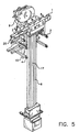
- Figs. 1 and 2 are perspective diagrammatic views taken from different directions of an embodiment of the present invention.
- Figs. 3-7 are perspective diagrammatic views of various components of the invention shown in Figs. 1 and 2.
- Fig. 8 is a diagrammatic view of
- Fig. 9 is a block diagram of the computed radiography system including present invention.
- computed radiography utilizes the principle that exposure of the storage phosphor to a radiographic image produces a corresponding latent image in the storage phosphor. If the storage phosphor is raster scanned (e.g., by means of laser) with light of a first wavelength, the latent image will be emitted as a light image at a second wavelength. The light emitted image is converted into an electronic (digital) radiographic image which can be stored, processed, displayed, and used to produce a hardcopy (film, paper) radiographic image.
- x-ray source 100 irradiates object of interest 102 (such as a body part) to produce a radiographic image which exposes CR image plate 104.
- the latent radiographic image stored in plate 104 is read out by CR reader 106 which subsequently erases plate 104 so that it can be reused.
- the read out image is converted into an electronic radiographic image 108 by reader 106.
- the electronic (digital) radiographic 108 image can be processed to enhance the image, archived for later use, displayed on a display monitor, transmitted to a remote location and/or used to produce a hard copy print (film, paper).
- FIGs. 1 and 7 there are shown perspective diagrammatic views of the present invention.
- the components shown are housed in an enclosed housing (not shown) and are only shown to the extent necessary to disclose the present invention. Many other components are not shown that are combined with the shown components to produce commercial computed radiography equipment.
- Cassette shell 11 is shown positioned at loading and unloading station 52.
- the CR cassette shell 1 1/image plate 16 can be of the type disclosed in U.S. Patent 5,861,631, issued January 19, 1999, inventors Wendlandt, et al. As shown in Fig. 1 image plate 16 has been removed from cassette shell.
- Image plate 16 carries a storage phosphor which stores a latent radiographic image to be read out by reader 50.
- Reader 50 includes a cassette clamping and image plate unlatching assembly including cassette stop 13, clamp rollers 19, drive rollers 20, cassette drive motors 18 for driving rollers 20, light shutter mechanism 12, sled 14, cam 9, and intermediate plate 15.
- An extraction bar 1 engages lower cassette extrusion 7 to extract an image plate 16 from cassette shell 11 after it has been unlatched by hooks 8 (Fig. 5).
- a suitable cassette latching and unlatching mechanism is disclosed in U.S. Patent 5,954,469, issued September 21, 1999, inventors Ngo, et al.
- An image plate handling assembly includes extraction bar 1, mounted for vertical movement on slide 6 and driven by screw and nut device 17, image plate guides 2, scan line rollers 3, erase line rollers 4, collector nose piece 5.
- Extrusion bar 1 includes a bar code scanner 25 (Fig. 5) for scanning a bar code on extrusion 7.
- the bar code can include plate dimensions, storage phosphor sensitometry, cassette ID number, etc.
- An erase station 54 includes a bank of lights (not shown) for erasing any residual image in image plate 16 after it has been scanned.
- the vertical scanning section consists of the cassette clamping device (Fig. 1) which is described in the following section, an extraction bar (1 ), a constant velocity slow scan motor (24),the plate guides ( 2), and the support rollers for the scan line (3), the movable collector nose piece (5), and the erase line rollers ( 4).
- the roller clamping device which could also be a pneumatic clamp or a mechanical clamp, holds the cassette relative to the extraction bar (1) as it is being unlatched and scanned. It is described in detail below.
- the surface of the extraction bar (1) is tilted at a slight angle to always tip the plate towards the plate guides (2) and the scan line rollers (3).
- the springs inside the extraction bar (1) are sized such that the plate is held against the bar with enough force to overcome bumps to the outside of the unit.
- the slow scan motor ( 24) is actuated and the scan process begins.
- the slow scan nut has a preload which takes all back lash out of the system. This combination is critical so the extraction bar (1) does not " fall " suddenly causing banding on the image.
- the extraction bar (1) pushes the plate guides (2) out of the path as the plate first exits the cassette.
- the guides then begin to support the plate after the extraction bar (1) passes.
- the plate guides (2) lift the plate slowly off the cassette shell (11) to eliminate the effect of rubbing surfaces inside the cassette during scanning.
- the collector nose piece (5) is actuated into place by a solenoid after the extraction bar (1) passes.
- the laser is then actuated and the scanning of the plate begins.
- linear cams (10) slowly bring the scan line rollers (3) into position. These rollers support the plate as it exits the cassette, and transitions off the plate guides (2).
- the purpose of the scan line rollers (3) is to support the plate at the scan line.
- the plate guides (2) could not do this because of the requirement for them to be close to the cassette entrance. It is critical to support the plate at the scan line to avoid large collector to plate changes in spacing due to plate flatness tolerances.
- the erase line rollers (4) cam in to support the plate during erase. They are not critical and could be simple stationary skids to ensure the shorter plates do not bind on the scan line rollers (3) when the plate is returned to the cassette.
- the cycle is reversed after the erase.
- the return speed of the extraction bar (1) is faster to reduce overall cycle time.
- the collector nose piece (5) is retracted, and the plate guides (2) act to ensure that the plate enters the cassette properly without binding.
- All components are linked together on a central casting to allow tolerances between subsystems to be minimized.
- the cassette shell (11) extract the image plate 16, and scan while removing the image plate 16 all of the subsystems must be located carefully relative to one another.
- the optical casting provides a frame structure that accomplishes this objective and minimizes tolerances.
- This concept is unique in that by scanning as the plate is extracted from the cassette in the vertical orientation the overall system size is significantly reduced. This is very important to hospitals which need to conserve space in the exam room area.
- the cam (9) and unlatching mechanism performs all of the motions required to clamp the cassette, unlatch the cassette, light seal, and hold the plate to the extraction bar (1).
- the cam (9) motion is accomplished by an inner and outer profile.
- the inner profile is a continuous slot engaged by a cam follower which moves the sled (14) forward and backward which clamps the cassette, actuates the light shutter mechanism (12), and unlatches the cassette.
- the outer peripheral profile operates the hooks (8) in the extraction bar (1) through a cam follower lineage. The operation is as follows:
- a cassette is ready for loading in the direction of arrow 70.
- the cam (9) is indexed to position #1. As the cam (9) makes this move the sled ( 14) is moved forward over plate 15 paralled to cassette 60 which causes the drive rollers (20) to move into position and "pinch” the cassette. Pinch is enough to drive the cassette 60 into position on the extraction bar.
- the drive rollers (20) are moved inward by a "ramp” located under the each roller so when the sled ( 14) moves ahead the drive roller (20) is indexed perpendicular to the sled ( 14) motion (Fig. 8) towards cassette 60.
- the cassette 60 is then driven into cassette stops (13) by the cassette drive rollers 20 driven by motors (18).
- the CAM (9) is indexed to position #2.
- the outside profile through the cam follower linkage raises the hooks (8) first.
- the inside profile of CAM 9 through cam follower moves the sled (14) ahead to unlatch the cassette latch.
- the clamping force is also increased on the cassette shell (11) as the drive rollers (20) finish the travel up the ramps and press the cassette shell (11) against the clamp rollers (19)
- Rollers 19 are made of a high durometer rubber or steel to locate the cassette shell (11).
- another "ramp” actuates a light shutter mechanism (12) to seal light around the back side of the cassette.
- the outside profile then lowers and releases the hooks ( 8).
- the lower cassette extrusion ( 7) holding the image plate (16) is now attached to the extraction bar (1).
- the scan cycle is then performed.
- the CAM (9) After scanning the CAM (9) is indexed to position #3. As the CAM (9) moves to position #3 the outside profile raises the hooks ( 8) in the extraction bar (1), the inner profile moves the cassette sled ( 14) backwards to relatch the cassette and ease the clamping force on the shell. The outside profile then lowers the hooks ( 8) down below the surface of the extraction bar (1).
- the cassette drive rollers (20) push the cassette 60 out of the unit and then the CAM (9) is indexed back to the home position. As the CAM (10) moves to the home position the inside profile moves the cassette sled ( 14) back and removes the pinch from the cassette shell (11).
Description
- This invention relates in general to computed radiography imaging systems and relates more particularly to a computed radiography imaging system in which exposed imaging plates are scanned while moved in a vertical direction.
- Conventional film/screen radiography uses radiographic films which are not reusable. Computed radiography solves this problem by using reusable storage phosphor imaging plates, that can be exposed, read out, erased, and reused many times. Some computed radiography systems are flexible storage phosphor imaging plates which can be degraded through contact of the storage phosphor layer with plate handling rollers and the like. Another computed radiography system uses rigid storage phosphor imaging plates where plate handling mechanisms do not contact the storage phosphor layer. Although an improvement over systems using flexible imaging plates, the horizontal reading and erase path of such a system results in a computed radiography reader which is bulkier and slower than may be desirable. There is thus a need for a computed radiography system that is compact in size, has increased image plate throughput, and eliminate degradation of the storage phosphor due to the excessive handling.
- U.S. Patent 5,340,995, discloses a scanner for a storage phosphor cassette including a rigid base plate and cover. The cassette sequentially transported in a vertical orientation to a cover removal separating station, a storage phosphor plate scanning station, an erasing station and a cassette reassembly station. U.S. Patents 4,777,373 and 5,954,469 discloses storage phosphor apparatus including motor driven screw assembles.
- According to a feature of the present invention there is provided:
- A computed radiography (CR) reader comprising:
- An image plate loading and unloading station for receiving in a vertical orientation a CR cassette including a light tight cassette shell and an image plate supported by an extrusion closing off said shell, said image plate storing a latent radiographic image;
- a scanning station located below said loading and unloading station at which said image plate is scanned; and an image plate transport assembly for removing said image plate from said cassette shell and for vertically transporting said image plate past said scanning station while said image plate is being removed from said cassette.
- 1. The computed radiography system is compact in size.
- 2. The vertically oriented computed radiography system has increased image plate throughput compared to horizontally oriented systems.
- 3. Degradation of storage phosphor layer is minimized.
-
- Figs. 1 and 2 are perspective diagrammatic views taken from different directions of an embodiment of the present invention.
- Figs. 3-7 are perspective diagrammatic views of various components of the invention shown in Figs. 1 and 2.
- Fig. 8 is a diagrammatic view of
- Fig. 9 is a block diagram of the computed radiography system including present invention.
- The invention has been described in detail with particular reference to certain preferred embodiments thereof, but it will be understood that variations and modifications can be effected within the scope of the invention as claimed.
- Referring now to Fig. 9, there will be described a generic computed radiography system. In general, computed radiography utilizes the principle that exposure of the storage phosphor to a radiographic image produces a corresponding latent image in the storage phosphor. If the storage phosphor is raster scanned (e.g., by means of laser) with light of a first wavelength, the latent image will be emitted as a light image at a second wavelength. The light emitted image is converted into an electronic (digital) radiographic image which can be stored, processed, displayed, and used to produce a hardcopy (film, paper) radiographic image.
- As shown in Fig. 9,
x-ray source 100 irradiates object of interest 102 (such as a body part) to produce a radiographic image which exposesCR image plate 104. The latent radiographic image stored inplate 104 is read out by CR reader 106 which subsequently erasesplate 104 so that it can be reused. The read out image is converted into an electronicradiographic image 108 by reader 106. The electronic (digital) radiographic 108 image can be processed to enhance the image, archived for later use, displayed on a display monitor, transmitted to a remote location and/or used to produce a hard copy print (film, paper). - Referring now to Figs. 1 and 7, there are shown perspective diagrammatic views of the present invention. The components shown are housed in an enclosed housing (not shown) and are only shown to the extent necessary to disclose the present invention. Many other components are not shown that are combined with the shown components to produce commercial computed radiography equipment.
- As shown, a CR cassette, 60 including a five
sided shell 11 and animage plate 16 cantilevered fromcassette extrusion 7, is loaded vertically intoCR reader 50.Cassette shell 11 is shown positioned at loading and unloadingstation 52. TheCR cassette shell 1 1/image plate 16 can be of the type disclosed in U.S. Patent 5,861,631, issued January 19, 1999, inventors Wendlandt, et al. As shown in Fig. 1image plate 16 has been removed from cassette shell.Image plate 16 carries a storage phosphor which stores a latent radiographic image to be read out byreader 50. -
Reader 50 includes a cassette clamping and image plate unlatching assembly includingcassette stop 13,clamp rollers 19,drive rollers 20,cassette drive motors 18 fordriving rollers 20,light shutter mechanism 12,sled 14, cam 9, andintermediate plate 15. Anextraction bar 1 engageslower cassette extrusion 7 to extract animage plate 16 fromcassette shell 11 after it has been unlatched by hooks 8 (Fig. 5). A suitable cassette latching and unlatching mechanism is disclosed in U.S. Patent 5,954,469, issued September 21, 1999, inventors Ngo, et al. - An image plate handling assembly includes
extraction bar 1, mounted for vertical movement onslide 6 and driven by screw andnut device 17,image plate guides 2,scan line rollers 3,erase line rollers 4,collector nose piece 5.Extrusion bar 1 includes a bar code scanner 25 (Fig. 5) for scanning a bar code onextrusion 7. The bar code can include plate dimensions, storage phosphor sensitometry, cassette ID number, etc. - Not shown are the laser scanning assembly and light collector located in the region of
line scan rollers 3. These components are well known and can be of the type disclosed in U.S. Patent 5,541,421, issued July 30, 1996, inventors Brandt, et al. - An
erase station 54 includes a bank of lights (not shown) for erasing any residual image inimage plate 16 after it has been scanned. - Operation of these components of
reader 50 are as follows with reference to Figs. 1-8. - The vertical scanning section consists of the cassette clamping device (Fig. 1) which is described in the following section, an extraction bar (1 ), a constant velocity slow scan motor (24),the plate guides ( 2), and the support rollers for the scan line (3), the movable collector nose piece (5), and the erase line rollers ( 4).
- The roller clamping device which could also be a pneumatic clamp or a mechanical clamp, holds the cassette relative to the extraction bar (1) as it is being unlatched and scanned. It is described in detail below.
- The extraction bar (1) and hooks ( 8) grip the lower cassette extrusion ( 7) which is attached to the image plate (16). The action of the cam (9) unlatching mechanism unlatches the cassettes with the hooks (8) in the extraction bar (1) and locks the image plate (16) onto the bar. The surface of the extraction bar (1) is tilted at a slight angle to always tip the plate towards the plate guides (2) and the scan line rollers (3). The springs inside the extraction bar (1) are sized such that the plate is held against the bar with enough force to overcome bumps to the outside of the unit.
- To begin the scanning process the slow scan motor ( 24) is actuated and the scan process begins. The slow scan nut has a preload which takes all back lash out of the system. This combination is critical so the extraction bar (1) does not " fall " suddenly causing banding on the image.
- The extraction bar (1) pushes the plate guides (2) out of the path as the plate first exits the cassette. The guides then begin to support the plate after the extraction bar (1) passes. The plate guides (2) lift the plate slowly off the cassette shell (11) to eliminate the effect of rubbing surfaces inside the cassette during scanning. As the plate moves toward the scan line the collector nose piece (5) is actuated into place by a solenoid after the extraction bar (1) passes. The laser is then actuated and the scanning of the plate begins. As the extraction bar (1) continues down during scanning, linear cams (10) slowly bring the scan line rollers (3) into position. These rollers support the plate as it exits the cassette, and transitions off the plate guides (2). The purpose of the scan line rollers (3) is to support the plate at the scan line. The plate guides (2) could not do this because of the requirement for them to be close to the cassette entrance. It is critical to support the plate at the scan line to avoid large collector to plate changes in spacing due to plate flatness tolerances. After the scan is completed the erase line rollers (4) cam in to support the plate during erase. They are not critical and could be simple stationary skids to ensure the shorter plates do not bind on the scan line rollers (3) when the plate is returned to the cassette.
- The cycle is reversed after the erase. The return speed of the extraction bar (1) is faster to reduce overall cycle time. The collector nose piece (5) is retracted, and the plate guides (2) act to ensure that the plate enters the cassette properly without binding.
- All components are linked together on a central casting to allow tolerances between subsystems to be minimized. In order to properly hold the cassette shell (11), extract the
image plate 16, and scan while removing theimage plate 16 all of the subsystems must be located carefully relative to one another. The optical casting provides a frame structure that accomplishes this objective and minimizes tolerances. - This concept is unique in that by scanning as the plate is extracted from the cassette in the vertical orientation the overall system size is significantly reduced. This is very important to hospitals which need to conserve space in the exam room area.
- The cam (9) and unlatching mechanism performs all of the motions required to clamp the cassette, unlatch the cassette, light seal, and hold the plate to the extraction bar (1). The cam (9) motion is accomplished by an inner and outer profile. The inner profile is a continuous slot engaged by a cam follower which moves the sled (14) forward and backward which clamps the cassette, actuates the light shutter mechanism (12), and unlatches the cassette. The outer peripheral profile operates the hooks (8) in the extraction bar (1) through a cam follower lineage. The operation is as follows:
- A cassette is ready for loading in the direction of
arrow 70. The cam (9) is indexed toposition # 1. As the cam (9) makes this move the sled ( 14) is moved forward overplate 15 paralled tocassette 60 which causes the drive rollers (20) to move into position and "pinch" the cassette. Pinch is enough to drive thecassette 60 into position on the extraction bar. The drive rollers (20) are moved inward by a "ramp" located under the each roller so when the sled ( 14) moves ahead the drive roller (20) is indexed perpendicular to the sled ( 14) motion (Fig. 8) towardscassette 60. Thecassette 60 is then driven into cassette stops (13) by thecassette drive rollers 20 driven by motors (18). Once reaching the cassette stops (13) the CAM (9) is indexed toposition # 2. As the CAM (9) moves to position #2 the outside profile through the cam follower linkage raises the hooks (8) first. Then the inside profile of CAM 9 through cam follower moves the sled (14) ahead to unlatch the cassette latch. During this move the clamping force is also increased on the cassette shell (11) as the drive rollers (20) finish the travel up the ramps and press the cassette shell (11) against the clamp rollers (19)Rollers 19 are made of a high durometer rubber or steel to locate the cassette shell (11). At the same time another "ramp" actuates a light shutter mechanism (12) to seal light around the back side of the cassette. The outside profile then lowers and releases the hooks ( 8). The lower cassette extrusion ( 7) holding the image plate (16) is now attached to the extraction bar (1).
The scan cycle is then performed. - After scanning the CAM (9) is indexed to
position # 3. As the CAM (9) moves to position #3 the outside profile raises the hooks ( 8) in the extraction bar (1), the inner profile moves the cassette sled ( 14) backwards to relatch the cassette and ease the clamping force on the shell. The outside profile then lowers the hooks ( 8) down below the surface of the extraction bar (1). The cassette drive rollers (20) push thecassette 60 out of the unit and then the CAM (9) is indexed back to the home position. As the CAM (10) moves to the home position the inside profile moves the cassette sled ( 14) back and removes the pinch from the cassette shell (11).
The invention has the following advantages.
Claims (7)
- A computed radiography (CR) reader (50) comprising:characterised in that said image plate transport assembly includes an image plate extraction bar (1) which locks said image plate (16) by said extrusion (7) to said bar (1) and further includes a support assembly (2),(3) for supporting said support side of said plate (16) during said transport along said path, and in that said extraction bar (1) tilts said plate (16) against said support assembly (2), (3).an image plate loading and unloading station (52) for receiving in a vertical orientation a CR cassette (60) including a light tight cassette shell (11) and an image plate (16) supported by an extrusion (7) closing off said shell (11), said image plate(16) having a support side and an image storing side storing a latent radiographic image;a scanning station (3) located below said loading and unloading station (52) at which said image plate is scanned;an image plate transport assembly for removing said image plate (16) from said cassette shell (11) and for vertically transporting said image plate (16) along a path past said scanning station while said image plate(16) is being removed from said cassette (60);
- The reader of claim 1 wherein said support (2) assembly includes a first image plate support (2) for supporting said image plate (16) on said support side as it is removed completely from said cassette (60).
- The reader of claim 2 wherein said first image plate support includes spaced guides (2) located adjacent to said loading and unloading station (52) and adapted to support said image plate (16) on said support side out of contact with said cassette shell (11) as said image plate is removed from said cassette shell (11).
- The reader of claim 3 wherein said support assembly includes a first set of spaced rollers (3) located below said guides (2) for supporting said support side of said image plate (16) at said scanning station.
- The reader of claim 2 wherein said support assembly includes a second image plate support (4) located below said scanning station for supporting said support side of said image plate (16) during erasure after scanning has been completed.
- The reader of claim 5 wherein said second image plate support includes a second set of spaced rollers (4) for supporting said support side of said image plate (16).
- The reader of claim 1 wherein said image plate extraction bar (1) is mounted for movement on a vertical slide (6) and driven by a motor actuated screw and nut assembly (17).
Applications Claiming Priority (2)
| Application Number | Priority Date | Filing Date | Title |
|---|---|---|---|
| US443799 | 1982-11-22 | ||
| US09/443,799 US6437359B1 (en) | 1999-11-19 | 1999-11-19 | CR reader with vertical scanning |
Publications (2)
| Publication Number | Publication Date |
|---|---|
| EP1102118A1 EP1102118A1 (en) | 2001-05-23 |
| EP1102118B1 true EP1102118B1 (en) | 2004-03-17 |
Family
ID=23762254
Family Applications (1)
| Application Number | Title | Priority Date | Filing Date |
|---|---|---|---|
| EP00203929A Expired - Lifetime EP1102118B1 (en) | 1999-11-19 | 2000-11-08 | Computed radiography reader with vertical scanning |
Country Status (4)
| Country | Link |
|---|---|
| US (1) | US6437359B1 (en) |
| EP (1) | EP1102118B1 (en) |
| JP (1) | JP2001183765A (en) |
| DE (1) | DE60009008T2 (en) |
Families Citing this family (12)
| Publication number | Priority date | Publication date | Assignee | Title |
|---|---|---|---|---|
| ATE363671T1 (en) * | 2001-12-20 | 2007-06-15 | Agfa Gevaert Healthcare Gmbh | MEMORY FLUORESCENT FILM FOR X-RAY PHOTOGRAPHS |
| WO2004081867A2 (en) * | 2003-03-11 | 2004-09-23 | Orex Computed Radiography | Methods and apparatus for protecting imaging media from contaminants |
| WO2004102627A2 (en) * | 2003-05-08 | 2004-11-25 | Alara, Inc. | Method and apparatus for radiation image erasure |
| DE502004007904D1 (en) | 2004-09-22 | 2008-10-02 | Agfa Gevaert Healthcare Gmbh | Device for reading x-ray information stored in a storage phosphor plate |
| ATE405864T1 (en) * | 2004-09-22 | 2008-09-15 | Agfa Gevaert Healthcare Gmbh | DEVICE AND METHOD FOR READING X-RAY INFORMATION STORED IN A FLUORESCENT STORAGE PLATE |
| US7358519B2 (en) * | 2004-12-17 | 2008-04-15 | Carestream Health, Inc. | U-flow multicassette autoloader for a storage phosphor reader |
| US7368747B2 (en) * | 2004-12-17 | 2008-05-06 | Carestream Health, Inc. | Short U-flow multicassette autoloader for a storage phosphor reader |
| US7482613B2 (en) * | 2004-12-17 | 2009-01-27 | Carestream Health, Inc. | Multicassette autoloader for a storage phosphor reader |
| US7446331B2 (en) * | 2006-08-21 | 2008-11-04 | Carestream Health, Inc. | Apparatus for scanning stimulable phosphor medium |
| US7456419B2 (en) * | 2006-08-21 | 2008-11-25 | Carestream Health, Inc. | Radiation imaging cassette |
| US7504651B2 (en) * | 2006-08-21 | 2009-03-17 | Carestream Health, Inc. | Sheet scanning apparatus |
| JP5921511B2 (en) * | 2013-09-30 | 2016-05-24 | 富士フイルム株式会社 | Radiation image reading apparatus, radiation image reading program, and radiation image reading method |
Family Cites Families (10)
| Publication number | Priority date | Publication date | Assignee | Title |
|---|---|---|---|---|
| JPS6195339A (en) * | 1984-10-16 | 1986-05-14 | Fuji Photo Film Co Ltd | Radiation image information recording and reading device |
| US4904868A (en) * | 1987-08-19 | 1990-02-27 | Fuji Photo Film Co., Ltd. | Radiation image read-out apparatus and stimulable phosphor sheet composite member for the same |
| EP0522317A1 (en) * | 1991-07-11 | 1993-01-13 | Eastman Kodak Company | Cassette for x-ray storage phosphor plate |
| DE69311433T2 (en) * | 1992-04-21 | 1998-01-02 | Agfa Gevaert Nv | Scanning device for PSL radiography cassette |
| US5493128A (en) * | 1994-08-25 | 1996-02-20 | Eastman Kodak Company | Method and apparatus for indexing cassettes |
| US5541421A (en) | 1994-11-21 | 1996-07-30 | Eastman Kodak Company | Light collector having optically coated acrylic substrate |
| EP0747753B1 (en) * | 1995-06-06 | 2003-01-15 | Agfa-Gevaert | Scanning apparatus for PSL radiography with a cassette stacker |
| US5861631A (en) | 1997-05-23 | 1999-01-19 | Eastman Kodak Company | Storage phosphor cassette with improved durability |
| US5954469A (en) | 1997-09-23 | 1999-09-21 | Eastman Kodak Company | Extraction bar mechanism for storage phosphor reader |
| US6410933B1 (en) * | 1999-11-19 | 2002-06-25 | Eastman Kodak Company | CR reader with integrated control mechanism |
-
1999
- 1999-11-19 US US09/443,799 patent/US6437359B1/en not_active Expired - Fee Related
-
2000
- 2000-10-19 JP JP2000319263A patent/JP2001183765A/en active Pending
- 2000-11-08 DE DE60009008T patent/DE60009008T2/en not_active Withdrawn - After Issue
- 2000-11-08 EP EP00203929A patent/EP1102118B1/en not_active Expired - Lifetime
Also Published As
| Publication number | Publication date |
|---|---|
| JP2001183765A (en) | 2001-07-06 |
| DE60009008T2 (en) | 2004-10-21 |
| DE60009008D1 (en) | 2004-04-22 |
| EP1102118A1 (en) | 2001-05-23 |
| US6437359B1 (en) | 2002-08-20 |
Similar Documents
| Publication | Publication Date | Title |
|---|---|---|
| EP1102118B1 (en) | Computed radiography reader with vertical scanning | |
| EP1104892B1 (en) | CR reader with integrated control mechanism | |
| JPH0687118B2 (en) | Radiation image information recording / reading device | |
| JP2647231B2 (en) | Radiation image information reader | |
| EP0166512B1 (en) | Radiographic apparatus | |
| WO2006065488A1 (en) | Multicassette autoloader for a storage phosphor reader | |
| JPS6224239A (en) | Device for recording and reproducing radiation image information | |
| WO2006065415A1 (en) | U-flow multicassette autoloader for storage phosphor reader | |
| JPH01154041A (en) | Radiant ray diagnostic device | |
| JP2830974B2 (en) | Scanning apparatus for PSL radiography with scanning carriage and belt | |
| JP3825928B2 (en) | Radiation image information reader | |
| JPH0644130B2 (en) | Radiation image information recording / reading device | |
| JP3782899B2 (en) | Sheet body scanning method and apparatus | |
| US5990487A (en) | Stage plunger mechanism for storage phosphor reader | |
| JP2628407B2 (en) | Method and apparatus for reading information from a slidable sheet of a rim cassette | |
| JPS6199139A (en) | Recorder/reader for radiation picture information | |
| JP4283983B2 (en) | Method and apparatus for cleaning sheet recording medium | |
| US4928016A (en) | Magazine for accommodating recording medium for electron microscope | |
| JP2000275763A (en) | Cassette for stimulable phosphor sheet and its id recognition structure | |
| JP2000122196A (en) | Scanner for sheet-like recording medium | |
| JPH0578817B2 (en) | ||
| JPH01237642A (en) | Radiographic image information recording reader | |
| JPH01237643A (en) | Radiographic image information recording reader | |
| JPS6050529A (en) | Cassetteless radiation snapshot photographing device for accumulative phosphor sheet | |
| JPS61295937A (en) | Cassetteless snapshotting apparatus |
Legal Events
| Date | Code | Title | Description |
|---|---|---|---|
| PUAI | Public reference made under article 153(3) epc to a published international application that has entered the european phase |
Free format text: ORIGINAL CODE: 0009012 |
|
| AK | Designated contracting states |
Kind code of ref document: A1 Designated state(s): DE FR GB |
|
| AX | Request for extension of the european patent |
Free format text: AL;LT;LV;MK;RO;SI |
|
| 17P | Request for examination filed |
Effective date: 20011117 |
|
| AKX | Designation fees paid |
Free format text: DE FR GB |
|
| 17Q | First examination report despatched |
Effective date: 20020422 |
|
| GRAP | Despatch of communication of intention to grant a patent |
Free format text: ORIGINAL CODE: EPIDOSNIGR1 |
|
| GRAS | Grant fee paid |
Free format text: ORIGINAL CODE: EPIDOSNIGR3 |
|
| GRAA | (expected) grant |
Free format text: ORIGINAL CODE: 0009210 |
|
| AK | Designated contracting states |
Kind code of ref document: B1 Designated state(s): DE FR GB |
|
| REG | Reference to a national code |
Ref country code: GB Ref legal event code: FG4D |
|
| REF | Corresponds to: |
Ref document number: 60009008 Country of ref document: DE Date of ref document: 20040422 Kind code of ref document: P |
|
| ET | Fr: translation filed | ||
| PLBE | No opposition filed within time limit |
Free format text: ORIGINAL CODE: 0009261 |
|
| STAA | Information on the status of an ep patent application or granted ep patent |
Free format text: STATUS: NO OPPOSITION FILED WITHIN TIME LIMIT |
|
| 26N | No opposition filed |
Effective date: 20041220 |
|
| PGFP | Annual fee paid to national office [announced via postgrant information from national office to epo] |
Ref country code: GB Payment date: 20051004 Year of fee payment: 6 |
|
| PGFP | Annual fee paid to national office [announced via postgrant information from national office to epo] |
Ref country code: FR Payment date: 20051104 Year of fee payment: 6 |
|
| PGFP | Annual fee paid to national office [announced via postgrant information from national office to epo] |
Ref country code: DE Payment date: 20051130 Year of fee payment: 6 |
|
| PG25 | Lapsed in a contracting state [announced via postgrant information from national office to epo] |
Ref country code: DE Free format text: LAPSE BECAUSE OF THE APPLICANT RENOUNCES Effective date: 20060221 |
|
| GBPC | Gb: european patent ceased through non-payment of renewal fee |
Effective date: 20061108 |
|
| REG | Reference to a national code |
Ref country code: FR Ref legal event code: ST Effective date: 20070731 |
|
| PG25 | Lapsed in a contracting state [announced via postgrant information from national office to epo] |
Ref country code: GB Free format text: LAPSE BECAUSE OF NON-PAYMENT OF DUE FEES Effective date: 20061108 |
|
| PG25 | Lapsed in a contracting state [announced via postgrant information from national office to epo] |
Ref country code: FR Free format text: LAPSE BECAUSE OF NON-PAYMENT OF DUE FEES Effective date: 20061130 |