EP1104266B1 - Stent-graft-membrane and method of making same - Google Patents
Stent-graft-membrane and method of making same Download PDFInfo
- Publication number
- EP1104266B1 EP1104266B1 EP19990941182 EP99941182A EP1104266B1 EP 1104266 B1 EP1104266 B1 EP 1104266B1 EP 19990941182 EP19990941182 EP 19990941182 EP 99941182 A EP99941182 A EP 99941182A EP 1104266 B1 EP1104266 B1 EP 1104266B1
- Authority
- EP
- European Patent Office
- Prior art keywords
- layer
- graft
- membrane
- endoprosthesis
- stent
- Prior art date
- Legal status (The legal status is an assumption and is not a legal conclusion. Google has not performed a legal analysis and makes no representation as to the accuracy of the status listed.)
- Expired - Lifetime
Links
Images


Classifications
-
- A—HUMAN NECESSITIES
- A61—MEDICAL OR VETERINARY SCIENCE; HYGIENE
- A61F—FILTERS IMPLANTABLE INTO BLOOD VESSELS; PROSTHESES; DEVICES PROVIDING PATENCY TO, OR PREVENTING COLLAPSING OF, TUBULAR STRUCTURES OF THE BODY, e.g. STENTS; ORTHOPAEDIC, NURSING OR CONTRACEPTIVE DEVICES; FOMENTATION; TREATMENT OR PROTECTION OF EYES OR EARS; BANDAGES, DRESSINGS OR ABSORBENT PADS; FIRST-AID KITS
- A61F2/00—Filters implantable into blood vessels; Prostheses, i.e. artificial substitutes or replacements for parts of the body; Appliances for connecting them with the body; Devices providing patency to, or preventing collapsing of, tubular structures of the body, e.g. stents
- A61F2/82—Devices providing patency to, or preventing collapsing of, tubular structures of the body, e.g. stents
- A61F2/86—Stents in a form characterised by the wire-like elements; Stents in the form characterised by a net-like or mesh-like structure
- A61F2/90—Stents in a form characterised by the wire-like elements; Stents in the form characterised by a net-like or mesh-like structure characterised by a net-like or mesh-like structure
-
- A—HUMAN NECESSITIES
- A61—MEDICAL OR VETERINARY SCIENCE; HYGIENE
- A61F—FILTERS IMPLANTABLE INTO BLOOD VESSELS; PROSTHESES; DEVICES PROVIDING PATENCY TO, OR PREVENTING COLLAPSING OF, TUBULAR STRUCTURES OF THE BODY, e.g. STENTS; ORTHOPAEDIC, NURSING OR CONTRACEPTIVE DEVICES; FOMENTATION; TREATMENT OR PROTECTION OF EYES OR EARS; BANDAGES, DRESSINGS OR ABSORBENT PADS; FIRST-AID KITS
- A61F2/00—Filters implantable into blood vessels; Prostheses, i.e. artificial substitutes or replacements for parts of the body; Appliances for connecting them with the body; Devices providing patency to, or preventing collapsing of, tubular structures of the body, e.g. stents
- A61F2/02—Prostheses implantable into the body
- A61F2/04—Hollow or tubular parts of organs, e.g. bladders, tracheae, bronchi or bile ducts
- A61F2/06—Blood vessels
- A61F2/07—Stent-grafts
-
- A—HUMAN NECESSITIES
- A61—MEDICAL OR VETERINARY SCIENCE; HYGIENE
- A61F—FILTERS IMPLANTABLE INTO BLOOD VESSELS; PROSTHESES; DEVICES PROVIDING PATENCY TO, OR PREVENTING COLLAPSING OF, TUBULAR STRUCTURES OF THE BODY, e.g. STENTS; ORTHOPAEDIC, NURSING OR CONTRACEPTIVE DEVICES; FOMENTATION; TREATMENT OR PROTECTION OF EYES OR EARS; BANDAGES, DRESSINGS OR ABSORBENT PADS; FIRST-AID KITS
- A61F2/00—Filters implantable into blood vessels; Prostheses, i.e. artificial substitutes or replacements for parts of the body; Appliances for connecting them with the body; Devices providing patency to, or preventing collapsing of, tubular structures of the body, e.g. stents
- A61F2/82—Devices providing patency to, or preventing collapsing of, tubular structures of the body, e.g. stents
- A61F2/86—Stents in a form characterised by the wire-like elements; Stents in the form characterised by a net-like or mesh-like structure
- A61F2/88—Stents in a form characterised by the wire-like elements; Stents in the form characterised by a net-like or mesh-like structure the wire-like elements formed as helical or spiral coils
- A61F2/885—Stents in a form characterised by the wire-like elements; Stents in the form characterised by a net-like or mesh-like structure the wire-like elements formed as helical or spiral coils comprising a coil including a plurality of spiral or helical sections with alternate directions around a central axis
-
- A—HUMAN NECESSITIES
- A61—MEDICAL OR VETERINARY SCIENCE; HYGIENE
- A61F—FILTERS IMPLANTABLE INTO BLOOD VESSELS; PROSTHESES; DEVICES PROVIDING PATENCY TO, OR PREVENTING COLLAPSING OF, TUBULAR STRUCTURES OF THE BODY, e.g. STENTS; ORTHOPAEDIC, NURSING OR CONTRACEPTIVE DEVICES; FOMENTATION; TREATMENT OR PROTECTION OF EYES OR EARS; BANDAGES, DRESSINGS OR ABSORBENT PADS; FIRST-AID KITS
- A61F2/00—Filters implantable into blood vessels; Prostheses, i.e. artificial substitutes or replacements for parts of the body; Appliances for connecting them with the body; Devices providing patency to, or preventing collapsing of, tubular structures of the body, e.g. stents
- A61F2/02—Prostheses implantable into the body
- A61F2/04—Hollow or tubular parts of organs, e.g. bladders, tracheae, bronchi or bile ducts
- A61F2002/041—Bile ducts
-
- A—HUMAN NECESSITIES
- A61—MEDICAL OR VETERINARY SCIENCE; HYGIENE
- A61F—FILTERS IMPLANTABLE INTO BLOOD VESSELS; PROSTHESES; DEVICES PROVIDING PATENCY TO, OR PREVENTING COLLAPSING OF, TUBULAR STRUCTURES OF THE BODY, e.g. STENTS; ORTHOPAEDIC, NURSING OR CONTRACEPTIVE DEVICES; FOMENTATION; TREATMENT OR PROTECTION OF EYES OR EARS; BANDAGES, DRESSINGS OR ABSORBENT PADS; FIRST-AID KITS
- A61F2/00—Filters implantable into blood vessels; Prostheses, i.e. artificial substitutes or replacements for parts of the body; Appliances for connecting them with the body; Devices providing patency to, or preventing collapsing of, tubular structures of the body, e.g. stents
- A61F2/02—Prostheses implantable into the body
- A61F2/04—Hollow or tubular parts of organs, e.g. bladders, tracheae, bronchi or bile ducts
- A61F2/06—Blood vessels
- A61F2/07—Stent-grafts
- A61F2002/072—Encapsulated stents, e.g. wire or whole stent embedded in lining
-
- A—HUMAN NECESSITIES
- A61—MEDICAL OR VETERINARY SCIENCE; HYGIENE
- A61F—FILTERS IMPLANTABLE INTO BLOOD VESSELS; PROSTHESES; DEVICES PROVIDING PATENCY TO, OR PREVENTING COLLAPSING OF, TUBULAR STRUCTURES OF THE BODY, e.g. STENTS; ORTHOPAEDIC, NURSING OR CONTRACEPTIVE DEVICES; FOMENTATION; TREATMENT OR PROTECTION OF EYES OR EARS; BANDAGES, DRESSINGS OR ABSORBENT PADS; FIRST-AID KITS
- A61F2/00—Filters implantable into blood vessels; Prostheses, i.e. artificial substitutes or replacements for parts of the body; Appliances for connecting them with the body; Devices providing patency to, or preventing collapsing of, tubular structures of the body, e.g. stents
- A61F2/02—Prostheses implantable into the body
- A61F2/04—Hollow or tubular parts of organs, e.g. bladders, tracheae, bronchi or bile ducts
- A61F2/06—Blood vessels
- A61F2/07—Stent-grafts
- A61F2002/075—Stent-grafts the stent being loosely attached to the graft material, e.g. by stitching
-
- A—HUMAN NECESSITIES
- A61—MEDICAL OR VETERINARY SCIENCE; HYGIENE
- A61F—FILTERS IMPLANTABLE INTO BLOOD VESSELS; PROSTHESES; DEVICES PROVIDING PATENCY TO, OR PREVENTING COLLAPSING OF, TUBULAR STRUCTURES OF THE BODY, e.g. STENTS; ORTHOPAEDIC, NURSING OR CONTRACEPTIVE DEVICES; FOMENTATION; TREATMENT OR PROTECTION OF EYES OR EARS; BANDAGES, DRESSINGS OR ABSORBENT PADS; FIRST-AID KITS
- A61F2210/00—Particular material properties of prostheses classified in groups A61F2/00 - A61F2/26 or A61F2/82 or A61F9/00 or A61F11/00 or subgroups thereof
- A61F2210/0004—Particular material properties of prostheses classified in groups A61F2/00 - A61F2/26 or A61F2/82 or A61F9/00 or A61F11/00 or subgroups thereof bioabsorbable
-
- A—HUMAN NECESSITIES
- A61—MEDICAL OR VETERINARY SCIENCE; HYGIENE
- A61F—FILTERS IMPLANTABLE INTO BLOOD VESSELS; PROSTHESES; DEVICES PROVIDING PATENCY TO, OR PREVENTING COLLAPSING OF, TUBULAR STRUCTURES OF THE BODY, e.g. STENTS; ORTHOPAEDIC, NURSING OR CONTRACEPTIVE DEVICES; FOMENTATION; TREATMENT OR PROTECTION OF EYES OR EARS; BANDAGES, DRESSINGS OR ABSORBENT PADS; FIRST-AID KITS
- A61F2210/00—Particular material properties of prostheses classified in groups A61F2/00 - A61F2/26 or A61F2/82 or A61F9/00 or A61F11/00 or subgroups thereof
- A61F2210/0076—Particular material properties of prostheses classified in groups A61F2/00 - A61F2/26 or A61F2/82 or A61F9/00 or A61F11/00 or subgroups thereof multilayered, e.g. laminated structures
-
- A—HUMAN NECESSITIES
- A61—MEDICAL OR VETERINARY SCIENCE; HYGIENE
- A61F—FILTERS IMPLANTABLE INTO BLOOD VESSELS; PROSTHESES; DEVICES PROVIDING PATENCY TO, OR PREVENTING COLLAPSING OF, TUBULAR STRUCTURES OF THE BODY, e.g. STENTS; ORTHOPAEDIC, NURSING OR CONTRACEPTIVE DEVICES; FOMENTATION; TREATMENT OR PROTECTION OF EYES OR EARS; BANDAGES, DRESSINGS OR ABSORBENT PADS; FIRST-AID KITS
- A61F2250/00—Special features of prostheses classified in groups A61F2/00 - A61F2/26 or A61F2/82 or A61F9/00 or A61F11/00 or subgroups thereof
- A61F2250/0014—Special features of prostheses classified in groups A61F2/00 - A61F2/26 or A61F2/82 or A61F9/00 or A61F11/00 or subgroups thereof having different values of a given property or geometrical feature, e.g. mechanical property or material property, at different locations within the same prosthesis
- A61F2250/0023—Special features of prostheses classified in groups A61F2/00 - A61F2/26 or A61F2/82 or A61F9/00 or A61F11/00 or subgroups thereof having different values of a given property or geometrical feature, e.g. mechanical property or material property, at different locations within the same prosthesis differing in porosity
- A61F2250/0024—Special features of prostheses classified in groups A61F2/00 - A61F2/26 or A61F2/82 or A61F9/00 or A61F11/00 or subgroups thereof having different values of a given property or geometrical feature, e.g. mechanical property or material property, at different locations within the same prosthesis differing in porosity made from both porous and non-porous parts, e.g. adjacent parts
-
- A—HUMAN NECESSITIES
- A61—MEDICAL OR VETERINARY SCIENCE; HYGIENE
- A61F—FILTERS IMPLANTABLE INTO BLOOD VESSELS; PROSTHESES; DEVICES PROVIDING PATENCY TO, OR PREVENTING COLLAPSING OF, TUBULAR STRUCTURES OF THE BODY, e.g. STENTS; ORTHOPAEDIC, NURSING OR CONTRACEPTIVE DEVICES; FOMENTATION; TREATMENT OR PROTECTION OF EYES OR EARS; BANDAGES, DRESSINGS OR ABSORBENT PADS; FIRST-AID KITS
- A61F2250/00—Special features of prostheses classified in groups A61F2/00 - A61F2/26 or A61F2/82 or A61F9/00 or A61F11/00 or subgroups thereof
- A61F2250/0014—Special features of prostheses classified in groups A61F2/00 - A61F2/26 or A61F2/82 or A61F9/00 or A61F11/00 or subgroups thereof having different values of a given property or geometrical feature, e.g. mechanical property or material property, at different locations within the same prosthesis
- A61F2250/0028—Special features of prostheses classified in groups A61F2/00 - A61F2/26 or A61F2/82 or A61F9/00 or A61F11/00 or subgroups thereof having different values of a given property or geometrical feature, e.g. mechanical property or material property, at different locations within the same prosthesis differing in fibre orientations
-
- A—HUMAN NECESSITIES
- A61—MEDICAL OR VETERINARY SCIENCE; HYGIENE
- A61F—FILTERS IMPLANTABLE INTO BLOOD VESSELS; PROSTHESES; DEVICES PROVIDING PATENCY TO, OR PREVENTING COLLAPSING OF, TUBULAR STRUCTURES OF THE BODY, e.g. STENTS; ORTHOPAEDIC, NURSING OR CONTRACEPTIVE DEVICES; FOMENTATION; TREATMENT OR PROTECTION OF EYES OR EARS; BANDAGES, DRESSINGS OR ABSORBENT PADS; FIRST-AID KITS
- A61F2250/00—Special features of prostheses classified in groups A61F2/00 - A61F2/26 or A61F2/82 or A61F9/00 or A61F11/00 or subgroups thereof
- A61F2250/0058—Additional features; Implant or prostheses properties not otherwise provided for
- A61F2250/0096—Markers and sensors for detecting a position or changes of a position of an implant, e.g. RF sensors, ultrasound markers
- A61F2250/0098—Markers and sensors for detecting a position or changes of a position of an implant, e.g. RF sensors, ultrasound markers radio-opaque, e.g. radio-opaque markers
Definitions
- the present invention relates to a stent-graft-membrane for placement at a treatment site within a body vessel or organ to enhance and direct fluid flow therethrough and a method of making the same. More particularly, the invention relates to an implantable endoprosthesis such as a stent combined with a generally impermeable membrane layer and a permeable graft layer.
- the graft and the membrane provide biocompatibility with tissue at the treatment site and provide biocompatibility with fluid in the lumen.
- Document WO-A-98/11847 represents the most relevant state of the art.
- Intraluminal implantable endoprosthesis such as self expanding stents, grafts and stentgrafts are known and are, for example, shown in United States Patent Nos. B1 4,954,126; 5,116,360; 5,133,742; 5,591,226; 5,653,747; and 5,679,470.
- a covered stent is described in International Publication Number WO 94/24961.
- a polyurethane is described in United States Patent No. 4,810,749.
- a porous implantable material is described in United States Patent No. 4,475.972.
- a method of forming an implantable graft is described in United States Patent No. 4,738,740.
- United States Patent No. 5,061,275 entitled, Self-Expanding Prosthesis, discloses a resilient, elastic self-expanding prosthesis comprising a flexible tubular body.
- United States Patent No. 5,645,559 entitled, Multiple Layer Stent, discloses a radially self-expanding stent having multiple layers that includes a medial region and proximal and distal cuffs having diameters greater than the medial region diameter when the stent is in the relaxed state.
- a silicone coating circumscribes at least the medial region of the stent.
- United States Patent No. 5,718,159 entitled, Process for Manufacturing Three-Dimensional Braided Covered Stent, discloses a prosthesis having a flexible tubular three-dimensionally braided structure of metal or polymeric monofilaments, and polymeric multifilament yarns.
- United States Patent No. 5,755,774 entitled "Bistable Luminal Graft Endoprosthesis” discloses a luminal graft endoprosthesis or endovascular graft which is capable of dilation and support functions and suitable for the endoluminal repair of vascular lesions and the like.
- An expandable support or stent is combined with a tubular graft made of a material having two unstressed conditions to provide a combined stent-graft wherein the graft material is secured to either or both of the internal or external surfaces of the stent.
- United States Patent No. 5,534,287 entitled “Methods for Applying an Elastic Coating Layer on Stents” discloses a coated stent comprising a cylindrical wall formed by meshed wires and a covering layer of elastic material extending on a portion of its length, with an outer surface, and totally embracing the wire mesh.
- United States Patent No. 4,850,999 entitled “Flexible Hollow Organ” discloses a flexible hollow organ, especially a vascular prosthesis intended for implantation in the human or animal body parts.
- the hollow organ includes a flexible prosthetic tube serving for a throughflow of a medium or which consists of such a prosthetic tube.
- a wall of the prosthetic tube exhibits at least one braided hose of flexible, elastic threads produced as a hollow meshwork.
- a stent-graft is described in United States Patent Application Serial No. 08/640,253, entitled “Cobalt-Chromium-Molybdenum Alloy Stent and Stent Graft", filed April 30, 1996.
- a stent-graft is described in United States Patent Application Serial No. 08/993,985, entitled “Stent-Graft with Bioabsorbable Structural Support", filed December 18, 1997.
- a stent-graft is described in United States Patent Application Serial No.08/946,906 entitled “Stent-Graft with Braided Polymeric Sleeve", filed October 8, 1997.
- the present invention relates to a body compatible endoprosthesis, including:
- the present invention includes a process for making an implantable endoprosthesis, including:
- the stent-graft-membrane of the present invention has at least three layers and is intended for treatment of vascular lumens. non-vascular lumens or organs in the body.
- the three layers include a structural stent layer. a graft layer and a membrane layer.
- the three layers may be formed in different combinations of layers.
- the stent-graft-membrane may advantageously be used in a variety of medical applications including intravascular treatment of stenoses, aneurysms or fistulas; maintaining openings in the urinary, biliary, tracheobronchial, esophageal, renal tracts, vena cava filters; repairing abdominal aortic aneurysms; or repairing or shunting damaged or diseased organs.
- the invention relates to an implantable endoprosthesis including a first number of elongated members wound helically in a first common direction and crossing a second number of elongated members wound helically in a second common direction.
- the crossings of the first and second elongated members define an angle and form a generally tubular body having an inside surface, outside surface, ends and a middle portion.
- the first and second elongated members are braided in a braid pattern and are configured to be constrainable to a reduced diameter and self-expandable to an increased diameter.
- the tubular body is disposed at a treatment site in a body vessel or organ having body tissue.
- a passage extends in a longitudinal direction at least partially through the generally tubular body.
- the passage at least partially contains a fluid in the lumen and directs flow.
- One or more outside layers are disposed over or on at least a portion of the outside surface of the tubular body. An outermost layer of the one or more outside layers is biocompatible with the body tissue.
- One or more inside layers are disposed over or on at least a portion of the inside surface of the tubular body. An innermost layer of the one or more inside layers is biocompatible with the fluid in the passage. At least one of the one or more outside layers or the one or more inside layers are substantially impermeable to fluids.
- the inside layer or the outside layer may each include one or more layers.
- the one or more inside and outside layers may include one or more membrane layers having an average permeability ranging from about 0 cc/cm 2 /min.
- the outside layer may be a film or membrane made of silicone or polycarbonate urethane and the inside layer may be a graft made of braided PET.
- the inside layer may be ePTFE or PTFE.
- the implantable endoprosthesis may be designed to provide structural support to a body vessel for a period of time and substantially separate a first body fluid located outside the endoprosthesis from a second body fluid located in the passage.
- the implantable endoprosthesis may be disposed at a Transjugular Intrahepatic Portosystemic Shunt (TIPS) treatment site.
- TIPS Transjugular Intrahepatic Portosystemic Shunt
- the first fluid may include bile and the second fluid may include blood.
- the braided implantable endoprosthesis may include an opening defined by each end of the generally tubular body.
- the tubular body may be made of metal, plastic, bioabsorbable or other synthetic or natural materials.
- the tubular body may have a braid angle or filament crossing angle of between about 65 degrees and 155 degrees.
- the invention also relates to an implantable endoprosthesis including a first set of filaments each of which extends in a configuration along a center line and having a first common direction of winding.
- a second set of filaments each extends in a configuration along a center line and having a second common direction of winding.
- the first and second filaments form a stent.
- One or more membrane layers having a first average permeability are disposed over or on at least one of an inside, interstices, or outside surface of the stent or a graft.
- One or more graft layers having a second average permeability are disposed over or on at least an inside, interstices, or outside surface of the stent.
- the first and second set of filaments, and the one or more membrane layers and graft layers form a self expanding structure having one or more layers including an inside layer, middle layer, outside layer, embedded layers or combinations thereof, inside surface, outside surface, proximal end, distal end, and a lumen.
- the inside surface is selected or configured to be substantially biocompatible with a fluid flow through the body lumen and the outside surface is selected or configured to be substantially biocompatible with a body tissue.
- the first average permeability may be less than the second average permeability.
- the one or more membrane layers may have an average permeability ranging from about 0 cc/cm 2 /min.
- the one or more graft layers may have an average permeability ranging from about 50 cc/cm 2 /min. to about 5000 cc/cm 2 /min.
- the one or more graft layers may include polyethylene terephthalate (PET), expanded polytetrafluoroethylene (ePTFE), polycarbonate urethane (PCU), polyurethane (PU), or combinations thereof.
- the one or more membrane layers may include siloxane polymers, polyurethane polymers, polycarbonate urethanes, PTFE, ePTFE, or combinations thereof.
- the one or more membrane layers may be disposed between the graft and the stent.
- the one or more graft layers may be disposed between the membrane and the stent.
- the stent may be disposed between the one or more membrane layers and the one or more graft layers.
- the layers may be bonded with an adhesive.
- the stent may be made of poly (alpha-hydroxy acid), PGA, PLA, PLLA, PDLA, polycaprolactone, polydioxanone, polygluconate, polylactic acid-polyethylene oxide copolymers, modified cellulose, collagen, poly(hydroxybutyrate), polyanhydride, polyphosphoester, poly(amino acids), or combinations thereof.
- the filaments may include Elgiloy®, stainless steel, nitinol, drawn filled tube (DFT), platinum, tungsten, tantalum, or combinations thereof.
- the graft layers may include a plurality of interwoven fibers, mono-filaments, multi-filaments, or yarns.
- the membrane layers may include a film, sheet, or tube.
- the implantable endoprosthesis may substantially exclude a first fluid located outside the surface of the implantable endoprosthesis from reaching a second fluid located in the lumen.
- the inside layer may be made of a PET polymer.
- the outside layer may be made of a silicone elastomer.
- the silicone elastomer may be a coating.
- the outside layer may be made of a polymer that is resistant to fluid permeability or resistant to tissue ingrowth.
- the invention also relates to a method of making a stent-graft-membrane including: forming a first number of elongated members wound helically in a first common direction and crossing a second number of elongated members wound helically in a second common direction.
- the crossing of the first and second elongated members define an angle and form a generally tubular body having an inside surface, outside surface, ends and a middle portion.
- the first and second elongated members are braided in a braid pattern and are designed to be constrainable to a reduced diameter and self-expandable to an increased diameter.
- the tubular body is adapted to be disposed at a treatment site in at least one of a body vessel or organ having body tissue; forming a passage extending in a longitudinal direction at least partially through the generally tubular body.
- the passage is adapted to at least partially contain a fluid; forming one or more outside layers on at least a portion of the outside surface of the tubular body.
- An outermost layer of the outside layers is biocompatible with the body tissue; forming one or more inside layers on at least a portion of the inside surface of the tubular body.
- An innermost layer of the inside layers is biocompatible with the fluid in the passage. At least one of the outside layers or the inside layers is substantially impermeable to a fluid.
- the invention also relates to a method of making a stent-graft-membrane including: braiding bioabsorbable filaments to form a tubular braid.
- the braid having a braid angle; disposing the braid on a mandrel; annealing the braid for a predetermined time to form an annealed stent; removing the stent from the mandrel, the stent having a filament crossing angle; forming a graft having an average permeability ranging from about 50 cc/cm 2 /min. to about 5000 cc/cm 2 /min.
- the method of making a stent-graft-membrane may further include prior to the step of adhering, applying a thermoplastic adhesive, curable adhesive, or bioabsorbable polymer adhesive to a surface of the stent or to a surface of the graft.
- the invention also relates to an implantable endoprosthesis including a first number of elongated members wound helically in a first common direction and crossing a second number of elongated members wound helically in a second common direction.
- the crossing of the first and second elongated members define an angle and form a generally tubular body having an inside surface, outside surface, ends and a middle portion therebetween.
- the first and second elongated members are braided in a braid pattern and are configured to be constrainable to a reduced diameter and self-expandable to an increased diameter.
- the tubular body is adapted to be disposed at a treatment site in at least one of a body vessel or organ having body tissue.
- a passage extends in a longitudinal direction at least partially through the tubular body.
- the passage is adapted to at least partially contain a fluid.
- One or more outside layers are disposed over at least a portion of the outside surface of the tubular body. At least one of the outside layers is a membrane made of a silicone or a polycarbonate urethane material biocompatible with the body tissue.
- One or more inside layers are disposed over at least a portion of the inside surface of the tubular body. At least one of the inside layers is a graft made of braided PET material biocompatible with the fluid in the passage.
- the implantable endoprosthesis is configured such that at least one of the outside layers is substantially impermeable to a fluid and substantially separates a first body fluid located outside the endoprosthesis from a second body fluid located in the passage.
- a first end portion of the implantable endoprosthesis may be disposed in a portal vein and the other end portion of the implantable endoprosthesis may be disposed in a hepatic vein.
- a middle portion of the braided implantable endoprosthesis may be disposed in a liver.
- the first fluid may be bile and the second fluid may be blood.
- a preferred use includes placing the stent-graft-membrane through a liver.
- Transjugular Intrahepatic Portosystemic Shunt (TIPS) is formed by an intrahepatic shunt connection between the portal venous system and the hepatic vein for prophylaxis of variceal bleeding, in the treatment of portal hypertension and its complications.
- Portal hypertension causes blood flow to be forced backward, causing veins to enlarge, resulting in variceal bleeding.
- the stent-graft-membrane advantageously acts as a shunt to enable blood to flow through the liver to the hepatic vein.
- the shunt generally decompresses portal hypertension and allows veins to shrink to normal size, stopping the variceal bleeding.
- a method of using a stent-graft-membrane comprises the steps: identifying a treatment site; determining the tissue, organ or fluid at the treatment site that the inside surface and the outside surface of the stent-graft-membrane are to be associated with; determining one or more materials for the inside and outside surfaces of the stent-graft-membrane that are substantially biocompatible with the tissue, organ or fluid at the treatment site; providing a stent-graft-membrane.
- the stent-graft-membrane having a first number of elongated members wound helically in a first common direction and crossing a second number of elongated members wound helically in a second common direction.
- the crossing of the first and second elongated members defining an angle therebetween and forming a generally tubular body having an inside surface, outside surface, ends and a middle portion therebetween.
- the first and second elongated members are braided in a braid pattern and are configured to be constrainable to a reduced diameter and self-expandable to an increased diameter.
- the generally tubular body is adapted to be disposed at a treatment site in at least one of a body vessel or organ having body tissue.
- a passage extends in a longitudinal direction at least partially through the generally tubular body.
- the passage is adapted or configured to at least partially contain a fluid.
- One or more outside layers are disposed over or on at least a portion of the outside of the tubular body.
- An outermost layer of the one or more outside layers is substantially biocompatible with the body tissue.
- One or more inside layers are disposed over or on at least a portion of the inside of the tubular body.
- An innermost layer of the one or more inside layers is substantially biocompatible with the fluid in the passage.
- At least one of the one or more outside layers or the one or more inside layers are substantially impermeable to fluids; inserting the stent-graft-membrane in a delivery device; inserting the delivery device into a body and delivering the stent-graft-membrane and at least a portion of the delivery device to the treatment site; and deploying the stent-graft-membrane into a position at the treatment site.
- an implantable medical device such as a stent-graft-membrane
- each of the component materials be biocompatible with the host tissue.
- an implantable medical device should accomplish its intended functional purpose in the body, and should generally not cause an unfavorable reaction in the tissue with which it interacts.
- Biocompatibility requirements may vary for different components of an implantable device.
- the inside surface of the implant must be biocompatible with the blood flowing through the lumen.
- the outside surface of the implant must be biocompatible with the tissue of the blood vessel.
- the general purpose of the stent-graft-membrane is to maintain a shunt for blood flow between the portal and hepatic veins.
- Each component in the stent-graft-membrane has a function which contributes to the general purpose of the device.
- the functional requirement of the stent is to mechanically hold the liver tissue open to maintain the shunt lumen.
- the functional requirement of the outer membrane is to prevent any inter-mixing of the bile, which is produced by the liver, into the blood which is flowing through the shunt. Inter-mixing of bile and blood may cause the blood to form thrombus.
- the functional requirement of the inside graft is to provide an interface with the blood which advantageously improves the blood biocompatibilty of the implant.
- the stent, graft, or membrane layers may be substantially individual layers that are at least partially bonded together.
- the stent-graft-membrane may include a stent embedded in the membrane or the membrane embedded in the stent; the stent embedded in the graft or the graft embedded in the stent; and the membrane embedded in the graft or the graft embedded in the membrane. At least one of the stent, graft, or membrane may be embedded in the other.
- Each embodiment of the stent-graft-membrane may include a radiopaque tracer wire to make one or more portions more visible during fluoroscopy.
- Each embodiment of the stent-graft-membrane may include bare filaments at one or more end portions or middle portions.
- Figure 1 illustrates an embodiment of the stent-graft-membrane 20 with a stent layer 22 located on the outside, a graft layer 26 located in the middle, and a membrane layer 30 located on the inside.
- Figure 1A illustrates an end view of the stent-graft-membrane 20 in Figure 1.
- Figure 2 illustrates an embodiment of the stent-graft-membrane 20 having a stent layer 22 located on the outside, a membrane layer 30 located in the middle, and a graft layer 26 located on the inside.
- Figure 2A illustrates an end view of the stent-graft-membrane 20 of Figure 2.
- Figure 3 illustrates an embodiment of the stent-graft-membrane 20 having a graft layer 26 located on the outside, a stent layer 22 located in the middle, and a membrane layer 30 located on the inside.
- Figure 3A illustrates an end view of the stent-graft-membrane 20 of Figure 3.
- Figure 4 illustrates an embodiment of the stent-graft-membrane 20 having a graft layer 26 located on the outside, a membrane layer 30 located in the middle, and a stent layer 22 located on the inside.
- Figure 4A illustrates an end view of the stent-graft-membrane 20 of Figure 4.
- Figure 5 illustrates an embodiment of the stent-graft-membrane 20 having a membrane layer 30 located on the outside, a graft layer 26 located in the middle, and a stent layer 22 located on the inside.
- Figure 5A illustrates an end view of the stent-graft-membrane 20 of Figure 5.
- Figure 6 illustrates an embodiment of the stent-graft-membrane 20 having a membrane layer 30 located on the outside, a stent layer 22 located in the middle, and a graft layer 26 located on the inside.
- Figure 6A illustrates an end view of the stent-graft-membrane 20 of Figure 6.
- the stent is a tubular mesh including interbraided helically-wound filaments.
- the tubular mesh is capable of a reduction in diameter with a corresponding increase in length.
- the reduction in diameter facilitates the delivery of the endoprosthesis to the implant site by a deployment catheter.
- the filaments may include metal having a sufficiently high modulus of elasticity to provide elasticity to the braided structure.
- the metal structure is age hardened to augment the resiliency of the stent. This results in a self-expanding structure which opens to an expanded diameter when released from a constrained state.
- Stent filaments may be made of implantable grade medical stainless steels, Elgiloy®, Conichrome, Phynox, MP35N, nickel/titanium alloys, Nitinol, cobalt-based alloys, CoCrMo, Titanium alloys, titanium-zirconium-niobium alloys, titanium-aluminum-vanadium alloy known as TI-6A1-4V, drawn filled tube (DFT), platinum, tungsten, tantalum, or combinations thereof.
- implantable grade medical stainless steels Elgiloy®, Conichrome, Phynox, MP35N, nickel/titanium alloys, Nitinol, cobalt-based alloys, CoCrMo, Titanium alloys, titanium-zirconium-niobium alloys, titanium-aluminum-vanadium alloy known as TI-6A1-4V, drawn filled tube (DFT), platinum, tungsten, tantalum, or combinations thereof.
- Stent filaments may also be made of polymers, bioabsorbable polymers, PET, polypropylene, PEEK, HDPE, polysulfone, acetyl, PTFE, FEP, and polyurethane, or combinations thereof.
- Stent filaments may also be made of poly(alpha-hydroxy acid), PGA, PLA, PLLA, PDLA, polycarprolactone, polydioxanone, polygluconate, polylactic acid-polyethylene oxide copolymers, modified cellulose, collagen, poly(hydroxybutyrate), polyanhydride, polyphosphoester, poly(amino acides), or combinations thereof.
- Average diameters of the filaments may range from about 0.051mm (0.002 inches) to about 0.038mm (0.015 inches).
- the graft is designed to be compatible with the body tissue or the fluid that it contacts. For example, if the graft is placed on the outside of a stent and is intended for placement in an airway, the graft is made of a material that is compatible with the tissue on the inside of the airway. If the graft is placed on the inside of a stent and is intended for placement in a blood vessel, the graft is made of a material that is compatible with blood.
- a preferred embodiment of the graft includes a tubular mesh of interbraided polyethylene terephthalate (PET) yarns.
- PET polyethylene terephthalate
- This graft includes two sets of textile strands, helically wrapped in opposite directions around a mandrel in an intertwining pattern to produce a graft which behaves according to approximately the same axial lengthening/diametrical reduction relationship as the stent.
- Other possible graft structures may include woven or knitted textile grafts and spun-filament grafts.
- the graft generally has a lower permeability than the stent.
- Textile strands preferably are multifilament yarns, although they can be monofilaments.
- the textile strands range from about 10 denier to 400 denier.
- Individual filaments of the multifilament yarns can range from about 0.25 to about 10 denier.
- Permeability ranges from about 50 cc/cm 2 /min. to about 5000 cc/cm 2 /min. at about 16 x 10 3 pa (120mmHg) differential pressure.
- the graft layer may be made of spun polycarbonate urethane to create a tubular structure.
- the graft may have an average wall thickness between about 0.025mm (.001 inch) and about 0.25mm (.010 inch).
- Graft material may include PET such as Dacron, ePTFE, polyurethane, polycarbonate urethane, polypropylene, polyethylene such as Spectra, HDPE, silicone, PTFE, and polyolefins.
- PET such as Dacron, ePTFE, polyurethane, polycarbonate urethane, polypropylene, polyethylene such as Spectra, HDPE, silicone, PTFE, and polyolefins.
- the membrane is designed to limit permeability. Permeability is defined as the ability of fluids to flow through the wall of the stent-graft-membrane. A purpose of the membrane is to further restrict the flow of fluids through the wall of a stent or stent-graft.
- the membrane can be made by a number of different techniques and a number of different materials. Permeability ranges from about 0 cc/cm 2 /min. to about 100 cc/cm 2 /min. at 16 x 10 3 pa (120mmHg) differential pressure.
- Membrane materials may include siloxane polymers, polyurethane polymers, polycarbonate urethanes, PTFE or ePTFE.
- a membrane may be formed on a stent or stent-grant by dipping the stent or stent-graft into a solution including a polymer with a solvent.
- the membrane may become embedded in the stent or stent-graft and is generally not a discrete layer.
- the stent or stent-graft is then removed from the solution, forming a membrane on the stent or stent-graft.
- the solvent is evaporated from the membrane, and the polymer is cured, if a curable polymer such as silicone is used.
- the membrane layer may have a thickness between about 0.025mm (.001 inch) and about 0.25mm (.010 inch).
- a membrane may also be formed by impregnating a porous graft with a polymer.
- the polymer becomes integrated in the graft interstices, resulting in a graft-membrane which has substantially lower permeability than the graft starting material.
- a membrane may also be formed by providing a stent-grant having a stent on the inside layer and a braided PET graft on the outside layer.
- the stent-graft is placed over a mandrel which has an outer diameter similar to the inner diameter of the stent-graft.
- the ends of the mandrel are affixed in a machine which rotates the stent-graft and mandrel about a central axis.
- the stent-graft is sprayed with a solution of silicone in a volatile solvent such as tetrahydrofuran.
- a volume of approximately 10cc of silicone solution is sprayed intermittently over a period of approximately fifteen minutes onto the stem-graft.
- the sprayed stent-graft-membrane and mandrel are placed in an oven at 150°C for a period of thirty minutes to cure the silicone polymer.
- the stent, graft and membrane composite is substantially impermeable.
- An additional graft layer may be bonded on the inside or outside of the stent-graft-membrane depending on biocompatibility needs. For example, if a silicone has embedded in the graft. the silicone may extend to the inside surface where blood flow occurs. In that case, it may be desirable to add a PET braided graft on the inside for biocompatibilty purposes.
- a stent-graft-membrane 20 was made by spraying silicone on a stent-graft.
- a 10 mm diameter and 50 mm length stent-graft comprising an Elgiloy stent and braided PET graft were bonded together with polycarbonate urethane and placed over a 10mm diameter mandrel that was first sprayed with a TFE release agent.
- the mandrel and the stent-graft were placed on a rotational fixture and the motor was turned on to rotate the stent-graft.
- the stent-graft was coated with a volume of approximately 10cc of a 6% solid silicone solution.
- the silicone solution was applied with an airbrush from a distance of approximately 8-10 cm.
- the solution was applied intermittently over the course of approximately 15 minutes to allow the THF and Xylene solvents to evaporate from the stent-graft surface as it was sprayed in order to prevent the graft from becoming too wet.
- the silicone was applied, the mandrel and stent-graft-membrane were placed in an oven at 150°C for a period of 30 minutes to cure the silicone polymer. After 30 minutes, the stent-graft-membrane was removed from the oven and allowed to cool.
- Alternative methods of making the stent-graft-membrane 20 in Example I can include: spraying a stent and graft assembly that has not been bonded together with a polymer in solution; spraying the stent-graft with polycarbonate urethane; using a non-coated graft on the inside of stent; or using a mandrel coated with PTFE.
- a first number of elongated members 22a are wound in a helical pattern in a first common direction and cross a second number of elongated members 22b wound in a helical pattern in a second common direction.
- the crossing point 23 of the first and second elongated members 22a, 22b define an angle ⁇ .
- the elongated members 22a, 22b form a stent 20 having an inside surface, outside surface, ends and a middle portion.
- the elongated members 22a, 22b are braided in a braid pattern and are constrainable to a reduced diameter and are self-expandable to an increased diameter.
- An outside layer such as graft layer 26 or membrane layer 30 is disposed over or on at least a portion of the outside surface of the stent 22.
- the outermost layer is biocompatible with the body tissue.
- An inside layer such as graft layer 26 or membrane layer 30 is disposed over or on at least a portion of the inside surface of the stent 22.
- the innermost layer is biocompatible with the fluid in the passage 38.
- the membrane layer 30 that is located outside or inside the stent 22 is substantially impermeable to fluids. Average permeability of a membrane layer 30 ranges from about 0 cc/cm 2 /min. to about 100 cc/cm 2 /min.
- a passage 38 extends in a longitudinal direction at least partially through the stent-graft-membrane 20. The passage 38 is for channeling fluid and for providing a flow direction for the fluid in a vessel or organ.
- stent-graft-membrane 20 includes a first set of filaments 22a which extend in a configuration along a center line and have a first common direction of winding.
- a second set of filaments 22b extend in a configuration along a center line and have a second common direction of winding.
- the first and second filaments 22a, 22b form a stent 22.
- a membrane layer 30 with a first average permeability is disposed on the inside or the outside of the stent 22.
- a graft layer 26 with a second average permeability is disposed over or on the inside or the outside of the stent 22.
- the first and second set of filaments 22a, 22b, membrane layers 30, and graft layers 26 form a self expanding structure having an inside layer, outside layer, and a lumen 38.
- the membrane layer 30 may be disposed between the graft 26 and the stent 22.
- the graft layers 26 may be disposed between the membrane 30 and the stent 22.
- the stent 22 may be outside or inside the graft 26 and membrane 30.
- the layers 22, 26, 30 may be bonded by an adhesive.
- the inside layer is biocompatible with a fluid flow through the body lumen and the outside layer is biocompatible with body tissue.
- the membrane layer 30 has an average permeability ranging from about 0 cc/cm 2 /min. to about 100 cc/cm 2 /min.
- the graft layer 26 may include a plurality of interwoven fibers, mono-filaments, multi-filaments, or yarns.
- the graft layer 26 may include polyethylene terephthalate (PET), expanded polytetrafluoroethylene (ePTFE), polycarbonate urethane (PCU), polyurethane (PU), or combinations thereof.
- the membrane layer 30 may include siloxane polymers, polyurethane polymers, polycarbonate urethanes, PTFE, ePTFE, or combinations thereof.
- the membrane layers 30 may be a film, sheet, or tube.
- the stent-graft-membrane 20 substantially excludes a first fluid located outside the stent-graft-membrane 20 from reaching a second fluid located in the lumen 38.
- the stent-graft-membrane includes one or more outside layers disposed over or on the outside of the stent 22.
- the outside layer is a membrane 30 made of a silicone or a polycarbonate urethane material that is biocompatible with the body tissue.
- One or more inside layers are disposed over or on the inside of the stent 22.
- the inside layer is a graft 26 made of braided PET material biocompatible with the fluid in the passage 38.
- the graft 26 may be braided, spun or spray-cast.
- the outside layers are substantially impermeable to a fluid and substantially separate a first body fluid located outside the stent-graft-membrane 20 from a second body fluid located in the passage 38.
- Figure 7 illustrates an end view of a stent-graft-membrane 20 in which the inside layer is a graft layer 26 made of braided PET, the middle layer is a braided stent 22, and the outer layer is a membrane layer 30 made of silicone.
- the composite layers include three-layers 22, 26, 30 which may be bonded together under heat and pressure so that the membrane layer 30 conforms to the profile of the stent layer 22 and graft layer 26 as shown.
- Figure 8 illustrates a stent-graft-membrane 20.
- the inside layer is a graft layer 26 made of braided PET.
- the middle layer is a braided stent 22.
- the outside layer is a graft layer 26 made of braided PET which has been impregnated with silicone to create a substantially impermeable graft/membrane layer 26,30 as described in Example 1.
- FIG. 9 illustrates a stent-graft-membrane 20 with an exposed middle portion 20b.
- Figure 10 illustrates a fully covered stent-graft-membrane 20.
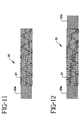
- Figure 11 illustrates a stent-graft-membrane 20 with one exposed end portion 20a.
- Figure 12 illustrates a stent-graft-membrane 20 with two exposed end portions 20a, 20c.
- FIG 13 illustrates a TIPS treatment site 50.
- Figure 14 illustrates a stent-graft-membrane 20 disposed at a TIPS treatment site 50.
- the stent-graft-membrane 20 may be used for creation or revision of a transjugular intrahepatic portosystemic shunt (TIPS).
- TIPS transjugular intrahepatic portosystemic shunt
- the stent-graft-membrane 20 substantially separates a first fluid such as bile located outside the stent-graft-membrane 20 from a second fluid such as blood located and channeled in the passage 38.
- One end portion of the stent-graft-membrane 20 is disposed in a portal vein, a middle portion of the stent-graft-membrane 20 is disposed in a liver, and the other end portion is disposed in a hepatic vein.
- a TIPS treatment method includes puncturing the right internal jugular vein; advancing a wire into the IVC followed by a 40cm, 9-10F sheath with a hemostatic valve; catheterizing the hepatic vein; using a stiff wire to introduce the needle set; positioning the needle in the hepatic vein and retracting the sheath to reveal the needle tip; advancing the needle through the liver and puncturing the portal vein; injecting contrast to identify the vascular structure; advancing a guidewire through the needle; the wire should enter the portal vein; removing the needle; introducing a catheter; measuring portal pressure; performing a portal venogram; exchanging the catheter for a balloon; dilating the parenchymal tract; advancing the vascular sheath into the tract and removing the balloon; introducing the stent-graft-membrane into the portal vein; positioning and deploying the stent-graft-membrane; exchanging the delivery sheath for a 5Fr, 8mm balloon; expanding the stent-graft
Abstract
Description
- The present invention relates to a stent-graft-membrane for placement at a treatment site within a body vessel or organ to enhance and direct fluid flow therethrough and a method of making the same. More particularly, the invention relates to an implantable endoprosthesis such as a stent combined with a generally impermeable membrane layer and a permeable graft layer. The graft and the membrane provide biocompatibility with tissue at the treatment site and provide biocompatibility with fluid in the lumen. Document WO-A-98/11847 represents the most relevant state of the art.
- Intraluminal implantable endoprosthesis such as self expanding stents, grafts and stentgrafts are known and are, for example, shown in United States Patent Nos. B1 4,954,126; 5,116,360; 5,133,742; 5,591,226; 5,653,747; and 5,679,470. A covered stent is described in International Publication Number WO 94/24961. A polyurethane is described in United States Patent No. 4,810,749. A porous implantable material is described in United States Patent No. 4,475.972. A method of forming an implantable graft is described in United States Patent No. 4,738,740.
- United States Patent No. B1 4,655,771, entitled, Prosthesis Comprising Expansible or Contractile Tubular Body, discloses a prosthesis comprising a flexible tubular body for transluminal implantation.
- United States Patent No. 5,061,275, entitled, Self-Expanding Prosthesis, discloses a resilient, elastic self-expanding prosthesis comprising a flexible tubular body.
- United States Patent No. 5,645,559, entitled, Multiple Layer Stent, discloses a radially self-expanding stent having multiple layers that includes a medial region and proximal and distal cuffs having diameters greater than the medial region diameter when the stent is in the relaxed state. A silicone coating circumscribes at least the medial region of the stent.
- United States Patent No. 5,718,159, entitled, Process for Manufacturing Three-Dimensional Braided Covered Stent, discloses a prosthesis having a flexible tubular three-dimensionally braided structure of metal or polymeric monofilaments, and polymeric multifilament yarns.
- United States Patent No. 5, 741,333, entitled "Self-Expanding Stent for a Medical-Device to be Introduced into a Cavity of a Body", discloses a self-expanding stent
- United States Patent No. 5,755,774 entitled "Bistable Luminal Graft Endoprosthesis" discloses a luminal graft endoprosthesis or endovascular graft which is capable of dilation and support functions and suitable for the endoluminal repair of vascular lesions and the like. An expandable support or stent is combined with a tubular graft made of a material having two unstressed conditions to provide a combined stent-graft wherein the graft material is secured to either or both of the internal or external surfaces of the stent.
- United States Patent No. 5,534,287 entitled "Methods for Applying an Elastic Coating Layer on Stents" discloses a coated stent comprising a cylindrical wall formed by meshed wires and a covering layer of elastic material extending on a portion of its length, with an outer surface, and totally embracing the wire mesh.
- United States Patent No. 4,850,999 entitled "Flexible Hollow Organ" discloses a flexible hollow organ, especially a vascular prosthesis intended for implantation in the human or animal body parts. The hollow organ includes a flexible prosthetic tube serving for a throughflow of a medium or which consists of such a prosthetic tube. A wall of the prosthetic tube exhibits at least one braided hose of flexible, elastic threads produced as a hollow meshwork.
- A stent-graft is described in United States Patent Application Serial No. 08/640,253, entitled "Cobalt-Chromium-Molybdenum Alloy Stent and Stent Graft", filed April 30, 1996.
- A stent-graft is described in United States Patent Application Serial No. 08/993,985, entitled "Stent-Graft with Bioabsorbable Structural Support", filed December 18, 1997.
- A stent-graft is described in United States Patent Application Serial No.08/946,906 entitled "Stent-Graft with Braided Polymeric Sleeve", filed October 8, 1997.
- The present invention relates to a body compatible endoprosthesis, including:
- a tubular wall adapted to be deployed at a treatment site to contain and direct flow of a first fluid, said tubular wall including a tubular layer;
- the tubular wall further including a first graft layer formed of a graft material biocompatible with the first fluid;
- the tubular wall further including a membrane layer formed of a membrane material biocompatible with tissue at the treatment site; and
- the tubular wall further defining a fluid passage; characterised in that said tubular layer comprises structural mesh and in that said first graft layer has a first average permeability and is adapted for containing and directing flow of the first fluid in the passage when the tubular wall is so deployed; and
- the membrane layer substantially surrounds the graft layer, and has a second average permeability less than the first average permeability to further restrict flow of fluids through the wall, and thereby is adapted to prevent a second fluid, located outside the tubular wall when the tubular wall is so deployed, from reaching and intermixing with the first fluid in the passage.
-
- Also, the present invention includes a process for making an implantable endoprosthesis, including:
- providing a tubular mesh structure;
- forming a graft layer of a graft material with a first average permeability, and disposing the graft layer along an inside surface of the tubular mesh structure; and
- forming a membrane layer of a membrane material along an outside surface of the tubular mesh structure, with a second average permeability of the membrane layer being less than the first average permeability of the graft layer.
-
- The stent-graft-membrane of the present invention has at least three layers and is intended for treatment of vascular lumens. non-vascular lumens or organs in the body. The three layers include a structural stent layer. a graft layer and a membrane layer. The three layers may be formed in different combinations of layers. A need exists for a stent-graft-membrane of the present invention having layers with surfaces that are selected to be biocompatible with the tissue or fluid for which they are associated with while treating vessels or organs. Biocompatibility means that the implant is accepted by the host tissue and does not create an adverse biological response.
- The stent-graft-membrane may advantageously be used in a variety of medical applications including intravascular treatment of stenoses, aneurysms or fistulas; maintaining openings in the urinary, biliary, tracheobronchial, esophageal, renal tracts, vena cava filters; repairing abdominal aortic aneurysms; or repairing or shunting damaged or diseased organs.
- In sum, the invention relates to an implantable endoprosthesis including a first number of elongated members wound helically in a first common direction and crossing a second number of elongated members wound helically in a second common direction. The crossings of the first and second elongated members define an angle and form a generally tubular body having an inside surface, outside surface, ends and a middle portion. The first and second elongated members are braided in a braid pattern and are configured to be constrainable to a reduced diameter and self-expandable to an increased diameter. The tubular body is disposed at a treatment site in a body vessel or organ having body tissue. A passage extends in a longitudinal direction at least partially through the generally tubular body. The passage at least partially contains a fluid in the lumen and directs flow. One or more outside layers are disposed over or on at least a portion of the outside surface of the tubular body. An outermost layer of the one or more outside layers is biocompatible with the body tissue. One or more inside layers are disposed over or on at least a portion of the inside surface of the tubular body. An innermost layer of the one or more inside layers is biocompatible with the fluid in the passage. At least one of the one or more outside layers or the one or more inside layers are substantially impermeable to fluids. The inside layer or the outside layer may each include one or more layers. The one or more inside and outside layers may include one or more membrane layers having an average permeability ranging from about 0 cc/cm2/min. to about 100 cc/cm2/min. and/or one or more graft layers having an average permeability ranging from about 50 cc/cm2/min. to about 5000 cc/cm2/min. The outside layer may be a film or membrane made of silicone or polycarbonate urethane and the inside layer may be a graft made of braided PET. The inside layer may be ePTFE or PTFE. The implantable endoprosthesis may be designed to provide structural support to a body vessel for a period of time and substantially separate a first body fluid located outside the endoprosthesis from a second body fluid located in the passage. The implantable endoprosthesis may be disposed at a Transjugular Intrahepatic Portosystemic Shunt (TIPS) treatment site. At a TIPS treatment site, the first fluid may include bile and the second fluid may include blood. The braided implantable endoprosthesis may include an opening defined by each end of the generally tubular body. The tubular body may be made of metal, plastic, bioabsorbable or other synthetic or natural materials. The tubular body may have a braid angle or filament crossing angle of between about 65 degrees and 155 degrees.
- The invention also relates to an implantable endoprosthesis including a first set of filaments each of which extends in a configuration along a center line and having a first common direction of winding. A second set of filaments each extends in a configuration along a center line and having a second common direction of winding. The first and second filaments form a stent. One or more membrane layers having a first average permeability are disposed over or on at least one of an inside, interstices, or outside surface of the stent or a graft. One or more graft layers having a second average permeability are disposed over or on at least an inside, interstices, or outside surface of the stent. The first and second set of filaments, and the one or more membrane layers and graft layers form a self expanding structure having one or more layers including an inside layer, middle layer, outside layer, embedded layers or combinations thereof, inside surface, outside surface, proximal end, distal end, and a lumen. The inside surface is selected or configured to be substantially biocompatible with a fluid flow through the body lumen and the outside surface is selected or configured to be substantially biocompatible with a body tissue. The first average permeability may be less than the second average permeability. The one or more membrane layers may have an average permeability ranging from about 0 cc/cm2/min. to about 100 cc/cm2/min., and the one or more graft layers may have an average permeability ranging from about 50 cc/cm2/min. to about 5000 cc/cm2/min. The one or more graft layers may include polyethylene terephthalate (PET), expanded polytetrafluoroethylene (ePTFE), polycarbonate urethane (PCU), polyurethane (PU), or combinations thereof. The one or more membrane layers may include siloxane polymers, polyurethane polymers, polycarbonate urethanes, PTFE, ePTFE, or combinations thereof. The one or more membrane layers may be disposed between the graft and the stent. The one or more graft layers may be disposed between the membrane and the stent. The stent may be disposed between the one or more membrane layers and the one or more graft layers. The layers may be bonded with an adhesive. The stent may be made of poly (alpha-hydroxy acid), PGA, PLA, PLLA, PDLA, polycaprolactone, polydioxanone, polygluconate, polylactic acid-polyethylene oxide copolymers, modified cellulose, collagen, poly(hydroxybutyrate), polyanhydride, polyphosphoester, poly(amino acids), or combinations thereof. The filaments may include Elgiloy®, stainless steel, nitinol, drawn filled tube (DFT), platinum, tungsten, tantalum, or combinations thereof. The graft layers may include a plurality of interwoven fibers, mono-filaments, multi-filaments, or yarns. The membrane layers may include a film, sheet, or tube. The implantable endoprosthesis may substantially exclude a first fluid located outside the surface of the implantable endoprosthesis from reaching a second fluid located in the lumen. The inside layer may be made of a PET polymer. The outside layer may be made of a silicone elastomer. The silicone elastomer may be a coating. The outside layer may be made of a polymer that is resistant to fluid permeability or resistant to tissue ingrowth.
- The invention also relates to a method of making a stent-graft-membrane including: forming a first number of elongated members wound helically in a first common direction and crossing a second number of elongated members wound helically in a second common direction. The crossing of the first and second elongated members define an angle and form a generally tubular body having an inside surface, outside surface, ends and a middle portion. The first and second elongated members are braided in a braid pattern and are designed to be constrainable to a reduced diameter and self-expandable to an increased diameter. The tubular body is adapted to be disposed at a treatment site in at least one of a body vessel or organ having body tissue; forming a passage extending in a longitudinal direction at least partially through the generally tubular body. The passage is adapted to at least partially contain a fluid; forming one or more outside layers on at least a portion of the outside surface of the tubular body. An outermost layer of the outside layers is biocompatible with the body tissue; forming one or more inside layers on at least a portion of the inside surface of the tubular body. An innermost layer of the inside layers is biocompatible with the fluid in the passage. At least one of the outside layers or the inside layers is substantially impermeable to a fluid.
- The invention also relates to a method of making a stent-graft-membrane including: braiding bioabsorbable filaments to form a tubular braid. The braid having a braid angle; disposing the braid on a mandrel; annealing the braid for a predetermined time to form an annealed stent; removing the stent from the mandrel, the stent having a filament crossing angle; forming a graft having an average permeability ranging from about 50 cc/cm2/min. to about 5000 cc/cm2/min. on at least one of an inside or outside surface of the stent; adhering at least a portion of the graft to the stent; and forming a membrane having an average permeability ranging from about 0 cc/cm2/min. to about 100 cc/cm2/min. on at least a portion of the stent. The method of making a stent-graft-membrane may further include prior to the step of adhering, applying a thermoplastic adhesive, curable adhesive, or bioabsorbable polymer adhesive to a surface of the stent or to a surface of the graft.
- The invention also relates to an implantable endoprosthesis including a first number of elongated members wound helically in a first common direction and crossing a second number of elongated members wound helically in a second common direction. The crossing of the first and second elongated members define an angle and form a generally tubular body having an inside surface, outside surface, ends and a middle portion therebetween. The first and second elongated members are braided in a braid pattern and are configured to be constrainable to a reduced diameter and self-expandable to an increased diameter. The tubular body is adapted to be disposed at a treatment site in at least one of a body vessel or organ having body tissue. A passage extends in a longitudinal direction at least partially through the tubular body. The passage is adapted to at least partially contain a fluid. One or more outside layers are disposed over at least a portion of the outside surface of the tubular body. At least one of the outside layers is a membrane made of a silicone or a polycarbonate urethane material biocompatible with the body tissue. One or more inside layers are disposed over at least a portion of the inside surface of the tubular body. At least one of the inside layers is a graft made of braided PET material biocompatible with the fluid in the passage. The implantable endoprosthesis is configured such that at least one of the outside layers is substantially impermeable to a fluid and substantially separates a first body fluid located outside the endoprosthesis from a second body fluid located in the passage. A first end portion of the implantable endoprosthesis may be disposed in a portal vein and the other end portion of the implantable endoprosthesis may be disposed in a hepatic vein. A middle portion of the braided implantable endoprosthesis may be disposed in a liver. The first fluid may be bile and the second fluid may be blood.
- A preferred use includes placing the stent-graft-membrane through a liver. Transjugular Intrahepatic Portosystemic Shunt (TIPS) is formed by an intrahepatic shunt connection between the portal venous system and the hepatic vein for prophylaxis of variceal bleeding, in the treatment of portal hypertension and its complications. Portal hypertension causes blood flow to be forced backward, causing veins to enlarge, resulting in variceal bleeding. The stent-graft-membrane advantageously acts as a shunt to enable blood to flow through the liver to the hepatic vein. The shunt generally decompresses portal hypertension and allows veins to shrink to normal size, stopping the variceal bleeding.
- A method of using a stent-graft-membrane comprises the steps: identifying a treatment site; determining the tissue, organ or fluid at the treatment site that the inside surface and the outside surface of the stent-graft-membrane are to be associated with; determining one or more materials for the inside and outside surfaces of the stent-graft-membrane that are substantially biocompatible with the tissue, organ or fluid at the treatment site; providing a stent-graft-membrane. The stent-graft-membrane having a first number of elongated members wound helically in a first common direction and crossing a second number of elongated members wound helically in a second common direction. The crossing of the first and second elongated members defining an angle therebetween and forming a generally tubular body having an inside surface, outside surface, ends and a middle portion therebetween. The first and second elongated members are braided in a braid pattern and are configured to be constrainable to a reduced diameter and self-expandable to an increased diameter. The generally tubular body is adapted to be disposed at a treatment site in at least one of a body vessel or organ having body tissue. A passage extends in a longitudinal direction at least partially through the generally tubular body. The passage is adapted or configured to at least partially contain a fluid. One or more outside layers are disposed over or on at least a portion of the outside of the tubular body. An outermost layer of the one or more outside layers is substantially biocompatible with the body tissue. One or more inside layers are disposed over or on at least a portion of the inside of the tubular body. An innermost layer of the one or more inside layers is substantially biocompatible with the fluid in the passage. At least one of the one or more outside layers or the one or more inside layers are substantially impermeable to fluids; inserting the stent-graft-membrane in a delivery device; inserting the delivery device into a body and delivering the stent-graft-membrane and at least a portion of the delivery device to the treatment site; and deploying the stent-graft-membrane into a position at the treatment site.
- In the design of an implantable medical device such as a stent-graft-membrane, it is important that each of the component materials be biocompatible with the host tissue. Thus, an implantable medical device should accomplish its intended functional purpose in the body, and should generally not cause an unfavorable reaction in the tissue with which it interacts.
- Biocompatibility requirements may vary for different components of an implantable device. For example, in the case of an implant which is placed in a blood vessel, the inside surface of the implant must be biocompatible with the blood flowing through the lumen. Also, the outside surface of the implant must be biocompatible with the tissue of the blood vessel.
- For example, in the case of a TIPS stent-graft-membrane, the general purpose of the stent-graft-membrane is to maintain a shunt for blood flow between the portal and hepatic veins. Each component in the stent-graft-membrane has a function which contributes to the general purpose of the device. In a TIPS application, the functional requirement of the stent is to mechanically hold the liver tissue open to maintain the shunt lumen. The functional requirement of the outer membrane is to prevent any inter-mixing of the bile, which is produced by the liver, into the blood which is flowing through the shunt. Inter-mixing of bile and blood may cause the blood to form thrombus. The functional requirement of the inside graft is to provide an interface with the blood which advantageously improves the blood biocompatibilty of the implant.
- The stent, graft, or membrane layers may be substantially individual layers that are at least partially bonded together. Alternatively, the stent-graft-membrane may include a stent embedded in the membrane or the membrane embedded in the stent; the stent embedded in the graft or the graft embedded in the stent; and the membrane embedded in the graft or the graft embedded in the membrane. At least one of the stent, graft, or membrane may be embedded in the other.
- Each embodiment of the stent-graft-membrane may include a radiopaque tracer wire to make one or more portions more visible during fluoroscopy. Each embodiment of the stent-graft-membrane may include bare filaments at one or more end portions or middle portions.
- Still other objects and advantages of the present invention and methods of construction of the same will become readily apparent to those skilled in the art from the following detailed description, wherein only the preferred embodiments are shown and described, simply by way of illustration of the best mode contemplated of carrying out the invention. As will be realized, the invention is capable of other and different embodiments and methods of construction, and its several details are capable of modification in various obvious respects, all without departing from the invention. Accordingly, the drawings and description are to be regarded as illustrative in nature, and not as restrictive.
-
- Figure 1 illustrates a side view of an embodiment of the stent-graft-membrane having a stent outside layer, graft middle layer, and membrane inside layer;
- Figure 1A illustrates an end view of the stent-graft-membrane of Figure 1;
- Figure 2 illustrates a side view of an embodiment of the stent-graft-membrane having a stent outside layer, membrane middle layer, and graft inside layer;
- Figure 2A illustrates an end view of the stent-graft-membrane of Figure 2;
- Figure 3 illustrates a side view of an embodiment of the stent-graft-membrane having a graft outside layer, stent middle layer, and membrane inside layer;
- Figure 3A illustrates an end view of the stent-graft-membrane of Figure 3;
- Figure 4 illustrates a side view of an embodiment of the stent-graft-membrane having a graft outside layer, membrane middle layer, and stent inside layer;
- Figure 4A illustrates an end view of the stent-graft-membrane of Figure 4;
- Figure 5 illustrates a side view of an embodiment of the stent-graft-membrane having a membrane outside layer, graft middle layer, and stent inside layer;
- Figure 5A illustrates an end view of the stent-graft-membrane of Figure 5;
- Figure 6 illustrates a side view of an embodiment of the stent-graft-membrane having a membrane outside layer, stent middle layer, and graft inside layer;
- Figure 6A illustrates an end view of the stent-graft-membrane of Figure 6;
- Figures 7-8 illustrate end views of two embodiments of the stent-graft-membrane;
- Figure 9 illustrates a side view of an embodiment of the stent-graft-membrane with an exposed middle portion;
- Figure 10 illustrates a side view of an embodiment of a fully covered stent-graft-membrane;
- Figure I illustrates a side view of an embodiment of the stent-graft-membrane with one exposed end portion;
- Figure 12 illustrates a side view of an embodiment of the stent-graft-membrane with two exposed end portions;
- Figure 13 illustrates a TIPS treatment site; and
- Figure 14 illustrates a stent-graft-membrane at a TIPS treatment site.
-
- Reference is made to Figures 1-6 showing various embodiments of a stent-graft-
membrane 20 with aradiopaque tracer wire 21. - Figure 1 illustrates an embodiment of the stent-graft-
membrane 20 with astent layer 22 located on the outside, agraft layer 26 located in the middle, and amembrane layer 30 located on the inside. Figure 1A illustrates an end view of the stent-graft-membrane 20 in Figure 1. - Figure 2 illustrates an embodiment of the stent-graft-
membrane 20 having astent layer 22 located on the outside, amembrane layer 30 located in the middle, and agraft layer 26 located on the inside. Figure 2A illustrates an end view of the stent-graft-membrane 20 of Figure 2. - Figure 3 illustrates an embodiment of the stent-graft-
membrane 20 having agraft layer 26 located on the outside, astent layer 22 located in the middle, and amembrane layer 30 located on the inside. Figure 3A illustrates an end view of the stent-graft-membrane 20 of Figure 3. - Figure 4 illustrates an embodiment of the stent-graft-
membrane 20 having agraft layer 26 located on the outside, amembrane layer 30 located in the middle, and astent layer 22 located on the inside. Figure 4A illustrates an end view of the stent-graft-membrane 20 of Figure 4. - Figure 5 illustrates an embodiment of the stent-graft-
membrane 20 having amembrane layer 30 located on the outside, agraft layer 26 located in the middle, and astent layer 22 located on the inside. Figure 5A illustrates an end view of the stent-graft-membrane 20 of Figure 5. - Figure 6 illustrates an embodiment of the stent-graft-
membrane 20 having amembrane layer 30 located on the outside, astent layer 22 located in the middle, and agraft layer 26 located on the inside. Figure 6A illustrates an end view of the stent-graft-membrane 20 of Figure 6. - The stent is a tubular mesh including interbraided helically-wound filaments. The tubular mesh is capable of a reduction in diameter with a corresponding increase in length. The reduction in diameter facilitates the delivery of the endoprosthesis to the implant site by a deployment catheter. The filaments may include metal having a sufficiently high modulus of elasticity to provide elasticity to the braided structure. The metal structure is age hardened to augment the resiliency of the stent. This results in a self-expanding structure which opens to an expanded diameter when released from a constrained state.
- Stent filaments may be made of implantable grade medical stainless steels, Elgiloy®, Conichrome, Phynox, MP35N, nickel/titanium alloys, Nitinol, cobalt-based alloys, CoCrMo, Titanium alloys, titanium-zirconium-niobium alloys, titanium-aluminum-vanadium alloy known as TI-6A1-4V, drawn filled tube (DFT), platinum, tungsten, tantalum, or combinations thereof.
- Stent filaments may also be made of polymers, bioabsorbable polymers, PET, polypropylene, PEEK, HDPE, polysulfone, acetyl, PTFE, FEP, and polyurethane, or combinations thereof.
- Stent filaments may also be made of poly(alpha-hydroxy acid), PGA, PLA, PLLA, PDLA, polycarprolactone, polydioxanone, polygluconate, polylactic acid-polyethylene oxide copolymers, modified cellulose, collagen, poly(hydroxybutyrate), polyanhydride, polyphosphoester, poly(amino acides), or combinations thereof.
- Average diameters of the filaments may range from about 0.051mm (0.002 inches) to about 0.038mm (0.015 inches).
- The graft is designed to be compatible with the body tissue or the fluid that it contacts. For example, if the graft is placed on the outside of a stent and is intended for placement in an airway, the graft is made of a material that is compatible with the tissue on the inside of the airway. If the graft is placed on the inside of a stent and is intended for placement in a blood vessel, the graft is made of a material that is compatible with blood.
- A preferred embodiment of the graft includes a tubular mesh of interbraided polyethylene terephthalate (PET) yarns. This graft includes two sets of textile strands, helically wrapped in opposite directions around a mandrel in an intertwining pattern to produce a graft which behaves according to approximately the same axial lengthening/diametrical reduction relationship as the stent. Other possible graft structures may include woven or knitted textile grafts and spun-filament grafts. The graft generally has a lower permeability than the stent.
- Textile strands preferably are multifilament yarns, although they can be monofilaments. The textile strands range from about 10 denier to 400 denier. Individual filaments of the multifilament yarns can range from about 0.25 to about 10 denier. Permeability ranges from about 50 cc/cm2/min. to about 5000 cc/cm2/min. at about 16 x 103 pa (120mmHg) differential pressure. The graft layer may be made of spun polycarbonate urethane to create a tubular structure. The graft may have an average wall thickness between about 0.025mm (.001 inch) and about 0.25mm (.010 inch).
- Graft material may include PET such as Dacron, ePTFE, polyurethane, polycarbonate urethane, polypropylene, polyethylene such as Spectra, HDPE, silicone, PTFE, and polyolefins.
- The membrane is designed to limit permeability. Permeability is defined as the ability of fluids to flow through the wall of the stent-graft-membrane. A purpose of the membrane is to further restrict the flow of fluids through the wall of a stent or stent-graft. The membrane can be made by a number of different techniques and a number of different materials. Permeability ranges from about 0 cc/cm2/min. to about 100 cc/cm2/min. at 16 x 103 pa (120mmHg) differential pressure. Membrane materials may include siloxane polymers, polyurethane polymers, polycarbonate urethanes, PTFE or ePTFE.
- A membrane may be formed on a stent or stent-grant by dipping the stent or stent-graft into a solution including a polymer with a solvent. In this case, the membrane may become embedded in the stent or stent-graft and is generally not a discrete layer. The stent or stent-graft is then removed from the solution, forming a membrane on the stent or stent-graft. The solvent is evaporated from the membrane, and the polymer is cured, if a curable polymer such as silicone is used. The membrane layer may have a thickness between about 0.025mm (.001 inch) and about 0.25mm (.010 inch).
- A membrane may also be formed by impregnating a porous graft with a polymer. The polymer becomes integrated in the graft interstices, resulting in a graft-membrane which has substantially lower permeability than the graft starting material.
- A membrane may also be formed by providing a stent-grant having a stent on the inside layer and a braided PET graft on the outside layer. The stent-graft is placed over a mandrel which has an outer diameter similar to the inner diameter of the stent-graft. The ends of the mandrel are affixed in a machine which rotates the stent-graft and mandrel about a central axis. Using an airbrush or similar spraying apparatus, the stent-graft is sprayed with a solution of silicone in a volatile solvent such as tetrahydrofuran. A volume of approximately 10cc of silicone solution is sprayed intermittently over a period of approximately fifteen minutes onto the stem-graft. The sprayed stent-graft-membrane and mandrel are placed in an oven at 150°C for a period of thirty minutes to cure the silicone polymer. After the stent-graft-membrane is formed, the stent, graft and membrane composite is substantially impermeable. An additional graft layer may be bonded on the inside or outside of the stent-graft-membrane depending on biocompatibility needs. For example, if a silicone has embedded in the graft. the silicone may extend to the inside surface where blood flow occurs. In that case, it may be desirable to add a PET braided graft on the inside for biocompatibilty purposes.
-
- 1. Dip coating: Dip the stent or stent-graft into polymer dissolved in solvent to coat the stent, then evaporate the solvent (and cure the polymer, if applicable) to form a film.
- 2. Spray coating: Spray a polymer in solution on to the inside or outside surface of the stent or stent-graft. Then, evaporate the solvent (and curing the polymer, if applicable) to form a film.
- 3. Apply a polymeric film or tube to the inside and/or outside surface of the stent or stent-graft. Then, fuse the membrane to the stent or stent-graft by use of adhesive, solvent bonding, or by thermal and/or pressure bonding.
-
- A stent-graft-
membrane 20 was made by spraying silicone on a stent-graft. A 10 mm diameter and 50 mm length stent-graft comprising an Elgiloy stent and braided PET graft were bonded together with polycarbonate urethane and placed over a 10mm diameter mandrel that was first sprayed with a TFE release agent. The mandrel and the stent-graft were placed on a rotational fixture and the motor was turned on to rotate the stent-graft. The stent-graft was coated with a volume of approximately 10cc of a 6% solid silicone solution. The silicone solution was applied with an airbrush from a distance of approximately 8-10 cm. The solution was applied intermittently over the course of approximately 15 minutes to allow the THF and Xylene solvents to evaporate from the stent-graft surface as it was sprayed in order to prevent the graft from becoming too wet. After the silicone was applied, the mandrel and stent-graft-membrane were placed in an oven at 150°C for a period of 30 minutes to cure the silicone polymer. After 30 minutes, the stent-graft-membrane was removed from the oven and allowed to cool. - Alternative methods of making the stent-graft-
membrane 20 in Example I can include: spraying a stent and graft assembly that has not been bonded together with a polymer in solution; spraying the stent-graft with polycarbonate urethane; using a non-coated graft on the inside of stent; or using a mandrel coated with PTFE. - In a preferred embodiment of the stent-graft-
membrane 20, a first number ofelongated members 22a are wound in a helical pattern in a first common direction and cross a second number ofelongated members 22b wound in a helical pattern in a second common direction. As shown in Figure 5, thecrossing point 23 of the first and secondelongated members elongated members stent 20 having an inside surface, outside surface, ends and a middle portion. Theelongated members graft layer 26 ormembrane layer 30 is disposed over or on at least a portion of the outside surface of thestent 22. The outermost layer is biocompatible with the body tissue. An inside layer such asgraft layer 26 ormembrane layer 30 is disposed over or on at least a portion of the inside surface of thestent 22. The innermost layer is biocompatible with the fluid in thepassage 38. Themembrane layer 30 that is located outside or inside thestent 22 is substantially impermeable to fluids. Average permeability of amembrane layer 30 ranges from about 0 cc/cm2/min. to about 100 cc/cm2/min. at 120 mmHg differential pressure and the average permeability of agraft layer 26 ranges from about 50 cc/cm2/min. to about 5000 cc/cm2/min. at 120 mmHg differential pressure. Themembrane layer 30 is made of silicone or polycarbonate urethane and thegraft layer 26 is made of braided PET. Apassage 38 extends in a longitudinal direction at least partially through the stent-graft-membrane 20. Thepassage 38 is for channeling fluid and for providing a flow direction for the fluid in a vessel or organ. - Another preferred embodiment of the stent-graft-
membrane 20 includes a first set offilaments 22a which extend in a configuration along a center line and have a first common direction of winding. A second set offilaments 22b extend in a configuration along a center line and have a second common direction of winding. The first andsecond filaments stent 22. Amembrane layer 30 with a first average permeability is disposed on the inside or the outside of thestent 22. Agraft layer 26 with a second average permeability is disposed over or on the inside or the outside of thestent 22. The first and second set offilaments lumen 38. Themembrane layer 30 may be disposed between thegraft 26 and thestent 22. The graft layers 26 may be disposed between themembrane 30 and thestent 22. Thestent 22 may be outside or inside thegraft 26 andmembrane 30. Thelayers membrane layer 30 has an average permeability ranging from about 0 cc/cm2/min. to about 100 cc/cm2/min. at 120 mmHg differential pressure and thegraft layer 26 has an average permeability ranging from about 50 cc/cm2/min. to about 5000 cc/cm2/min. at 120 mmHg differential pressure. Thegraft layer 26 may include a plurality of interwoven fibers, mono-filaments, multi-filaments, or yarns. Thegraft layer 26 may include polyethylene terephthalate (PET), expanded polytetrafluoroethylene (ePTFE), polycarbonate urethane (PCU), polyurethane (PU), or combinations thereof. Themembrane layer 30 may include siloxane polymers, polyurethane polymers, polycarbonate urethanes, PTFE, ePTFE, or combinations thereof. The membrane layers 30 may be a film, sheet, or tube. The stent-graft-membrane 20 substantially excludes a first fluid located outside the stent-graft-membrane 20 from reaching a second fluid located in thelumen 38. - Another preferred embodiment of the stent-graft-membrane includes one or more outside layers disposed over or on the outside of the
stent 22. The outside layer is amembrane 30 made of a silicone or a polycarbonate urethane material that is biocompatible with the body tissue. One or more inside layers are disposed over or on the inside of thestent 22. The inside layer is agraft 26 made of braided PET material biocompatible with the fluid in thepassage 38. Thegraft 26 may be braided, spun or spray-cast. The outside layers are substantially impermeable to a fluid and substantially separate a first body fluid located outside the stent-graft-membrane 20 from a second body fluid located in thepassage 38. - Figure 7 illustrates an end view of a stent-graft-
membrane 20 in which the inside layer is agraft layer 26 made of braided PET, the middle layer is abraided stent 22, and the outer layer is amembrane layer 30 made of silicone. The composite layers include three-layers membrane layer 30 conforms to the profile of thestent layer 22 andgraft layer 26 as shown. - Figure 8 illustrates a stent-graft-
membrane 20. The inside layer is agraft layer 26 made of braided PET. The middle layer is abraided stent 22. The outside layer is agraft layer 26 made of braided PET which has been impregnated with silicone to create a substantially impermeable graft/membrane layer - Various portions of the stent-graft-
membrane 20 may be covered by thegraft 26 ormembrane 30. For example, Figure 9 illustrates a stent-graft-membrane 20 with an exposedmiddle portion 20b. Figure 10 illustrates a fully covered stent-graft-membrane 20. Figure 11 illustrates a stent-graft-membrane 20 with one exposedend portion 20a. Figure 12 illustrates a stent-graft-membrane 20 with two exposedend portions - Figure 13 illustrates a
TIPS treatment site 50. Figure 14 illustrates a stent-graft-membrane 20 disposed at aTIPS treatment site 50. The stent-graft-membrane 20 may be used for creation or revision of a transjugular intrahepatic portosystemic shunt (TIPS). The stent-graft-membrane 20 substantially separates a first fluid such as bile located outside the stent-graft-membrane 20 from a second fluid such as blood located and channeled in thepassage 38. One end portion of the stent-graft-membrane 20 is disposed in a portal vein, a middle portion of the stent-graft-membrane 20 is disposed in a liver, and the other end portion is disposed in a hepatic vein. - A TIPS treatment method includes puncturing the right internal jugular vein; advancing a wire into the IVC followed by a 40cm, 9-10F sheath with a hemostatic valve; catheterizing the hepatic vein; using a stiff wire to introduce the needle set; positioning the needle in the hepatic vein and retracting the sheath to reveal the needle tip; advancing the needle through the liver and puncturing the portal vein; injecting contrast to identify the vascular structure; advancing a guidewire through the needle; the wire should enter the portal vein; removing the needle; introducing a catheter; measuring portal pressure; performing a portal venogram; exchanging the catheter for a balloon; dilating the parenchymal tract; advancing the vascular sheath into the tract and removing the balloon; introducing the stent-graft-membrane into the portal vein; positioning and deploying the stent-graft-membrane; exchanging the delivery sheath for a 5Fr, 8mm balloon; expanding the stent-graft-membrane; repeating the venogram and pressure measurement; and dilating if necessary. The sizes of the equipment and stent-graft-membrane used in the TIPS procedure may vary.
- The above described embodiments of the invention are merely descriptive of its principles and are not to be considered limiting. Further modifications of the invention herein disclosed will occur to those skilled in the respective arts and all such modifications are deemed to be within the scope of the invention as defined by the following claims.
Claims (33)
- A body compatible endoprosthesis, including:characterised in that said tubular layer comprises structural mesh and in that said first graft layer has a first average permeability and is adapted for containing and directing flow of the first fluid in the passage when the tubular wall is so deployed; anda tubular wall adapted to be deployed at a treatment site to contain and direct flow of a first fluid, said tubular wall including a tubular layer (22);the tubular wall further including a first graft layer (26) formed of a graft material biocompatible with the first fluid;the tubular wall further including a membrane layer (30) formed of a membrane material biocompatible with tissue at the treatment site substantially surrounding the graft layer; andthe tubular wall further defining a fluid passage (38);the membrane layer has a second average permeability less than the first average permeability to further restrict flow of fluids through the wall, and thereby is adapted to prevent a second fluid, located outside the tubular wall when the tubular wall is so deployed, from reaching and intermixing with the first fluid in the passage.
- The endoprosthesis of claim 1 wherein:the tubular structural mesh layer (22) comprises first and second sets of filaments (22a, 22b) helically wound in respective first and second different common directions.
- The endoprosthesis of claim 2 wherein:the tubular wall is radially reducible to a reduced diameter, and enlargeable to an increased diameter.
- The endoprosthesis of claim 3 wherein:the tubular wall is constrainable to a reduced diameter and self-expandable to an increased diameter.
- The endoprosthesis of claim 1 wherein:the tubular wall is adapted for deployment at a treatment site along body tissue, the membrane layer (30) has a membrane layer surface that forms an outside surface of the tubular wall adapted to contact the body tissue upon said deployment, and the membrane layer is biocompatible with said body tissue.
- The endoprosthesis of claim wherein:said first average permeability of the first graft layer (26) is within a range from about 50 cc/cm2/min. to about 5,000 cc/cm2/min. at 16 x 103 pa (120 Torr (mm Hg)).
- The endoprosthesis of claim 1 wherein:said second average permeability of the membrane layer (30) is at most about 100 cc/cm2/min. at 16 x 103 pa (120 Torr (mm Hg))
- The endoprosthesis of claim 1 wherein:said membrane material comprises at least one material from the group consisting of: silicone elastomers, polyurethane polymers, polycarbonate urethanes, polytetrafluorethylene (PTFE), and ePTFE.
- The endoprosthesis of claim 8 wherein:said membrane material is a silicone elastomer.
- The endoprosthesis of claim 1 wherin:said graft material comprises at least one of the materials selected from the group consisting of: polyethylene terephthalate (PET), polytetrafluoroethylene (PTFE), expanded polytetrafluorethylene (ePTFE), polycarbonate urethane, polyurethane, polypropylene, polyethylene, silicone and polyolefins.
- The endoprosthesis of claim 10 wherein:the graft material is polyethylene terephthalate (PET).
- The endoprosthesis of claim 1 wherein:the first fluid comprises blood, and the second fluid comprises bile.
- The endoprosthesis of claim 12 wherein:said tubular wall is adapted to be deployed at a transjugular intrahepatic portal systemic shunt (TIPS) treatment site.
- The endoprosthesis of claim 1 wherein:the membrane layer (30) is disposed between the first graft layer (26) and the structural mesh layer (22).
- The endoprosthesis of claim 1 wherein:the first graft layer (26) is disposed between the membrane layer (30) and the structural mesh layer (22).
- The endoprosthesis of claim 1 wherein:the structural mesh layer (22) is disposed between the membrane layer (30) and the first graft layer (26).
- The endoprosthesis of claim 1 wherein:said membrane layer (30) comprises a coating of the membrane material on the structural mesh layer (22).
- The endoprosthesis of claim 1 further including:wherein the membrane layer (30) consists essentially of a coating of the membrane material applied to the structural mesh layer and to the porous layer.a porous layer formed of a graft material and disposed adjacent to the structural mesh layer (22); and
- The endoprosthesis of claim 1 wherein:the membrane layer (30) consists essentially of a porous layer formed of a graft material and impregnated with the membrane material.
- The endoprosthesis of claim 1 further including:wherein the membrane layer (30) comprises said membrane material applied to the second graft layer.a tubular second graft layer (26) surrounding the first graft layer (26), wherein the tubular first graft layer is surrounded by the structural mesh layer (22); and
- The endoprosthesis of claim 20 wherein:the second graft layer (26) further surrounds the structural mesh layer (22).
- The endoprosthesis of claim 20 wherein:the structural mesh layer (22) surrounds the first graft layer (26) and the second graft layer (26).
- The endoprosthesis of claim 20 wherein:the membrane material forms a coating on the second graft layer (26).
- The endoprosthesis of claim 20 wherein:the membrane material impregnates the second graft layer (26).
- The endoprosthesis of claim 20 wherein:the second graft layer (26) is disposed adjacent the structural mesh layer (22), and the membrane material coats the second graft layer and the structural mesh layer.
- The endoprosthesis of claim 1 wherein:the membrane layer (30) consists essentially of a coating of a membrane material applied to the tubular structural mesh layer (22).
- The endoprosthesis of claim 1 wherein:the membrane (30) consists essentially of a porous layer formed of a graft material and coated with the membrane material.
- The endoprosthesis of claim 1 further including:wherein the membrane layer (30) consists essentially of the membrane material applied to the porous layer and to the structural mesh layer.a porous layer formed of a graft material and surrounding the tubular structural mesh layer (22);
- A process for making an implantable endoprosthesis according to claim 1, including:providing a tubular mesh structure (22);forming a graft layer (26) of a graft material with a first average permeability, and disposing the graft layer along an inside surface of the tubular mesh structure; andforming a membrane layer (30) of a membrane material along an outside surface of the tubular mesh structure, with a second average permeability of the membrane layer being less than the first average permeability of the graft layer.
- The process of claim 29 wherein:the forming of the membrane layer (30) comprises coating the mesh structure (22) with the membrane material.
- The process of claim 29 further including:forming a porous layer of a graft material, and disposing the porous layer along an outside surface of the mesh structure (22).
- The process of claim 31 wherein:the forming of the membrane layer (30) comprises coating the mesh structure (22) and the porous layer with the membrane material.
- The endoprosthesis of claim 1 wherein:the graft material comprises a material different from the membrane material.
Priority Applications (2)
| Application Number | Priority Date | Filing Date | Title |
|---|---|---|---|
| EP04076911A EP1472994B1 (en) | 1998-08-14 | 1999-08-16 | Stent-graft-membrane and method of making same |
| EP06075621A EP1666005B1 (en) | 1998-08-14 | 1999-08-16 | Stent-graft-membrane and method of making same |
Applications Claiming Priority (3)
| Application Number | Priority Date | Filing Date | Title |
|---|---|---|---|
| US09/134,859 US6156064A (en) | 1998-08-14 | 1998-08-14 | Stent-graft-membrane and method of making the same |
| PCT/US1999/018616 WO2000009041A1 (en) | 1998-08-14 | 1999-08-16 | Stent-graft-membrane and method of making same |
| US134859 | 2002-04-29 |
Related Child Applications (1)
| Application Number | Title | Priority Date | Filing Date |
|---|---|---|---|
| EP04076911A Division EP1472994B1 (en) | 1998-08-14 | 1999-08-16 | Stent-graft-membrane and method of making same |
Publications (2)
| Publication Number | Publication Date |
|---|---|
| EP1104266A1 EP1104266A1 (en) | 2001-06-06 |
| EP1104266B1 true EP1104266B1 (en) | 2004-10-27 |
Family
ID=22465343
Family Applications (3)
| Application Number | Title | Priority Date | Filing Date |
|---|---|---|---|
| EP04076911A Expired - Lifetime EP1472994B1 (en) | 1998-08-14 | 1999-08-16 | Stent-graft-membrane and method of making same |
| EP06075621A Expired - Lifetime EP1666005B1 (en) | 1998-08-14 | 1999-08-16 | Stent-graft-membrane and method of making same |
| EP19990941182 Expired - Lifetime EP1104266B1 (en) | 1998-08-14 | 1999-08-16 | Stent-graft-membrane and method of making same |
Family Applications Before (2)
| Application Number | Title | Priority Date | Filing Date |
|---|---|---|---|
| EP04076911A Expired - Lifetime EP1472994B1 (en) | 1998-08-14 | 1999-08-16 | Stent-graft-membrane and method of making same |
| EP06075621A Expired - Lifetime EP1666005B1 (en) | 1998-08-14 | 1999-08-16 | Stent-graft-membrane and method of making same |
Country Status (7)
| Country | Link |
|---|---|
| US (3) | US6156064A (en) |
| EP (3) | EP1472994B1 (en) |
| JP (1) | JP4291955B2 (en) |
| AT (1) | ATE280547T1 (en) |
| CA (1) | CA2340439C (en) |
| DE (3) | DE69921481T2 (en) |
| WO (1) | WO2000009041A1 (en) |
Families Citing this family (298)
| Publication number | Priority date | Publication date | Assignee | Title |
|---|---|---|---|---|
| US6428571B1 (en) * | 1996-01-22 | 2002-08-06 | Scimed Life Systems, Inc. | Self-sealing PTFE vascular graft and manufacturing methods |
| US6592617B2 (en) * | 1996-04-30 | 2003-07-15 | Boston Scientific Scimed, Inc. | Three-dimensional braided covered stent |
| US6395019B2 (en) | 1998-02-09 | 2002-05-28 | Trivascular, Inc. | Endovascular graft |
| US6156064A (en) * | 1998-08-14 | 2000-12-05 | Schneider (Usa) Inc | Stent-graft-membrane and method of making the same |
| US20020065546A1 (en) * | 1998-12-31 | 2002-05-30 | Machan Lindsay S. | Stent grafts with bioactive coatings |
| US20050171594A1 (en) * | 1998-12-31 | 2005-08-04 | Angiotech International Ag | Stent grafts with bioactive coatings |
| US6673102B1 (en) * | 1999-01-22 | 2004-01-06 | Gore Enterprises Holdings, Inc. | Covered endoprosthesis and delivery system |
| AU774924B2 (en) * | 1999-01-22 | 2004-07-15 | W.L. Gore & Associates, Inc. | Covered endoprosthesis and delivery system |
| CA2329214A1 (en) * | 1999-01-22 | 2000-07-27 | Gore Enterprise Holdings, Inc. | A biliary stent-graft |
| US7018401B1 (en) * | 1999-02-01 | 2006-03-28 | Board Of Regents, The University Of Texas System | Woven intravascular devices and methods for making the same and apparatus for delivery of the same |
| US6709465B2 (en) | 1999-03-18 | 2004-03-23 | Fossa Medical, Inc. | Radially expanding ureteral device |
| US20040044350A1 (en) * | 1999-04-09 | 2004-03-04 | Evalve, Inc. | Steerable access sheath and methods of use |
| US6348068B1 (en) * | 1999-07-23 | 2002-02-19 | Sulzer Carbomedics Inc. | Multi-filament valve stent for a cardisc valvular prosthesis |
| US20070265563A1 (en) * | 2006-05-11 | 2007-11-15 | Heuser Richard R | Device for treating chronic total occlusion |
| US6537310B1 (en) | 1999-11-19 | 2003-03-25 | Advanced Bio Prosthetic Surfaces, Ltd. | Endoluminal implantable devices and method of making same |
| US7736687B2 (en) | 2006-01-31 | 2010-06-15 | Advance Bio Prosthetic Surfaces, Ltd. | Methods of making medical devices |
| US10172730B2 (en) | 1999-11-19 | 2019-01-08 | Vactronix Scientific, Llc | Stents with metallic covers and methods of making same |
| US6325822B1 (en) | 2000-01-31 | 2001-12-04 | Scimed Life Systems, Inc. | Braided stent having tapered filaments |
| US6622604B1 (en) * | 2000-01-31 | 2003-09-23 | Scimed Life Systems, Inc. | Process for manufacturing a braided bifurcated stent |
| US6652571B1 (en) * | 2000-01-31 | 2003-11-25 | Scimed Life Systems, Inc. | Braided, branched, implantable device and processes for manufacture thereof |
| US6398807B1 (en) * | 2000-01-31 | 2002-06-04 | Scimed Life Systems, Inc. | Braided branching stent, method for treating a lumen therewith, and process for manufacture therefor |
| US6613082B2 (en) | 2000-03-13 | 2003-09-02 | Jun Yang | Stent having cover with drug delivery capability |
| US6379382B1 (en) * | 2000-03-13 | 2002-04-30 | Jun Yang | Stent having cover with drug delivery capability |
| US9522217B2 (en) | 2000-03-15 | 2016-12-20 | Orbusneich Medical, Inc. | Medical device with coating for capturing genetically-altered cells and methods for using same |
| US8088060B2 (en) | 2000-03-15 | 2012-01-03 | Orbusneich Medical, Inc. | Progenitor endothelial cell capturing with a drug eluting implantable medical device |
| WO2001095834A1 (en) * | 2000-06-13 | 2001-12-20 | Scimed Life Systems, Inc. | Disintegrating stent and method of making same |
| DE60115712T2 (en) * | 2000-08-23 | 2006-09-07 | Thoratec Corp., Pleasanton | COATED TUBE TRANSPLANTS AND USE METHOD |
| US7118592B1 (en) | 2000-09-12 | 2006-10-10 | Advanced Cardiovascular Systems, Inc. | Covered stent assembly for reduced-shortening during stent expansion |
| US7101391B2 (en) * | 2000-09-18 | 2006-09-05 | Inflow Dynamics Inc. | Primarily niobium stent |
| US7402173B2 (en) * | 2000-09-18 | 2008-07-22 | Boston Scientific Scimed, Inc. | Metal stent with surface layer of noble metal oxide and method of fabrication |
| US6695833B1 (en) * | 2000-09-27 | 2004-02-24 | Nellix, Inc. | Vascular stent-graft apparatus and forming method |
| US6716444B1 (en) | 2000-09-28 | 2004-04-06 | Advanced Cardiovascular Systems, Inc. | Barriers for polymer-coated implantable medical devices and methods for making the same |
| US6953560B1 (en) | 2000-09-28 | 2005-10-11 | Advanced Cardiovascular Systems, Inc. | Barriers for polymer-coated implantable medical devices and methods for making the same |
| AU2002230941A1 (en) * | 2000-10-31 | 2002-05-15 | Prodesco, Inc. | Supported lattice for cell cultivation |
| AU2002230770A1 (en) * | 2000-10-31 | 2002-05-15 | Prodesco, Inc. | Graft having region for biological seal formation |
| US6770086B1 (en) * | 2000-11-02 | 2004-08-03 | Scimed Life Systems, Inc. | Stent covering formed of porous polytetraflouroethylene |
| US6648911B1 (en) * | 2000-11-20 | 2003-11-18 | Avantec Vascular Corporation | Method and device for the treatment of vulnerable tissue site |
| US6663662B2 (en) | 2000-12-28 | 2003-12-16 | Advanced Cardiovascular Systems, Inc. | Diffusion barrier layer for implantable devices |
| US6641607B1 (en) | 2000-12-29 | 2003-11-04 | Advanced Cardiovascular Systems, Inc. | Double tube stent |
| US20050288750A1 (en) * | 2003-08-25 | 2005-12-29 | Biophan Technologies, Inc. | Medical device with an electrically conductive anti-antenna member |
| US20050288753A1 (en) * | 2003-08-25 | 2005-12-29 | Biophan Technologies, Inc. | Medical device with an electrically conductive anti-antenna member |
| US20050283214A1 (en) * | 2003-08-25 | 2005-12-22 | Biophan Technologies, Inc. | Medical device with an electrically conductive anti-antenna member |
| US6981964B2 (en) | 2001-05-22 | 2006-01-03 | Boston Scientific Scimed, Inc. | Draining bodily fluids with a stent |
| US6712844B2 (en) | 2001-06-06 | 2004-03-30 | Advanced Cardiovascular Systems, Inc. | MRI compatible stent |
| WO2002100454A1 (en) * | 2001-06-11 | 2002-12-19 | Boston Scientific Limited | COMPOSITE ePTFE/TEXTILE PROSTHESIS |
| US8741378B1 (en) * | 2001-06-27 | 2014-06-03 | Advanced Cardiovascular Systems, Inc. | Methods of coating an implantable device |
| US6790223B2 (en) | 2001-09-21 | 2004-09-14 | Scimed Life Systems, Inc. | Delivering a uretheral stent |
| WO2003030964A2 (en) * | 2001-10-06 | 2003-04-17 | Walid Aboul-Hosn | Systems and methods for overcoming or preventing vascular flow restrictions |
| AU2002356964A1 (en) * | 2001-11-14 | 2003-05-26 | Atrium Medical Corporation | Graft and method of making |
| DE10155842A1 (en) * | 2001-11-14 | 2003-05-28 | Ethicon Gmbh | Flat implant |
| US20030114919A1 (en) * | 2001-12-10 | 2003-06-19 | Mcquiston Jesse | Polymeric stent with metallic rings |
| US6752826B2 (en) | 2001-12-14 | 2004-06-22 | Thoratec Corporation | Layered stent-graft and methods of making the same |
| US6866805B2 (en) * | 2001-12-27 | 2005-03-15 | Advanced Cardiovascular Systems, Inc. | Hybrid intravascular stent |
| GB0206061D0 (en) * | 2002-03-14 | 2002-04-24 | Angiomed Ag | Metal structure compatible with MRI imaging, and method of manufacturing such a structure |
| US20030176516A1 (en) * | 2002-03-15 | 2003-09-18 | Greene, Tweed Of Delaware, Inc. | Cellular perfluoroelastomeric compositions, sealing members, methods of making the same and cellular materials for medical applications |
| US7288111B1 (en) * | 2002-03-26 | 2007-10-30 | Thoratec Corporation | Flexible stent and method of making the same |
| US7691461B1 (en) * | 2002-04-01 | 2010-04-06 | Advanced Cardiovascular Systems, Inc. | Hybrid stent and method of making |
| US20030236457A1 (en) * | 2002-04-24 | 2003-12-25 | Mericle Robert A. | Method of endovascular brain mapping |
| DE10219014A1 (en) * | 2002-04-27 | 2003-11-13 | Ruesch Willy Gmbh | Self-expanding stent for reinforcing and/or keeping open a hollow organ comprise two elastic tubular layers which bracket and positionally fix at least one helical filament |
| DE10221076A1 (en) | 2002-05-11 | 2003-11-27 | Ruesch Willy Gmbh | stent |
| US7887575B2 (en) * | 2002-05-22 | 2011-02-15 | Boston Scientific Scimed, Inc. | Stent with segmented graft |
| US7789908B2 (en) * | 2002-06-25 | 2010-09-07 | Boston Scientific Scimed, Inc. | Elastomerically impregnated ePTFE to enhance stretch and recovery properties for vascular grafts and coverings |
| US11890181B2 (en) * | 2002-07-22 | 2024-02-06 | Tmt Systems, Inc. | Percutaneous endovascular apparatus for repair of aneurysms and arterial blockages |
| EP1534182B8 (en) * | 2002-07-22 | 2017-08-09 | TMT Systems, Inc | Expandable attachment device for an endovascular apparatus |
| US7556643B2 (en) * | 2002-07-24 | 2009-07-07 | Boston Scientific Scimed, Inc. | Graft inside stent |
| US20040034407A1 (en) * | 2002-08-16 | 2004-02-19 | John Sherry | Covered stents with degradable barbs |
| US7029495B2 (en) * | 2002-08-28 | 2006-04-18 | Scimed Life Systems, Inc. | Medical devices and methods of making the same |
| US7300459B2 (en) * | 2002-10-17 | 2007-11-27 | Heuser Richard R | Stent with covering and differential dilation |
| US9408731B2 (en) | 2002-12-04 | 2016-08-09 | Cook Medical Technologies Llc | Method and device for treating aortic dissection |
| DK1431019T3 (en) * | 2002-12-17 | 2007-07-09 | Integrated Biomaterial & Cell | Machine and method for producing porous membranes for medical use |
| AU2003300022A1 (en) * | 2002-12-30 | 2004-07-29 | Angiotech International Ag | Silk-containing stent graft |
| US7455687B2 (en) * | 2002-12-30 | 2008-11-25 | Advanced Cardiovascular Systems, Inc. | Polymer link hybrid stent |
| US7229454B2 (en) * | 2003-01-07 | 2007-06-12 | Boston Scientific Scimed, Inc. | Occlusive cinching devices and methods of use |
| US7166088B2 (en) | 2003-01-27 | 2007-01-23 | Heuser Richard R | Catheter introducer system |
| US9333102B2 (en) * | 2003-02-24 | 2016-05-10 | Allium Medical Solutions Ltd. | Stent |
| US7025779B2 (en) * | 2003-02-26 | 2006-04-11 | Scimed Life Systems, Inc. | Endoluminal device having enhanced affixation characteristics |
| US7452374B2 (en) * | 2003-04-24 | 2008-11-18 | Maquet Cardiovascular, Llc | AV grafts with rapid post-operative self-sealing capabilities |
| US7998188B2 (en) | 2003-04-28 | 2011-08-16 | Kips Bay Medical, Inc. | Compliant blood vessel graft |
| US20050131520A1 (en) * | 2003-04-28 | 2005-06-16 | Zilla Peter P. | Compliant blood vessel graft |
| US8057537B2 (en) * | 2003-04-28 | 2011-11-15 | Kips Bay Medical, Inc. | Compliant venous graft |
| US7651529B2 (en) | 2003-05-09 | 2010-01-26 | Boston Scientific Scimed, Inc. | Stricture retractor |
| US7618434B2 (en) * | 2003-05-12 | 2009-11-17 | University Of Florida Research Foundation, Inc. | Devices and methods for disruption and removal of luminal occlusions |
| US20050050042A1 (en) * | 2003-08-20 | 2005-03-03 | Marvin Elder | Natural language database querying |
| US20050043670A1 (en) * | 2003-08-22 | 2005-02-24 | Codman & Shurtleff, Inc. | Intra-ventricular pressure sensing catheter |
| US20050288756A1 (en) * | 2003-08-25 | 2005-12-29 | Biophan Technologies, Inc. | Medical device with an electrically conductive anti-antenna member |
| US20050283213A1 (en) * | 2003-08-25 | 2005-12-22 | Biophan Technologies, Inc. | Medical device with an electrically conductive anti-antenna member |
| US8868212B2 (en) | 2003-08-25 | 2014-10-21 | Medtronic, Inc. | Medical device with an electrically conductive anti-antenna member |
| US7344559B2 (en) * | 2003-08-25 | 2008-03-18 | Biophan Technologies, Inc. | Electromagnetic radiation transparent device and method of making thereof |
| US7402141B2 (en) * | 2003-08-27 | 2008-07-22 | Heuser Richard R | Catheter guidewire system using concentric wires |
| CA2539110A1 (en) * | 2003-09-02 | 2005-03-24 | University Of Florida | Polymeric reconstrainable, repositionable, detachable, percutaneous endovascular stentgraft |
| US20050113904A1 (en) * | 2003-11-25 | 2005-05-26 | Shank Peter J. | Composite stent with inner and outer stent elements and method of using the same |
| US8435285B2 (en) * | 2003-11-25 | 2013-05-07 | Boston Scientific Scimed, Inc. | Composite stent with inner and outer stent elements and method of using the same |
| US7530994B2 (en) * | 2003-12-30 | 2009-05-12 | Scimed Life Systems, Inc. | Non-porous graft with fastening elements |
| GB0400571D0 (en) * | 2004-01-12 | 2004-02-11 | Angiomed Gmbh & Co | Implant |
| US20050177185A1 (en) * | 2004-02-05 | 2005-08-11 | Scimed Life Systems, Inc. | Counterwound coil for embolic protection sheath |
| US20080027531A1 (en) * | 2004-02-12 | 2008-01-31 | Reneker Darrell H | Stent for Use in Cardiac, Cranial, and Other Arteries |
| US9039724B2 (en) | 2004-03-19 | 2015-05-26 | Aga Medical Corporation | Device for occluding vascular defects |
| US8777974B2 (en) | 2004-03-19 | 2014-07-15 | Aga Medical Corporation | Multi-layer braided structures for occluding vascular defects |
| US8747453B2 (en) | 2008-02-18 | 2014-06-10 | Aga Medical Corporation | Stent/stent graft for reinforcement of vascular abnormalities and associated method |
| US20050228434A1 (en) † | 2004-03-19 | 2005-10-13 | Aga Medical Corporation | Multi-layer braided structures for occluding vascular defects |
| US8313505B2 (en) * | 2004-03-19 | 2012-11-20 | Aga Medical Corporation | Device for occluding vascular defects |
| US8398670B2 (en) | 2004-03-19 | 2013-03-19 | Aga Medical Corporation | Multi-layer braided structures for occluding vascular defects and for occluding fluid flow through portions of the vasculature of the body |
| US20050216043A1 (en) * | 2004-03-26 | 2005-09-29 | Blatter Duane D | Stented end graft vessel device for anastomosis and related methods for percutaneous placement |
| US7371424B2 (en) * | 2004-04-14 | 2008-05-13 | Boston Scientific Scimed, Inc. | Method and apparatus for coating a medical device using a coating head |
| US7682381B2 (en) * | 2004-04-23 | 2010-03-23 | Boston Scientific Scimed, Inc. | Composite medical textile material and implantable devices made therefrom |
| DE102004025130A1 (en) * | 2004-05-18 | 2005-12-08 | Universitätsklinikum Hamburg-Eppendorf Körperschaft des Öffentlichen Rechts | Method and device for investigating sludgeal deposits on materials for endoprostheses and endoprosthesis |
| US7727271B2 (en) * | 2004-06-24 | 2010-06-01 | Boston Scientific Scimed, Inc. | Implantable prosthesis having reinforced attachment sites |
| US20060009835A1 (en) * | 2004-07-07 | 2006-01-12 | Osborne Thomas A | Graft, stent graft and method |
| WO2006010130A1 (en) * | 2004-07-09 | 2006-01-26 | University Of Florida Research Foundation, Inc. | Tubular polymer stent coverings |
| WO2006017275A1 (en) | 2004-07-13 | 2006-02-16 | The University Of Tennessee Research Foundation | Adhesive composition for carrying therapeutic agents as delivery vehicle on coatings applied to vascular grafts |
| US7819841B2 (en) * | 2004-08-18 | 2010-10-26 | Medtronic Vascular, Inc. | Vessel isolation device |
| US8545418B2 (en) | 2004-08-25 | 2013-10-01 | Richard R. Heuser | Systems and methods for ablation of occlusions within blood vessels |
| US20090012429A1 (en) * | 2004-08-25 | 2009-01-08 | Heuser Richard R | Catheter guidewire system using concentric wires |
| GB0419954D0 (en) | 2004-09-08 | 2004-10-13 | Advotek Medical Devices Ltd | System for directing therapy |
| US20060058867A1 (en) * | 2004-09-15 | 2006-03-16 | Thistle Robert C | Elastomeric radiopaque adhesive composite and prosthesis |
| US20060225746A1 (en) * | 2004-11-03 | 2006-10-12 | Paik Medicine International | Method to decrease excessive portal venous inflow during live donor liver transplantation |
| KR20070095332A (en) * | 2004-12-15 | 2007-09-28 | 뮤즈아미, 인크 | System and method for music score capture and synthesized audio performance with synchronized presentation |
| US8273285B2 (en) | 2005-01-10 | 2012-09-25 | St. Jude Medical, Atrial Fibrillation Division, Inc. | Steerable catheter and methods of making the same |
| US8323348B2 (en) * | 2005-02-22 | 2012-12-04 | Taiyen Biotech Co., Ltd. | Bone implants |
| US20070043428A1 (en) * | 2005-03-09 | 2007-02-22 | The University Of Tennessee Research Foundation | Barrier stent and use thereof |
| US7837726B2 (en) * | 2005-03-14 | 2010-11-23 | Abbott Laboratories | Visible endoprosthesis |
| KR100691503B1 (en) * | 2005-03-21 | 2007-03-09 | (주) 태웅메디칼 | A stent for the gullet |
| US8652193B2 (en) * | 2005-05-09 | 2014-02-18 | Angiomed Gmbh & Co. Medizintechnik Kg | Implant delivery device |
| US20070010736A1 (en) * | 2005-05-19 | 2007-01-11 | Biophan Technologies, Inc. | Electromagnetic resonant circuit sleeve for implantable medical device |
| EP1895941A1 (en) * | 2005-05-20 | 2008-03-12 | The Cleveland Clinic Foundation | Apparatus and methods for repairing the function of a diseased valve and method for making same |
| DE102005024626B3 (en) * | 2005-05-30 | 2006-09-14 | Siemens Ag | Catheter for insertion and creation of a stent within a body conduit has a filling space that is filled with plastic at the point at which the stent is to be created and then the plastic hardened prior to removal of the catheter |
| US20070026039A1 (en) * | 2005-07-29 | 2007-02-01 | Drumheller Paul D | Composite self-cohered web materials |
| US7850810B2 (en) * | 2005-07-29 | 2010-12-14 | Gore Enterprise Holdings, Inc. | Method of making porous self-cohered web materials |
| US20070026040A1 (en) * | 2005-07-29 | 2007-02-01 | Crawley Jerald M | Composite self-cohered web materials |
| US8048503B2 (en) * | 2005-07-29 | 2011-11-01 | Gore Enterprise Holdings, Inc. | Highly porous self-cohered web materials |
| US7655288B2 (en) * | 2005-07-29 | 2010-02-02 | Gore Enterprise Holdings, Inc. | Composite self-cohered web materials |
| US20070027551A1 (en) * | 2005-07-29 | 2007-02-01 | Farnsworth Ted R | Composite self-cohered web materials |
| US7604668B2 (en) * | 2005-07-29 | 2009-10-20 | Gore Enterprise Holdings, Inc. | Composite self-cohered web materials |
| US7655584B2 (en) * | 2005-07-29 | 2010-02-02 | Gore Enterprise Holdings, Inc. | Highly porous self-cohered web materials |
| DE202005012982U1 (en) * | 2005-08-17 | 2005-10-27 | Odu-Steckverbindungssysteme Gmbh & Co. Kg | In line electrical connector has a plug with spring arm formed lugs that latch into holes in socket body to secure |
| WO2007028112A2 (en) * | 2005-09-02 | 2007-03-08 | Medtronic Vascular, Inc. | Methods and apparatus for treatment of aneurysms adjacent to branch arteries |
| US7655035B2 (en) * | 2005-10-05 | 2010-02-02 | Boston Scientific Scimed, Inc. | Variable lamination of vascular graft |
| US8343204B2 (en) * | 2005-10-31 | 2013-01-01 | Cook Medical Technologies Llc | Composite stent graft |
| JP4757310B2 (en) * | 2005-11-29 | 2011-08-24 | コーロン インダストリーズ インク | Composite hollow fiber membrane reinforced by knitted fabric |
| US8900287B2 (en) * | 2006-01-13 | 2014-12-02 | Aga Medical Corporation | Intravascular deliverable stent for reinforcement of abdominal aortic aneurysm |
| US8778008B2 (en) * | 2006-01-13 | 2014-07-15 | Aga Medical Corporation | Intravascular deliverable stent for reinforcement of vascular abnormalities |
| US20070168021A1 (en) * | 2006-01-17 | 2007-07-19 | Holmes David R Jr | Porous three dimensional nest scaffolding |
| US8062321B2 (en) | 2006-01-25 | 2011-11-22 | Pq Bypass, Inc. | Catheter system for connecting adjacent blood vessels |
| US20070203572A1 (en) * | 2006-01-25 | 2007-08-30 | Heuser Richard R | Catheter system with stent apparatus for connecting adjacent blood vessels |
| US20070185567A1 (en) * | 2006-01-25 | 2007-08-09 | Heuser Richard R | Catheter system with stent device for connecting adjacent blood vessels |
| US20080161901A1 (en) * | 2006-01-25 | 2008-07-03 | Heuser Richard R | Catheter system with stent apparatus for connecting adjacent blood vessels |
| US20070203564A1 (en) * | 2006-02-28 | 2007-08-30 | Boston Scientific Scimed, Inc. | Biodegradable implants having accelerated biodegradation properties in vivo |
| EP1839601A1 (en) * | 2006-03-30 | 2007-10-03 | Levitronix LLC | Self-expanding cannula |
| EP1839600A1 (en) * | 2006-03-30 | 2007-10-03 | Levitronix LLC | Expandable conduit-guide |
| US20070250114A1 (en) * | 2006-04-20 | 2007-10-25 | Sdgi Holdings, Inc. | Flexible tissue sheath for fibrous connective tissue repair |
| US20130190676A1 (en) | 2006-04-20 | 2013-07-25 | Limflow Gmbh | Devices and methods for fluid flow through body passages |
| GB0607761D0 (en) * | 2006-04-20 | 2006-05-31 | Site Specific Therapies Ltd | Variable density stent |
| US8425584B2 (en) | 2006-04-21 | 2013-04-23 | W. L. Gore & Associates, Inc. | Expandable covered stent with wide range of wrinkle-free deployed diameters |
| US8721704B2 (en) * | 2006-04-21 | 2014-05-13 | W. L. Gore & Associates, Inc. | Expandable stent with wrinkle-free elastomeric cover |
| US8535368B2 (en) | 2006-05-19 | 2013-09-17 | Boston Scientific Scimed, Inc. | Apparatus for loading and delivering a stent |
| EP3329882B1 (en) | 2006-10-22 | 2023-09-20 | IDEV Technologies, INC. | Methods for securing strand ends and the resulting devices |
| GB0621048D0 (en) * | 2006-10-23 | 2006-11-29 | Anson Medical Ltd | Helical stent graft |
| US8231929B2 (en) * | 2006-11-09 | 2012-07-31 | Cook Medical Technologies Llc | Medical device coating process |
| CN101578078B (en) * | 2006-11-22 | 2013-01-02 | 印斯拜尔Md有限公司 | Optimized stent jacket |
| US8768486B2 (en) * | 2006-12-11 | 2014-07-01 | Medtronic, Inc. | Medical leads with frequency independent magnetic resonance imaging protection |
| WO2008076383A2 (en) | 2006-12-18 | 2008-06-26 | Med Institute Inc. | Stent graft with releasable therapeutic agent |
| EP2106250B1 (en) * | 2007-01-25 | 2020-04-01 | Boston Scientific Limited | Endoscope with preloaded or preloadable stent |
| EP2115732B1 (en) * | 2007-02-01 | 2015-03-25 | Museami, Inc. | Music transcription |
| US20080208325A1 (en) * | 2007-02-27 | 2008-08-28 | Boston Scientific Scimed, Inc. | Medical articles for long term implantation |
| CN101715329B (en) | 2007-03-05 | 2012-11-14 | 恩多斯潘有限公司 | Multi-component expandable supportive bifurcated endoluminal grafts and methods for using same |
| US20080221670A1 (en) * | 2007-03-07 | 2008-09-11 | Claude Clerc | Radiopaque polymeric stent |
| US20090048657A1 (en) * | 2007-08-15 | 2009-02-19 | Boston Scientific Scimed, Inc. | Preferentially varying-density ePTFE structure |
| US8906081B2 (en) | 2007-09-13 | 2014-12-09 | W. L. Gore & Associates, Inc. | Stented vascular graft |
| US8226701B2 (en) | 2007-09-26 | 2012-07-24 | Trivascular, Inc. | Stent and delivery system for deployment thereof |
| US8663309B2 (en) | 2007-09-26 | 2014-03-04 | Trivascular, Inc. | Asymmetric stent apparatus and method |
| US8066755B2 (en) | 2007-09-26 | 2011-11-29 | Trivascular, Inc. | System and method of pivoted stent deployment |
| CN101917929A (en) | 2007-10-04 | 2010-12-15 | 特里瓦斯库拉尔公司 | Modular vascular graft for low profile percutaneous delivery |
| US8083789B2 (en) | 2007-11-16 | 2011-12-27 | Trivascular, Inc. | Securement assembly and method for expandable endovascular device |
| US8328861B2 (en) | 2007-11-16 | 2012-12-11 | Trivascular, Inc. | Delivery system and method for bifurcated graft |
| US8486131B2 (en) * | 2007-12-15 | 2013-07-16 | Endospan Ltd. | Extra-vascular wrapping for treating aneurysmatic aorta in conjunction with endovascular stent-graft and methods thereof |
| US20090163936A1 (en) * | 2007-12-21 | 2009-06-25 | Chunlin Yang | Coated Tissue Engineering Scaffold |
| US20090171454A1 (en) * | 2007-12-27 | 2009-07-02 | Cook Incorporated | Coated stent and methods of manufacture |
| US8317857B2 (en) * | 2008-01-10 | 2012-11-27 | Telesis Research, Llc | Biodegradable self-expanding prosthesis |
| US8303650B2 (en) * | 2008-01-10 | 2012-11-06 | Telesis Research, Llc | Biodegradable self-expanding drug-eluting prosthesis |
| KR100988816B1 (en) * | 2008-01-29 | 2010-10-20 | 신경민 | A stent |
| US8163004B2 (en) * | 2008-02-18 | 2012-04-24 | Aga Medical Corporation | Stent graft for reinforcement of vascular abnormalities and associated method |
| CN102014795B (en) * | 2008-02-20 | 2015-02-25 | 普利塞普提斯医药有限公司 | Ventilation device and insertion system therefor |
| US20090248131A1 (en) * | 2008-03-31 | 2009-10-01 | Medtronic Vascular, Inc. | Covered Stent and Method of Making Same |
| US8454632B2 (en) * | 2008-05-12 | 2013-06-04 | Xlumena, Inc. | Tissue anchor for securing tissue layers |
| US20090281379A1 (en) * | 2008-05-12 | 2009-11-12 | Xlumena, Inc. | System and method for transluminal access |
| US20100042202A1 (en) * | 2008-08-13 | 2010-02-18 | Kamal Ramzipoor | Composite stent having multi-axial flexibility |
| US10898620B2 (en) | 2008-06-20 | 2021-01-26 | Razmodics Llc | Composite stent having multi-axial flexibility and method of manufacture thereof |
| US8206635B2 (en) | 2008-06-20 | 2012-06-26 | Amaranth Medical Pte. | Stent fabrication via tubular casting processes |
| US9402707B2 (en) | 2008-07-22 | 2016-08-02 | Neuravi Limited | Clot capture systems and associated methods |
| EP2344088B1 (en) | 2008-08-28 | 2017-10-04 | Cook Medical Technologies LLC | Method of coating a stent |
| US20100100170A1 (en) | 2008-10-22 | 2010-04-22 | Boston Scientific Scimed, Inc. | Shape memory tubular stent with grooves |
| US20100152748A1 (en) * | 2008-12-12 | 2010-06-17 | E-Pacing, Inc. | Devices, Systems, and Methods Providing Body Lumen Access |
| US20130268062A1 (en) | 2012-04-05 | 2013-10-10 | Zeus Industrial Products, Inc. | Composite prosthetic devices |
| US9492587B2 (en) * | 2009-04-13 | 2016-11-15 | Abbott Cardiovascular Systems Inc. | Stent made from an ultra high molecular weight bioabsorbable polymer with high fatigue and fracture resistance |
| US20100274276A1 (en) * | 2009-04-22 | 2010-10-28 | Ricky Chow | Aneurysm treatment system, device and method |
| WO2010150208A2 (en) | 2009-06-23 | 2010-12-29 | Endospan Ltd. | Vascular prostheses for treating aneurysms |
| US8979892B2 (en) | 2009-07-09 | 2015-03-17 | Endospan Ltd. | Apparatus for closure of a lumen and methods of using the same |
| JP2013501539A (en) | 2009-08-07 | 2013-01-17 | ゼウス インダストリアル プロダクツ インコーポレイテッド | Prosthetic device comprising an electrospun fiber layer and method for producing the same |
| US8845682B2 (en) | 2009-10-13 | 2014-09-30 | E-Pacing, Inc. | Vasculature closure devices and methods |
| KR101109725B1 (en) * | 2009-11-11 | 2012-02-16 | (주) 태웅메디칼 | Stent for branch blood vessel |
| CN102740807B (en) | 2009-11-30 | 2015-11-25 | 恩多斯潘有限公司 | For implantation into the multi-part overlay film frame system had in the blood vessel of multiple branch |
| WO2011070576A1 (en) | 2009-12-08 | 2011-06-16 | Endospan Ltd. | Endovascular stent-graft system with fenestrated and crossing stent-grafts |
| EP2338534A2 (en) * | 2009-12-21 | 2011-06-29 | Biotronik VI Patent AG | Medical implant, coating method and implantation method |
| JP2011156083A (en) * | 2010-01-29 | 2011-08-18 | Nippon Zeon Co Ltd | Stent for digestive system |
| WO2011095979A1 (en) | 2010-02-08 | 2011-08-11 | Endospan Ltd. | Thermal energy application for prevention and management of endoleaks in stent-grafts |
| US20110208289A1 (en) * | 2010-02-25 | 2011-08-25 | Endospan Ltd. | Flexible Stent-Grafts |
| US8685433B2 (en) | 2010-03-31 | 2014-04-01 | Abbott Cardiovascular Systems Inc. | Absorbable coating for implantable device |
| EP2563295B1 (en) * | 2010-04-30 | 2020-07-01 | Boston Scientific Scimed, Inc. | Stent for repair of anastomasis surgery leaks |
| EP2563289B1 (en) * | 2010-04-30 | 2017-08-09 | Boston Scientific Scimed, Inc. | Duodenal metabolic stent |
| US10265200B2 (en) | 2010-08-10 | 2019-04-23 | Cook Medical Technologies Llc | Medical prostheses having bundled and non-bundled regions |
| US9220899B2 (en) | 2010-08-26 | 2015-12-29 | Acandis Gmbh & Co. Kg | Electrode for medical applications, system having an electrode, and method for producing an electrode |
| DE102010035543A1 (en) | 2010-08-26 | 2012-03-01 | Acandis Gmbh & Co. Kg | Medical device and system with such a device |
| EP2629684B1 (en) | 2010-10-22 | 2018-07-25 | Neuravi Limited | Clot engagement and removal system |
| US9839540B2 (en) | 2011-01-14 | 2017-12-12 | W. L. Gore & Associates, Inc. | Stent |
| JP6203639B2 (en) | 2011-01-28 | 2017-09-27 | メリット・メディカル・システムズ・インコーポレイテッドMerit Medical Systems,Inc. | Electrospun PTFE coated stent and method of use |
| EP2579810A4 (en) | 2011-02-03 | 2014-07-30 | Endospan Ltd | Implantable medical devices constructed of shape memory material |
| US9855046B2 (en) | 2011-02-17 | 2018-01-02 | Endospan Ltd. | Vascular bands and delivery systems therefor |
| EP2680788A4 (en) | 2011-03-02 | 2014-12-10 | Endospan Ltd | Reduced-strain extra- vascular ring for treating aortic aneurysm |
| US11259824B2 (en) | 2011-03-09 | 2022-03-01 | Neuravi Limited | Clot retrieval device for removing occlusive clot from a blood vessel |
| US9301769B2 (en) | 2011-03-09 | 2016-04-05 | Neuravi Limited | Clot retrieval device for removing clot from a blood vessel |
| US9114000B2 (en) | 2011-03-14 | 2015-08-25 | Cook Medical Technologies Llc | Apparatus and methods to enhance bonding in endoluminal prostheses |
| US8574287B2 (en) | 2011-06-14 | 2013-11-05 | Endospan Ltd. | Stents incorporating a plurality of strain-distribution locations |
| ES2568377T3 (en) | 2011-06-21 | 2016-04-28 | Endospan Ltd | Endovascular system with circumferentially overlapping stents |
| US9839510B2 (en) | 2011-08-28 | 2017-12-12 | Endospan Ltd. | Stent-grafts with post-deployment variable radial displacement |
| JP6222527B2 (en) * | 2011-09-01 | 2017-11-01 | マイクロテック メディカル テクノロジーズ リミテッド | Method for detecting portal vein and / or hepatic vein pressure and monitoring system for portal hypertension |
| US8621975B2 (en) | 2011-09-20 | 2014-01-07 | Aga Medical Corporation | Device and method for treating vascular abnormalities |
| US9039752B2 (en) | 2011-09-20 | 2015-05-26 | Aga Medical Corporation | Device and method for delivering a vascular device |
| WO2013065040A1 (en) | 2011-10-30 | 2013-05-10 | Endospan Ltd. | Triple-collar stent-graft |
| US20130138219A1 (en) * | 2011-11-28 | 2013-05-30 | Cook Medical Technologies Llc | Biodegradable stents having one or more coverings |
| US9504552B2 (en) | 2011-11-30 | 2016-11-29 | Cook Medical Technologies Llc | Hemodialysis graft |
| EP2785277B1 (en) | 2011-12-04 | 2017-04-05 | Endospan Ltd. | Branched stent-graft system |
| CN104114201A (en) * | 2012-01-16 | 2014-10-22 | 美国医疗设备有限公司 | Rotational spun material covered medical appliances and methods of manufacture |
| US8992595B2 (en) | 2012-04-04 | 2015-03-31 | Trivascular, Inc. | Durable stent graft with tapered struts and stable delivery methods and devices |
| US9498363B2 (en) | 2012-04-06 | 2016-11-22 | Trivascular, Inc. | Delivery catheter for endovascular device |
| US9770350B2 (en) | 2012-05-15 | 2017-09-26 | Endospan Ltd. | Stent-graft with fixation elements that are radially confined for delivery |
| US10507268B2 (en) | 2012-09-19 | 2019-12-17 | Merit Medical Systems, Inc. | Electrospun material covered medical appliances and methods of manufacture |
| US9198999B2 (en) | 2012-09-21 | 2015-12-01 | Merit Medical Systems, Inc. | Drug-eluting rotational spun coatings and methods of use |
| EP2912121B1 (en) | 2012-10-29 | 2019-09-25 | Ariste Medical, LLC | Polymer coating compositions and coated products |
| US20140135898A1 (en) * | 2012-11-09 | 2014-05-15 | Zachary Wagner | Impermeable graft fabric coating and methods |
| US9931193B2 (en) | 2012-11-13 | 2018-04-03 | W. L. Gore & Associates, Inc. | Elastic stent graft |
| JP6609479B2 (en) | 2013-03-08 | 2019-11-20 | リムフロウ・ゲゼルシャフト・ミット・ベシュレンクテル・ハフツング | Method and system for providing or maintaining fluid flow through a body passage |
| US10835367B2 (en) | 2013-03-08 | 2020-11-17 | Limflow Gmbh | Devices for fluid flow through body passages |
| US9668892B2 (en) | 2013-03-11 | 2017-06-06 | Endospan Ltd. | Multi-component stent-graft system for aortic dissections |
| US9827703B2 (en) | 2013-03-13 | 2017-11-28 | Merit Medical Systems, Inc. | Methods, systems, and apparatuses for manufacturing rotational spun appliances |
| EP3988278A1 (en) | 2013-03-13 | 2022-04-27 | Merit Medical Systems, Inc. | Serially deposited fiber materials and associated devices and methods |
| ES2960917T3 (en) | 2013-03-14 | 2024-03-07 | Neuravi Ltd | Clot retrieval device to remove occlusive clots from a blood vessel |
| US9433429B2 (en) | 2013-03-14 | 2016-09-06 | Neuravi Limited | Clot retrieval devices |
| WO2014140092A2 (en) | 2013-03-14 | 2014-09-18 | Neuravi Limited | Devices and methods for removal of acute blockages from blood vessels |
| WO2014150223A1 (en) * | 2013-03-15 | 2014-09-25 | Children's Medical Center Corporation | Methods and apparatuses for treating vessels |
| EP3021762B1 (en) | 2013-07-15 | 2020-03-04 | E-Pacing, Inc. | Vasculature closure devices |
| WO2015042298A1 (en) * | 2013-09-20 | 2015-03-26 | Neograft Technologies, Inc. | Graft devices with spines and related systems and methods |
| WO2015075708A1 (en) | 2013-11-19 | 2015-05-28 | Endospan Ltd. | Stent system with radial-expansion locking |
| US10842918B2 (en) | 2013-12-05 | 2020-11-24 | W.L. Gore & Associates, Inc. | Length extensible implantable device and methods for making such devices |
| GB2537770B (en) * | 2014-04-22 | 2017-09-13 | Ariste Medical Llc | Methods and processes for application of drug delivery polymeric coatings |
| KR101602389B1 (en) * | 2014-05-13 | 2016-03-10 | 주식회사 엠아이텍 | Stent and making method thereof |
| US9545263B2 (en) | 2014-06-19 | 2017-01-17 | Limflow Gmbh | Devices and methods for treating lower extremity vasculature |
| WO2016065084A1 (en) * | 2014-10-22 | 2016-04-28 | Boston Scientific Scimed, Inc. | Controlled tissue ingrowth stent covering |
| US11253278B2 (en) | 2014-11-26 | 2022-02-22 | Neuravi Limited | Clot retrieval system for removing occlusive clot from a blood vessel |
| US10617435B2 (en) | 2014-11-26 | 2020-04-14 | Neuravi Limited | Clot retrieval device for removing clot from a blood vessel |
| EP3223723B1 (en) | 2014-11-26 | 2020-01-08 | Neuravi Limited | A clot retrieval device for removing occlusive clot from a blood vessel |
| EP3068339B1 (en) | 2014-12-18 | 2017-11-01 | Endospan Ltd. | Endovascular stent-graft with fatigue-resistant lateral tube |
| CN107427377B (en) | 2015-01-12 | 2019-09-03 | 微仙美国有限公司 | Bracket |
| US10028852B2 (en) | 2015-02-26 | 2018-07-24 | Merit Medical Systems, Inc. | Layered medical appliances and methods |
| EP3324884A1 (en) * | 2015-07-19 | 2018-05-30 | Sanford Health | Bridging stent graft with combination balloon expandable and self-expandable stents and methods for use |
| JP6200465B2 (en) * | 2015-07-23 | 2017-09-20 | 日本ライフライン株式会社 | Stent graft |
| US10022255B2 (en) | 2016-04-11 | 2018-07-17 | Idev Technologies, Inc. | Stent delivery system having anisotropic sheath |
| EP3445282B1 (en) * | 2016-04-21 | 2023-06-28 | W. L. Gore & Associates, Inc. | Diametrically adjustable endoprostheses |
| MX2019002565A (en) | 2016-09-06 | 2019-09-18 | Neuravi Ltd | A clot retrieval device for removing occlusive clot from a blood vessel. |
| CN110730634A (en) | 2017-04-10 | 2020-01-24 | 林弗洛公司 | Apparatus and method for treating the vasculature of a lower limb |
| EP3391852A3 (en) | 2017-04-21 | 2018-11-14 | Cook Medical Technologies LLC | Reinforced graft prosthesis |
| KR101937574B1 (en) * | 2017-07-17 | 2019-01-11 | 울산대학교 산학협력단 | Compound stent and manufacturing method thereof |
| US20190117369A1 (en) * | 2017-10-25 | 2019-04-25 | Cook Medical Technologies Llc | Layered cover material and method of use thereof |
| CN108186162A (en) * | 2017-12-06 | 2018-06-22 | 江苏百优达生命科技有限公司 | A kind of three-decker composite artificial blood vessel |
| AU2019284469B2 (en) | 2018-06-11 | 2021-11-25 | Boston Scientific Scimed, Inc. | Sphincterotomes and methods for using sphincterotomes |
| US11376113B2 (en) | 2018-08-16 | 2022-07-05 | Cook Medical Technologies Llc | Graft material and method of use thereof |
| US11234806B2 (en) | 2018-08-17 | 2022-02-01 | Cook Medical Technologies Llc | Data storage on implantable magnetizable fabric |
| US11439495B2 (en) | 2018-08-22 | 2022-09-13 | Cook Medical Technologies Llc | Self-healing graft material and method of use thereof |
| US10842498B2 (en) | 2018-09-13 | 2020-11-24 | Neuravi Limited | Systems and methods of restoring perfusion to a vessel |
| US11406416B2 (en) | 2018-10-02 | 2022-08-09 | Neuravi Limited | Joint assembly for vasculature obstruction capture device |
| CN112955207A (en) | 2018-10-09 | 2021-06-11 | 林弗洛公司 | Apparatus and method for catheter alignment |
| CN110604639B (en) * | 2019-08-19 | 2024-03-15 | 敖国昆 | Intravascular flow restrictor for treating esophageal and gastric fundus varices and ruptured bleeding thereof and manufacturing method thereof |
| WO2021044856A1 (en) * | 2019-09-04 | 2021-03-11 | 川澄化学工業株式会社 | Film for tubular therapeutic tool and tubular therapeutic tool |
| US20220331088A1 (en) * | 2019-09-04 | 2022-10-20 | SB-Kawasumi Laboratories, Inc. | Membrane body for tubular treatment device and tubular treatment device |
| US11712231B2 (en) | 2019-10-29 | 2023-08-01 | Neuravi Limited | Proximal locking assembly design for dual stent mechanical thrombectomy device |
| US20210137669A1 (en) * | 2019-11-08 | 2021-05-13 | Coating P. Materials Co., Ltd. | Polymer fiber tubular structure and preparation method thereof |
| US11517340B2 (en) | 2019-12-03 | 2022-12-06 | Neuravi Limited | Stentriever devices for removing an occlusive clot from a vessel and methods thereof |
| US11730501B2 (en) | 2020-04-17 | 2023-08-22 | Neuravi Limited | Floating clot retrieval device for removing clots from a blood vessel |
| US11871946B2 (en) | 2020-04-17 | 2024-01-16 | Neuravi Limited | Clot retrieval device for removing clot from a blood vessel |
| US11717308B2 (en) | 2020-04-17 | 2023-08-08 | Neuravi Limited | Clot retrieval device for removing heterogeneous clots from a blood vessel |
| US11737771B2 (en) | 2020-06-18 | 2023-08-29 | Neuravi Limited | Dual channel thrombectomy device |
| US11937836B2 (en) | 2020-06-22 | 2024-03-26 | Neuravi Limited | Clot retrieval system with expandable clot engaging framework |
| US11395669B2 (en) | 2020-06-23 | 2022-07-26 | Neuravi Limited | Clot retrieval device with flexible collapsible frame |
| US11439418B2 (en) | 2020-06-23 | 2022-09-13 | Neuravi Limited | Clot retrieval device for removing clot from a blood vessel |
| WO2022047285A1 (en) | 2020-08-31 | 2022-03-03 | Boston Scientific Scimed, Inc. | Self expanding stent with covering |
| US11864781B2 (en) | 2020-09-23 | 2024-01-09 | Neuravi Limited | Rotating frame thrombectomy device |
| US11937837B2 (en) | 2020-12-29 | 2024-03-26 | Neuravi Limited | Fibrin rich / soft clot mechanical thrombectomy device |
| US11589975B1 (en) | 2021-08-30 | 2023-02-28 | Bipore Medical Devices, Inc. | Small diameter vascular prosthesis |
| US20230293774A1 (en) * | 2022-03-15 | 2023-09-21 | Merit Medical Systems, Inc. | Stent graft with elastomeric impermeable layer |
Family Cites Families (41)
| Publication number | Priority date | Publication date | Assignee | Title |
|---|---|---|---|---|
| SE424401B (en) * | 1979-06-06 | 1982-07-19 | Bowald S | BLODKERLSPROTES |
| DE3019996A1 (en) * | 1980-05-24 | 1981-12-03 | Institute für Textil- und Faserforschung Stuttgart, 7410 Reutlingen | HOHLORGAN |
| US4604762A (en) * | 1981-02-13 | 1986-08-12 | Thoratec Laboratories Corporation | Arterial graft prosthesis |
| US4475972A (en) * | 1981-10-01 | 1984-10-09 | Ontario Research Foundation | Implantable material |
| SE445884B (en) | 1982-04-30 | 1986-07-28 | Medinvent Sa | DEVICE FOR IMPLANTATION OF A RODFORM PROTECTION |
| JPS6145765A (en) * | 1984-08-07 | 1986-03-05 | 宇部興産株式会社 | Blood vessel prosthesis and its production |
| US4743252A (en) * | 1986-01-13 | 1988-05-10 | Corvita Corporation | Composite grafts |
| SE453258B (en) * | 1986-04-21 | 1988-01-25 | Medinvent Sa | ELASTIC, SELF-EXPANDING PROTEST AND PROCEDURE FOR ITS MANUFACTURING |
| US4810749A (en) * | 1987-05-04 | 1989-03-07 | Corvita Corporation | Polyurethanes |
| US5084065A (en) * | 1989-07-10 | 1992-01-28 | Corvita Corporation | Reinforced graft assembly |
| CA2038605C (en) * | 1990-06-15 | 2000-06-27 | Leonard Pinchuk | Crack-resistant polycarbonate urethane polymer prostheses and the like |
| US5116360A (en) * | 1990-12-27 | 1992-05-26 | Corvita Corporation | Mesh composite graft |
| US5383925A (en) * | 1992-09-14 | 1995-01-24 | Meadox Medicals, Inc. | Three-dimensional braided soft tissue prosthesis |
| US5683448A (en) * | 1992-02-21 | 1997-11-04 | Boston Scientific Technology, Inc. | Intraluminal stent and graft |
| ATE247435T1 (en) * | 1992-05-08 | 2003-09-15 | Schneider Usa Inc | STENT FOR THE OESOPHAGUS |
| BE1006440A3 (en) * | 1992-12-21 | 1994-08-30 | Dereume Jean Pierre Georges Em | Luminal endoprosthesis AND METHOD OF PREPARATION. |
| ES2166370T3 (en) * | 1993-01-19 | 2002-04-16 | Schneider Usa Inc | IMPLANTABLE FILAMENT IN COMPOSITE MATERIAL. |
| WO1994024961A1 (en) * | 1993-04-23 | 1994-11-10 | Schneider (Usa) Inc. | Covered stent and stent delivery device |
| ATE164056T1 (en) * | 1993-04-23 | 1998-04-15 | Schneider Europ Ag | STENT HAVING A COATING OF ELASTIC MATERIAL AND METHOD FOR APPLYING THE COATING TO THE STENT |
| WO1995010989A1 (en) * | 1993-10-19 | 1995-04-27 | Scimed Life Systems, Inc. | Intravascular stent pump |
| US5639278A (en) * | 1993-10-21 | 1997-06-17 | Corvita Corporation | Expandable supportive bifurcated endoluminal grafts |
| ATE310839T1 (en) * | 1994-04-29 | 2005-12-15 | Scimed Life Systems Inc | STENT WITH COLLAGEN |
| EP0689805B1 (en) * | 1994-06-27 | 2003-05-28 | Corvita Corporation | Bistable luminal graft endoprostheses |
| US5591226A (en) * | 1995-01-23 | 1997-01-07 | Schneider (Usa) Inc. | Percutaneous stent-graft and method for delivery thereof |
| EP0814729B1 (en) * | 1995-03-10 | 2000-08-09 | Impra, Inc. | Endoluminal encapsulated stent and methods of manufacture |
| BE1009278A3 (en) * | 1995-04-12 | 1997-01-07 | Corvita Europ | Guardian self-expandable medical device introduced in cavite body, and medical device with a stake as. |
| US5904967A (en) * | 1995-04-27 | 1999-05-18 | Terumo Kabushiki Kaisha | Puncture resistant medical material |
| US5758562A (en) * | 1995-10-11 | 1998-06-02 | Schneider (Usa) Inc. | Process for manufacturing braided composite prosthesis |
| US5628788A (en) * | 1995-11-07 | 1997-05-13 | Corvita Corporation | Self-expanding endoluminal stent-graft |
| US5788626A (en) * | 1995-11-21 | 1998-08-04 | Schneider (Usa) Inc | Method of making a stent-graft covered with expanded polytetrafluoroethylene |
| US5800512A (en) * | 1996-01-22 | 1998-09-01 | Meadox Medicals, Inc. | PTFE vascular graft |
| WO1997033532A2 (en) * | 1996-03-13 | 1997-09-18 | Medtronic, Inc. | Endoluminal prostheses and therapies for multiple-branch body lumen systems |
| US5718159A (en) * | 1996-04-30 | 1998-02-17 | Schneider (Usa) Inc. | Process for manufacturing three-dimensional braided covered stent |
| US5769884A (en) * | 1996-06-27 | 1998-06-23 | Cordis Corporation | Controlled porosity endovascular implant |
| WO1998011847A1 (en) * | 1996-09-20 | 1998-03-26 | Houser Russell A | Radially expanding prostheses and systems for their deployment |
| CA2273887A1 (en) * | 1996-12-03 | 1998-06-25 | Atrium Medical Corporation | Multi-stage prosthesis |
| US5961545A (en) * | 1997-01-17 | 1999-10-05 | Meadox Medicals, Inc. | EPTFE graft-stent composite device |
| US5957974A (en) * | 1997-01-23 | 1999-09-28 | Schneider (Usa) Inc | Stent graft with braided polymeric sleeve |
| EP0938879A3 (en) * | 1998-02-25 | 2000-11-08 | Medtronic Ave, Inc. | Stent-graft assembly and method of manufacture |
| US6217609B1 (en) * | 1998-06-30 | 2001-04-17 | Schneider (Usa) Inc | Implantable endoprosthesis with patterned terminated ends and methods for making same |
| US6156064A (en) * | 1998-08-14 | 2000-12-05 | Schneider (Usa) Inc | Stent-graft-membrane and method of making the same |
-
1998
- 1998-08-14 US US09/134,859 patent/US6156064A/en not_active Expired - Lifetime
-
1999
- 1999-08-16 DE DE69921481T patent/DE69921481T2/en not_active Expired - Lifetime
- 1999-08-16 WO PCT/US1999/018616 patent/WO2000009041A1/en active IP Right Grant
- 1999-08-16 EP EP04076911A patent/EP1472994B1/en not_active Expired - Lifetime
- 1999-08-16 EP EP06075621A patent/EP1666005B1/en not_active Expired - Lifetime
- 1999-08-16 AT AT99941182T patent/ATE280547T1/en not_active IP Right Cessation
- 1999-08-16 DE DE69930434T patent/DE69930434T2/en not_active Expired - Lifetime
- 1999-08-16 CA CA002340439A patent/CA2340439C/en not_active Expired - Fee Related
- 1999-08-16 EP EP19990941182 patent/EP1104266B1/en not_active Expired - Lifetime
- 1999-08-16 DE DE69941861T patent/DE69941861D1/en not_active Expired - Lifetime
- 1999-08-16 JP JP2000564546A patent/JP4291955B2/en not_active Expired - Fee Related
-
2000
- 2000-10-10 US US09/687,165 patent/US6709455B1/en not_active Expired - Fee Related
-
2003
- 2003-12-24 US US10/746,416 patent/US20040167606A1/en not_active Abandoned
Also Published As
| Publication number | Publication date |
|---|---|
| EP1666005A3 (en) | 2007-07-11 |
| US6156064A (en) | 2000-12-05 |
| DE69921481T2 (en) | 2005-02-24 |
| CA2340439A1 (en) | 2000-02-24 |
| EP1472994A3 (en) | 2005-01-26 |
| EP1472994B1 (en) | 2006-03-22 |
| JP2002522155A (en) | 2002-07-23 |
| EP1472994A2 (en) | 2004-11-03 |
| CA2340439C (en) | 2008-08-05 |
| DE69941861D1 (en) | 2010-02-04 |
| US6709455B1 (en) | 2004-03-23 |
| EP1104266A1 (en) | 2001-06-06 |
| WO2000009041A1 (en) | 2000-02-24 |
| EP1666005B1 (en) | 2009-12-23 |
| DE69930434T2 (en) | 2006-09-14 |
| EP1666005A2 (en) | 2006-06-07 |
| US20040167606A1 (en) | 2004-08-26 |
| JP4291955B2 (en) | 2009-07-08 |
| DE69921481D1 (en) | 2004-12-02 |
| DE69930434D1 (en) | 2006-05-11 |
| ATE280547T1 (en) | 2004-11-15 |
Similar Documents
| Publication | Publication Date | Title |
|---|---|---|
| EP1104266B1 (en) | Stent-graft-membrane and method of making same | |
| EP0923912B1 (en) | Stent-graft with bioabsorbable structural support | |
| US6143022A (en) | Stent-graft assembly with dual configuration graft component and method of manufacture | |
| EP2344069B1 (en) | Implantable prosthesis with reduced density regions | |
| EP1093772B1 (en) | Expandable supportive bifurcated endoluminal grafts | |
| US6165212A (en) | Expandable supportive endoluminal grafts | |
| JP3390450B2 (en) | Self-expanding endoluminal stent graft | |
| JP2017514666A (en) | Composite lumen having reinforced fabric and matrix | |
| EP0883384A1 (en) | Expandable supportive branched endoluminal grafts | |
| WO1997017913A9 (en) | Expandable supportive branched endoluminal grafts | |
| US20080221668A1 (en) | Expandable supportive branched endoluminal grafts | |
| AU736081B2 (en) | Expandable supportive bifurcated endoluminal grafts | |
| MXPA97002199A (en) | Fixed and fixed gravers that have improved ring resistance and methods to make myself |
Legal Events
| Date | Code | Title | Description |
|---|---|---|---|
| PUAI | Public reference made under article 153(3) epc to a published international application that has entered the european phase |
Free format text: ORIGINAL CODE: 0009012 |
|
| 17P | Request for examination filed |
Effective date: 20010219 |
|
| AK | Designated contracting states |
Kind code of ref document: A1 Designated state(s): AT BE CH CY DE DK ES FI FR GB GR IE IT LI LU MC NL PT SE |
|
| 17Q | First examination report despatched |
Effective date: 20030703 |
|
| GRAP | Despatch of communication of intention to grant a patent |
Free format text: ORIGINAL CODE: EPIDOSNIGR1 |
|
| GRAS | Grant fee paid |
Free format text: ORIGINAL CODE: EPIDOSNIGR3 |
|
| GRAA | (expected) grant |
Free format text: ORIGINAL CODE: 0009210 |
|
| AK | Designated contracting states |
Kind code of ref document: B1 Designated state(s): AT BE CH CY DE DK ES FI FR GB GR IE IT LI LU MC NL PT SE |
|
| PG25 | Lapsed in a contracting state [announced via postgrant information from national office to epo] |
Ref country code: LI Free format text: LAPSE BECAUSE OF FAILURE TO SUBMIT A TRANSLATION OF THE DESCRIPTION OR TO PAY THE FEE WITHIN THE PRESCRIBED TIME-LIMIT Effective date: 20041027 Ref country code: FI Free format text: LAPSE BECAUSE OF FAILURE TO SUBMIT A TRANSLATION OF THE DESCRIPTION OR TO PAY THE FEE WITHIN THE PRESCRIBED TIME-LIMIT Effective date: 20041027 Ref country code: CH Free format text: LAPSE BECAUSE OF FAILURE TO SUBMIT A TRANSLATION OF THE DESCRIPTION OR TO PAY THE FEE WITHIN THE PRESCRIBED TIME-LIMIT Effective date: 20041027 Ref country code: BE Free format text: LAPSE BECAUSE OF FAILURE TO SUBMIT A TRANSLATION OF THE DESCRIPTION OR TO PAY THE FEE WITHIN THE PRESCRIBED TIME-LIMIT Effective date: 20041027 Ref country code: AT Free format text: LAPSE BECAUSE OF FAILURE TO SUBMIT A TRANSLATION OF THE DESCRIPTION OR TO PAY THE FEE WITHIN THE PRESCRIBED TIME-LIMIT Effective date: 20041027 |
|
| REG | Reference to a national code |
Ref country code: GB Ref legal event code: FG4D |
|
| REG | Reference to a national code |
Ref country code: CH Ref legal event code: EP |
|
| REG | Reference to a national code |
Ref country code: IE Ref legal event code: FG4D |
|
| REF | Corresponds to: |
Ref document number: 69921481 Country of ref document: DE Date of ref document: 20041202 Kind code of ref document: P |
|
| PG25 | Lapsed in a contracting state [announced via postgrant information from national office to epo] |
Ref country code: SE Free format text: LAPSE BECAUSE OF FAILURE TO SUBMIT A TRANSLATION OF THE DESCRIPTION OR TO PAY THE FEE WITHIN THE PRESCRIBED TIME-LIMIT Effective date: 20050127 Ref country code: GR Free format text: LAPSE BECAUSE OF FAILURE TO SUBMIT A TRANSLATION OF THE DESCRIPTION OR TO PAY THE FEE WITHIN THE PRESCRIBED TIME-LIMIT Effective date: 20050127 Ref country code: DK Free format text: LAPSE BECAUSE OF FAILURE TO SUBMIT A TRANSLATION OF THE DESCRIPTION OR TO PAY THE FEE WITHIN THE PRESCRIBED TIME-LIMIT Effective date: 20050127 |
|
| PG25 | Lapsed in a contracting state [announced via postgrant information from national office to epo] |
Ref country code: ES Free format text: LAPSE BECAUSE OF FAILURE TO SUBMIT A TRANSLATION OF THE DESCRIPTION OR TO PAY THE FEE WITHIN THE PRESCRIBED TIME-LIMIT Effective date: 20050207 |
|
| REG | Reference to a national code |
Ref country code: CH Ref legal event code: PL |
|
| RAP2 | Party data changed (patent owner data changed or rights of a patent transferred) |
Owner name: BOSTON SCIENTIFIC SCIMED, INC. |
|
| PG25 | Lapsed in a contracting state [announced via postgrant information from national office to epo] |
Ref country code: LU Free format text: LAPSE BECAUSE OF NON-PAYMENT OF DUE FEES Effective date: 20050816 Ref country code: CY Free format text: LAPSE BECAUSE OF FAILURE TO SUBMIT A TRANSLATION OF THE DESCRIPTION OR TO PAY THE FEE WITHIN THE PRESCRIBED TIME-LIMIT Effective date: 20050816 |
|
| ET | Fr: translation filed | ||
| PG25 | Lapsed in a contracting state [announced via postgrant information from national office to epo] |
Ref country code: MC Free format text: LAPSE BECAUSE OF NON-PAYMENT OF DUE FEES Effective date: 20050831 |
|
| PLBE | No opposition filed within time limit |
Free format text: ORIGINAL CODE: 0009261 |
|
| STAA | Information on the status of an ep patent application or granted ep patent |
Free format text: STATUS: NO OPPOSITION FILED WITHIN TIME LIMIT |
|
| NLT2 | Nl: modifications (of names), taken from the european patent patent bulletin |
Owner name: BOSTON SCIENTIFIC SCIMED, INC. Effective date: 20050803 |
|
| 26N | No opposition filed |
Effective date: 20050728 |
|
| PG25 | Lapsed in a contracting state [announced via postgrant information from national office to epo] |
Ref country code: PT Free format text: LAPSE BECAUSE OF NON-PAYMENT OF DUE FEES Effective date: 20050327 |
|
| PGFP | Annual fee paid to national office [announced via postgrant information from national office to epo] |
Ref country code: NL Payment date: 20070710 Year of fee payment: 9 |
|
| NLV4 | Nl: lapsed or anulled due to non-payment of the annual fee |
Effective date: 20090301 |
|
| PG25 | Lapsed in a contracting state [announced via postgrant information from national office to epo] |
Ref country code: NL Free format text: LAPSE BECAUSE OF NON-PAYMENT OF DUE FEES Effective date: 20090301 |
|
| PGFP | Annual fee paid to national office [announced via postgrant information from national office to epo] |
Ref country code: IT Payment date: 20100812 Year of fee payment: 12 |
|
| PGFP | Annual fee paid to national office [announced via postgrant information from national office to epo] |
Ref country code: GB Payment date: 20100708 Year of fee payment: 12 |
|
| GBPC | Gb: european patent ceased through non-payment of renewal fee |
Effective date: 20120816 |
|
| PG25 | Lapsed in a contracting state [announced via postgrant information from national office to epo] |
Ref country code: IT Free format text: LAPSE BECAUSE OF NON-PAYMENT OF DUE FEES Effective date: 20120816 |
|
| PG25 | Lapsed in a contracting state [announced via postgrant information from national office to epo] |
Ref country code: GB Free format text: LAPSE BECAUSE OF NON-PAYMENT OF DUE FEES Effective date: 20120816 |
|
| REG | Reference to a national code |
Ref country code: FR Ref legal event code: PLFP Year of fee payment: 17 |
|
| PGFP | Annual fee paid to national office [announced via postgrant information from national office to epo] |
Ref country code: DE Payment date: 20150811 Year of fee payment: 17 Ref country code: IE Payment date: 20150810 Year of fee payment: 17 |
|
| PGFP | Annual fee paid to national office [announced via postgrant information from national office to epo] |
Ref country code: FR Payment date: 20150629 Year of fee payment: 17 |
|
| REG | Reference to a national code |
Ref country code: DE Ref legal event code: R119 Ref document number: 69921481 Country of ref document: DE |
|
| REG | Reference to a national code |
Ref country code: FR Ref legal event code: ST Effective date: 20170428 |
|
| REG | Reference to a national code |
Ref country code: IE Ref legal event code: MM4A |
|
| PG25 | Lapsed in a contracting state [announced via postgrant information from national office to epo] |
Ref country code: IE Free format text: LAPSE BECAUSE OF NON-PAYMENT OF DUE FEES Effective date: 20160816 Ref country code: DE Free format text: LAPSE BECAUSE OF NON-PAYMENT OF DUE FEES Effective date: 20170301 Ref country code: FR Free format text: LAPSE BECAUSE OF NON-PAYMENT OF DUE FEES Effective date: 20160831 |