EP1104979B1 - Remote power controller - Google Patents
Remote power controller Download PDFInfo
- Publication number
- EP1104979B1 EP1104979B1 EP01200412A EP01200412A EP1104979B1 EP 1104979 B1 EP1104979 B1 EP 1104979B1 EP 01200412 A EP01200412 A EP 01200412A EP 01200412 A EP01200412 A EP 01200412A EP 1104979 B1 EP1104979 B1 EP 1104979B1
- Authority
- EP
- European Patent Office
- Prior art keywords
- control unit
- power level
- power
- level
- control
- Prior art date
- Legal status (The legal status is an assumption and is not a legal conclusion. Google has not performed a legal analysis and makes no representation as to the accuracy of the status listed.)
- Revoked
Links
- 230000004044 response Effects 0.000 claims abstract description 34
- 230000007423 decrease Effects 0.000 claims description 44
- 238000000034 method Methods 0.000 claims description 7
- 230000006870 function Effects 0.000 abstract description 51
- 230000000694 effects Effects 0.000 description 30
- PWPJGUXAGUPAHP-UHFFFAOYSA-N lufenuron Chemical compound C1=C(Cl)C(OC(F)(F)C(C(F)(F)F)F)=CC(Cl)=C1NC(=O)NC(=O)C1=C(F)C=CC=C1F PWPJGUXAGUPAHP-UHFFFAOYSA-N 0.000 description 23
- 230000003247 decreasing effect Effects 0.000 description 21
- 230000008859 change Effects 0.000 description 19
- 238000010586 diagram Methods 0.000 description 19
- 238000005562 fading Methods 0.000 description 17
- 238000005286 illumination Methods 0.000 description 11
- 230000003111 delayed effect Effects 0.000 description 10
- 230000001419 dependent effect Effects 0.000 description 4
- 239000000463 material Substances 0.000 description 4
- 230000003287 optical effect Effects 0.000 description 3
- 238000012790 confirmation Methods 0.000 description 2
- 230000001351 cycling effect Effects 0.000 description 2
- 238000009434 installation Methods 0.000 description 2
- 230000002441 reversible effect Effects 0.000 description 2
- 239000007787 solid Substances 0.000 description 2
- 229920004313 LEXAN™ RESIN 141 Polymers 0.000 description 1
- 230000005540 biological transmission Effects 0.000 description 1
- 230000001934 delay Effects 0.000 description 1
- 230000006872 improvement Effects 0.000 description 1
- 230000000977 initiatory effect Effects 0.000 description 1
- 238000002372 labelling Methods 0.000 description 1
- 230000006386 memory function Effects 0.000 description 1
- 230000003278 mimic effect Effects 0.000 description 1
- 230000007935 neutral effect Effects 0.000 description 1
- 239000004033 plastic Substances 0.000 description 1
- 229920000515 polycarbonate Polymers 0.000 description 1
- 239000004417 polycarbonate Substances 0.000 description 1
- 230000008569 process Effects 0.000 description 1
- 230000005855 radiation Effects 0.000 description 1
- 230000003068 static effect Effects 0.000 description 1
- 230000000007 visual effect Effects 0.000 description 1
Images


Classifications
-
- H—ELECTRICITY
- H05—ELECTRIC TECHNIQUES NOT OTHERWISE PROVIDED FOR
- H05B—ELECTRIC HEATING; ELECTRIC LIGHT SOURCES NOT OTHERWISE PROVIDED FOR; CIRCUIT ARRANGEMENTS FOR ELECTRIC LIGHT SOURCES, IN GENERAL
- H05B39/00—Circuit arrangements or apparatus for operating incandescent light sources
- H05B39/04—Controlling
- H05B39/08—Controlling by shifting phase of trigger voltage applied to gas-filled controlling tubes also in controlled semiconductor devices
- H05B39/083—Controlling by shifting phase of trigger voltage applied to gas-filled controlling tubes also in controlled semiconductor devices by the variation-rate of light intensity
- H05B39/085—Controlling by shifting phase of trigger voltage applied to gas-filled controlling tubes also in controlled semiconductor devices by the variation-rate of light intensity by touch control
- H05B39/086—Controlling by shifting phase of trigger voltage applied to gas-filled controlling tubes also in controlled semiconductor devices by the variation-rate of light intensity by touch control with possibility of remote control
- H05B39/088—Controlling by shifting phase of trigger voltage applied to gas-filled controlling tubes also in controlled semiconductor devices by the variation-rate of light intensity by touch control with possibility of remote control by wireless means, e.g. infrared transmitting means
-
- H—ELECTRICITY
- H05—ELECTRIC TECHNIQUES NOT OTHERWISE PROVIDED FOR
- H05B—ELECTRIC HEATING; ELECTRIC LIGHT SOURCES NOT OTHERWISE PROVIDED FOR; CIRCUIT ARRANGEMENTS FOR ELECTRIC LIGHT SOURCES, IN GENERAL
- H05B47/00—Circuit arrangements for operating light sources in general, i.e. where the type of light source is not relevant
- H05B47/10—Controlling the light source
- H05B47/155—Coordinated control of two or more light sources
-
- H—ELECTRICITY
- H05—ELECTRIC TECHNIQUES NOT OTHERWISE PROVIDED FOR
- H05B—ELECTRIC HEATING; ELECTRIC LIGHT SOURCES NOT OTHERWISE PROVIDED FOR; CIRCUIT ARRANGEMENTS FOR ELECTRIC LIGHT SOURCES, IN GENERAL
- H05B47/00—Circuit arrangements for operating light sources in general, i.e. where the type of light source is not relevant
- H05B47/10—Controlling the light source
- H05B47/175—Controlling the light source by remote control
- H05B47/185—Controlling the light source by remote control via power line carrier transmission
-
- H—ELECTRICITY
- H05—ELECTRIC TECHNIQUES NOT OTHERWISE PROVIDED FOR
- H05B—ELECTRIC HEATING; ELECTRIC LIGHT SOURCES NOT OTHERWISE PROVIDED FOR; CIRCUIT ARRANGEMENTS FOR ELECTRIC LIGHT SOURCES, IN GENERAL
- H05B47/00—Circuit arrangements for operating light sources in general, i.e. where the type of light source is not relevant
- H05B47/10—Controlling the light source
- H05B47/175—Controlling the light source by remote control
- H05B47/19—Controlling the light source by remote control via wireless transmission
- H05B47/195—Controlling the light source by remote control via wireless transmission the transmission using visible or infrared light
-
- H—ELECTRICITY
- H01—ELECTRIC ELEMENTS
- H01H—ELECTRIC SWITCHES; RELAYS; SELECTORS; EMERGENCY PROTECTIVE DEVICES
- H01H9/00—Details of switching devices, not covered by groups H01H1/00 - H01H7/00
- H01H9/02—Bases, casings, or covers
- H01H9/0214—Hand-held casings
- H01H9/0235—Hand-held casings specially adapted for remote control, e.g. of audio or video apparatus
Landscapes
- Engineering & Computer Science (AREA)
- Computer Networks & Wireless Communication (AREA)
- Circuit Arrangement For Electric Light Sources In General (AREA)
- Selective Calling Equipment (AREA)
- Glass Compositions (AREA)
- Nitrogen Condensed Heterocyclic Rings (AREA)
- Window Of Vehicle (AREA)
Abstract
Description
- The present invention relates to apparatus for remotely controlling power delivered to at least one electrical device, for example an electric lamp.
- Lighting control systems comprising switches and dimmers have become increasingly popular, especially for applications where it is desired to precisely control the level of light intensity in a particular room. In the simplest type of dimmer controlled lighting systems, a dimmer switch actuator is manipulated by hand, to control the setting of a variable resistor which in turn controls the switching of a solid state power control device such as a triac. The switching of the solid state power control device, in turn, varies the voltage input to the lamp to be dimmed. This type of system, incorporating a dimmer switch, is simple and easy to construct, but offers limited additional features and flexibility. We have appreciated that one feature this system lacks is the ability to return to a prior or preset light intensity level after having been adjusted to a subsequent intensity level. Typically, a dimmer switch based system has no ability to memorize or recall prior intensity settings. Consequently, preset light intensity levels can be re-established only by trial and error in manipulating the variable resistor of the dimmer.
- Other lighting control systems comprise touch actuator operated lighting controls which address some of the limitations associated with the manually-operated variable resistor controlled dimmer switch previously described. In one example of a touch actuator operated control system, the lamp is cycled repetitively through a range of intensities, from dim to bright, in response to extended touch inputs. When the desired intensity is reached, the touch input is removed, the cycle will stop, and the level of light intensity is set (preselected) and stored in a memory function that is typically provided by such systems. Typically, a subsequent short touch input will turn the lamp off, and a further short touch input will turn the lamp on at the set intensity level stored in the memory. While this type of device is an improvement over manually-operated dimmer switches, it requires the user to go through the cycle of intensity levels in order to arrive at a different intensity level, and must repeat this each time it is used. Moreover, this type of device has no ability to perform certain aesthetic effects such as a gradual fade from one light intensity level to another.
- U.S. Patent 4,649,323 discloses a microcomputer-controlled light control which provides a fade function. The control disclosed in that patent is operated by a pair of non-latching switches which provide inputs to a microcomputer. The microcomputer is programmed to determine whether the switches are tapped or held (i.e., whether they are touched for a transitory duration or for a longer period of time). When a switch is held, the light intensity is either decreased or increased, and release of the switch causes the intensity setting to be entered into a memory. If the control is operating at a static light intensity level, a tap of a switch will cause the light intensity level to fade to a preset level, either off, full on, or an intermediate level. A tap while the light intensity level is fading will cause the fade to be terminated and cause the light intensity level to shift immediately and abruptly to either full on or full off, depending on which switch is tapped. This type of control, however, is not without drawbacks of its own. For example, a single tap by a user is interpreted in either of two very different ways (initiate fade or terminate fade), depending on the state of the control at the time the user applies the tap to a switch. This can be confusing to a user, who may erroneously terminate a fade when it is desired to initiate a fade, and vice versa. In addition, it is not possible to reverse a fade by a subsequent tap of the same switch while a fade is in progress. Instead, a tap while the control is fading in one direction will not reverse the direction of the fade but will cause the control to "jump" to either full on or full off. An abrupt shift from a low intensity level to full on, or from a high intensity to no light at all (full off), can be quite startling to the user and others in the area (and even dangerous, if the user and others are suddenly plunged into darkness).
- The control disclosed in U.S. Patent 4,649,323 also lacks a long-duration fade to off, as do the other prior control designs. In many cases, it is desirable for a user to be able to have the lights fade out gradually. For example, a user may wish to turn out bedroom lights before retiring, but still have sufficient light to safely make his or her way from the control location to the bed before the lights are completely extinguished. There may also be situations where the night staff of a large building may need to extinguish ambient lights from a central location which is located some distance away from an exit, and may need a level of illumination in order to walk safely to the exit. These features would not be possible with the prior control, which would offer the user either almost immediate darkness or a constant level of intensity throughout the night, neither of which would be acceptable.
- Our U.S. Patents Nos. 4,575,660; 4,924,151; 5,191,265; 5,248,919; 5,430,356, and 5,463,286, disclose various lighting control systems in which lamps or groups of lamps, in one or more zones, are varied in brightness to produce several different scenes of illumination. The level of brightness of the lamps constituting each lighting group is displayed to the user by either the number of light emitting diodes, LEDs illuminated in a linear array of the LEDs, or the position of a potentiometer slider in a linear track.
- U.S. Patents Nos. 5,191,265 and 5,463,286 disclose wall mounted programmable modular control systems for controlling groups of lights in one or more zones. In these systems, the lights are controlled by a master control wall module, a remote wall unit, and by a remote hand held control unit. The hand held unit communicates to the master control module by conventional infra-red (IR) transmission techniques. The lighting control device in patent 5,248,919 has light control features needed to effectively and safely control the state and intensity level of one or more lights.
- EP-A-0971215 discloses a dimming ballast system wherein the light output of a lamp is controlled by a remote source. A preset intermediate light level can be set.
- EP-A-0301679 discloses a multiple-input power control system which accepts control signals from a radiant signal transmitter and from a local source.
- Thus we have appreciated that there is a need for an improved lighting control system which offers advantages not possible with prior controls while avoiding the drawbacks of the prior controls.
- The invention in its various aspects is defined in the independent claims below, to which reference should now be made. Advantageous features are set forth in the appendant claims.
- Various embodiments of the invention are described in detail below with reference to the drawings. The embodiments take the form of a wireless remotely controllable and programmable power control unit and receiver system having at least one power control unit for controlling and programming the state and power level of one or more electrical devices. When the electrical device is a light source, one or more power control units control the intensity of the one or more light sources in one or more zones for a creation of one or more lighting scenes. The preferred system includes a user-actuatable wireless remote hand held transmitter unit, and at least one power control and receiver unit adapted to receive control signals from the remote transmitter unit. The receiver of the power control unit includes a wide angle infra-red (IR) lens which has a wide field of view in a horizontal plane but a limited field of view in a vertical plane.
- One embodiment of the present invention includes a basic user-actuatable wireless remote control unit. The basic wireless remote control unit has a raise/lower type intensity control and a single on/off control. The basic wireless remote control unit sends control signals to one or more receiver units which in turn control one or more light sources in one or more zones. Each receiver unit defines a zone controlling one or more light sources. The basic wireless remote control unit can control one or more receiver units, as a group. This means that the basic remote unit commands all the receiver units to control the lamps connected to them simultaneously. A unique feature of the basic wireless remote control unit is that the controls mimic controls of the receiver unit. Hence, operating a control on the basic wireless remote control has the same effect as operating the corresponding control on the receiver unit.
- Another embodiment of the present invention includes an enhanced wireless remote control unit having one or more scene selection switches. In addition to having the features of the basic wireless remote control unit, the enhanced remote unit can send scene control signals to one or more receiver units to control them as a group. In addition, the enhanced wireless remote control unit can program the lighting levels associated with each lighting scene so that a desired preset light level can be established and stored in memory in the receiver unit.
- Yet another embodiment of the present invention includes a second basic or a second enhanced wireless remote control unit having all the features of the previous embodiments in addition to an address selection switch. The address selection switch is used to address and send control signals to one or more receiver units assigned the selected address either individually or as a group. In addition to controlling the receiver units, once they have been assigned address the second enhanced remote unit can be used to assign addresses to individual receiver units.
- In all embodiments of the present invention, the program mode is built into the receiver unit so that it can be programmed remotely by the enhanced wireless remote control units. In the program mode, the user can select and store one or more desired preset light intensity levels for the lights controlled by the receiver unit.
- In all embodiments of the invention, a preset light intensity level can be stored into the receiver unit by three actuations of the on/off switch (locking a preset). When the preset level is stored and locked, the receiver unit will always return to the locked preset level when given an on command, either directly or remotely. The stored preset level can also be cleared by four actuations of the on/off switch (unlocking a preset). If the stored preset level is not locked before an off command, the receiver unit will return to the intensity level to which it was set just prior to the last off command, when the receiver unit is again turned on.
- In the preferred embodiment of the present invention, the basic and enhanced wireless remote control units employ conventional infra-red (IR) signal encoding as a means to transmit control signals to the receiver unit. The encoded control signals are for commanding such things as a scene select, increase light intensity, decrease light intensity, light on, light off, lights to full, light off after a delay, enter program mode, set preset level, and set address. However it is understood that other encoded signals can be employed. In addition, other transmitting and receiving means such as radio frequency (RF) and lightwave signals can be employed.
- In the preferred embodiment of the present invention, the wireless remote control units and the receiver units have at least one scene control or an on/off control, and at least one raise/lower intensity control. The intensity control enables the user to select a desired intensity level between a minimum intensity level and a maximum intensity level. The scene control enables a user to select a preset light intensity level for one or more light sources in one or more zones that define a lighting scene. The on/off control enables a user to fade the light intensity either on or off.
- In addition, the on/off control enables a user to activate additional features. These additional features include, but are not limited to, a variable delay to off, and a fade to full and are described in detail below.
- An FADE TO OFF response is effected by a single actuation, for example a temporary application of pressure sufficient to open or close a switch once, causing all lights associated with at least one receiver unit to fade, at a first fade rate, from any intensity level to an off state.
- A FADE TO PRESET response is effected by a single actuation, causing a light to fade, at a first fade rate, from an off state or any intensity level to a preprogrammed preset intensity level.
- A DELAY TO OFF response is effected by a press and hold actuation, i.e., a more than a temporary application of pressure sufficient to open or close a switch, causing a light to fade, at a first fade rate, from any intensity level to an off state after a variable delay. The variable delay is a function of user input and is equal to: (hold time - 0.5)
X 20 seconds. - A FADE TO FULL is effected by a double actuation, two temporary applications of pressure sufficient to open or close a switch applied in rapid succession, causing a light to fade, at a second fade rate, from an off state or any intensity level to a maximum intensity level.
- In one embodiment of the invention, the intensity selection actuator comprises a rocker switch actuatable between first, second, and third positions. The first position corresponds to an increase in intensity level, and the second position corresponds to a decrease in intensity level. The third is a neutral position.
- In an alternative embodiment, the intensity selection actuator comprises first and second switches, each actuatable between a first and second position. Actuation of the first switch causes an increase in the desired intensity level and actuation of the second switch causes a decrease in the desired intensity level at specific fade rates.
- In a preferred embodiment of the receiver unit, a plurality of illuminated intensity indicators are arranged in a sequence representing a range from a minimum to a maximum intensity level. The position of each indicator within the sequence is representative of an intensity level relative to the minimum and maximum intensity levels of the controlled light sources. The sequence may, but need not, be linear. The receiver also comprises a first indicator, having a first illumination level, for visually indicating the preset intensity level of a controlled light when the light is on. The preferred embodiment may further comprise a second indicator, having a second illumination level, for visually indicating a preset intensity level of a controlled light when the light is off. The second illumination level is less than the first illumination level when said light is on. The second illumination level is preferably sufficient to enable said indicators to be readily perceived by eye in a darkened environment.
- In yet another embodiment of the present invention, the control system preferably includes a microcontroller having changeable software. The microcontroller may include means for storing in a memory digital data representative of the delay times. The microcontroller may also include means for storing in a memory digital data representative of a preset intensity level. Further, the control system may comprise a means for changing or varying the fade rates or delay to off stored in memory. The microcontroller may also include means for distinguishing between a temporary and more than a temporary duration of actuation of a control switch, for the purpose of initiating the fade of a light according to an appropriate fade rate.
- In one embodiment of the invention, all fade rates are equal. In an alternate embodiment, each fade rate is different. In still another embodiment, the second fade rate is substantially faster than the first fade rate.
- In an alternative embodiment of the present invention, the power control unit includes an infrared lens for receiving infrared light signals containing information transmitted from a wireless infrared transmitter.
- The infrared lens preferably comprises a planar infrared receiving surface, an infrared output surface, and a flat infrared transmissive body portion therebetween. The output surface of the lens has a shape substantially conforming to an input surface of an infrared detector. The flat body portion of the lens has external side surfaces substantially conforming to an ellipse. The side surfaces are positioned on either side of a longitudinal axis that is defined by the lens. The elliptical side surfaces are shaped to reflect the infrared light that enters the lens input surface. The light reflects off the side surfaces and passes through the body portion to the output surface. The output surface directs the infrared light onto the input surface of the infrared detector. The infrared detector is positioned substantially behind the lens output surface.
- Preferably the infrared lens is located on a movable member so that the lens output surface is adjacent to an input surface of an infrared detector, the infrared detector being located in a fixed position behind the lens. The movable member and the lens may then move in a direction that is toward or away from the fixed position of the infrared detector and its input surface.
- For the purpose of illustrating the invention, there is shown in the drawings forms which are presently preferred; it being understood, however, that this invention is not limited to the precise arrangements and instrumentalities shown.
- FIG. 1 shows a front view of a preferred embodiment of a power control and receiver unit in accordance with the present invention;
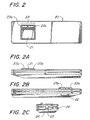
- FIG. 2 shows a top view of a preferred embodiment of a hand held basic remote control unit for use with the unit of FIG. 1;
- FIG. 2A shows a left side view of the basic remote control unit as shown in FIG. 2;
- FIG. 2B shows a right side view of the basic remote control unit as shown in FIG. 2;
- FIG. 2C shows an end view of the basic remote control unit shown in FIG. 2;
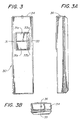
- FIG. 3 shows a top view of a preferred embodiment of a wireless enhanced transmitter unit;
- FIG. 3A shows a right side view of the enhanced transmitter unit as shown in FIG. 3;
- FIG. 3B shows an end view of the enhanced transmitter unit as shown in FIG. 3;
- FIG. 4 shows a top view of an alternative preferred wireless transmitter unit;
- FIG. 4A shows an end view of the wireless transmitter unit shown in FIG. 4;
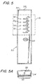
- FIG. 5 shows a top view of an alternative embodiment of a preferred wireless enhanced transmitter;
- FIG. 5A shows an end view of the alternative enhanced transmitter unit as shown in FIG. 5;
- FIG. 6 shows a functional flow diagram of the operation of the transmitter units;
- FIG. 7 shows top plan view of a preferred embodiment of an infrared lens;
- FIG. 8A illustrates the operation of the infrared lens shown in FIG. 7, when infrared light at an incident ray angle of 0° passes through lens;
- FIG. 8B illustrates the operation of the infrared lens shown in FIG. 7, when infrared light at an incident ray angle of 40° passes through lens;
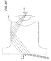
- FIG. 8C illustrates the operation of the infrared lens shown in FIG. 7, when infrared light at an incident ray angle of 80° passes through lens;
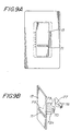
- FIG. 9A illustrates the installation of the infrared lens located in a moveable surface;
- FIG. 98 is an isometric illustration of the infrared lens located in a moveable surface and an infrared detector;
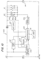
- FIG. 10 shows a block diagram of the circuitry of the receiver unit shown in FIG. 1;
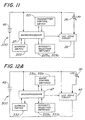
- FIG. 11 shows a block diagram of the circuitry of the basic remote control unit shown in FIG. 2;
- FIG. 12A shows a block diagram of the circuitry the enhanced remote control unit shown in FIG. 3;
- FIG. 12B shows a block diagram of the circuitry of the enhanced remote control unit shown in FIG. 4;
- FIG. 12C shows a block diagram of the circuitry of the enhanced remote control unit shown in FIG. 5;
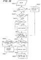
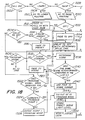
- FIGs. 13 - 20 show a functional flow diagram of the operation of the receiver unit; and
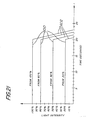
- FIG. 21 illustrates delay to off profiles for the power control device shown in FIG. 1.
- Referring now to the drawings, wherein like numerals indicate like elements, there is shown in FIG. 1 a power control and infrared
receiving control unit 10 embodying a power control device for controlling electric power delivered to at least one electrical device (not shown). Thecontrol unit 10 comprises a cover plate 11 and a plurality of control actuators comprising a user actuatable powerlevel selection actuator 12, a user actuatablecontrol switch actuator 13, hereinafter referred to as atoggle switch actuator 13, and an airgap switch actuator 18 which controls an air gap switch (not shown) for removing all electric power to thecontrol unit 10. Thecontrol unit 10 further comprises a power level indicator in the form of a plurality ofindividual LEDs 14 arranged in a line. - The
control unit 10 further comprises an infrared (IR) receivinglens 70 located in anopening 15 on thetoggle switch actuator 13. Thelens 70 captures IR control signals that are transmitted by any one of a number ofwireless transmitter units lens 70 will be described in more detail below. - In use, power control signals are transmitted to the
control unit 10 by a wireless hand held user actuatable basicremote control 20 or a wireless hand held user actuatable enhancedremote control - The
control unit 10 embodies a power control and infra-red receiver circuit 100 shown in Fig. 10, for controlling one or more electrical devices. Thecontrol unit 10 is designed to control the electric power delivered to at least one electrical device. - Preferably, the electrical device controlled by
control unit 10 is an electric lamp orlamps 114, as shown in Fig. 10. Thecontrol unit 10 controls the electric power delivered to, and hence the light intensity of, the electric lamp orlamps 114 in known manner by using a phase controlled triac circuit or otherwise. - However, it is to be understood that the electrical device could be a fan, a motor, a relay, etc. In addition, the type of
lamp 114 controlled is not limited to an incandescent lamp but could be a low voltage incandescent lamp, a fluorescent lamp, or other type of lamp. - The preferred embodiments described below are described in the context of the electrical device being a lamp or
lamps 114 and thecontrol unit 10 controlling the intensity of these lamps. - When the electrical device includes at least one lamp, the at least one lamp defines a lighting zone (hereinafter zone.) By incorporating
multiple control units 10, multiple zones can be created and controlled. The zones are used to create lighting scenes (hereinafter scenes) by controlling the power level, and therefore the intensity, of the lamps associated with one or more zones, thereby creating a plurality of scenes. Therefore, multiple scenes can be created with one or morepower control units 10, which can be controlled by the control unit or theremote transmitters - Hereinafter, the terms "actuation" or "actuated" mean either opening, closing, or maintaining closed for a particular period of time, a switch having one or more poles. In the preferred embodiment of the invention the switches are momentary contact switches and actuation is caused by the application of pressure to the switch actuator of sufficient force to either open or close a switch. However, other types of switches could be used.
- Referring to FIG. 1, the power
level selection actuator 12 is actuated by the user to set a desired level of light intensity of the one or more electric lamps controlled by thecontrol unit 10. Theselection actuator 12 further comprises an upper power level selector portion 12a and a lower powerlevel selector portion 12b, controlling respective powerlevel selector switches - The upper power level selector portion 12a, when actuated, causes an increase or "RAISE" in intensity of the lamps controlled by the
control unit 10. Conversely, the lower powerlevel selector portion 12b, when actuated withcontrol unit 10 in the on state, causes a decrease or "LOWER" in intensity of the lamps controlled by thecontrol unit 10. In addition, if the lower powerlevel selector portion 12b is actuated whencontrol unit 10 is in the off state, it can be used to set and store a delay to off time. The longer the lowerpower level selector 12b is actuated, the longer the delay time to be set and stored. - The actuation of user actuatable
control switch actuator 13 causes controlunit 10 to respond in a variety of ways, depending on the precise nature of the actuation ofcontrol switch actuator 13 which actuatescontrol switch 63, i.e., whether it is actuated for a transitory period of time or a longer than transitory period of time, or whether it is actuated for several transitory periods of time in quick succession, and also depending on the state of thecontrol unit 10 prior to the actuation of thecontrol switch actuator 13. - In the present, an actuation has a transitory duration if the duration of the actuation is less than 0.5 seconds. Two successive actuations of the actuator, in rapid succession (double tap), refers to two transitory actuations that are within 0.5 seconds of each other. Three successive actuations of an actuator, in rapid succession (triple tap), refers to three transitory actuations all within 1.0 second. Four successive actuations of an actuator, in rapid succession (quad tap), refers to four transitory actuations all within 1.5 seconds.
- Although these time periods are presently preferred for determining whether a double tap, triple tap, or quad tap actuations has occurred, any short period of time may be employed without departing from the invention. For example, a time period of 1.5 seconds could be used for determining whether a double tap, triple tap, or a quad tap has occurred so that in an alternative embodiment of the invention, if two successive actuations of transitory duration occurred in 1.5 seconds it would be considered a double tap. The period of time during which multiple successive actuations of transitory duration are looked for is considered to be a short duration of time.
- It is also possible to have an actuation of an actuator for more than 0.5 seconds, which is considered to be extended in nature and has an extended duration.
- The responses to the actuation of the
control switch actuator 13 are to increase the light intensity from zero to a preset level (FADE TO PRESET), increase the light intensity to maximum (FADE TO FULL), decrease the light intensity to zero (FADE TO OFF), decrease the light intensity to zero after a delay (DELAY TO OFF), store a preset light level in memory (LOCKED PRESET), and remove a preset light level from memory (DISCONTINUE LOCKED PRESET). These features are executed by means of circuitry associated with thecontrol unit 10 and depicted in a block diagram 100, shown in Fig. 10, described in detail in the flow charts illustrated in Figs. 13-20. - A FADE TO PRESET response is effected by a single actuation of transitory duration of the user actuatable
control switch actuator 13 when thecontrol unit 10 is in the off state, thereby causing the intensity of theelectric lamp 114 to increase at a first fade rate, from zero to a preset intensity level. This can be either a locked preset level or the level at which the lamp was illuminated when thecontrol unit 10 was last in an on state, as will be described in more detail below. - A FADE TO FULL response is effected by a double actuation, i.e., two actuations of transitory duration in rapid succession, of the user actuatable control switch actuator 13 (double tap), thereby causing the intensity of the
electric lamp 114 to increase, at a second fade rate, from an off state or any intensity level to a maximum intensity level. - A FADE TO OFF response is effected by a single actuation of transitory duration of the user actuatable
control switch actuator 13, thereby causing the intensity of theelectric lamp 114 associated with thecontrol unit 10 to decrease, at a third fade rate, from any intensity level to an off state. - A DELAY TO OFF response is effected by an "extended" actuation, i.e., a more than transitory actuation of the user actuatable
control switch actuator 13, thereby causing the intensity ofelectric lamp 114 to decrease at the third fade rate from any intensity level to an off state after a delay time. The duration of the delay time i.e., how long the delay time lasts from beginning to end, is dependent on the length of time thecontrol switch actuator 13 is actuated. In the preferred embodiment the delay time is linearly proportioned to the length of time thecontrol switch actuator 13 is actuated. - Actuations of less than 0.5 sec. are considered to be transitory or of short duration. Actuation of greater than 0.5 sec. cause an increase in the delay time of 10 seconds for each additional 0.5 second that control
switch actuator 13 is actuated. Hence, if thecontrol switch actuator 13 is held for two seconds, the delay time would be 30 seconds. - A variable fade to off could also be effected by an "extended" actuation of the
control switch actuator 13, causing the intensity ofelectric lamp 114 to decrease from any intensity to off with a variable fade rate. The variable fade rate is dependent on the duration of the actuation. Whether the unit has variable delay or variable fade to off on extended actuation of thecontrol switch actuator 13 is dependent on the programming of themicroprocessor 108 shown in Fig. 10. - A LOCKED PRESET response is effected by a triple actuation, i.e., three actuations of transitory duration in rapid succession of the user actuatable control switch actuator 13 (triple tap). The intensity of the
lamp 114 does not change but the intensity level is stored in a memory as a locked preset level, and subsequent chances to the intensity level of the lamp do not affect the locked preset level. - A DISCONTINUE LOCKED PRESET response is effected by a quadruple actuation, i.e., four actuations of transitory duration in rapid succession of the user actuatable control switch actuator 13 (quadruple tap). The intensity of the
lamp 114 does not change, but any intensity level stored in memory as a locked preset level is cleared. - If a locked preset level is stored in memory and the
control unit 10 is in an off state then a FADE TO PRESET response causes the intensity of theelectric lamp 114 to increase to the locked preset level. If no locked preset level is stored in memory and thecontrol unit 10 is in an off state, then a FADE TO PRESET response causes the intensity of theelectric lamp 114 to increase to the level at which thelamp 114 was illuminated when thecontrol unit 10 was last in an ON state. - Although the process of storing and clearing a locked preset level has been described with reference to multiple actuations of the
control switch actuator 13, this could also be accomplished by using two additional separate switches, one to store a locked preset level and one to clear the locked preset level, or by using one additional switch, successive actuations of which would alternately store and clear the locked preset power level. - If a delay time has been stored by actuating the lower power
level selector portion 12b when thecontrol unit 10 is in the off state as described above, then a FADE TO OFF response effected by a single actuation of transitory duration of the user actuatablecontrol switch actuator 13 when thecontrol unit 10 is in the on state causes the lights to remain at their present intensity for the duration of the stored delay time and then to decrease at a third fade rate to an off state. - FIG. 21 illustrates delay to off profiles for a 20 second delay to off of the
control unit 10. The profiles show how the light intensity levels of thelamp 114 change, starting from their current intensity level for four different beginning intensity levels. Thelamp 114 remains at the current intensity level for the delay time in thiscase 20 seconds before the intensity of the lamp decreases to zero. The delay to off time is variable and the preferred embodiment has a variable delay to off time range of 10 to 60 seconds in 10 second increments. Although these delay times are presently preferred, it should be understood that the delay to off times and the associated fade rate to off at the end of the delay time are not the only ones which may be used with the invention, and any desired delay, fade rate or combination thereof may be employed without departing from the invention. - The
control unit 10 will remain at thecurrent intensity level 600 for the duration of the delay time. At the end of the delay time, the intensity of thelamp 114 decreases to zero. Asuitable fade rate 602 for the decrease to zero may be 33 % per second. Preferably the delay times and fade rates are stored in the form of digital data in themicroprocessor 108, and may be called up from memory when required by the delay to off routine also stored in memory. - The delay to off profiles illustrated in FIG. 21 for a 20 second delay and similar profiles for the other possible delay to off times are used whether the
control unit 10 is performing a DELAY TO OFF in response to an extended actuation ofcontrol switch actuator 13 or it is delaying to off with a previously stored delay time in response to transitory actuation ofcontrol switch actuator 13. - The
control unit 10 and the cover plate 11 need not be limited to any specific form, and are preferably of a type adapted to be mounted to a conventional wall box commonly used in the installation of lighting control devices. - The
selection actuator 12 and thecontrol switch actuator 13 are not limited to any specific form, and may be of any suitable design which permits actuation by a user. Preferably, although not necessarily, theactuator 12 controls two separate momentarycontact push switches actuator 12 increases or raises the light intensity level, while actuation oflower portion 12b of theactuator 12 decreases or lowers the light intensity level. Preferably, but not necessarily, theactuator 13 controls a push-button momentarycontact type switch 53, but theswitch 53 may be of any other suitable type without departing from the scope of the present invention. - Similarly, although the effect of actuating the
control switch actuator 13 is described above with respect to specific actuation sequences ofcontrol switch 13 having specific effects, i.e., FADE TO FULL is effected by a double tap and LOCKED PRESET is effected by a triple tap, the linkage between the specific actuation sequence and the specific effect can be changed. - For example, in an alternative embodiment of the invention, FADE TO FULL could be effected by a triple tap.
- The
control unit 10 includes an intensity level indication in the form of a plurality ofintensity level indicators 14. The indicators are preferably, but need not be, light-emitting diodes (LEDs) or the like. -
Intensity level indicators 14 are arranged, in this embodiment, in a linear array representing a range of light intensities of the one or more lamps controlled by thecontrol unit 10. The range of light intensities is from a minimum (zero, or "off") to a maximum intensity level ("full on"). A visual indication of the light intensity of the controlled lights is displayed by the illumination of a singleintensity level indicator 14 preferably at 100% of its output when the lamps are on. - The
intensity level indicators 14 of the preferred embodiment illustrated in FIG. 1 show seven indicators aligned vertically in a linear array. By illuminating the uppermost indicator in the array, maximum light intensity level is indicated. By illuminating the center indicator, an indication is given that the light intensity level is at about the midpoint of the range, and by illuminating the lowermost indicator in the array, the minimum light intensity level is indicated. - Any convenient number of
intensity level indicators 14 can be used. By increasing the number of indicators in an array, the finer the gradation between intensity levels within the range can be achieved. In addition, when the lamp or lamps being controlled are off, all of theintensity level indicators 14 can be constantly illuminated at a low level of illumination preferably at 0.5 % of their maximum output for convenience of the user. The indicator representing the actual intensity level of the lamps when they return to the on state is illuminated at a slightly higher illumination level, preferably at 2% of its maximum output. These illumination characteristics enable theintensity level indicators 14 to be more readily perceived by the eye in a darkened environment, thereby assisting a user in locating the switch in a dark room, and constitute a "night light mode". An important feature of the present invention, in addition to controlling the lights in the room, is to provide sufficient contrast between the level indicators to enable a user to perceive the actual intensity level at a glance. - The
intensity level indicators 14 are also used to provide feedback to the user of thecontrol unit 10 regarding how thecontrol unit 10 is responding to the various actuations ofcontrol switch actuator 13 andselection switch actuator 12. - For example, when a FADE TO PRESET response is effected by a single actuation of transitory duration of
control switch actuator 13 when thecontrol unit 10 is in the off state, theintensity level indicators 14 change from the "night light mode" to illuminating the lowermost indicator followed by illuminating successively higher indicators in turn as the light intensity increases until the indicator which indicates the intensity of the preset light level is illuminated. - Further, when a FADE TO FULL response is effected by a double tap of the
control switch actuator 13, the intensity level indicators change from their original condition to illuminating successively higher indicators in turn until the uppermost indicator in the array is illuminated as the light intensity increases to full. - Further, when a FADE TO OFF response is effected by a single actuation of transitory duration of the
control switch actuator 13 when thecontrol unit 10 is in the on state, theintensity level indicators 14 change from their original condition to illuminating successively lower indicators in turn as the light intensity decreases to its lowest level. Finally, theintensity level indicators 14 indicate the "night light mode" when the light intensity decreases to zero. - Further, when a DELAY TO OFF response is effected by extended actuation of the
control switch actuator 13 when thecontrol unit 10 is in the on state, theintensity level indicators 14 first indicate the length of the delay time selected. After thecontrol switch actuator 13 has been held closed for 0.5 seconds, the lowermost indicator will cycle on and off to indicate that a 10 second delay has been selected, after a further 0.5 seconds the next highest indicator will cycle on and off to indicate that a 20 second delay has been selected, and so on, with successively higher indicators cycling on and off until thecontrol switch actuator 13 is released. - When the
control switch actuator 13 is released, the indicator indicating the present light intensity level cycles on and off during the delay time. At the end of the delay time, the indicator which indicates the present level is illuminated and then successively lower indicators are illuminated as the light decreases to its lowest level. Finally, theintensity level indicators 14 indicate the "night light mode" when the light intensity decreases to zero. - When a LOCKED PRESET response is effected by a triple actuation of the
control switch actuator 13, the intensity level indicator indicating the current light level of the lamp flashes twice at a frequency of 2Hz to indicate that the intensity level has been successfully stored. - When a DISCONTINUE LOCKED PRESET response is effected by a quadruple actuation of the
control switch actuator 13, the intensity level indicator indicating the current light level of the lamp flashes twice at a frequency of 2Hz to indicate that the intensity level has been cleared from memory. - When a RAISE response is effected by actuation of the upper portion 12a of the
selection actuator 12, theintensity level indicators 14 change from their original condition to illuminating successively higher indicators in turn as the actuation continues until either the actuation ends or the uppermost indicator in the array is illuminated when the light intensity reaches a maximum. - When a LOWER response is effected by actuation of the
lower portion 12b ofselection actuator 12 while thecontrol unit 10 is in the on state, theintensity level indicators 14 change from their original condition to illuminating successively lower indicators as the actuation continues until either the actuation ends or the lowermost indicator in the array is illuminated when the light intensity reaches a minimum. Thecontrol unit 10 does not turn off. - Finally, if the
lower portion 12b of theselection actuator 12 is actuated when thecontrol unit 10 is in the off state, theintensity level indicators 14 initially indicate the "night light mode". After thelower portion 12b has been actuated for 4.0 seconds, the lowermost indicator will cycle on and off to indicate that a 10 second delay has been selected, after a further 0.5 seconds the next highest indicator will cycle on and off to indicate that a 20 second delay has been selected, and so on, with successively higher indicators cycling on and off until thelower portion 12b is released. When thelower portion 12b is released, the indicator indicating the delay time selected flashes twice at a frequency of 2Hz to indicate that the delay time has been successfully stored and then theintensity level indicators 14 return to the "night light mode". - One embodiment of a basic infrared signal transmitting wireless
remote control unit 20 suitable for use with thecontrol unit 10 is shown in FIGS. 2, 2A, 2B and 2C. - The basic
wireless control unit 20 comprises a plurality of control actuators, comprising a user actuatable transmitter powerlevel selection actuator 23 and associated intensity selection switches 223 and a user actuatable transmittercontrol switch actuator 21 and associatedtransmitter control switch 221.Transmitter selection actuator 23 further comprises an increase powerlevel selector portion 23a and a decrease powerlevel selector portion 23b, controlling respectiveintensity selection switches - The basic
wireless control unit 20 further comprises an infra-red transmitting diode 26 which is located in anopening 25 in anend 24 of the basicwireless control unit 20 as best seen in FIG. 2C. Alternatively, basicwireless control unit 20 can further comprise anaddress switch 222 and anaddress switch actuator 22. which may be used in conjunction with a "send address" switch (not shown) as will be described in more detail below. Theswitches - Actuation of the increase power
level selector portion 23a, the lower powerlevel selector portion 23b, or the transmittercontrol switch actuator 21 of basic wirelessremote control unit 20 generally has the same effect as actuating the upper power level selector portion 12a, the lower powerlevel selector portion 12b or thecontrol switch actuator 13 respectively of thecontrol unit 10. - The actuation of the
actuators remote control unit 20 closes therespective switches microprocessor 27 and the information about which actuator has been operated is transmitted via infra-red signals from the infra-red transmitting diode 26 as will be described in more detail below in connection with the description of FIGS. 6 and 11. - The infrared signals are detected by an infra-
red receiver 104 and the signal information is passed to amicroprocessor 108 which interprets the signal information as will be described in more detail below in connection with the description of FIGS. 10 and 13 to 20. - In general, actuating an actuator on the basic wireless
remote control unit 20 has the same effect as operating the corresponding actuator on thecontrol unit 10. Thus, actuating the transmittercontrol switch actuator 21 for a transitory period of time will have the same effect as operating thecontrol switch actuator 13 on thecontrol unit 10 for a transitory period of time. (As described above, the exact effect may vary depending on the state of thecontrol unit 10 prior to the actuation). However, if desired, certain functions may be accessed only from thecontrol unit 10 and not from basic wirelessremote control unit 20 or vice versa. For example, the triple tap of transmittercontrol switch actuator 21 could have no effect on thecontrol unit 10, whereas the triple tap ofcontrol switch actuator 13 could have the effect described above. - One embodiment of an enhanced infra-red signal transmitting wireless
remote control unit 30 suitable for use with thecontrol unit 10 is shown in FIGS. 3, 3A and 3B. The enhancedwireless control unit 30 comprises a plurality of control actuators, comprising a user actuatable transmitter powerlevel selection actuator 33 and associated intensity selection switches 333, and a user actuatable transmitterscene control actuator 31 and associated switches 331.Transmitter selection actuator 33 further comprises an increase powerlevel selector portion 33a and a decrease powerlevel selector portion 33b, controlling respectiveintensity selection switches control actuator 31 further comprises a sceneselect actuator 31a and an off actuator 31b controlling respective scene control switches 331a, 331b. - The enhanced
wireless control unit 30 further comprises an infra-red transmitting diode 36 which is located in anopening 35 in anend 34 of the enhancedwireless control unit 30 as best seen in FIG. 2B. Alternatively the enhancedwireless control unit 30 can further comprise anaddress switch 332 and address switch actuator (not shown but the same as theaddress switch actuator 22 used with the basic wireless control unit 20). Theswitches - Actuation of the increase power
level selector portion 33a or the lower powerlevel selector portion 33b of the enhancedwireless control unit 30 generally has the same effect as actuating the upper power level selector portion 12a or the lower powerlevel selector portion 12b of thecontrol unit 10, respectively. - Actuation of the scene
select actuator 31a for a transitory period of time causes the light intensity of theelectric lamp 114 to change at the first fade rate from its present intensity level (which can be off) to a first preprogrammed preset intensity level. - Actuation of the scene
select actuator 31a for two transitory periods of time in rapid succession causes the light intensity of theelectric lamp 114 to change at the first fade rate from its present intensity level (which can be off) to a second preprogrammed preset intensity level. - The method for preprogramming the preset intensity levels will be described in detail below.
- Actuation of the off actuator 31b generally has the same effect as actuating the
control switch actuator 13 of thecontrol unit 10 when thecontrol unit 10 is in an on state and is delivering a non-zero power level to the lamp under control; and has no effect when thecontrol unit 10 is in an off state and delivering zero power to the lamp. Hence, by actuating the off actuator 31b, it is possible to effect a fade to off response or a delay to off response from thecontrol unit 10. - The actuation of the
actuators remote control unit 30 closes therespective switches microprocessor 47, and the information about which actuator has been operated is transmitted via infra-red signals from the infra-red transmitting diode 36 as will be described in more detail below in connection with the description of FIGS. 6 AND 12A. - The infrared signals are detected by an infra-
red receiver 104 and the signal information is passed to amicroprocessor 108 which interprets the signal information as will be described in more detail below in connection with the description of FIGS. 10 AND 13-20. - A second embodiment of an enhanced infra-red transmitting wireless
remote control unit 40 suitable for use with thecontrol unit 10 is shown in FIGS. 4 AND 4A. The enhancedwireless control unit 40 comprises a plurality of control actuators, comprising a user actuatable transmitter powerlevel selection actuator 43 and associated intensity selection switches 443, and user actuatable transmitterscene control actuators 41 and associated switches 441. Thetransmitter selection actuator 43 is a paddle actuator which is moved upwards to actuate increase intensity selection switch 443a and is moved downwards to actuate decrease intensity selection switch 443b. Thescene control actuators 41 comprise sceneselect actuators 41a, 41b, 41c, 41d and an off actuator 41e controlling respectivescene control switches 441a, 441b, 441c, 441d, 441e. - The enhanced
wireless control unit 40 further comprises an infra-red transmitting diode 46 which is located in anopening 45 in anend 44 of the enhancedwireless control unit 40 as best seen in FIG. 4A. Alternatively enhancedwireless control unit 40 can further comprise an address switch 442 and an address switch actuator (not shown but the same as theaddress switch actuator 22 used with the basic wireless control unit 20). Theswitches 441a, 441b, 441c, 441d, 441e, 442, 443a, 443b are shown in FIG. 12B. - Actuation of increase intensity switch 443a by moving the transmitter selection actuator upward generally has the same effect as actuating the upper power level selector portion 12a of the
control unit 10. Similarly, actuation of decrease intensity selection switch 443b by moving the transmitter selection actuator downward generally has the same effect as actuating the lower powerlevel selector portion 12b of thecontrol unit 10. - Actuation of each of the scene
select actuators 41a, 41b, 41c, 41d for a transitory period of time causes the light intensity of theelectric lamp 114 to change at the first fade rate from its present intensity level (which can be off) to first, second, third, and fourth preprogrammed preset intensity levels, respectively. - Actuation of each of the scene
select actuators 41a, 41b, 41c, 41d for two transitory periods of time in rapid succession causes the light intensity of theelectric lamp 114 to change at the first fade rate from its present intensity level (which can be off) to fifth, sixth, seventh, and eighth preprogrammed preset intensity levels, respectively. - The method for preprogramming the preset intensity levels will be described in detail below.
- Actuation of the off actuator 41e generally has the same effect as actuating the
control switch actuator 13 of thecontrol unit 10 when thecontrol unit 10 is in an on state and is delivering a non-zero power level to the lamp under control; and has no effect whencontrol unit 10 is in an off state and delivering zero power to the lamp. Hence, by actuating the off actuator 41e, it is possible to effect a fade to off response or a delay to off response from thecontrol unit 10. - The actuation of the
actuators remote control unit 30 closes therespective switches 443a, 443b, 441a, 441b, 441c, 441d, 441e which they actuate. The switch closure is detected by amicroprocessor 47, and the information about which actuator has been operated is transmitted via infra-red signals from the infra-red transmitting diode 46 as will be described in more detail below in connection with the description of FIGS. 6 AND 12B. - The infra-red signals are detected by an infra-
red receiver 104 and the signal information is passed to amicroprocessor 108 which interprets the signal information as will be described in more detail below in connection with the description of FIGS. 10 AND 13-20. - A third embodiment of an enhanced infra-red transmitting wireless
remote control unit 50 suitable for use with thecontrol unit 10 is shown in FIGS. 5 AND 5A. - The enhanced
wireless control unit 50 comprises a plurality.of control actuators comprising a user actuatable transmitter powerlevel selection actuator 53 and associated intensity selection switches 553, and user actuatable transmitterscene control actuators 51 and associated switches 551. Thetransmitter selection actuator 53 is a paddle actuator which is moved upwards to actuate increaseintensity selection switch 553a and is moved downwards to actuate decreaseintensity selection switch 553b. Thescene control actuators 51 comprise scene select actuators 51a, 51b, 51c. 51d and an off actuator 51e controlling respective scene control switches 551a, 551b, 551c, 551d, 551e. Thescene control actuator 51 further comprise special function select actuators 51f, 51g, 51h, 51i controlling respective specialfunction control switches 551f, 551g, 551h, 551i. - The enhanced
wireless control unit 50 further comprises an infra-red transmitting diode 56 which is located in anopening 55 in anend 54 of the enhancedwireless control unit 50 as best seen in FIG. 5A. Alternatively enhancedwireless control unit 50 can further comprise anaddress switch 552 and an address switch actuator (not shown but the same as theaddress switch actuator 22 used with the basic wireless control unit 20). Theswitches - Actuation of
increase intensity switch 553a by moving the transmitter selection actuator upward generally has the same effect as actuating the upper power level selector portion 12a of thecontrol unit 10. Similarly, actuation of decreaseintensity selection switch 553b by moving the transmitter selection actuator downward generally has the same effect as actuating the lower powerlevel selector portion 12b of thecontrol unit 10. - Actuation of each of the scene select actuators 51a, 51b, 51c, 51d for a transitory period of time causes the light intensity of the
electric lamp 114 to change at the first fade rate from its present intensity level (which can be off) to first, second, third, and, fourth preprogrammed preset intensity levels, respectively. - Actuation of each of the scene select actuators 51a, 51b, 51c, 51d for two transitory periods of time in rapid succession causes the light intensity of the
electric lamp 114 to change at the first fade rate from its present intensity level (which can be off) to fifth, sixth, seventh, and eighth preprogrammed preset intensity levels, respectively. - The
third embodiment 50 of the enhanced transmitter differs from thesecond embodiment 40 of the enhanced transmitter in that it further comprises special function actuators 51f, 51g, 51h, 51i controlling respectivespecial function switches 551f, 551g, 551h, 551i. These special function actuators can be used to select ninth, tenth, eleventh, and twelfth preprogrammed preset intensity levels, respectively, or to select special functions. Alternatively, some special function actuators can be used to select preprogrammed preset intensity levels and some can be used to select special functions. - The method for preprogramming the preset intensity levels and the nature of the special functions will be described in detail below.
- Actuation of the off actuator 51e generally has the same effect as actuating the
control switch actuator 13 of thecontrol unit 10 when thecontrol unit 10 is in an on state and is delivering a non-zero- power level to the lamp under control; and has no effect whencontrol unit 10 is in an off state and delivering zero power to the lamp. Hence, by actuating the off actuator 51e, it is possible to effect a fade to off response or a delay to off response from thecontrol unit 10. - The actuation of the
actuators 53, 51a, 51b, 51c, 51d, 51e, 51f, 51g, 51h, 51i on the enhanced wirelessremote control unit 30 closes therespective switches microprocessor 47, and the information about which actuator has been operated is transmitted via infra-red signals from the infra-red transmitting diode 56 as will be described in more detail below in connection with the description of FIGS. 6 AND 12C. - The infra-red signals are detected by an infra-
red receiver 104 and the signal information is passed to amicroprocessor 108 which interprets the signal information as will be described in more detail below in connection with the description of FIGS. 10 AND 13-20. - The method for preprogramming the preset intensity levels accessed from the enhanced
wireless control units - Programming mode for the
control unit 10 is entered by actuating a combination of actuators on the enhanced remote controls and keeping the switches controlled by the actuators closed for a certain length of time, preferably 3 seconds, while transmitting infra-red signals from the transmitter to controlunit 10 at which time thecontrol unit 10 enters programming mode. - For the embodiment of the enhanced
remote control 30 illustrated in FIGS. 3, 3A AND 3B, programming mode is entered by actuating the sceneselect actuator 31a and the off actuator 31b at the same time. For theembodiment 40 illustrated in FIGS. 4 AND 4A, programming mode is entered by actuating the sceneselect actuator 41a and the off actuator 41e at the same time. For theembodiment 50 illustrated in FIGS. 5 AND 5A, programming mode is entered by actuating the scene select actuator 51a and the off actuator 51e at the same time. - The
control unit 10 enters the programming mode ready to program the first preset intensity level. The uppermost indicator 14 (which is indicating that the first preset intensity level is being programmed) flashes on and off with a duty cycle of approximately 10 % and theindicator 14 corresponding to the light intensity level currently programmed as the first preset intensity level flashes on and off with a 90 % duty cycle. Duty cycle here refers to the relative amount of time that oneindicator 14 is on as opposed to anotherindicator 14 being on. Only oneindicator 14 is ever illuminated at one time due to constraints within the power supply powering theindicator 14. - The light intensity level to be stored is adjusted by actuating the increase power
level selector portion 33a or lower powerlevel selector portion 33b or the off actuator 31b for the embodiment of the enhancedremote control 30 illustrated in FIGS. 3, 3A AND 3B, by actuating the powerlevel selection actuator 43 either up or down to actuate increase intensity selection switch 443a or decrease intensity selection switch 443b or the off actuator 41e for the embodiment of the enhanced remote 40 illustrated in FIGS. 4 AND 4A, by actuating the powerlevel selection actuator 53 either up or down to actuate increaseintensity selection switch 553a or decreaseintensity selection switch 553b or the off actuator 51e for the embodiment of the enhanced remote 50 illustrated in FIGS. 5 AND 5A. For all embodiments of the enhancedremote control level selector portion 12b of thecontrol unit 10. - As the intensity is adjusted, the light intensity of
electric lamp 114 changes and theindicator 14 which is illuminated with a 90 % duty cycle also changes to indicate the new current light level. - Once the desired intensity level to be programmed as the first preset intensity level (which may be off), has been reached either another preset intensity level to be programmed is selected or programming mode is exited. In the case of the enhanced
remote control 30 illustrated in FIGS. 3, 3A AND 3B, only a first preset intensity level can be programmed, so the only option at this point is to exit programming mode. - If it is desired to program another preset intensity level, then this is selected by actuating a scene select actuator 41b, 41c, 41d for a transitory period of time for the embodiment of the enhanced remote control illustrated in FIGS. 4 AND 4A or a scene select actuator 51b, 51c, 51d for a transitory period of time for the embodiment of the enhanced remote control illustrated in FIGS. 5 AND 5A.
- These scene select actuators select second, third, and fourth preset intensity levels to be programmed respectively. The second
highest indicator 14 flashes on and off with a 10% duty cycle when the second preset intensity level has been selected, the thirdhighest indicator 14 flashes on and off with a 10% duty cycle when the third preset intensity level has been selected and themiddle indicator 14 flashes on and off with a 10% duty cycle when the fourth preset intensity level has been selected. - Actuating a scene
select actuator 41a, 41b, 41c, 41d, 51a, 51b, 51c, 51d for two transitory periods of time enables the selection of the fifth, sixth, seventh, and eighth preset intensity levels to be programmed, respectively. - The highest, second highest, third highest, and
middle indicator 14 will flash on and off with a duty cycle other than 10 % to indicate that either the fifth, sixth, seventh, or eighth preset intensity level to be programmed has been selected. - If the embodiment of the enhanced
transmitter 50 illustrated in FIGS. 5 AND 5A is being used to select ninth, tenth, eleventh, and twelfth preset intensity levels from the special function actuators 51f, 51g, 51h, 51i, these can be selected for programming by actuating a special function actuator 51f, 51g, 51h, 51i. - The highest, second highest, third highest, and
middle indicator 14 will flash on and off with a second duty cycle other than 10% to indicate that either the ninth, tenth, eleventh, or twelfth preset intensity level to be programmed has been selected. - The light intensity to be stored is adjusted in the same manner as described above for programming the first preset intensity level.
- Once all the desired preset intensity levels have been programmed, programming mode is exited by actuating the same combination of actuators which were used to enter programming mode again for a period of time, preferably 3 seconds. while transmitting infra-red signals from the transmitter to the
control unit 10. At the end of the period, the control unit exits programming mode. Alternatively, programming mode can be exited by actuatingactuator 13 oncontrol unit 10 for a transitory period of time. - The operation of the special function actuators 51f, 51g, 51h, 51i on the enhanced
transmitter 50 is dependant on the particular special functions programmed into thecontrol unit 10 which receives the infrared signals. - One alternative is to use the special function selection actuator to select additional programmed intensity levels as described above. A first special function which can be selected by a first special function actuator is "FADE TO OFF WITH DETERMINED FADE TIME". This function is similar to "DELAY TO OFF" except that, whereas in the case of the "DELAY TO OFF" the light intensity of
lamp 114 remains at its current intensity during the delay time and then decreases to zero over a relatively short period of time, in the case of "FADE TO OFF WITH DETERMINED FADE TIME" the light intensity level oflamp 114 immediately begins to decrease in value once the actuator is released and then continues to decrease in value until it reaches zero at the end of the "DETERMINED FADE TIME" . - The "DETERMINED FADE TIME" is determined by the length of time that the first special function actuator has been actuated. The longer the actuator is actuated, the longer the fade time.
- After the first special function actuator has been actuated the
indicator 14 will flash the lowest LED to indicate a fade time of 10 sec has been selected. For each additional 0.5 sec that the first special function actuator is actuated the fade time increases by 10 sec to a maximum of 60 sec. Successivelyhigher indicators 14 are flashed to indicate the increasing fade time selected. When the first special function actuator is released, the decrease in light intensity oflamp 114 begins to occur and theindicator 14 indicating the current light intensity is flashed. Successivelylower indicators 14 are flashed as the light intensity oflamp 14 is decreased until theindicator 14 indicates the "Night light mode" whenlamp 114 is at zero power. - A second special function which can be selected by a second special function actuator is "RETURN TO PREVIOUS LIGHT LEVEL". This function causes the light intensity of
lamp 114 to return to the last preset level it had prior to the last actuation of a scene select actuator, a control switch actuator, or a power level selector actuator. - In this way it is possible for the user of the
control unit 10 to return to the last selected preset level which could be a preprogrammed preset intensity level, a locked preset intensity level or an unlocked preset intensity level. The intensity level oflamp 114 will gradually increase or decrease from the current intensity level to the intensity level being returned to, and theindicator 14 will change from illuminating the LED corresponding to the current intensity level to illuminating successively higher or lower LEDs until theindicator 14 indicating the intensity level of the last selected preset level is illuminated. - Other special functions can optionally be programmed into the
control unit 10 and selected by actuating different special function actuators. - The operation of the optional
address switch actuator 22 andaddress switch wireless control unit 20, and the three embodiments of the enhancedwireless control unit - The first use of the optional
address switch actuator 22 and the send address switch is to labelcontrol unit 10 with a particular address.Address switch actuator 22 controls an address switch, 222, 332, 442, 552 which is typically a multiposition switch, for selecting between different address A, B, C, D, etc. If it is desired to label aparticular control unit 10 with address B, then the address switch actuator would be adjusted to select B, and then the send address switch would be actuated. The send address switch is not shown, but could have any desired form. Preferably, the send address switch is actuated by a small and inconspicuous actuator since it is used infrequently. Alternatively, the actuator for the send address switch could be hidden under normal use for, for example under a battery compartment cover for thewireless control unit - Alternatively in the case of the three embodiments of enhanced
wireless control unit level selector portion 33a, or moving thetransmitter selection actuator - After the send address switch has been actuated or the appropriate combination of actuators has been actuated, an infrared signal is sent from the
wireless control unit control unit 10 which receives the signal to label itself with address B. Theintensity level indicator 14 indicating the current intensity level of the lamp flashes three times at a frequency of 2Hz to indicate that the address has been successfully received and stored in a memory. - Alternatively, the
intensity level indicator 14 indicating the current intensity level of thelamp 114 flashes at a frequency of 2Hz until thecontrol switch actuator 13 is actuated for a transitory period of time to store the address in memory. Ifactuator 13 has not been actuated within 2 minutes of thecontrol unit 10 receiving the infra-red signal, then no address is stored and thecontrol unit 10 returns to the state which it was in prior to receiving the infra-red signal. - In this way, it is possible to label a plurality of
control units 10 with the same or different addresses. - Once all the
control units 10 desired to be controlled by thewireless control unit wireless control unit control units 10 which have been labelled with a particular address in the following manner. - The
address switch actuator 22 is adjusted to the position which selects the address of thecontrol units 10 which were desired to be controlled, for example A. After that has been done, any signals sent fromwireless control unit select actuation transmitter selection actuator - Only those
control units 10 which have previously been labelled with address A will respond to the infra-red signals which contain address information A.Other control units 10 will not respond. In this way, by labelling a plurality ofcontrol units 10 with different addresses, it is possible to control eachcontrol unit 10 individually, even if all units receive the infra-red signals. - It is also possible for the
address switch actuator 22 to select an ALL address. This cannot be used to labelcontrol units 10. However, once thecontrol units 10 have been labelled with individual addresses A, B, C, etc., then selecting the ALL address with theaddress switch actuator 22 causes the infra-red signals transmitted fromwireless control unit control units 10 which receive the infra-red signals with the ALL address will respond regardless of the individual addresses with which they have been labelled. - Turning to FIG. 10, the circuitry of the
power control unit 10 is depicted in the control unit block diagram 100. The circuitry, with the exception of wireless remote control operation, is well known to one skilled in the art, and is fully described in U.S. Patent 5,248,919. Therefore, a detailed description of the circuit is not reproduced herein, and only the new features of the system are described below. - The preferred embodiment of the present invention provides the features of wireless remote control operation, as described below, in combination with the light control disclosed in U.S. Patent 5,248,919. In the preferred embodiment of the present invention, the circuitry of the
power control unit 10 is commanded by infra-red control signals transmitted by wirelessremote control units power control unit 10. Aninfrared receiver 104 responds to the infra-red control signals and converts them to electrical control signal inputs to amicroprocessor 108 in a similar manner to which thesignal detector 102 responds to control signals fromswitches 110 located inpower control unit 10 as well as control signals from switches 111 within wired remote lighting control units and provides control signal inputs tomicroprocessor 108 of the present invention are similar to the control signals, signal detector 32, andmicroprocessor 28 disclosed in U.S. Patent 5,248,919. However, the program running is different and provides additional functions and features not disclosed in U.S. Patent 5,248,919. - In the present invention, control signal inputs are generated by switch actuators on the
power control unit 10, by switch actuators on a user actuatable wirelessremote control unit microprocessor 108 for processing. Themicroprocessor 108 then sends the appropriate signals on to the remaining portion of the control circuitry which in turn control the intensity levels and state of thelamp 114 associated with thecontrol unit 10. - A block diagram of the
control circuit 200 of basicremote control unit 20 is depicted in FIG. 11. Theintensity selection actuator 23 actuatesintensity selection switches control switch actuator 21 actuatestransmitter control switch 221 to provide inputs to amicroprocessor 27. Themicropocessor 27 provides encoded control signals to anLED drive circuit 28. which drives anLED 26 to produce and transmit infrared signals encoded by themicroprocessor 27. TheLED 26 is located in theIR transmitter opening 25, embodied in theend wall 24 of the user actuatable basicremote control unit 20. - The
address switch actuator 22 actuates theaddress switch 222 to provide inputs to themicroprocessor 27. A "SEND ADDRESS" switch not shown in FIG. 11 would also provide input to themicroprocessor 27 as described above. -
Battery 49 provides power to basicremote control unit 20. - The
microprocessor 27 has a preprogrammed software routine which controls its operation. The operation of the routines in themicroprocessor 27 is illustrated in flow chart form in FIG. 6. There is one major flow path, or routine, which the program in themicroprocessor 27 follows. This path is selected whenever the "ACTUATOR OR ACTUATORS OPERATED?"decision node 2000 is "yes". This occurs whenever thecontrol switch actuator 21 or the powerlevel selection actuator 23 is actuated. Following the "ACTUATOR OR ACTUATORS OPERATED?" decision node is the "DETERMINE WHICH ACTUATOR OR ACTUATORS WERE OPERATED?"node 2004 where a determination is made as to which actuator or actuators were operated. Following the "DETERMINE WHICH ACTUATOR OR ACTUATORS WERE OPERATED"node 2004 is the "DETERMINE ADDRESS"node 2006, where themicroprocessor 27 determines the setting of theaddress switch 222. Themicroprocessor 27 then proceeds to "LOOK UP A NUMBER WHICH CORRESPONDS TO THE ACTUATOR OR ACTUATORS OPERATED AND THE ADDRESS SELECTED" 2008. The microprocessor then "ENCODES NUMBER" 2010 and then "TRANSMITS CODE" 2012. - If the
control switch actuator 21 or powerlevel selection actuator 23 is not actuated by a user, theremote control unit 20 enters a "SLEEP MODE" 2002 and no change is made to the state of thecontrol unit 10. - A block diagram of each of the
control circuits remote control units transmitter control switch 221 in the block diagram 200, thescene control switches 441a, 441b, 441c, 441d, 441e in the block diagram 400 replacing thetransmitter control switch 221 in the block diagram 200, and the scene control switches 551a, 551b, 551c, 551d, 551e, andspecial function switches 551f, 551g, 551h, 551i in the block diagram 500 replacing thetransmitter control switch 221 in the block diagram 200. - The scene control switches provide inputs to the
microprocessor 47. Themicroprocessor 47 provides encoded control signals to anLED drive circuit 48 which drives anLED microprocessor 47. These signals are transmitted through theIR opening end wall remote control units - An
address switch actuator 22 of the enhancedremote control units address switch microprocessor 47. A send address switch, not shown in Figures 12A, 12B, and 12C would also provide input to themicroprocessor 47. - The enhanced
remote control units decision node 2000 in FIG. 6 is "yes" whenever a scene control switch or a power level intensity selector switch is actuated. - Turning to FIGs 13 through 20, the
microprocessor 108 of thecontrol unit 10 has preprogrammed software routines which control its operation. The operation of the routines in themicroprocessor 108 is illustrated in flow chart form in FIG 13 through 20. Referring to FIG 13, there are four major flow paths, or routines, which themicroprocessor 108 can follow. These paths are selected depending on the source of the input control signals. The first three paths,RAISE 1030,LOWER 1024, andTOGGLE 1036 are selected when thepower selection actuator 12 or thecontrol switch actuator 13 are actuated, as discussed above. - The function of the preprogrammed software routines for the operation by wireless remote control will also be discussed in detail, this is the fourth path, "IR SIGNAL" 1012.
- Referring to FIG 13, the program begins at "MAIN" 1000 as shown. The first decision node encountered is the "IN IR PROGRAM MODE?" 1002. The program determines if the
control unit 10 is in program mode so that preprogrammed light intensities can be stored. If the output from "IN IR PROGRAM MODE" decision node 1002 is "yes", the next decision node is "HAS AN ACTUATOR OR IR SIGNAL BEEN RECEIVED WITHIN THE LAST TWO MINUTES?" 1004. Decision node 1004 performs a time out function to determine if the user is confused while in programming mode. If the user does not touch the actuators on the control unit within two minutes, the unit will automatically exit from program mode and stop flashingindicators 14 that are being flashed. If the output from decision node 1004 is "no", thecontrol unit 10 is commanded to "EXIT PROGRAM MODE" 1026 and "STOP FLASHING LEDS" 1028 and the program returns to "MAIN" 1000. If the output from decision node 1004 is "yes", the program proceeds to the "ACTUATOR OPERATED?"decision node 1006. A check is made as to whether any actuators have been actuated on thecontrol unit 10 i.e., the powerlevel selection actuator 12 or thecontrol switch actuator 13. - If the output of the "ACTUATOR OPERATED?"
decision node 1006 is "yes", the program proceeds to "IN IR PROGRAM MODE?" decision node 1018, where a check is made as to whether thecontrol unit 10 is in program mode again. If the output of the "IN IR PROGRAM MODE?" decision node 1018 is "yes", the program proceeds to "GO TO IR PROGRAM MODE ROUTINE" 1020. This is shown in greater detail in the IR Program Mode routine 1100, shown in FIG 14. - If the output from decision node 1018 is "no", the program proceeds to the "RAISE?"
decision node 1030 where a check is made as to whether the upper power level selector portion 12a has been actuated. If the output from the "RAISE" decision node is "yes", the program proceeds to the "GO TO RAISE ROUTINE" 1032. The "RAISE" routine 1400 is shown in greater detail in FIG 16. - If the output of the "RAISE"
decision node 1030 is "no", the program proceeds to the "LOWER?"decision node 1022 where a check is made as to whether the lower powerlevel selector portion 12b has been actuated. If the output from the "LOWER"decision node 1022 is "yes", the program proceeds to the "GO TO LOWER ROUTINE" 1024. The "LOWER" routine 1200 is shown in greater detail in FIG 15. - If the output from the "LOWER?"
decision node 1022 is "no", the program proceeds to the "TOGGLE?" decision node 1034 where a check is made as to whether thecontrol switch actuator 13 has been actuated. If the output of the "TOGGLE" decision node 1034 is "yes", the program proceeds to the "GO TO TOGGLE ROUTINE" 1036. The "TOGGLE" routine 1300 is shown in greater detail in FIG 17. If the output of the "TOGGLE" node 1034 is "no", the program then returns to "MAIN" 1000. - If the output of the "ACTUATOR OPERATED?"
decision node 1006 is "no" , the program proceeds to the "HAS AN ACTUATOR BEEN OPERATED IN THE LAST TWO MINUTES?"decision node 1008. Thedecision node 1008 runs another time out check to determine if any control actuators have been operated in the last two minutes. If the output from thedecision node 1008 is "yes", the program proceeds to the "IR SIGNAL?"decision node 1010 where a determination is made as to whether an IR signal has been received. If the output of the "IR SIGNAL?"decision node 1010 is "yes", the program proceeds to "GO TO IR SIGNAL ROUTINE" 1012. The "IR SIGNAL ROUTINE" 1500 is shown in greater detail in FIGs 18, 19, 20. If the output of the "IR SIGNAL?"decision node 1010 is "no", the program proceeds to "UPDATE LEDS" 1014 where the status of theintensity indicators 14 are updated, and the program returns to "MAIN" 1000. Thecontrol unit 10 is constantly updating the LED display even if no actuators are actuated or if no IR signals are received. If the "HAS AN ACTUATOR BEEN OPERATED IN THE LAST TWO MINUTES?"decision node 1008 is "no", the program proceeds to "RESET LEARN ADDRESS MODE" 1016 and then proceeds on to the "IR SIGNAL?"decision node 1010. - After the program proceeds to the "LEARN ADDRESS MODE?" 1590, which will be described in more detail below, and "SAVE NEW ADDRESS" 1580, the program is looking for a confirmation signal. If the control unit does not receive the confirmation signal within two minutes the "LEARN ADDRESS MODE" is reset and the new address received is erased.
- Turning now to FIG 14, the first decision node encountered in "IR PROGRAM MODE" is "TOGGLE?" 1102. IR program mode is where preset light intensity levels can be stored in the
control unit 10 by actuating actuators on thecontrol unit 10 or on anenhanced wireless transmitter control switch actuator 13 has been actuated. If the output of the node is "yes", thecontrol unit 10 is commanded to "STOP FLASHING LEDS" 1104 where any flashingindicators 14 are extinguished. The program continues to "EXIT PROGRAM MODE" 1106, and "UPDATE LEDS" 1108 where theindicators 14 are updated to the correct status, and the program proceeds to "RETURN TO TOP OF MAIN" 1110. This is one way of exiling program mode. Another way will be described in detail below. - If the output of "TOGGLE?"
decision node 1102 is "no", the next decision node is "RAISE?" 1112 where a determination is made as to whether the upper power level selector portion 12a has been actuated. If the output of the node is "yes", the program moves on to the "AT HIGH END?" decision node 1114. If the output of the "AT HIGH END?" decision node 1114 is "yes", the light intensity of thelamp 114 can not be increased any more, so no changes are made and the program proceeds "RETURN TO TOP OF MAIN" 1110. If the output of the "AT HIGH END?" decision node 1114 is "no", thecontrol unit 10, is commanded to "INCREASE LIGHT LEVEL BY ONE STEP" 1116 where the output power of thecontrol unit 10 is increased. The program continues to "DETERMINE SCENE" 1118 where the program checks which scene is being programmed. - The unit then encounters the "HAS THE SAME ACTUATOR BEEN OPERATED IN THE LAST 0.5 SEC?"
decision node 1120. This decision node function is included so that by actuating actuators multiple times, additional functions can be accessed. If the output of thedecision node 1120 is "no", the unit is commanded to "SAVE LIGHT LEVEL AS SCENE PRESET" 1130, where a new intensity level is stored for the scene select actuator being programmed. - The program proceeds to "RETURN TO TOP OF MAIN" 1100. If the output of the "HAS THE SAME ACTUATOR BEEN OPERATED IN THE LAST 0.5 SEC?"
decision node 1120 is "yes", i.e., multiple actuations of an actuator have occurred within a certain time period, the unit is commanded to "ADD FOUR TO THE SCENE NUMBER" 1122, and "SAVE LIGHT LEVEL AS SCENE PRESET" 1130 and the program proceeds to "RETURN TO TOP OF MAIN" 1000. - If the output of the "TOGGLE?"
decision node 1102 is "no" and the output of "RAISE?" decision node 1112 is "no", the program moves to the next major routine and enters the "LOWER?"decision node 1124. A determination is made as to whether the lower powerlevel selector portion 12b has been actuated. If the output fromdecision node 1124 is "no". no changes are made and the program proceeds to "RETURN TO TOP OF MAIN" 1110. If the output ofdecision node 1124 is "yes", the program proceeds to the "AT LOW END OR OFF?"decision node 1126. A determination is made as to whether thelamp 1 14 is at minimum light intensity or off. If the output fromdecision node 1120 is "yes", the light intensity can not be decreased further, no changes are made and the program proceeds to "RETURN TO TOP OF MAIN" 1110. If the output fromdecision node 1126 is "no", thecontrol unit 10 is commanded to "DECREASE LIGHT LEVEL BY ONE STEP" 1128 where the output power of thecontrol unit 10 is decreased and "DETERMINE SCENE" 1118 where once again the unit checks which scene is being programmed. - The program proceeds on to "HAS THE SAME ACTUATOR BEEN OPERATED IN THE LAST 0.5 SEC?"
decision node 1120. If the output fromdecision node 1120 is "no", the unit is commanded to "SAVE LIGHT LEVEL AS SCENE PRESET" 1130, where the new intensity is stored for the scene select actuator being programmed. The program proceeds to "RETURN TO TOP OF MAIN" 1110. If the output of "HAS THE SAME ACTUATOR BEEN OPERATED IN THE LAST 0.5 SEC?"decision node 1120 is "yes", the unit is commanded to "ADD FOUR TO THE SCENE NUMBER" 1122, and "SAVE LIGHT LEVEL AS SCENE PRESET" 1130, and then program proceeds to "RETURN TO TOP OF MAIN" 1110. - Turning now to FIG 15 and the "LOWER" routine 1200, the first decision node encountered is "UNIT ON?" 1202 where a determination is made as to whether the
control unit 10 is in the "ON STATE". If the output from the "UNIT ON?" decision node 1202 is "yes", the program proceeds to the "AT LOW END?" decision node 1204 where a determination is made as to whether thelamp 114 is at a minimum light intensity. If the output from the decision node 1204 is "yes", the light intensity can not be decreased any more, no changes are made and the program proceeds to "RETURN TO TOP OF MAIN" 1206. If the output of the "AT LOW END?" decision node 1204 is "no", the program proceeds to the "FADING"decision node 1222. A determination is made as to whether thecontrol unit 10 is in a steady state, or is fading between two different output light intensity levels. If the output fromdecision node 1222 is "yes", thecontrol unit 10 is fading between two different light intensity levels hence thecontrol unit 10 is commanded to "STOP FADING" 1224 and to "DECREASE LIGHT LEVEL BY ONE STEP" 1212, and the output power ofcontrol unit 10 is decreased. The next decision node encountered is the "WAS IT AN IR COMMAND?" 1214. - If the output of the "FADING"
decision node 1222 is "no", then the power output fromcontrol unit 10 is in a steady state, and thecontrol unit 10 is commanded to "DECREASE LIGHT LEVEL BY ONE STEP" 1212 and the output power ofcontrol unit 10 is decreased. The program then proceeds to the "WAS IT AN IR COMMAND?" decision node 1214 where a determination is made as to whether an infra-red signal has been received which caused the program to enter the "LOWER" routine 1200. - If the output from the "WAS IT AN IR COMMAND?" decision node 1214" is "yes", the program proceeds to "UPDATE LEDS" 1216, and then "RETURN TO TOP OF MAIN" 1206. No change is made to any stored preset levels because LOWER commands from the wireless transmitter only affect the current light intensity unless the
control unit 10 is in program mode. Further as described below any light intensity levels adjusted by using the user actuatable intensity selection actuator on thecontrol unit 10 are temporary if the locked preset mode is set and are stored if the locked preset mode is not set. - If the output of the "WAS IT AN IR COMMAND?" decision node 1214 is "no", the program proceeds to the "IS LOCKED PRESET MODE SET?"
decision node 1208 where a determination is made as to whether a preset light intensity has been stored. If the output fromdecision node 1208 is "no" and no locked preset has been stored the unit is commanded to "UPDATE PRESET" 1210
where the memory which stores the current value of the unlocked preset has the new intensity level stored in it. The program goes on to "UPDATE LEDS" 1212 where the status of theintensity indicators 14 is updated, and the program proceeds to "RETURN TO TOP OF MAIN" 1206. If the output of the "IS LOCKED PRESET MODE SET?"decision node 1208 is "yes", the unit is commanded to "UPDATE LEDS" 1216, and then "RETURN TO TOP OF MAIN" 1206. No change is made to any stored preset intensity levels. - If the output from of the "UNIT ON?" decision node 1202 is "no", the unit proceeds to the "IN DELAYED OFF PROGRAM MODE?"
decision node 1221. A delayed off time can be permanently stored so that every time the user actuates an actuator which causes thecontrol unit 10 to turn off, the unit delays a certain amount of time before turning off. If thecontrol unit 10 is in the mode
where a delay to off time is being programmed then the output fromdecision node 1221 is "yes", and the program proceeds to the "HAS THE LOWER ACTUATOR BEEN HELD FOR 10.0 SEC?"decision node 1226. - The permanently stored delay to off time can be cleared by actuating an actuator which causes a "LOWER" 1200 command for an extended period of time, i.e., 10 seconds. If the output from
decision node 1226 is "yes", the unit is commanded to "CANCEL DELAYED OFF TIME" 1228, and the program proceeds to "RETURN TO TOP OF MAIN" 1206. If the output from "HAS THE LOWER ACTUATOR BEEN HELD FOR 10.0 SEC?"decision node 1226 is "no", the program proceeds to the "DETERMINE HOW LONG LOWER ACTUATOR HAS BEEN HELD"node 1230 where a determination is made as to how long a "LOWER" 1200 commanding actuator has been actuated. The program continues to "SET DELAYED OFF TO TIME THAT CORRESPONDS TO HOLD TIME" 1232 where the appropriate delay time is stored. The program continues to "FLASH LEDS" 1234 where the indicators are flashed as described above. The program proceeds to "RETURN TO TOP OF MAIN" 1206. The longer the user depresses the "LOWER" commanding actuator, the longer the delayed off time which is stored. - If the output from the "IN DELAYED OFF PROGRAM MODE?"
decision node 1221 is "no", the unit proceeds to the "HAS THE LOWER BEEN HELD FOR 4.0 SEC?"decision node 1218. To permanently store a delayed off time, the user actuates an actuator which causes a "LOWER" command for an extended period of time, i.e., 4 seconds. If thedecision node 1218 is"no", the program proceeds to "RETURN TO TOP OF MAIN" 1206. - If the output from
decision node 1218 is "yes", thecontrol unit 10 is commanded to "INITIATE DELAYED OFF PROGRAM MODE" 1220, to flash thelowermost indicator 14 as described above, and then "FLASH LEDS" 1234, and then the program proceeds to "RETURN TO TOP OF MAIN" 1206. - Turning now to FIG. 16, in the "RAISE" routine 1400, the first decision node encountered is a "UNIT ON?"
decision node 1402, where a determination is made as to whether thecontrol unit 10 is in the on state. If the output from the "UNIT ON?"decision node 1402 is "yes", i.e., thecontrol unit 10 is on the program moves to the "AT HIGH END?"decision node 1404 where a determination is made as to whether thelamp 114 is at a maximum light intensity. - If the output from
decision node 1404 is "yes", the light intensity cannot be increased any more, so no changes are made and the program proceeds to "RETURN TO TOP OF MAIN" 1420. If the output fromdecision node 1404 is "no", the routine proceeds to the "FADING?"decision node 1406 where a determination is made as to whether thecontrol unit 10 is in a steady state or is fading between two different output light intensity levels. If the output fromdecision node 1406 is "yes", thecontrol unit 10 is fading between two different light intensity levels, hence thecontrol unit 10 is commanded to "STOP FADING" 1408 and then to "INCREASE LIGHT LEVEL BY ONE STEP" 1410 where the output power of thecontrol unit 10 is increased. If the output from "FADING"decision node 1406 is "no", the unit is commanded to "INCREASE LIGHT LEVEL BY ONE STEP" 1410 where the output power of thecontrol unit 10 is increased. The program then proceeds to the "WAS IT AN IR COMMAND?"decision node 1412 where a determination is made as to whether an infra-red signal has been received which caused the program to enter theRAISE routine 1400. If the output fromdecision node 1412 is "yes", thecontrol unit 10 proceeds to "UPDATE LEDS" 1418 and then the program proceeds to "RETURN TO TOP OF MAIN" 1420. No change is made to any stored preset levels becauseRAISE 1400 routine commands from the wireless transmitter only affect the current light levels unless thecontrol unit 10 is in program mode. If the output from the "WAS IT AN IR COMMAND?"decision node 1412 is "no" , the program then proceeds to the "IS LOCKED PRESET MODE SET?"decision node 1414 where a determination is made as to whether a locked preset light intensity level has been stored. If the output fromdecision node 1414 is "yes", thecontrol unit 10, proceeds to "UPDATE LEDS" 1418 where the status ofintensity indicator 14 is updated and then the program proceeds to RETURN TO TOP OFMAIN 1420. If the output fromdecision node 1414 is "no", the unit is commanded to "UPDATE PRESET" 1416 where the memory (not shown) which stores the current value of the unlocked preset has the new intensity level stored in the memory, and then goes on to "UPDATE LEDS" 1418. If the output from "UNIT ON?"decision node 1402 is "no", thecontrol unit 10 is commanded to "TURN ON TO LOW END" 1422 where thecontrol unit 10 is turned on, the program goes on to, "INCREASE LIGHT LEVEL BY ONE STEP" 1410 and then to "WAS IT AN IR COMMAND?"decision node 1412. - Turning now to FIG. 17 and the "TOGGLE" routine 1300, the first decision node encountered is "IN LEARN ADDRESS MODE?" 1302 where a determination is made as to whether the
control unit 10 is in a mode where it is being labelled with a new address. If the determination is made by themicroprocessor 108 that thecontrol unit 10 is being labelled with a new address then the output fromdecision node 1302 is "yes", and the microprocessor proceeds to "USE NEW ADDRESS AS SIGNAL IDENTIFICATION" 1304 commanding thecontrol unit 10 to store the new address received as its unit address, then "RETURN TO TOP OF MAIN" 1306. As described above, thecontrol unit 10 is capable of receiving a unique addresses via IR signals. This enables the use of a transmitter that has an address selector switch to control a plurality ofcontrol units 10 individually. If the output of the "IN LEARN ADDRESS MODE?"decision node 1302 is "no", the program proceeds to the "TOGGLE LAST TIME?"decision node 1330 where a determination is made as to whethercontrol switch actuator 13 is being actuated for more than a transitory period of time. If the output fromdecision node 1330 is "yes", the program proceeds to the "FADING OFF?"decision node 1332 where a determination is made as to whether the power level at the output of thecontrol unit 10 is decreasing. If the output of thedecision node 1332 is "yes", and the power output is decreasing the program proceeds to the "TOGGLE HELD FOR 1/2 SECOND?"decision node 1334 where a determination is made as to whether thecontrol switch actuator 13 has been actuated for more than 1/2 second and if so, for how long. If the output of the node is "yes", thecontrol unit 10 is commanded to "DELAY TO OFF WITH DETERMINED DELAY TIME" 1336 where thecontrol unit 10 outputs its current power level for the duration of the delay time corresponding to the length of time thecontrol switch actuator 13 has been actuated, and then decreases the output power level and hence, the light intensity oflamp 114 to zero. The program proceeds to "UPDATE LEDS" 1338 where theindicator 14, indicating the current intensity level is flashed during the delay time and successively lower indicators are illuminated in turn as the output power level from thecontrol unit 10 is decreased, and then proceeds to "RETURN TO TOP OF MAIN" 1306. - If the output from "TOGGLE LAST TIME?"
decision node 1330 is "no", and thecontrol switch actuator 13 is not being actuated for more than a transitory, period of time the program proceeds to the "TOGGLE TAPPED IN LAST 0.5 SEC?"decision node 1318. where a determination is made as to whethercontrol switch actuator 13 was previously actuated in a transitory manner in the last 0.5 sec. If the output fromdecision node 1318 is "yes", the program proceeds to the "IS THIS THE THIRD TAP IN 1.0 SECONDS?"decision node 1320 where a determination is made as to whether this is the third actuation of transitory duration in 1.0 sec. If the output fromdecision node 1320 is "yes", thecontrol unit 10 is commanded to "SAVE THE CURRENT LIGHT LEVEL AS LOCKED PRESET" 1322, wherein the current light intensity level is stored in memory as the LOCKED PRESET light level. The program continues to "REMAIN AT CURRENT LIGHT LEVEL" 1324, the current light intensity level is not changed and then the program proceeds to "BLINK LEDs TWICE" 1326. Theindicator 14 indicating the current intensity level is flashed twice at a frequency of 2Hz to indicate that the current light level has been stored and the program proceeds to "SET LOCKED PRESET MODE" 1328 where themicroprocessor 108 is updated to reflect that it is in the LOCKED PRESET mode. The program proceeds to "UPDATE LEDS" 1338 where theindicator 14 indicating the current intensity level is illuminated. - If the output from the "IS THIS THE THIRD TAP IN 1.0 SECONDS?"
decision node 1320 is "no", the program proceeds to the "IS THIS THE FOURTH TAP IN 1.5 SECONDS?"decision node 1340 where a determination is made as to whether this is the fourth actuation of transitory duration in 1.5 SEC. If the output fromdecision node 1340 is "no", then it must be the second actuation of transitory duration and thecontrol unit 10 proceeds to "FADE TO FULL WITH FAST FADE" 1346. The light intensity oflamp 114 is increased rapidly to a maximum light intensity, and the program proceeds to "UPDATE LEDS" 1338 where successively higher level indicators are illuminated in turn as the light intensity oflamp 114 increases. - If the output from
decision node 1340 is "yes", then this is the fourth actuation of transitory duration in 1.5 sec. The program proceeds to "DISCONTINUE LOCKED PRESET" 1342 wheremicroprocessor 108 is updated to remove thecontrol unit 10 from the LOCKED PRESET mode. The program proceeds to, "BLINK LEDS TWICE" 1344 where the indicator indicating the current intensity level is flashed twice at a frequency of 2Hz and then "UPDATE LEDS" 1338 where theindicator 14 indicating the current intensity level is illuminated. - If the output from "TOGGLE TAPPED IN THE
LAST 1/2 SECOND?"decision node 1318 is "no", the program proceeds to the "UNIT ON OR FADING UP?"node 1308 where a determination is made as to whether thecontrol unit 10 is in the on state, or fading between two intensity levels. If the output fromdecision node 1308 is "yes", the program proceeds to "DELAYED OFF MODE SET?"decision node 1310. If the output fromdecision node 1310 is "yes", and a predetermined delay to off time has been stored (see description ofset delay routine 1232 in FIG. 15), thecontrol unit 10 is commanded to "DELAY TO OFF WITH PROGRAMMED TIME" 1312. Thelamp 114 stays at its current intensity level for the stored delay to off time, and then the intensity oflamp 114 decreases to zero. The program proceeds to "RETURN TO TOP OF MAIN" 1306. If the output from "DELAYED OFF MODE SET?"decision node 1310 is "no", thecontrol unit 10 is commanded to "FADE TO OFF" 1314 and the light intensity oflamp 114 is decreased to zero then the program proceeds to "UPDATE LEDS" 1338 when successively lower indicators are illuminated in turn as the light intensity oflamp 114 is decreased. - If the output of the "UNIT ON OR FADING UP?"
decision node 1308 is "no", thecontrol unit 10 is commanded to "FADE TO PRESET" 1316 where the light intensity oflamp 114 is increased to a preset level. The preset level can be the locked preset level, or the last preset level when thecontrol unit 10 was in the on state. The program proceeds to "UPDATE LEDS" 1338 where successivelyhigher indicators 14 are illuminated in turn as the light intensity oflamp 114 increases. - If the output from the "FADING OFF?"
decision node 1332 is "no", the program proceeds to "UPDATE LEDS" 1338 where the status ofindicators 14 is updated. If the output of "TOGGLE HELD FOR 1/2 SECOND?"decision node 1334 is "no", the program proceeds to "UPDATE LEDS" 1338, and the status ofindicators 14 is updated. - Turning now to FIGS. 18,19, AND 20 and the "IR SIGNAL" routine 1500, starting with the "CORRECT SIGNAL ADDRESS?"
decision node 1550, thecontrol unit 10 determines whether it should respond to IR signals received by first checking to see if the IR signal address matches the unit address. If the addresses do not match thecontrol unit 10 ignores the IR signals. If the output fromdecision node 1550 is "no", the program proceeds to "RETURN TO TOP OF MAIN" 1564. - If the output from
decision node 1550 is "yes", the program proceeds to "IN IR PROGRAM MODE"decision node 1552 where a determination is made as to whethercontrol unit 10 is in the IR PROGRAM MODE. If the output of the node is "no", the program proceeds to a series of decision nodes. - The first decision node encountered is "RAISE?" 1528 where a determination is made as to whether the IR signal indicates that an increase
power level actuator level selection actuator decision node 1528 is "yes", the program proceeds to "GO TO RAISE ROUTINE" 1530 which is illustrated in FIG. 16. If the output fromdecision node 1528 is "no", the program proceeds to the "LOWER?"decision node 1508, where a determination is made as to whether the IR signal indicates that a decreasepower level actuator level selection actuator decision node 1508 is "yes", the program proceeds to "GO TO LOWER ROUTINE" 1510 which is illustrated in FIG. 15. If the output from "LOWER?"decision node 1508 is "no", the program proceeds to the "FULL ON?"decision node 1502 where a determination is made as to whether the IR signal indicates that two transitory actuations of atransmitter switch actuator 21 as shown in FIG. 2 have occurred in a short period of time. If the output fromdecision node 1502 is "yes", thecontrol unit 10 is commanded to "FADE TO FULL ON WITH FAST FADE" 1512 this will cause the light intensity oflamp 114 to increase rapidly to maximum and then "UPDATE LEDS" 1562, where successivelyhigher indicator 14 are illuminated in turn as the light intensity of thelamp 14 increases and then the program proceeds to the TOP OFMAIN 1564. - If the output from the "FULL ON?" decision node is 1502 is "no", the program proceeds to the "OFF?"
decision node 1532 where a determination is made as to whether the IR signal indicates that an off actuator 31b, 41e, 51e has been actuated ortransmitter switch actuator 21 has been actuated and thecontrol unit 10 is in the on state. If the output fromdecision node 1532 is "yes", thecontrol unit 10 is commanded to "FADE TO OFF" 1534 wherein the light intensity oflamp 114 is decreased to zero and then "UPDATE LEDS" 1562 where successivelylower indicators 14 are illuminated in turn as the light intensity oflamp 114 is decreased to zero. - If the output of the "OFF?"
decision node 1532 is "no", the program proceeds to the "ON TO PRESET?" decision node 1514 where a determination is made as to whether the IR signal indicates that a single actuation of transitory duration ofactuator 21 of the basic transmitter shown in FIG. 2 has occurred and thecontrol unit 10 is in the off state. If the output from decision node 1514 is "yes", thecontrol unit 10 is commanded to "FADE TO PRESET" 1516 wherein the light intensity oflamp 114 is increased from zero to a preset intensity level which is either the locked preset intensity level or an unlocked preset intensity level and then "UPDATE LEDS" 1562 where successivelyhigher indicators 14 are illuminated in turn as the light intensity oflamp 114 is increased until theindicator 14 which indicates the preset intensity level is illuminated. - If the output of the "ON TO PRESET?" decision node 1514 is "no", the program proceeds to the "DELAY TO OFF?" decision node 1504 where a determination is made as to whether the IR signal indicates that a
transmitter switch actuator 21, or anoff actuator 31, 41e, 51e as shown in FIGS 2, 3, 4, and 5 has been actuated for a length of time greater than 0.5 sec. If the output from decision node 1504 is "yes", thecontrol unit 10 is commanded to "DELAY TO OFF WITH DETERMINED DELAY TIME" 1536. Themicroprocessor 108 determines a delay time from the length of time theactuator control unit 10 causes thelamp 114 to stay at its current light intensity level for the length of the delay time and then the intensity oflamp 114 decreases to zero. The program then proceeds to "UPDATE LEDS" 1562 wherein theindicator 14 indicating the current light intensity level is flashed on and off during the delay time and then successivelylower indicators 14 are illuminated in turn as the light intensity oflamp 114 is decreased to zero. - If the output of the "DELAY TO OFF?" decision node 1504 is "no", the program proceeds to the "SCENE COMMAND?" decision node 1518, where a determination is made as to whether the IR signal indicates that one of scene
select actuators special function actuators 51 f-i being used as a scene select actuator on an enhanced wireless transmitter has been actuated. If the output of decision node 1518 is "yes" , the program proceeds to "DETERMINE SCENE" 1538 where the particular scene select actuator operated is determined and then the program continues to the "HAS THE SAME SCENE ACTUATOR BEEN OPERATED IN THE LAST 0.5 SEC?"decision node 1540 where a determination is made as to whether the particular scene select actuator actuated has been previously actuated in the last 0.5 sec. If the output fromdecision node 1540 is "yes", the program proceeds to "ADD FOUR TO THE SCENE NUMBER" 1542, and the higher numbered stored preset intensity level associated with that particular scene select actuator is used. The program then proceeds to "FADE TO SCENE" 1520 wherein the light intensity oflamp 114 is increased or decreased in value until it is equal to the desired stored preset intensity level associated with that scene select actuator, and previously programmed into thecontrol unit 10 from anenhanced wireless transmitter indicator 14 indicating the current light intensity is first illuminated and then successively higher or lower indicators or indicated in turn as the light intensity oflamp 114 is changed until theindicator 14 indicating the preset intensity level is illuminated. If the output of the "HAS THE SAME SCENE ACTUATOR BEEN ACTUATOR IN THE LAST 0.5 SECOND?"decision node 1540 is "no", the program proceeds to "FADE TO SCENE" 1520 without adding four to the scene number and then proceeds to "UPDATE LEDS" 1562 with the same effect on thecontrol unit 10 as described immediately above. - If the output of the "SCENE COMMAND?" decision node 1518 is "no" , the program proceeds to the "IR PROGRAM SIGNAL?"
decision node 1506 where a determination is made as to whether the IR signal indicates that the appropriate combination of actuators has been actuated on anenhanced transmitter decision node 1506 is "yes", the program proceeds to "HAS PROGRAM SIGNAL BEEN RECEIVED FOR THREE SECONDS?"decision node 1522 where a determination is made as to whether the actuator combination has been actuated for 3 seconds. If the output ofdecision node 1522 is "yes", the program proceeds to the "CURRENTLY IN PROGRAM MODE?" decision node 1524 where a determination is made as to whether thecontrol unit 10 is currently in the program mode. If the output of decision node 1524 is "yes", the program proceeds to "GO OUT OF IR PROGRAM MODE" 1544 where thecontrol unit 10 exits program mode. The program then proceeds to, "STORE PRESET SCENE LIGHT LEVEL" 1546 where the preset intensity level associated with the last actuator being programmed is stored in memory and then the program proceeds to "STOP FLASHING LEDS" 1548 where theindicators 14 which are being cycled on and off in connection with the program mode are extinguished and then the program proceeds to "UPDATE LEDS" 1562 where the intensity ofindicators 14 is updated to reflect the new condition of thecontrol unit 10 and then the program returns to the TOP OFMAIN 1564. - If the output of "CURRENTLY IN PROGRAM MODE?" decision node 1524 is "no", the program proceeds to "ENTER
SCENE 1 PROGRAM MODE" 1526. Thecontrol unit 10 is commanded to enter program mode and accept signals to adjust the preset light intensity stored for the preset recalled by actuating the firstselect scene actuator indicator 14 is cycled on and off as described above in connection with the description of the programming of a preset light intensity from an enhancedremote control transmitter indicators 14 is updated to reflect the new condition of thecontrol unit 10. If the output of the "HAS PROGRAM SIGNAL BEEN RECEIVED FOR THREE SECONDS?"decision node 1522 is "no", the program proceeds to "UPDATE LEDS" 1562. If the output of the "IR PROGRAM SIGNAL?"decision node 1506 is "no", the program proceeds to the "SPECIAL FUNCTION?"decision node 1592 where a determination is made as to whether an IR signal has been received which indicates that a special function actuator 51f-i has been actuated on anenhanced wireless remote 50. - If the output of the "SPECIAL FUNCTION"
decision node 1592 is "no", the program proceeds to the "LEARN ADDRESS MODE?"decision node 1590 where a determination is made as to whether an IR signal has been received which indicates that thecontrol unit 10 is to be labelled with a new address. If the output of the "LEARN ADDRESS NODE"decision node 1590 is "no", the program proceeds to "RETURN_TO TOP OF MAIN" 1564. If the output of thedecision node 1590 is "yes", the program proceeds to "SAVE NEW ADDRESS" 1580 where the new address assigned to thecontrol unit 10 is stored in a memory. Then the program proceeds to "RETURN TO TOP OF MAIN" 1564. If the output of the "SPECIAL FUNCTION?"decision node 1592 is "yes" this indicates a special function actuator 51f-i has been actuated on anenhanced wireless remote 50. The program then determines which special function has been selected by proceeding to the "LONG FADE FUNCTION?"decision node 1594 where a determination is made as to whether an IR signal has been received which indicates that the "LONG FADE FUNCTION" has been selected. If the output of the "LONG FADE FUNCTION"decision node 1594 is "yes", the unit is commanded to "FADE TO OFF WITH DETERMINED FADE TIME" 1596 wherein the light intensity level oflamp 114 is slowly decreased to zero over a time period which is dependant on how long the special function actuator was actuated and then the program proceeds to "FLASH LEDS" 1560, wherein theindicator 14 is cycled on and off as described above in connection with the description of the FADE TO OFF WITH DETERMINED FADE TIME special function. The program then proceeds to "UPDATE LEDS" 1562 where the intensity ofindicators 14 is updated to reflect the new condition of thecontrol unit 10. If the output of the "LONG FADE?"decision node 1594 is "no", the program proceeds to the "PREVIOUS LIGHT LEVEL?"decision node 1586 where a determination is made as to whether an IR signal has been received which indicates that the PREVIOUS LIGHT LEVEL special function has been selected. If the output of the "PREVIOUS LIGHT LEVEL"decision node 1586 is "no", the program proceeds to "RETURN TO TOP OF MAIN" 1564. If the output of the "PREVIOUS LIGHT LEVEL"decision node 1586 is "yes", the program proceeds to "RETURN TO PREVIOUS LIGHT LEVEL" 1588 where thecontrol unit 10 is commanded to adjust the light intensity oflamp 114 to be that which it was prior to last being adjusted either by the operation of a scene selection actuator or an increase, or decrease power level selection actuator and then the program proceeds to "UPDATE LEDS" 1562 where the intensity ofindicators 14 is updated to reflect the new condition of thecontrol unit 10. - If the output of the "IN IR PROGRAM MODE?"
decision node 1552 is "yes", indicating thatcontrol unit 10 is in "IR PROGRAM MODE" the program proceeds to the "RAISE?"decision node 1554 where a determination is made as to whether an IR signal has been received which indicates that an increasepower level actuator power selector actuator decision node 1554 is "yes", the program proceeds to "INCREASE LIGHT LEVEL BY ONE STEP" 1556, where the output power of thecontrol unit 10 is increased and the program then proceeds to "STORE LIGHT LEVEL AS PRESET FOR SCENE" 1558, where the new intensity level is stored for the scene select actuator being programmed and the program proceeds to "FLASH LEDS" 1560, where theindicators 14 are cycled as described above to indicate the scene select actuator being programmed and the current intensity level the program proceeds to "UPDATE LEDS" 1562. where the intensity ofindicators 14 is updated to reflect the new condition of thecontrol unit 10 and the program then proceeds to "RETURN TO TOP OF MAIN" 1564. If the output of the "RAISE?"decision node 1554 is "no", the program proceeds to the "LOWER?"decision node 1566 where a determination is made as to whether an IR signal has been received which indicates that a decreasepower level actuator power selection actuator - If the output of the "LOWER"
decision node 1566 is "yes", the program proceeds to "DECREASE LIGHT LEVEL BY ONE STEP" 1568, where the output power of thecontrol unit 10 is decreased and the program then proceeds to "STORE LIGHT LEVEL AS PRESET FOR SCENE" 1558, "FLASH LED 1560", and then "UPDATE LEDS" 1562 and "RETURN TO TOP OF MAIN" 1564, with the same effects as described immediately above. - If the output of the "LOWER"
decision node 1566 is "no", the program proceeds to the "SCENE COMMAND" decision node 1572, where a determination is made as to whether an IR signal has been received which indicates that a sceneselect actuator decision node 1576 where a determination is made as to whether the same scene select actuator has been actuated in the last 0.5 seconds. If the output of the "HAS THE SAME SCENE ACTUATOR BEEN ACTUATED IN THE LAST 0.5 SEC"decision node 1576 is "yes", the program proceeds to "ADD FOUR TO THE SCENE NUMBER" 1570, and "FADE TO SCENE" 1578, where the light intensity level oflamp 114 is increased or decreased to the last light intensity level stored for the preset intensity level being programmed. The program then proceeds to "STORE LIGHT LEVEL AS PRESET FOR SCENE" 1558, "FLASH LEDS" 1560 and then "UPDATE LEDS" 1562 and "RETURN TO TOP OF MAIN" 1564 with the same effects as described above. - If the output of the "HAS THE SAME SCENE ACTUATOR BEEN ACTUATED IN THE LAST O.5 SECOND?"
decision node 1576 is "no", the control unit is commanded to "FADE TO SCENE" 1578 without adding four to the scene number. "STORE LIGHT LEVEL AS PRESET FOR SCENE" 1558, "FLASH LEDS" 1560, "UPDATE LEDS" 1562 and then "RETURN TO TOP OF MAIN" 1564 with the same effects as described above. If the output of the "SCENE COMMAND" decision node 1572 is "no", the program proceeds to the "OFF?"decision node 1582
where a determination is made as to whether an IR signal has been received which indicates that an off actuator 31b, 41e, 51e has been actuated. - If the output of the "OFF"
decision node 1582 is "yes", the unit is commanded to "FADE TO OFF" 1584, where the output power ofcontrol unit 10 is decreased to zero and the program then proceeds to "STORE LIGHT LEVEL AS PRESET FOR SCENE" 1558, "FLASH LEDS" 1560 "UPDATE LEDS" 1562 and then "RETURN TO TOP OF MAIN" 1564 with the same effects as described above. If the output of the "OFF?"decision node 1582 is "no", the program proceeds to "RETURN TO TOP OF MAIN" 1564. - The
power control unit 10 includes aninfrared lens 70 for receiving infrared signals from the wirelessremote control units - Referring to FIG. 7, which shows a top plan view of
lens 70, the basic principle of operation of theinfrared lens 70 is to refract and reflect infrared light through thelens 70 and into adetector 76 which has aninfrared receiving surface 78 contained within it which receives the infrared energy and converts it into electrical energy. Thelens 70 includes aninput surface 71, anoutput surface 73, and aflat body portion 72 therebetween. Theinput surface 71 is preferably planar and has a rectangular shape as viewed normal to theinput surface 71. Included within the rectangular shape are inputsurface extension sections 79 which extend beyond themain body portion 72 at opposing ends of theinput surface 71. The inputsurface extension sections 79 enhance the mid angle performance of thelens 70, thereby enabling the lens to capture more of the infrared light that is incident within angles around ±40° normal to theinput surface 71 as shown in FIG. 8B. - The
lens output surface 73 includes a concave portion 73a which is concave inwardly towards the center of thelens 70. The concave portion 73a refracts infrared light passing through it frombody portion 72 onto aninput surface 77 of adetector 76, and hence onto receivingsurface 78. - The
body portion 72 has a substantially flat shape with planar top and bottom surfaces, with side surfaces 72a defined by anellipse 74. Theellipse 74 is defined, in Cartesian coordinates, according to the equation
where the ellipse is symmetric with respect to amajor axis 74x, and a minor axis 74y such that twoarc lengths 74a are the distances from an arbitrary point on theellipse 74 to the twofocal points arc lengths 74a from thefocal points equal angles 74d with the perimeter of theellipse 74 for any arbitrary point on the ellipse thereby defining the side surfaces 72a of thelens 70. The side surfaces 72a reflect the infrared light entering thebody portion 72 from theinput surface 71, and direct the reflected light towards theoutput surface 73 as shown in FIGS. 8A, 8B, and 8C. These figures illustrate infrared light incident to theinput surface 71 at 0°, 40° and 80° respectively, and collectively show howlens 70 captures infrared radiation over a wide angle field of view in the horizontal plane when the lens is installed inactuator 13 as shown in FIG. 9A. - The operation of the
lens 70 is described with reference to FIG. 7. When a point source of infrared light (not shown) located atfocus 74c unidirectionally emits infrared light, then, for all subtendedangles 74d (hereinafter α) with angles α ≤ sin (1/n) = αo (Snell's Law:
where n is the refractive index of the lens material) the light rays will undergo total internal reflection at the perimeter of theellipse 74 that define the lens side surfaces 72a. The light is then reflected to theother focus 74c'. As the eccentricity of the ellipse is increased, the subtended angles 74d corresponding to α ≤ αo also increase. Therefore, as the minor axis 74y of theellipse 74 is decreased, the field of view of theinput surface 71 is increased. - In operation, infrared light originates from an external source such as a wireless
remote transmitter power control unit 10 and enters theinput surface 71. In a preferred embodiment of the lens, theinput surface 71 has a planar rectangular shape. However, it is understood that the lens can be made in any shape and contour. Preferably, theinput surface 71 is a rectangle
where the longer dimension is 16.75mm (0.660") and the shorter dimension is 3mm (0.120") as seen from the front of the unit, as shown in FIG. 9A. In addition, thelens 70 is typically constructed from an optical material such as polycarbonate plastic having a refractive index n, which is preferably between 1 and 2, where n is defined as the ratio between the speed of light in a vacuum to the speed of light in the optical material. Preferably Lexan 141 is used having a refractive index n = 1.586. - Referring to FIG. 7, the infrared detector 76 (shown in dashed line) is a infrared receiving diode (photo diode) 78 enclosed in a
hemispherical cover 77 typically comprising an infrared transmissive material. A suitable infrared detector is manufactured by Sony and sold under the part number SBX8025-H. - The
lens 70 is placed on a movable member such as acontrol switch actuator 13, and is located as that so that the lens'output surface 73 is adjacent to theinput surface 77 of theinfrared detector 76. Theinfrared detector 76 is located in a fixed position behind thelens 70. Themovable member 13 shown in FIGS. 9A and 9B and thelens 70 move in a direction toward and away from the fixed position of theinfrared detector 76 and itsinput surface 77. Typically, theoutput surface 73 of thelens 70 is separated from thefront surface 77 ofdetector 76 by 2mm (0.080"), at the point where it is furthest away fromsurface 77. - The
concave output surface 73 of thelens 70 provides desired optical properties and also conforms generally to theinput surface 77 of thedetector 76. This enableslens 70 to be mounted closer todetector 76. - The above description discloses how to construct two dimensions of a
lens 70 with a wide angle of view in a single plane preferably the horizontal plane aslens 70 is installed incontrol switch actuator 13 and further the operation oflens 70 has been described in two dimensions along x and y axes. - Were it required to construct a lens with a wide angle view in two directions, the above design would be used twice in orthogonal directions about the
axis 74x of the lens. The resulting lens would be an ellipsoid. The lengths of the y axis, 74y, and the z axis (not shown) perpendicular to the light rays entering the lens at zero degrees to the normal would be dependent on the shape of the receivingsurface 78 in theinfrared detector 76. In the case of a square receivingsurface 78 the y axis and the z axis of the lens would be equal, and subsequently the input surface of the 76 lens would be circular. Such a lens would have equal wide angle performance in all directions in front of the lens. To provide wide angle performance only along a single plane, the lens is substantially flat but nevertheless has to have some thickness. One way to produce such a lens is to slice the ellipsoid top and bottom such that the thickness is preferably approximately equal to the thickness of the receivingsurface 78. The result is aninput surface 71 that is substantially a rectangle, with the short edges conforming to arcs of an ellipse. This is substantially the structure illustrated in FIG. 7, 9B where the side surfaces 72a are portions of ellipses in two directions.
Claims (13)
- Lighting power control apparatus (10) for controlling power produced for delivery to at least one lamp (114), comprising:at least one control unit having a power control circuit (108, 110); andmeans (13, 111) for generating first and second control signals,said power control circuit (108, 110) being configured to control the power produced in response to said first control signal,characterised in that the apparatus is configured such that said second control signal (1320) can command said at least one control unit to store (1322) the power level produced as a locked preset power level such that a non-zero power level less than a maximum power level can subsequently be selected (1212, 1410) independently of the locked preset power level and without affecting said locked preset power level, and
in that said second control signal does not cause the power produced by the power control circuit to be changed and can be effected by actuation of a user actuable control switch actuator. - An apparatus according to claim 1, wherein said power control circuit for controlling the power produced comprises a light intensity control circuit.
- An apparatus according to claim 1 or 2, wherein said first control signal commands said at least one control unit to cause the power produced to increase from a zero power level to a non-zero power level (1316).
- An apparatus according to claim 1, 2 or 3, wherein actuation of said means (13, 63. T) for generating a first control signal commands said at least one control unit to decrease the power produced from said non-zero power level to a zero power level if prior to said actuation said power control circuit is producing a non-zero power level (1314), and to increase the power produced from zero to said non-zero power level if prior to said actuation said power control circuit is producing a power level of zero (1316).
- An apparatus according to claim 4, wherein said non-zero power level is equal to said stored locked present power level and when no locked preset power level is stored in said memory the non-zero power level state is the last established power level produced.
- An apparatus according to any of claims 1 to 5, wherein two successive actuations of said means (13) for generating a first control signal in a short duration of time commands said at least one control unit to produce maximum power (1346).
- An apparatus according to any of claims 1 to 6, wherein three successive actuations (1320) of said means (13) for generating a first control signal in a short duration of time commands said at least one control unit to store said power level presently being produced as said locked preset power level (1322).
- An apparatus according to any of claims 1 to 7, wherein four successive actuations (1340) of said means (13) for generating a first control signal in a short duration of time commands said at least one control unit to clear said locked preset power-level from said memory (1342).
- An apparatus according to any of claims 1 to 8, comprising a first control unit switch (12a) and a second control unit switch (12b) wherein an actuation of said first control unit (12a) switch commands said at least one control unit to increase the power level produced and wherein actuation of said second control unit switch (12b) commands said at least one control unit to decrease the power level produced.
- An apparatus according to claim 9; wherein said first control unit switch (12a) and said second control unit switch (12b) are used to set said power level to be stored in said memory.
- An apparatus according to claims 1 to 10, wherein said means (13) for generating the first control signal is also operative to generate an additional control signal to command said at least one control unit to cause the power produced to decrease from a non-zero power level to a substantially zero power level (1312, 1314).
- An apparatus according to claims 1 to 11, wherein if the power level is zero and the power produced is returned to a non-zero level less than the maximum level (1316), the non-zero level is the power level stored in the memory.
- A method of lighting power control for controlling power produced for delivery to at least one lamp (114) comprising the steps of:generating a first control signal,producing a power level in response to the first control signal, andgenerating a second control signalcharacterised by said second control signal (1320) commanding the power level produced to be stored as a locked preset power level such that a non-zero power level less than a maximum power level can subsequently be selected (1212, 1410) independently of the locked preset power level and without affecting said locked preset power level, and
by the second control signal not causing the power produced to be changed and the second control signal being effected by actuation of a user actuable control switch actuator.
Applications Claiming Priority (3)
| Application Number | Priority Date | Filing Date | Title |
|---|---|---|---|
| US08/614,712 US5909087A (en) | 1996-03-13 | 1996-03-13 | Lighting control with wireless remote control and programmability |
| US614712 | 1996-03-13 | ||
| EP97914960A EP0876741B1 (en) | 1996-03-13 | 1997-03-11 | Infrared lens |
Related Parent Applications (1)
| Application Number | Title | Priority Date | Filing Date |
|---|---|---|---|
| EP97914960A Division EP0876741B1 (en) | 1996-03-13 | 1997-03-11 | Infrared lens |
Publications (3)
| Publication Number | Publication Date |
|---|---|
| EP1104979A2 EP1104979A2 (en) | 2001-06-06 |
| EP1104979A3 EP1104979A3 (en) | 2001-09-19 |
| EP1104979B1 true EP1104979B1 (en) | 2006-07-05 |
Family
ID=24462413
Family Applications (3)
| Application Number | Title | Priority Date | Filing Date |
|---|---|---|---|
| EP97914960A Expired - Lifetime EP0876741B1 (en) | 1996-03-13 | 1997-03-11 | Infrared lens |
| EP01200413A Withdrawn EP1122985A1 (en) | 1996-03-13 | 1997-03-11 | Power control apparatus for an electric lamp |
| EP01200412A Revoked EP1104979B1 (en) | 1996-03-13 | 1997-03-11 | Remote power controller |
Family Applications Before (2)
| Application Number | Title | Priority Date | Filing Date |
|---|---|---|---|
| EP97914960A Expired - Lifetime EP0876741B1 (en) | 1996-03-13 | 1997-03-11 | Infrared lens |
| EP01200413A Withdrawn EP1122985A1 (en) | 1996-03-13 | 1997-03-11 | Power control apparatus for an electric lamp |
Country Status (7)
| Country | Link |
|---|---|
| US (3) | US5909087A (en) |
| EP (3) | EP0876741B1 (en) |
| JP (4) | JP2000506670A (en) |
| AT (1) | ATE204696T1 (en) |
| DE (2) | DE69736307T2 (en) |
| HK (1) | HK1037846A1 (en) |
| WO (1) | WO1997034448A1 (en) |
Families Citing this family (231)
| Publication number | Priority date | Publication date | Assignee | Title |
|---|---|---|---|---|
| US5909087A (en) * | 1996-03-13 | 1999-06-01 | Lutron Electronics Co. Inc. | Lighting control with wireless remote control and programmability |
| GB2338809B (en) * | 1998-06-25 | 2000-08-30 | Matsushita Electric Works Ltd | Remote supervisory control system |
| US6252358B1 (en) * | 1998-08-14 | 2001-06-26 | Thomas G. Xydis | Wireless lighting control |
| ES2151842B1 (en) * | 1998-09-16 | 2001-08-16 | Univ Alcala Henares | CONTROLLER FOR SPECTACULAR LIGHTING WITH INFRARED REMOTE CONTROL. |
| US6828733B1 (en) * | 1998-10-30 | 2004-12-07 | David B. Crenshaw | Remote lamp control apparatus |
| US6710546B2 (en) * | 1998-10-30 | 2004-03-23 | The Bodine Company, Inc. | Remote control test apparatus |
| US6380696B1 (en) | 1998-12-24 | 2002-04-30 | Lutron Electronics Co., Inc. | Multi-scene preset lighting controller |
| US6487322B1 (en) | 1999-03-03 | 2002-11-26 | Autodesk Canada Inc. | Generating image data |
| US6313842B1 (en) * | 1999-03-03 | 2001-11-06 | Discreet Logic Inc. | Generating image data |
| US6411297B1 (en) | 1999-03-03 | 2002-06-25 | Discreet Logic Inc. | Generating image data |
| US6496597B1 (en) | 1999-03-03 | 2002-12-17 | Autodesk Canada Inc. | Generating image data |
| US6366283B1 (en) | 1999-03-03 | 2002-04-02 | Discreet Logic Inc. | Generating image data |
| GB2351857A (en) * | 1999-07-01 | 2001-01-10 | Kjd Electronics | Lamp dimmer |
| USD431027S (en) * | 1999-07-26 | 2000-09-19 | Emhart Inc. | Electrical load control module |
| US6313588B1 (en) * | 1999-09-22 | 2001-11-06 | Lutron Electronics Company, Inc. | Signal generator and control unit for sensing signals of signal generator |
| WO2002015560A2 (en) * | 2000-08-12 | 2002-02-21 | Georgia Tech Research Corporation | A system and method for capturing an image |
| US6348768B1 (en) * | 2001-01-03 | 2002-02-19 | Hugewin Electronics Co., Ltd. | Remote control device of lamp tube |
| EP1386300A1 (en) * | 2001-05-07 | 2004-02-04 | Lutron Electronics Co., Inc. | Infrared hand-held remote control |
| US7239810B2 (en) * | 2001-06-13 | 2007-07-03 | Veris Industries, Llc | System for controlling an electrical device |
| US6839165B2 (en) * | 2001-08-03 | 2005-01-04 | Lutron Electronics Co., Inc. | Dimmer control system having remote infrared transmitters |
| US6784995B2 (en) * | 2001-09-21 | 2004-08-31 | Colorvision Administrative Ag | Colorimeter |
| US6534931B1 (en) * | 2001-09-28 | 2003-03-18 | Osram Sylvania Inc. | Dimming control system for electronic ballasts |
| US7027736B1 (en) * | 2001-11-02 | 2006-04-11 | Genlyte Thomas Group, Llc | Addressable system for light fixture modules |
| US6734381B2 (en) * | 2001-11-13 | 2004-05-11 | Lutron Electronics Co., Inc. | Wallbox dimmer switch having side-by-side pushbutton and dimmer actuators |
| US6636005B2 (en) | 2001-11-14 | 2003-10-21 | Koninklijke Philips Eletronics N.V. | Architecture of ballast with integrated RF interface |
| US6655817B2 (en) * | 2001-12-10 | 2003-12-02 | Tom Devlin | Remote controlled lighting apparatus and method |
| US6630800B2 (en) * | 2002-01-04 | 2003-10-07 | Hugewin Electronics Co., Ltd. | Remote-control device of lamp series control box |
| US6761470B2 (en) * | 2002-02-08 | 2004-07-13 | Lowel-Light Manufacturing, Inc. | Controller panel and system for light and serially networked lighting system |
| GB2385449C (en) * | 2002-02-13 | 2009-03-04 | Steven Sevak Singh | Remote control power switch |
| US7334443B2 (en) * | 2002-02-22 | 2008-02-26 | Master Lock Company Llc | Radio frequency electronic lock |
| US6703788B1 (en) | 2002-07-12 | 2004-03-09 | John F. Miller | Wireless lighting system |
| US6822556B2 (en) | 2002-07-17 | 2004-11-23 | Kidlights, Llc | Methods and apparatus for a multi-mode night-light configured to emulate a traffic signal |
| US6680586B1 (en) * | 2002-11-07 | 2004-01-20 | Transpace Tech Co., Ltd | Lighting console for wirelessly controlling professional lighting modules |
| US7008074B1 (en) | 2002-12-10 | 2006-03-07 | Halm Gary V | Hands-free controlled light operation |
| US20040140907A1 (en) * | 2003-01-22 | 2004-07-22 | Morin Alfred John | User programmable universal industrial wireless control system |
| ITPI20030033A1 (en) * | 2003-05-15 | 2004-11-16 | Antonio Spinello | REMOTE CONTROL ON / OFF DEVICE OF |
| US20040251837A1 (en) * | 2003-06-10 | 2004-12-16 | Kwok Leung | Motion sequence detection and actuation circuitry and articles incorporating same |
| US6848915B1 (en) * | 2003-07-08 | 2005-02-01 | Frank J. Perhats, Sr. | Connecting circuits for pre-existing vehicle relays |
| US7274117B1 (en) | 2003-09-05 | 2007-09-25 | The Watt Stopper, Inc. | Radio wall switch |
| TWI329724B (en) * | 2003-09-09 | 2010-09-01 | Koninkl Philips Electronics Nv | Integrated lamp with feedback and wireless control |
| FR2859845B1 (en) * | 2003-09-15 | 2006-04-21 | Delta Dore | METHOD AND DEVICE FOR CONFIGURING A DEVICE FOR CONTROLLING EQUIPMENT |
| US7142932B2 (en) * | 2003-12-19 | 2006-11-28 | Lutron Electronics Co., Ltd. | Hand-held remote control system |
| US7071634B2 (en) * | 2004-01-07 | 2006-07-04 | Lutron Electronics Co., Inc. | Lighting control device having improved long fade off |
| GB0406983D0 (en) * | 2004-03-29 | 2004-04-28 | Brison Paul | Wireless controlled intelligent outdoor dimmer module |
| US7355523B2 (en) * | 2004-04-15 | 2008-04-08 | Alberto Sid | Remote controlled intelligent lighting system |
| US7834856B2 (en) | 2004-04-30 | 2010-11-16 | Leviton Manufacturing Co., Inc. | Capacitive sense toggle touch dimmer |
| US7190125B2 (en) * | 2004-07-15 | 2007-03-13 | Lutron Electronics Co., Inc. | Programmable wallbox dimmer |
| US20050289279A1 (en) * | 2004-06-24 | 2005-12-29 | City Theatrical, Inc. | Power supply system and method thereof |
| US20100094478A1 (en) * | 2005-04-18 | 2010-04-15 | Gary Fails | Power supply and methods thereof |
| WO2006004879A1 (en) * | 2004-06-29 | 2006-01-12 | Lutron Electronics Co., Inc. | Pull out air gap switch for wallbox-mounted dimmer |
| US7683755B2 (en) * | 2004-06-29 | 2010-03-23 | Leviton Manufacturing Corporation, Inc. | Control system for electrical devices |
| GB2416251B (en) * | 2004-07-15 | 2008-01-09 | Mood Concepts Ltd | Lighting system and controller |
| US10508784B2 (en) * | 2007-05-31 | 2019-12-17 | Tseng-Lu Chien | Multiple functions LED night light |
| JP4683186B2 (en) * | 2004-10-04 | 2011-05-11 | 東芝ライテック株式会社 | Switch device |
| US7258449B2 (en) * | 2004-10-08 | 2007-08-21 | Creative Technology Ltd | Portable device with illumination and method therefor |
| US7170018B2 (en) * | 2004-10-12 | 2007-01-30 | Leviton Manufacturing Co., Inc. | Dimmer switch |
| US7656308B2 (en) * | 2004-10-28 | 2010-02-02 | Heathco Llc | AC powered wireless control 3-way light switch transmitter |
| US7397384B1 (en) * | 2005-02-11 | 2008-07-08 | Genlyte Thomas Group, Llc | Track lighting system current limiting device |
| US7623042B2 (en) | 2005-03-14 | 2009-11-24 | Regents Of The University Of California | Wireless network control for building lighting system |
| JP2006253092A (en) * | 2005-03-14 | 2006-09-21 | Matsushita Electric Works Ltd | Switch and load control system |
| US7375951B2 (en) * | 2006-07-07 | 2008-05-20 | Lutron Electronics Co., Inc. | Load control device having a split enclosure |
| US7511628B2 (en) * | 2005-05-16 | 2009-03-31 | Lutron Electronics Co., Inc. | Status indicator circuit for a dimmer switch |
| US7312695B2 (en) * | 2005-06-06 | 2007-12-25 | Lutron Electronics Co., Inc. | Apparatus and method for displaying operating characteristics on status indicators |
| US7498952B2 (en) * | 2005-06-06 | 2009-03-03 | Lutron Electronics Co., Inc. | Remote control lighting control system |
| US8892913B2 (en) | 2005-06-30 | 2014-11-18 | Lutron Electronics Co., Inc. | Load control device having a low-power mode |
| MX2008000321A (en) | 2005-06-30 | 2008-03-11 | Lutron Electronics Co | Dimmer having a microprocessor-controlled power supply. |
| WO2007010470A1 (en) * | 2005-07-20 | 2007-01-25 | Koninklijke Philips Electronics N.V. | Visual feedback for remote controlled light devices |
| JP2009507335A (en) * | 2005-09-06 | 2009-02-19 | コーニンクレッカ フィリップス エレクトロニクス エヌ ヴィ | Method and apparatus for providing lighting setting information for controlling a lighting system to produce a desired lighting effect |
| CA2559153C (en) | 2005-09-12 | 2018-10-02 | Acuity Brands, Inc. | Light management system having networked intelligent luminaire managers |
| CA2624502C (en) | 2005-10-05 | 2013-07-09 | Guardian Networks, Llc | A method and system for remotely monitoring and controlling field devices with a street lamp elevated mesh network |
| US7698448B2 (en) | 2005-11-04 | 2010-04-13 | Intermatic Incorporated | Proxy commands and devices for a home automation data transfer system |
| US7640351B2 (en) * | 2005-11-04 | 2009-12-29 | Intermatic Incorporated | Application updating in a home automation data transfer system |
| US20070256085A1 (en) * | 2005-11-04 | 2007-11-01 | Reckamp Steven R | Device types and units for a home automation data transfer system |
| US7870232B2 (en) | 2005-11-04 | 2011-01-11 | Intermatic Incorporated | Messaging in a home automation data transfer system |
| US7694005B2 (en) | 2005-11-04 | 2010-04-06 | Intermatic Incorporated | Remote device management in a home automation data transfer system |
| US20070121653A1 (en) * | 2005-11-04 | 2007-05-31 | Reckamp Steven R | Protocol independent application layer for an automation network |
| GB2432484B (en) * | 2005-11-22 | 2007-12-27 | Ipwireless Inc | Cellular communication system and method for broadcast communication |
| US20080315798A1 (en) * | 2005-12-23 | 2008-12-25 | Koninklijke Philips Electronics N.V. | User Interface For Lighting Systems |
| WO2007072314A1 (en) | 2005-12-23 | 2007-06-28 | Koninklijke Philips Electronics N.V. | User interface with position awareness |
| US7670039B2 (en) * | 2006-03-17 | 2010-03-02 | Lutron Electronics Co., Inc. | Status indicator lens and light pipe structure for a dimmer switch |
| US7837344B2 (en) | 2006-03-17 | 2010-11-23 | Lutron Electronics Co., Inc. | Traditional-opening dimmer switch having a multi-functional button |
| US7798682B1 (en) * | 2006-06-08 | 2010-09-21 | Sava Cvek | Personal illumination control systems and devices |
| US20090256483A1 (en) * | 2006-06-08 | 2009-10-15 | Lutron Electronics Co., Inc. | Load Control Device Having a Visual Indication of an Energy Savings Mode |
| US7872423B2 (en) * | 2008-02-19 | 2011-01-18 | Lutron Electronics Co., Inc. | Smart load control device having a rotary actuator |
| US20080071390A1 (en) * | 2006-08-31 | 2008-03-20 | Busby James B | Lighting systems and methods |
| US20080054821A1 (en) * | 2006-08-31 | 2008-03-06 | Busby James B | Systems and methods for indicating lighting states |
| US20080071391A1 (en) * | 2006-09-06 | 2008-03-20 | Busby James B | Lighting systems and methods |
| US7683504B2 (en) | 2006-09-13 | 2010-03-23 | Lutron Electronics Co., Inc. | Multiple location electronic timer system |
| JP2008085435A (en) * | 2006-09-26 | 2008-04-10 | Nec Lighting Ltd | Remote control transmitter for illumination |
| US7677753B1 (en) | 2006-10-18 | 2010-03-16 | Wills Michael H | Programmable remote control electrical light operating system |
| US20080111501A1 (en) * | 2006-11-13 | 2008-05-15 | Lutron Electronics Co., Inc. | Wall-mountable smart dual load control device |
| US20080111491A1 (en) * | 2006-11-13 | 2008-05-15 | Spira Joel S | Radio-frequency lighting control system |
| CN101641997A (en) * | 2007-02-28 | 2010-02-03 | 奥斯兰姆有限公司 | One or more driving arrangements of light-emitting device are carried out the circuit arrangement and the method for brightness adjustment control |
| US7573208B2 (en) * | 2007-03-05 | 2009-08-11 | Lutron Electronics Co., Inc. | Method of programming a lighting preset from a radio-frequency remote control |
| JP2008224870A (en) * | 2007-03-09 | 2008-09-25 | Sony Corp | Projector and its control method |
| JP4433320B2 (en) * | 2007-03-09 | 2010-03-17 | ソニー株式会社 | Projector and control method thereof |
| US8016433B2 (en) * | 2007-03-09 | 2011-09-13 | Sony Corporation | Projector and control method thereof |
| JP5136824B2 (en) * | 2007-03-09 | 2013-02-06 | ソニー株式会社 | Projector and control method thereof |
| US7824052B1 (en) | 2007-03-16 | 2010-11-02 | Halm Gary V | Foot controlled light operation |
| CN101682950B (en) * | 2007-03-30 | 2011-11-09 | 霍尔迪普有限公司 | Improvements relating to lighting systems |
| US7969100B2 (en) * | 2007-05-17 | 2011-06-28 | Liberty Hardware Manufacturing Corp. | Bulb type detector for dimmer circuit and inventive resistance and short circuit detection |
| US7855518B2 (en) * | 2007-06-19 | 2010-12-21 | Masco Corporation | Dimming algorithms based upon light bulb type |
| US20100101924A1 (en) * | 2007-07-18 | 2010-04-29 | Leviton Manufacturing Co., Inc. | Switching device |
| US7985937B2 (en) * | 2007-07-18 | 2011-07-26 | Leviton Manufacturing Co., Ltd. | Dimmer switch |
| JP5109527B2 (en) * | 2007-08-03 | 2012-12-26 | ソニー株式会社 | Image forming apparatus, control method therefor, and program |
| CA2609629A1 (en) | 2007-09-10 | 2009-03-10 | Veris Industries, Llc | Current switch with automatic calibration |
| CA2609611A1 (en) | 2007-09-10 | 2009-03-10 | Veris Industries, Llc | Split core status indicator |
| CA2609619A1 (en) | 2007-09-10 | 2009-03-10 | Veris Industries, Llc | Status indicator |
| JP4489113B2 (en) | 2007-11-26 | 2010-06-23 | 株式会社東芝 | Resonator and filter |
| EP2243337B1 (en) * | 2008-01-16 | 2013-07-17 | Koninklijke Philips Electronics N.V. | User interface for scene setting control with light balance |
| US8050145B2 (en) | 2008-02-26 | 2011-11-01 | Leviton Manufacturing Co., Inc. | Wall mounted programmable timer system |
| US8140276B2 (en) | 2008-02-27 | 2012-03-20 | Abl Ip Holding Llc | System and method for streetlight monitoring diagnostics |
| JP2011513937A (en) * | 2008-03-05 | 2011-04-28 | マスコ コーポレーション | User interface for wireless lighting control |
| US8330638B2 (en) | 2008-04-04 | 2012-12-11 | Lutron Electronics Co., Inc. | Wireless battery-powered remote control having multiple mounting means |
| US7758358B1 (en) | 2008-05-05 | 2010-07-20 | Koninklijke Philips Electronics N.V. | Track lighting assembly |
| US8275471B2 (en) | 2009-11-06 | 2012-09-25 | Adura Technologies, Inc. | Sensor interface for wireless control |
| US20100114340A1 (en) * | 2008-06-02 | 2010-05-06 | Charles Huizenga | Automatic provisioning of wireless control systems |
| US8212548B2 (en) | 2008-06-02 | 2012-07-03 | Veris Industries, Llc | Branch meter with configurable sensor strip arrangement |
| US7839017B2 (en) * | 2009-03-02 | 2010-11-23 | Adura Technologies, Inc. | Systems and methods for remotely controlling an electrical load |
| US8364325B2 (en) * | 2008-06-02 | 2013-01-29 | Adura Technologies, Inc. | Intelligence in distributed lighting control devices |
| US8008866B2 (en) * | 2008-09-05 | 2011-08-30 | Lutron Electronics Co., Inc. | Hybrid light source |
| US20100070100A1 (en) * | 2008-09-15 | 2010-03-18 | Finlinson Jan F | Control architecture and system for wireless sensing |
| US20100072917A1 (en) * | 2008-09-23 | 2010-03-25 | O'gorman Tony | System for Control of Ballast Illumination in Step Dimming and Continuous Dimming Modes |
| US8232909B2 (en) * | 2008-09-30 | 2012-07-31 | Cooper Technologies Company | Doppler radar motion detector for an outdoor light fixture |
| TWI505623B (en) | 2008-10-08 | 2015-10-21 | Holdip Ltd | Improvements relating to power adaptors |
| US8421443B2 (en) | 2008-11-21 | 2013-04-16 | Veris Industries, Llc | Branch current monitor with calibration |
| US8421639B2 (en) | 2008-11-21 | 2013-04-16 | Veris Industries, Llc | Branch current monitor with an alarm |
| US8274233B2 (en) | 2008-11-25 | 2012-09-25 | Lutron Electronics Co., Inc. | Load control device having a visual indication of energy savings and usage information |
| US8049427B2 (en) * | 2008-11-25 | 2011-11-01 | Lutron Electronics Co., Inc. | Load control device having a visual indication of energy savings and usage information |
| ES2356205B1 (en) * | 2008-12-26 | 2012-02-14 | Universidad De Castilla-La Mancha | DEVICE FOR REGULATING LIGHT INTENSITY IN FLUORESCENT LAMPS WITH ELECTROMAGNETIC AND PRIMING REACTANCE AND LIGHTING SYSTEM THAT INCLUDES SUCH DEVICE. |
| US8068012B2 (en) * | 2009-01-08 | 2011-11-29 | Intelleflex Corporation | RFID device and system for setting a level on an electronic device |
| US8149591B2 (en) * | 2009-02-20 | 2012-04-03 | Creston Electronics Inc. | Wall box dimmer |
| US9335352B2 (en) | 2009-03-13 | 2016-05-10 | Veris Industries, Llc | Branch circuit monitor power measurement |
| ES2666552T3 (en) * | 2009-03-24 | 2018-05-07 | Philips Lighting Holding B.V. | Light emitting device system containing a remote control signal receiver and a controller |
| US8436542B2 (en) | 2009-05-04 | 2013-05-07 | Hubbell Incorporated | Integrated lighting system and method |
| WO2011041423A2 (en) | 2009-09-30 | 2011-04-07 | Miral Kotb | Self-contained, wearable light controller with wireless communication interface |
| CH702054B1 (en) * | 2009-10-26 | 2014-05-15 | Naderer Brandsimulation Ag | Remote control and display device. |
| US7714790B1 (en) | 2009-10-27 | 2010-05-11 | Crestron Electronics, Inc. | Wall-mounted electrical device with modular antenna bezel frame |
| KR20110050934A (en) * | 2009-11-09 | 2011-05-17 | 삼성엘이디 주식회사 | System for controlling lighting devices |
| WO2011129309A1 (en) * | 2010-04-12 | 2011-10-20 | シャープ株式会社 | Illumination device and illumination system |
| US8340834B1 (en) | 2010-04-16 | 2012-12-25 | Cooper Technologies Company | Occupancy sensor with energy usage indicator |
| GB201008368D0 (en) | 2010-05-20 | 2010-07-07 | Moore Jesse K | Mobile meter |
| JP2011249062A (en) * | 2010-05-25 | 2011-12-08 | Mitsumi Electric Co Ltd | Power supply controller for luminaire, and illumination system |
| US8405489B1 (en) | 2010-06-28 | 2013-03-26 | Gary V. Halm | Master subservient light operation |
| US8446263B2 (en) | 2010-07-30 | 2013-05-21 | John J. King | User interface for and method of implementing a user interface in a configurable light timer |
| US8344667B1 (en) | 2010-07-30 | 2013-01-01 | John Joseph King | Circuit for and method of enabling the use of timing characterization data in a configurable light timer |
| US8344666B1 (en) * | 2010-07-30 | 2013-01-01 | John Joseph King | Circuit for and method of implementing a configurable light timer |
| CN104748095A (en) | 2010-08-06 | 2015-07-01 | 普司科Ict股份有限公司 | Optical semiconductor lighting apparatus |
| JP2011018657A (en) * | 2010-09-22 | 2011-01-27 | Panasonic Electric Works Co Ltd | Switch and load control system |
| US10564613B2 (en) | 2010-11-19 | 2020-02-18 | Hubbell Incorporated | Control system and method for managing wireless and wired components |
| US8498098B2 (en) | 2010-12-22 | 2013-07-30 | Koninklijke Philips N.V. | System for removably retaining a voltage converting device |
| US9615428B2 (en) | 2011-02-01 | 2017-04-04 | John Joseph King | Arrangement for an outdoor light enabling motion detection |
| US8508135B2 (en) * | 2011-02-01 | 2013-08-13 | John Joseph King | User interface for an indoor light switch |
| US8558464B2 (en) * | 2011-02-01 | 2013-10-15 | John Joseph King | Arrangement of an outdoor light enabling ambient light detection |
| US10006948B2 (en) | 2011-02-25 | 2018-06-26 | Veris Industries, Llc | Current meter with voltage awareness |
| US9146264B2 (en) | 2011-02-25 | 2015-09-29 | Veris Industries, Llc | Current meter with on board memory |
| US9329996B2 (en) | 2011-04-27 | 2016-05-03 | Veris Industries, Llc | Branch circuit monitor with paging register |
| EP2521426B1 (en) * | 2011-04-28 | 2015-09-16 | Helvar Oy Ab | Device and method for controlling lighting control system |
| US9250308B2 (en) | 2011-06-03 | 2016-02-02 | Veris Industries, Llc | Simplified energy meter configuration |
| WO2013003813A1 (en) | 2011-06-30 | 2013-01-03 | Lutron Electronics Co., Inc. | Device and method of optically transmitting digital information from a smart phone to a load control device |
| WO2013003804A2 (en) | 2011-06-30 | 2013-01-03 | Lutron Electronics Co., Inc. | Method for programming a load control device using a smart phone |
| WO2013012547A1 (en) | 2011-06-30 | 2013-01-24 | Lutron Electronics Co., Inc. | Load control device having internet connectivity, and method of programming the same using a smart phone |
| US8981650B2 (en) * | 2011-08-17 | 2015-03-17 | Surefire, Llc | Lighting device controller programming |
| US20130222122A1 (en) | 2011-08-29 | 2013-08-29 | Lutron Electronics Co., Inc. | Two-Part Load Control System Mountable To A Single Electrical Wallbox |
| CN102307420A (en) * | 2011-08-30 | 2012-01-04 | 东莞勤上光电股份有限公司 | Lamplight lighting control system and method |
| US9410552B2 (en) | 2011-10-05 | 2016-08-09 | Veris Industries, Llc | Current switch with automatic calibration |
| TWM426969U (en) * | 2011-11-16 | 2012-04-11 | Arc Technology Co Ltd | Wireless dimming controller with the lowest driving power setting |
| US9192019B2 (en) | 2011-12-07 | 2015-11-17 | Abl Ip Holding Llc | System for and method of commissioning lighting devices |
| US10813199B2 (en) | 2012-02-07 | 2020-10-20 | Dolan Designs Incorporated | Combined lighting device with an integrated dimming control system |
| US9907149B1 (en) | 2012-02-07 | 2018-02-27 | Dolan Designs Incorporated | Combined lighting device with an integrated dimming control system |
| US9035572B1 (en) | 2012-02-07 | 2015-05-19 | Dolan Designs Incorporated | Combined lighting device with an integrated dimming control system |
| TW201334618A (en) * | 2012-02-08 | 2013-08-16 | Lextar Electronics Corp | LED lighting device and dimming method for LED lighting device |
| US9320112B2 (en) | 2012-04-02 | 2016-04-19 | Kent Tabor | Control system for lighting assembly |
| US8742695B2 (en) * | 2012-05-14 | 2014-06-03 | Usai, Llc | Lighting control system and method |
| JP6016076B2 (en) * | 2012-06-14 | 2016-10-26 | 東芝ライテック株式会社 | Lighting system |
| US9115857B2 (en) * | 2012-10-26 | 2015-08-25 | Mind Head Llc | LED directional lighting system with light intensity controller |
| WO2014092221A1 (en) * | 2012-12-14 | 2014-06-19 | Chung Sang Min | Dimming control device and method |
| US10244086B2 (en) | 2012-12-21 | 2019-03-26 | Lutron Electronics Co., Inc. | Multiple network access load control devices |
| US9413171B2 (en) | 2012-12-21 | 2016-08-09 | Lutron Electronics Co., Inc. | Network access coordination of load control devices |
| US10019047B2 (en) | 2012-12-21 | 2018-07-10 | Lutron Electronics Co., Inc. | Operational coordination of load control devices for control of electrical loads |
| US10135629B2 (en) | 2013-03-15 | 2018-11-20 | Lutron Electronics Co., Inc. | Load control device user interface and database management using near field communication (NFC) |
| US9791117B2 (en) * | 2013-04-02 | 2017-10-17 | Thomas & Betts International Llc | Emergency lighting fixture with remote control |
| CN104125671A (en) * | 2013-04-24 | 2014-10-29 | 鸿富锦精密工业(武汉)有限公司 | Illuminating apparatus |
| GB201309340D0 (en) | 2013-05-23 | 2013-07-10 | Led Lighting Consultants Ltd | Improvements relating to power adaptors |
| JP6136734B2 (en) * | 2013-08-08 | 2017-05-31 | 岩崎電気株式会社 | Power supply for outdoor lighting, road lights and tunnel lights |
| US9226373B2 (en) | 2013-10-30 | 2015-12-29 | John Joseph King | Programmable light timer and a method of implementing a programmable light timer |
| GB201322022D0 (en) | 2013-12-12 | 2014-01-29 | Led Lighting Consultants Ltd | Improvements relating to power adaptors |
| FR3021100A1 (en) * | 2014-05-14 | 2015-11-20 | Seb Sa | METHOD FOR CONTROLLING A FAN |
| CA2853378C (en) | 2014-06-04 | 2021-07-06 | Levven Automation Inc. | Wireless light switch system and method, remote switch device, and load controller device |
| CA2853372C (en) | 2014-06-04 | 2020-10-06 | Levven Automation Inc. | Wireless light switch system and method, load controller device, and remote switch device |
| US9883567B2 (en) | 2014-08-11 | 2018-01-30 | RAB Lighting Inc. | Device indication and commissioning for a lighting control system |
| US10039174B2 (en) | 2014-08-11 | 2018-07-31 | RAB Lighting Inc. | Systems and methods for acknowledging broadcast messages in a wireless lighting control network |
| US10085328B2 (en) | 2014-08-11 | 2018-09-25 | RAB Lighting Inc. | Wireless lighting control systems and methods |
| US10531545B2 (en) | 2014-08-11 | 2020-01-07 | RAB Lighting Inc. | Commissioning a configurable user control device for a lighting control system |
| US10015867B2 (en) * | 2014-10-07 | 2018-07-03 | Curbell Medical Products, Inc. | Low-voltage controller with dimming function and method |
| US10057964B2 (en) | 2015-07-02 | 2018-08-21 | Hayward Industries, Inc. | Lighting system for an environment and a control module for use therein |
| US10274572B2 (en) | 2015-12-28 | 2019-04-30 | Veris Industries, Llc | Calibration system for a power meter |
| US10371721B2 (en) | 2015-12-28 | 2019-08-06 | Veris Industries, Llc | Configuration system for a power meter |
| US10371730B2 (en) | 2015-12-28 | 2019-08-06 | Veris Industries, Llc | Branch current monitor with client level access |
| US10408911B2 (en) | 2015-12-28 | 2019-09-10 | Veris Industries, Llc | Network configurable system for a power meter |
| FR3048516B1 (en) * | 2016-03-01 | 2020-11-06 | Hager Controls | CONTROL PROCESS OF A HOME AUTOMATION INSTALLATION |
| US11375598B2 (en) * | 2016-03-07 | 2022-06-28 | Savant Systems, Inc. | Intelligent lighting control apparatuses, systems, and methods |
| MX2018011594A (en) | 2016-03-24 | 2019-06-24 | Lutron Electronics Co | Remote load control device capable of orientation detection. |
| US11462097B2 (en) | 2016-07-14 | 2022-10-04 | Signify Holding B.V. | Illumination control |
| WO2018054705A1 (en) | 2016-09-20 | 2018-03-29 | Philips Lighting Holding B.V. | Lighting control |
| US20180198640A1 (en) * | 2017-01-12 | 2018-07-12 | Allen Nejah | Method and system for rapid change of electrical receptacle and creation of smart-ready environment |
| WO2018144811A1 (en) | 2017-02-02 | 2018-08-09 | Lutron Electronics Co., Inc. | Wall box installation tool |
| US11215650B2 (en) | 2017-02-28 | 2022-01-04 | Veris Industries, Llc | Phase aligned branch energy meter |
| US11193958B2 (en) | 2017-03-03 | 2021-12-07 | Veris Industries, Llc | Non-contact voltage sensor |
| US10996645B1 (en) | 2017-04-01 | 2021-05-04 | Smart Power Partners LLC | Modular power adapters and methods of implementing modular power adapters |
| US10418813B1 (en) | 2017-04-01 | 2019-09-17 | Smart Power Partners LLC | Modular power adapters and methods of implementing modular power adapters |
| US10727731B1 (en) | 2017-04-01 | 2020-07-28 | Smart Power Partners, LLC | Power adapters adapted to receive a module and methods of implementing power adapters with modules |
| US10705126B2 (en) | 2017-05-19 | 2020-07-07 | Veris Industries, Llc | Energy metering with temperature monitoring |
| WO2018231720A1 (en) | 2017-06-12 | 2018-12-20 | Hatch Baby, Inc. | Multifunction sleep training device with remote locking mechanism and methods of operation thereof |
| WO2019226567A1 (en) * | 2018-05-21 | 2019-11-28 | BrainofT Inc. | Custom universal light switch and dimmer |
| MX2021014708A (en) | 2019-05-31 | 2022-04-06 | Lutron Tech Co Llc | Load control device having a capacitive touch surface. |
| US11231730B1 (en) | 2019-06-30 | 2022-01-25 | Smart Power Power LLC | Control attachment for a power adapter configured to control power applied to a load |
| US11201444B1 (en) | 2019-06-30 | 2021-12-14 | Smart Power Partners LLC | Power adapter having contact elements in a recess and method of controlling a power adapter |
| US10938168B2 (en) | 2019-06-30 | 2021-03-02 | Smart Power Partners LLC | In-wall power adapter and method of controlling the application of power to a load |
| US11460874B1 (en) | 2019-06-30 | 2022-10-04 | Smart Power Partners LLC | In-wall power adapter configured to control the application of power to a load |
| US11579640B1 (en) | 2019-06-30 | 2023-02-14 | Smart Power Partners LLC | Control attachment for an in-wall power adapter |
| US11264769B1 (en) | 2019-06-30 | 2022-03-01 | Smart Power Partners LLC | Power adapter having contact elements in a recess and method of controlling a power adapter |
| US10965068B1 (en) | 2019-06-30 | 2021-03-30 | Smart Power Partners LLC | In-wall power adapter having an outlet and method of controlling an in-wall power adapter |
| US10958026B1 (en) | 2019-06-30 | 2021-03-23 | Smart Power Partners LLC | Contactless thermometer for an in-wall power adapter |
| US10958020B1 (en) | 2019-06-30 | 2021-03-23 | Smart Power Partners LLC | Control attachment for an in-wall power adapter and method of controlling an in-wall power adapter |
| US11043768B1 (en) | 2019-06-30 | 2021-06-22 | Smart Power Partners LLC | Power adapter configured to provide power to a load and method of implementing a power adapter |
| US11232921B1 (en) | 2019-06-30 | 2022-01-25 | Smart Power Partners LLC | Power adapter having separate manual and electrical user interfaces |
| US10917956B1 (en) | 2019-06-30 | 2021-02-09 | Smart Power Partners LLC | Control attachment configured to provide power to a load and method of configuring a control attachment |
| US11189948B1 (en) | 2019-06-30 | 2021-11-30 | Smart Power Partners LLC | Power adapter and method of implementing a power adapter to provide power to a load |
| MX2021015836A (en) | 2019-08-27 | 2022-04-11 | Lutron Tech Co Llc | Load control device having a capacitive touch surface. |
| US11881365B2 (en) | 2021-08-05 | 2024-01-23 | Levven Electronics Ltd. | Wireless switch assembly |
Family Cites Families (19)
| Publication number | Priority date | Publication date | Assignee | Title |
|---|---|---|---|---|
| US4240692A (en) * | 1975-12-17 | 1980-12-23 | The University Of Chicago | Energy transmission |
| US4727296A (en) * | 1983-08-25 | 1988-02-23 | Lutron Electronics Co., Inc. | Lighting scene control panel and control circuit |
| US4575660A (en) * | 1983-08-25 | 1986-03-11 | Lutron Electronics Co., Inc. | Lighting scene control panel and control circuit |
| DE3343868A1 (en) * | 1983-12-03 | 1985-06-13 | Zeiss Carl Fa | LENS WITH CONICAL INTERFACES FOR MICROZONE IMAGING |
| US4649323A (en) * | 1985-04-17 | 1987-03-10 | Lightolier Incorporated | Microcomputer-controlled light switch |
| US4733138A (en) * | 1985-12-05 | 1988-03-22 | Lightolier Incorporated | Programmable multicircuit wall-mounted controller |
| US4797599A (en) * | 1987-04-21 | 1989-01-10 | Lutron Electronics Co., Inc. | Power control circuit with phase controlled signal input |
| US5099193A (en) * | 1987-07-30 | 1992-03-24 | Lutron Electronics Co., Inc. | Remotely controllable power control system |
| US5237264A (en) * | 1987-07-30 | 1993-08-17 | Lutron Electronics Co., Inc. | Remotely controllable power control system |
| CA1299655C (en) * | 1987-07-30 | 1992-04-28 | Stephen J. Yuhasz | Multiple-input power control system |
| US4924151A (en) * | 1988-09-30 | 1990-05-08 | Lutron Electronics Co., Inc. | Multi-zone, multi-scene lighting control system |
| AU8330291A (en) * | 1990-07-23 | 1992-02-18 | Kenneth J Franco | Multi-mode remote control system |
| DE69130349T2 (en) * | 1990-08-13 | 1999-06-24 | Electronic Ballast Tech | Remote control for an electrical device |
| US5191265A (en) * | 1991-08-09 | 1993-03-02 | Lutron Electronics Co., Inc. | Wall mounted programmable modular control system |
| US5248919A (en) * | 1992-03-31 | 1993-09-28 | Lutron Electronics Co., Inc. | Lighting control device |
| US5430356A (en) * | 1993-10-05 | 1995-07-04 | Lutron Electronics Co., Inc. | Programmable lighting control system with normalized dimming for different light sources |
| JP3376737B2 (en) * | 1994-12-28 | 2003-02-10 | 松下電工株式会社 | Lighting equipment |
| US6037721A (en) * | 1996-01-11 | 2000-03-14 | Lutron Electronics, Co., Inc. | System for individual and remote control of spaced lighting fixtures |
| US5909087A (en) * | 1996-03-13 | 1999-06-01 | Lutron Electronics Co. Inc. | Lighting control with wireless remote control and programmability |
-
1996
- 1996-03-13 US US08/614,712 patent/US5909087A/en not_active Expired - Lifetime
-
1997
- 1997-03-11 DE DE69736307T patent/DE69736307T2/en not_active Expired - Lifetime
- 1997-03-11 EP EP97914960A patent/EP0876741B1/en not_active Expired - Lifetime
- 1997-03-11 JP JP9532747A patent/JP2000506670A/en not_active Ceased
- 1997-03-11 WO PCT/US1997/003751 patent/WO1997034448A1/en active IP Right Grant
- 1997-03-11 EP EP01200413A patent/EP1122985A1/en not_active Withdrawn
- 1997-03-11 AT AT97914960T patent/ATE204696T1/en active
- 1997-03-11 EP EP01200412A patent/EP1104979B1/en not_active Revoked
- 1997-03-11 DE DE69706282T patent/DE69706282T2/en not_active Expired - Lifetime
-
1999
- 1999-05-24 US US09/317,456 patent/US6169377B1/en not_active Expired - Lifetime
-
2000
- 2000-06-26 US US09/603,654 patent/US6300727B1/en not_active Expired - Lifetime
-
2001
- 2001-12-13 HK HK01108554A patent/HK1037846A1/en not_active IP Right Cessation
-
2007
- 2007-03-30 JP JP2007095773A patent/JP2007294446A/en not_active Withdrawn
- 2007-03-30 JP JP2007095777A patent/JP2007304571A/en not_active Withdrawn
- 2007-03-30 JP JP2007095775A patent/JP2007282224A/en not_active Withdrawn
Also Published As
| Publication number | Publication date |
|---|---|
| WO1997034448A1 (en) | 1997-09-18 |
| US6300727B1 (en) | 2001-10-09 |
| EP0876741A1 (en) | 1998-11-11 |
| US6169377B1 (en) | 2001-01-02 |
| US5909087A (en) | 1999-06-01 |
| JP2007282224A (en) | 2007-10-25 |
| EP1104979A2 (en) | 2001-06-06 |
| EP0876741B1 (en) | 2001-08-22 |
| JP2007304571A (en) | 2007-11-22 |
| JP2007294446A (en) | 2007-11-08 |
| DE69706282T2 (en) | 2002-06-13 |
| HK1037846A1 (en) | 2002-02-15 |
| JP2000506670A (en) | 2000-05-30 |
| DE69736307T2 (en) | 2007-06-14 |
| DE69736307D1 (en) | 2006-08-17 |
| DE69706282D1 (en) | 2001-09-27 |
| ATE204696T1 (en) | 2001-09-15 |
| EP1104979A3 (en) | 2001-09-19 |
| EP1122985A1 (en) | 2001-08-08 |
Similar Documents
| Publication | Publication Date | Title |
|---|---|---|
| EP1104979B1 (en) | Remote power controller | |
| JP2008305800A (en) | Lighting control equipped with wireless remote control and programmability | |
| EP0587878B1 (en) | Lighting control device | |
| US5357170A (en) | Lighting control system with priority override | |
| US4889999A (en) | Master electrical load control system | |
| AU696567B2 (en) | Remote control system for individual control of spaced lighting fixtures | |
| CA1331769C (en) | Wall-mountable switch and dimmer | |
| KR0140542B1 (en) | Master electrical load control system | |
| US4924151A (en) | Multi-zone, multi-scene lighting control system | |
| US6380696B1 (en) | Multi-scene preset lighting controller | |
| EP0673520B1 (en) | Programmable lighting control system with normalized dimming for different light sources | |
| JP4038697B2 (en) | A system to control the brightness of the room | |
| US5031082A (en) | Remotely controlled security lighting | |
| WO2012158383A2 (en) | Control device having a night light | |
| US20080272928A1 (en) | Signaling light with motion-sensing light control circuit | |
| US5237207A (en) | Master electrical load control system | |
| CA2237030C (en) | Lighting control with wireless remote control and programmability | |
| KR100951064B1 (en) | Control unit for illumination and controlling method thereof | |
| KR0129568B1 (en) | Remote control apparatus and its method of illuminating device | |
| WO1993020671A1 (en) | Lighting control device |
Legal Events
| Date | Code | Title | Description |
|---|---|---|---|
| PUAI | Public reference made under article 153(3) epc to a published international application that has entered the european phase |
Free format text: ORIGINAL CODE: 0009012 |
|
| 17P | Request for examination filed |
Effective date: 20010213 |
|
| AC | Divisional application: reference to earlier application |
Ref document number: 876741 Country of ref document: EP |
|
| AK | Designated contracting states |
Kind code of ref document: A2 Designated state(s): AT BE CH DE DK ES FI FR GB GR IE IT LI LU MC NL PT SE Kind code of ref document: A2 Designated state(s): DE FR GB |
|
| PUAL | Search report despatched |
Free format text: ORIGINAL CODE: 0009013 |
|
| AK | Designated contracting states |
Kind code of ref document: A3 Designated state(s): AT BE CH DE DK ES FI FR GB GR IE IT LI LU MC NL PT SE |
|
| 17Q | First examination report despatched |
Effective date: 20020315 |
|
| AKX | Designation fees paid |
Free format text: DE FR GB |
|
| GRAP | Despatch of communication of intention to grant a patent |
Free format text: ORIGINAL CODE: EPIDOSNIGR1 |
|
| GRAS | Grant fee paid |
Free format text: ORIGINAL CODE: EPIDOSNIGR3 |
|
| GRAA | (expected) grant |
Free format text: ORIGINAL CODE: 0009210 |
|
| AC | Divisional application: reference to earlier application |
Ref document number: 0876741 Country of ref document: EP Kind code of ref document: P |
|
| AK | Designated contracting states |
Kind code of ref document: B1 Designated state(s): DE FR GB |
|
| REG | Reference to a national code |
Ref country code: GB Ref legal event code: FG4D |
|
| REF | Corresponds to: |
Ref document number: 69736307 Country of ref document: DE Date of ref document: 20060817 Kind code of ref document: P |
|
| REG | Reference to a national code |
Ref country code: HK Ref legal event code: GR Ref document number: 1037846 Country of ref document: HK |
|
| ET | Fr: translation filed | ||
| PLBI | Opposition filed |
Free format text: ORIGINAL CODE: 0009260 |
|
| 26 | Opposition filed |
Opponent name: TRIDONICATCO GMBH & CO.KG Effective date: 20070330 |
|
| PLAX | Notice of opposition and request to file observation + time limit sent |
Free format text: ORIGINAL CODE: EPIDOSNOBS2 |
|
| PLAF | Information modified related to communication of a notice of opposition and request to file observations + time limit |
Free format text: ORIGINAL CODE: EPIDOSCOBS2 |
|
| PLBB | Reply of patent proprietor to notice(s) of opposition received |
Free format text: ORIGINAL CODE: EPIDOSNOBS3 |
|
| REG | Reference to a national code |
Ref country code: DE Ref legal event code: R103 Ref document number: 69736307 Country of ref document: DE Ref country code: DE Ref legal event code: R064 Ref document number: 69736307 Country of ref document: DE |
|
| PGFP | Annual fee paid to national office [announced via postgrant information from national office to epo] |
Ref country code: FR Payment date: 20110331 Year of fee payment: 15 |
|
| RDAF | Communication despatched that patent is revoked |
Free format text: ORIGINAL CODE: EPIDOSNREV1 |
|
| PGFP | Annual fee paid to national office [announced via postgrant information from national office to epo] |
Ref country code: DE Payment date: 20110329 Year of fee payment: 15 Ref country code: GB Payment date: 20110325 Year of fee payment: 15 |
|
| RDAG | Patent revoked |
Free format text: ORIGINAL CODE: 0009271 |
|
| STAA | Information on the status of an ep patent application or granted ep patent |
Free format text: STATUS: PATENT REVOKED |
|
| 27W | Patent revoked |
Effective date: 20110505 |
|
| GBPR | Gb: patent revoked under art. 102 of the ep convention designating the uk as contracting state |
Effective date: 20110505 |
|
| REG | Reference to a national code |
Ref country code: DE Ref legal event code: R107 Ref document number: 69736307 Country of ref document: DE Effective date: 20120126 |