EP1105872B1 - Speech encoder and method of searching a codebook - Google Patents
Speech encoder and method of searching a codebook Download PDFInfo
- Publication number
- EP1105872B1 EP1105872B1 EP99945238A EP99945238A EP1105872B1 EP 1105872 B1 EP1105872 B1 EP 1105872B1 EP 99945238 A EP99945238 A EP 99945238A EP 99945238 A EP99945238 A EP 99945238A EP 1105872 B1 EP1105872 B1 EP 1105872B1
- Authority
- EP
- European Patent Office
- Prior art keywords
- speech
- codebook
- pitch
- subframe
- exc4
- Prior art date
- Legal status (The legal status is an assumption and is not a legal conclusion. Google has not performed a legal analysis and makes no representation as to the accuracy of the status listed.)
- Expired - Lifetime
Links
Images


Classifications
-
- G—PHYSICS
- G10—MUSICAL INSTRUMENTS; ACOUSTICS
- G10L—SPEECH ANALYSIS OR SYNTHESIS; SPEECH RECOGNITION; SPEECH OR VOICE PROCESSING; SPEECH OR AUDIO CODING OR DECODING
- G10L19/00—Speech or audio signals analysis-synthesis techniques for redundancy reduction, e.g. in vocoders; Coding or decoding of speech or audio signals, using source filter models or psychoacoustic analysis
- G10L19/005—Correction of errors induced by the transmission channel, if related to the coding algorithm
-
- G—PHYSICS
- G10—MUSICAL INSTRUMENTS; ACOUSTICS
- G10L—SPEECH ANALYSIS OR SYNTHESIS; SPEECH RECOGNITION; SPEECH OR VOICE PROCESSING; SPEECH OR AUDIO CODING OR DECODING
- G10L19/00—Speech or audio signals analysis-synthesis techniques for redundancy reduction, e.g. in vocoders; Coding or decoding of speech or audio signals, using source filter models or psychoacoustic analysis
- G10L19/012—Comfort noise or silence coding
-
- G—PHYSICS
- G10—MUSICAL INSTRUMENTS; ACOUSTICS
- G10L—SPEECH ANALYSIS OR SYNTHESIS; SPEECH RECOGNITION; SPEECH OR VOICE PROCESSING; SPEECH OR AUDIO CODING OR DECODING
- G10L19/00—Speech or audio signals analysis-synthesis techniques for redundancy reduction, e.g. in vocoders; Coding or decoding of speech or audio signals, using source filter models or psychoacoustic analysis
- G10L19/04—Speech or audio signals analysis-synthesis techniques for redundancy reduction, e.g. in vocoders; Coding or decoding of speech or audio signals, using source filter models or psychoacoustic analysis using predictive techniques
- G10L19/08—Determination or coding of the excitation function; Determination or coding of the long-term prediction parameters
- G10L19/083—Determination or coding of the excitation function; Determination or coding of the long-term prediction parameters the excitation function being an excitation gain
-
- G—PHYSICS
- G10—MUSICAL INSTRUMENTS; ACOUSTICS
- G10L—SPEECH ANALYSIS OR SYNTHESIS; SPEECH RECOGNITION; SPEECH OR VOICE PROCESSING; SPEECH OR AUDIO CODING OR DECODING
- G10L19/00—Speech or audio signals analysis-synthesis techniques for redundancy reduction, e.g. in vocoders; Coding or decoding of speech or audio signals, using source filter models or psychoacoustic analysis
- G10L19/04—Speech or audio signals analysis-synthesis techniques for redundancy reduction, e.g. in vocoders; Coding or decoding of speech or audio signals, using source filter models or psychoacoustic analysis using predictive techniques
- G10L19/08—Determination or coding of the excitation function; Determination or coding of the long-term prediction parameters
- G10L19/10—Determination or coding of the excitation function; Determination or coding of the long-term prediction parameters the excitation function being a multipulse excitation
-
- G—PHYSICS
- G10—MUSICAL INSTRUMENTS; ACOUSTICS
- G10L—SPEECH ANALYSIS OR SYNTHESIS; SPEECH RECOGNITION; SPEECH OR VOICE PROCESSING; SPEECH OR AUDIO CODING OR DECODING
- G10L19/00—Speech or audio signals analysis-synthesis techniques for redundancy reduction, e.g. in vocoders; Coding or decoding of speech or audio signals, using source filter models or psychoacoustic analysis
- G10L19/04—Speech or audio signals analysis-synthesis techniques for redundancy reduction, e.g. in vocoders; Coding or decoding of speech or audio signals, using source filter models or psychoacoustic analysis using predictive techniques
- G10L19/08—Determination or coding of the excitation function; Determination or coding of the long-term prediction parameters
- G10L19/12—Determination or coding of the excitation function; Determination or coding of the long-term prediction parameters the excitation function being a code excitation, e.g. in code excited linear prediction [CELP] vocoders
- G10L19/125—Pitch excitation, e.g. pitch synchronous innovation CELP [PSI-CELP]
-
- G—PHYSICS
- G10—MUSICAL INSTRUMENTS; ACOUSTICS
- G10L—SPEECH ANALYSIS OR SYNTHESIS; SPEECH RECOGNITION; SPEECH OR VOICE PROCESSING; SPEECH OR AUDIO CODING OR DECODING
- G10L19/00—Speech or audio signals analysis-synthesis techniques for redundancy reduction, e.g. in vocoders; Coding or decoding of speech or audio signals, using source filter models or psychoacoustic analysis
- G10L19/04—Speech or audio signals analysis-synthesis techniques for redundancy reduction, e.g. in vocoders; Coding or decoding of speech or audio signals, using source filter models or psychoacoustic analysis using predictive techniques
- G10L19/16—Vocoder architecture
- G10L19/18—Vocoders using multiple modes
-
- G—PHYSICS
- G10—MUSICAL INSTRUMENTS; ACOUSTICS
- G10L—SPEECH ANALYSIS OR SYNTHESIS; SPEECH RECOGNITION; SPEECH OR VOICE PROCESSING; SPEECH OR AUDIO CODING OR DECODING
- G10L19/00—Speech or audio signals analysis-synthesis techniques for redundancy reduction, e.g. in vocoders; Coding or decoding of speech or audio signals, using source filter models or psychoacoustic analysis
- G10L19/04—Speech or audio signals analysis-synthesis techniques for redundancy reduction, e.g. in vocoders; Coding or decoding of speech or audio signals, using source filter models or psychoacoustic analysis using predictive techniques
- G10L19/26—Pre-filtering or post-filtering
- G10L19/265—Pre-filtering, e.g. high frequency emphasis prior to encoding
-
- G—PHYSICS
- G10—MUSICAL INSTRUMENTS; ACOUSTICS
- G10L—SPEECH ANALYSIS OR SYNTHESIS; SPEECH RECOGNITION; SPEECH OR VOICE PROCESSING; SPEECH OR AUDIO CODING OR DECODING
- G10L21/00—Processing of the speech or voice signal to produce another audible or non-audible signal, e.g. visual or tactile, in order to modify its quality or its intelligibility
- G10L21/02—Speech enhancement, e.g. noise reduction or echo cancellation
- G10L21/0316—Speech enhancement, e.g. noise reduction or echo cancellation by changing the amplitude
- G10L21/0364—Speech enhancement, e.g. noise reduction or echo cancellation by changing the amplitude for improving intelligibility
-
- G—PHYSICS
- G10—MUSICAL INSTRUMENTS; ACOUSTICS
- G10L—SPEECH ANALYSIS OR SYNTHESIS; SPEECH RECOGNITION; SPEECH OR VOICE PROCESSING; SPEECH OR AUDIO CODING OR DECODING
- G10L19/00—Speech or audio signals analysis-synthesis techniques for redundancy reduction, e.g. in vocoders; Coding or decoding of speech or audio signals, using source filter models or psychoacoustic analysis
- G10L19/002—Dynamic bit allocation
-
- G—PHYSICS
- G10—MUSICAL INSTRUMENTS; ACOUSTICS
- G10L—SPEECH ANALYSIS OR SYNTHESIS; SPEECH RECOGNITION; SPEECH OR VOICE PROCESSING; SPEECH OR AUDIO CODING OR DECODING
- G10L19/00—Speech or audio signals analysis-synthesis techniques for redundancy reduction, e.g. in vocoders; Coding or decoding of speech or audio signals, using source filter models or psychoacoustic analysis
- G10L19/04—Speech or audio signals analysis-synthesis techniques for redundancy reduction, e.g. in vocoders; Coding or decoding of speech or audio signals, using source filter models or psychoacoustic analysis using predictive techniques
- G10L19/08—Determination or coding of the excitation function; Determination or coding of the long-term prediction parameters
- G10L19/09—Long term prediction, i.e. removing periodical redundancies, e.g. by using adaptive codebook or pitch predictor
-
- G—PHYSICS
- G10—MUSICAL INSTRUMENTS; ACOUSTICS
- G10L—SPEECH ANALYSIS OR SYNTHESIS; SPEECH RECOGNITION; SPEECH OR VOICE PROCESSING; SPEECH OR AUDIO CODING OR DECODING
- G10L19/00—Speech or audio signals analysis-synthesis techniques for redundancy reduction, e.g. in vocoders; Coding or decoding of speech or audio signals, using source filter models or psychoacoustic analysis
- G10L2019/0001—Codebooks
- G10L2019/0004—Design or structure of the codebook
- G10L2019/0005—Multi-stage vector quantisation
-
- G—PHYSICS
- G10—MUSICAL INSTRUMENTS; ACOUSTICS
- G10L—SPEECH ANALYSIS OR SYNTHESIS; SPEECH RECOGNITION; SPEECH OR VOICE PROCESSING; SPEECH OR AUDIO CODING OR DECODING
- G10L19/00—Speech or audio signals analysis-synthesis techniques for redundancy reduction, e.g. in vocoders; Coding or decoding of speech or audio signals, using source filter models or psychoacoustic analysis
- G10L2019/0001—Codebooks
- G10L2019/0007—Codebook element generation
-
- G—PHYSICS
- G10—MUSICAL INSTRUMENTS; ACOUSTICS
- G10L—SPEECH ANALYSIS OR SYNTHESIS; SPEECH RECOGNITION; SPEECH OR VOICE PROCESSING; SPEECH OR AUDIO CODING OR DECODING
- G10L19/00—Speech or audio signals analysis-synthesis techniques for redundancy reduction, e.g. in vocoders; Coding or decoding of speech or audio signals, using source filter models or psychoacoustic analysis
- G10L2019/0001—Codebooks
- G10L2019/0011—Long term prediction filters, i.e. pitch estimation
Definitions
- the present invention relates generally to speech encoding and decoding in mobile cellular communication networks; and, more particularly, it relates to various techniques of using sub-codebooks for pulse-like excitation in speech reproduction through a limited bit rate communication channel.
- LPC linear predictive coding
- pulse-like excitation provides better quality than noise-like excitation for voiced speech.
- ACELP Adaptive Code Excited Linear Predictive
- the present invention addresses these problems by recognizing that, depending on the circumstances, either the number of pulses or the pulse position resolution may be more important. Accordingly, sub-codebooks are designed in such a way that either frequency of pulses or pulse resolution can be emphasized.
- Salami et al (“Real-time implementation of a 9.6kbit/s ACELP wideband speech coder", Proc. Of Globecom 1992, vol. 1, pages 447-451) describes a speech coder implementation using an ACELP approach with two codebooks.
- Figure 13 demonstrates the codebook structure with three sub-codebooks in the 4.44 kbits/s mode.
- Fig. la is a schematic block diagram of a speech communication system illustrating the use of source encoding and decoding in accordance with the present invention.
- a speech communication system 100 supports communication and reproduction of speech across a communication channel 103.
- the communication channel 103 typically comprises, at least in part, a radio frequency link that often must support multiple, simultaneous speech exchanges requiring shared bandwidth resources such as may be found with cellular telephony embodiments.
- a storage device may be coupled to the communication channel 103 to temporarily store speech information for delayed reproduction or playback, e.g., to perform answering machine functionality, voiced email, etc.
- the communication channel 103 might be replaced by such a storage device in a single device embodiment of the communication system 100 that, for example, merely records and stores speech for subsequent playback.
- a microphone 111 produces a speech signal in real time.
- the microphone 111 delivers the speech signal to an A/D (analog to digital) converter 115.
- the A/D converter 115 converts the speech signal to a digital form then delivers the digitized speech signal to a speech encoder 117.
- the speech encoder 117 encodes the digitized speech by using a selected one of a plurality of encoding modes. Each of the plurality of encoding modes utilizes particular techniques that attempt to optimize quality of resultant reproduced speech. While operating in any of the plurality of modes, the speech encoder 117 produces a series of modeling and parameter information (hereinafter "speech indices"), and delivers the speech indices to a channel encoder 119.
- speech indices modeling and parameter information
- the channel encoder 119 coordinates with a channel decoder 131 to deliver the speech indices across the communication channel 103.
- the channel decoder 131 forwards the speech indices to a speech decoder 133. While operating in a mode that corresponds to that of the speech encoder 117, the speech decoder 133 attempts to recreate the original speech from the speech indices as accurately as possible at a speaker 137 via a D/A (digital to analog) converter 135.
- the speech encoder 117 adaptively selects one of the plurality of operating modes based on the data rate restrictions through the communication channel 103.
- the communication channel 103 comprises a bandwidth allocation between the channel encoder 119 and the channel decoder 131.
- the allocation is established, for example, by telephone switching networks wherein many such channels are allocated and reallocated as need arises. In one such embodiment, either a 22.8 kbps (kilobits per second) channel bandwidth, i.e., a full rate channel, or a 11.4 kbps channel bandwidth, i.e., a half rate channel, may be allocated.
- the speech encoder 117 may adaptively select an encoding mode that supports a bit rate of 11.0, 8.0, 6.65 or 5.8 kbps.
- the speech encoder 117 adaptively selects an either 8.0, 6.65, 5.8 or 4.5 kbps encoding bit rate mode when only the half rate channel has been allocated.
- these encoding bit rates and the aforementioned channel allocations are only representative of the present embodiment. Other variations to meet the goals of alternate embodiments are contemplated.
- the speech encoder 117 attempts to communicate using the highest encoding bit rate mode that the allocated channel will support. If the allocated channel is or becomes noisy or otherwise restrictive to the highest or higher encoding bit rates, the speech encoder 117 adapts by selecting a lower bit rate encoding mode. Similarly, when the communication channel 103 becomes more favorable, the speech encoder 117 adapts by switching to a higher bit rate encoding mode.
- the speech encoder 117 incorporates various techniques to generate better low bit rate speech reproduction. Many of the techniques applied are based on characteristics of the speech itself. For example, with lower bit rate encoding, the speech encoder 117 classifies noise, unvoiced speech, and voiced speech so that an appropriate modeling scheme corresponding to a particular classification can be selected and implemented. Thus, the speech encoder 117 adaptively selects from among a plurality of modeling schemes those most suited for the current speech. The speech encoder 117 also applies various other techniques to optimize the modeling as set forth in more detail below.
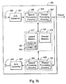
- FIG. 1b is a schematic block diagram illustrating several variations of an exemplary communication device employing the functionality of Fig. 1a.
- a communication device 151 comprises both a speech encoder and decoder for simultaneous capture and reproduction of speech.
- the communication device 151 might, for example, comprise a cellular telephone, portable telephone, computing system, etc.
- the communication device 151 might, for example, comprise a cellular telephone, portable telephone, computing system, etc.
- the communication device 151 might comprise an answering machine, a recorder, voice mail system, etc.
- a microphone 155 and an A/D converter 157 coordinate to deliver a digital voice signal to an encoding system 159.
- the encoding system 159 performs speech and channel encoding and delivers resultant speech information to the channel.
- the delivered speech information may be destined for another communication device (not shown) at a remote location.
- a decoding system 165 performs channel and speech decoding then coordinates with a D/A converter 167 and a speaker 169 to reproduce something that sounds like the originally captured speech.
- the encoding system 159 comprises both a speech processing circuit 185 that performs speech encoding, and a channel processing circuit 187 that performs channel encoding.
- the decoding system 165 comprises a speech processing circuit 189 that performs speech decoding, and a channel processing circuit 191 that performs channel decoding.
- the speech processing circuit 185 and the channel processing circuit 187 are separately illustrated, they might be combined in part or in total into a single unit.
- the speech processing circuit 185 and the channel processing circuitry 187 might share a single DSP (digital signal processor) and/or other processing circuitry.
- the speech processing circuit 189 and the channel processing circuit 191 might be entirely separate or combined in part or in whole.
- combinations in whole or in part might be applied to the speech processing circuits 185 and 189, the channel processing circuits 187 and 191, the processing circuits 185, 187, 189 and 191, or otherwise.
- the encoding system 159 and the decoding system 165 both utilize a memory 161.
- the speech processing circuit 185 utilizes a fixed codebook 181 and an adaptive codebook 183 of a speech memory 177 in the source encoding process.
- the channel processing circuit 187 utilizes a channel memory 175 to perform channel encoding.
- the speech processing circuit 189 utilizes the fixed codebook 181 and the adaptive codebook 183 in the source decoding process.
- the channel processing circuit 187 utilizes the channel memory 175 to perform channel decoding.
- the speech memory 177 is shared as illustrated, separate copies thereof can be assigned for the processing circuits 185 and 189. Likewise, separate channel memory can be allocated to both the processing circuits 187 and 191.
- the memory 161 also contains software utilized by the processing circuits 185,187,189 and 191 to perform various functionality required in the source and channel encoding and decoding processes.
- Figs. 2-4 are functional block diagrams illustrating a multi-step encoding approach used by one embodiment of the speech encoder illustrated in Figs. 1a and 1b.
- Fig. 2 is a functional block diagram illustrating of a first stage of operations performed by one embodiment of the speech encoder shown in Figs. 1a and 1b.
- the speech encoder which comprises encoder processing circuitry, typically operates pursuant to software instruction carrying out the following functionality.
- source encoder processing circuitry performs high pass filtering of a speech signal 211.
- the filter uses a cutoff frequency of around 80 Hz to remove, for example, 60 Hz power line noise and other lower frequency signals.
- the source encoder processing circuitry applies a perceptual weighting filter as represented by a block 219.
- the perceptual weighting filter operates to emphasize the valley areas of the filtered speech signal.
- a pitch preprocessing operation is performed on the weighted speech signal at a block 225.
- the pitch preprocessing operation involves warping the weighted speech signal to match interpolated pitch values that will be generated by the decoder processing circuitry.
- the warped speech signal is designated a first target signal 229. If pitch preprocessing is not selected the control block 245, the weighted speech signal passes through the block 225 without pitch preprocessing and is designated the first target signal 229.
- the encoder processing circuitry applies a process wherein a contribution from an adaptive codebook 257 is selected along with a corresponding gain 257 which minimize a first error signal 253.
- the first error signal 253 comprises the difference between the first target signal 229 and a weighted, synthesized contribution from the adaptive codebook 257.
- the resultant excitation vector is applied after adaptive gain reduction to both a synthesis and a weighting filter to generate a modeled signal that best matches the first target signal 229.
- the encoder processing circuitry uses LPC (linear predictive coding) analysis, as indicated by a block 239, to generate filter parameters for the synthesis and weighting filters.
- LPC linear predictive coding
- the encoder processing circuitry designates the first error signal 253 as a second target signal for matching using contributions from a fixed codebook 261.
- the encoder processing circuitry searches through at least one of the plurality of subcodebooks within the fixed codebook 261 in an attempt to select a most appropriate contribution while generally attempting to match the second target signal.
- the encoder processing circuitry selects an excitation vector, its corresponding subcodebook and gain based on a variety of factors. For example, the encoding bit rate, the degree of minimization, and characteristics of the speech itself as represented by a block 279 are considered by the encoder processing circuitry at control block 275. Although many other factors may be considered, exemplary characteristics include speech classification, noise level, sharpness, periodicity, etc. Thus, by considering other such factors, a first subcodebook with its best excitation vector may be selected rather than a second subcodebook's best excitation vector even though the second subcodebook's better minimizes the second target signal 265.
- Fig. 3 is a functional block diagram depicting of a second stage of operations performed by the embodiment of the speech encoder illustrated in Fig. 2.
- the speech encoding circuitry simultaneously uses both the adaptive the fixed codebook vectors found in the first stage of operations to minimize a third error signal 311.
- the speech encoding circuitry searches for optimum gain values for the previously identified excitation vectors (in the first stage) from both the adaptive and fixed codebooks 257 and 261. As indicated by blocks 307 and 309, the speech encoding circuitry identifies the optimum gain by generating a synthesized and weighted signal, i.e., via a block 301 and 303, that best matches the first target signal 229 (which minimizes the third error signal 311).
- the first and second stages could be combined wherein joint optimization of both gain and adaptive and fixed codebook rector selection could be used.
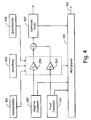
- Fig. 4 is a functional block diagram depicting of a third stage of operations performed by the embodiment of the speech encoder illustrated in Figs. 2 and 3.
- the encoder processing circuitry applies gain normalization, smoothing and quantization, as represented by blocks 401, 403 and 405, respectively, to the jointly optimized gains identified in the second stage of encoder processing.
- the adaptive and fixed codebook vectors used are those identified in the first stage processing.
- the encoder processing circuitry With normalization, smoothing and quantization functionally applied, the encoder processing circuitry has completed the modeling process. Therefore, the modeling parameters identified are communicated to the decoder.
- the encoder processing circuitry delivers an index to the selected adaptive codebook vector to the channel encoder via a multiplexor 419.
- the encoder processing circuitry delivers the index to the selected fixed codebook vector, resultant gains, synthesis filter parameters, etc., to the muliplexor 419.
- the multiplexor 419 generates a bit stream 421 of such information for delivery to the channel encoder for communication to the channel and speech decoder of receiving device.
- Fig. 5 is a block diagram of an embodiment illustrating functionality of speech decoder having corresponding functionality to that illustrated in Figs. 2-4.
- the speech decoder which comprises decoder processing circuitry, typically operates pursuant to software instruction carrying out the following functionality.
- a demultiplexor 511 receives a bit stream 513 of speech modeling indices from an often remote encoder via a channel decoder. As previously discussed, the encoder selected each index value during the multi-stage encoding process described above in reference to Figs. 2-4.
- the decoder processing circuitry utilizes indices, for example, to select excitation vectors from an adaptive codebook 515 and a fixed codebook 519, set the adaptive and fixed codebook gains at a block 521, and set the parameters for a synthesis filter 531.
- the decoder processing circuitry With such parameters and vectors selected or set, the decoder processing circuitry generates a reproduced speech signal 539.
- the codebooks 515 and 519 generate excitation vectors identified by the indices from the demultiplexor 511.
- the decoder processing circuitry applies the indexed gains at the block 521 to the vectors which are summed.
- the decoder processing circuitry modifies the gains to emphasize the contribution of vector from the adaptive codebook 515.
- adaptive tilt compensation is applied to the combined vectors with a goal of flattening the excitation spectrum.
- the decoder processing circuitry performs synthesis filtering at the block 531 using the flattened excitation signal.
- post filtering is applied at a block 535 deemphasizing the valley areas of the reproduced speech signal 539 to reduce the effect of distortion.
- the A/D converter 115 (Fig. 1a) will generally involve analog to uniform digital PCM including: 1) an input level adjustment device; 2) an input anti-aliasing filter; 3) a sample-hold device sampling at 8 kHz; and 4) analog to uniform digital conversion to 13-bit representation.
- the D/A converter 135 will generally involve uniform digital PCM to analog including: 1) conversion from 13-bit/8 kHz uniform PCM to analog; 2) a hold device; 3) reconstruction filter including x/sin(x) correction; and 4) an output level adjustment device.
- the A/D function may be achieved by direct conversion to 13-bit uniform PCM format, or by conversion to 8-bit/A-law compounded format.
- the inverse operations take place.
- the encoder 117 receives data samples with a resolution of 13 bits left justified in a 16-bit word. The three least significant bits are set to zero.
- the decoder 133 outputs data in the same format. Outside the speech codec, further processing can be applied to accommodate traffic data having a different representation.
- a specific embodiment of an AMR (adaptive multi-rate) codec with the operational functionality illustrated in Figs. 2-5 uses five source codecs with bit-rates 11.0, 8.0, 6.65, 5.8 and 4.55 kbps. Four of the highest source coding bit-rates are used in the full rate channel and the four lowest bit-rates in the half rate channel.
- All five source codecs within the AMR codec are generally based on a code-excited linear predictive (CELP) coding model.
- a long-term filter i.e., the pitch synthesis filter
- the excitation signal at the input of the short-term LP synthesis filter at the block 249 is constructed by adding two excitation vectors from the adaptive and the fixed codebooks 257 and 261, respectively.
- the speech is synthesized by feeding the two properly chosen vectors from these codebooks through the short-term synthesis filter at the block 249 and 267, respectively.
- the optimum excitation sequence in a codebook is chosen using an analysis-by-synthesis search procedure in which the error between the original and synthesized speech is minimized according to a perceptually weighted distortion measure.
- the weighting filter e.g., at the blocks 251 and 268, uses the unquantized LP parameters while the formant synthesis filter. e.g.. at the blocks 249 and 267, uses the quantized LP parameters. Both the unquantized and quantized LP parameters are generated at the block 239.
- the present encoder embodiment operates on 20 ms (millisecond) speech frames corresponding to 160 samples at the sampling frequency of 8000 samples per second.
- the speech signal is analyzed to extract the parameters of the CELP model, i.e., the LP filter coefficients, adaptive and fixed codebook indices and gains. These parameters are encoded and transmitted.
- these parameters are decoded and speech is synthesized by filtering the reconstructed excitation signal through the LP synthesis filter.
- LP analysis at the block 239 is performed twice per frame but only a single set of LP parameters is converted to line spectrum frequencies (LSF) and vector quantized using predictive multi-stage quantization (PMVQ).
- LSF line spectrum frequencies
- PMVQ predictive multi-stage quantization
- the speech frame is divided into subframes. Parameters from the adaptive and fixed codebooks 257 and 261 are transmitted every subframe. The quantized and unquantized LP parameters or their interpolated versions are used depending on the subframe.
- An open-loop pitch lag is estimated at the block 241 once or twice per frame for PP mode or LTP mode, respectively.
- the encoder processing circuitry (operating pursuant to software instruction) computes x(n), the first target signal 229, by filtering the LP residual through the weighted synthesis filter W(z)H(z) with the initial states of the filters having been updated by filtering the error between LP residual and excitation. This is equivalent to an alternate approach of subtracting the zero input response of the weighted synthesis filter from the weighted speech signal.
- the encoder processing circuitry computes the impulse response. h ( n ), of the weighted synthesis filter.
- closed-loop pitch analysis is performed to find the pitch lag and gain, using the first target signal 229, x(n), and impulse response. h(n), by searching around the open-loop pitch lag. Fractional pitch with various sample resolutions are used.
- the input original signal has been pitch-preprocessed to match the interpolated pitch contour, so no closed-loop search is needed.
- the LTP excitation vector is computed using the interpolated pitch contour and the past synthesized excitation.
- the encoder processing circuitry generates a new target signal x 2 (n), the second target signal 253, by removing the adaptive codebook contribution (filtered adaptive code vector) from x ( n ).
- the encoder processing circuitry uses the second target signal 253 in the fixed codebook search to find the optimum innovation.
- the gains of the adaptive and fixed codebook are scalar quantized with 4 and 5 bits respectively (with moving average prediction applied to the fixed codebook gain).
- the gains of the adaptive and fixed codebook are vector quantized (with moving average prediction applied to the fixed codebook gain).
- the filter memories are updated using the determined excitation signal for finding the first target signal in the next subframe.
- bit allocation of the AMR codec modes is shown in table 1. For example, for each 20 ms speech frame, 220, 160, 133 , 116 or 91 bits are produced, corresponding to bit rates of 11.0, 8.0, 6.65, 5.8 or 4.55 kbps, respectively.
- Table 1 Bit allocation of the AMR coding algorithm for 20 ms frame CODING RATE 11.0KBPS 8.0KBPS 6.65KBPS 5.80KBPS 4.55KBPS Frame size 20ms Look ahead 5ms LPC order 10 th -order Predictor for LSF 1 predictor: 2 predictors Quantization 0 bit/frame 1 bit/frame LSF Quantization 28 bit/frame 24 bit/frame 18 LPC interpolation 2 bits/frame 2 bits/f 0 2 bits/f 0 0 0 Coding mode bit 0 bit 0 bit bit bit/frame 0 bit 0 bit Pitch mode LTP LTP LTP PP PP PP Subframe size 5ms Pitch Lag 30 bits/frame (9696) 8585 8585 0008 0008 0008 Fixed excitation 31 bits/subframe 20 13 18 14 bits/subframe 10 bits/subframe Gain quantization 9 bits (scalar) 7 bits/subframe 6 bits/subframe Total 220 bits/frame 160 133 133 116 91
- the decoder processing circuitry pursuant to software control, reconstructs the speech signal using the transmitted modeling indices extracted from the received bit stream by the demultiplexor 511.
- the decoder processing circuitry decodes the indices to obtain the coder parameters at each transmission frame. These parameters are the LSF vectors, the fractional pitch lags, the innovative code vectors, and the two gains.
- the LSF vectors are converted to the LP filter coefficients and interpolated to obtain LP filters at each subframe.
- the decoder processing circuitry constructs the excitation signal by: 1) identifying the adaptive and innovative code vectors from the codebooks 515 and 519; 2) scaling the contributions by their respective gains at the block 521; 3) summing the scaled contributions; and 3) modifying and applying adaptive tilt compensation at the blocks 527 and 529.
- the speech signal is also reconstructed on a subframe basis by filtering the excitation through the LP synthesis at the block 531. Finally, the speech signal is passed through an adaptive post filter at the block 535 to generate the reproduced speech signal 539.
- the AMR encoder will produce the speech modeling information in a unique sequence and format, and the AMR decoder receives the same information in the same way.
- the different parameters of the encoded speech and their individual bits have unequal importance with respect to subjective quality. Before being submitted to the channel encoding function the bits are rearranged in the sequence of importance.
- Two pre-processing functions are applied prior to the encoding process: high-pass filtering and signal down-scaling.
- Down-scaling consists of dividing the input by a factor of 2 to reduce the possibility of overflows in the fixed point implementation.
- the high-pass filtering at the block 215 (Fig. 2) serves as a precaution against undesired low frequency components.
- H h l z 0.92727435 - 1.8544941 z - 1 + 0.92727435 z - 2 1 - 1.9059465 z - 1 + 0.9114024 z - 2
- Down scaling and high-pass filtering are combined by dividing the coefficients of the numerator of H hl ( z ) by 2.
- Short-term prediction, or linear prediction (LP) analysis is performed twice per speech frame using the autocorrelation approach with 30 ms windows. Specifically, two LP analyses are performed twice per frame using two different windows.
- LP_analysis_1 a hybrid window is used which has its weight concentrated at the fourth subframe.
- the hybrid window consists of two parts. The first part is half a Hamming window, and the second part is a quarter of a cosine cycle.
- LP_analysis_2 a symmetric Hamming window is used.
- LSFs Line Spectral Frequencies
- q 1 ( n ) is the interpolated LSF for subframe 1
- q 2 ( n ) is the LSF of subframe 2 obtained from LP_analysis_2 of current frame
- q 3 ( n ) is the interpolated LSF for subframe 3
- q 4 (n-1) is the LSF (cosine domain) from LP_analysis_1 of previous frame
- q 4 ( n ) is the LSF for subframe 4 obtained from LP_analysis_1 of current frame.
- the interpolation is carried out in the cosine domain.
- a VAD Voice Activity Detection algorithm is used to classify input speech frames into either active voice or inactive voice frame (background noise or silence) at a block 235 (Fig. 2).
- the classification is based on four measures: 1) speech sharpness P1_SHP; 2) normalized one delay correlation P2_R1; 3) normalized zero-crossing rate P3_ZC; and 4) normalized LP residual energy P4_RE.
- the voiced/unvoiced decision is derived if the following conditions are met:
- n m defines the location of this signal on the first half frame or the last half frame.
- a delay, k l among the four candidates, is selected by maximizing the four normalized correlations.
- k i is probably corrected to k i ( i ⁇ l ) by favoring the lower ranges.
- the final selected pitch lag is denoted by T op .
- LTP_mode long-term prediction
- LTP_mode is set to 0 at all times.
- LTP_mode is set to 1 all of the time.
- the encoder decides whether to operate in the LTP or PP mode. During the PP mode, only one pitch lag is transmitted per coding frame.
- the decision algorithm is as follows. First, at the block 241. a prediction of the pitch lag pit for the current frame is determined as follows:
- One frame is divided into 3 subframes for the long-term preprocessing.
- the subframe size, L s is 53
- the subframe size for searching, L sr is 70.
- L s is 54
- the local integer shifting range [SR0, SR1] for searching for the best local delay is computed as the following:
- the optimal fractional delay index, j opt is selected by maximizing R f ( j ).
- ⁇ opt the best local delay at the end of the current processing subframe.
- ⁇ o p t k r - 0.75 + 0.1 j o p t
- the accumulated delay at the end of the current subframe is renewed by: ⁇ a c c ⁇ ⁇ a c c + ⁇ o p t .
- the LSFs Prior to quantization the LSFs are smoothed in order to improve the perceptual quality. In principle, no smoothing is applied during speech and segments with rapid variations in the spectral envelope. During non-speech with slow variations in the spectral envelope, smoothing is applied to reduce unwanted spectral variations. Unwanted spectral variations could typically occur due to the estimation of the LPC parameters and LSF quantization. As an example, in stationary noise-like signals with constant spectral envelope introducing even very small variations in the spectral envelope is picked up easily by the human ear and perceived as an annoying modulation.
- lsf_est, (n) is the i th estimated LSF of frame n
- Isf i ( n ) is the i th LSF for quantization of frame n.
- the parameter ⁇ ( n ) controls the amount of smoothing, e.g. if ⁇ ( n ) is zero no smoothing is applied.
- ⁇ ( n ) is calculated from the VAD information (generated at the block 235) and two estimates of the evolution of the spectral envelope.
- the parameter ⁇ ( n ) is controlled by the following logic: where k 1 is the first reflection coefficient.
- step 1 the encoder processing circuitry checks the VAD and the evolution of the spectral envelope, and performs a full or partial reset of the smoothing if required.
- step 2 the encoder processing circuitry updates the counter, N mode_frm (n), and calculates the smoothing parameter, ⁇ ( n ).
- the parameter ⁇ ( n ) varies between 0.0 and 0.9, being 0.0 for speech, music, tonal-like signals, and non-stationary background noise and ramping up towards 0.9 when stationary background noise occurs.
- a vector of mean values is subtracted from the LSFs, and a vector of prediction error vector fe is calculated from the mean removed LSFs vector, using a full-matrix AR(2) predictor.
- a single predictor is used for the rates 5.8, 6.65, 8.0, and 11.0 kbps coders, and two sets of prediction coefficients are tested as possible predictors for the 4.55 kbps coder.
- the vector of prediction error is quantized using a multi-stage VQ, with multi-surviving candidates from each stage to the next stage.
- the two possible sets of prediction error vectors generated for the 4.55 kbps coder are considered as surviving candidates for the first stage.
- the first 4 stages have 64 entries each, and the fifth and last table have 16 entries.
- the first 3 stages are used for the 4.55 kbps coder, the first 4 stages are used for the 5.8, 6.65 and 8.0 kbps coders, and all 5 stages are used for the 11.0 kbps coder.
- the following table summarizes the number of bits used for the quantization of the LSFs for each rate.
- the code vector with index k min which minimizes ⁇ k such that ⁇ k max ⁇ ⁇ k for all k is chosen to represent the prediction/quantization error ( fe represents in this equation both the initial prediction error to the first stage and the successive quantization error from each stage to the next one).
- the final choice of vectors from all of the surviving candidates (and for the 4.55 kbps coder - also the predictor) is done at the end, after the last stage is searched, by choosing a combined set of vectors (and predictor) which minimizes the total error.
- the contribution from all of the stages is summed to form the quantized prediction error vector, and the quantized prediction error is added to the prediction states and the mean LSFs value to generate the quantized LSFs vector.
- the quantized LSFs are ordered and spaced with a minimal spacing of 50 Hz.
- q ⁇ 4 ( n -1) and q ⁇ 4 ( n ) are the cosines of the quantized LSF sets of the previous and current frames, respectively, and q ⁇ 1 ( n ), q ⁇ 2 ( n ) and q ⁇ 3 ( n ) are the interpolated LSF
- LTP_mode If the LTP_mode is 1, a search of the best interpolation path is performed in order to get the interpolated LSF sets.
- the search is based on a weighted mean absolute difference between a reference LSF set rl ⁇ ( n ) and the LSF set obtained from LP analysis_2 l ⁇ ( n ).
- the impulse response h ( n ) is computed by filtering the vector of coefficients of the filter A ( z / ⁇ 1 ) extended by zeros through the two filters 1/ A ⁇ ( z ) and 1/ A ( z / ⁇ 2 ).
- the target signal for the search of the adaptive codebook 257 is usually computed by subtracting the zero input response of the weighted synthesis filter H ( z ) W ( z ) from the weighted speech signal s w ( n ). This operation is performed on a frame basis.
- An equivalent procedure for computing the target signal is the filtering of the LP residual signal r ( n ) through the combination of the synthesis filter 1/ A ⁇ ( z ) and the weighting filter W (z).
- the initial states of these filters are updated by filtering the difference between the LP residual and the excitation.
- the residual signal r(n) which is needed for finding the target vector is also used in the adaptive codebook search to extend the past excitation buffer. This simplifies the adaptive codebook search procedure for delays less than the subframe size of 40 samples.
- the past synthesized excitation is memorized in ⁇ ext(MAX_LAG+n), n ⁇ 0 ⁇ , which is also called adaptive codebook.
- Adaptive codebook searching is performed on a subframe basis. It consists of performing closed-loop pitch lag search, and then computing the adaptive code vector by interpolating the past excitation at the selected fractional pitch lag.
- the LTP parameters (or the adaptive codebook parameters) are the pitch lag (or the delay) and gain of the pitch filter.
- the excitation is extended by the LP residual to simplify the closed-loop search.
- the pitch delay is encoded with 9 bits for the 1 st and 3 rd subframes and the relative delay of the other subframes is encoded with 6 bits.
- a fractional pitch delay is used in the first and third subframes with resolutions: 1/6 in the range 17 , 93 4 6 , and integers only in the range [95,145].
- a pitch resolution of 1/6 is always used for the rate 11.0 kbps in the range T 1 - 5 3 6 , T 1 + 4 3 6 , where T 1 is the pitch lag of the previous (1 st or 3 rd ) subframe.
- the LP residual is copied to u ( n ) to make the relation in the calculations valid for all delays.
- the adaptive codebook vector, v ( n ) is computed by interpolating the past excitation u ( n ) at the given phase (fraction). The interpolations are performed using two FIR filters (Hamming windowed sinc functions), one for interpolating the term in the calculations to find the fractional pitch lag and the other for interpolating the past excitation as previously described.
- the adaptive codebook gain, g p is the adaptive codebook gain
- y ( n ) v ( n ) * h ( n ) is the filtered adaptive codebook vector (zero state response of H ( z ) W ( z ) to v ( n )).
- the adaptive codebook gain could be modified again due to joint optimization of the gains, gain normalization and smoothing.
- y ( n ) is also referred to herein as C p (n).
- pitch lag maximizing correlation might result in two or more times the correct one.
- the candidate of shorter pitch lag is favored by weighting the correlations of different candidates with constant weighting coefficients. At times this approach does not correct the double or treble pitch lag because the weighting coefficients are not aggressive enough or could result in halving the pitch lag due to the strong weighting coefficients.
- these weighting coefficients become adaptive by checking if the present candidate is in the neighborhood of the previous pitch lags (when the previous frames are voiced) and if the candidate of shorter lag is in the neighborhood of the value obtained by dividing the longer lag (which maximizes the correlation) with an integer.
- a speech classifier is used to direct the searching procedure of the fixed codebook (as indicated by the blocks 275 and 279) and to-control gain normalization (as indicated in the block 401 of Fig. 4).
- the speech classifier serves to improve the background noise performance for the lower rate coders, and to get a quick start-up of the noise level estimation.
- the speech classifier distinguishes stationary noise-like segments from segments of speech, music, tonal-like signals, non-stationary noise, etc.
- the speech classification is performed in two steps.
- An initial classification ( speech_mode ) is obtained based on the modified input signal.
- the final classification (exc_mode) is obtained from the initial classification and the residual signal after the pitch contribution has been removed.
- the two outputs from the speech classification are the excitation mode, exc_mode, and the parameter ⁇ sub ( n ), used to control the subframe based smoothing of the gains.
- the speech classification is used to direct the encoder according to the characteristics of the input signal and need not be transmitted to the decoder.
- the encoder emphasizes the perceptually important features of the input signal on a subframe basis by adapting the encoding in response to such features. It is important to notice that misclassification will not result in disastrous speech quality degradations.
- the speech classifier identified within the block 279 (Fig. 2) is designed to be somewhat more aggressive for optimal perceptual quality.
- the initial classifier ( speech_classifier ) has adaptive thresholds and is performed in six steps:
- the final classifier ( exc_preselect ) provides the final class, exc_mode, and the subframe based smoothing parameter, ⁇ sub ( n ). It has three steps:
- a fast searching approach is used to choose a subcodebook and select the code word for the current subframe.
- the same searching routine is used for all the bit rate modes with different input parameters.
- the long-term enhancement filter, F P ( z ) is used to filter through the selected pulse excitation.
- the impulsive response h(n) includes the filter Fp(z).
- Gaussian subcodebooks For the Gaussian subcodebooks, a special structure is used in order to bring down the storage requirement and the computational complexity. Furthermore, no pitch enhancement is applied to the Gaussian subcodebooks.
- All pulses have the amplitudes of +1 or -1. Each pulse has 0, 1, 2, 3 or 4 bits to code the pulse position.
- the signs of some pulses are transmitted to the decoder with one bit coding one sign.
- the signs of other pulses are determined in a way related to the coded signs and their pulse positions.
- each pulse has 3 or 4 bits to code the pulse position.
- At least the first sign for the first pulse, SIGN(n p ), np 0, is encoded because the gain sign is embedded.
- the innovation vector contains 10 signed pulses. Each pulse has 0, 1, or 2 bits to code the pulse position.
- One subframe with the size of 40 samples is divided into 10 small segments with the length of 4 samples.
- 10 pulses are respectively located into 10 segments. Since the position of each pulse is limited into one segment, the possible locations for the pulse numbered with n p are, ⁇ 4n p ⁇ , ⁇ 4n p , 4n p +2 ⁇ , or [4n p , 4n p +1, 4n p +2, 4n p +3 ⁇ , respectively for 0, 1, or 2 bits to code the pulse position. All the signs for all the 10 pulses are encoded.
- the fixed codebook 261 is searched by minimizing the mean square error between the weighted input speech and the weighted synthesized speech.
- c k is the code vector at index k from the fixed codebook
- the pulse codebook is searched by maximizing the term:
- a k C k 2 E
- D k d t c k 2 c k t ⁇ c k
- d H t x 2 is the correlation between the target signal x 2 ( n ) and the impulse response h ( n )
- H is a the lower triangular Toepliz convolution matrix with diagonal h (0) and lower diagonals h (1),..., h (39)
- ⁇ H t H is the matrix of correlations of h ( n ).
- the vector d (backward filtered target) and the matrix ⁇ are computed prior to the codebook search.
- the pulse signs are preset by using the signal b(n), which is a weighted sum of the normalized d(n) vector and the normalized target signal of x 2 (n) in the residual domain res 2 (n) :
- the encoder processing circuitry corrects each pulse position sequentially from the first pulse to the last pulse by checking the criterion value A k contributed from all the pulses for all possible locations of the current pulse.
- the functionality of the second searching turn is repeated a final time.
- further turns may be utilized if the added complexity is not prohibitive.
- the above searching approach proves very efficient, because only one position of one pulse is changed leading to changes in only one term in the criterion numerator C and few terms in the criterion denominator E D for each computation of the A k .
- one of the subcodebooks in the fixed codebook 261 is chosen after finishing the first searching turn. Further searching turns are done only with the chosen subcodebook. In other embodiments, one of the subcodebooks might be chosen only after the second searching turn or thereafter should processing resources so permit.
- the Gaussian codebook is structured to reduce the storage requirement and the computational complexity.
- a comb-structure with two basis vectors is used.
- the basis vectors are orthogonal, facilitating a low complexity search.
- the first basis vector occupies the even sample positions, (0.2,...,38).
- the second basis vector occupies the odd sample positions, (1,3,...,39).
- the same codebook is used for both basis vectors, and the length of the codebook vectors is 20 samples (half the subframe size).
- each entry in the Gaussian table can produce as many as 20 unique vectors, all with the same energy due to the circular shift.
- the search of the Gaussian codebook utilizes the structure of the codebook to facilitate a low complexity search. Initially, the candidates for the two basis vectors are searched independently based on the ideal excitation, res 2 . For each basis vector, the two best candidates, along with the respective signs, are found according to the mean squared error.
- the remaining parameters are explained above.
- the total number of entries in the Gaussian codebook is 2 ⁇ 2 ⁇ N Gauss 2 .
- the fine search minimizes the error between the weighted speech and the weighted synthesized speech considering the possible combination of candidates for the two basis vectors from the preselection.
- two subcodebooks are included (or utilized) in the fixed codebook 261 with 31 bits in the 11 kbps encoding mode.
- the innovation vector contains 8 pulses. Each pulse has 3 bits to code the pulse position. The signs of 6 pulses are transmitted to the decoder with 6 bits.
- the second subcodebook contains innovation vectors comprising 10 pulses. Two bits for each pulse are assigned to code the pulse position which is limited in one of the 10 segments. Ten bits are spent for 10 signs of the 10 pulses.
- the bit allocation for the subcodebooks used in the fixed codebook 261 can be summarized as follows:
- One of the two subcodebooks is chosen at the block 275 (Fig. 2) by favoring the second subcodebook using adaptive weighting applied when comparing the criterion value F1 from the first subcodebook to the criterion value F2 from the second subcodebook:
- the innovation vector contains 4 pulses. Each pulse has 4 bits to code the pulse position. The signs of 3 pulses are transmitted to the decoder with 3 bits.
- the second subcodebook contains innovation vectors having 10 pulses. One bit for each of 9 pulses is assigned to code the pulse position which is limited in one of the 10 segments. Ten bits are spent for 10 signs of the 10 pulses.
- the bit allocation for the subcodebook can be summarized as the following:
- the 6.65kbps mode operates using the long-term preprocessing (PP) or the traditional LTP.
- PP long-term preprocessing
- a pulse subcodebook of 18 bits is used when in the PP-mode.
- a total of 13 bits are allocated for three subcodebooks when operating in the LTP-mode.
- the bit allocation for the subcodebooks can be summarized as follows:
- the 5.8 kbps encoding mode works only with the long-term preprocessing (PP).
- Total 14 bits are allocated for three subcodebooks.
- the bit allocation for the subcodebooks can be summarized as the following:
- the 4.55 kbps bit rate mode works only with the long-term preprocessing (PP). Total 10 bits are allocated for three subcodebooks.
- the bit allocation for the subcodebooks can be summarized as the following:
- a gain re-optimization procedure is performed to jointly optimize the adaptive and fixed codebook gains, g p and g c , respectively, as indicated in Fig. 3.
- C ⁇ c , C ⁇ p , and T ⁇ gs are filtered fixed codebook excitation, filtered adaptive codebook excitation and the target signal for the adaptive codebook search.
- the adaptive codebook gain, g p remains the same as that computed in the closeloop pitch search.
- Original CELP algorithm is based on the concept of analysis by synthesis (waveform matching). At low bit rate or when coding noisy speech, the waveform matching becomes difficult so that the gains are up-down, frequently resulting in unnatural sounds. To compensate for this problem, the gains obtained in the analysis by synthesis close-loop sometimes need to be modified or normalized.
- the gain normalization factor is a linear combination of the one from the close-loop approach and the one from the open-loop approach; the weighting coefficients used for the combination are controlled according to the LPC gain.
- the decision to do the gain normalization is made if one of the following conditions is met: (a) the bit rate is 8.0 or 6.65 kbps, and noise-like unvoiced speech is true; (b) the noise level P NSR is larger than 0.5; (c) the bit rate is 6.65 kbps, and the noise level P NSR is larger than 0.2; and (d) the bit rate is 5.8 or 4.45kbps.
- the final gain normalization factor, g f is a combination of Cl_g and Ol_g, controlled in terms of an LPC gain parameter, C LPC ,
- the adaptive codebook gain and the fixed codebook gain are vector quantized using 6 bits for rate 4.55 kbps and 7 bits for the other rates.
- scalar quantization is performed to quantize both the adaptive codebook gain, g p , using 4 bits and the fixed codebook gain, g c , using 5 bits each.
- the fixed codebook gain, g c is obtained by MA prediction of the energy of the scaled fixed codebook excitation in the following manner.
- the codebook search for 4.55, 5.8, 6.65 and 8.0 kbps encoding bit rates consists of two steps.
- a binary search of a single entry table representing the quantized prediction error is performed.
- the index Index_ 1 of the optimum entry that is closest to the unquantized prediction error in mean square error sense is used to limit the search of the two-dimensional VQ table representing the adaptive codebook gain and the prediction error.
- a fast search using few candidates around the entry pointed by Index_ 1 is performed. In fact, only about half of the VQ table entries are tested to lead to the optimum entry with Index_ 2. Only Index_ 2 is transmitted.
- a full search of both scalar gain codebooks are used to quantize g p and g c .
- the state of the filters can be updated by filtering the signal r ( n ) - u ( n ) through the filters 1/ A ⁇ ( z ) and W ( z ) for the 40-sample subframe and saving the states of the filters. This would normally require 3 filterings.
- the function of the decoder consists of decoding the transmitted parameters (dLP parameters, adaptive codebook vector and its gain, fixed codebook vector and its gain) and performing synthesis to obtain the reconstructed speech.
- the reconstructed speech is then postfiltered and upscaled.
- the decoding process is performed in the following order.
- the LP filter parameters are encoded.
- the received indices of LSF quantization are used to reconstruct the quantized LSF vector.
- Interpolation is performed to obtain 4 interpolated LSF vectors (corresponding to 4 subframes).
- the interpolated LSF vector is converted to LP filter coefficient domain, a k , which is used for synthesizing the reconstructed speech in the subframe.
- the received pitch index is used to interpolate the pitch lag across the entire subframe. The following three steps are repeated for each subframe:
- Adaptive gain control is used to compensate for the gain difference between the unemphasized excitation u ( n ) and emphasized excitation u ⁇ ( n ).
- the synthesized speech s ⁇ ( n ) is then passed through an adaptive postfilter.
- Post-processing consists of two functions: adaptive postfiltering and signal up-scaling.
- the adaptive postfilter is the cascade of three filters: a formant postfilter and two tilt compensation filters.
- the postfilter is updated every subframe of 5 ms.
- the postfiltering process is performed as follows. First, the synthesized speech s ⁇ ( n ) is inverse filtered through A ⁇ / ⁇ n z to produce the residual signal r ⁇ ( n ) .
- the signal r ⁇ ( n ) is filtered by the synthesis filter 1/ A ⁇ ( z / ⁇ d ) is passed to the first tilt compensation filter h r 1 ( z ) resulting in the postfiltered speech signal s ⁇ f ( n ).
- Adaptive gain control is used to compensate for the gain difference between the synthesized speech signal s ⁇ ( n ) and the postfiltered signal s ⁇ f ( n ) .
- up-scaling consists of multiplying the postfiltered speech by a factor 2 to undo the down scaling by 2 which is applied to the input signal.
- Figs. 6 and 7 are drawings of an alternate embodiment of a 4 kbps speech codec that also illustrates various aspects of the present invention.
- Fig. 6 is a block diagram of a speech encoder 601 that is built in accordance with the present invention.
- the speech encoder 601 is based on the analysis-by-synthesis principle. To achieve toll quality at 4 kbps, the speech encoder 601 departs from the strict waveform-matching criterion of regular CELP coders and strives to catch the perceptual important features of the input signal.
- the speech encoder 601 operates on a frame size of 20 ms with three subframes (two of 6.625 ms and one of 6.75 ms). A look-ahead of 15 ms is used. The one-way coding delay of the codec adds up to 55 ms.
- the spectral envelope is represented by a 10 th order LPC analysis for each frame.
- the prediction coefficients are transformed to the Line Spectrum Frequencies (LSFs) for quantization.
- LSFs Line Spectrum Frequencies
- the input signal is modified to better fit the coding model without loss of quality. This processing is denoted "signal modification" as indicated by a block 621.
- signal modification In order to improve the quality of the reconstructed signal, perceptual important features are estimated and emphasized during encoding.
- the excitation signal for an LPC synthesis filter 625 is build from the two traditional components: 1) the pitch contribution; and 2) the innovation contribution.
- the pitch contribution is provided through use of an adaptive codebook 627.
- An innovation codebook 629 has several subcodebooks in order to provide robustness against a wide range of input signals. To each of the two contributions a gain is applied which, multiplied with their respective codebook vectors and summed, provide the excitation signal.
- the LSFs and pitch lag are coded on a frame basis, and the remaining parameters (the innovation codebook index, the pitch gain, and the innovation codebook gain) are coded for every subframe.
- the LSF vector is coded using predictive vector quantization.
- the pitch lag has an integer part and a fractional part constituting the pitch period.
- the quantized pitch period has a non-uniform resolution with higher density of quantized values at lower delays.
- the bit allocation for the parameters is shown in the following table.
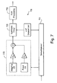
- Fig. 7 is a block diagram of a decoder 701 with corresponding functionality to that of the encoder of Fig. 6.
- the decoder 701 receives the 80 bits on a frame basis from a demultiplexor 711. Upon receipt of the bits, the decoder 701 checks the sync-word for a bad frame indication, and decides whether the entire 80 bits should be disregarded and frame erasure concealment applied. If the frame is not declared a frame erasure, the 80 bits are mapped to the parameter indices of the codec, and the parameters are decoded from the indices using the inverse quantization schemes of the encoder of Fig. 6.
- the excitation signal is reconstructed via a block 715.
- the output signal is synthesized by passing the reconstructed excitation signal through an LPC synthesis filter 721.
- LPC synthesis filter 721 To enhance the perceptual quality of the reconstructed signal both short-term and long-term post-processing are applied at a block 731.
- the LSFs and pitch lag are quantized with 21 and 8 bits per 20 ms, respectively. Although the three subframes are of different size the remaining bits are allocated evenly among them. Thus, the innovation vector is quantized with 13 bits per subframe. This adds up to a total of 80 bits per 20 ms, equivalent to 4 kbps.
- the estimated complexity numbers for the proposed 4 kbps codec are listed in the following table. All numbers are under the assumption that the codec is implemented on commercially available 16-bit fixed point DSPs in full duplex mode. All storage numbers are under the assumption of 16-bit words, and the complexity estimates are based on the floating point C-source code of the codec. Table of Complexity Estimates Computational complexity 30 MIPS Program and data ROM 18 kwords RAM 3 kwords
- the decoder 701 comprises decode processing circuitry that generally operates pursuant to software control.
- the encoder 601 (Fig. 6) comprises encoder processing circuitry also operating pursuant to software control.
- processing circuitry may coexists, at least in part, within a single processing unit such as a single DSP.
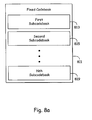
- FIG. 8a is a block diagram illustrating an embodiment of the speech encoding system in accordance with the present invention.
- a fixed codebook 811 comprises a first sub-codebook 813, a second sub-codebook 815 and may contain additional sub-codebooks up to an N th sub-codebook 819.
- Figure 8b is a flow diagram illustrating an exemplary method of finding then fixing pulse positions of a given pulse index as performed by a speech encoder built in accordance with the present invention.
- encoder processing circuitry operating pursuant to software direction begins the process of identifying the pulse positions at a block 831 by finding then fixing an initial pulse position.
- a subsequent pulse position is found and fixed at a block 835. Additional pulses are found and then fixed until the encoder processing circuitry compares the number of pulses to determine whether all of the pulses have been found and fixed at a block 839. If less than the total number of pulses has been processed, the encoder processing circuitry continues to find and fix pulses until all of the pulses have been processed.
- the speech processing circuitry determines whether the last turn of the search has been completed at a block 849. If additional turns of the search remain, the software direction restarts the process of finding then fixing the initial pulse position of an additional pulse index until all turns of the search have been completed.
- Figure 8c is a flow diagram providing a detailed description of a specific embodiment of the method of selecting the sub-codebooks of Figure 8a by employing the search method of Figure 8b.
- Encoder processing circuitry operating pursuant to software direction begins the process of selecting the sub-codebooks at a block 851 by selecting a first sub-codebook (SCB).
- SCB first sub-codebook
- the encoder processing circuitry begins the process of identifying the pulse positions of the first sub-codebook selected at a block 855 by finding then fixing an initial pulse position of the first sub-codebook.
- a subsequent pulse position is found and fixed at a block 859. Additional pulses are found and then fixed until the encoder processing circuitry compares the number of pulses to determine whether all of the pulses have been found and fixed at a block 863. If less than the total number of pulses has been processed, the encoder processing circuitry continues to find and fix pulses until all of the pulses have been processed.
- the encoder processing circuitry determines whether a specified number of turns has been completed at a block 867. If the specified number of turns has not been completed, the encoder processing circuitry determines whether the last SCB has been searched at a block 871.
- the encoder processing circuitry begins the process of identifying the pulse positions of the newly-selected SCB at block 855 by finding then fixing an initial pulse position of the newly-selected SCB.
- the encoder processing circuitry determines whether the best SCB has been selected at a block 879. If the best SCB has been selected, then the encoder processing circuitry determines whether the last turn has occurred at a block 883. If the last turn has not been completed, the encoder processing circuitry repeats the process of finding then fixing an initial position of the presently-selected SCB. If the best SCB has not been selected, then a best SCB is selected at a block 887, and then the encoder processing circuitry determines whether the last turn has been completed at block 883. If the last turn has been completed, then the method of selecting the sub-codebooks is complete.
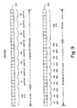
- Figure 9 demonstrates the codebook structure with two sub-codebooks in the 11 kbits/s mode.
- the excitation vector in the first sub-codebook SCB1 contains eight pulses of three bits each. Six bits are used to transmit the signs of six pulses to the decoder.
- the second sub-codebook SCB2 is coded with ten pulses of two bits each, with ten additional bits used for the signs of the ten pulses.
- Figure 10 demonstrates the codebook structure with two sub-codebooks in the 8 kbits/s mode.
- the excitation in the first sub-codebook SCB1 contains four pulses of four bits each, with three bits used to transmit the signs of three pulses.
- the second sub-codebook SCB 1 is coded with ten pulses, using one bit each for nine of the pulses with the pulse position limited in one of the ten bits. Ten additional bits are used for signs of the ten pulses.
- Figure 11a demonstrates the codebook structure when switched on the PP-mode in 6.65 kbits/s mode. Five pulses of three bits each are used along with three sign bits.
- three sub-codebooks are used, as shown in Figure 11b.
- the first sub-codebook SCB 1 contains three pulses of three bits each with three sign bits
- the second sub-codebook SCB2 contains three pulses of three bits each with two sign bits
- the third sub-codebook SCB3 contains eleven bits of Gaussian noise.
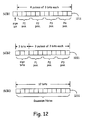
- Figure 12 demonstrates the codebook structure with three sub-codebooks in the 5.8 kbits/s mode.
- First sub-codebook SCB 1 contains four pulses of three bits each with one sign bit
- second sub-codebook SCB2 contains three pulses of three bits each with three sign bits
- sub-codebook SCB3 contains twelve bits of Gaussian noise.
- Figure 13 demonstrates the codebook structure with three sub-codebooks in the 4.44 kbits/s mode.
- First sub-codebook SCB1 contains two pulses of four bits each with one sign bit
- second sub-codebook SCB2 contains two pulses of three bits each with two sign bits
- sub-codebook SCB3 contains eight bits of Gaussian noise.
- Appendix A provides a list of many of the definitions, symbols and abbreviations used in this application.
- Appendices B and C respectively provide source and channel bit ordering information at various encoding bit rates used in one embodiment of the present invention. Appendices A, B and C comprise part of the detailed description of the present application.
- adaptive codebook contains excitation vectors that are adapted for every subframe.
- the adaptive codebook is derived from the long term filter state.
- the pitch lag value can be viewed as an index into the adaptive codebook.
- adaptive postfilter The adaptive postfilter is applied to the output of the short term synthesis filter to enhance the perceptual quality of the reconstructed speech.
- the adaptive postfilter is a cascade of two filters: a formant postfilter and a tilt compensation filter.
- the adaptive multi-rate code is a speech and channel codec capable of operating at gross bit-rates of 11.4 kbps ("half-rate") and 22.8 kbs ("full-rate”).
- the codec may operate at various combinations of speech and channel coding (codec mode) bit-rates for each channel mode.
- AMR handover Handover between the full rate and half rate channel modes to optimize AMR operation.
- channel mode Half-rate (HR) or full-rate (FR) operation.
- channel mode adaptation The control and selection of the (FR or HR) channel mode.
- channel repacking Repacking ofHR (and FR) radio channels of a given radio cell to achieve higher capacity within the cell.
- closed-loop pitch analysis This is the adaptive codebook search, i.e., a process of estimating the pitch (lag) value from the weighted input speech and the long term filter state.
- the lag is searched using error minimization loop (analysis-by-synthesis).
- closed-loop pitch search is performed for every subframe.
- codec mode For a given channel mode, the bit partitioning between the speech and channel codecs.
- codec mode adaptation The control and selection of the codec mode bit-rates. Normally, implies no change to the channel mode.
- direct form coefficients One of the formats for storing the short term filter parameters. In the adaptive multi rate codec, all filters used to modify speech samples use direct form coefficients.
- the fixed codebook contains excitation vectors for speech synthesis filters. The contents of the codebook are non-adaptive (i.e., fixed). In the adaptive multi rate codec, the fixed codebook for a specific rate is implemented using a multi-function codebook.
- fractional lags A set of lag values having sub-sample resolution. In the adaptive multi rate codec a sub-sample resolution between 1/6 th and 1.0 of a sample is used.
- Line Spectral Pairs are obtained by decomposing the inverse filter transfer function A(z) to a set of two transfer functions, one having even symmetry and the other having odd symmetry.
- the Line Spectral Pairs (also called as Line Spectral Frequencies) are the roots of these polynomials on the z-unit circle).
- LP analysis window For each frame, the short term filter coefficients are computed using the high pass filtered speech samples within the analysis window. In the adaptive multi rate codec, the length of the analysis window is always 240 samples. For each frame, two asymmetric windows are used to generate two sets of LP coefficient coefficients which are interpolated in the LSF domain to construct the perceptual weighting filter.
- LTP Mode Codec works with traditional LTP. mode: When used alone, refers to the source codec mode, i.e., to one of the source codecs employed in the AMR codec.
- multi-function codebook A fixed codebook consisting of several subcodebooks constructed with different kinds of pulse innovation vector structures and noise innovation vectors, where codeword from the codebook is used to synthesize the excitation vectors.
- open-loop pitch search A process of estimating the near optimal pitch lag directly from the weighted input speech. This is done to simplify the pitch analysis and confine the closed-loop pitch search to a small number of lags around the open-loop estimated lags. In the adaptive multi rate codec, open-loop pitch search is performed once per frame for PP mode and twice per frame for LTP mode.
- out-of-band signaling Signaling on the GSM control channels to support link control.
- PP Mode Codec works with pitch preprocessing.
- short term synthesis filter This filter introduces, into the excitation signal, short term correlation which models the impulse response of the vocal tract.
- perceptual weighting filter This filter is employed in the analysis-by-synthesis search of the codebooks. The filter exploits the noise masking properties of the formants (vocal tract resonances) by weighting the error less in regions near the formant frequencies and more in regions away from them.
- subframe A time interval equal to 5-10 ms (40-80 samples at an 8 kHz sampling rate).
- vector quantization A method of grouping several parameters into a vector and quantizing them simultaneously.
- zero input response The output of a filter due to past inputs, i.e.
- zero state response The output of a filter due to the present input, given that no past inputs have been applied, i.e., given the state information in the filter is all zeroes.
- Bit ordering of output bits from source encoder (11 kbit/s). Bits Description 1-6 Index of 1 st LSF stage 7-12 Index of 2 nd LSF stage 13-18 Index of 3 rd LSF stage 19-24 Index of 4 th LSF stage 25-28 Index of 5 th LSF stage 29-32 Index of adaptive codebook gain, 1 st subframe 33-37 index of fixed codebook gain, 1 st subframe 38-41 Index of adaptive codebook gain. 2 nd subframe 42-46 index of fixed codebook gain. 2 nd subframe 47-50 Index of adaptive codebook gain, 3 rd subframe 51-55 Index of fixed codebook gain. 3 rd subframe 56-59 Index of adaptive codebook gain.
- gain1-0 26 gain1-1 32 gain2-0 33 gain2-1 39 gain3-0 40 gain3-1 46 gain4-0 47 gain4-1 1 lsf1-0 2 lsf1-1 3 lsf1-2 4 Isf1-3 5 lsf1-4 6 lsf1-5 27 gain1-2 34 gain2-2 41 gain3-2 48 gain4-2 53 pitch-0 54 pitch-1 55 pitch-2 56 pitch-3 57 pitch-4 58 pitch-5 28 gain1-3 29 gain1-4 35 gain2-3 36 gain2-4 42 gain3-3 43 gain3-4 49 gain4-3 50 gain4-4 7 lsf2-0 8 lsf2-1 9 lsf2-2 10 lsf2-3 11 lsf2-4 12 lsf2-5 13 lsf3-0 14 lsf3-1 15 lsf3-2 16 lsf3-3 17 lsf3-4 18 lsf3-5 19 lsf4-0 20 lsf4-1 21 lsf4-2 22 lsf4-3 30 gain1-5 37 gain2-5 44 gain3-5 51 gain4-5
Description
- The present invention relates generally to speech encoding and decoding in mobile cellular communication networks; and, more particularly, it relates to various techniques of using sub-codebooks for pulse-like excitation in speech reproduction through a limited bit rate communication channel.
- Signal modeling and parameter estimation play significant roles in communicating voice information with limited bandwidth constraints. To model basic speech sounds, speech signals are sampled as a discrete waveform to be digitally processed. In one type of signal coding technique, called linear predictive coding (LPC), the signal value at any particular time index is modeled as a linear-function of previous values. A subsequent signal is thus linearly predictable according to an earlier value. As a result, efficient signal representations can be determined by estimating and applying certain prediction parameters to represent the signal.
- In speech encoding and decoding, it is well-known that pulse-like excitation provides better quality than noise-like excitation for voiced speech. Previously, exclusively pulse-like excitation was used with ACELP (Adaptive Code Excited Linear Predictive) systems in which codebooks with fixed numbers of pulses, fixed pulse position resolution and fixed pulse magnitude was utilized. Nevertheless, ACELP systems did not work well for certain types of speech signals.
- The present invention addresses these problems by recognizing that, depending on the circumstances, either the number of pulses or the pulse position resolution may be more important. Accordingly, sub-codebooks are designed in such a way that either frequency of pulses or pulse resolution can be emphasized.
- Further limitations and disadvantages of conventional systems will become apparent to one of skill in the art after reviewing the remainder of the present application with reference to the drawings.
- Salami et al ("Real-time implementation of a 9.6kbit/s ACELP wideband speech coder", Proc. Of Globecom 1992, vol. 1, pages 447-451) describes a speech coder implementation using an ACELP approach with two codebooks.
- Laflamme C et al: "16 kbps wideband speech coding technique based on algebraic CELP", ICASSP 1991, discloses a focused codebook search strategy.
- According to the invention, there are provided a speech encoder as set forth in
claim 1 and a method as set forth inclaim 8. Preferred embodiment are set forth in the dependent claims. -
- Fig. 1a is a schematic block diagram of a speech communication system illustrating the use of source encoding and decoding in accordance with the present invention.
- Fig. 1b is a schematic block diagram illustrating an exemplary communication device utilizing the source encoding and decoding functionality of Fig. 1a.
- Figs. 2-4 are functional block diagrams illustrating a multi-step encoding approach used by one embodiment of the speech encoder illustrated in Figs. 1 a and 1b. In particular, Fig. 2 is a functional block diagram illustrating of a first stage of operations performed by one embodiment of the speech encoder of Figs. 1a and 1b. Fig. 3 is a functional block diagram of a second stage of operations, while Fig. 4 illustrates a third stage.
- Fig. 5 is a block diagram of one embodiment of the speech decoder shown in Figs. 1a and 1b having corresponding functionality to that illustrated in Figs. 2-4.
- Fig. 6 is a block diagram of an alternate embodiment of a speech encoder that is built in accordance with the present invention.
- Fig. 7 is a block diagram of an embodiment of a speech decoder having corresponding functionality to that of the speech encoder of Fig. 6.
- Figure 8a is a block diagram illustrating an embodiment of the speech encoding system in accordance with the present invention.
- Figure 8b is a flow diagram illustrating an exemplary method of finding then fixing pulse positions of a given pulse index as performed by a speech encoder built in accordance with the present invention.
- Figure 8c is a flow diagram providing a detailed description of a specific embodiment of the method of selecting.the sub-codebooks of Figure 8a by employing the search method of Figure 8b.
- Figure 9 demonstrates the codebooks structure with two sub-codebooks in the 11 kbits/s mode.
- Figure 10 demonstrates the codebook structure with two sub-codebooks in the 8 kbits/s mode.
- Figure 11a demonstrates the codebook structure when switched on the PP-mode in 6.65 kbits/s mode.
- Figure 11b demonstrates the codebook structure when switched to the LPT-mode in the 6.65 kbits/s mode.
- Figure 12 demonstrates the codebook structure with three sub-codebooks in the 5.8 kbits/s mode.
- Finally, Figure 13 demonstrates the codebook structure with three sub-codebooks in the 4.44 kbits/s mode.
- Fig. la is a schematic block diagram of a speech communication system illustrating the use of source encoding and decoding in accordance with the present invention. Therein, a
speech communication system 100 supports communication and reproduction of speech across acommunication channel 103. Although it may comprise for example a wire, fiber or optical link, thecommunication channel 103 typically comprises, at least in part, a radio frequency link that often must support multiple, simultaneous speech exchanges requiring shared bandwidth resources such as may be found with cellular telephony embodiments. - Although not shown, a storage device may be coupled to the
communication channel 103 to temporarily store speech information for delayed reproduction or playback, e.g., to perform answering machine functionality, voiced email, etc. Likewise, thecommunication channel 103 might be replaced by such a storage device in a single device embodiment of thecommunication system 100 that, for example, merely records and stores speech for subsequent playback. - In particular, a
microphone 111 produces a speech signal in real time. Themicrophone 111 delivers the speech signal to an A/D (analog to digital)converter 115. The A/D converter 115 converts the speech signal to a digital form then delivers the digitized speech signal to aspeech encoder 117. - The
speech encoder 117 encodes the digitized speech by using a selected one of a plurality of encoding modes. Each of the plurality of encoding modes utilizes particular techniques that attempt to optimize quality of resultant reproduced speech. While operating in any of the plurality of modes, thespeech encoder 117 produces a series of modeling and parameter information (hereinafter "speech indices"), and delivers the speech indices to achannel encoder 119. - The
channel encoder 119 coordinates with achannel decoder 131 to deliver the speech indices across thecommunication channel 103. Thechannel decoder 131 forwards the speech indices to aspeech decoder 133. While operating in a mode that corresponds to that of thespeech encoder 117, thespeech decoder 133 attempts to recreate the original speech from the speech indices as accurately as possible at aspeaker 137 via a D/A (digital to analog)converter 135. - The
speech encoder 117 adaptively selects one of the plurality of operating modes based on the data rate restrictions through thecommunication channel 103. Thecommunication channel 103 comprises a bandwidth allocation between thechannel encoder 119 and thechannel decoder 131. The allocation is established, for example, by telephone switching networks wherein many such channels are allocated and reallocated as need arises. In one such embodiment, either a 22.8 kbps (kilobits per second) channel bandwidth, i.e., a full rate channel, or a 11.4 kbps channel bandwidth, i.e., a half rate channel, may be allocated. - With the full rate channel bandwidth allocation, the
speech encoder 117 may adaptively select an encoding mode that supports a bit rate of 11.0, 8.0, 6.65 or 5.8 kbps. Thespeech encoder 117 adaptively selects an either 8.0, 6.65, 5.8 or 4.5 kbps encoding bit rate mode when only the half rate channel has been allocated. Of course these encoding bit rates and the aforementioned channel allocations are only representative of the present embodiment. Other variations to meet the goals of alternate embodiments are contemplated. - With either the full or half rate allocation, the
speech encoder 117 attempts to communicate using the highest encoding bit rate mode that the allocated channel will support. If the allocated channel is or becomes noisy or otherwise restrictive to the highest or higher encoding bit rates, thespeech encoder 117 adapts by selecting a lower bit rate encoding mode. Similarly, when thecommunication channel 103 becomes more favorable, thespeech encoder 117 adapts by switching to a higher bit rate encoding mode. - With lower bit rate encoding, the
speech encoder 117 incorporates various techniques to generate better low bit rate speech reproduction. Many of the techniques applied are based on characteristics of the speech itself. For example, with lower bit rate encoding, thespeech encoder 117 classifies noise, unvoiced speech, and voiced speech so that an appropriate modeling scheme corresponding to a particular classification can be selected and implemented. Thus, thespeech encoder 117 adaptively selects from among a plurality of modeling schemes those most suited for the current speech. Thespeech encoder 117 also applies various other techniques to optimize the modeling as set forth in more detail below. - Fig. 1b is a schematic block diagram illustrating several variations of an exemplary communication device employing the functionality of Fig. 1a. A
communication device 151 comprises both a speech encoder and decoder for simultaneous capture and reproduction of speech. Typically within a single housing, thecommunication device 151 might, for example, comprise a cellular telephone, portable telephone, computing system, etc. Alternatively, with some modification to include for example a memory element to store encoded speech information thecommunication device 151 might comprise an answering machine, a recorder, voice mail system, etc. - A
microphone 155 and an A/D converter 157 coordinate to deliver a digital voice signal to anencoding system 159. Theencoding system 159 performs speech and channel encoding and delivers resultant speech information to the channel. The delivered speech information may be destined for another communication device (not shown) at a remote location. - As speech information is received, a
decoding system 165 performs channel and speech decoding then coordinates with a D/A converter 167 and aspeaker 169 to reproduce something that sounds like the originally captured speech. - The
encoding system 159 comprises both aspeech processing circuit 185 that performs speech encoding, and achannel processing circuit 187 that performs channel encoding. Similarly, thedecoding system 165 comprises aspeech processing circuit 189 that performs speech decoding, and achannel processing circuit 191 that performs channel decoding. - Although the
speech processing circuit 185 and thechannel processing circuit 187 are separately illustrated, they might be combined in part or in total into a single unit. For example, thespeech processing circuit 185 and thechannel processing circuitry 187 might share a single DSP (digital signal processor) and/or other processing circuitry. Similarly, thespeech processing circuit 189 and thechannel processing circuit 191 might be entirely separate or combined in part or in whole. Moreover, combinations in whole or in part might be applied to thespeech processing circuits channel processing circuits processing circuits - The
encoding system 159 and thedecoding system 165 both utilize amemory 161. Thespeech processing circuit 185 utilizes a fixedcodebook 181 and anadaptive codebook 183 of aspeech memory 177 in the source encoding process. Thechannel processing circuit 187 utilizes achannel memory 175 to perform channel encoding. Similarly, thespeech processing circuit 189 utilizes the fixedcodebook 181 and theadaptive codebook 183 in the source decoding process. Thechannel processing circuit 187 utilizes thechannel memory 175 to perform channel decoding. - Although the
speech memory 177 is shared as illustrated, separate copies thereof can be assigned for theprocessing circuits processing circuits memory 161 also contains software utilized by the processing circuits 185,187,189 and 191 to perform various functionality required in the source and channel encoding and decoding processes. - Figs. 2-4 are functional block diagrams illustrating a multi-step encoding approach used by one embodiment of the speech encoder illustrated in Figs. 1a and 1b. In particular, Fig. 2 is a functional block diagram illustrating of a first stage of operations performed by one embodiment of the speech encoder shown in Figs. 1a and 1b. The speech encoder, which comprises encoder processing circuitry, typically operates pursuant to software instruction carrying out the following functionality.
- At a
block 215, source encoder processing circuitry performs high pass filtering of aspeech signal 211. The filter uses a cutoff frequency of around 80 Hz to remove, for example, 60 Hz power line noise and other lower frequency signals. After such filtering, the source encoder processing circuitry applies a perceptual weighting filter as represented by ablock 219. The perceptual weighting filter operates to emphasize the valley areas of the filtered speech signal. - If the encoder processing circuitry selects operation in a pitch preprocessing (PP) mode as indicated at a
control block 245, a pitch preprocessing operation is performed on the weighted speech signal at ablock 225. The pitch preprocessing operation involves warping the weighted speech signal to match interpolated pitch values that will be generated by the decoder processing circuitry. When pitch preprocessing is applied, the warped speech signal is designated afirst target signal 229. If pitch preprocessing is not selected thecontrol block 245, the weighted speech signal passes through theblock 225 without pitch preprocessing and is designated thefirst target signal 229. - As represented by a
block 255, the encoder processing circuitry applies a process wherein a contribution from anadaptive codebook 257 is selected along with acorresponding gain 257 which minimize afirst error signal 253. Thefirst error signal 253 comprises the difference between thefirst target signal 229 and a weighted, synthesized contribution from theadaptive codebook 257. - At
blocks first target signal 229. The encoder processing circuitry uses LPC (linear predictive coding) analysis, as indicated by ablock 239, to generate filter parameters for the synthesis and weighting filters. The weighting filters 219 and 251 are equivalent in functionality. - Next, the encoder processing circuitry designates the
first error signal 253 as a second target signal for matching using contributions from a fixedcodebook 261. The encoder processing circuitry searches through at least one of the plurality of subcodebooks within the fixedcodebook 261 in an attempt to select a most appropriate contribution while generally attempting to match the second target signal. - More specifically, the encoder processing circuitry selects an excitation vector, its corresponding subcodebook and gain based on a variety of factors. For example, the encoding bit rate, the degree of minimization, and characteristics of the speech itself as represented by a
block 279 are considered by the encoder processing circuitry atcontrol block 275. Although many other factors may be considered, exemplary characteristics include speech classification, noise level, sharpness, periodicity, etc. Thus, by considering other such factors, a first subcodebook with its best excitation vector may be selected rather than a second subcodebook's best excitation vector even though the second subcodebook's better minimizes the second target signal 265. - Fig. 3 is a functional block diagram depicting of a second stage of operations performed by the embodiment of the speech encoder illustrated in Fig. 2. In the second stage, the speech encoding circuitry simultaneously uses both the adaptive the fixed codebook vectors found in the first stage of operations to minimize a
third error signal 311. - The speech encoding circuitry searches for optimum gain values for the previously identified excitation vectors (in the first stage) from both the adaptive and fixed
codebooks blocks block - Fig. 4 is a functional block diagram depicting of a third stage of operations performed by the embodiment of the speech encoder illustrated in Figs. 2 and 3. The encoder processing circuitry applies gain normalization, smoothing and quantization, as represented by
blocks - With normalization, smoothing and quantization functionally applied, the encoder processing circuitry has completed the modeling process. Therefore, the modeling parameters identified are communicated to the decoder. In particular, the encoder processing circuitry delivers an index to the selected adaptive codebook vector to the channel encoder via a
multiplexor 419. Similarly, the encoder processing circuitry delivers the index to the selected fixed codebook vector, resultant gains, synthesis filter parameters, etc., to themuliplexor 419. Themultiplexor 419 generates abit stream 421 of such information for delivery to the channel encoder for communication to the channel and speech decoder of receiving device. - Fig. 5 is a block diagram of an embodiment illustrating functionality of speech decoder having corresponding functionality to that illustrated in Figs. 2-4. As with the speech encoder, the speech decoder, which comprises decoder processing circuitry, typically operates pursuant to software instruction carrying out the following functionality.
- A
demultiplexor 511 receives abit stream 513 of speech modeling indices from an often remote encoder via a channel decoder. As previously discussed, the encoder selected each index value during the multi-stage encoding process described above in reference to Figs. 2-4. The decoder processing circuitry utilizes indices, for example, to select excitation vectors from anadaptive codebook 515 and a fixedcodebook 519, set the adaptive and fixed codebook gains at ablock 521, and set the parameters for asynthesis filter 531. - With such parameters and vectors selected or set, the decoder processing circuitry generates a reproduced
speech signal 539. In particular, thecodebooks demultiplexor 511. The decoder processing circuitry applies the indexed gains at theblock 521 to the vectors which are summed. At ablock 527, the decoder processing circuitry modifies the gains to emphasize the contribution of vector from theadaptive codebook 515. At ablock 529, adaptive tilt compensation is applied to the combined vectors with a goal of flattening the excitation spectrum. The decoder processing circuitry performs synthesis filtering at theblock 531 using the flattened excitation signal. Finally, to generate the reproducedspeech signal 539, post filtering is applied at ablock 535 deemphasizing the valley areas of the reproducedspeech signal 539 to reduce the effect of distortion. - In the exemplary cellular telephony embodiment of the present invention, the A/D converter 115 (Fig. 1a) will generally involve analog to uniform digital PCM including: 1) an input level adjustment device; 2) an input anti-aliasing filter; 3) a sample-hold device sampling at 8 kHz; and 4) analog to uniform digital conversion to 13-bit representation.
- Similarly, the D/
A converter 135 will generally involve uniform digital PCM to analog including: 1) conversion from 13-bit/8 kHz uniform PCM to analog; 2) a hold device; 3) reconstruction filter including x/sin(x) correction; and 4) an output level adjustment device. - In terminal equipment, the A/D function may be achieved by direct conversion to 13-bit uniform PCM format, or by conversion to 8-bit/A-law compounded format. For the D/A operation, the inverse operations take place.
- The
encoder 117 receives data samples with a resolution of 13 bits left justified in a 16-bit word. The three least significant bits are set to zero. Thedecoder 133 outputs data in the same format. Outside the speech codec, further processing can be applied to accommodate traffic data having a different representation. - A specific embodiment of an AMR (adaptive multi-rate) codec with the operational functionality illustrated in Figs. 2-5 uses five source codecs with bit-rates 11.0, 8.0, 6.65, 5.8 and 4.55 kbps. Four of the highest source coding bit-rates are used in the full rate channel and the four lowest bit-rates in the half rate channel.
- All five source codecs within the AMR codec are generally based on a code-excited linear predictive (CELP) coding model. A 10th order linear prediction (LP), or short-term, synthesis filter, e.g., used at the
blocks 
where â i , i = 1....,m, are the (quantized) linear prediction (LP) parameters. - A long-term filter, i.e., the pitch synthesis filter, is implemented using the either an adaptive codebook approach or a pitch pre-processing approach. The pitch synthesis filter is given by:

where T is the pitch delay and g p is the pitch gain. - With reference to Fig. 2, the excitation signal at the input of the short-term LP synthesis filter at the
block 249 is constructed by adding two excitation vectors from the adaptive and the fixedcodebooks block - The optimum excitation sequence in a codebook is chosen using an analysis-by-synthesis search procedure in which the error between the original and synthesized speech is minimized according to a perceptually weighted distortion measure. The perceptual weighting filter, e.g., at the
blocks 
where A(z) is the unquantized LP filter and 0 < γ2 < γ1 ≤ 1 are the perceptual weighting factors. The values γ1 = [0.9, 0.94] and γ2 = 0.6 are used. The weighting filter, e.g., at theblocks blocks block 239. - The present encoder embodiment operates on 20 ms (millisecond) speech frames corresponding to 160 samples at the sampling frequency of 8000 samples per second. At each 160 speech samples, the speech signal is analyzed to extract the parameters of the CELP model, i.e., the LP filter coefficients, adaptive and fixed codebook indices and gains. These parameters are encoded and transmitted. At the decoder, these parameters are decoded and speech is synthesized by filtering the reconstructed excitation signal through the LP synthesis filter.
- More specifically, LP analysis at the
block 239 is performed twice per frame but only a single set of LP parameters is converted to line spectrum frequencies (LSF) and vector quantized using predictive multi-stage quantization (PMVQ). The speech frame is divided into subframes. Parameters from the adaptive and fixedcodebooks block 241 once or twice per frame for PP mode or LTP mode, respectively. - Each subframe, at least the following operations are repeated. First, the encoder processing circuitry (operating pursuant to software instruction) computes x(n), the
first target signal 229, by filtering the LP residual through the weighted synthesis filter W(z)H(z) with the initial states of the filters having been updated by filtering the error between LP residual and excitation. This is equivalent to an alternate approach of subtracting the zero input response of the weighted synthesis filter from the weighted speech signal. - Second, the encoder processing circuitry computes the impulse response. h(n), of the weighted synthesis filter. Third, in the LTP mode, closed-loop pitch analysis is performed to find the pitch lag and gain, using the
first target signal 229, x(n), and impulse response. h(n), by searching around the open-loop pitch lag. Fractional pitch with various sample resolutions are used. - In the PP mode, the input original signal has been pitch-preprocessed to match the interpolated pitch contour, so no closed-loop search is needed. The LTP excitation vector is computed using the interpolated pitch contour and the past synthesized excitation.
- Fourth, the encoder processing circuitry generates a new target signal x 2 (n), the
second target signal 253, by removing the adaptive codebook contribution (filtered adaptive code vector) from x(n). The encoder processing circuitry uses thesecond target signal 253 in the fixed codebook search to find the optimum innovation. - Fifth, for the 11.0 kbps bit rate mode, the gains of the adaptive and fixed codebook are scalar quantized with 4 and 5 bits respectively (with moving average prediction applied to the fixed codebook gain). For the other modes the gains of the adaptive and fixed codebook are vector quantized (with moving average prediction applied to the fixed codebook gain).
- Finally, the filter memories are updated using the determined excitation signal for finding the first target signal in the next subframe.
- The bit allocation of the AMR codec modes is shown in table 1. For example, for each 20 ms speech frame, 220, 160, 133 , 116 or 91 bits are produced, corresponding to bit rates of 11.0, 8.0, 6.65, 5.8 or 4.55 kbps, respectively.
Table 1: Bit allocation of the AMR coding algorithm for 20 ms frame CODING RATE 11.0KBPS 8.0KBPS 6.65KBPS 5.80KBPS 4.55KBPS Frame size 20ms Look ahead 5ms LPC order 10th -order Predictor for LSF 1 predictor: 2 predictors Quantization 0 bit/ frame 1 bit/frame LSF Quantization 28 bit/frame 24 bit/frame 18 LPC interpolation 2 bits/ frame 2 bits/f 0 2 bits/f 0 0 0 Coding mode bit 0 bit 0 bit bit/frame 0 bit 0 bit Pitch mode LTP LTP LTP PP PP PP Subframe size 5ms Pitch Lag 30 bits/frame (9696) 8585 8585 0008 0008 0008 Fixed excitation 31 bits/subframe 20 13 18 14 bits/ subframe 10 bits/subframe Gain quantization 9 bits (scalar) 7 bits/ subframe 6 bits/subframe Total 220 bits/frame 160 133 133 116 91 - With reference to Fig. 5, the decoder processing circuitry, pursuant to software control, reconstructs the speech signal using the transmitted modeling indices extracted from the received bit stream by the
demultiplexor 511. The decoder processing circuitry decodes the indices to obtain the coder parameters at each transmission frame. These parameters are the LSF vectors, the fractional pitch lags, the innovative code vectors, and the two gains. - The LSF vectors are converted to the LP filter coefficients and interpolated to obtain LP filters at each subframe. At each subframe, the decoder processing circuitry constructs the excitation signal by: 1) identifying the adaptive and innovative code vectors from the
codebooks block 521; 3) summing the scaled contributions; and 3) modifying and applying adaptive tilt compensation at theblocks block 531. Finally, the speech signal is passed through an adaptive post filter at theblock 535 to generate the reproducedspeech signal 539. - The AMR encoder will produce the speech modeling information in a unique sequence and format, and the AMR decoder receives the same information in the same way. The different parameters of the encoded speech and their individual bits have unequal importance with respect to subjective quality. Before being submitted to the channel encoding function the bits are rearranged in the sequence of importance.
- Two pre-processing functions are applied prior to the encoding process: high-pass filtering and signal down-scaling. Down-scaling consists of dividing the input by a factor of 2 to reduce the possibility of overflows in the fixed point implementation. The high-pass filtering at the block 215 (Fig. 2) serves as a precaution against undesired low frequency components. A filter with cut off frequency of 80 Hz is used, and it is given by:

- Short-term prediction, or linear prediction (LP) analysis is performed twice per speech frame using the autocorrelation approach with 30 ms windows. Specifically, two LP analyses are performed twice per frame using two different windows. In the first LP analysis (LP_analysis_1), a hybrid window is used which has its weight concentrated at the fourth subframe. The hybrid window consists of two parts. The first part is half a Hamming window, and the second part is a quarter of a cosine cycle. The window is given by:

- In the second LP analysis (LP_analysis_2), a symmetric Hamming window is used.


- The modified autocorrelations r(0) = 1.0001r(0) and r (k) = r(k)w lag (k), k = 1,10 are used to obtain the reflection coefficients k i and LP filter coefficients a i , i =1,10 using the Levinson-Durbin algorithm. Furthermore, the LP filter coefficients a i are used to obtain the Line Spectral Frequencies (LSFs).
- The interpolated unquantized LP parameters are obtained by interpolating the LSF coefficients obtained from the LP analysis_1 and those from LP_analysis_2 as:


where q 1 (n) is the interpolated LSF forsubframe 1, q 2(n) is the LSF ofsubframe 2 obtained from LP_analysis_2 of current frame, q 3(n) is the interpolated LSF forsubframe 3, q 4(n-1) is the LSF (cosine domain) from LP_analysis_1 of previous frame, and q 4(n) is the LSF forsubframe 4 obtained from LP_analysis_1 of current frame. The interpolation is carried out in the cosine domain. - A VAD (Voice Activity Detection) algorithm is used to classify input speech frames into either active voice or inactive voice frame (background noise or silence) at a block 235 (Fig. 2).
- The input speech s(n) is used to obtain a weighted speech signal s w (n) by passing s(n) through a filter:


- A voiced/unvoiced classification and mode decision within the
block 279 using the input speech s(n) and the residual r w (n) is derived where:
- The speech sharpness is given by:

where Max is the maximum of abs(r w (n)) over the specified interval of length L. The normalized one delay correlation and normalized zero-crossing rate are given by:

where sgn is the sign function whose output is either 1 or -1 depending that the input sample is positive or negative. Finally, the normalized LP residual energy is given by:
where
- The voiced/unvoiced decision is derived if the following conditions are met:
- if P2_R1 < 0.6 and P1_SHP > 0.2 set mode = 2,
- if P3_ZC > 0.4 and P1_SHP > 0.18 set mode = 2,
- if P4_RE < 0.4 and P1_SHP > 0.2 set mode = 2,
- if (P2_R1 < -1.2 + 3.2P1_SHP) set VUV = -3
- if(P4_RE < -0.21 + 1.4286P1_SHP) set VUV = -3
- if (P3_ZC > 0.8 - 0.6P1_SHP) set VUV = -3
- if (P4_RE < 0.1) set VUV = -3
- Open loop pitch analysis is performed once or twice (each 10 ms) per frame depending on the coding rate in order to find estimates of the pitch lag at the block 241 (Fig. 2). It is based on the weighted speech signal s w (n + n m ),n = 0,1,.....79, in which n m defines the location of this signal on the first half frame or the last half frame. In the first step, four maxima of the correlation:

i , i = 1,2,3,4, are normalized by dividing by:
- In the second step, a delay, k l , among the four candidates, is selected by maximizing the four normalized correlations. In the third step, k i is probably corrected to k i (i<l) by favoring the lower ranges. That is, k i (i<l) is selected if k l is within [k l /m-4, k l /m+4],m=2,3,4,5, and if k i > k l 0.95 I-i D, i < I, where D is 1.0, 0.85, or 0.65, depending on whether the previous frame is unvoiced, the previous frame is voiced and k i is in the neighborhood (specified by ±8) of the previous pitch lag, or the previous two frames are voiced and k i is in the neighborhood of the previous two pitch lags. The final selected pitch lag is denoted by T op .
- A decision is made every frame to either operate the LTP (long-term prediction) as the traditional CELP approach (LTP_mode=1), or as a modified time warping approach (LTP_mode=0) herein referred to as PP (pitch preprocessing). For 4.55 and 5.8 kbps encoding bit rates, LTP_mode is set to 0 at all times. For 8.0 and 11.0 kbps, LTP_mode is set to 1 all of the time. Whereas, for a 6.65 kbps encoding bit rate, the encoder decides whether to operate in the LTP or PP mode. During the PP mode, only one pitch lag is transmitted per coding frame.
- For 6.65 kbps, the decision algorithm is as follows. First, at the
block 241. a prediction of the pitch lag pit for the current frame is determined as follows: - if (LTP_MODE_m =1)
pit = lagll + 2.4*(lag_f[3 ]-lagl1); - else
pit = lag_f[ 1] + 2.75*(lag_f[3]-lag_f[1]); - Second, a normalized spectrum difference between the Line Spectrum Frequencies (LSF) of current and previous frame is computed as:

if(abs(pit-lagl) < TH and abs(lag_f[3]-lagl) < lagl*0.2)
if(Rp > 0.5 && pgain_past > 0.7 and e_lsf < 05/30) LTP_ mod e = 0;
else LTP_ mod e =1;
where Rp is current frame normalized pitch correlation, pgain_ past is the quantized pitch gain from the fourth subframe of the past frame, TH = MIN(lagl*0.1, 5), and TH = MAX(2.0. TH). - The estimation of the precise pitch lag at the end of the frame is based on the normalized correlation:

where s w (n + n1), n = 0,1,...., L-1, represents the last segment of the weighted speech signal including the look-ahead (the look-ahead length is 25 samples), and the size L is defined according to the open-loop pitch lag T op with the corresponding normalized correlation C Top : - if(C T
op >0.6)
L = max{50, T op }
L = min{80, L} - else
L=80 - The possible candidates of the precise pitch lag are obtained from the table named as PitLagTab8b[i], i=0,1,....,127. In the last step, the precise pitch lag P m = PitLagTab8b[I m ] is possibly modified by checking the accumulated delay τ acc due to the modification of the speech signal:
- if(τ acc >5) I m ⇐min{I m +1, 127}, and
- if(τ acc <-5) I m ⇐max{I m -1,0}.
- if (τ acc >10) I m ⇐min{I m +1, 127}, and
- if (τ acc <-10) I m ⇐max{I m -1,0}.
- The pitch lag contour, τ c (n), is defined using both the current lag P m and the previous lag P m-1 :


where L f = 160 is the frame size. - One frame is divided into 3 subframes for the long-term preprocessing. For the first two subframes, the subframe size, L s , is 53, and the subframe size for searching, L sr , is 70. For the last subframe, L s is 54 and L sr is:

where L khd =25 is the look-ahead and the maximum of the accumulated delay τ acc is limited to 14. - The target for the modification process of the weighted speech temporally memorized in (ŝ w (m0+n), n = 0,1,...,L sr -1} is calculated by warping the past modified weighted speech buffer, ŝ w (m0+n), n< 0, with the pitch lag contour, τ c (n + m·L s ), m = 0,1,2 ,

where T C (n) and T IC (n) are calculated by:

ŝ w (m0+n), n = 0,1,...,L sr -1, in the time domain:

- The local integer shifting range [SR0, SR1] for searching for the best local delay is computed as the following:
- if speech is unvoiced
SR0=-1,
SR1=1, - else
SR0=round{-4 min{1.0, max{0.0,1-0.4 (P sh -0.2)}}},
SR1=round{4 mint{1.0,max{0.0,1-0.4 (P sh -0.2)}}}, - In order to find the best local delay, τ opt , at the end of the current processing subframe, a normalized correlation vector between the original weighted speech signal and the modified matching target is defined as:

k ∈ [SR0, SR1], which is corresponding to the real delay:
- In order to get a more precise local delay in the range {k r -0.75+0.1j,j=0,1,...15} around k r , R l (k) is interpolated to obtain the fractional correlation vector, R f (j), by:

where {I f (i,j)} is a set of interpolation coefficients. The optimal fractional delay index, j opt , is selected by maximizing R f (j). Finally, the best local delay, τ opt , at the end of the current processing subframe, is given by,

- The modified weighted speech of the current subframe, memorized in {̂ŝ w (m0+n), n = 0,1,...,L s -1} to update the buffer and produce the
second target signal 253 for searching the fixedcodebook 261, is generated by warping the original weighted speech {s w (n)} from the original time region,


where T W (n) and T IW (n) are calculated by:

{I s I(i, T IW (n))} is a set of interpolation coefficients. - After having completed the modification of the weighted speech for the current subframe, the modified target weighted speech buffer is updated as follows:


- Prior to quantization the LSFs are smoothed in order to improve the perceptual quality. In principle, no smoothing is applied during speech and segments with rapid variations in the spectral envelope. During non-speech with slow variations in the spectral envelope, smoothing is applied to reduce unwanted spectral variations. Unwanted spectral variations could typically occur due to the estimation of the LPC parameters and LSF quantization. As an example, in stationary noise-like signals with constant spectral envelope introducing even very small variations in the spectral envelope is picked up easily by the human ear and perceived as an annoying modulation.
- The smoothing of the LSFs is done as a running mean according to:

where lsf_est, (n) is the i th estimated LSF of frame n, and Isf i (n) is the i th LSF for quantization of frame n. The parameter β(n) controls the amount of smoothing, e.g. if β(n) is zero no smoothing is applied. - β(n) is calculated from the VAD information (generated at the block 235) and two estimates of the evolution of the spectral envelope. The two estimates of the evolution are defined as:


- The parameter β(n) is controlled by the following logic:
 where k 1 is the first reflection coefficient.
- In
step 1, the encoder processing circuitry checks the VAD and the evolution of the spectral envelope, and performs a full or partial reset of the smoothing if required. Instep 2, the encoder processing circuitry updates the counter, N mode_frm (n), and calculates the smoothing parameter, β(n). The parameter β(n) varies between 0.0 and 0.9, being 0.0 for speech, music, tonal-like signals, and non-stationary background noise and ramping up towards 0.9 when stationary background noise occurs. - The LSFs are quantized once per 20 ms frame using a predictive multi-stage vector quantization. A minimal spacing of 50 Hz is ensured between each two neighboring LSFs before quantization. A set of weights is calculated from the LSFs, given by w i = K|P(f i )|0.4 where f i is the i th LSF value and P(f i ) is the LPC power spectrum at f i ( K is an irrelevant multiplicative constant). The reciprocal of the power spectrum is obtained by (up to a multiplicative constant):

- A vector of mean values is subtracted from the LSFs, and a vector of prediction error vector fe is calculated from the mean removed LSFs vector, using a full-matrix AR(2) predictor. A single predictor is used for the rates 5.8, 6.65, 8.0, and 11.0 kbps coders, and two sets of prediction coefficients are tested as possible predictors for the 4.55 kbps coder.
- The vector of prediction error is quantized using a multi-stage VQ, with multi-surviving candidates from each stage to the next stage. The two possible sets of prediction error vectors generated for the 4.55 kbps coder are considered as surviving candidates for the first stage.
- The first 4 stages have 64 entries each, and the fifth and last table have 16 entries. The first 3 stages are used for the 4.55 kbps coder, the first 4 stages are used for the 5.8, 6.65 and 8.0 kbps coders, and all 5 stages are used for the 11.0 kbps coder. The following table summarizes the number of bits used for the quantization of the LSFs for each rate.
prediction 1st stage 2nd stage 3rd stage 4th stage 5th stage total 4.55 kbps 1 6 6 6 19 5.8 kbps 0 6 6 6 6 24 6.65 kbps 0 6 6 6 6 24 8.0 kbps 0 6 6 6 6 24 11.0 kbps 0 6 6 6 6 4 28 prediction candidates into the 1st stage Surviving candidates from the 1st stage surviving candidates from the 2nd stage surviving candidates from the 3rd stage surviving candidates from the 4th stage 4.55 kbps 2 10 6 4 5.8 kbps 1 8 6 4 6.65 kbps 1 8 8 4 8.0 kbps 1 8 8 4 11.0 kbps 1 8 6 4 4 - The quantization in each stage is done by minimizing the weighted distortion measure given by:

max < ε k for all k, is chosen to represent the prediction/quantization error (fe represents in this equation both the initial prediction error to the first stage and the successive quantization error from each stage to the next one). - The final choice of vectors from all of the surviving candidates (and for the 4.55 kbps coder - also the predictor) is done at the end, after the last stage is searched, by choosing a combined set of vectors (and predictor) which minimizes the total error. The contribution from all of the stages is summed to form the quantized prediction error vector, and the quantized prediction error is added to the prediction states and the mean LSFs value to generate the quantized LSFs vector.
- For the 4.55 kbps coder, the number of order flips of the LSFs as the result of the quantization if counted, and if the number of flips is more than 1, the LSFs vector is replaced with 0.9 (LSFs of previous frame) + 0.1 (mean LSFs value). For all the rates, the quantized LSFs are ordered and spaced with a minimal spacing of 50 Hz.
- The interpolation of the quantized LSF is performed in the cosine domain in two ways depending on the LTP_mode. If the LTP_mode is 0, a linear interpolation between the quantized LSF set of the current frame and the quantized LSF set of the previous frame is performed to get the LSF set for the first, second and third subframes as:


where q̅ 4 (n-1) and q̅ 4 (n) are the cosines of the quantized LSF sets of the previous and current frames, respectively, and q̅ 1 (n), q̅ 2 (n) and q̅ 3 (n) are the interpolated LSF sets in cosine domain for the first, second and third subframes respectively. - If the LTP_mode is 1, a search of the best interpolation path is performed in order to get the interpolated LSF sets. The search is based on a weighted mean absolute difference between a reference LSF set rl̅(n) and the LSF set obtained from LP analysis_2l̅(n). The weights w̅ are computed as follows:


where Min(a,b) returns the smallest of a and b. - There are four different interpolation paths. For each path, a reference LSF set rq̅(n) in cosine domain is obtained as follows:


- The impulse response, h(n), of the weighted synthesis filter H(z)W(z) = A(z/γ1)/[A̅(z)A(z/γ 2)] is computed each subframe. This impulse response is needed for the search of adaptive and fixed
codebooks filters 1/A̅(z) and 1/A(z/γ2). The target signal for the search of theadaptive codebook 257 is usually computed by subtracting the zero input response of the weighted synthesis filter H(z)W(z) from the weighted speech signal s w (n). This operation is performed on a frame basis. An equivalent procedure for computing the target signal is the filtering of the LP residual signal r(n) through the combination of thesynthesis filter 1/A̅(z) and the weighting filter W(z). - After determining the excitation for the subframe, the initial states of these filters are updated by filtering the difference between the LP residual and the excitation. The LP residual is given by:

- In the present embodiment, there are two ways to produce an LTP contribution. One uses pitch preprocessing (PP) when the PP-mode is selected, and another is computed like the traditional LTP when the LTP-mode is chosen. With the PP-mode, there is no need to do the adaptive codebook search, and LTP excitation is directly computed according to past synthesized excitation because the interpolated pitch contour is set for each frame. When the AMR coder operates with LTP-mode, the pitch lag is constant within one subframe, and searched and coded on a subframe basis.
- Suppose the past synthesized excitation is memorized in {ext(MAX_LAG+n), n<0}, which is also called adaptive codebook. The LTP excitation codevector, temporally memorized in {ext(MAX_LAG+n), 0<=n<L_SF}, is calculated by interpolating the past excitation (adaptive codebook) with the pitch lag contour, τ c (n+m·L_SF), m=0,1,2,3. The interpolation is performed using an FIR filter (Hamming windowed sinc functions):

where T C (n) and T IC (n) are calculated by


- Adaptive codebook searching is performed on a subframe basis. It consists of performing closed-loop pitch lag search, and then computing the adaptive code vector by interpolating the past excitation at the selected fractional pitch lag. The LTP parameters (or the adaptive codebook parameters) are the pitch lag (or the delay) and gain of the pitch filter. In the search stage, the excitation is extended by the LP residual to simplify the closed-loop search.
- For the bit rate of 11.0 kbps, the pitch delay is encoded with 9 bits for the 1st and 3rd subframes and the relative delay of the other subframes is encoded with 6 bits. A fractional pitch delay is used in the first and third subframes with resolutions: 1/6 in the range


- The close-loop pitch search is performed by minimizing the mean-square weighted error between the original and synthesized speech. This is achieved by maximizing the term:

where T gs (n) is the target signal and y k (n) is the past filtered excitation at delay k (past excitation convoluted with h(n)). The convolution y k (n) is computed for the first delay t min in the search range, and for the other delays in the search range k = t min + 1,...,t max, it is updated using the recursive relation:
where u(n), n = -(143 + 11) to 39 is the excitation buffer. - Note that in the search stage, the samples u(n), n = 0 to 39, are not available and are needed for pitch delays less than 40. To simplify the search, the LP residual is copied to u(n) to make the relation in the calculations valid for all delays. Once the optimum integer pitch delay is determined, the fractions, as defined above, around that integor are tested. The fractional pitch search is performed by interpolating the normalized correlation and searching for its maximum.
- Once the fractional pitch lag is determined, the adaptive codebook vector, v(n), is computed by interpolating the past excitation u(n) at the given phase (fraction). The interpolations are performed using two FIR filters (Hamming windowed sinc functions), one for interpolating the term in the calculations to find the fractional pitch lag and the other for interpolating the past excitation as previously described. The adaptive codebook gain, g p . is temporally given then by:

- With conventional approaches, pitch lag maximizing correlation might result in two or more times the correct one. Thus, with such conventional approaches, the candidate of shorter pitch lag is favored by weighting the correlations of different candidates with constant weighting coefficients. At times this approach does not correct the double or treble pitch lag because the weighting coefficients are not aggressive enough or could result in halving the pitch lag due to the strong weighting coefficients.
- In the present embodiment, these weighting coefficients become adaptive by checking if the present candidate is in the neighborhood of the previous pitch lags (when the previous frames are voiced) and if the candidate of shorter lag is in the neighborhood of the value obtained by dividing the longer lag (which maximizes the correlation) with an integer.
- In order to improve the perceptual quality, a speech classifier is used to direct the searching procedure of the fixed codebook (as indicated by the
blocks 275 and 279) and to-control gain normalization (as indicated in theblock 401 of Fig. 4). The speech classifier serves to improve the background noise performance for the lower rate coders, and to get a quick start-up of the noise level estimation. The speech classifier distinguishes stationary noise-like segments from segments of speech, music, tonal-like signals, non-stationary noise, etc. - The speech classification is performed in two steps. An initial classification (speech_mode) is obtained based on the modified input signal. The final classification (exc_mode) is obtained from the initial classification and the residual signal after the pitch contribution has been removed. The two outputs from the speech classification are the excitation mode, exc_mode, and the parameter β sub (n), used to control the subframe based smoothing of the gains.
- The speech classification is used to direct the encoder according to the characteristics of the input signal and need not be transmitted to the decoder. Thus, the bit allocation, codebooks, and decoding remain the same regardless of the classification. The encoder emphasizes the perceptually important features of the input signal on a subframe basis by adapting the encoding in response to such features. It is important to notice that misclassification will not result in disastrous speech quality degradations. Thus, as opposed to the
VAD 235, the speech classifier identified within the block 279 (Fig. 2) is designed to be somewhat more aggressive for optimal perceptual quality. - The initial classifier (speech_classifier) has adaptive thresholds and is performed in six steps:
-


-


where:
start = min {L_SF - lag,0} Sum of signal amplitudes in current pitch cycle:


-

-

-


- where k 1 is the first reflection coefficient.

-

- The final classifier (exc_preselect) provides the final class, exc_mode, and the subframe based smoothing parameter, β sub (n). It has three steps:
- Maximum amplitude of ideal excitation in current subframe:

- Measure of relative maximum:

-

- When this process is completed, the final subframe based classification, exc_mode, and the smoothing parameter, βsub(n), are available.

- To enhance the quality of the search of the fixed
codebook 261, the target signal, Tg(n), is produced by temporally reducing the LTP contribution with a gain factor, Gr:
where T gs (n) is theoriginal target signal 253, Y a (n) is the filtered signal from the adaptive codebook, g p is the LTP gain for the selected adaptive codebook vector, and the gain factor is determined according to the normalized LTP gain, R p , and the bit rate: - if (rate <=0) /*for 4.45kbps and 5.8kbps*/
G r =0.7 R p +0.3; - if (rate = 1)/* for 6.65kbps */
G r = 0.6 R p +0.4; - if (rate ==2) l* for 8.0kbps */
G r = 0.3 R p +0.7; - if (rate==3) /* for 11.0kbps */
G r = 0. 95; - if (T op >L_SF & g p >0.5 & rate<=2)
G r ⇐G,(0.3^R p ^ +^0.7);and - Another factor considered at the
control block 275 in conducting the fixed codebook search and at the block 401 (Fig. 4) during gain normalization is the noise level + ")" which is given by:
where E s is the energy of the current input signal including background noise, and E n is a running average energy of the background noise. E n is updated only when the input signal is detected to be background noise as follows: - if (first background noise frame is true)
E n = 0.75 E s ; - else if (background noise frame is true)
E n = 0.75 E n_m +0.25 E s ; - For each bit rate mode, the fixed codebook 261 (Fig. 2) consists of two or more subcodebooks which are constructed with different structure. For example, in the present embodiment at higher rates, all the subcodebooks only contain pulses. At lower bit rates, one of the subcodebooks is populated with Gaussian noise. For the lower bit-rates (e.g., 6.65, 5.8. 4.55 kbps), the speech classifier forces the encoder to choose from the Gaussian subcodebook in case of stationary noise-like subframes, exc_mode = 0. For exc_mode = 1 all subcodebooks are searched using adaptive weighting.
- For the pulse subcodebooks, a fast searching approach is used to choose a subcodebook and select the code word for the current subframe. The same searching routine is used for all the bit rate modes with different input parameters.
- In particular, the long-term enhancement filter, F P (z), is used to filter through the selected pulse excitation. The filter is defined as

- For the Gaussian subcodebooks, a special structure is used in order to bring down the storage requirement and the computational complexity. Furthermore, no pitch enhancement is applied to the Gaussian subcodebooks.
- There are two kinds of pulse subcodebooks in the present AMR coder embodiment. All pulses have the amplitudes of +1 or -1. Each pulse has 0, 1, 2, 3 or 4 bits to code the pulse position. The signs of some pulses are transmitted to the decoder with one bit coding one sign. The signs of other pulses are determined in a way related to the coded signs and their pulse positions.
- In the first kind of pulse subcodebook, each pulse has 3 or 4 bits to code the pulse position. The possible locations of individual pulses are defined by two basic non-regular tracks and initial phases:
POS(n p ,i) = TRACK(m p ,i) +PHAS(n p ,phas_mode),
where i=0,1.....7 or 15 (corresponding to 3 or 4 bits to code the position), is the possible position index, n p = 0,...,N p -1 (N p is the total number of pulses), distinguishes different pulses, m p =0 or 1. defines two tracks, and phase_mode=0 or 1, specifies two phase modes. - For 3 bits to code the pulse position, the two basic tracks are:
- {TRACK(0,i)}={0, 4, 8, 12, 18, 24, 30, 36}, and
- {TRACK(1,i)}={0, 6, 12, 18, 22, 26, 30, 34}.
- {TRACK(0,i)}={0, 2, 4, 6, 8, 10, 12, 14, 17, 20, 23, 26, 29, 32, 35, 38}, and
- {TRACK(1,i)}={0, 3, 6, 9, 12, 15, 18, 21, 23, 25, 27, 29, 31, 33, 35, 37}.
- PHAS(n p ,0) = modulus(n p /MAXPHAS)
- PHAS(n p ,1) = PHAS(N p - 1- n p , 0)
- For any pulse subcodebook, at least the first sign for the first pulse, SIGN(n p ), np=0, is encoded because the gain sign is embedded. Suppose N sign is the number of pulses with encoded signs; that is, SIGN(n p ), for n p <N sign ,<=N p , is encoded while SIGN(n p ), for n p >=N sign , is not encoded. Generally, all the signs can be determined in the following way:

- In the second kind of pulse subcodebook, the innovation vector contains 10 signed pulses. Each pulse has 0, 1, or 2 bits to code the pulse position. One subframe with the size of 40 samples is divided into 10 small segments with the length of 4 samples. 10 pulses are respectively located into 10 segments. Since the position of each pulse is limited into one segment, the possible locations for the pulse numbered with n p are, {4n p }, {4n p , 4n p +2}, or [4n p , 4n p +1, 4n p +2, 4n p +3}, respectively for 0, 1, or 2 bits to code the pulse position. All the signs for all the 10 pulses are encoded.
- The fixed
codebook 261 is searched by minimizing the mean square error between the weighted input speech and the weighted synthesized speech. The target signal used for the LTP excitation is updated by subtracting the adaptive codebook contribution. That is:
where y(n )= v(n )* h(n) is the filtered adaptive codebook vector and ĝ p is the modified (reduced) LTP gain. - If c k is the code vector at index k from the fixed codebook, then the pulse codebook is searched by maximizing the term:

where d = H t x 2 is the correlation between the target signal x 2(n) and the impulse response h(n), H is a the lower triangular Toepliz convolution matrix with diagonal h(0) and lower diagonals h(1),..., h(39), and Φ = H t H is the matrix of correlations of h(n). The vector d (backward filtered target) and the matrix Φ are computed prior to the codebook search. The elements of the vector d are computed by:


where m i is the position of the i th pulse and ϑ i is its amplitude. For the complexity reason, all the amplitudes {ϑ i } are set to +1 or -1; that is,

- To simplify the search procedure, the pulse signs are preset by using the signal b(n), which is a weighted sum of the normalized d(n) vector and the normalized target signal of x 2 (n) in the residual domain res 2 (n):

- In the present embodiment, the fixed
codebook 261 has 2 or 3 subcodebooks for each of the encoding bit rates. Of course many more might be used in other embodiments. Even with several subcodebooks, however, the searching of the fixedcodebook 261 is very fast using the following procedure. In a first searching turn, the encoder processing circuitry searches the pulse positions sequentially from the first pulse (n p =0) to the last pulse (n p =N p -1) by considering the influence of all the existing pulses. - In a second searching turn, the encoder processing circuitry corrects each pulse position sequentially from the first pulse to the last pulse by checking the criterion value A k contributed from all the pulses for all possible locations of the current pulse. In a third turn, the functionality of the second searching turn is repeated a final time. Of course further turns may be utilized if the added complexity is not prohibitive.
- The above searching approach proves very efficient, because only one position of one pulse is changed leading to changes in only one term in the criterion numerator C and few terms in the criterion denominator E D for each computation of the A k . As an example, suppose a pulse subcodebook is constructed with 4 pulses and 3 bits per pulse to encode the position. Only 96 (4 pulses×23 positions per pulse×3turns=96) simplified computations of the criterion A k need be performed.
- Moreover, to save the complexity, usually one of the subcodebooks in the fixed
codebook 261 is chosen after finishing the first searching turn. Further searching turns are done only with the chosen subcodebook. In other embodiments, one of the subcodebooks might be chosen only after the second searching turn or thereafter should processing resources so permit. - The Gaussian codebook is structured to reduce the storage requirement and the computational complexity. A comb-structure with two basis vectors is used. In the comb-structure, the basis vectors are orthogonal, facilitating a low complexity search. In the AMR coder, the first basis vector occupies the even sample positions, (0.2,...,38). and the second basis vector occupies the odd sample positions, (1,3,...,39).
- The same codebook is used for both basis vectors, and the length of the codebook vectors is 20 samples (half the subframe size).
- All rates (6.65, 5.8 and 4.55 kbps) use the same Gaussian codebook. The Gaussian codebook, CB Gauss, has only 10 entries, and thus the storage requirement is 10·20= 200 16-bit words. From the 10 entries, as many as 32 code vectors are generated. An index, idx δ , to one basis vector 22 populates the corresponding part of a code vector, C idx
δ , in the following way:

where the table entry, l, and the shift, τ, are calculated from the index, idx δ , according to:

- Basically, each entry in the Gaussian table can produce as many as 20 unique vectors, all with the same energy due to the circular shift. The 10 entries are all normalized to have identical energy of 0.5, i.e.,

0 ,idx1 , will have unity energy, and thus the final excitation vector from the Gaussian subcodebook will have unity energy since no pitch enhancement is applied to candidate vectors from the Gaussian subcodebook. - The search of the Gaussian codebook utilizes the structure of the codebook to facilitate a low complexity search. Initially, the candidates for the two basis vectors are searched independently based on the ideal excitation, res 2. For each basis vector, the two best candidates, along with the respective signs, are found according to the mean squared error. This is exemplified by the equations to find the best candidate, index idx δ , and its sign, s idx
δ :

where N Gauss is the number of candidate entries for the basis vector. The remaining parameters are explained above. The total number of entries in the Gaussian codebook is 2·2·N Gauss 2. The fine search minimizes the error between the weighted speech and the weighted synthesized speech considering the possible combination of candidates for the two basis vectors from the preselection. If ck0 .k1 is the Gaussian code vector from the candidate vectors represented by the indices k 0 and k* 1, and the respective signs for the two basis vectors, then the final Gaussian code vector is selected by maximizing the term:
- More particularly, in the present embodiment, two subcodebooks are included (or utilized) in the fixed
codebook 261 with 31 bits in the 11 kbps encoding mode. In the first subcodebook, the innovation vector contains 8 pulses. Each pulse has 3 bits to code the pulse position. The signs of 6 pulses are transmitted to the decoder with 6 bits. The second subcodebook contains innovation vectors comprising 10 pulses. Two bits for each pulse are assigned to code the pulse position which is limited in one of the 10 segments. Ten bits are spent for 10 signs of the 10 pulses. The bit allocation for the subcodebooks used in the fixedcodebook 261 can be summarized as follows: - Subcodebook1: 8
pulses X 3 bits/pulse + 6 signs =30 bits - Subcodebook2: 10
pulses X 2 bits/pulse + 10 signs =30 bits - One of the two subcodebooks is chosen at the block 275 (Fig. 2) by favoring the second subcodebook using adaptive weighting applied when comparing the criterion value F1 from the first subcodebook to the criterion value F2 from the second subcodebook:
- if(W c ·F1 > F2), the first subcodebook is chosen,
else, the second subcodebook is chosen, - In the 8 kbps mode, two subcodebooks are included in the fixed
codebook 261 with 20 bits. In the first subcodebook, the innovation vector contains 4 pulses. Each pulse has 4 bits to code the pulse position. The signs of 3 pulses are transmitted to the decoder with 3 bits. The second subcodebook contains innovation vectors having 10 pulses. One bit for each of 9 pulses is assigned to code the pulse position which is limited in one of the 10 segments. Ten bits are spent for 10 signs of the 10 pulses. The bit allocation for the subcodebook can be summarized as the following: - Subcodebook1: 4
pulses X 4 bits/pulse + 3 signs = 19 bits - Subcodebook2: 9
pulses X 1 bits/pulse + 1 pulse X 0 bit + 10 signs =19 bits - The 6.65kbps mode operates using the long-term preprocessing (PP) or the traditional LTP. A pulse subcodebook of 18 bits is used when in the PP-mode. A total of 13 bits are allocated for three subcodebooks when operating in the LTP-mode. The bit allocation for the subcodebooks can be summarized as follows:
- PP-mode:
- Subcodebook: 5
pulses X 3 bits/pulse + 3 signs =18 bits
- Subcodebook: 5
- LTP-mode:
- Subcodebook1: 3
pulses X 3 bits/pulse + 3 signs =12 bits, phase_mode=1, - Subcodebook2: 3
pulses X 3 bits/pulse + 2 signs =11 bits, phase_mode=0, - Subcodebook3: Gaussian subcodebook of 11 bits.
- Subcodebook1: 3
- The 5.8 kbps encoding mode works only with the long-term preprocessing (PP). Total 14 bits are allocated for three subcodebooks. The bit allocation for the subcodebooks can be summarized as the following:
- Subcodebook1: 4
pulses X 3 bits/pulse + 1 signs = 13 bits, phase_mode=1, - Subcodebook2: 3
pulses X 3 bits/pulse + 3 signs =12 bits, phase_mode=0, - Subcodebook3: Gaussian subcodebook of 12 bits.
- The 4.55 kbps bit rate mode works only with the long-term preprocessing (PP). Total 10 bits are allocated for three subcodebooks. The bit allocation for the subcodebooks can be summarized as the following:
- Subcodebook1: 2
pulses X 4 bits/pulse + 1 signs =9 bits, phase_mode=1, - Subcodebook2: 2
pulses X 3 bits/pulse + 2 signs =8 bits, phase_mode=0, - Subcodebook3: Gaussian subcodebook of 8 bits.
- For 4.55, 5.8, 6.65 and 8.0 kbps bit rate encoding modes, a gain re-optimization procedure is performed to jointly optimize the adaptive and fixed codebook gains, g p and g c , respectively, as indicated in Fig. 3. The optimal gains are obtained from the following correlations given by:


where R 1 =<C̅ p ,T̅ gs >, R 2 =<C̅ c ,C̅ c >, R 3 =<C̅ p ,C̅ c >, R 4 =<C̅ c ,T̅ gs >, and R 5 =< C̅ p , C̅ p >. C̅ c , C̅ p , and T̅ gs are filtered fixed codebook excitation, filtered adaptive codebook excitation and the target signal for the adaptive codebook search. - For 11 kbps bit rate encoding, the adaptive codebook gain, g p , remains the same as that computed in the closeloop pitch search. The fixed codebook gain, g c , is obtained as:

where R 6 =< C̅ c ,T̅ g > and T̅ g = T̅ gs - g p C̅ p . - Original CELP algorithm is based on the concept of analysis by synthesis (waveform matching). At low bit rate or when coding noisy speech, the waveform matching becomes difficult so that the gains are up-down, frequently resulting in unnatural sounds. To compensate for this problem, the gains obtained in the analysis by synthesis close-loop sometimes need to be modified or normalized.
- There are two basic gain normalization approaches. One is called open-loop approach which normalizes the energy of the synthesized excitation to the energy of the unquantized residual signal. Another one is close-loop approach with which the normalization is done considering the perceptual weighting. The gain normalization factor is a linear combination of the one from the close-loop approach and the one from the open-loop approach; the weighting coefficients used for the combination are controlled according to the LPC gain.
- The decision to do the gain normalization is made if one of the following conditions is met: (a) the bit rate is 8.0 or 6.65 kbps, and noise-like unvoiced speech is true; (b) the noise level P NSR is larger than 0.5; (c) the bit rate is 6.65 kbps, and the noise level P NSR is larger than 0.2; and (d) the bit rate is 5.8 or 4.45kbps.
- The residual energy, E res , and the target signal energy, E Tgs , are defined respectively as:


- if ( first subframe is true)
Ol_Eg = E res - else
Ol_Eg⇐β sub · Ol_Eg + (1-β sub )E res - if (first subframe is true)
Cl_Eg = E Tgs - else
Cl_Eg ⇐ β sub · Cl_Eg + (1- β sub ) E Tgs - The final gain normalization factor, g f , is a combination of Cl_g and Ol_g, controlled in terms of an LPC gain parameter, C LPC ,
- if (speech is true or the rate is 11kbps)
- g f = C LPC Ol_g + (1-C LPC ) Cl_g
- g f = MAX(1.0, g f )
- g f = MIN( gf , 1+C LPC )
- if (background noise is true and the rate is smaller than 11kbps)
- g f =1.2 MIN{Cl_g, Ol_g}
- where C LPC is defined as:
- C LPC = MIN{sqrt(E res /E Tgs ), 0.8}/0.8
- For 4.55 ,5.8, 6.65 and 8.0 kbps bit rate encoding, the adaptive codebook gain and the fixed codebook gain are vector quantized using 6 bits for rate 4.55 kbps and 7 bits for the other rates. The gain codebook search is done by minimizing the mean squared weighted error, Err, between the original and reconstructed speech signals:

- For rate 11.0 kbps, scalar quantization is performed to quantize both the adaptive codebook gain, g p , using 4 bits and the fixed codebook gain, g c , using 5 bits each.
- The fixed codebook gain, g c , is obtained by MA prediction of the energy of the scaled fixed codebook excitation in the following manner. Let E(n) be the mean removed energy of the scaled fixed codebook excitation in (dB) at subframe n be given by:

where c(i) is the unscaled fixed codebook excitation, and E̅ = 30 dB is the mean energy of scaled fixed codebook excitation.
The predicted energy is given by:
where [b 1 b 2 b 3 b 4]= [0.68 0.58 0.34 0.19] are the MA prediction coefficients and R̂(n) is the quantized prediction error at subframe n. - The predicted energy is used to compute a predicted fixed codebook gain g c (by substituting E(n) by E̅(n) and g c by g c ). This is done as follows. First, the mean energy of the unscaled fixed codebook excitation is computed as:


- The codebook search for 4.55, 5.8, 6.65 and 8.0 kbps encoding bit rates consists of two steps. In the first step, a binary search of a single entry table representing the quantized prediction error is performed. In the second step, the index Index_1 of the optimum entry that is closest to the unquantized prediction error in mean square error sense is used to limit the search of the two-dimensional VQ table representing the adaptive codebook gain and the prediction error. Taking advantage of the particular arrangement and ordering of the VQ table, a fast search using few candidates around the entry pointed by Index_1 is performed. In fact, only about half of the VQ table entries are tested to lead to the optimum entry with Index_2. Only Index_2 is transmitted.
- For 11.0 kbps bit rate encoding mode, a full search of both scalar gain codebooks are used to quantize g p and g c . For g p , the search is performed by minimizing the error Err = abs(g p - g̅ p ). Whereas for g c , the search is performed by minimizing the error

- An update of the states of the synthesis and weighting filters is needed in order to compute the target signal for the next subframe. After the two gains are quantized, the excitation signal, u(n), in the present subframe is computed as:

where g̅ p and g̅ c , are the quantized adaptive and fixed codebook gains respectively, v(n) the adaptive codebook excitation (interpolated past excitation), and c(n) is the fixed codebook excitation. The state of the filters can be updated by filtering the signal r(n) - u(n) through thefilters 1/A̅(z) and W(z) for the 40-sample subframe and saving the states of the filters. This would normally require 3 filterings. - A simpler approach which requires only one filtering is as follows. The local synthesized speech at the encoder, ŝ(n), is computed by filtering the excitation signal through 1/A̅(z). The output of the filter due to the input r(n)-u(n) is equivalent to e(n) = s(n) - ŝ(n), so the states of the
synthesis filter 1/A̅(z) are given by e(n),n = 0,39. Updating the states of the filter W(z) can be done by filtering the error signal e(n) through this filter to find the perceptually weighted error e w (n). However, the signal e w (n) can be equivalently found by:
- The function of the decoder consists of decoding the transmitted parameters (dLP parameters, adaptive codebook vector and its gain, fixed codebook vector and its gain) and performing synthesis to obtain the reconstructed speech. The reconstructed speech is then postfiltered and upscaled.
- The decoding process is performed in the following order. First, the LP filter parameters are encoded. The received indices of LSF quantization are used to reconstruct the quantized LSF vector. Interpolation is performed to obtain 4 interpolated LSF vectors (corresponding to 4 subframes). For each subframe, the interpolated LSF vector is converted to LP filter coefficient domain, a k , which is used for synthesizing the reconstructed speech in the subframe.
- For rates 4.55, 5.8 and 6.65 (during PP_mode) kbps bit rate encoding modes, the received pitch index is used to interpolate the pitch lag across the entire subframe. The following three steps are repeated for each subframe:
- 1) Decoding of the gains: for bit rates of 4.55, 5.8, 6.65 and 8.0 kbps, the received index is used to find the quantized adaptive codebook gain, g̅ p , from the 2-dimensional VQ table. The same index is used to get the fixed codebook gain correction factor γ̅ from the same quantization table. The quantized fixed codebook gain, g̅ c, is obtained following these steps:
- the predicted energy is computed

- the energy of the unscaled fixed codebook excitation is calculated as

- the predicted gain g c is obtained as g c = 10(0.05(Ẽ(n)+E̅-E
i )
- the predicted energy is computed
- 2) Decoding of adaptive codebook vector: for 8.0 ,11.0 and 6.65 (during LTP_mode=1) kbps bit rate encoding modes, the received pitch index (adaptive codebook index) is used to find the integer and fractional parts of the pitch lag. The adaptive codebook v(n) is found by interpolating the past excitation u(n) (at the pitch delay) using the FIR filters.
- 3) Decoding of fixed codebook vector: the received codebook indices are used to extract the type of the codebook (pulse or Gaussian) and either the amplitudes and positions of the excitation pulses or the bases and signs of the Gaussian excitation. In either case, the reconstructed fixed codebook excitation is given as c(n). If the integer part of the pitch lag is less than the subframe size 40 and the chosen excitation is pulse type, the pitch sharpening is applied. This translates into modifying c(n) as c(n) = c(n) + βc(n-T), where β is the decoded pitch gain g̅ p from the previous subframe bounded by [0.2,1.0].
- The excitation at the input of the synthesis filter is given by u(n) = g̅ p v(n) + g̅ c c(n),n = 0,39. Before the speech synthesis, a post-processing of the excitation elements is performed. This means that the total excitation is modified by emphasizing the contribution of the adaptive codebook vector:


where a̅ i are the interpolated LP filter coefficients. The synthesized speech s̅(n) is then passed through an adaptive postfilter. - Post-processing consists of two functions: adaptive postfiltering and signal up-scaling. The adaptive postfilter is the cascade of three filters: a formant postfilter and two tilt compensation filters. The postfilter is updated every subframe of 5 ms. The formant postfilter is given by:

where A̅(z) is the received quantized and interpolated LP inverse filter and γ n and γ d control the amount of the formant postfiltering. - The first tilt compensation filter H r1 (z) compensates for the tilt in the formant postfilter H f (z) and is given by:

where µ = γ r1 k 1 is a tilt factor, with k 1 being the first reflection coefficient calculated on the truncated impulse response h f (n), of theformant postfilter 

- The postfiltering process is performed as follows. First, the synthesized speech s̅(n) is inverse filtered through

synthesis filter 1/A̅(z/γ d ) is passed to the first tilt compensation filter h r1(z) resulting in the postfiltered speech signal s̅ f (n). - Adaptive gain control (AGC) is used to compensate for the gain difference between the synthesized speech signal s̅(n) and the postfiltered signal s̅ f (n). The gain scaling factor γ for the present subframe is computed by:


where β(n) is updated in sample by sample basis and given by:
where α is an AGC factor with value 0.9. Finally, up-scaling consists of multiplying the postfiltered speech by afactor 2 to undo the down scaling by 2 which is applied to the input signal. - Figs. 6 and 7 are drawings of an alternate embodiment of a 4 kbps speech codec that also illustrates various aspects of the present invention. In particular, Fig. 6 is a block diagram of a
speech encoder 601 that is built in accordance with the present invention. Thespeech encoder 601 is based on the analysis-by-synthesis principle. To achieve toll quality at 4 kbps, thespeech encoder 601 departs from the strict waveform-matching criterion of regular CELP coders and strives to catch the perceptual important features of the input signal. - The
speech encoder 601 operates on a frame size of 20 ms with three subframes (two of 6.625 ms and one of 6.75 ms). A look-ahead of 15 ms is used. The one-way coding delay of the codec adds up to 55 ms. - At a
block 615, the spectral envelope is represented by a 10th order LPC analysis for each frame. The prediction coefficients are transformed to the Line Spectrum Frequencies (LSFs) for quantization. The input signal is modified to better fit the coding model without loss of quality. This processing is denoted "signal modification" as indicated by ablock 621. In order to improve the quality of the reconstructed signal, perceptual important features are estimated and emphasized during encoding. - The excitation signal for an
LPC synthesis filter 625 is build from the two traditional components: 1) the pitch contribution; and 2) the innovation contribution. The pitch contribution is provided through use of anadaptive codebook 627. Aninnovation codebook 629 has several subcodebooks in order to provide robustness against a wide range of input signals. To each of the two contributions a gain is applied which, multiplied with their respective codebook vectors and summed, provide the excitation signal. - The LSFs and pitch lag are coded on a frame basis, and the remaining parameters (the innovation codebook index, the pitch gain, and the innovation codebook gain) are coded for every subframe. The LSF vector is coded using predictive vector quantization. The pitch lag has an integer part and a fractional part constituting the pitch period. The quantized pitch period has a non-uniform resolution with higher density of quantized values at lower delays. The bit allocation for the parameters is shown in the following table.
Table of Bit Allocation Parameter Bits per 20 ms LSFs 21 Pitch lag (adaptive codebook) 8 Gains 12 Innovation codebook 3x13 = 39 Total 80 - Fig. 7 is a block diagram of a
decoder 701 with corresponding functionality to that of the encoder of Fig. 6. Thedecoder 701 receives the 80 bits on a frame basis from ademultiplexor 711. Upon receipt of the bits, thedecoder 701 checks the sync-word for a bad frame indication, and decides whether the entire 80 bits should be disregarded and frame erasure concealment applied. If the frame is not declared a frame erasure, the 80 bits are mapped to the parameter indices of the codec, and the parameters are decoded from the indices using the inverse quantization schemes of the encoder of Fig. 6. - When the LSFs, pitch lag, pitch gains, innovation vectors, and gains for the innovation vectors are decoded, the excitation signal is reconstructed via a
block 715. The output signal is synthesized by passing the reconstructed excitation signal through anLPC synthesis filter 721. To enhance the perceptual quality of the reconstructed signal both short-term and long-term post-processing are applied at ablock 731. - Regarding the bit allocation of the 4 kbps codec (as shown in the prior table), the LSFs and pitch lag are quantized with 21 and 8 bits per 20 ms, respectively. Although the three subframes are of different size the remaining bits are allocated evenly among them. Thus, the innovation vector is quantized with 13 bits per subframe. This adds up to a total of 80 bits per 20 ms, equivalent to 4 kbps.
- The estimated complexity numbers for the proposed 4 kbps codec are listed in the following table. All numbers are under the assumption that the codec is implemented on commercially available 16-bit fixed point DSPs in full duplex mode. All storage numbers are under the assumption of 16-bit words, and the complexity estimates are based on the floating point C-source code of the codec.
Table of Complexity Estimates Computational complexity 30 MIPS Program and data ROM 18 kwords RAM 3 kwords - The
decoder 701 comprises decode processing circuitry that generally operates pursuant to software control. Similarly, the encoder 601 (Fig. 6) comprises encoder processing circuitry also operating pursuant to software control. Such processing circuitry may coexists, at least in part, within a single processing unit such as a single DSP. - Figure 8a is a block diagram illustrating an embodiment of the speech encoding system in accordance with the present invention. A fixed
codebook 811 comprises afirst sub-codebook 813, asecond sub-codebook 815 and may contain additional sub-codebooks up to an Nth sub-codebook 819. - Figure 8b is a flow diagram illustrating an exemplary method of finding then fixing pulse positions of a given pulse index as performed by a speech encoder built in accordance with the present invention. In particular, encoder processing circuitry operating pursuant to software direction begins the process of identifying the pulse positions at a
block 831 by finding then fixing an initial pulse position. - Once an initial pulse position has been fixed, a subsequent pulse position is found and fixed at a
block 835. Additional pulses are found and then fixed until the encoder processing circuitry compares the number of pulses to determine whether all of the pulses have been found and fixed at ablock 839. If less than the total number of pulses has been processed, the encoder processing circuitry continues to find and fix pulses until all of the pulses have been processed. - If all of the pulse positions of a turn are found and fixed, the speech processing circuitry determines whether the last turn of the search has been completed at a
block 849. If additional turns of the search remain, the software direction restarts the process of finding then fixing the initial pulse position of an additional pulse index until all turns of the search have been completed. - Figure 8c is a flow diagram providing a detailed description of a specific embodiment of the method of selecting the sub-codebooks of Figure 8a by employing the search method of Figure 8b. Encoder processing circuitry operating pursuant to software direction begins the process of selecting the sub-codebooks at a
block 851 by selecting a first sub-codebook (SCB). The encoder processing circuitry begins the process of identifying the pulse positions of the first sub-codebook selected at ablock 855 by finding then fixing an initial pulse position of the first sub-codebook. - Once an initial pulse position has been fixed, a subsequent pulse position is found and fixed at a
block 859. Additional pulses are found and then fixed until the encoder processing circuitry compares the number of pulses to determine whether all of the pulses have been found and fixed at ablock 863. If less than the total number of pulses has been processed, the encoder processing circuitry continues to find and fix pulses until all of the pulses have been processed. - If all of the pulse positions of a turn are found and fixed, the encoder processing circuitry determines whether a specified number of turns has been completed at a
block 867. If the specified number of turns has not been completed, the encoder processing circuitry determines whether the last SCB has been searched at ablock 871. - If the last SCB has been searched, then the first SCB is again selected at
block 851. If the last SCB has not been searched, then the next SCB is selected at ablock 875 and the encoder processing circuitry begins the process of identifying the pulse positions of the newly-selected SCB atblock 855 by finding then fixing an initial pulse position of the newly-selected SCB. - If the specified number of turns has been completed, the encoder processing circuitry determines whether the best SCB has been selected at a
block 879. If the best SCB has been selected, then the encoder processing circuitry determines whether the last turn has occurred at ablock 883. If the last turn has not been completed, the encoder processing circuitry repeats the process of finding then fixing an initial position of the presently-selected SCB. If the best SCB has not been selected, then a best SCB is selected at ablock 887, and then the encoder processing circuitry determines whether the last turn has been completed atblock 883. If the last turn has been completed, then the method of selecting the sub-codebooks is complete. - Figure 9 demonstrates the codebook structure with two sub-codebooks in the 11 kbits/s mode. The excitation vector in the first sub-codebook SCB1 contains eight pulses of three bits each. Six bits are used to transmit the signs of six pulses to the decoder. The second sub-codebook SCB2 is coded with ten pulses of two bits each, with ten additional bits used for the signs of the ten pulses.
- Figure 10 demonstrates the codebook structure with two sub-codebooks in the 8 kbits/s mode. The excitation in the first sub-codebook SCB1 contains four pulses of four bits each, with three bits used to transmit the signs of three pulses. The second
sub-codebook SCB 1 is coded with ten pulses, using one bit each for nine of the pulses with the pulse position limited in one of the ten bits. Ten additional bits are used for signs of the ten pulses. - Figure 11a demonstrates the codebook structure when switched on the PP-mode in 6.65 kbits/s mode. Five pulses of three bits each are used along with three sign bits. In the LPT-mode, three sub-codebooks are used, as shown in Figure 11b. The first
sub-codebook SCB 1 contains three pulses of three bits each with three sign bits, the second sub-codebook SCB2 contains three pulses of three bits each with two sign bits and the third sub-codebook SCB3 contains eleven bits of Gaussian noise. - Figure 12 demonstrates the codebook structure with three sub-codebooks in the 5.8 kbits/s mode. First
sub-codebook SCB 1 contains four pulses of three bits each with one sign bit, second sub-codebook SCB2 contains three pulses of three bits each with three sign bits and sub-codebook SCB3 contains twelve bits of Gaussian noise. - Finally, Figure 13 demonstrates the codebook structure with three sub-codebooks in the 4.44 kbits/s mode. First sub-codebook SCB1 contains two pulses of four bits each with one sign bit, second sub-codebook SCB2 contains two pulses of three bits each with two sign bits and sub-codebook SCB3 contains eight bits of Gaussian noise.
- Of course, many other modifications and variations are also possible. In view of the above detailed description of the present invention and associated drawings, such other modifications and variations will now become apparent to those skilled in the art. It should also be apparent that such other modifications and variations may be effected without departing from the scope of the present invention as defined by the claims.
- In addition, the following Appendix A provides a list of many of the definitions, symbols and abbreviations used in this application. Appendices B and C respectively provide source and channel bit ordering information at various encoding bit rates used in one embodiment of the present invention. Appendices A, B and C comprise part of the detailed description of the present application.
- For purposes of this application, the following symbols, definitions and abbreviations apply.
adaptive codebook: The adaptive codebook contains excitation vectors that are adapted for every subframe. The adaptive codebook is derived from the long term filter state. The pitch lag value can be viewed as an index into the adaptive codebook. adaptive postfilter: The adaptive postfilter is applied to the output of the short term synthesis filter to enhance the perceptual quality of the reconstructed speech. In the adaptive multi-rate codec (AMR), the adaptive postfilter is a cascade of two filters: a formant postfilter and a tilt compensation filter. Adaptive Multi Rate codec: The adaptive multi-rate code (AMR) is a speech and channel codec capable of operating at gross bit-rates of 11.4 kbps ("half-rate") and 22.8 kbs ("full-rate"). In addition, the codec may operate at various combinations of speech and channel coding (codec mode) bit-rates for each channel mode. AMR handover: Handover between the full rate and half rate channel modes to optimize AMR operation. channel mode: Half-rate (HR) or full-rate (FR) operation. channel mode adaptation: The control and selection of the (FR or HR) channel mode. channel repacking: Repacking ofHR (and FR) radio channels of a given radio cell to achieve higher capacity within the cell. closed-loop pitch analysis: This is the adaptive codebook search, i.e., a process of estimating the pitch (lag) value from the weighted input speech and the long term filter state. In the closed-loop search, the lag is searched using error minimization loop (analysis-by-synthesis). In the adaptive multi rate codec, closed-loop pitch search is performed for every subframe. codec mode: For a given channel mode, the bit partitioning between the speech and channel codecs. codec mode adaptation: The control and selection of the codec mode bit-rates. Normally, implies no change to the channel mode. direct form coefficients: One of the formats for storing the short term filter parameters. In the adaptive multi rate codec, all filters used to modify speech samples use direct form coefficients. fixed codebook: The fixed codebook contains excitation vectors for speech synthesis filters. The contents of the codebook are non-adaptive (i.e., fixed). In the adaptive multi rate codec, the fixed codebook for a specific rate is implemented using a multi-function codebook. fractional lags: A set of lag values having sub-sample resolution. In the adaptive multi rate codec a sub-sample resolution between 1/6th and 1.0 of a sample is used. full-rate (FR): Full-rate channel or channel mode. frame: A time interval equal to 20 ms (160 samples at an 8 kHz sampling rate). gross bit-rate: The bit-rate of the channel mode selected (22.8 kbps or 11.4 kbps). half-rate (HR): Half-rate channel or channel mode. in-band signaling: Signaling for DTX, Link Control, Channel and codec mode modification, etc. carried within the traffic. integer lags: A set of lag values having whole sample resolution. interpolating filter: An FIR filter used to produce an estimate of sub-sample resolution samples, given an input sampled with integer sample resolution. inverse filter: This filter removes the short term correlation from the speech signal. The filter models an inverse frequency response of the vocal tract. lag: The long term filter delay. This is typically the true pitch period, or its multiple or sub-multiple. Line Spectral Frequencies: (see Line Spectral Pair) Line Spectral Pair: Transformation of LPC parameters. Line Spectral Pairs are obtained by decomposing the inverse filter transfer function A(z) to a set of two transfer functions, one having even symmetry and the other having odd symmetry. The Line Spectral Pairs (also called as Line Spectral Frequencies) are the roots of these polynomials on the z-unit circle). LP analysis window: For each frame, the short term filter coefficients are computed using the high pass filtered speech samples within the analysis window. In the adaptive multi rate codec, the length of the analysis window is always 240 samples. For each frame, two asymmetric windows are used to generate two sets of LP coefficient coefficients which are interpolated in the LSF domain to construct the perceptual weighting filter. Only a single set of LP coefficients per frame is quantized and transmitted to the decoder to obtain the synthesis filter. A lookahead of 25 samples is used for both HR and FR. LP coefficients: Linear Prediction (LP) coefficients (also referred as Linear Predictive Coding (LPC) coefficients) is a generic descriptive term for describing the short term filter coefficients. LTP Mode: Codec works with traditional LTP. mode: When used alone, refers to the source codec mode, i.e., to one of the source codecs employed in the AMR codec. (See also codec mode and channel mode.) multi-function codebook: A fixed codebook consisting of several subcodebooks constructed with different kinds of pulse innovation vector structures and noise innovation vectors, where codeword from the codebook is used to synthesize the excitation vectors. open-loop pitch search: A process of estimating the near optimal pitch lag directly from the weighted input speech. This is done to simplify the pitch analysis and confine the closed-loop pitch search to a small number of lags around the open-loop estimated lags. In the adaptive multi rate codec, open-loop pitch search is performed once per frame for PP mode and twice per frame for LTP mode. out-of-band signaling: Signaling on the GSM control channels to support link control. PP Mode: Codec works with pitch preprocessing. residual: The output signal resulting from an inverse filtering operation. short term synthesis filter: This filter introduces, into the excitation signal, short term correlation which models the impulse response of the vocal tract. perceptual weighting filter: This filter is employed in the analysis-by-synthesis search of the codebooks. The filter exploits the noise masking properties of the formants (vocal tract resonances) by weighting the error less in regions near the formant frequencies and more in regions away from them. subframe: A time interval equal to 5-10 ms (40-80 samples at an 8 kHz sampling rate). vector quantization: A method of grouping several parameters into a vector and quantizing them simultaneously. zero input response: The output of a filter due to past inputs, i.e. due to the present state of the filter, given that an input of zeros is applied. zero state response: The output of a filter due to the present input, given that no past inputs have been applied, i.e., given the state information in the filter is all zeroes. A(z) The inverse filter with unquantized coefficients Â(z) The inverse filter with quantized coefficients 
The speech synthesis filter with quantized coefficients a i The unquantized linear prediction parameters (direct form coefficients) â i The quantized linear prediction parameters 
The long-term synthesis filter W(z) The perceptual weighting filter (unquantized coefficients) γ1,γ2 The perceptual weighting factors F E (z) Adaptive pre-filter T The nearest integer pitch lag to the closed-loop fractional pitch lag of the subframe β The adaptive pre-filter coefficient (the quantized pitch gain) 
The formant postfilter γ n Control coefficient for the amount of the formant post-filtering γ d Control coefficient for the amount of the formant post-filtering H t (z) Tilt compensation filter γ t Control coefficient for the amount of the tilt compensation filtering µ = γ t k 1 ' A tilt factor, with k 1' being the first reflection coefficient h f (n) The truncated impulse response of the formant postfilter L h The length of h f (n) r h (i) The auto-correlations of h f (n) Â(z/γ n ) The inverse filter (numerator) part of the formant postfilter 1/Â(z/γ d ) The synthesis filter (denominator) part of the formant postfilter r̂(n) The residual signal of the inverse filter Â(z/γ n ) h t (z) Impulse response of the tilt compensation filter β sc (n) The AGC-controlled gain scaling factor of the adaptive postfilter α The AGC factor of the adaptive postfilter H h1(z) Pre-processing high-pass filter w I (n), w II (n) LP analysis windows L 1 (I) Length of the first part of the LP analysis window w I (n) L 2 (I) Length of the second part of the LP analysis window w I (n) L 1 (II) Length of the first part of the LP analysis window w II (n) L 2 (II) Length of the second part of the LP analysis window w II (n) r ac (k) The auto-correlations of the windowed speech s'(n) w lag (i) Lag window for the auto-correlations (60 Hz bandwidth expansion) f 0 The bandwidth expansion in Hz f s The sampling frequency in Hz r' ac (k) The modified (bandwidth expanded) auto-correlations E LD (i) The prediction error in the ith iteration of the Levinson algorithm k i The ith reflection coefficient 
The jth direct form coefficient in the ith iteration of the Levinson algorithm 
Symmetric LSF polynomial 
Antisymmetric LSF polynomial F 1 (z) Polynomial 
F 2 (z) Polynomial 
q i The line spectral pairs (LSFs) in the cosine domain q An LSF vector in the cosine domain 
The quantized LSF vector at the ith subframe of the frame n ω i The line spectral frequencies (LSFs) T m (x) A m th order Chebyshev polynomial f 1(i), f 2(i) The coefficients of the polynomials F 1(z) and F2(z) 
The coefficients of the polynomials 

f(i) The coefficients of either F 1 (z) or F 2 (z) C(x) Sum polynomial of the Chebyshev polynomials x Cosine of angular frequency ω λ k Recursion coefficients for the Chebyshev polynomial evaluation f i The line spectral frequencies (LSFs) in Hz f t =[f 1 f 2 ···f 10] The vector representation of the LSFs in Hz z (1) (n), z (2) (n) The mean-removed LSF vectors at frame n r (1) (n), r (2) (n) The LSF prediction residual vectors at frame n p(n) The predicted LSF vector at frame n r̂ (2) (n-1) The quantized second residual vector at the past frame f̂ k The quantized LSF vector at quantization index k E LSP The LSF quantization error w i ,i=1,...,10, LSF-quantization weighting factors d i The distance between the line spectral frequencies f i+1 and f i-1 h(n) The impulse response of the weighted synthesis filter O k The correlation maximum of open-loop pitch analysis at delay k O t i ,i=1,...,3The correlation maxima at delays t i ,i= 1,...,3 (M i ,t i ), i=1,...,3 The normalized correlation maxima M i and the corresponding delays t i , i = 1,...,3 
The weighted synthesis filter A(z/γ 1 ) The numerator of the perceptual weighting filter 1/A(z/γ2 ) The denominator of the perceptual weighting filter T 1 The nearest integer to the fractional pitch lag of the previous (1st or 3rd) subframe s'(n) The windowed speech signal s w (n) The weighted speech signal ŝ(n) Reconstructed speech signal ŝ'(n) The gain-scaled post-filtered signal ŝ f (n) Post-filtered speech signal (before scaling) x(n) The target signal for adaptive codebook search x 2(n), x t 2 The target signal for Fixed codebook search res LP (n) The LP residual signal c(n) The fixed codebook vector v(n) The adaptive codebook vector y(n) = v(n)*h(n) The filtered adaptive codebook vector The filtered fixed codebook vector y k (n) The past filtered excitation u(n) The excitation signal û(n) The fully quantized excitation signal û'(n) The gain-scaled emphasized excitation signal T op The best open-loop lag t min Minimum lag search value t max Maximum lag search value R(k) Correlation term to be maximized in the adaptive codebook search R(k) t The interpolated value of R(k) for the integer delay k and fraction t A k Correlation term to be maximized in the algebraic codebook search at index k C k The correlation in the numerator of A k at index k E Dk The energy in the denominator of A k at index k d = H t x 2 The correlation between the target signal x 2(n) and the impulse response h(n), i.e., backward filtered target H The lower triangular Toepliz convolution matrix with diagonal h(0) and lower diagonals h(1)...., h(39) Φ = H t H The matrix of correlations of h(n) d(n) The elements of the vector d φ(i,j) The elements of the symmetric matrix Φ c k The innovation vector C The correlation in the numerator of A k m i The position of the i th pulse ϑ i The amplitude of the i th pulse N P The number of pulses in the fixed codebook excitation E D The energy in the denominator of A k res LTP (n) The normalized long-term prediction residual b(n) The sum of the normalized d(n) vector and normalized long-term prediction residual res LTP (n) s b (n) The sign signal for the algebraic codebook search z t , z(n) The fixed codebook vector convolved with h(n) E(n) The mean-removed innovation energy (in dB) E̅ The mean of the innovation energy Ẽ(n) The predicted energy [b 1 b 2 b 3 b 4] The MA prediction coefficients R̂(k) The quantized prediction error at subframe k E 1 The mean innovation energy R(n) The prediction error of the fixed-codebook gain quantization E Q The quantization error of the fixed-codebook gain quantization e(n) The states of the synthesis filter 1/Â(z) e w (n) The perceptually weighted error of the analysis-by-synthesis search η The gain scaling factor for the emphasized excitation g c The fixed-codebook gain g c The predicted fixed-codebook gain ĝ c The quantized fixed codebook gain g p The adaptive codebook gain ĝ p The quantized adaptive codebook gain γ gc = g c /g c A correction factor between the gain g c and the estimated one g c γ̂ gc The optimum value for γ gc γ sc Gain scaling factor AGC Adaptive Gain Control AMR Adaptive Multi Rate CELP Code Excited Linear Prediction C/I Carrier-to-Interferer ratio DTX Discontinuous Transmission EFR Enhanced Full Rate FIR Finite Impulse Response FR Full Rate HR Half Rate LP Linear Prediction LPC Linear Predictive Coding LSF Line Spectral Frequency LSF Line Spectral Pair LTP Long Term Predictor (or Long Term Prediction) MA Moving Average TFO Tandem Free Operation VAD Voice Activity Detection -
Bit ordering of output bits from source encoder (11 kbit/s). Bits Description 1-6 Index of 1st LSF stage 7-12 Index of 2nd LSF stage 13-18 Index of 3rd LSF stage 19-24 Index of 4th LSF stage 25-28 Index of 5th LSF stage 29-32 Index of adaptive codebook gain, 1st subframe 33-37 index of fixed codebook gain, 1st subframe 38-41 Index of adaptive codebook gain. 2nd subframe 42-46 index of fixed codebook gain. 2nd subframe 47-50 Index of adaptive codebook gain, 3rd subframe 51-55 Index of fixed codebook gain. 3rd subframe 56-59 Index of adaptive codebook gain. 4th subframe 60-64 Index of fixed codebook gain, 4th subframe 65-73 Index of adaptive codebook, 1st subframe 74-82 Index of adaptive codebook, 3rd subframe 83-88 Index of adaptive codebook (relative), 2nd subframe 89-94 Index of adaptive codebook (relative), 4th subframe 95-96 Index for LSF interpolation 97-127 Index for fixed codebook. 1st subframe 128-158 Index for fixed codebook. 2nd subframe 159-189 Index for fixed codebook. 3rd subframe 190-220 Index for fixed codebook, 4th subframe Bit ordering of output bits from source encoder (8 kbit/s). Bits Description 1-6 Index of 1st LSF stage 7-12 Index of 2nd LSF stage 13-18 Index of 3rd LSF stage 19-24 Index of 4th LSF stage 25-31 Index of fixed and adaptive codebook gains. 1st subframe 32-38 Index of fixed and adaptive codebook gains, 2nd subframe 39-45 Index of fixed and adaptive codebook gains, 3rd subframe 46-52 Index of fixed and adaptive codebook gains. 4th subframe 53-60 Index of adaptive codebook, 1st subframe 61-68 Index of adaptive codebook. 3rd subframe 69-73 Index of adaptive codebook (relative), 2nd subframe 74-78 Index of adaptive codebook (relative), 4th subframe 79-80 Index for LSF interpolation 81-100 Index for fixed codebook, 1st subframe 101-120 Index for fixed codebook, 2nd subframe 121-140 Index for fixed codebook. 3rd subframe 141-160 Index for fixed codebook. 4th subframe Bit ordering of output bits from source encoder (6.65 kbit/s). Bits Description 1-6 Index of 1st LSF stage 7-12 Index of 2nd LSF stage 13-18 Index of 3rd LSF stage 19-24 Index of 4th LSF stage 25-31 Index of fixed and adaptive codebook gains. 1st subframe 32-38 Index of fixed and adaptive codebook gains. 2nd subframe 39-45 Index of fixed and adaptive codebook gains. 3rd subframe 46-52 index of fixed and adaptive codebook gains. 4th subframe 53 Index for mode (LTP or PP) LTP mode PP mode 54-61 Index of adaptive codebook. 1st subframe Index of pitch 62-69 Index of adaptive codebook. 3rd subframe 70-74 Index of adaptive codebook (relative). 2nd subframe 75-79 Index of adaptive codebook (relative), 4th subframe 80-81 index for LSF interpolation Index for LSF interpolation 82-94 Index for fixed codebook. 1st subframe Index for fixed codebook. 1th subframe 95-107 Index for fixed codebook. 2nd subframe index for fixed codebook. 2nd subframe 108-120 Index for fixed codebook. 3rd subframe Index for fixed codebook. 3rd subframe 121-133 Index for fixed codebook, 4th subframe Index for fixed codebook, 4th subframe Bit ordering of output bits from source encoder (5.8 kbit/s). Bits Description 1-6 Index of 1st LSF stage 7-12 Index of 2nd LSF stage 13-18 Index of 3rd LSF stage 19-24 Index of 4th LSF stage 25-31 Index of fixed and adaptive codebook gains. 1st subframe 32-38 Index of fixed and adaptive codebook gains, 2nd subframe 39-45 Index of fixed and adaptive codebook gains. 3rd subframe 46-52 Index of fixed and adaptive codebook gains, 4th subframe 53-60 Index of pitch 61-74 Index for fixed codebook, 1st subframe 75-88 Index for fixed codebook. 2nd subframe 89-102 Index for fixed codebook. 3rd subframe 93-116 Index for fixed codebook, 4th subframe Bit ordering of output bits from source encoder (4.55 kbit/s). Bits Description 1-6 Index of 1st LSF stage 7-12 Index of 2nd LSF stage 13-18 Index of 3rd LSF stage 19 Index of predictor 20-25 Index of fixed and adaptive codebook gains. 1st subframe 26-31 Index of fixed and adaptive codebook gains, 2nd subframe 32-37 Index of fixed and adaptive codebook gains. 3rd subframe 38-43 Index of fixed and adaptive codebook gains, 4th subframe 44-51 Index of pitch 52-61 Index for fixed codebook, 1st subframe 62-71 Index for fixed codebook. 2nd subframe 72-81 Index for fixed codebook. 3rd subframe 82-91 Index for fixed codebook. 4th subframe -
Ordering of bits according to subjective importance (11 kbit/s FRTCH). Bits. see table XXX Description 1 lsf1-0 2 lsf1-1 3 lsf1-2 4 lsf1-3 5 lsf1-4 6 lsf1-5 7 lsf2-0 8 lsf2-1 9 lsf2-2 10 lsf2-3 11 lsf2-4 12 lsf2-5 65 pitch1-0 66 pitch1-1 67 pitch1-2 68 pitch1-3 69 pitch1-4 70 pitch1-5 74 pitch3-0 75 pitch3-1 76 pitch3-2 77 pitch3-3 78 pitch3-4 79 pitch3-5 29 gp1-0 30 gp1-1 38 gp2-0 39 gp2-1 47 gp3-0 48 gp3-1 56 gp4-0 57 gp4-1 33 gcl-0 34 gc1-1 35 gcl-2 42 gc2-0 43 gc2-1 44 gc2-2 51 gc3-0 52 gc3-1 53 gc3-2 60 gc4-0 61 gc4-1 62 gc4-2 71 pitch1-6 72 pitch1-7 73 pitch1-8 80 pitch3-6 81 pitch3-7 82 pitch3-8 83 pitch2-0 84 pitch2-1 85 pitch2-2 86 pitch2-3 87 pitch2-4 88 pitch2-5 89 pitch4-0 90 pitch4-1 91 pitch4-2 92 pitch4-3 93 pitch4-4 94 pitch4-5 13 lsf3-0 14 lsf3-1 15 lsf3-2 16 lsf3-3 17 lsf3-4 18 lsf3-5 19 lsf4-0 20 lsf4-1 21 lsf4-2 22 lsf4-3 23 lsf4-4 24 lsf4-5 25 lsf5-0 26 lsf5-1 27 lsf5-2 28 lsf5-3 31 gp1-2 32 gp1-3 40 gp2-2 41 gp2-3 49 gp3-2 50 gp3-3 58 gp4-2 59 gp4-3 36 gc1-3 45 gc2-3 54 gc3-3 63 gc4-3 97 exc1-0 98 exc1-1 99 exc1-2 100 exc1-3 101 exc1-4 102 exc1-5 103 exc1-6 104 exc1-7 105 exc1-8 106 exc1-9 107 exc1-10 108 exc1-11 109 exc1-12 110 exc1-13 111 exc1-14 112 exc1-15 113 exc1-16 114 exc1-17 115 exc1-18 116 exc1-19 117 exc1-20 118 exc1-21 119 exc1-22 120 exc1-23 121 exc1-24 122 exc1-25 123 exc1-26 124 exc1-27 125 exc1-28 128 exc2-0 129 exc2-1 130 exc2-2 131 exc2-3 132 exe2-4 133 exc2-5 134 cxc2-6 135 exc2-7 136 exc2-8 137 exc2-9 138 exc2-10 139 exc2-11 140 exc2-12 141 exc2-13 142 exc2-14 143 exc2-15 144 exc2-16 145 exc2-17 146 exc2-18 147 exc2-19 148 exc2-20 149 exc2-21 150 exc2-22 151 exc2-23 152 exc2-24 153 exc2-25 154 exc2-26 155 exc2-27 156 exc2-28 159 exc3-0 160 exc3-1 161 exc3-2 162 exc3-3 163 exc3-4 164 exc3-5 165 exc3-6 166 exc3-7 167 exc3-8 168 exc3-9 169 exc3-10 170 exc3-11 171 exc3-12 172 exc3-13 173 exc3-14 174 exc3-15 175 exc3-16 176 exc3-17 177 exc3-18 178 exc3-19 179 exc3-20 180 exc3-21 181 exc3-22 182 exc3-23 183 exc3-24 184 exc3-25 185 exc3-26 186 exc3-27 187 exc3-28 190 exc4-0 191 exc4-1 192 exc4-2 193 exc4-3 194 exc4-4 195 exc4-5 196 exc4-6 197 exc4-7 198 exc4-8 199 exc4-9 200 exc4-10 201 exc4-11 202 exc4-12 203 exc4-13 204 exc4-14 205 exc4-15 206 exc4-16 207 exc4-17 208 exc4-18 209 exc4-19 210 exc4-20 211 exc4-21 212 exc4-22 213 exc4-23 214 exc4-24 215 exc4-25 216 exc4-26 217 exc4-27 218 exc4-28 37 gc1-4 46 gc2-4 55 gc3-4 64 gc4-4 126 exc1-29 127 exc1-30 157 exc2-29 158 exc2-30 188 exc3-29 189 exc3-30 219 exc4-29 220 exc4-30 95 interp-0 96 interp-1 Ordering of bits according to subjective importance (8.0 kbit/s FRTCH). Bits. see table XXX Description 1 lsf1-0 2 lsf1-1 3 lsf1-2 4 lsf1-3 5 lsf1-4 6 lsf1-5 7 lsf2-0 8 lsf2-1 9 lsf2-2 10 lf1-3 11 lf2-4 12 lt2-5 25 gain1-0 26 gain1-1 27 gain1-2 28 gain1-3 29 gain1-4 32 gain2-0 33 gain2-1 34 gain2-2 35 gain2-3 36 gain2-4 39 gain3-0 40 gain3-1 41 gain3-2 42 gain3-3 43 gain3-4 46 gain4-0 47 gain4-1 48 gain4-2 49 gain4-3 50 gain4-4 53 pitch1-0 54 pitch1-1 55 pitch1-2 56 pitch1-3 57 pitch1-4 58 pitch1-5 61 pitch3-0 62 pitch3-1 63 pitch3-2 64 pitch3-3 65 pitch3-4 66 pitch3-5 69 pitch2-0 70 pitch2-1 71 pitch2-2 74 pitch4-0 75 pitch4-1 76 pitch4-2 13 lsf3-0 14 lsf3-1 15 lsf3-2 16 lsf3-3 17 lsf3-4 18 lsf3-5 30 gain1-5 37 gain2-5 44 gain3-5 51 gain4-5 59 pitch16 67 pitch3-6 72 pitch2-3 77 pitch4-3 79 interp-0 80 interp-1 31 gain1-6 38 gain2-6 45 gain3-6 52 gain4-6 19 lsf4-0 20 lsf-1 21 lsf4-2 22 lsf4-3 23 lsf4-4 24 lsf4-5 60 pitch1-7 68 pitch3-7 73 pitch2-4 78 pitch4-4 81 exc1-0 82 exc1-1 83 exc1-2 84 exc1-3 85 exc1-4 86 exc1-5 87 exc1-6 88 exc1-7 89 exc1-8 90 exc1-9 91 exc1-10 92 exc1-11 93 exc1-12 94 exc1-13 95 exc1-14 96 exc1-15 97 exc1-16 98 exc1-17 99 exc1-18 100 exc1-19 101 exc2-0 102 exc2-1 103 exc2-2 104 exc2-3 105 exc2-4 106 exc2-5 107 exc2-6 108 exc2-7 109 exc2-8 110 exc2-9 111 exc2-10 112 exc2-11 113 exc2-12 114 exc2-13 115 exc2-14 116 exc2-15 117 exc2-16 118 exc2-17 119 exc2-18 120 exc2-19 121 exc3-0 122 exc3-1 123 exc3-2 124 exc3-3 125 exc3-4 126 exc3-5 127 exc3-6 128 exc3-7 129 exc3-8 130 exc3-9 131 exc3-10 132 exc3-11 133 exc3-12 134 exc3-13 135 exc3-14 136 exc3-15 137 exc3-16 138 exc3-17 139 exc3-18 140 exc3-19 141 exc4-0 142 exc4-1 143 exc4-2 144 exc4-3 145 exc4-4 146 exc4-5 147 exc4-6 148 exc4-7 149 exc4-8 150 exc4-9 151 exc4-10 152 exc4-11 153 exc4-12 154 exc4-13 155 exc4-14 156 exc4-15 157 exc4-16 158 exc4-17 159 exc4-18 160 exc4-19 Ordering of bits according to subjective importance (6.65 kbit/s FRTCH). Bits. see table XXX Description 54 pitch-0 55 pitch-1 56 pitch-2 57 pitch-3 58 pitch-4 59 pitch-5 1 lsf1-0 2 lsf1-1 3 lsf1-2 4 lsf1-3 5 lsf1-4 6 lsf1-5 25 gain1-0 26 gain1-1 27 gain1-2 28 gain1-3 32 gain2-0 33 gain2-1 34 gain2-2 35 gain2-3 39 gain3-0 40 gain3-1 41 gain3-2 42 gain3-3 46 gain4-0 47 gain4-1 48 gain4-2 49 gain4-3 29 gain1-4 36 gain2-4 43 gain3-4 50 gain4-4 53 mode-0 98 exc3-0 pitch-0(Second subframe) 99 exc3-1 pitch-1(Second subframe) 7 lsf2-0 8 lsf2-1 9 lsf2-2 10 lsf2-3 11 lsf2-4 12 lsf2-5 30 gain1-5 37 gain2-5 44 gain3-5 51 gain4-5 62 exc1-0 pitch-0(Third subframe) 63 exc1-1 pitch-1(Third subframe) 64 exc1-2 pitch-2(Third subframe) 65 exc1-3 pitch-3(Third subframe) 66 exc1-4 pitch-4(Third subframe) 80 exc2-0 pitch-5(Third subframe) 100 exc3-2 pitch-2(Second subframe) 116 exc4-0 pitch-0(Fourth subframe) 117 exc4-1 pitch-1(Fourth subframe) 118 exc4-2 pitch-2(Fourth subframe) 13 lsf3-0 14 lsf3-1 15 lsf3-2 16 lsf3-3 17 lsf3-4 18 lsf3-5 19 lsf4-0 20 lsf4-1 21 lsf4-2 22 lsf4-3 67 exc1-5 exc1(ltp) 68 exc1-6 exc1(ltp) 69 exc1-7 exc1(ltp) 70 exc1-8 exc1(ltp) 71 exc1-9 exc1(ltp) 72 exc1-10 81 exc2-1 exc2(ltp) 82 exc2-2 exc2(ltp) 83 exc2-3 exc2(ltp) 84 exc2-4 exc2(ltp) 85 exc2-5 exc2(ltp) 86 exc2-6 exc2(ltp) 87 exc2-7 88 exc2-8 89 exc2-9 90 exc2-10 101 exc3-3 exc3(ltp) 102 exc3-4 exc3(ltp) 103 exc3-5 exc3(ltp) 104 exc3-6 exc3(ltp) 105 exc3-7 exc3(ltp) 106 exc3-8 107 exc3-9 108 exc3-10 119 exc4-3 exc4(ltp) 120 exc4-4 exc4(lIp) 121 exc4-5 exc4(ltp) 122 exc4-6 exc4(ltp) 123 exc4-7 exc4(ltp) 124 exc4-8 125 exc4-9 126 exc4-10 73 exc1-11 91 exc2-11 109 exc3-11 127 exc4-11 74 exc1-12 92 exc2-12 110 exc3-12 128 exc4-12 60 pitch-6 61 pitch-7 23 lsf4-4 24 lsf4-5 75 exc1-13 93 exc2-13 111 exc3-13 129 exc4-13 31 gain1-6 38 gain2-6 45 gain3-6 52 gain4-6 76 exc1-14 77 exc1-15 94 exc2-14 95 exc2-15 112 exc3-14 113 exc3-15 130 exc4-14 131 exc4-15 78 exc1-16 96 exc2-16 114 exc3-16 132 exc4-16 79 exc1-17 97 exc2-17 115 exc3-17 133 exc4-17 Ordering of bits according to subjective importance (5.8 kbit/s FRTCH). Bits. see table XXX Description 53 pitch-0 54 pitch-1 55 pitch-2 56 pitch-3 57 pitch-4 58 pitch-5 1 lsf1-0 2 lsf1-1 3 lsf1-2 4 lsf1-3 5 lsf1-4 6 lsf1-5 7 lsf2-0 8 lsf2-1 9 lsf2-2 10 lsf2-3 11 lsf2-4 12 lsf2-5 25 gain1-0 26 gain1-1 27 gain1-2 28 gain1-3 29 gain1-4 32 gain2-0 33 gain2-1 34 gain2-2 35 gain2-3 36 gain2-4 39 gain3-0 40 gain3-1 41 gain3-2 42 gain3-3 43 gain3-4 46 gain4-0 47 gain4-1 48 gain4-2 49 gain4-3 50 gain4-4 30 gain1-5 37 gain2-5 44 gain3-5 51 gain4-5 13 lsf3-0 14 lsf3-1 15 lsf3-2 16 lsf3-3 17 lsf3-4 18 lsf3-5 59 pitch-6 60 pitch-7 19 lsf4-0 20 lsf4-1 21 lsf4-2 22 lsf4-3 23 lsf4-4 24 lsf4-5 31 gain1-6 38 gain2-6 45 gain3-6 52 gain4-6 61 exc1-0 75 exc2-0 89 exc3-0 103 exc4-0 62 exc1-1 63 exc1-2 64 exc1-3 65 exc1-4 66 exc1-5 67 exc1-6 68 exc1-7 69 exc1-8 70 exc1-9 71 exc1-10 72 exc1-11 73 exc1-12 74 exc1-13 76 exc2-1 77 exc2-2 78 exc2-3 79 exc2-4 80 exc2-5 81 exc2-6 82 exc2-7 83 exc2-8 84 exc2-9 85 exc2-10 86 exc2-11 87 exc2-12 88 exc2-13 90 exc3-1 91 exc3-2 92 exc3-3 93 exc3-4 94 exc3-5 95 exc3-6 96 exc3-7 97 exc3-8 98 exc3-9 99 exc3-10 100 exc3-11 101 exc3-12 102 exc3-13 104 exc4-1 105 exc4-2 106 exc4-3 107 exc4-4 108 exc4-5 109 exc4-6 110 exc4-7 111 exc4-8 112 exc4-9 113 exc4-10 114 exc4-11 115 exc4-12 116 exc4-13 Ordering of bits according to subjective importance (8.0 kbit/s HRTCH). Bits. see table XXX Description 1 lsf1-0 2 lsf1-1 3 lsf1-2 4 lsf1-3 5 lsf1-4 6 lsf1-5 25 gain1-0 26 gain1-1 27 gain1-2 28 gain1-3 32 gain2-0 33 gain2-1 34 gain2-2 35 gain2-3 39 gain3-0 40 gain3-1 41 gain3-2 42 gain3-3 46 gain4-0 47 gain4-1 48 gain4-2 49 gain4-3 53 pitch1-0 54 pitch1-1 55 pitch1-2 56 pitch1-3 57 pitch1-4 58 pitch1-5 61 pitch3-0 62 pitch3-1 63 pitch3-2 64 pitch3-3 65 pitch3-4 66 pitch3-5 69 pitch2-0 70 pitch2-1 71 pitch2-2 74 pitch4-0 75 pitch4-1 76 pitch4-2 7 lsf2-0 8 lsf2-1 9 lsf2-2 10 lsf2-3 11 lsf2-4 12 lsf2-5 29 gain1-4 36 gain2-4 43 gain3-4 50 gain4-4 79 interp-0 80 interp-1 13 lsf3-0 14 lsf3-1 15 lsf3-2 16 lsf3-3 17 lsf3-4 18 lsf3-5 19 lsf4-0 20 Isf4-1 21 lsf4-2 22 lsf4-3 23 lsf4-4 24 lsf4-5 30 gain1-5 31 gain1-6 37 gain2-5 38 gain2-6 44 gain3-5 45 gain3-6 51 gain4-5 52 gain4-6 59 pitch1-6 67 pitch3-6 72 pitch2-3 77 pitch4-3 60 pitch1-7 68 pitch3-7 73 pitch2-4 78 pitch4-4 81 exc1-0 82 exc1-1 83 exc1-2 84 exc1-3 85 exc1-4 86 exc1-5 87 exc1-6 88 exc1-7 89 exc1-8 90 exc1-9 91 exc1-10 92 cxc1-11 93 exc1-12 94 exc1-13 95 exc1-14 96 exc1-15 97 exc1-16 98 exc1-17 99 exc1-18 100 exc1-19 101 exc2-0 102 exc2-1 103 exc2-2 104 exc2-3 105 exc2-4 106 exc2-5 107 exc2-6 108 exc2-7 109 exc2-8 110 exc2-9 111 exc2-10 112 exc2-11 113 exc2-12 114 exc2-13 115 exc2-14 116 exc2-15 117 exc2-16 118 exc2-17 119 exc2-18 120 exc2-19 121 exc3-0 122 exc3-1 123 exc3-2 124 exc3-3 125 exc3-4 126 exc3-5 127 exc3-6 128 exc3-7 129 exc3-8 130 exc3-9 131 exc3-10 132 exc3-11 133 exc3-12 134 exc3-13 135 exc3-14 136 exc3-15 137 exc3-16 138 cxc3-17 139 exc3-18 140 exc3-19 141 exc4-0 142 exc4-1 143 exc4-2 144 exc4-3 145 exc4-4 146 exc4-5 147 exc4-6 148 exc4-7 149 exc4-8 150 exc4-9 151 exc4-10 152 exc4-11 153 exc4-12 154 exc4-13 155 exc4-14 156 exc4-15 157 exc4-16 158 exc4-17 159 exc4-18 160 exc4-19 Ordering of bits according to subjective importance (6.65 kbit/s HRTCH). Sits, see table XXX Description 53 mode-0 54 pitch-0 55 pitch-1 56 pitch-2 57 pitch-3 58 pitch-4 59 pitch-5 1 lsf1-0 2 lsf1-1 3 lsf1-2 4 lsf1-3 5 lsf1-4 6 lsf1-5 7 lsf2-0 8 lsf2-1 9 lsf2-2 10 lsf2-3 11 lsf2-4 12 lsf2-5 25 gain1-0 26 gain1-1 27 gain1-2 28 gain1-3 32 gain2-0 33 gain2-1 34 gain2-2 35 gain2-3 39 gain3-0 40 gain3-1 41 gain3-2 42 gain3-3 46 gain4-0 47 gain4-1 48 gain4-2 49 gain4-3 29 gain1-4 36 gain2-4 43 gain3-4 50 gain4-4 62 exc1-0 pitch-0(Third subframe) 63 exc1-1 pitch-1(Third subframe) 64 exc1-2 pitch-2(Third subframe) 65 exc1-3 pitch-3(Third subframe) 80 exc2-0 pitch-5(Third subframe) 98 exc3-0 pitch-0(Second subframe) 99 exc3-1 pitch-1(Second subframe) 100 exc3-2 pitch-2(Second subframe) 116 exc4-0 piteh-0(Fourth subframe) 117 exc4-1 pitch-1(Fourth subframe) 118 exc4-2 pitch-2(Fourth subframe) 13 lsf3-0 14 lsf3-1 15 lsf3-2 16 lsf3-3 17 lsf3-4 18 lsf3-5 19 lsf4-0 20 lsf4-1 21 lsf4-2 22 lsf4-3 23 lsf4-4 24 lsf4-5 81 exc2-1 exc2(itp) 82 exc2-2 exc2(ltp) 83 exc2-3 exc2(ltp) 101 exc3-3 exc3(ltp) 119 exc4-3 exc4(ltp) 66 exc1-4 pitch-4(Third subframe) 84 exc2-4 exc2(ltp) 102 exc3-4 exc3(ltp) 120 exc4-4 exc4(ltp) 67 exc1-5 exc1(ltp) 68 exc1-6 exc1(ltp) 69 exc1-7 exc1(ltp) 70 exc1-8 exc1(ltp) 71 exc1-9 exc1(ltp) 72 exc1-10 73 exc1-11 85 exc2-5 exc2(ltp) 86 exc2-6 exc2(ltp) 87 exc2-7 88 exc2-8 89 exc2-9 90 exc2-10 91 exc2-11 103 exc3-5 exc3(ltp) 104 exc3-6 exc3(ltp) 105 exc3-7 txc3(ltp) 106 exc3-8 107 exc3-9 108 exc3-10 109 exc3-11 121 exc4-5 exc4(ltp) 122 exc4-6 exc4(ltp) 123 exc4-7 exc4(ltp) 124 exc4-8 125 exc4-9 126 exc4-10 127 exc4-11 30 gain1-5 31 gain1-6 37 gain2-5 38 gain2-6 44 gain3-5 45 gain3-6 51 gain4-5 52 gain4-6 60 pitch-6 61 pitch-7 74 exc1-12 75 exc1-13 76 exc1-14 77 exc1-15 92 exc2-12 93 exc2-13 94 exc2-14 95 exc2-15 110 exc3-12 111 exc3-13 112 exc3-14 113 exc3-15 128 exc4-12 129 exc4-13 130 exc4-14 131 exc4-15 78 exc1-16 96 exc2-16 114 exc3-16 132 exc4-16 79 exc1-17 97 exc2-17 115 exc3-17 133 exc4-17 Ordering of bits according to subjective importance (5.8 kbit/s HRTCH). Bits, see table XXX Description 25 gain1-0 26 gain1-1 32 gain2-0 33 gain2-1 39 gain3-0 40 gain3-1 46 gain4-0 47 gain4-1 1 lsf1-0 2 lsf1-1 3 lsf1-2 4 Isf1-3 5 lsf1-4 6 lsf1-5 27 gain1-2 34 gain2-2 41 gain3-2 48 gain4-2 53 pitch-0 54 pitch-1 55 pitch-2 56 pitch-3 57 pitch-4 58 pitch-5 28 gain1-3 29 gain1-4 35 gain2-3 36 gain2-4 42 gain3-3 43 gain3-4 49 gain4-3 50 gain4-4 7 lsf2-0 8 lsf2-1 9 lsf2-2 10 lsf2-3 11 lsf2-4 12 lsf2-5 13 lsf3-0 14 lsf3-1 15 lsf3-2 16 lsf3-3 17 lsf3-4 18 lsf3-5 19 lsf4-0 20 lsf4-1 21 lsf4-2 22 lsf4-3 30 gain1-5 37 gain2-5 44 gain3-5 51 gain4-5 31 gain1-6 38 gain2-6 45 gain3-6 52 gain4-6 61 exc1-0 62 exc1-1 63 exc1-2 64 exc1-3 75 exc2-0 76 exc2-1 77 exc2-2 78 exc2-3 89 exc3-0 90 exc3-1 91 exc3-2 92 exc3-3 103 exc4-0 104 exc4-1 105 exc4-2 106 exc4-3 23 lsf4-4 24 lsf4-5 59 pitch-6 60 pitch-7 65 excl-4 66 exc1-5 67 exc1-6 68 exc1-7 69 excl-8 70 exc1-9 71 exc1-10 72 exc1-11 73 exc1-12 74 exc1-13 79 exc2-4 80 exc2-5 81 exc2-6 82 exc2-7 83 exc2-8 84 exc2-9 85 exc2-10 86 exc2-11 87 exc2-12 88 exc2-13 93 exc3-4 94 exc3-5 95 exc3-6 96 exc3-7 97 exc3-8 98 exc3-9 99 exc3-10 100 exc3-11 101 exc3-12 102 exc3-13 107 exc4-4 108 exc4-5 109 exc4-6 110 exc4-7 111 exc4-8 112 exc4-9 113 exc4-10 114 exc4-11 115 exc4-12 116 exc4-13 Ordering of bits according to subjective importance (4.55 kbit/s HRTCH). Bits. see table XXX Description 20 gain1-0 26 gain2-0 44 pitch-0 45 pitch-1 46 pitch-2 32 gain3-0 38 gain4-0 21 gain1-1 27 gain2-1 33 gain3-1 39 gain4-1 19 prd 1sf 1 lsf1-0 2 lsf1-1 3 lsf1-2 4 lsf1-3 5 lsf1-4 6 lsf1-5 7 lsf2-0 8 lsf2-1 9 lsf2-2 22 gain1-2 28 gain2-2 34 gain3-2 40 gain4-2 23 gain1-3 29 gain2-3 35 gain3-3 41 gain4-3 47 pitch-3 10 lst2-3 11 lsf2-4 12 lsf2-5 24 gain1-4 30 gain2-4 36 gain3-4 42 gain4-4 48 pitch-4 49 pitch-5 13 lst3-0 14 lsf3-1 15 lsf3-2 16 lsf3-3 17 lsf3-4 18 lst3-5 25 gain1-5 31 gain2-5 37 gain3-5 43 gain4-5 50 pitch-6 51 pitch-7 52 exc1-0 53 exc1-1 54 exc1-2 55 exc1-3 56 exc1-4 57 exc1-5 58 exc1-6 62 exc2-0 63 exc2-1 64 exc2-2 65 exc2-3 66 exc2-4 67 exc2-5 72 exc3-0 73 exc3-1 74 exc3-2 75 exc3-3 76 exc3-4 77 exc3-5 82 exc4-0 83 exc4-1 84 exc4-2 85 exc4-3 86 exc4-4 87 exc4-5 59 exc1-7 60 exc1-8 61 exc1-9 68 exc2-6 69 exc2-7 70 exc2-8 71 exc2-9 78 exc3-6 79 exc3-7 80 exc3-8 81 exc3-9 88 exc4-6 89 exc4-7 90 exc4-8 91 exc4-9


where n0 = trunc{m0+ τ acc + 0.5} (here, m is subframe number and τ acc is the previous accumulated delay).


P NSR is the background noise to speech signal ratio (i.e., the "noise level" in the block 279), R p is the normalized LTP gain, and P sharp is the sharpness parameter of the ideal excitation res 2 (n) (i.e., the "sharpness" in the block 279).
if (noise-like unvoiced), W c ⇐W c · (0.2R p (1.0-P sharp )+0.8).
if (noise-like unvoiced), W c ⇐ W c · (0.6R P (1.0-P sharp )+0.4).

where g p and g c are unquantized gains. Similarly, the closed-loop gain normalization factor is:

where C cl is 0.9 for the bit rate 11.0 kbps, for the other rates C cl is 0.8, and y(n) is the filtered signal (v(n)=v(n)*h(n)):
Claims (16)
- A speech encoder using an analysis by synthesis coding approach on a speech signal, the speech encoder comprising:a first codebook comprising a first plurality of codevectors, each of the first plurality of codevectors comprising a first pulse index and a second pulse index; andan encoder processing circuit, coupled to the first codebook, that identifies one codevector from the first plurality of codevectors by considering the first pulse index from each of the first plurality of codevectors before considering the second pulse index, the second pulse index being from any of the plurality of codevectors.
- The speech encoder of claim 1 wherein the encoder processing circuit after considering each of the first pulse index considers at least a portion of the second pulse index.
- The speech encoder of claim 1 wherein the encoder processing circuit after considering at least a portion of the second pulse index reconsiders at least a portion of the first pulse index.
- The speech encoder of any of claims 1, 2 and 3, further comprising a second codebook comprising a second plurality of codevectors, each of the second plurality of codevectors comprising at least a first pulse index and a second pulse index.
- The speech encoder of any of claims 1, 2 and 3, further comprising a second codebook comprising a second plurality of codevectors, each of the second plurality of codevectors comprising at least a first pulse index and a second pulse index, and the encoder processing circuit, coupled to the second codebook, identifies one codevector from the plurality of codevectors by considering the first pulse index from each of the plurality of codevectors before considering the second pulse index from any of the plurality of codevectors.
- The speech encoder of any of claims 1,2 and 3, further comprising a second codebook comprising a second plurality of codevectors, and wherein the encoder processing circuit, after considering the first codebook and the second codebook, selects one of the first and second codebooks for further consideration.
- The speech encoder of any of claims 1, 2 and 3, further comprising a second codebook comprising a second plurality of codevectors, and wherein a weighting factor is applied in selecting one of the codebooks for further consideration.
- A method of searching a first codebook of a speech encoder that uses an analysis by synthesis coding approach on a speech signal, the first codebook comprising a first plurality of codevectors, each of the first plurality of codevectors comprising a first pulse index and a second pulse index, the method comprising:identifying one codevector from the first plurality of codevectors by considering the first pulse index from each of the first plurality of codevectors before considering the second pulse index, the second pulse index being from any of the plurality of codevectors.
- The method of searching of claim 8 further comprising :relocating then fixing a plurality of subsequent pulse positions.
- The method of searching of claim 8 further comprising selecting a first subcodebook.
- The method of searching of claim 10 further comprising selecting a second sub-codebook.
- The method of searching of claim 8 further comprising using a weighting factor to select a sub-codebook.
- The method of searching of claim 8 wherein a plurality of iterations are performed.
- The method of searching of any of claims 8 and 13 wherein one search turn is performed.
- The method of searching of claim 8, wherein after considering at least a portion of the second pulse index, the method further comprising reconsidering at least a portion of the first pulse index.
- The speech encoder of claim 1, wherein a plurality of iterations are performed.
Applications Claiming Priority (5)
| Application Number | Priority Date | Filing Date | Title |
|---|---|---|---|
| US9756998P | 1998-08-24 | 1998-08-24 | |
| US97569P | 1998-08-24 | ||
| US09/156,814 US6173257B1 (en) | 1998-08-24 | 1998-09-18 | Completed fixed codebook for speech encoder |
| PCT/US1999/019591 WO2000011657A1 (en) | 1998-08-24 | 1999-08-24 | Completed fixed codebook for speech encoder |
| US156814 | 2002-05-30 |
Publications (2)
| Publication Number | Publication Date |
|---|---|
| EP1105872A1 EP1105872A1 (en) | 2001-06-13 |
| EP1105872B1 true EP1105872B1 (en) | 2006-12-06 |
Family
ID=26793426
Family Applications (1)
| Application Number | Title | Priority Date | Filing Date |
|---|---|---|---|
| EP99945238A Expired - Lifetime EP1105872B1 (en) | 1998-08-24 | 1999-08-24 | Speech encoder and method of searching a codebook |
Country Status (6)
| Country | Link |
|---|---|
| US (1) | US6173257B1 (en) |
| EP (1) | EP1105872B1 (en) |
| DE (1) | DE69934320T2 (en) |
| HK (1) | HK1038422A1 (en) |
| TW (1) | TW454169B (en) |
| WO (1) | WO2000011657A1 (en) |
Families Citing this family (63)
| Publication number | Priority date | Publication date | Assignee | Title |
|---|---|---|---|---|
| US6058359A (en) * | 1998-03-04 | 2000-05-02 | Telefonaktiebolaget L M Ericsson | Speech coding including soft adaptability feature |
| US7392180B1 (en) * | 1998-01-09 | 2008-06-24 | At&T Corp. | System and method of coding sound signals using sound enhancement |
| US6182033B1 (en) * | 1998-01-09 | 2001-01-30 | At&T Corp. | Modular approach to speech enhancement with an application to speech coding |
| TW376611B (en) * | 1998-05-26 | 1999-12-11 | Koninkl Philips Electronics Nv | Transmission system with improved speech encoder |
| US6556966B1 (en) * | 1998-08-24 | 2003-04-29 | Conexant Systems, Inc. | Codebook structure for changeable pulse multimode speech coding |
| US7072832B1 (en) * | 1998-08-24 | 2006-07-04 | Mindspeed Technologies, Inc. | System for speech encoding having an adaptive encoding arrangement |
| US6714907B2 (en) | 1998-08-24 | 2004-03-30 | Mindspeed Technologies, Inc. | Codebook structure and search for speech coding |
| SE9803698L (en) * | 1998-10-26 | 2000-04-27 | Ericsson Telefon Ab L M | Methods and devices in a telecommunication system |
| US6424938B1 (en) * | 1998-11-23 | 2002-07-23 | Telefonaktiebolaget L M Ericsson | Complex signal activity detection for improved speech/noise classification of an audio signal |
| IL129752A (en) * | 1999-05-04 | 2003-01-12 | Eci Telecom Ltd | Telecommunication method and system for using same |
| US6381568B1 (en) * | 1999-05-05 | 2002-04-30 | The United States Of America As Represented By The National Security Agency | Method of transmitting speech using discontinuous transmission and comfort noise |
| JP2001109489A (en) * | 1999-08-03 | 2001-04-20 | Canon Inc | Voice information processing method, voice information processor and storage medium |
| US6523002B1 (en) * | 1999-09-30 | 2003-02-18 | Conexant Systems, Inc. | Speech coding having continuous long term preprocessing without any delay |
| US6901362B1 (en) * | 2000-04-19 | 2005-05-31 | Microsoft Corporation | Audio segmentation and classification |
| WO2002003377A1 (en) * | 2000-07-05 | 2002-01-10 | Koninklijke Philips Electronics N.V. | Method of calculating line spectral frequencies |
| US6980948B2 (en) * | 2000-09-15 | 2005-12-27 | Mindspeed Technologies, Inc. | System of dynamic pulse position tracks for pulse-like excitation in speech coding |
| US6529867B2 (en) * | 2000-09-15 | 2003-03-04 | Conexant Systems, Inc. | Injecting high frequency noise into pulse excitation for low bit rate CELP |
| WO2002023533A2 (en) * | 2000-09-15 | 2002-03-21 | Conexant Systems, Inc. | System for improved use of pitch enhancement with subcodebooks |
| KR100817424B1 (en) * | 2000-12-14 | 2008-03-27 | 소니 가부시끼 가이샤 | Encoder and decoder |
| JP3404016B2 (en) * | 2000-12-26 | 2003-05-06 | 三菱電機株式会社 | Speech coding apparatus and speech coding method |
| US20040204935A1 (en) * | 2001-02-21 | 2004-10-14 | Krishnasamy Anandakumar | Adaptive voice playout in VOP |
| JP3582589B2 (en) * | 2001-03-07 | 2004-10-27 | 日本電気株式会社 | Speech coding apparatus and speech decoding apparatus |
| JP2003044098A (en) * | 2001-07-26 | 2003-02-14 | Nec Corp | Device and method for expanding voice band |
| US7610198B2 (en) * | 2001-08-16 | 2009-10-27 | Broadcom Corporation | Robust quantization with efficient WMSE search of a sign-shape codebook using illegal space |
| US7647223B2 (en) * | 2001-08-16 | 2010-01-12 | Broadcom Corporation | Robust composite quantization with sub-quantizers and inverse sub-quantizers using illegal space |
| US7617096B2 (en) * | 2001-08-16 | 2009-11-10 | Broadcom Corporation | Robust quantization and inverse quantization using illegal space |
| EP1383113A1 (en) * | 2002-07-17 | 2004-01-21 | STMicroelectronics N.V. | Method and device for wide band speech coding capable of controlling independently short term and long term distortions |
| EP1388846A3 (en) * | 2002-07-17 | 2008-08-20 | STMicroelectronics N.V. | Method and device for wideband speech coding able to independently control short-term and long-term distortions |
| KR100463418B1 (en) * | 2002-11-11 | 2004-12-23 | 한국전자통신연구원 | Variable fixed codebook searching method in CELP speech codec, and apparatus thereof |
| KR100503414B1 (en) * | 2002-11-14 | 2005-07-22 | 한국전자통신연구원 | Focused searching method of fixed codebook, and apparatus thereof |
| US7698132B2 (en) * | 2002-12-17 | 2010-04-13 | Qualcomm Incorporated | Sub-sampled excitation waveform codebooks |
| WO2004084180A2 (en) * | 2003-03-15 | 2004-09-30 | Mindspeed Technologies, Inc. | Voicing index controls for celp speech coding |
| US20050065787A1 (en) * | 2003-09-23 | 2005-03-24 | Jacek Stachurski | Hybrid speech coding and system |
| US20050071154A1 (en) * | 2003-09-30 | 2005-03-31 | Walter Etter | Method and apparatus for estimating noise in speech signals |
| FR2867649A1 (en) * | 2003-12-10 | 2005-09-16 | France Telecom | OPTIMIZED MULTIPLE CODING METHOD |
| US20050147131A1 (en) * | 2003-12-29 | 2005-07-07 | Nokia Corporation | Low-rate in-band data channel using CELP codewords |
| KR100656788B1 (en) * | 2004-11-26 | 2006-12-12 | 한국전자통신연구원 | Code vector creation method for bandwidth scalable and broadband vocoder using it |
| US20060136202A1 (en) * | 2004-12-16 | 2006-06-22 | Texas Instruments, Inc. | Quantization of excitation vector |
| DE102005000828A1 (en) * | 2005-01-05 | 2006-07-13 | Siemens Ag | Method for coding an analog signal |
| FR2884989A1 (en) * | 2005-04-26 | 2006-10-27 | France Telecom | Digital multimedia signal e.g. voice signal, coding method, involves dynamically performing interpolation of linear predictive coding coefficients by selecting interpolation factor according to stationarity criteria |
| US8027242B2 (en) | 2005-10-21 | 2011-09-27 | Qualcomm Incorporated | Signal coding and decoding based on spectral dynamics |
| US8392176B2 (en) | 2006-04-10 | 2013-03-05 | Qualcomm Incorporated | Processing of excitation in audio coding and decoding |
| US20090164211A1 (en) * | 2006-05-10 | 2009-06-25 | Panasonic Corporation | Speech encoding apparatus and speech encoding method |
| EP2087485B1 (en) * | 2006-11-29 | 2011-06-08 | LOQUENDO SpA | Multicodebook source -dependent coding and decoding |
| US8428957B2 (en) | 2007-08-24 | 2013-04-23 | Qualcomm Incorporated | Spectral noise shaping in audio coding based on spectral dynamics in frequency sub-bands |
| US20090222268A1 (en) * | 2008-03-03 | 2009-09-03 | Qnx Software Systems (Wavemakers), Inc. | Speech synthesis system having artificial excitation signal |
| KR20090122143A (en) * | 2008-05-23 | 2009-11-26 | 엘지전자 주식회사 | A method and apparatus for processing an audio signal |
| GB2466670B (en) * | 2009-01-06 | 2012-11-14 | Skype | Speech encoding |
| GB2466672B (en) * | 2009-01-06 | 2013-03-13 | Skype | Speech coding |
| GB2466674B (en) * | 2009-01-06 | 2013-11-13 | Skype | Speech coding |
| GB2466675B (en) * | 2009-01-06 | 2013-03-06 | Skype | Speech coding |
| GB2466669B (en) * | 2009-01-06 | 2013-03-06 | Skype | Speech coding |
| GB2466671B (en) * | 2009-01-06 | 2013-03-27 | Skype | Speech encoding |
| GB2466673B (en) | 2009-01-06 | 2012-11-07 | Skype | Quantization |
| US8452606B2 (en) * | 2009-09-29 | 2013-05-28 | Skype | Speech encoding using multiple bit rates |
| EP2676267B1 (en) * | 2011-02-14 | 2017-07-19 | Fraunhofer-Gesellschaft zur Förderung der angewandten Forschung e.V. | Encoding and decoding of pulse positions of tracks of an audio signal |
| SG192734A1 (en) | 2011-02-14 | 2013-09-30 | Fraunhofer Ges Forschung | Apparatus and method for error concealment in low-delay unified speech and audio coding (usac) |
| WO2012110478A1 (en) | 2011-02-14 | 2012-08-23 | Fraunhofer-Gesellschaft zur Förderung der angewandten Forschung e.V. | Information signal representation using lapped transform |
| MY165853A (en) | 2011-02-14 | 2018-05-18 | Fraunhofer Ges Forschung | Linear prediction based coding scheme using spectral domain noise shaping |
| JP5666021B2 (en) | 2011-02-14 | 2015-02-04 | フラウンホーファー−ゲゼルシャフト・ツール・フェルデルング・デル・アンゲヴァンテン・フォルシュング・アインゲトラーゲネル・フェライン | Apparatus and method for processing a decoded audio signal in the spectral domain |
| JP5914527B2 (en) | 2011-02-14 | 2016-05-11 | フラウンホーファー−ゲゼルシャフト・ツール・フェルデルング・デル・アンゲヴァンテン・フォルシュング・アインゲトラーゲネル・フェライン | Apparatus and method for encoding a portion of an audio signal using transient detection and quality results |
| CA2827335C (en) | 2011-02-14 | 2016-08-30 | Fraunhofer-Gesellschaft Zur Forderung Der Angewandten Forschung E.V. | Audio codec using noise synthesis during inactive phases |
| PT2684190E (en) * | 2011-03-10 | 2016-02-23 | Ericsson Telefon Ab L M | Filling of non-coded sub-vectors in transform coded audio signals |
Citations (2)
| Publication number | Priority date | Publication date | Assignee | Title |
|---|---|---|---|---|
| US4868867A (en) * | 1987-04-06 | 1989-09-19 | Voicecraft Inc. | Vector excitation speech or audio coder for transmission or storage |
| US5323486A (en) * | 1990-09-14 | 1994-06-21 | Fujitsu Limited | Speech coding system having codebook storing differential vectors between each two adjoining code vectors |
Family Cites Families (3)
| Publication number | Priority date | Publication date | Assignee | Title |
|---|---|---|---|---|
| JPH06138896A (en) | 1991-05-31 | 1994-05-20 | Motorola Inc | Device and method for encoding speech frame |
| DE69328450T2 (en) | 1992-06-29 | 2001-01-18 | Nippon Telegraph & Telephone | Method and device for speech coding |
| CA2108623A1 (en) | 1992-11-02 | 1994-05-03 | Yi-Sheng Wang | Adaptive pitch pulse enhancer and method for use in a codebook excited linear prediction (celp) search loop |
-
1998
- 1998-09-18 US US09/156,814 patent/US6173257B1/en not_active Expired - Lifetime
-
1999
- 1999-08-21 TW TW088114346A patent/TW454169B/en not_active IP Right Cessation
- 1999-08-24 WO PCT/US1999/019591 patent/WO2000011657A1/en active IP Right Grant
- 1999-08-24 DE DE69934320T patent/DE69934320T2/en not_active Expired - Lifetime
- 1999-08-24 EP EP99945238A patent/EP1105872B1/en not_active Expired - Lifetime
-
2001
- 2001-12-11 HK HK01108698A patent/HK1038422A1/en not_active IP Right Cessation
Patent Citations (2)
| Publication number | Priority date | Publication date | Assignee | Title |
|---|---|---|---|---|
| US4868867A (en) * | 1987-04-06 | 1989-09-19 | Voicecraft Inc. | Vector excitation speech or audio coder for transmission or storage |
| US5323486A (en) * | 1990-09-14 | 1994-06-21 | Fujitsu Limited | Speech coding system having codebook storing differential vectors between each two adjoining code vectors |
Non-Patent Citations (5)
| Title |
|---|
| CHMIELEWSKI A.; DOMASZEWICZ J.; MILEK J.: "Real time implementation of forward gain-adaptive vector quantizer", CONFERENCE PROCEEDINGS ARTICLE, 13 June 1988 (1988-06-13), pages 40 - 43, XP010077342 * |
| KATAOKA A. ET AL: "IMPROVED CS-CELP SPEECH CODING IN A NOISY ENVIRONMENT USING A TRAINED SPARSE CONJUGATE CODEBOOK", PROCEEDINGS OF THE INTERNATIONAL CONFERENCE ON ACOUSTICS, vol. 1, 9 May 1995 (1995-05-09), NEW YORK, IEEE, US, pages 29 - 32, XP002043302 * |
| LAFLAMME C. ET AL: "16 kbps wideband speech coding technique based on algebraic CELP", PROC OF ICASSP, vol. 2, 14 May 1991 (1991-05-14), pages 13 - 16 * |
| SALAMI R. ET AL: "Real-time implementation of a 9.6kbit/s ACELP wideband speech coder", PROC OF GLOBECOM, vol. 1, 6 December 1992 (1992-12-06), pages 447 - 451 * |
| SRIDHARAN S.; LEIS J.: "Two novel lossless algorithms to exploit index redundancy in VQ speech compression", ACOUSTICS, vol. 1, 12 May 1998 (1998-05-12), NEW YORK, NY, USA, IEEE, US, pages 57 - 60, XP010279074 * |
Also Published As
| Publication number | Publication date |
|---|---|
| DE69934320T2 (en) | 2007-06-06 |
| DE69934320D1 (en) | 2007-01-18 |
| EP1105872A1 (en) | 2001-06-13 |
| WO2000011657A1 (en) | 2000-03-02 |
| TW454169B (en) | 2001-09-11 |
| US6173257B1 (en) | 2001-01-09 |
| HK1038422A1 (en) | 2002-03-15 |
Similar Documents
| Publication | Publication Date | Title |
|---|---|---|
| EP1105872B1 (en) | Speech encoder and method of searching a codebook | |
| EP1105870B1 (en) | Speech encoder adaptively applying pitch preprocessing with continuous warping of the input signal | |
| EP1105871B1 (en) | Speech encoder and method for a speech encoder | |
| EP1110209B1 (en) | Spectrum smoothing for speech coding | |
| EP1194924B1 (en) | Adaptive tilt compensation for synthesized speech residual | |
| US6493665B1 (en) | Speech classification and parameter weighting used in codebook search | |
| US6260010B1 (en) | Speech encoder using gain normalization that combines open and closed loop gains | |
| US6507814B1 (en) | Pitch determination using speech classification and prior pitch estimation | |
| US6449590B1 (en) | Speech encoder using warping in long term preprocessing | |
| US6823303B1 (en) | Speech encoder using voice activity detection in coding noise | |
| US9269365B2 (en) | Adaptive gain reduction for encoding a speech signal | |
| US6188980B1 (en) | Synchronized encoder-decoder frame concealment using speech coding parameters including line spectral frequencies and filter coefficients | |
| WO2000011661A1 (en) | Adaptive gain reduction to produce fixed codebook target signal | |
| WO2000011649A1 (en) | Speech encoder using a classifier for smoothing noise coding | |
| EP1930881A2 (en) | Speech decoder employing noise compensation |
Legal Events
| Date | Code | Title | Description |
|---|---|---|---|
| PUAI | Public reference made under article 153(3) epc to a published international application that has entered the european phase |
Free format text: ORIGINAL CODE: 0009012 |
|
| 17P | Request for examination filed |
Effective date: 20010319 |
|
| AK | Designated contracting states |
Kind code of ref document: A1 Designated state(s): AT BE CH CY DE DK ES FI FR GB GR IE IT LI LU MC NL PT SE |
|
| RBV | Designated contracting states (corrected) |
Designated state(s): DE FR GB |
|
| RAP1 | Party data changed (applicant data changed or rights of an application transferred) |
Owner name: MINDSPEED TECHNOLOGIES, INC. |
|
| GRAP | Despatch of communication of intention to grant a patent |
Free format text: ORIGINAL CODE: EPIDOSNIGR1 |
|
| RTI1 | Title (correction) |
Free format text: SPEECH ENCODER AND METHOD OF SEARCHING A CODEBOOK |
|
| GRAS | Grant fee paid |
Free format text: ORIGINAL CODE: EPIDOSNIGR3 |
|
| GRAA | (expected) grant |
Free format text: ORIGINAL CODE: 0009210 |
|
| AK | Designated contracting states |
Kind code of ref document: B1 Designated state(s): DE FR GB |
|
| REG | Reference to a national code |
Ref country code: GB Ref legal event code: FG4D |
|
| REF | Corresponds to: |
Ref document number: 69934320 Country of ref document: DE Date of ref document: 20070118 Kind code of ref document: P |
|
| REG | Reference to a national code |
Ref country code: HK Ref legal event code: GR Ref document number: 1038422 Country of ref document: HK |
|
| ET | Fr: translation filed | ||
| PLBE | No opposition filed within time limit |
Free format text: ORIGINAL CODE: 0009261 |
|
| STAA | Information on the status of an ep patent application or granted ep patent |
Free format text: STATUS: NO OPPOSITION FILED WITHIN TIME LIMIT |
|
| 26N | No opposition filed |
Effective date: 20070907 |
|
| REG | Reference to a national code |
Ref country code: GB Ref legal event code: 732E Free format text: REGISTERED BETWEEN 20101118 AND 20101124 |
|
| REG | Reference to a national code |
Ref country code: FR Ref legal event code: TP |
|
| REG | Reference to a national code |
Ref country code: DE Ref legal event code: R081 Ref document number: 69934320 Country of ref document: DE Owner name: HTC CORP., TW Free format text: FORMER OWNER: MINDSPEED TECHNOLOGIES, INC., NEWPORT BEACH, CALIF., US Effective date: 20110225 |
|
| REG | Reference to a national code |
Ref country code: FR Ref legal event code: PLFP Year of fee payment: 18 |
|
| REG | Reference to a national code |
Ref country code: FR Ref legal event code: PLFP Year of fee payment: 19 |
|
| REG | Reference to a national code |
Ref country code: FR Ref legal event code: PLFP Year of fee payment: 20 |
|
| PGFP | Annual fee paid to national office [announced via postgrant information from national office to epo] |
Ref country code: DE Payment date: 20180814 Year of fee payment: 20 Ref country code: FR Payment date: 20180712 Year of fee payment: 20 |
|
| PGFP | Annual fee paid to national office [announced via postgrant information from national office to epo] |
Ref country code: GB Payment date: 20180822 Year of fee payment: 20 |
|
| REG | Reference to a national code |
Ref country code: DE Ref legal event code: R071 Ref document number: 69934320 Country of ref document: DE |
|
| REG | Reference to a national code |
Ref country code: GB Ref legal event code: PE20 Expiry date: 20190823 |
|
| PG25 | Lapsed in a contracting state [announced via postgrant information from national office to epo] |
Ref country code: GB Free format text: LAPSE BECAUSE OF EXPIRATION OF PROTECTION Effective date: 20190823 |