EP1106299A2 - Laser etching method and apparatus therefor - Google Patents
Laser etching method and apparatus therefor Download PDFInfo
- Publication number
- EP1106299A2 EP1106299A2 EP00126121A EP00126121A EP1106299A2 EP 1106299 A2 EP1106299 A2 EP 1106299A2 EP 00126121 A EP00126121 A EP 00126121A EP 00126121 A EP00126121 A EP 00126121A EP 1106299 A2 EP1106299 A2 EP 1106299A2
- Authority
- EP
- European Patent Office
- Prior art keywords
- laser
- work
- work article
- light
- laser etching
- Prior art date
- Legal status (The legal status is an assumption and is not a legal conclusion. Google has not performed a legal analysis and makes no representation as to the accuracy of the status listed.)
- Granted
Links
Images


Classifications
-
- B—PERFORMING OPERATIONS; TRANSPORTING
- B23—MACHINE TOOLS; METAL-WORKING NOT OTHERWISE PROVIDED FOR
- B23K—SOLDERING OR UNSOLDERING; WELDING; CLADDING OR PLATING BY SOLDERING OR WELDING; CUTTING BY APPLYING HEAT LOCALLY, e.g. FLAME CUTTING; WORKING BY LASER BEAM
- B23K26/00—Working by laser beam, e.g. welding, cutting or boring
- B23K26/16—Removal of by-products, e.g. particles or vapours produced during treatment of a workpiece
-
- B—PERFORMING OPERATIONS; TRANSPORTING
- B41—PRINTING; LINING MACHINES; TYPEWRITERS; STAMPS
- B41J—TYPEWRITERS; SELECTIVE PRINTING MECHANISMS, i.e. MECHANISMS PRINTING OTHERWISE THAN FROM A FORME; CORRECTION OF TYPOGRAPHICAL ERRORS
- B41J2/00—Typewriters or selective printing mechanisms characterised by the printing or marking process for which they are designed
- B41J2/435—Typewriters or selective printing mechanisms characterised by the printing or marking process for which they are designed characterised by selective application of radiation to a printing material or impression-transfer material
- B41J2/447—Typewriters or selective printing mechanisms characterised by the printing or marking process for which they are designed characterised by selective application of radiation to a printing material or impression-transfer material using arrays of radiation sources
- B41J2/455—Typewriters or selective printing mechanisms characterised by the printing or marking process for which they are designed characterised by selective application of radiation to a printing material or impression-transfer material using arrays of radiation sources using laser arrays, the laser array being smaller than the medium to be recorded
-
- B—PERFORMING OPERATIONS; TRANSPORTING
- B23—MACHINE TOOLS; METAL-WORKING NOT OTHERWISE PROVIDED FOR
- B23K—SOLDERING OR UNSOLDERING; WELDING; CLADDING OR PLATING BY SOLDERING OR WELDING; CUTTING BY APPLYING HEAT LOCALLY, e.g. FLAME CUTTING; WORKING BY LASER BEAM
- B23K26/00—Working by laser beam, e.g. welding, cutting or boring
- B23K26/02—Positioning or observing the workpiece, e.g. with respect to the point of impact; Aligning, aiming or focusing the laser beam
- B23K26/06—Shaping the laser beam, e.g. by masks or multi-focusing
- B23K26/062—Shaping the laser beam, e.g. by masks or multi-focusing by direct control of the laser beam
- B23K26/0622—Shaping the laser beam, e.g. by masks or multi-focusing by direct control of the laser beam by shaping pulses
- B23K26/0624—Shaping the laser beam, e.g. by masks or multi-focusing by direct control of the laser beam by shaping pulses using ultrashort pulses, i.e. pulses of 1ns or less
-
- B—PERFORMING OPERATIONS; TRANSPORTING
- B23—MACHINE TOOLS; METAL-WORKING NOT OTHERWISE PROVIDED FOR
- B23K—SOLDERING OR UNSOLDERING; WELDING; CLADDING OR PLATING BY SOLDERING OR WELDING; CUTTING BY APPLYING HEAT LOCALLY, e.g. FLAME CUTTING; WORKING BY LASER BEAM
- B23K26/00—Working by laser beam, e.g. welding, cutting or boring
- B23K26/36—Removing material
- B23K26/361—Removing material for deburring or mechanical trimming
-
- B—PERFORMING OPERATIONS; TRANSPORTING
- B23—MACHINE TOOLS; METAL-WORKING NOT OTHERWISE PROVIDED FOR
- B23K—SOLDERING OR UNSOLDERING; WELDING; CLADDING OR PLATING BY SOLDERING OR WELDING; CUTTING BY APPLYING HEAT LOCALLY, e.g. FLAME CUTTING; WORKING BY LASER BEAM
- B23K26/00—Working by laser beam, e.g. welding, cutting or boring
- B23K26/36—Removing material
- B23K26/40—Removing material taking account of the properties of the material involved
-
- B—PERFORMING OPERATIONS; TRANSPORTING
- B23—MACHINE TOOLS; METAL-WORKING NOT OTHERWISE PROVIDED FOR
- B23K—SOLDERING OR UNSOLDERING; WELDING; CLADDING OR PLATING BY SOLDERING OR WELDING; CUTTING BY APPLYING HEAT LOCALLY, e.g. FLAME CUTTING; WORKING BY LASER BEAM
- B23K2103/00—Materials to be soldered, welded or cut
- B23K2103/50—Inorganic material, e.g. metals, not provided for in B23K2103/02 – B23K2103/26
Definitions
- the present invention relates to a laser etching method and a laser etching apparatus for working an article with a laser beam, and more particularly to a laser etching method and a laser etching apparatus capable, in working the article of an inorganic substance, of working without generating deposition around the etching position, and adapted for fine working of a material for a micromachine, an IC or a diode device.
- the present applicant proposes, for example in the Japanese Patent Application No. 11-316760, a laser working method for fine working of a structure in an article formed of inorganic materials by sublimation ablation working, utilizing a feature that the laser light emitted from a laser oscillator with a pulse emission time of 1 picosecond or less has a drastically high energy density in time and a feature that the laser light is not converted into thermal energy but is directly converted into a lattice bond cleaving energy because of the very short laser irradiation time.
- the above-mentioned laser working method for sublimation ablation working is capable of etching the article formed of the inorganic material by ablation sublimation, but, in certain materials, the sublimated and gasified atoms or molecules instantly cause recombination, thereby being liquefied and deposited in the etching position in the vicinity thereof and solidified, whereby the vicinity of the etching position cannot be maintained clean or the etching itself can be prevented by the deposition of such by-products.
- the object of the present invention is to provide a laser etching method and a laser etching apparatus capable, in laser etching of an article formed of an inorganic material, of working without deposition around the etching position and of fine working for a material of a micromachine, an IC or a diode device.
- the present invention in the embodiments based on the foregoing configurations, allows laser etching of a work article formed of an inorganic material without generating deposits around the etching position.
- the irradiation of the work article is executed with intermittent irradiation including an irradiation pause time or an interval longer than the oscillation frequency of the pulsed laser, thereby avoiding deposition around the etching position and enabling fine working of the material for a micromachine, an IC or a diode device.
- the atomic or molecular particles released by ablation generates a plasma cloud around the etching position, and such plasma cloud prevents the emission of the atomic or molecular particles by ablation if the working is continuously executed.
- the sublimated material liquefies or solidifies in the vicinity of the working position, thereby forming a deposit around the etching position.
- an etching pause time is provided after the etching for a predetermined duration so that the etching is re-started after the plasma cloud of the atomic or molecular particles is scattered. It is thus rendered possible to hinder deposition around the etching position, thereby avoiding generation of solid deposit around the etching position.
- the working is executed in a state where a gas flow is caused in the work position of the work article, thereby preventing deposition around the etching position and enabling fine working of the material for a micromachine, an IC or a diode device.
- the aforementioned atomic or molecular particles released by ablation remain less in the vicinity of the work position by collision with and removal by the gas flow from the work position, whereby prevented is the generation of solid deposit around the etching position.
- the working by the laser light is executed in a state where the work article is positioned in an atmosphere other than air, thereby preventing deposition around the etching position and enabling fine working of the material for a micromachine, an IC or a diode device.
- the working is executed in a state where the work article is heated to 200°C or higher, thereby preventing deposition around the etching position and enabling fine working of the material for a micromachine, an IC or a diode device.
- the aforementioned atomic or molecular particles released by ablation require a longer time for cooling and liquefaction by the heat from the heated inorganic material, and liquefy or solidify by cooling from the air in a position distant from the inorganic material constituting the work article in the course of flight, thereby hindering solid deposition in the vicinity of the etching position, whereby prevented is the generation of solid deposit around the etching position.
- the working is executed in a state where the work article is maintained in an atmosphere of a pressure not exceeding 10 Torr, thereby preventing deposition around the etching position and enabling fine working of the material for a micromachine, an IC or a diode device.
- the aforementioned atomic or molecular particles released by ablation fly in a space of a low pressure with a fewer number of molecules or atoms and show a lower probability of collision between the particles and a longer average flight length, thereby tending to move straight and remaining less in the vicinity of the etching position, whereby prevented is the generation of solid deposit around the etching position.
- FIG. 1 for outlining the working method of an embodiment 1 of the present invention.
- the projected image is focused on the surface of a work article 2 formed of an inorganic material.
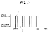
- the laser light 1 is irradiated in pulses in such state to effect sublimation ablation working of the work article 2, and, in the present embodiment, the laser light irradiation is controlled by the open/close control of the mechanical shutter 4-1 to etch the work article 2 in an intermittent sequence.
- the intermittent laser irradiation etching was executed by employing a laser light of a wavelength of 775 nm, a laser pulse oscillation frequency of 1 kHz, a laser irradiation pulse duration of about 150 femtoseconds, an optical energy of about 7 ⁇ joules per pulse concentrated in an area of 20 ⁇ m ⁇ through the photomask 6 and the projection lens 7, namely under a laser irradiating condition with an energy density of 15 terawatt/cm 2 per pulse, on a silicon crystal in the air of normal temperature and normal pressure wherein a cycle of on-state for 0.1 seconds (about 100 laser pulses are irradiated by the train of laser pulses: X) and off-state for 0.5 seconds (the laser pulses are not irradiated: Y) are repeated 5 times by the mechanical shutter 4-1 thereby giving about 500 laser pulses in total to form an etched hole of a depth of about 30 ⁇ m.
- the working according to the present embodiment allows to achieve clean etching without deposit around the worked hole, as shown in Fig. 4.
- the silicon crystal was continuously etched in the air of normal temperature and normal pressure with the total laser irradiation pulses of about 500 pulses under the laser irradiating condition same as above and with the mechanical shutter 4-1 in the on-state (non-shielded state) for 0.5 seconds, the etched hole showed a depth of about 30 ⁇ m, but liquefied silicon was deposited in solid around the worked hole as shown in Fig. 3. The solidified silicon could not be removed easily by mere rinsing with running water.
- the working method of the present embodiment allows to form an extremely clean worked hole without deposit.
- the projected image is focused on the surface of a work article 2 formed of an inorganic material.
- a gas nozzle 4-2 emits nitrogen gas 5-2 in a direction indicated by an arrow whereby a gas flow is generated on the surface of the work article 2.
- the laser light 1 is irradiated in pulses to effect sublimation ablation working of the work article 2.
- the continuous etching was executed, by employing a laser light of a wavelength of 775 nm, a laser pulse oscillation frequency of 1 kHz, a laser irradiation pulse duration of about 150 femtoseconds, an optical energy of about 7 ⁇ joules per pulse concentrated in an area of 20 ⁇ m ⁇ through the photomask 6 and the projection lens 7, namely under a laser irradiating condition with an energy density of 15 terawatt/cm 2 per pulse, on a silicon crystal in the air of normal temperature and normal pressure under an irradiation of 0.5 seconds for giving about 500 laser pulses in total and under a nitrogen gas blow of about 1 m/sec to form an etched hole of a depth of about 30 ⁇ m.
- the working method of the present embodiment under nitrogen gas blowing to the silicon crystal allows to achieve clean etching without deposit around the worked hole, as shown in Fig. 4.
- the silicon crystal was etched in the air atmosphere without the gas blowing shows liquefied silicon deposited in solid around the worked hole as shown in Fig. 3.
- the solidified silicon could not be removed easily by mere rinsing with running water.
- the working method of the present embodiment allows to form an extremely clean worked hole without deposit.
- the optimum rate of the gas flow is considered variable according to the size of the working area and the working speed depending on the laser irradiation energy.
- the projected image is focused on the surface of a work article 2 formed of an inorganic material.
- the work article 2 is closed in a chamber 3 and a window 4-3 closing the chamber 3 and the space around the work article 2 is filled with a work article atmosphere material 5-3.
- the laser light 1 is irradiated in pulses to execute sublimation ablation etching of the work article 2.
- the work article 2 was composed of crystalline silicon, and the chamber 3 was filled with helium gas of normal pressure as the work article atmosphere material 5-3.
- the continuous etching was executed, by employing a laser light of a wavelength of 775 nm, a laser pulse oscillation frequency of 1 kHz, a laser irradiation pulse duration of about 150 femtoseconds, an optical energy of about 7 ⁇ joules per pulse concentrated in an area of 20 ⁇ m ⁇ through the photomask 6 and the projection lens 7, namely under a laser irradiating condition with an energy density of 15 terawatt/cm 2 per pulse, on a silicon crystal under an irradiation for 0.5 seconds for giving about 500 laser pulses in total to form an etched hole of a depth of about 30 ⁇ m.
- the working method of the present embodiment in case of working crystalline silicon in a helium gas atmosphere, allows to achieve clean etching without deposit around the worked hole, as shown in Fig. 4.
- FIG. 7 for outlining the working method of the present embodiment.
- the projected image is focused on the surface of a work article 2 formed of an inorganic material.
- the work article 2 is heated by a heater 4-4 and the temperature is measured by a thermometer 5-4.
- a constant temperature is maintained by turning on and off the heater 4-4 by an unrepresented temperature controller.
- the laser light 1 is irradiated in pulses in such state to effect sublimation ablation working of the work article 2.
- the continuous laser irradiation etching was executed by employing a laser light of a wavelength of 775 nm, a laser pulse oscillation frequency of 1 kHz, a laser irradiation pulse duration of about 150 femtoseconds, an optical energy of about 7 ⁇ joules per pulse concentrated in an area of 20 ⁇ m ⁇ through the photomask 6 and the projection lens 7, namely under a laser irradiating condition with an energy density of 15 terawatt/cm 2 per pulse, on a silicon crystal constituting the work article 2 in a state where the temperature is maintained at about 250°C with a radiation of 0.5 seconds for giving about 500 laser pulses in total to form an etched hole of a depth of about 30 ⁇ m.
- the working method of the present embodiment allows to form an extremely clean worked hole without deposit.
- the deposit tended to decrease as the temperature of crystalline silicon becomes higher from the normal temperature (23°C), but the deposit remained at a temperature less than 200°C.
- the projected image is focused on the surface of a work article 2 formed of an inorganic material.
- the work article 2 is enclosed by a chamber 3 and a window 4-5 capable of transmitting light, and the space around the work article 2 is filled with reduced pressure air 5-5 of which pressure is reduced to 10 Torr or less by an unrepresented pump.
- the laser light 1 is irradiated in pulses in such state to effect sublimation ablation working of the work article 2.
- the continuous laser irradiation etching was executed by employing a laser light of a wavelength of 775 nm, a laser pulse oscillation frequency of 1 kHz, a laser irradiation pulse duration of about 150 femtoseconds, an optical energy of about 7 ⁇ joules per pulse concentrated in an area of 20 ⁇ m ⁇ through the photomask 6 and the projection lens 7, namely under a laser irradiating condition with an energy density of 15 terawatt/cm 2 per pulse, on a silicon crystal for a period of 0.5 seconds in the air of a pressure of 5 Torr thereby giving about 500 laser pulses in total to form an etched hole of a depth of about 30 ⁇ m.
- the working method of the present embodiment allows to form an extremely clean worked hole without deposit.
- the deposit tended to decrease as the pressure of the atmosphere around the crystalline silicon becomes lower from the normal pressure (760 Torr), but the deposit remained at a pressure exceeding about 10 Torr.
- the present invention provides a laser etching method and a laser etching apparatus capable, in laser etching of a work article formed of an inorganic material, of working without deposition around the etching position, and capable of fine working of a material for a micromachine, an IC or a diode device.
- an etching pause time can be provided after predetermined etching to realize a working sequence in which the etching is re-started after the plasma cloud consisting of atomic or molecular particles is scattered, whereby extremely clean working is made possible without deposit around the etching position, as encountered i the conventional continuous etching operation.
- the atomic or molecular particles emitted by ablation are excluded from the work position by collection with the gas flow and remain less in the vicinity of the etching position, whereby extremely clean working is made possible without deposit around the etching position.
- the atomic or molecular particles emitted by ablation can be made to proceed straight without remaining in the vicinity of the etching position, whereby working can be achieved without deposit around the etching position.
- the atomic or molecular particles emitted by ablation are fetched in water and prevented from re-deposition, whereby working can be achieved without deposit around the etching position.
- the atomic or molecular particles emitted by ablation are fetched in silicone oil and prevented from redeposition, whereby working can be achieved without deposit around the etching position.
- the atomic or molecular particles emitted by ablation require a longer time for cooling and liquefaction by the heat from the heated inorganic material and are liquefied or solidified in a position distant from the inorganic material constituting the work article by cooling from the air during the flight, whereby the solid deposition around the etching position is reduced.
- the atomic or molecular particles emitted by ablation fly in a space of a low pressure with a fewer number of atomic or molecular particles and show a lower probability of collision between the particles, thereby increasing the average flight path and less subjected to the changes in the proceeding direction, whereby the particles tend to proceed straight and remain less in the vicinity of the etching position to achieve extremely clean working without deposit around the etching position.
- the first embodiment (intermittent laser irradiation), the second embodiment (gas flow blowing) and the fourth embodiment (heating of work article), or a combination i of the third embodiment (gaseous atmosphere) and the fourth embodiment (heating of work article), or a combination of the first embodiment (intermittent laser irradiation) and the fifth embodiment (reduced pressure atmosphere).
- the invention provides a laser etching method for optical ablation working by irradiating a work article formed of an inorganic material with a laser light from a laser oscillator capable of emitting in succession light pulses of a large energy density in space and time with a pulse radiation time not exceeding 1 picosecond, wherein, in laser etching of the work article formed of the inorganic material by irradiation thereof with the laser light from the laser oscillator with a predetermined pattern and with a predetermined energy density, there is utilized means for preventing deposition of a work by-product around the etching position.
Abstract
Description
wherein, in laser etching of the work article formed of the inorganic material by irradiation thereof with the laser light from the laser oscillator with a predetermined pattern and with a predetermined energy density, there is utilized means for preventing deposition of a work by-product around the etching position.
means for preventing deposition of a work by-product around the etching position for laser etching by irradiation of the work article formed of the inorganic material.
Claims (35)
- A laser etching method for optical ablation working by irradiating a work article formed by an inorganic material with a laser light from a laser oscillator capable of emitting in succession light pulse of a large energy density in space and time with a pulse radiation time not exceeding 1 picosecond:
wherein, in laser etching of the work article formed by said inorganic material by irradiation thereof with the laser light from said laser oscillator with a predetermined pattern and with a predetermined energy density, there is utilized means for preventing deposition of a work by-product around the etching position. - A laser etching method according to claim 1, wherein said means for preventing deposition of the work by-product around the etching position is adapted, in irradiating said work article with said laser light, for executing intermittent irradiation to said work article with an interval longer than the oscillation frequency of the pulsed laser.
- A laser etching method according to claim 1, wherein said means for preventing deposition of the work by-product around the etching position is adapted, in irradiating said work article with said laser light, for executing irradiation of said light in a state where a gas flow is generated in the work position of said work article.
- A laser etching method according to claim 3, wherein the gas flow in the work position of said work article is an air flow.
- A laser etching method according to claim 3, wherein the gas flow in the work position of said work article is a nitrogen flow.
- A laser etching method according to claim 1, wherein said means for preventing deposition of the work by-product around the etching position is adapted, in irradiating and work article with said laser light, for executing irradiation of said laser light in a state where said work article is positioned in an atmosphere other than air.
- A laser etching method according to claim 6, wherein said atmosphere other than air is gas of which medium has an atomic weight smaller than that of nitrogen molecule.
- A laser etching method according to claim 7, wherein said gas is helium gas.
- A laser etching method according to claim 7, wherein said gas is hydrogen gas.
- A laser etching method according to claim 6, wherein said atmosphere other than air is liquid of which medium transmits the laser light.
- A laser etching method according to claim 10, wherein said liquid transmitting the laser light is water.
- A laser etching method according to claim 10, wherein said liquid transmitting the laser light is silicone oil.
- A laser etching method according to claim 1, wherein said means for preventing deposition of the work by-product around the etching position is adapted, in irradiating said work article with said laser light, for executing irradiation of said laser light in a state where said work article is heated to 200°C or higher.
- A laser etching method according to claim 1, wherein said means for preventing deposition of the work by-product around the etching position is adapted, in irradiating said work article with said laser light, for executing irradiation of said laser light in a state where said work article is provided in a gaseous atmosphere of a pressure not exceeding 10 Torr.
- A laser etching method according to claim 1, wherein said inorganic material is a crystal covalent bond.
- A laser etching method according to claim 1, wherein said inorganic material is crystal or amorphous silicon.
- A laser etching method according to claim 1, wherein said inorganic material is a silicon compound.
- A laser etching method according to claim 1, wherein said laser oscillator has a spatial compression device for light propagation.
- A laser etching method according to claim 18, wherein said spatial compression device for light propagation includes chirping pulse generation means and vertical mode synchronization means utilizing the optical wavelength dispersing characteristics.
- A laser etching apparatus provided with from a laser oscillator capable of emitting in succession light pulses of a large energy density in space and time with a pulse radiation time not exceeding 1 picosecond and adapted for optical ablation working of a work article formed of an inorganic material by irradiation of said work article with a laser light from said laser oscillator with a predetermined pattern and with a predetermined energy density, the apparatus comprising:
means for preventing deposition of a work by-product around the etching position for laser etching by irradiation of said work article formed of the inorganic material. - A laser etching apparatus according to claim 20, wherein said means for preventing deposition of the work by-product around the etching position includes a mechanical shutter for achieving intermittent irradiation with an interval longer than the oscillation frequency of the pulsed laser by controlling the laser light from said laser oscillator by open/close control, thereby working said work article.
- A laser etching apparatus according to claim 20, wherein said means for preventing deposition of the work by-product around the etching position includes means for causing a gas flow in the work position of said work article formed of said inorganic material, and is adapted for working said work article by irradiating said work article with said laser light in a state where a gas flow is caused in the work position of said work article formed of the inorganic material.
- A laser etching apparatus according to claim 22, wherein said means for causing the gas flow in the work position of said work article is adapted to cause an air flow.
- A laser etching apparatus according to claim 22, wherein said means for causing the gas flow in the work position of said work article is adapted to cause a nitrogen flow.
- A laser etching apparatus according to claim 20, wherein said means for preventing deposition of the work by-product around the etching position includes a chamber and a light transmitting member capable of closing said chamber, and is adapted to work said work article formed of the inorganic material by positioning said work article in said chamber filled with a medium other than air and closed by said light transmitting member, and irradiating said work article with said laser light through said light transmitting member.
- A laser etching apparatus according to claim 25, wherein said medium filled in said chamber other than air is gas of an atomic weight smaller than that of nitrogen molecule.
- A laser etching apparatus according to claim 26, wherein said gas is helium gas.
- A laser etching apparatus according to claim 26, wherein said gas is hydrogen gas.
- A laser etching apparatus according to claim 25, wherein said medium filled in said chamber other than air is liquid capable of transmitting said laser light.
- A laser etching apparatus according to claim 29, wherein said liquid transmitting said laser light is water.
- A laser etching apparatus according to claim 29, wherein said liquid transmitting said laser light is silicone oil.
- A laser etching apparatus according to claim 20, wherein said means for preventing deposition of the work by-product around the etching position includes a heater to be controlled at a predetermined temperature by temperature adjusting means and is adapted for working said work article by maintaining said work article formed of the inorganic material at the predetermined temperature and irradiating said work article with said laser light.
- A laser etching apparatus according to claim 20, wherein said means for preventing deposition of the work by-product around the etching position includes a chamber and a light transmitting member capable of closing said chamber, and is adapted for working said work article formed of the inorganic material by irradiation with said laser light, by positioning said work article in said chamber evacuated to a pressure not exceeding 10 Torr and closed by said light transmitting member and irradiating said work article with said laser light through said light transmitting member.
- A laser etching apparatus according to claim 20, wherein said laser oscillator has a spatial compression device for light propagation.
- A laser etching apparatus according to claim 34, wherein said spatial compression device for light propagation includes chirping pulse generation means and vertical mode synchronization means utilizing the optical wavelength dispersing characteristics.
Applications Claiming Priority (10)
| Application Number | Priority Date | Filing Date | Title |
|---|---|---|---|
| JP33955899 | 1999-11-30 | ||
| JP33955699 | 1999-11-30 | ||
| JP33955799 | 1999-11-30 | ||
| JP33956099 | 1999-11-30 | ||
| JP33955699 | 1999-11-30 | ||
| JP33955999 | 1999-11-30 | ||
| JP33955999 | 1999-11-30 | ||
| JP33956099 | 1999-11-30 | ||
| JP33955799 | 1999-11-30 | ||
| JP33955899 | 1999-11-30 |
Publications (3)
| Publication Number | Publication Date |
|---|---|
| EP1106299A2 true EP1106299A2 (en) | 2001-06-13 |
| EP1106299A3 EP1106299A3 (en) | 2002-11-13 |
| EP1106299B1 EP1106299B1 (en) | 2007-01-10 |
Family
ID=27531251
Family Applications (1)
| Application Number | Title | Priority Date | Filing Date |
|---|---|---|---|
| EP00126121A Expired - Lifetime EP1106299B1 (en) | 1999-11-30 | 2000-11-29 | Laser etching method |
Country Status (10)
| Country | Link |
|---|---|
| US (3) | US6861364B1 (en) |
| EP (1) | EP1106299B1 (en) |
| KR (1) | KR100451623B1 (en) |
| BR (1) | BR0005673A (en) |
| CA (1) | CA2326881A1 (en) |
| DE (1) | DE60032862T2 (en) |
| HK (1) | HK1037565A1 (en) |
| MX (1) | MXPA00011780A (en) |
| SG (1) | SG86451A1 (en) |
| TW (1) | TW553848B (en) |
Families Citing this family (22)
| Publication number | Priority date | Publication date | Assignee | Title |
|---|---|---|---|---|
| SG86451A1 (en) * | 1999-11-30 | 2002-02-19 | Canon Kk | Laser etching method and apparatus therefor |
| US20060078847A1 (en) * | 2000-09-29 | 2006-04-13 | Kwan Norman H | Dental implant system and additional methods of attachment |
| US7583710B2 (en) * | 2001-01-30 | 2009-09-01 | Board Of Trustees Operating Michigan State University | Laser and environmental monitoring system |
| US7973936B2 (en) * | 2001-01-30 | 2011-07-05 | Board Of Trustees Of Michigan State University | Control system and apparatus for use with ultra-fast laser |
| US7450618B2 (en) * | 2001-01-30 | 2008-11-11 | Board Of Trustees Operating Michigan State University | Laser system using ultrashort laser pulses |
| US8208505B2 (en) * | 2001-01-30 | 2012-06-26 | Board Of Trustees Of Michigan State University | Laser system employing harmonic generation |
| US7567596B2 (en) * | 2001-01-30 | 2009-07-28 | Board Of Trustees Of Michigan State University | Control system and apparatus for use with ultra-fast laser |
| RU2226183C2 (en) * | 2002-02-21 | 2004-03-27 | Алексеев Андрей Михайлович | Method for cutting of transparent non-metal materials |
| US7390704B2 (en) * | 2004-06-16 | 2008-06-24 | Semiconductor Energy Laboratory Co., Ltd. | Laser process apparatus, laser irradiation method, and method for manufacturing semiconductor device |
| US8633437B2 (en) | 2005-02-14 | 2014-01-21 | Board Of Trustees Of Michigan State University | Ultra-fast laser system |
| US8803028B1 (en) | 2005-04-13 | 2014-08-12 | Genlyte Thomas Group, Llc | Apparatus for etching multiple surfaces of luminaire reflector |
| WO2007064703A2 (en) * | 2005-11-30 | 2007-06-07 | Board Of Trustees Of Michigan State University | Laser based identification of molecular characteristics |
| US8846551B2 (en) | 2005-12-21 | 2014-09-30 | University Of Virginia Patent Foundation | Systems and methods of laser texturing of material surfaces and their applications |
| WO2007145702A2 (en) * | 2006-04-10 | 2007-12-21 | Board Of Trustees Of Michigan State University | Laser material processing systems and methods with, in particular, use of a hollow waveguide for broadening the bandwidth of the pulse above 20 nm |
| US20090207869A1 (en) * | 2006-07-20 | 2009-08-20 | Board Of Trustees Of Michigan State University | Laser plasmonic system |
| EP2232653B1 (en) | 2007-12-21 | 2013-03-27 | Board of Trustees of Michigan State University | Phase control in ultrashort pulse lasers by a deformable mirror in the pulse stretcher |
| US8675699B2 (en) * | 2009-01-23 | 2014-03-18 | Board Of Trustees Of Michigan State University | Laser pulse synthesis system |
| DE102009007630A1 (en) * | 2009-02-05 | 2010-08-12 | Basf Coatings Ag | Coating agent for corrosion-resistant coatings |
| WO2010141128A2 (en) | 2009-03-05 | 2010-12-09 | Board Of Trustees Of Michigan State University | Laser amplification system |
| US8630322B2 (en) * | 2010-03-01 | 2014-01-14 | Board Of Trustees Of Michigan State University | Laser system for output manipulation |
| US10131086B2 (en) | 2011-06-30 | 2018-11-20 | University Of Virginia Patent Foundation | Micro-structure and nano-structure replication methods and article of manufacture |
| US10300557B2 (en) * | 2016-09-23 | 2019-05-28 | Apple Inc. | Hybrid substrate processing |
Citations (5)
| Publication number | Priority date | Publication date | Assignee | Title |
|---|---|---|---|---|
| US5601737A (en) * | 1993-07-27 | 1997-02-11 | Matsushita Electric Works, Ltd. | Surface treating process involving energy beam irradiation onto multilayered conductor parts of printed circuit board |
| WO1997024768A1 (en) * | 1995-12-29 | 1997-07-10 | Pacific Solar Pty. Limited | Improved laser grooving and doping method |
| US5720894A (en) * | 1996-01-11 | 1998-02-24 | The Regents Of The University Of California | Ultrashort pulse high repetition rate laser system for biological tissue processing |
| WO1998010494A1 (en) * | 1996-09-06 | 1998-03-12 | Andreas Stingl | Short-pulse laser device |
| EP0927595A1 (en) * | 1996-08-12 | 1999-07-07 | Armco Inc. | Descaling metal with a laser having a very short pulse width and high average power |
Family Cites Families (28)
| Publication number | Priority date | Publication date | Assignee | Title |
|---|---|---|---|---|
| US4292093A (en) * | 1979-12-28 | 1981-09-29 | The United States Of America As Represented By The United States Department Of Energy | Method using laser irradiation for the production of atomically clean crystalline silicon and germanium surfaces |
| JPS5973189A (en) | 1982-10-18 | 1984-04-25 | Sumitomo Metal Ind Ltd | Surface scarfing method |
| US4739385A (en) * | 1982-10-21 | 1988-04-19 | American Telephone And Telegraph Company, At&T Bell Laboratories | Modulation-doped photodetector |
| JPS59182529A (en) | 1983-04-01 | 1984-10-17 | Hitachi Ltd | Pattern formation of semiconductor layer |
| US4764930A (en) * | 1988-01-27 | 1988-08-16 | Intelligent Surgical Lasers | Multiwavelength laser source |
| US5024968A (en) * | 1988-07-08 | 1991-06-18 | Engelsberg Audrey C | Removal of surface contaminants by irradiation from a high-energy source |
| US5196376A (en) | 1991-03-01 | 1993-03-23 | Polycon Corporation | Laser lithography for integrated circuit and integrated circuit interconnect manufacture |
| US5362941A (en) * | 1992-06-11 | 1994-11-08 | Iomega Corporation | Exhaust and particle wastes collecting device for laser etching |
| US5359176A (en) | 1993-04-02 | 1994-10-25 | International Business Machines Corporation | Optics and environmental protection device for laser processing applications |
| US5814156A (en) * | 1993-09-08 | 1998-09-29 | Uvtech Systems Inc. | Photoreactive surface cleaning |
| JP3279789B2 (en) * | 1993-12-10 | 2002-04-30 | 株式会社小松製作所 | Colored laser marking device |
| US6016324A (en) * | 1994-08-24 | 2000-01-18 | Jmar Research, Inc. | Short pulse laser system |
| US6388366B1 (en) * | 1995-05-08 | 2002-05-14 | Wayne State University | Carbon nitride cold cathode |
| US6373026B1 (en) * | 1996-07-31 | 2002-04-16 | Mitsubishi Denki Kabushiki Kaisha | Laser beam machining method for wiring board, laser beam machining apparatus for wiring board, and carbonic acid gas laser oscillator for machining wiring board |
| JPH09107168A (en) * | 1995-08-07 | 1997-04-22 | Mitsubishi Electric Corp | Laser processing method of wiring board, laser processing device of wiring board and carbon dioxide gas laser oscillator for wiring board processing |
| US5950071A (en) * | 1995-11-17 | 1999-09-07 | Lightforce Technology, Inc. | Detachment and removal of microscopic surface contaminants using a pulsed detach light |
| US5747120A (en) * | 1996-03-29 | 1998-05-05 | Regents Of The University Of California | Laser ablated hard coating for microtools |
| US6165649A (en) * | 1997-01-21 | 2000-12-26 | International Business Machines Corporation | Methods for repair of photomasks |
| US6156030A (en) | 1997-06-04 | 2000-12-05 | Y-Beam Technologies, Inc. | Method and apparatus for high precision variable rate material removal and modification |
| JPH11123577A (en) * | 1997-10-21 | 1999-05-11 | Nippon Sheet Glass Co Ltd | Laser machining method for brittle material |
| JP3401425B2 (en) * | 1998-01-21 | 2003-04-28 | 理化学研究所 | Laser processing method and laser processing apparatus |
| US6533822B2 (en) | 1998-01-30 | 2003-03-18 | Xerox Corporation | Creating summaries along with indicators, and automatically positioned tabs |
| JPH11254174A (en) | 1998-03-13 | 1999-09-21 | Seiko Epson Corp | Method, container and device for laser beam machining |
| US6333485B1 (en) * | 1998-12-11 | 2001-12-25 | International Business Machines Corporation | Method for minimizing sample damage during the ablation of material using a focused ultrashort pulsed beam |
| JP3945951B2 (en) * | 1999-01-14 | 2007-07-18 | 日立ビアメカニクス株式会社 | Laser processing method and laser processing machine |
| US6760973B1 (en) * | 1999-06-30 | 2004-07-13 | Canon Kabushiki Kaisha | Laser working method and method for producing ink jet recording head |
| SG86451A1 (en) * | 1999-11-30 | 2002-02-19 | Canon Kk | Laser etching method and apparatus therefor |
| US6582857B1 (en) * | 2000-03-16 | 2003-06-24 | International Business Machines Corporation | Repair of masks to promote adhesion of patches |
-
2000
- 2000-11-22 SG SG200006804A patent/SG86451A1/en unknown
- 2000-11-22 US US09/717,242 patent/US6861364B1/en not_active Expired - Fee Related
- 2000-11-23 TW TW089124940A patent/TW553848B/en not_active IP Right Cessation
- 2000-11-24 CA CA002326881A patent/CA2326881A1/en not_active Abandoned
- 2000-11-29 MX MXPA00011780A patent/MXPA00011780A/en unknown
- 2000-11-29 DE DE60032862T patent/DE60032862T2/en not_active Expired - Lifetime
- 2000-11-29 EP EP00126121A patent/EP1106299B1/en not_active Expired - Lifetime
- 2000-11-30 KR KR10-2000-0071797A patent/KR100451623B1/en not_active IP Right Cessation
- 2000-11-30 BR BR0005673-1A patent/BR0005673A/en not_active IP Right Cessation
-
2001
- 2001-11-22 HK HK01108252A patent/HK1037565A1/en not_active IP Right Cessation
-
2004
- 2004-09-17 US US10/943,026 patent/US7169709B2/en not_active Expired - Fee Related
-
2007
- 2007-01-03 US US11/619,408 patent/US7674395B2/en not_active Expired - Fee Related
Patent Citations (5)
| Publication number | Priority date | Publication date | Assignee | Title |
|---|---|---|---|---|
| US5601737A (en) * | 1993-07-27 | 1997-02-11 | Matsushita Electric Works, Ltd. | Surface treating process involving energy beam irradiation onto multilayered conductor parts of printed circuit board |
| WO1997024768A1 (en) * | 1995-12-29 | 1997-07-10 | Pacific Solar Pty. Limited | Improved laser grooving and doping method |
| US5720894A (en) * | 1996-01-11 | 1998-02-24 | The Regents Of The University Of California | Ultrashort pulse high repetition rate laser system for biological tissue processing |
| EP0927595A1 (en) * | 1996-08-12 | 1999-07-07 | Armco Inc. | Descaling metal with a laser having a very short pulse width and high average power |
| WO1998010494A1 (en) * | 1996-09-06 | 1998-03-12 | Andreas Stingl | Short-pulse laser device |
Non-Patent Citations (2)
| Title |
|---|
| PATENT ABSTRACTS OF JAPAN vol. 008, no. 180 (M-318), 18 August 1984 (1984-08-18) & JP 59 073189 A (SUMITOMO METAL IND LTD), 25 April 1984 (1984-04-25) * |
| PATENT ABSTRACTS OF JAPAN vol. 1999, no. 14, 22 December 1999 (1999-12-22) & JP 11 254174 A (SEIKO EPSON CORP), 21 September 1999 (1999-09-21) * |
Also Published As
| Publication number | Publication date |
|---|---|
| HK1037565A1 (en) | 2002-02-15 |
| BR0005673A (en) | 2001-07-31 |
| CA2326881A1 (en) | 2001-05-30 |
| TW553848B (en) | 2003-09-21 |
| SG86451A1 (en) | 2002-02-19 |
| US7169709B2 (en) | 2007-01-30 |
| DE60032862D1 (en) | 2007-02-22 |
| EP1106299A3 (en) | 2002-11-13 |
| DE60032862T2 (en) | 2007-10-25 |
| KR100451623B1 (en) | 2004-10-08 |
| US20050032380A1 (en) | 2005-02-10 |
| KR20010052036A (en) | 2001-06-25 |
| MXPA00011780A (en) | 2002-06-04 |
| US6861364B1 (en) | 2005-03-01 |
| US7674395B2 (en) | 2010-03-09 |
| EP1106299B1 (en) | 2007-01-10 |
| US20070125746A1 (en) | 2007-06-07 |
Similar Documents
| Publication | Publication Date | Title |
|---|---|---|
| US7674395B2 (en) | Laser etching method and apparatus therefor | |
| US5057184A (en) | Laser etching of materials in liquids | |
| SE510133C2 (en) | Laser plasma X-ray source utilizing fluids as radiation target | |
| US6529228B1 (en) | Laser working method, method for producing ink jet recording utilizing the same, and ink jet recording method produced by such method | |
| JP2003047923A (en) | Laser cleaning apparatus and method | |
| JP2001219290A (en) | Method and apparatus for laser beam etching | |
| US20010050312A1 (en) | Laser processing method and laser processing apparatus | |
| JP3932930B2 (en) | Laser processing apparatus and laser processing method | |
| US6938341B2 (en) | Method for manufacturing an ink discharge port of an ink jet recording head | |
| US6747244B1 (en) | Laser working apparatus, laser working method, method for producing ink jet recording head utilizing such laser working apparatus or method, and ink jet recording head formed by such producing method | |
| JP2001232487A (en) | Laser beam machining device and method, manufacturing method for ink jet recording head using the device or the method and ink jet recording head manufactured by the manufacturing method | |
| AU7183800A (en) | Laser etching method and apparatus therefor | |
| JPS595621A (en) | Forming method for thin-film | |
| RU2764237C1 (en) | Method and device for cleaning substrate and computer software product | |
| JP2003053579A (en) | Device and method for laser beam machining | |
| CN1297799A (en) | Laser corrosion method and its apparatus | |
| KR100589673B1 (en) | Washing Methods based on pulse laser-induced shock wave and evaporation of liquid film and Apparatus thereof | |
| JP2001219282A (en) | Laser beam machining method, manufacturing method of ink jet recording head using laser beam machining method, ink jet recording head manufactured by manufacturing method | |
| JP2004160478A (en) | Method and apparatus for laser beam machining | |
| US20010035400A1 (en) | Method for sundering semiconductor materials | |
| JPH09256141A (en) | Formation of thin film and device therefor | |
| JP2924861B2 (en) | Semiconductor wafer laser marking apparatus and method | |
| Kaplan | Precision ablation processing | |
| Jeong | Laser Technology in micro manufacturing | |
| KR20190123855A (en) | Method for manufacturing multi-scale silicon pattern and device manufactured by the same |
Legal Events
| Date | Code | Title | Description |
|---|---|---|---|
| PUAI | Public reference made under article 153(3) epc to a published international application that has entered the european phase |
Free format text: ORIGINAL CODE: 0009012 |
|
| AK | Designated contracting states |
Kind code of ref document: A2 Designated state(s): AT BE CH CY DE DK ES FI FR GB GR IE IT LI LU MC NL PT SE TR |
|
| AX | Request for extension of the european patent |
Free format text: AL;LT;LV;MK;RO;SI |
|
| PUAL | Search report despatched |
Free format text: ORIGINAL CODE: 0009013 |
|
| RIC1 | Information provided on ipc code assigned before grant |
Free format text: 7B 23K 26/16 A, 7B 23K 26/12 B, 7B 23K 26/14 B, 7B 44C 1/22 B, 7G 03F 7/00 B, 7H 01L 21/302 B |
|
| AK | Designated contracting states |
Kind code of ref document: A3 Designated state(s): AT BE CH CY DE DK ES FI FR GB GR IE IT LI LU MC NL PT SE TR |
|
| AX | Request for extension of the european patent |
Free format text: AL;LT;LV;MK;RO;SI |
|
| 17P | Request for examination filed |
Effective date: 20030327 |
|
| AKX | Designation fees paid |
Designated state(s): AT BE CH CY DE DK ES FI FR GB GR IE IT LI LU MC NL PT SE TR |
|
| 17Q | First examination report despatched |
Effective date: 20030915 |
|
| RTI1 | Title (correction) |
Free format text: LASER ETCHING METHOD |
|
| GRAP | Despatch of communication of intention to grant a patent |
Free format text: ORIGINAL CODE: EPIDOSNIGR1 |
|
| GRAS | Grant fee paid |
Free format text: ORIGINAL CODE: EPIDOSNIGR3 |
|
| GRAA | (expected) grant |
Free format text: ORIGINAL CODE: 0009210 |
|
| AK | Designated contracting states |
Kind code of ref document: B1 Designated state(s): AT BE CH CY DE DK ES FI FR GB GR IE IT LI LU MC NL PT SE TR |
|
| PG25 | Lapsed in a contracting state [announced via postgrant information from national office to epo] |
Ref country code: DK Free format text: LAPSE BECAUSE OF FAILURE TO SUBMIT A TRANSLATION OF THE DESCRIPTION OR TO PAY THE FEE WITHIN THE PRESCRIBED TIME-LIMIT Effective date: 20070110 Ref country code: LI Free format text: LAPSE BECAUSE OF FAILURE TO SUBMIT A TRANSLATION OF THE DESCRIPTION OR TO PAY THE FEE WITHIN THE PRESCRIBED TIME-LIMIT Effective date: 20070110 Ref country code: NL Free format text: LAPSE BECAUSE OF FAILURE TO SUBMIT A TRANSLATION OF THE DESCRIPTION OR TO PAY THE FEE WITHIN THE PRESCRIBED TIME-LIMIT Effective date: 20070110 Ref country code: FI Free format text: LAPSE BECAUSE OF FAILURE TO SUBMIT A TRANSLATION OF THE DESCRIPTION OR TO PAY THE FEE WITHIN THE PRESCRIBED TIME-LIMIT Effective date: 20070110 Ref country code: CH Free format text: LAPSE BECAUSE OF FAILURE TO SUBMIT A TRANSLATION OF THE DESCRIPTION OR TO PAY THE FEE WITHIN THE PRESCRIBED TIME-LIMIT Effective date: 20070110 Ref country code: AT Free format text: LAPSE BECAUSE OF FAILURE TO SUBMIT A TRANSLATION OF THE DESCRIPTION OR TO PAY THE FEE WITHIN THE PRESCRIBED TIME-LIMIT Effective date: 20070110 |
|
| REG | Reference to a national code |
Ref country code: GB Ref legal event code: FG4D |
|
| REG | Reference to a national code |
Ref country code: IE Ref legal event code: FG4D |
|
| REF | Corresponds to: |
Ref document number: 60032862 Country of ref document: DE Date of ref document: 20070222 Kind code of ref document: P |
|
| REG | Reference to a national code |
Ref country code: HK Ref legal event code: GR Ref document number: 1037565 Country of ref document: HK |
|
| PG25 | Lapsed in a contracting state [announced via postgrant information from national office to epo] |
Ref country code: SE Free format text: LAPSE BECAUSE OF FAILURE TO SUBMIT A TRANSLATION OF THE DESCRIPTION OR TO PAY THE FEE WITHIN THE PRESCRIBED TIME-LIMIT Effective date: 20070410 |
|
| PG25 | Lapsed in a contracting state [announced via postgrant information from national office to epo] |
Ref country code: ES Free format text: LAPSE BECAUSE OF FAILURE TO SUBMIT A TRANSLATION OF THE DESCRIPTION OR TO PAY THE FEE WITHIN THE PRESCRIBED TIME-LIMIT Effective date: 20070421 |
|
| PG25 | Lapsed in a contracting state [announced via postgrant information from national office to epo] |
Ref country code: PT Free format text: LAPSE BECAUSE OF FAILURE TO SUBMIT A TRANSLATION OF THE DESCRIPTION OR TO PAY THE FEE WITHIN THE PRESCRIBED TIME-LIMIT Effective date: 20070611 |
|
| NLV1 | Nl: lapsed or annulled due to failure to fulfill the requirements of art. 29p and 29m of the patents act | ||
| ET | Fr: translation filed | ||
| REG | Reference to a national code |
Ref country code: CH Ref legal event code: PL |
|
| PLBE | No opposition filed within time limit |
Free format text: ORIGINAL CODE: 0009261 |
|
| STAA | Information on the status of an ep patent application or granted ep patent |
Free format text: STATUS: NO OPPOSITION FILED WITHIN TIME LIMIT |
|
| 26N | No opposition filed |
Effective date: 20071011 |
|
| PG25 | Lapsed in a contracting state [announced via postgrant information from national office to epo] |
Ref country code: BE Free format text: LAPSE BECAUSE OF FAILURE TO SUBMIT A TRANSLATION OF THE DESCRIPTION OR TO PAY THE FEE WITHIN THE PRESCRIBED TIME-LIMIT Effective date: 20070110 |
|
| PG25 | Lapsed in a contracting state [announced via postgrant information from national office to epo] |
Ref country code: GR Free format text: LAPSE BECAUSE OF FAILURE TO SUBMIT A TRANSLATION OF THE DESCRIPTION OR TO PAY THE FEE WITHIN THE PRESCRIBED TIME-LIMIT Effective date: 20070411 |
|
| PG25 | Lapsed in a contracting state [announced via postgrant information from national office to epo] |
Ref country code: MC Free format text: LAPSE BECAUSE OF NON-PAYMENT OF DUE FEES Effective date: 20071130 |
|
| PG25 | Lapsed in a contracting state [announced via postgrant information from national office to epo] |
Ref country code: IE Free format text: LAPSE BECAUSE OF NON-PAYMENT OF DUE FEES Effective date: 20071129 |
|
| PG25 | Lapsed in a contracting state [announced via postgrant information from national office to epo] |
Ref country code: CY Free format text: LAPSE BECAUSE OF FAILURE TO SUBMIT A TRANSLATION OF THE DESCRIPTION OR TO PAY THE FEE WITHIN THE PRESCRIBED TIME-LIMIT Effective date: 20070110 |
|
| PG25 | Lapsed in a contracting state [announced via postgrant information from national office to epo] |
Ref country code: LU Free format text: LAPSE BECAUSE OF NON-PAYMENT OF DUE FEES Effective date: 20071129 |
|
| PG25 | Lapsed in a contracting state [announced via postgrant information from national office to epo] |
Ref country code: TR Free format text: LAPSE BECAUSE OF FAILURE TO SUBMIT A TRANSLATION OF THE DESCRIPTION OR TO PAY THE FEE WITHIN THE PRESCRIBED TIME-LIMIT Effective date: 20070110 |
|
| PGFP | Annual fee paid to national office [announced via postgrant information from national office to epo] |
Ref country code: DE Payment date: 20101130 Year of fee payment: 11 |
|
| PGFP | Annual fee paid to national office [announced via postgrant information from national office to epo] |
Ref country code: GB Payment date: 20101126 Year of fee payment: 11 Ref country code: IT Payment date: 20101112 Year of fee payment: 11 |
|
| PGFP | Annual fee paid to national office [announced via postgrant information from national office to epo] |
Ref country code: FR Payment date: 20111212 Year of fee payment: 12 |
|
| GBPC | Gb: european patent ceased through non-payment of renewal fee |
Effective date: 20121129 |
|
| REG | Reference to a national code |
Ref country code: FR Ref legal event code: ST Effective date: 20130731 |
|
| PG25 | Lapsed in a contracting state [announced via postgrant information from national office to epo] |
Ref country code: IT Free format text: LAPSE BECAUSE OF NON-PAYMENT OF DUE FEES Effective date: 20121129 |
|
| REG | Reference to a national code |
Ref country code: DE Ref legal event code: R119 Ref document number: 60032862 Country of ref document: DE Effective date: 20130601 |
|
| PG25 | Lapsed in a contracting state [announced via postgrant information from national office to epo] |
Ref country code: DE Free format text: LAPSE BECAUSE OF NON-PAYMENT OF DUE FEES Effective date: 20130601 |
|
| PG25 | Lapsed in a contracting state [announced via postgrant information from national office to epo] |
Ref country code: FR Free format text: LAPSE BECAUSE OF NON-PAYMENT OF DUE FEES Effective date: 20121130 Ref country code: GB Free format text: LAPSE BECAUSE OF NON-PAYMENT OF DUE FEES Effective date: 20121129 |