EP1107060A1 - Photofinishing method and apparatus - Google Patents
Photofinishing method and apparatus Download PDFInfo
- Publication number
- EP1107060A1 EP1107060A1 EP00204078A EP00204078A EP1107060A1 EP 1107060 A1 EP1107060 A1 EP 1107060A1 EP 00204078 A EP00204078 A EP 00204078A EP 00204078 A EP00204078 A EP 00204078A EP 1107060 A1 EP1107060 A1 EP 1107060A1
- Authority
- EP
- European Patent Office
- Prior art keywords
- film
- photosensitive media
- exposed portion
- processing
- photosensitive
- Prior art date
- Legal status (The legal status is an assumption and is not a legal conclusion. Google has not performed a legal analysis and makes no representation as to the accuracy of the status listed.)
- Withdrawn
Links
Images


Classifications
-
- G—PHYSICS
- G03—PHOTOGRAPHY; CINEMATOGRAPHY; ANALOGOUS TECHNIQUES USING WAVES OTHER THAN OPTICAL WAVES; ELECTROGRAPHY; HOLOGRAPHY
- G03D—APPARATUS FOR PROCESSING EXPOSED PHOTOGRAPHIC MATERIALS; ACCESSORIES THEREFOR
- G03D5/00—Liquid processing apparatus in which no immersion is effected; Washing apparatus in which no immersion is effected
-
- G—PHYSICS
- G03—PHOTOGRAPHY; CINEMATOGRAPHY; ANALOGOUS TECHNIQUES USING WAVES OTHER THAN OPTICAL WAVES; ELECTROGRAPHY; HOLOGRAPHY
- G03B—APPARATUS OR ARRANGEMENTS FOR TAKING PHOTOGRAPHS OR FOR PROJECTING OR VIEWING THEM; APPARATUS OR ARRANGEMENTS EMPLOYING ANALOGOUS TECHNIQUES USING WAVES OTHER THAN OPTICAL WAVES; ACCESSORIES THEREFOR
- G03B27/00—Photographic printing apparatus
- G03B27/32—Projection printing apparatus, e.g. enlarger, copying camera
-
- G—PHYSICS
- G03—PHOTOGRAPHY; CINEMATOGRAPHY; ANALOGOUS TECHNIQUES USING WAVES OTHER THAN OPTICAL WAVES; ELECTROGRAPHY; HOLOGRAPHY
- G03D—APPARATUS FOR PROCESSING EXPOSED PHOTOGRAPHIC MATERIALS; ACCESSORIES THEREFOR
- G03D5/00—Liquid processing apparatus in which no immersion is effected; Washing apparatus in which no immersion is effected
- G03D5/04—Liquid processing apparatus in which no immersion is effected; Washing apparatus in which no immersion is effected using liquid sprays
Definitions
- the present invention relates to photofinishing of photosensitive material, and more particularly, to a method and apparatus for photofinishing a photosensitive material using an apparently dry development process.
- Typical photofinishing of photosensitive media comprises the development of the photosensitive media using wet processing system followed by printing of the image onto a second photosensitive media, which is also processed using a conventional wet process system.
- Conventional wet process comprises the passing of the film through a plurality of processing tanks, each tank containing a processed solution.
- Such conventional wet processing is relatively time-consuming, restricted to specific types of films, must be carefully monitored and maintained in order to ensure consistent high quality, special care must be taken in the using and disposal of the processing solutions.
- Bi-Mat development system whereby 35mm instant color slide film is developed.
- An example of such a system is the PolaChrome CS 35mm instant color slide film, which incorporates a black and white emulsion layer provided on a substrate and an additive color screen which is used to produce color images.
- a donor strip is coated with a processing solution, which is then caused to come in contact with the exposed film through use of a pair of laminating rollers. Since the emulsion is a black and white emulsion, only a single processing solution is applied.
- a problem with this system is that it sacrifices film speed, D-min density, an image quality in order to obtain visually acceptable slide image.
- U.S. Patent 5,627,016 discloses a system similar to the Bi-Mat system, which is relatively simple and low cost. While the system disclosed therein provides an improvement over the PolaChrome CS 35mm system, it is not suitable for use with film having substantially different chemistry and is not designed for doing partial roll developing and printing.
- the present invention provides a method and apparatus for photofinishing a variety of different type photosensitive materials using a single, simple low-cost device. Additionally, the system allows for partial roll development and allows the providing of a large variety of different custom image products to be produced.
- an apparatus for developing a strip of photosensitive media having image exposure area having an undeveloped exposed portion thereon comprising:
- an apparatus for developing a strip photosensitive media having image exposure area having an undeveloped exposed portion thereon comprising:
- a method for developing a strip of photosensitive media provided in a film cartridge comprising the steps of:
- a method for developing a strip photosensitive media having image exposure area having an undeveloped exposed portion thereon comprising the steps of:
- a photofinishing apparatus 10 made in accordance with the present invention.
- apparatus 10 is a customer self service kiosk which does not require retail sale persons or an operator.
- the apparatus 10 includes a development section 12, as shown separately by Figs. 2-5, for developing exposed images on a photosensitive media.
- the development section 12 is designed to be a Bi-Mat development system.
- a Bi-Mat type development system shall be considered a system which utilizes a single processing solution to fully develop the photosensitive emulsion layer on a supporting substrata.
- the photofinishing apparatus 10 is designed to process photographic film 13 having a front side 14 and a back side 15 with a photosensitive emulsion layer on the front 14.
- the apparatus 10 includes a holding mechanism 16 for holding a film cartridge 18, which is designed to hold photographic film 13.
- the film cartridge 18 is of the thrust film type, such as illustrated in U.S. Patent Nos. 5,200,777 and 5,031,852 which incorporates the references in their entirety. In such thrust film cartridges, the film can be automatically thrust out of or back into the film cartridge 18.
- the photographic film 13 is helically wound about a film core (not shown), which is rotatably mounted to the cartridge 18.
- a light valve (also not shown) is rotatably mounted to cartridge 18 adjacent an opening in cartridge 18.
- film 13 When the light valve is in the open position film 13 may to be either thrust out, or thrust back into the cartridge 18 by rotation of the core in the appropriate direction.
- a transport mechanism is provided for moving film 13 along a film processing path 34.
- the transport mechanism for moving the film motor (not shown) provided in apparatus 10 engages and rotates the core of the cartridge.
- the holding mechanism includes an opening 20 having an inner configuration designed to mate with the outer configuration of the film cartridge 18.
- the opening 20 is oriented in a direction substantially perpendicular to processing path 34. This allows the end of the core of cartridge 18 to easily engage the motor used to rotate the core. Once properly engaged in the opening 20, film 13 can be thrust out of, or into cartridge 18 as appropriate.
- a sensor 19 is provided for reading the film DX code on cartridge 18.
- the DX code contains information that can be used by apparatus 10 for determining if the film 13 contained therein is suitable for processing by apparatus 10 and for selecting the appropriate algorithm for processing of the scanned image data as discussed later herein.
- Development section 12 includes a supply reel 22 having a donor web 24 wound around a core 25.
- the donor web 24 is unwound from supply reel 22 through a film processing section 26 by a motor (not shown) which drives the core 27 of a take-up reel 28.
- a pair of guide rollers 30 provides for guiding donor web 24 through the processing section 26.
- a backer member 32 is provided between guide rollers 30 for providing a supporting surface for donor web 24, as discussed later herein.
- APS advanced photosystem
- a magnetic read/write head 38 Disposed adjacent the cartridge 18 along the processing film path 34 there is provided a magnetic read/write head 38 for reading any information contained magnetically on the film and/or for writing magnetic information thereon.
- An infrared sensor 39 is provided adjacent read/write head 38. Infrared sensors can see through unprocessed film without exposing it. Processed film and unprocessed film provide different "IR" signatures.
- a digital scanner 40 preferably of a high resolution, is provided for scanning images developed on film 13.
- the scanner 40 in the embodiment illustrated, is a linear CCD array (charge coupled device), which can scan the images and thereby produce a digital record of the images scanned. It is to be understood that scanner 40 may be any appropriate type digital scanner and is not limited to a CCD device.
- the image information obtained from scanner 40 is passed onto a computer 84, where the digital information obtained may be manipulated as appropriate.
- the digital images obtained by scanner 40 are displayed on display device 42, which in the particular embodiment illustrated, is a CRT.
- display device 42 which in the particular embodiment illustrated, is a CRT.
- a processing solution application system 50 is provided for applying a processing solution onto the donor web 24, which is then applied to the photographic film 13 as it passes through the film processing section 26.
- the processing solution application system 50 includes a reservoir 52, which contains a processing/activator solution 54.
- An applicator nozzle 56 is provided for applying processing/activator solution 54 obtained from reservoir 52 onto donor web 24.
- a pump (not shown) is used for supplying the processing/activator solution to outlet 58 of nozzle 56 which is then sprayed on to donor web 24.
- the nozzle outlet 58 is positioned at a point with respect to the web 24 which is before the web 24 comes in contact with the film 13.
- the nozzle outlet 58 is positioned at a point adjacent the web 24 just after it has been taken from the supply reel 22.
- the nozzle outlet 58 may be located at any point before the web 24 contacts film 13.
- the processing system 50 is provided a replaceable cartridge 51.
- any type chemistry may be provided in apparatus 10 capable of being applied on to a web.
- the cartridge 51 is provided with a machine readable code 53 that can be read by an appropriate sensor 55 provided in apparatus 10.
- the sensor 55 is connected to computer 84 in apparatus 10 which can determine what type developing chemistry has been provided to apparatus 10.
- the processing section 26 includes a pressure applying mechanism 44, which is used to bias the film 13 toward donor web 20 as it passes through the processing section 26 such that it will be in imminent contact with the donor web 24 so that the processing solution 54 will be transferred from donor web 24 onto film 13 for development of the exposed images thereon.
- the pressure applying mechanism 44 includes a plurality of rollers 46 having a belt 48 extending there-around.
- the rollers are free wheeling such that the belt 44 will move along with the film 13 as it is being thrust from the cartridge into festoon 36.
- a cleaning mechanism 60 is provided for cleaning donor web 24 and/or film 13 as described later herein.
- the cleaning mechanism 60 includes a support plate 62 having a supply reel 64 containing a cleaning web 66 made of a material capable of cleaning the donor web 24 and/or film 13.
- the cleaning web 66 is composed of an absorbent lintless fabric imbibed in a neutralizing agent such as a dilute form of acetic acid.
- the cleaning web 66 is guided about a plurality of guide rollers 68 and terminates in a take-up reel 70.
- the supply reel 62 and take-up reel 70 are each rotatably mounted to the support plate 62 and are connected to respective drive motors, not shown, which allow the cleaning web 66 to be moved along cleaning path 72 formed by the guide rollers 68 in either direction.
- the cleaning web 66 may be wound onto the take-up reel 70, or in certain situations, driven in the reverse direction and rewound back onto the supply reel 64.
- the cleaning mechanism 60 includes a moving mechanism (not shown) comprised of two electrically energized solenoids to selectively move the cleaning web 66 into contact with either the processing web 24 or the film strip 13 by moving the support plate 62 in the directions indicated by arrows 71, 73 such that the cleaning web 66 of cleaning mechanism 60 may be in contact with the donor web 24 and/or for film 13.
- the rollers 68 are designed so as to provide a first contact section 76, such that when the cleaning mechanism is moved in a first direction toward web 24, the cleaning web 66 will be in contact with the donor web 26 as illustrated in Fig. 2.
- the path 72 includes a second contact section 78, such that when the cleaning mechanism 60 is moved in a second direction toward film 13, the second contact section 78 contacts the film 13 as illustrated in Fig. 3.
- the cleaning mechanism 60 will be cleaning the film 13 or web 66 at different times.
- the film 13 and donor web 24 may be cleaned at the same time.
- the cleaning mechanism is, of course, moved in the opposite direction for disengaging from the film 13 or donor web 24.
- a printer 80 is provided for printing out of a customer order receipt 81 (see Fig. 11), as will be discussed later on herein.
- Apparatus 10 further includes a keypad 82 for allowing entry of information by the user to the apparatus, for example order information.
- the apparatus 10 may include any other data entry means for allowing entry of information.
- the display device 42 may be of the touch screen type whereby simply touching the viewing screen in the appropriate location, information may be entered into the apparatus 10.
- the computer 84 obtains information from the various components and sensors as is customarily done in such devices.
- computer 84 is appropriately connected with the magnetic read/write head 38, the scanner 40, printer 80, keypad 82 and CRT 42.
- the computer 84 is also used to control the general operation of apparatus 10 and all the other components, sensor, motors and controls in apparatus 10.
- the receipt 81 may include a variety of information, for example but not by way of limitation, information setting forth what was ordered, instructions provided by the customer, the cost of the order, a low resolution copy of each of the images ordered, and unique customer ID.
- the apparatus 10 includes a plurality of different type devices whereby other information, including image and customer order information, may be entered.
- Image information as previously described is entered into apparatus 10 by supplying film that is digitally scanned.
- image information may be entered into the apparatus 10 by a variety of other means.
- a CD read mechanism 86 may be provided for reading of information provided on a CD
- a computer disk reader/writer 88 may be provided for reading and writing information onto a standard computer disk
- flash memory card reader 90 for reading flash memory cards, or by an appropriate communication link using a modem as is well known. It is, of course, understood that the image data may be obtained in any appropriate digital form as presently available, or may become available.
- a film cartridge 18 containing a strip of exposed, but undeveloped film 13, is provided and placed in holding mechanism 16.
- the DX code is read by sensor 19 so as to determine the type of film present within the film cartridge 18.
- This information is passed on to computer 84 to determine if film 13 may be processed by the processing solution contained in apparatus 10. Additionally, knowing the particular film type and chemistry in apparatus 10, an appropriate image manipulation software program may be applied by computer 84 to correct and/or adjust the images read by scanner 40.
- Such algorithm may be easily determined by knowing the original type of film, the processing solution the film was originally designed to be processed by and the affect that the processing solution present in the device will have on the film.
- the processing solution present in apparatus 10 was not designed to be used with or is not totally compatible with the film 13 within the cartridge 18, appropriate digital images may be obtained the by applying appropriate image modification algorithms to the scanned digital image data.
- images may be obtained as if the film was processed by a processing solution for which is was designed to be processed.
- the film since the film will be digitally scanned for obtaining of the image data, the film may be of the type that is not designed for optical printing, but designed only for scanning and printing thereafter. Thus providing additional latitude in the manufacture of the film. Potentially allowing for less expensive to manufacture films. If the film 13 within the cartridge 18 is compatible with the chemistry available, the film 13 is allowed to be processed by apparatus 10.
- the sensor 19 may also advise whether or not the film is capable of containing magnetically encoded information. If so, the magnetic head 38 will read appropriate information thereon and take appropriate action as required.
- Appropriate motors are activated for opening of the light valve of the film cartridge 18 and for thrusting of the film 13 out of the cartridge 18 along film processing path 34.
- An appropriate drive motor (not shown) is activated for moving of the donor web 24 from supply reel 22 through the film processing section 26 to take-up reel 28 in coordination with the movement of the film 13.
- processing solution 54 is drawn from reservoir 52 and passed on through applicator nozzle 56 through nozzle outlet 58 onto the donor web 24 so as to apply an appropriate processing solution thereon.
- the amount of processing solution applied to donor web 24 is controlled such that substantially no processing solution drips or falls from donor web 24.
- the donor web 24 is appropriately advanced such that the donor web having the processing solution therein will appropriately contact the portion of the photographic film 13 having images thereon. Therefore, the donor web 24 may need to be initially transported prior to the film reaching the film processing section.
- a thin layer of developing solution is applied to the surface of the donor web 24, which will come in contact with the emulsion side of the film.
- pressure is applied by pressure application mechanism 44, causing the emulsion side of the film 13 to be forced against the backing member 45 (see Figs. 1-3).
- the film 13 will have subjected to a sufficient amount of processing solution for development of the latent images.
- the pressure application mechanism 44 is withdrawn as illustrated in Figs. 4 and 5 and the film 13 is rewound back into thrust film cartridge 18.
- the magnetic head 38 reads any information that may be provided on the film 13.
- the scanner 40 will read the image information developed thereon.
- the cleaning mechanism 60 Prior to the film 13 being retracted into the cartridge 18, the cleaning mechanism 60 is positioned as illustrated in Fig. 3. The cleaning web 66 is moved in the appropriate direction as the film is being retracted thus cleaning the film 13, removing any excess processing solution that may be on the film 13 which could be detrimental to the film.
- an advantage of the system according to the present invention is that it is possible to easily process only a portion of the available exposure area of film 13 without substantially affecting the unexposed portion of the film 13 for later exposure and processing.
- the available exposure area shall mean that portion of the film that is designed to be exposed for capturing of an image.
- the information that is recorded on the film 13 by head 38 may include information that only a portion of the film 13 has been exposed. In which case, the film 13 is only thrust out a sufficient distance, such that only the exposed area of the film 13 is passed into processing section 26 and only the portion that has been exposed is provided with processing solution.
- sensor 39 can distinguish between process and unprocessed film, thus allowing only the unprocessed section to be processed.
- the apparatus 10 is operated in the same manner previously discussed, except that now during retraction of the film 13 back into cartridge 18, the magnetic head will record information that a portion of the film has been developed, so that when the film is again placed in apparatus 10, or other similar device, the apparatus 10 will recognize that only the newly exposed portion of the film need be developed. Therefore, only the remaining exposed non-developed portion will be processed.
- the donor web 24 is moved by a motor connected to core 27 of take-up reel 28.
- a motor connected to core 27 of take-up reel 28.
- Figs. 6 there is illustrated a modified mechanism 130 which is similar to apparatus 10 like numerals indicating like parts and operation.
- donor web 134 (see Fig. 7) is provided with a plurality of equally spaced perforation 136 along both sides 138 of the donor web 134. Perforations 136 engage sprocket wheels 140 used to drive donor web 134 along the processing path 26.
- sprocket wheels 140 The engagement of sprocket wheels 140 with perforations 136 provides a positive drive whereby substantially no slip can occur.
- the sprocket wheels are driven by a stepper motor, not shown. By turning sprocket wheels 140 at a precise rate, the positive drive of web 124 will result in a precise amount processing solution being applied to web 134 and in turn on to film 13.
- a pressurized valve control system 57 is provided in order to accurately meter the amount of processing solution being applied to web 24, a pressurized valve control system 57 is provided.
- a tube 59 is provided containing an appropriate processing solution, preferably in a generally paste form.
- a control valve 61 is used for precisely monitoring the amount of processing solution being applied. When valve 61 is in the open state the processing solution will be allowed to go therethrough at a predetermined rate.
- a ram 63 is pushed by motor 65 which applies continuous pressure to the contents of tube 59. The amount of time the valve is open will determine the amount of solution being applied.
- the valve 61 is controlled by computer 84 so that the required amount of processing solution will be applied to web 24 and then to film 13.
- an optional heater 96 may be provided for increasing the activity of the processing solution applied to the film 13 in the film processing section 26. Additionally, if so desired, the backing mechanism may be designed to vibrate, which may also improve the processing speed, or efficiency of the processing solution applied to film 13.
- Figs 9a-9c there is illustrated a modified development section 12 for use in apparatus 10. After the film has been rewound into the cartridge 18, the cartridge may be deposited into a receiving chamber 67 by the opening of trap door 77 as shown in Fig. 9b. In the embodiment illustrated a motor (not shown) is used to open and close trap door 77 which is controlled by computer 84.
- the door is returned to it's normal position as shown by Fig 9c.
- the information read from the cartridge a receipt 81 (see Fig. 11) may be printed for the customer.
- the cartridge ID can be used for the identifying of the order that the customer has placed. There is no need for an order envelope as all the information for completion of the order has been obtained.
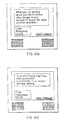
- Fig. 10a illustrates an initial screen that allows the user to enter selections by simply touching of the screen.
- Fig. 10b provides instructions for the desired method of payment.
- payment may be made by credit card, however, the apparatus 10 may be provided with a variety of payment means for making payment, including the appropriate cash receiving mechanisms (not shown) and credit card receiving means for allowing debiting of credit card accounts. Any payment means may be provided to apparatus 10.
- Fig. 10c illustrates and provides directions on how the film cartridge 18 may be inserted into the apparatus 10.
- Fig. 10d provides instructions to the user and advises the amount of time remaining for processing.
- Fig. 10e While the apparatus 10 develops the images in a relatively short period of time, during the development process there is provided an opportunity to display the various products available and/or allow the consumer to do other things with his account as shown in Fig. 10e. For example, using a unique customer ID to review images that may have been previously stored in the customer's account. Referring to Fig. 10f, the consumer is advised if the film 13 has been developed and that it is ready for review. Fig. 10g illustrates various order options and the images that have been developed. It is, of course, understood that the display device 42 may provide as many appropriate options as desired and provide the images in any desired format. In the particular embodiment illustrated, all the images developed on film 13 are shown as small images (imagettes) 102.
- Fig. 1 Oh illustrates how a selected portion of several images will be produced as an album page, illustrated by item 104, so that the consumer will have some idea as to how the ordered product will look.
- the receipt 81 can include a variety of information, for example, a unique order number 108, a copy of each of the images that were selected for ordering, and image ID 109 associated with each image.
- the image ID 109 is a bar code which is unique for each image.
- the order number 108 and image ID 109 may be provided in any desired format, preferably a machine readable format. Additional information may be provided on receipt 81, such as date and any other appropriate information that may be required or deemed desirable. For example, but not by way of limitation, the location at which the apparatus was used, the type of film, the type of processing used for development, the date on which the machine provided the processing, customer preferences, custom name, address etc.
- a customer places a photofinishing order through the use of the input device at apparatus 10 for fulfilling of the customer order at a central printing station (product fulfillment location) remote from apparatus 10.
- the customer order is electronically forwarded to the remote printing station where the order is filled.
- the completed customer order is then forwarded by any appropriate means to the customer at a designated location, such as the customer's home, the store where the apparatus 10 is located.
- the order may be sent by mail, courier or by any other means.
- the printer 80 may also provide an order form 106, such as illustrated in Fig. 12.
- the order form 106 is similar to receipt 81 but also includes order selection boxes 119 that can be filled out by the customer.
- the form 16 can then be fed into the apparatus through a receipt order slot 110 for reading and placement of the order.
- the order is then submitted to the appropriate location for completion.
- This system allows the user to take the images home and decide on the order as to whether or not additional copies or modifications are to be made. Additionally, should the user have a personal computer, the receipt ID 108 may be used to provide information for allowing the customer to have access to apparatus 10, and thereby placing the order electronically over the Internet, or allowing the consumer to have access to the images and making further modifications and then making the appropriate request for image products.
- image products There are a variety of different image products that may be ordered, included but not by way of limitation, hardcopy prints on photographic paper or other media, album pages containing a plurality of images on one or both sides, a photo CD, computer disks containing images, or any other image product that may be produced now or by future technology.
- FIG. 13 and 14 there is illustrated a modified apparatus 210 made in accordance with the present invention.
- apparatus 210 is a customer self service kiosk independent of a retail sales person or operator.
- Fig. 14 is an exploded view of the apparatus 210 of Fig. 13 illustrating its various sections.
- Section 212 is similar to the apparatus 10, with like numerals indicating like parts and operation.
- Section 214 illustrates a first printer section for printing images onto a web 216 that is wound about a core 218.
- the printer section 214 includes an inkjet printhead 220 for printing onto web 216 as it passes thereby.
- a cutter 222 is provided for cutting of the web into individual image prints 224.
- the prints 224 are delivered to a delivery tray section 226 whereby a customer may remove the order upon completion.
- the apparatus 210 includes a second printing system 230 for printing onto precut sheets 232 for printing large format images.
- the printer system 230 is a large format inkjet printer capable of printing images onto sheets ranging in size from 24" or 36" wide to 108" in length.
- An example of a suitable large format inkjet printer is sold by the Eastman Kodak Company under the tradename Kodak Digital Science 1000 PS large format inkjet printer.
- the printer system 230 provides the appropriate image in response to the image order entered into by the customer. While in the particular embodiment illustrated where an inkjet printer system is illustrated, it is to be understood that any other desired type of printing system may be utilized, for example, but not by way of limitation, thermal printers.
- FIG. 15 there is illustrated another modified photofinishing apparatus 310 made in accordance with the present invention.
- the apparatus 310 is similar to the apparatus 10, with like numerals indicating like parts and operation, except that instead of being provided as a single integrated apparatus, apparatus 310 is broken down into various separate components.
- the system 310 includes a separate developer section 312 wherein a cartridge 18 may be placed for developing and scanning in the same manner previously discussed with respect to apparatus 10.
- a separate display device 42 is provided which is connected by appropriate wires or otherwise to computer 314.
- Computer 314 is connected by appropriate wires or otherwise to various output devices, for example; a digital printer 316 which can be used for printing of the customer image order; a CD reader/writer 318 which is capable of reading digital information provided by a customer and/or providing of an output product to be delivered to a customer; a modem 320 may be provided for communication to various other devices remote for printing of image products, or for receiving of image orders; and a second printer 322 may be provided for printing of a receipt 324.
- the receipt 324 can used by the customer for confirmation of the order when the image order is received.
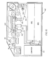
- FIG. 16 there is illustrated a modified developing apparatus 410 made in accordance with the present invention.
- the apparatus 410 is similar to developing system 12, with like numerals indicating like parts and operation.
- a nozzle spray system for providing of appropriate processing solution directly onto the photographic film 18.
- a pair of nozzles 412, 414 are provided for applying an appropriate activator and stabilizer, respectively, onto the film 13 as it is thrust past said nozzles 412, 414.
- a dryer 416 is provided for drying of film 13.
- the dryer 416 includes a blower 418 and a heating element 420, such that heated air is impinged upon the film 13 as it passes thereby.
- the nozzle 412 is connected to a first reservoir 422 containing first processing and nozzle 414 is connected to a second reservoir 424 containing a second processing solution. It is, of course, to be understood that as many or few nozzles may be provided as appropriate for providing of the appropriate processing solution for processing of the photosensitive media.
- a vibrating mechanism 430 is provided for enhancing the speed of processing.
Abstract
A method and apparatus for developing a strip of photosensitive media (13) having image exposure area having an undeveloped exposed portion thereon. The apparatus includes a transport mechanism for moving the photosensitive media along a processing path (34); and a mechanism positioned along the processing path for selectively applying a coating of the processing solution only on the undeveloped exposed portion of the strip of photosensitive media. The apparatus further includes sensors (39) for determining the location of the undeveloped exposed portion of the image exposure area. A scanner (40) may be provided for scanning the strip of photosensitive media so as to obtain a digital record of the images developed thereon.
Description
- The present invention relates to photofinishing of photosensitive material, and more particularly, to a method and apparatus for photofinishing a photosensitive material using an apparently dry development process.
- Typical photofinishing of photosensitive media, such as film, comprises the development of the photosensitive media using wet processing system followed by printing of the image onto a second photosensitive media, which is also processed using a conventional wet process system. Conventional wet process comprises the passing of the film through a plurality of processing tanks, each tank containing a processed solution. Such conventional wet processing is relatively time-consuming, restricted to specific types of films, must be carefully monitored and maintained in order to ensure consistent high quality, special care must be taken in the using and disposal of the processing solutions.
- There has also been suggested in the prior art the providing of a fully automated photofinishing device wherein a customer can walk up to the device, insert a film cartridge, and have the enclosed film processed. An example of such a system is disclosed in U.S. Patent 5,113,351, wherein a conventional wet processing system is utilized. As previously mentioned, this type of wet processing system requires careful maintenance of the chemistry in order to insure consistent high quality. Additionally, the wet processing is limited to typically one type chemistry used for processing of a particular type film. In addition, typical wet processing systems are not suitable for doing partial roll development.
- There has also been suggested in the prior art a Bi-Mat development system whereby 35mm instant color slide film is developed. An example of such a system is the PolaChrome CS 35mm instant color slide film, which incorporates a black and white emulsion layer provided on a substrate and an additive color screen which is used to produce color images. Once the film has been exposed, it is placed in a device whereby a donor strip is coated with a processing solution, which is then caused to come in contact with the exposed film through use of a pair of laminating rollers. Since the emulsion is a black and white emulsion, only a single processing solution is applied. A problem with this system is that it sacrifices film speed, D-min density, an image quality in order to obtain visually acceptable slide image.
- U.S. Patent 5,627,016 discloses a system similar to the Bi-Mat system, which is relatively simple and low cost. While the system disclosed therein provides an improvement over the PolaChrome CS 35mm system, it is not suitable for use with film having substantially different chemistry and is not designed for doing partial roll developing and printing.
- The present invention provides a method and apparatus for photofinishing a variety of different type photosensitive materials using a single, simple low-cost device. Additionally, the system allows for partial roll development and allows the providing of a large variety of different custom image products to be produced.
- In accordance with one aspect of the present invention there is provided an apparatus for developing a strip of photosensitive media having image exposure area having an undeveloped exposed portion thereon, comprising:
- a transport mechanism for moving the photosensitive media along a processing path; and
- a mechanism positioned along the processing path for selectively applying a coating of the processing solution only on the undeveloped exposed portion of the strip of photosensitive media.
-
- In accordance with another aspect of the present invention there is provided an apparatus for developing a strip photosensitive media having image exposure area having an undeveloped exposed portion thereon, comprising:
- a transport mechanism for moving the photosensitive media along a processing path;
- means for determining the location of the undeveloped exposed portion of the image exposure area; and
- a mechanism positioned along the processing path for applying a coating of the processing solution on the undeveloped exposed portion of the photosensitive.
-
- In accordance with yet another aspect of the present invention there is provided a method for developing a strip of photosensitive media provided in a film cartridge, the photosensitive media having a back side, a front side, and an emulsion layer on the front side, comprising the steps of:
- a) moving the filmstrip along a film path;
- b) applying a developing solution on the emulsion layer so as to develop any exposed images present on the strip of film media;
- c) scanning the strip of photosensitive media after the exposed images have been developed; and
- d) cleaning the filmstrip prior to returned to the cartridge.
-
- In accordance with yet another aspect of the present invention there is provided a method for developing a strip photosensitive media having image exposure area having an undeveloped exposed portion thereon, comprising the steps of:
- transporting the photosensitive media along a processing path;
- determining the location of the undeveloped exposed portion of the image exposure area; and
- applying a coating of the processing solution on the undeveloped exposed portion of the photosensitive
-
- In still yet another aspect of the present invention there is provided a method for developing a strip photosensitive media having image exposure area having an undeveloped exposed portion thereon, comprising the steps of:
- moving the photosensitive media along a processing; and
- selectively applying a coating of the processing solution only on the undeveloped exposed portion of the photosensitive.
-
- These and other advantages of the present invention will be more clearly understood and appreciated from a review of the following detailed description and appended claims, and by reference to the accompanying drawings.
- In the detailed description of the preferred embodiments of the invention presented below, reference is made to the accompanying drawings in which:
- Fig. 1 is a perspective view of an apparatus made in accordance with the present invention partially broken away illustrating the components in schematic form;
- Fig. 2 is an enlarged view of the development section of the apparatus of Fig. 1 illustrating clearing of the donor web;
- Fig. 3 is a view similar to Fig. 2 illustrating cleaning of the film;
- Fig. 4 is a partial diagrammatic representation of the apparatus of Fig. 1 illustrating the rewinding of the film back into the cartridge;
- Fig. 5 is a view similar to Fig. 4 illustrating the film almost fully rewound back into the cartridge;
- Fig. 6 is a modified development section mode in accordance with the present invention;
- Fig. 7 is a modified donor web and drive used in the apparatus of Fig. 6;
- Fig. 8 is another modified development section mode in accordance with the present invention;
- Fig. 9a-9c illustrates still another modified apparatus mode in accordance with the present invention;
- Figs. 10a-10h illustrates various screens used to control operation of the apparatus and for ordering of image products;
- Fig. 11 is a receipt which is printed by the apparatus of the present invention;
- Fig. 12 is a second embodiment of a receipt printed by the apparatus of the present invention which can be used for ordering products and/or services;
- Fig. 13 is a perspective view of a modified apparatus made in accordance with the present invention;
- Fig. 14 is an exploded view of the apparatus of Fig. 10;
- Fig. 15 is a schematic diagram of another embodiment of a system made in accordance with the present invention; and
- Fig. 16 is a schematic diagram of still another modified embodiment of an apparatus made in accordance with the present invention.
-
- Referring to Figs. 1-5, there is illustrated schematically a
photofinishing apparatus 10 made in accordance with the present invention. Preferably as illustratedapparatus 10 is a customer self service kiosk which does not require retail sale persons or an operator. Theapparatus 10 includes adevelopment section 12, as shown separately by Figs. 2-5, for developing exposed images on a photosensitive media. In the particular embodiment illustrated, thedevelopment section 12 is designed to be a Bi-Mat development system. For the purposes of the present invention, a Bi-Mat type development system shall be considered a system which utilizes a single processing solution to fully develop the photosensitive emulsion layer on a supporting substrata. In the particular embodiment illustrated, thephotofinishing apparatus 10 is designed to processphotographic film 13 having afront side 14 and a back side 15 with a photosensitive emulsion layer on the front 14. Theapparatus 10 includes aholding mechanism 16 for holding afilm cartridge 18, which is designed to holdphotographic film 13. In the particular embodiment illustrated, thefilm cartridge 18 is of the thrust film type, such as illustrated in U.S. Patent Nos. 5,200,777 and 5,031,852 which incorporates the references in their entirety. In such thrust film cartridges, the film can be automatically thrust out of or back into thefilm cartridge 18. Thephotographic film 13 is helically wound about a film core (not shown), which is rotatably mounted to thecartridge 18. A light valve (also not shown) is rotatably mounted tocartridge 18 adjacent an opening incartridge 18. When the light valve is in theopen position film 13 may to be either thrust out, or thrust back into thecartridge 18 by rotation of the core in the appropriate direction. A transport mechanism is provided for movingfilm 13 along afilm processing path 34. In the particular embodiment illustrated, the transport mechanism for moving the film motor (not shown) provided inapparatus 10 engages and rotates the core of the cartridge. - In the particular embodiment illustrated, the holding mechanism includes an
opening 20 having an inner configuration designed to mate with the outer configuration of thefilm cartridge 18. In the embodiment illustrated theopening 20 is oriented in a direction substantially perpendicular to processingpath 34. This allows the end of the core ofcartridge 18 to easily engage the motor used to rotate the core. Once properly engaged in theopening 20,film 13 can be thrust out of, or intocartridge 18 as appropriate. Asensor 19 is provided for reading the film DX code oncartridge 18. The DX code contains information that can be used byapparatus 10 for determining if thefilm 13 contained therein is suitable for processing byapparatus 10 and for selecting the appropriate algorithm for processing of the scanned image data as discussed later herein. -
Development section 12 includes asupply reel 22 having adonor web 24 wound around a core 25. Thedonor web 24 is unwound fromsupply reel 22 through afilm processing section 26 by a motor (not shown) which drives thecore 27 of a take-up reel 28. A pair ofguide rollers 30 provides for guidingdonor web 24 through theprocessing section 26. Abacker member 32 is provided betweenguide rollers 30 for providing a supporting surface fordonor web 24, as discussed later herein. - The
photographic film 13, when thrust out of thecartridge 18, is passed along aprocessing path 34, which extends through thefilm processing section 26 and terminates into afestoon 36 where the film is temporarily stored. Recently, an advanced photosystem (APS) has been introduced where a thin magnetic layer is provided on a photographic film for containing photofinishing and other information thereon. Disposed adjacent thecartridge 18 along theprocessing film path 34 there is provided a magnetic read/write head 38 for reading any information contained magnetically on the film and/or for writing magnetic information thereon. Aninfrared sensor 39 is provided adjacent read/write head 38. Infrared sensors can see through unprocessed film without exposing it. Processed film and unprocessed film provide different "IR" signatures. Thus it is possible to detect if the film has been fully or partially developed. Adigital scanner 40, preferably of a high resolution, is provided for scanning images developed onfilm 13. Thescanner 40, in the embodiment illustrated, is a linear CCD array (charge coupled device), which can scan the images and thereby produce a digital record of the images scanned. It is to be understood thatscanner 40 may be any appropriate type digital scanner and is not limited to a CCD device. The image information obtained fromscanner 40 is passed onto acomputer 84, where the digital information obtained may be manipulated as appropriate. The digital images obtained byscanner 40 are displayed ondisplay device 42, which in the particular embodiment illustrated, is a CRT. Thus, the user of theapparatus 10 can readily view images that have been developed onfilm 13. - A processing solution application system 50 is provided for applying a processing solution onto the
donor web 24, which is then applied to thephotographic film 13 as it passes through thefilm processing section 26. In the particular embodiment illustrated, the processing solution application system 50 includes areservoir 52, which contains a processing/activator solution 54. Anapplicator nozzle 56 is provided for applying processing/activator solution 54 obtained fromreservoir 52 ontodonor web 24. In the particular embodiment illustrated, a pump (not shown) is used for supplying the processing/activator solution tooutlet 58 ofnozzle 56 which is then sprayed on todonor web 24. Thenozzle outlet 58 is positioned at a point with respect to theweb 24 which is before theweb 24 comes in contact with thefilm 13. In the particular embodiment illustrated, thenozzle outlet 58 is positioned at a point adjacent theweb 24 just after it has been taken from thesupply reel 22. However, thenozzle outlet 58 may be located at any point before theweb 24contacts film 13. In the preferred embodiment illustrated the processing system 50 is provided areplaceable cartridge 51. Thus, any type chemistry may be provided inapparatus 10 capable of being applied on to a web. Thecartridge 51 is provided with a machinereadable code 53 that can be read by anappropriate sensor 55 provided inapparatus 10. Thesensor 55 is connected tocomputer 84 inapparatus 10 which can determine what type developing chemistry has been provided toapparatus 10. - The
processing section 26 includes apressure applying mechanism 44, which is used to bias thefilm 13 towarddonor web 20 as it passes through theprocessing section 26 such that it will be in imminent contact with thedonor web 24 so that theprocessing solution 54 will be transferred fromdonor web 24 ontofilm 13 for development of the exposed images thereon. In the particular embodiment illustrated, thepressure applying mechanism 44 includes a plurality ofrollers 46 having abelt 48 extending there-around. In the particular embodiment illustrated, the rollers are free wheeling such that thebelt 44 will move along with thefilm 13 as it is being thrust from the cartridge intofestoon 36. - A
cleaning mechanism 60 is provided for cleaningdonor web 24 and/orfilm 13 as described later herein. Thecleaning mechanism 60 includes asupport plate 62 having asupply reel 64 containing a cleaningweb 66 made of a material capable of cleaning thedonor web 24 and/orfilm 13. The cleaningweb 66 is composed of an absorbent lintless fabric imbibed in a neutralizing agent such as a dilute form of acetic acid. The cleaningweb 66 is guided about a plurality ofguide rollers 68 and terminates in a take-up reel 70. In the particular embodiment illustrated, thesupply reel 62 and take-up reel 70 are each rotatably mounted to thesupport plate 62 and are connected to respective drive motors, not shown, which allow the cleaningweb 66 to be moved along cleaning path 72 formed by theguide rollers 68 in either direction. Thus, the cleaningweb 66 may be wound onto the take-up reel 70, or in certain situations, driven in the reverse direction and rewound back onto thesupply reel 64. Thecleaning mechanism 60 includes a moving mechanism (not shown) comprised of two electrically energized solenoids to selectively move the cleaningweb 66 into contact with either theprocessing web 24 or thefilm strip 13 by moving thesupport plate 62 in the directions indicated byarrows web 66 ofcleaning mechanism 60 may be in contact with thedonor web 24 and/or forfilm 13. Therollers 68 are designed so as to provide afirst contact section 76, such that when the cleaning mechanism is moved in a first direction towardweb 24, the cleaningweb 66 will be in contact with thedonor web 26 as illustrated in Fig. 2. The path 72 includes asecond contact section 78, such that when thecleaning mechanism 60 is moved in a second direction towardfilm 13, thesecond contact section 78 contacts thefilm 13 as illustrated in Fig. 3. Generally, thecleaning mechanism 60 will be cleaning thefilm 13 orweb 66 at different times. However, if desired, thefilm 13 anddonor web 24 may be cleaned at the same time. The cleaning mechanism is, of course, moved in the opposite direction for disengaging from thefilm 13 ordonor web 24. - A
printer 80 is provided for printing out of a customer order receipt 81 (see Fig. 11), as will be discussed later on herein.Apparatus 10 further includes akeypad 82 for allowing entry of information by the user to the apparatus, for example order information. Theapparatus 10 may include any other data entry means for allowing entry of information. For example, but not by way of limitation, thedisplay device 42 may be of the touch screen type whereby simply touching the viewing screen in the appropriate location, information may be entered into theapparatus 10. Thecomputer 84 obtains information from the various components and sensors as is customarily done in such devices. For example, but not by way of limitation,computer 84 is appropriately connected with the magnetic read/write head 38, thescanner 40,printer 80,keypad 82 andCRT 42. Thecomputer 84 is also used to control the general operation ofapparatus 10 and all the other components, sensor, motors and controls inapparatus 10. Thereceipt 81 may include a variety of information, for example but not by way of limitation, information setting forth what was ordered, instructions provided by the customer, the cost of the order, a low resolution copy of each of the images ordered, and unique customer ID. - The
apparatus 10 includes a plurality of different type devices whereby other information, including image and customer order information, may be entered. Image information as previously described is entered intoapparatus 10 by supplying film that is digitally scanned. However, image information may be entered into theapparatus 10 by a variety of other means. For example, but not by way of limitation, a CD readmechanism 86, may be provided for reading of information provided on a CD, a computer disk reader/writer 88 may be provided for reading and writing information onto a standard computer disk, flashmemory card reader 90 for reading flash memory cards, or by an appropriate communication link using a modem as is well known. It is, of course, understood that the image data may be obtained in any appropriate digital form as presently available, or may become available. - In order to better understand the present invention, a description of the operation of
apparatus 10 will now be discussed. - A
film cartridge 18 containing a strip of exposed, butundeveloped film 13, is provided and placed in holdingmechanism 16. The DX code is read bysensor 19 so as to determine the type of film present within thefilm cartridge 18. This information is passed on tocomputer 84 to determine iffilm 13 may be processed by the processing solution contained inapparatus 10. Additionally, knowing the particular film type and chemistry inapparatus 10, an appropriate image manipulation software program may be applied bycomputer 84 to correct and/or adjust the images read byscanner 40. Such algorithm may be easily determined by knowing the original type of film, the processing solution the film was originally designed to be processed by and the affect that the processing solution present in the device will have on the film. Thus, even if the processing solution present inapparatus 10 was not designed to be used with or is not totally compatible with thefilm 13 within thecartridge 18, appropriate digital images may be obtained the by applying appropriate image modification algorithms to the scanned digital image data. Thus, images may be obtained as if the film was processed by a processing solution for which is was designed to be processed. In addition, since the film will be digitally scanned for obtaining of the image data, the film may be of the type that is not designed for optical printing, but designed only for scanning and printing thereafter. Thus providing additional latitude in the manufacture of the film. Potentially allowing for less expensive to manufacture films. If thefilm 13 within thecartridge 18 is compatible with the chemistry available, thefilm 13 is allowed to be processed byapparatus 10. Thesensor 19 may also advise whether or not the film is capable of containing magnetically encoded information. If so, themagnetic head 38 will read appropriate information thereon and take appropriate action as required. Appropriate motors are activated for opening of the light valve of thefilm cartridge 18 and for thrusting of thefilm 13 out of thecartridge 18 alongfilm processing path 34. An appropriate drive motor (not shown) is activated for moving of thedonor web 24 fromsupply reel 22 through thefilm processing section 26 to take-up reel 28 in coordination with the movement of thefilm 13. At the same time,processing solution 54 is drawn fromreservoir 52 and passed on throughapplicator nozzle 56 throughnozzle outlet 58 onto thedonor web 24 so as to apply an appropriate processing solution thereon. The amount of processing solution applied todonor web 24 is controlled such that substantially no processing solution drips or falls fromdonor web 24. Thedonor web 24 is appropriately advanced such that the donor web having the processing solution therein will appropriately contact the portion of thephotographic film 13 having images thereon. Therefore, thedonor web 24 may need to be initially transported prior to the film reaching the film processing section. A thin layer of developing solution is applied to the surface of thedonor web 24, which will come in contact with the emulsion side of the film. As the emulsion on the film ondonor web 24 andfilm 13 pass through theprocessing section 26, pressure is applied bypressure application mechanism 44, causing the emulsion side of thefilm 13 to be forced against the backing member 45 (see Figs. 1-3). By the time thefilm 13 reaches the end of thefilm processing section 26, thefilm 13 will have subjected to a sufficient amount of processing solution for development of the latent images. - After the
film 13 has been completely processed, thepressure application mechanism 44 is withdrawn as illustrated in Figs. 4 and 5 and thefilm 13 is rewound back intothrust film cartridge 18. As thefilm 13 is rewound back into thecartridge 18, themagnetic head 38 reads any information that may be provided on thefilm 13. Additionally as the film is being retracted intocartridge 18, thescanner 40 will read the image information developed thereon. Prior to thefilm 13 being retracted into thecartridge 18, thecleaning mechanism 60 is positioned as illustrated in Fig. 3. The cleaningweb 66 is moved in the appropriate direction as the film is being retracted thus cleaning thefilm 13, removing any excess processing solution that may be on thefilm 13 which could be detrimental to the film. - An advantage of the system according to the present invention is that it is possible to easily process only a portion of the available exposure area of
film 13 without substantially affecting the unexposed portion of thefilm 13 for later exposure and processing. For the purposes of the present invention, the available exposure area shall mean that portion of the film that is designed to be exposed for capturing of an image. The information that is recorded on thefilm 13 byhead 38 may include information that only a portion of thefilm 13 has been exposed. In which case, thefilm 13 is only thrust out a sufficient distance, such that only the exposed area of thefilm 13 is passed intoprocessing section 26 and only the portion that has been exposed is provided with processing solution. Alternatively,sensor 39 can distinguish between process and unprocessed film, thus allowing only the unprocessed section to be processed. Theapparatus 10 is operated in the same manner previously discussed, except that now during retraction of thefilm 13 back intocartridge 18, the magnetic head will record information that a portion of the film has been developed, so that when the film is again placed inapparatus 10, or other similar device, theapparatus 10 will recognize that only the newly exposed portion of the film need be developed. Therefore, only the remaining exposed non-developed portion will be processed. - In the embodiment illustrated in Figs. 1-5, the
donor web 24 is moved by a motor connected tocore 27 of take-up reel 28. In order to more precisely control the amount of processing solution being applied tofilm 13, it is important to control the amount of movement of thedonor web 24. Referring to Figs. 6 there is illustrated a modified mechanism 130 which is similar toapparatus 10 like numerals indicating like parts and operation. In this embodiment donor web 134 (see Fig. 7) is provided with a plurality of equally spacedperforation 136 along bothsides 138 of thedonor web 134.Perforations 136 engagesprocket wheels 140 used to drivedonor web 134 along theprocessing path 26. The engagement ofsprocket wheels 140 withperforations 136 provides a positive drive whereby substantially no slip can occur. The sprocket wheels are driven by a stepper motor, not shown. By turningsprocket wheels 140 at a precise rate, the positive drive of web 124 will result in a precise amount processing solution being applied toweb 134 and in turn on tofilm 13. - Referring to Fig. 8 there is illustrated a modified application system for use in the
development section 12. In order to accurately meter the amount of processing solution being applied toweb 24, a pressurizedvalve control system 57 is provided. In the particular embodiment illustrated, atube 59 is provided containing an appropriate processing solution, preferably in a generally paste form. Acontrol valve 61 is used for precisely monitoring the amount of processing solution being applied. Whenvalve 61 is in the open state the processing solution will be allowed to go therethrough at a predetermined rate. Aram 63 is pushed bymotor 65 which applies continuous pressure to the contents oftube 59. The amount of time the valve is open will determine the amount of solution being applied. Thevalve 61 is controlled bycomputer 84 so that the required amount of processing solution will be applied toweb 24 and then to film 13. - In order to improve the speed of processing, an
optional heater 96 may be provided for increasing the activity of the processing solution applied to thefilm 13 in thefilm processing section 26. Additionally, if so desired, the backing mechanism may be designed to vibrate, which may also improve the processing speed, or efficiency of the processing solution applied to film 13. - After the film has been processed and scanned, appropriate images may be displayed by
display device 42, allowing the customer to review the images that have been developed and for ordering of hardcopy prints and/or other photographic products, such as photo CD's, computer disks, photo albums. Thereafter, the film cartridge may be deposited directly intoapparatus 10. Referring to Figs 9a-9c there is illustrated a modifieddevelopment section 12 for use inapparatus 10. After the film has been rewound into thecartridge 18, the cartridge may be deposited into a receivingchamber 67 by the opening oftrap door 77 as shown in Fig. 9b. In the embodiment illustrated a motor (not shown) is used to open andclose trap door 77 which is controlled bycomputer 84. After thecartridge 18 has been deposited inchamber 18 the door is returned to it's normal position as shown by Fig 9c. By using the information supplied by the customer, the information read from the cartridge a receipt 81 (see Fig. 11) may be printed for the customer. The cartridge ID can be used for the identifying of the order that the customer has placed. There is no need for an order envelope as all the information for completion of the order has been obtained. - Referring to Figs. 10a-10h, there is illustrated various instructions that may be provided on the
display device 42. Fig. 10a illustrates an initial screen that allows the user to enter selections by simply touching of the screen. Fig. 10b provides instructions for the desired method of payment. In the particular embodiment illustrated, payment may be made by credit card, however, theapparatus 10 may be provided with a variety of payment means for making payment, including the appropriate cash receiving mechanisms (not shown) and credit card receiving means for allowing debiting of credit card accounts. Any payment means may be provided toapparatus 10. Fig. 10c illustrates and provides directions on how thefilm cartridge 18 may be inserted into theapparatus 10. Fig. 10d provides instructions to the user and advises the amount of time remaining for processing. While theapparatus 10 develops the images in a relatively short period of time, during the development process there is provided an opportunity to display the various products available and/or allow the consumer to do other things with his account as shown in Fig. 10e. For example, using a unique customer ID to review images that may have been previously stored in the customer's account. Referring to Fig. 10f, the consumer is advised if thefilm 13 has been developed and that it is ready for review. Fig. 10g illustrates various order options and the images that have been developed. It is, of course, understood that thedisplay device 42 may provide as many appropriate options as desired and provide the images in any desired format. In the particular embodiment illustrated, all the images developed onfilm 13 are shown as small images (imagettes) 102. However, appropriate means may be provided for reviewing one, or as many as desired at a single time. Additionally, the computer may be programmed for allowing the customer to modify any of the images. For example, but not by way of limitation, zooming and/or cropping of the image, color enhancements, or for allowing customization and modification of the image. Fig. 1 Oh illustrates how a selected portion of several images will be produced as an album page, illustrated byitem 104, so that the consumer will have some idea as to how the ordered product will look. -
Printer 80 provides areceipt 81 as is illustrated in Fig. 11. Thereceipt 81 can include a variety of information, for example, aunique order number 108, a copy of each of the images that were selected for ordering, andimage ID 109 associated with each image. In the embodiment illustrated theimage ID 109 is a bar code which is unique for each image. Theorder number 108 andimage ID 109 may be provided in any desired format, preferably a machine readable format. Additional information may be provided onreceipt 81, such as date and any other appropriate information that may be required or deemed desirable. For example, but not by way of limitation, the location at which the apparatus was used, the type of film, the type of processing used for development, the date on which the machine provided the processing, customer preferences, custom name, address etc. - In the particular embodiment illustrated, a customer places a photofinishing order through the use of the input device at
apparatus 10 for fulfilling of the customer order at a central printing station (product fulfillment location) remote fromapparatus 10. Preferably the customer order is electronically forwarded to the remote printing station where the order is filled. The completed customer order is then forwarded by any appropriate means to the customer at a designated location, such as the customer's home, the store where theapparatus 10 is located. The order may be sent by mail, courier or by any other means. Theprinter 80 may also provide anorder form 106, such as illustrated in Fig. 12. Theorder form 106 is similar toreceipt 81 but also includesorder selection boxes 119 that can be filled out by the customer. Theform 16 can then be fed into the apparatus through areceipt order slot 110 for reading and placement of the order. The order is then submitted to the appropriate location for completion. This system allows the user to take the images home and decide on the order as to whether or not additional copies or modifications are to be made. Additionally, should the user have a personal computer, thereceipt ID 108 may be used to provide information for allowing the customer to have access toapparatus 10, and thereby placing the order electronically over the Internet, or allowing the consumer to have access to the images and making further modifications and then making the appropriate request for image products. - There are a variety of different image products that may be ordered, included but not by way of limitation, hardcopy prints on photographic paper or other media, album pages containing a plurality of images on one or both sides, a photo CD, computer disks containing images, or any other image product that may be produced now or by future technology.
- As previously discussed, images are forwarded to a central printing station where the order is completed and then forwarded to the consumer. However, the present invention is not so limited. Referring to Figs. 13 and 14, there is illustrated a modified
apparatus 210 made in accordance with the present invention. In the embodiment illustratedapparatus 210 is a customer self service kiosk independent of a retail sales person or operator. Fig. 14 is an exploded view of theapparatus 210 of Fig. 13 illustrating its various sections.Section 212 is similar to theapparatus 10, with like numerals indicating like parts and operation.Section 214 illustrates a first printer section for printing images onto aweb 216 that is wound about a core 218. In the particular embodiment illustrated, theprinter section 214 includes aninkjet printhead 220 for printing ontoweb 216 as it passes thereby. Acutter 222 is provided for cutting of the web into individual image prints 224. Preferably, theprints 224 are delivered to a delivery tray section 226 whereby a customer may remove the order upon completion. - In the embodiment illustrated in Figs. 13 and 14, the
apparatus 210 includes asecond printing system 230 for printing ontoprecut sheets 232 for printing large format images. In the particular embodiment illustrated, theprinter system 230 is a large format inkjet printer capable of printing images onto sheets ranging in size from 24" or 36" wide to 108" in length. An example of a suitable large format inkjet printer is sold by the Eastman Kodak Company under the tradename Kodak Digital Science 1000 PS large format inkjet printer. Theprinter system 230 provides the appropriate image in response to the image order entered into by the customer. While in the particular embodiment illustrated where an inkjet printer system is illustrated, it is to be understood that any other desired type of printing system may be utilized, for example, but not by way of limitation, thermal printers. - Referring to Fig. 15, there is illustrated another modified
photofinishing apparatus 310 made in accordance with the present invention. Theapparatus 310 is similar to theapparatus 10, with like numerals indicating like parts and operation, except that instead of being provided as a single integrated apparatus,apparatus 310 is broken down into various separate components. In the particular embodiment illustrated, thesystem 310 includes aseparate developer section 312 wherein acartridge 18 may be placed for developing and scanning in the same manner previously discussed with respect toapparatus 10. However, in this embodiment, aseparate display device 42 is provided which is connected by appropriate wires or otherwise tocomputer 314.Computer 314 is connected by appropriate wires or otherwise to various output devices, for example; adigital printer 316 which can be used for printing of the customer image order; a CD reader/writer 318 which is capable of reading digital information provided by a customer and/or providing of an output product to be delivered to a customer; a modem 320 may be provided for communication to various other devices remote for printing of image products, or for receiving of image orders; and asecond printer 322 may be provided for printing of areceipt 324. Thereceipt 324 can used by the customer for confirmation of the order when the image order is received. - Referring to Fig. 16, there is illustrated a modified developing
apparatus 410 made in accordance with the present invention. Theapparatus 410 is similar to developingsystem 12, with like numerals indicating like parts and operation. In this embodiment, instead of providing adonor web 24 for application of processing solution, there is provided a nozzle spray system for providing of appropriate processing solution directly onto thephotographic film 18. In particular, a pair ofnozzles film 13 as it is thrust past saidnozzles dryer 416 is provided for drying offilm 13. In particular, thedryer 416 includes ablower 418 and aheating element 420, such that heated air is impinged upon thefilm 13 as it passes thereby. In the particular embodiment illustrated, thenozzle 412 is connected to afirst reservoir 422 containing first processing andnozzle 414 is connected to asecond reservoir 424 containing a second processing solution. It is, of course, to be understood that as many or few nozzles may be provided as appropriate for providing of the appropriate processing solution for processing of the photosensitive media. A vibratingmechanism 430 is provided for enhancing the speed of processing.
Claims (11)
- An apparatus for developing a strip of photosensitive media having image exposure area having an undeveloped exposed portion thereon, comprising:a transport mechanism for moving the photosensitive media along a processing path; anda mechanism positioned along said processing path for selectively applying a coating of said processing solution only on the undeveloped exposed portion of said strip of photosensitive media.
- An apparatus according to claim 1 wherein said mechanism for applying a coating comprises a donor web on which said processing solution is first applied and then transfer on to said photosensitive media
- An apparatus according to claim 1 further comprising a cleaning mechanism positioned between said thrust film cartridge and said mechanism for applying processing solution onto said photosensitive media so that excess processing solution will be cleaned from said photosensitive media prior to being returned to said thrust film cartridge.
- An apparatus according to claim 1 wherein said donor web is provided with a plurality of perforations which can be used for advancing or retracting the donor web.
- An apparatus according to claim 1 further comprising a heater for applying heat to said processing solution on said film so as to increase the speed of development of film.
- An apparatus for developing a strip photosensitive media having image exposure area having an undeveloped exposed portion thereon, comprising:a transport mechanism for moving the photosensitive media along a processing path;means for determining the location of said undeveloped exposed portion of the image exposure area; anda mechanism positioned along said processing path for applying a coating of said processing solution on the undeveloped exposed portion of said photosensitive.
- An apparatus according to claim 6 wherein said means for determining the location of said undeveloped exposed portion of the image exposure area comprises a magnetic head for reading information on said photosensitive media.
- An apparatus according to claim 6 wherein said means for determining the location of said undeveloped exposed portion of the image exposure area comprises a sensor for scanning said film for determining the areas of said photosensitive that have been exposed.
- A method for developing a strip of photosensitive media provided in a film cartridge, said photosensitive media having a back side, a front side, and an emulsion layer on the front side, comprising the steps of:a) moving said filmstrip along a film path;b) applying a developing solution on said emulsion layer so as to develop any exposed images present on said strip of film media;c) scanning said strip of photosensitive media after said exposed images have been developed; andd) cleaning said filmstrip prior to returned to said cartridge.
- A method for developing a strip photosensitive media having image exposure area having an undeveloped exposed portion thereon, comprising the steps of:transporting the photosensitive media along a processing path;determining the location of said undeveloped exposed portion of the image exposure area; andapplying a coating of said processing solution on the undeveloped exposed portion of said photosensitive
- A method for developing a strip photosensitive media having image exposure area having an undeveloped exposed portion thereon, comprising the steps of:moving the photosensitive media along a processing; andselectively applying a coating of said processing solution only on the undeveloped exposed portion of said photosensitive.
Applications Claiming Priority (2)
| Application Number | Priority Date | Filing Date | Title |
|---|---|---|---|
| US09/451,732 US6174094B1 (en) | 1999-11-30 | 1999-11-30 | Method and apparatus for photofinishing a photosensitive media and/or ordering of image products |
| US451732 | 1999-11-30 |
Publications (1)
| Publication Number | Publication Date |
|---|---|
| EP1107060A1 true EP1107060A1 (en) | 2001-06-13 |
Family
ID=23793477
Family Applications (1)
| Application Number | Title | Priority Date | Filing Date |
|---|---|---|---|
| EP00204078A Withdrawn EP1107060A1 (en) | 1999-11-30 | 2000-11-20 | Photofinishing method and apparatus |
Country Status (5)
| Country | Link |
|---|---|
| US (4) | US6174094B1 (en) |
| EP (1) | EP1107060A1 (en) |
| JP (1) | JP2001166450A (en) |
| CN (1) | CN1298117A (en) |
| CA (1) | CA2326604A1 (en) |
Cited By (1)
| Publication number | Priority date | Publication date | Assignee | Title |
|---|---|---|---|---|
| CN104298067A (en) * | 2014-09-24 | 2015-01-21 | 中冶宝钢技术服务有限公司 | Portable developing machine |
Families Citing this family (17)
| Publication number | Priority date | Publication date | Assignee | Title |
|---|---|---|---|---|
| US6650831B1 (en) * | 1999-10-15 | 2003-11-18 | James Thompson | Method of providing access to photographic images over a computer network |
| US6435562B1 (en) * | 1999-11-30 | 2002-08-20 | Eastman Kodak Company | Method and apparatus for making an album page |
| US6554504B2 (en) * | 1999-12-30 | 2003-04-29 | Applied Science Fiction, Inc. | Distributed digital film processing system and method |
| US6599036B2 (en) * | 2000-02-03 | 2003-07-29 | Applied Science Fiction, Inc. | Film processing solution cartridge and method for developing and digitizing film |
| WO2001095028A2 (en) * | 2000-02-03 | 2001-12-13 | Applied Science Fiction | Method and system for self-service film processing |
| US6558051B2 (en) * | 2000-03-17 | 2003-05-06 | Konica Corporation | Film scanning device provided in automatic developing apparatus |
| EP1158766A1 (en) * | 2000-05-24 | 2001-11-28 | Hewlett-Packard Company, A Delaware Corporation | Method and apparatus for selection of items |
| JP2002032291A (en) * | 2000-07-19 | 2002-01-31 | Canon Inc | Information processor, image processor, print request processing method for information processor and print demand processing method for image processor |
| US6745186B1 (en) * | 2000-08-17 | 2004-06-01 | Eastman Kodak Company | Product and method for organizing and searching digital images |
| US6480673B2 (en) * | 2000-12-29 | 2002-11-12 | Gateway, Inc. | Instant photo kiosk |
| GB0103834D0 (en) * | 2001-02-16 | 2001-04-04 | Eastman Kodak Co | Photo-finishing |
| US20020191077A1 (en) * | 2001-05-28 | 2002-12-19 | Hiroaki Takano | Image forming apparatus |
| JP2003006483A (en) * | 2001-06-22 | 2003-01-10 | Fuji Color Service Co Ltd | Method, system, and program for photograph order reception, and photographic print generating method |
| US20030020946A1 (en) * | 2001-07-26 | 2003-01-30 | O'hara Sean M. | Printer capable of directly printing using negative or positive film source |
| US6765646B2 (en) * | 2001-09-05 | 2004-07-20 | Noritsu Koki Co., Ltd. | Print-order receiving apparatus |
| US7225739B2 (en) * | 2004-01-21 | 2007-06-05 | Silverbrook Research Pty Ltd | Drying system for use in a printing system |
| US20060126108A1 (en) * | 2004-12-15 | 2006-06-15 | Lexmark International, Inc. | Method, printer, and storage medium for printing a medical image |
Citations (8)
| Publication number | Priority date | Publication date | Assignee | Title |
|---|---|---|---|---|
| US3747493A (en) * | 1972-11-07 | 1973-07-24 | Eastman Kodak Co | Turntable camera-processing apparatus |
| US3778140A (en) * | 1972-02-17 | 1973-12-11 | Polaroid Corp | Photographic system comprising film cassette including self-contained processing apparatus and film drive and projection system controlled thereby |
| US4561745A (en) * | 1983-12-28 | 1985-12-31 | Polaroid Corporation | Method and apparatus for processing both sides of discrete sheets |
| EP0709733A1 (en) * | 1994-10-27 | 1996-05-01 | Eastman Kodak Company | Method and apparatus for processing photosensitive film |
| US5627016A (en) * | 1996-02-29 | 1997-05-06 | Eastman Kodak Company | Method and apparatus for photofinishing photosensitive film |
| US5745811A (en) * | 1996-03-27 | 1998-04-28 | Fuji Photo Film Co., Ltd. | Image recording device, developing device and image recording system |
| WO1998040786A1 (en) * | 1997-03-11 | 1998-09-17 | Polaroid Corporation | Spool caddy for use with processing of roll film by means of applicator webs |
| US5975771A (en) * | 1996-05-17 | 1999-11-02 | Fuji Photo Film Co., Ltd. | Development control method developing apparatus and image exposing apparatus |
Family Cites Families (12)
| Publication number | Priority date | Publication date | Assignee | Title |
|---|---|---|---|---|
| US4021240A (en) | 1975-12-22 | 1977-05-03 | Eastman Kodak Company | Photothermographic and thermographic compositions and uses therefor containing sulfonamidophenol reducing agents and four equivalent color couplers |
| JPS59159144A (en) * | 1983-03-01 | 1984-09-08 | Mochizuki Shoten:Kk | Device for storing exposed film of photographing and developing device |
| US4485294A (en) | 1983-03-18 | 1984-11-27 | Phoenix Medical Corporation | Developer for photothermographic paper |
| JPS62148984A (en) * | 1985-12-23 | 1987-07-02 | Fuji Photo Film Co Ltd | Developer supply device for electrophotographic device |
| US5113351A (en) | 1989-03-29 | 1992-05-12 | Delphi Technology, Inc. | Automated, interactive vending system for products which must be processed |
| US5031852A (en) | 1990-01-12 | 1991-07-16 | Eastman Kodak Company | Film-thrusting cassette |
| US5200777A (en) | 1991-11-04 | 1993-04-06 | Eastman Kodak Company | Film cassette with integrated cassette element lock and light blocking device |
| GB9421940D0 (en) * | 1994-11-01 | 1994-12-21 | Kodak Ltd | Processing apparatus |
| JP3349608B2 (en) | 1994-11-17 | 2002-11-25 | 富士写真フイルム株式会社 | Thermal development color photosensitive material |
| US5587767A (en) | 1995-05-04 | 1996-12-24 | Xerox Corporation | Digital film heat processor and method of developing digital film |
| US5988896A (en) * | 1996-10-26 | 1999-11-23 | Applied Science Fiction, Inc. | Method and apparatus for electronic film development |
| US5840475A (en) | 1996-10-28 | 1998-11-24 | Eastman Kodak Company | Photothermographic element for providing a viewable retained image |
-
1999
- 1999-11-30 US US09/451,732 patent/US6174094B1/en not_active Expired - Fee Related
-
2000
- 2000-03-23 US US09/533,835 patent/US6244761B1/en not_active Expired - Fee Related
- 2000-09-21 US US09/667,058 patent/US6312172B1/en not_active Expired - Fee Related
- 2000-09-21 US US09/666,441 patent/US6322260B1/en not_active Expired - Fee Related
- 2000-11-20 EP EP00204078A patent/EP1107060A1/en not_active Withdrawn
- 2000-11-23 CA CA002326604A patent/CA2326604A1/en not_active Abandoned
- 2000-11-30 JP JP2000365066A patent/JP2001166450A/en active Pending
- 2000-11-30 CN CN00135080A patent/CN1298117A/en active Pending
Patent Citations (8)
| Publication number | Priority date | Publication date | Assignee | Title |
|---|---|---|---|---|
| US3778140A (en) * | 1972-02-17 | 1973-12-11 | Polaroid Corp | Photographic system comprising film cassette including self-contained processing apparatus and film drive and projection system controlled thereby |
| US3747493A (en) * | 1972-11-07 | 1973-07-24 | Eastman Kodak Co | Turntable camera-processing apparatus |
| US4561745A (en) * | 1983-12-28 | 1985-12-31 | Polaroid Corporation | Method and apparatus for processing both sides of discrete sheets |
| EP0709733A1 (en) * | 1994-10-27 | 1996-05-01 | Eastman Kodak Company | Method and apparatus for processing photosensitive film |
| US5627016A (en) * | 1996-02-29 | 1997-05-06 | Eastman Kodak Company | Method and apparatus for photofinishing photosensitive film |
| US5745811A (en) * | 1996-03-27 | 1998-04-28 | Fuji Photo Film Co., Ltd. | Image recording device, developing device and image recording system |
| US5975771A (en) * | 1996-05-17 | 1999-11-02 | Fuji Photo Film Co., Ltd. | Development control method developing apparatus and image exposing apparatus |
| WO1998040786A1 (en) * | 1997-03-11 | 1998-09-17 | Polaroid Corporation | Spool caddy for use with processing of roll film by means of applicator webs |
Cited By (1)
| Publication number | Priority date | Publication date | Assignee | Title |
|---|---|---|---|---|
| CN104298067A (en) * | 2014-09-24 | 2015-01-21 | 中冶宝钢技术服务有限公司 | Portable developing machine |
Also Published As
| Publication number | Publication date |
|---|---|
| CN1298117A (en) | 2001-06-06 |
| US6174094B1 (en) | 2001-01-16 |
| JP2001166450A (en) | 2001-06-22 |
| US6322260B1 (en) | 2001-11-27 |
| US6312172B1 (en) | 2001-11-06 |
| US6244761B1 (en) | 2001-06-12 |
| CA2326604A1 (en) | 2001-05-30 |
Similar Documents
| Publication | Publication Date | Title |
|---|---|---|
| EP1107059B1 (en) | Photofinishing and ordering method and apparatus | |
| US6174094B1 (en) | Method and apparatus for photofinishing a photosensitive media and/or ordering of image products | |
| US5420699A (en) | Processing apparatus for processing information on photographic film | |
| US6394498B1 (en) | Method and apparatus for making an album page | |
| US20020192001A1 (en) | Method and apparatus for making an album page | |
| US6309115B1 (en) | Method and apparatus for photofinishing a photosensitive media and/or ordering of image products | |
| EP1107061A1 (en) | Heat development apparatus | |
| US6229592B1 (en) | Negative film with identification number, and photographic printing apparatus | |
| JPH0545714A (en) | Photographic film | |
| JPH06258719A (en) | Reprinting apparatus of image recorded on photographic film band | |
| JPH07219201A (en) | Photographic processing system | |
| JP2952538B2 (en) | Undeveloped film and film processing equipment | |
| JP3476894B2 (en) | Information printing device | |
| JP2006065075A (en) | Image formation system and hand-over system using same image formation system | |
| JPH0950083A (en) | Photograph processing system | |
| JPH07248599A (en) | Device for receiving photographic processing request | |
| JPH09114081A (en) | Print processing method for photographic film | |
| JPH06313929A (en) | Photographic information output controller | |
| JP2001100366A (en) | Film container, film, camera, automatic developing machine and print forming system | |
| JPH10301211A (en) | Photographic printer | |
| JPH07104454A (en) | Photographic information output control device | |
| JPH103127A (en) | Print producing method and print producing system | |
| JPH07128747A (en) | Picture information output controller | |
| JPH07248598A (en) | Method and device for receiving photographic processing request | |
| JP2001318433A (en) | Instant printer |
Legal Events
| Date | Code | Title | Description |
|---|---|---|---|
| PUAI | Public reference made under article 153(3) epc to a published international application that has entered the european phase |
Free format text: ORIGINAL CODE: 0009012 |
|
| AK | Designated contracting states |
Kind code of ref document: A1 Designated state(s): CH DE FR GB IT LI |
|
| AX | Request for extension of the european patent |
Free format text: AL;LT;LV;MK;RO;SI |
|
| 17P | Request for examination filed |
Effective date: 20011121 |
|
| AKX | Designation fees paid |
Free format text: CH DE FR GB IT LI |
|
| 17Q | First examination report despatched |
Effective date: 20040330 |
|
| STAA | Information on the status of an ep patent application or granted ep patent |
Free format text: STATUS: THE APPLICATION IS DEEMED TO BE WITHDRAWN |
|
| 18D | Application deemed to be withdrawn |
Effective date: 20040810 |