EP1111151A2 - Structural members and associated parts - Google Patents
Structural members and associated parts Download PDFInfo
- Publication number
- EP1111151A2 EP1111151A2 EP00128171A EP00128171A EP1111151A2 EP 1111151 A2 EP1111151 A2 EP 1111151A2 EP 00128171 A EP00128171 A EP 00128171A EP 00128171 A EP00128171 A EP 00128171A EP 1111151 A2 EP1111151 A2 EP 1111151A2
- Authority
- EP
- European Patent Office
- Prior art keywords
- track
- structural member
- elements
- attachment member
- formation
- Prior art date
- Legal status (The legal status is an assumption and is not a legal conclusion. Google has not performed a legal analysis and makes no representation as to the accuracy of the status listed.)
- Granted
Links
- 230000015572 biosynthetic process Effects 0.000 claims abstract description 98
- 230000000717 retained effect Effects 0.000 claims abstract description 5
- 238000005755 formation reaction Methods 0.000 claims description 97
- 230000000903 blocking effect Effects 0.000 claims description 3
- 239000000463 material Substances 0.000 description 7
- 238000010276 construction Methods 0.000 description 4
- 238000003825 pressing Methods 0.000 description 4
- 229910000838 Al alloy Inorganic materials 0.000 description 3
- 238000001125 extrusion Methods 0.000 description 3
- 229920003023 plastic Polymers 0.000 description 3
- 239000004033 plastic Substances 0.000 description 3
- 238000004519 manufacturing process Methods 0.000 description 2
- 229910052751 metal Inorganic materials 0.000 description 2
- 239000002184 metal Substances 0.000 description 2
- 238000000034 method Methods 0.000 description 2
- 229910000831 Steel Inorganic materials 0.000 description 1
- 239000000853 adhesive Substances 0.000 description 1
- 230000001070 adhesive effect Effects 0.000 description 1
- 230000006835 compression Effects 0.000 description 1
- 238000007906 compression Methods 0.000 description 1
- 230000000994 depressogenic effect Effects 0.000 description 1
- 230000000694 effects Effects 0.000 description 1
- 238000003780 insertion Methods 0.000 description 1
- 230000037431 insertion Effects 0.000 description 1
- 238000005304 joining Methods 0.000 description 1
- 238000005096 rolling process Methods 0.000 description 1
- 239000010959 steel Substances 0.000 description 1
- 238000003860 storage Methods 0.000 description 1
- 238000003466 welding Methods 0.000 description 1
Images


Classifications
-
- E—FIXED CONSTRUCTIONS
- E06—DOORS, WINDOWS, SHUTTERS, OR ROLLER BLINDS IN GENERAL; LADDERS
- E06C—LADDERS
- E06C7/00—Component parts, supporting parts, or accessories
- E06C7/18—Devices for preventing persons from falling
- E06C7/186—Rail or rope for guiding a safety attachment, e.g. a fall arrest system
- E06C7/187—Guiding rail
-
- E—FIXED CONSTRUCTIONS
- E04—BUILDING
- E04C—STRUCTURAL ELEMENTS; BUILDING MATERIALS
- E04C3/00—Structural elongated elements designed for load-supporting
- E04C3/02—Joists; Girders, trusses, or trusslike structures, e.g. prefabricated; Lintels; Transoms; Braces
- E04C3/04—Joists; Girders, trusses, or trusslike structures, e.g. prefabricated; Lintels; Transoms; Braces of metal
- E04C3/08—Joists; Girders, trusses, or trusslike structures, e.g. prefabricated; Lintels; Transoms; Braces of metal with apertured web, e.g. with a web consisting of bar-like components; Honeycomb girders
-
- E—FIXED CONSTRUCTIONS
- E04—BUILDING
- E04H—BUILDINGS OR LIKE STRUCTURES FOR PARTICULAR PURPOSES; SWIMMING OR SPLASH BATHS OR POOLS; MASTS; FENCING; TENTS OR CANOPIES, IN GENERAL
- E04H3/00—Buildings or groups of buildings for public or similar purposes; Institutions, e.g. infirmaries or prisons
- E04H3/10—Buildings or groups of buildings for public or similar purposes; Institutions, e.g. infirmaries or prisons for meetings, entertainments, or sports
- E04H3/22—Theatres; Concert halls; Studios for broadcasting, cinematography, television or similar purposes
- E04H3/24—Constructional features of stages
-
- E—FIXED CONSTRUCTIONS
- E04—BUILDING
- E04C—STRUCTURAL ELEMENTS; BUILDING MATERIALS
- E04C3/00—Structural elongated elements designed for load-supporting
- E04C3/02—Joists; Girders, trusses, or trusslike structures, e.g. prefabricated; Lintels; Transoms; Braces
- E04C3/04—Joists; Girders, trusses, or trusslike structures, e.g. prefabricated; Lintels; Transoms; Braces of metal
- E04C2003/0404—Joists; Girders, trusses, or trusslike structures, e.g. prefabricated; Lintels; Transoms; Braces of metal beams, girders, or joists characterised by cross-sectional aspects
- E04C2003/0408—Joists; Girders, trusses, or trusslike structures, e.g. prefabricated; Lintels; Transoms; Braces of metal beams, girders, or joists characterised by cross-sectional aspects characterised by assembly or the cross-section
- E04C2003/0421—Joists; Girders, trusses, or trusslike structures, e.g. prefabricated; Lintels; Transoms; Braces of metal beams, girders, or joists characterised by cross-sectional aspects characterised by assembly or the cross-section comprising one single unitary part
-
- E—FIXED CONSTRUCTIONS
- E04—BUILDING
- E04C—STRUCTURAL ELEMENTS; BUILDING MATERIALS
- E04C3/00—Structural elongated elements designed for load-supporting
- E04C3/02—Joists; Girders, trusses, or trusslike structures, e.g. prefabricated; Lintels; Transoms; Braces
- E04C3/04—Joists; Girders, trusses, or trusslike structures, e.g. prefabricated; Lintels; Transoms; Braces of metal
- E04C2003/0404—Joists; Girders, trusses, or trusslike structures, e.g. prefabricated; Lintels; Transoms; Braces of metal beams, girders, or joists characterised by cross-sectional aspects
- E04C2003/0426—Joists; Girders, trusses, or trusslike structures, e.g. prefabricated; Lintels; Transoms; Braces of metal beams, girders, or joists characterised by cross-sectional aspects characterised by material distribution in cross section
- E04C2003/0439—Joists; Girders, trusses, or trusslike structures, e.g. prefabricated; Lintels; Transoms; Braces of metal beams, girders, or joists characterised by cross-sectional aspects characterised by material distribution in cross section the cross-section comprising open parts and hollow parts
-
- E—FIXED CONSTRUCTIONS
- E04—BUILDING
- E04C—STRUCTURAL ELEMENTS; BUILDING MATERIALS
- E04C3/00—Structural elongated elements designed for load-supporting
- E04C3/02—Joists; Girders, trusses, or trusslike structures, e.g. prefabricated; Lintels; Transoms; Braces
- E04C3/04—Joists; Girders, trusses, or trusslike structures, e.g. prefabricated; Lintels; Transoms; Braces of metal
- E04C2003/0404—Joists; Girders, trusses, or trusslike structures, e.g. prefabricated; Lintels; Transoms; Braces of metal beams, girders, or joists characterised by cross-sectional aspects
- E04C2003/0443—Joists; Girders, trusses, or trusslike structures, e.g. prefabricated; Lintels; Transoms; Braces of metal beams, girders, or joists characterised by cross-sectional aspects characterised by substantial shape of the cross-section
- E04C2003/0465—Joists; Girders, trusses, or trusslike structures, e.g. prefabricated; Lintels; Transoms; Braces of metal beams, girders, or joists characterised by cross-sectional aspects characterised by substantial shape of the cross-section square- or rectangular-shaped
-
- E—FIXED CONSTRUCTIONS
- E04—BUILDING
- E04C—STRUCTURAL ELEMENTS; BUILDING MATERIALS
- E04C3/00—Structural elongated elements designed for load-supporting
- E04C3/02—Joists; Girders, trusses, or trusslike structures, e.g. prefabricated; Lintels; Transoms; Braces
- E04C3/04—Joists; Girders, trusses, or trusslike structures, e.g. prefabricated; Lintels; Transoms; Braces of metal
- E04C2003/0486—Truss like structures composed of separate truss elements
- E04C2003/0495—Truss like structures composed of separate truss elements the truss elements being located in several non-parallel surfaces
-
- F—MECHANICAL ENGINEERING; LIGHTING; HEATING; WEAPONS; BLASTING
- F16—ENGINEERING ELEMENTS AND UNITS; GENERAL MEASURES FOR PRODUCING AND MAINTAINING EFFECTIVE FUNCTIONING OF MACHINES OR INSTALLATIONS; THERMAL INSULATION IN GENERAL
- F16B—DEVICES FOR FASTENING OR SECURING CONSTRUCTIONAL ELEMENTS OR MACHINE PARTS TOGETHER, e.g. NAILS, BOLTS, CIRCLIPS, CLAMPS, CLIPS OR WEDGES; JOINTS OR JOINTING
- F16B2200/00—Constructional details of connections not covered for in other groups of this subclass
- F16B2200/30—Dovetail-like connections
-
- Y—GENERAL TAGGING OF NEW TECHNOLOGICAL DEVELOPMENTS; GENERAL TAGGING OF CROSS-SECTIONAL TECHNOLOGIES SPANNING OVER SEVERAL SECTIONS OF THE IPC; TECHNICAL SUBJECTS COVERED BY FORMER USPC CROSS-REFERENCE ART COLLECTIONS [XRACs] AND DIGESTS
- Y10—TECHNICAL SUBJECTS COVERED BY FORMER USPC
- Y10T—TECHNICAL SUBJECTS COVERED BY FORMER US CLASSIFICATION
- Y10T403/00—Joints and connections
- Y10T403/50—Bridged by diverse connector
-
- Y—GENERAL TAGGING OF NEW TECHNOLOGICAL DEVELOPMENTS; GENERAL TAGGING OF CROSS-SECTIONAL TECHNOLOGIES SPANNING OVER SEVERAL SECTIONS OF THE IPC; TECHNICAL SUBJECTS COVERED BY FORMER USPC CROSS-REFERENCE ART COLLECTIONS [XRACs] AND DIGESTS
- Y10—TECHNICAL SUBJECTS COVERED BY FORMER USPC
- Y10T—TECHNICAL SUBJECTS COVERED BY FORMER US CLASSIFICATION
- Y10T403/00—Joints and connections
- Y10T403/55—Member ends joined by inserted section
- Y10T403/553—Laterally inserted section
-
- Y—GENERAL TAGGING OF NEW TECHNOLOGICAL DEVELOPMENTS; GENERAL TAGGING OF CROSS-SECTIONAL TECHNOLOGIES SPANNING OVER SEVERAL SECTIONS OF THE IPC; TECHNICAL SUBJECTS COVERED BY FORMER USPC CROSS-REFERENCE ART COLLECTIONS [XRACs] AND DIGESTS
- Y10—TECHNICAL SUBJECTS COVERED BY FORMER USPC
- Y10T—TECHNICAL SUBJECTS COVERED BY FORMER US CLASSIFICATION
- Y10T403/00—Joints and connections
- Y10T403/70—Interfitted members
- Y10T403/7045—Interdigitated ends
Definitions
- This invention relates to structural members and to parts and fitting used and for use in association therewith.
- Structural members to which the invention relates may be used for the construction of permanent or temporary structures for use in what may broadly be regarded as the entertainment industry.
- such structures may be used in association with a stage for the presentation of a musical/theatrical event, for the support of a roof over a stage, for carrying lighting, sound, scenery or other production equipment, or indeed anything that may be required.
- such structures are temporary if an event is taking place for a short period of time, but such a structure may well be permanently installed at a location.
- a further example of a situation in which structural members in accordance with the invention may be utilised is an exhibition stand, but in its broadest aspect structural members in accordance with the invention may be used wherever a requirement arises therefor.
- a basic element from which such structures may be assembled is a "truss", and more particularly a structural member in accordance with the invention may be such a truss.
- a truss characteristically comprises a number of elongate elements secured in spaced generally parallel relationship to one another by a number of transversely extending elements therebetween. The transversely extending elements are arranged to ensure that the truss is adequately strong and rigid for the loads it is intended to bear: typically some transversely extending elements extend perpendicularly to the elongate elements while other extend diagonally therebetween.
- Trusses particularly described hereafter are generally rectangular in transverse cross-sectional shape, with principal elongate elements at the comers of the rectangle, but generally trusses may be of other cross-sectional shapes, e.g. polygonal with more or less than four principal elongate elements. For special purposes, some trusses are able to be folded flat to occupy a minimal space for storage or transportation, and erected to an operative cross-sectional shape when required to be used. Generally, there are many known configurations of truss and the invention is applicable throughout the range of such configurations.
- a structure may be created by joining a plurality of trusses together in the required configuration, using suitable connectors and fastenings as described hereafter.
- a structure may incorporate parts at a substantial height above a floor or ground level, and persons assembling the structure have to work at such heights. After the structure has been completed, further work will be necessary to mount other items such as lighting equipment thereon. Whilst theoretically separate access equipment should be used for safe working at a height, in practice the structure itself may be climbed upon and this brings obvious dangers in case of a fall.
- a structural member comprising a number of elongate elements disposed in spaced generally parallel relationship to one another with transversely extending elements therebetween, wherein an element extending longitudinally of the structural member is provided with a formation extending lengthwise thereof for engagement by an attachment member to be retained to the longitudinally extending element at any of a range of positions therealong.
- the attachment member may be adapted for connection to a safety element. Then it may be engaged with the formation of the elongate element in such a way as to be freely movable therealong.
- the attachment member may provide for the support of lighting or sound equipment for example to the structural member and may be intended, when engaged with the elongate element at a required position, to remain in such position.
- the structural member may be generally of polygonal shape in cross-section, and some or all of the elongate elements may be disposed at the corners of such a polygonal shape. It may be at least one of said elongate elements which is provided with a respective said lengthwise-extending formation. Preferably all of said elongate elements constituting the structural member are of the same cross-sectional shape as one another, and thus each has a said formation.
- the lengthwise-extending formation with which the attachment member is engageable preferably comprises an undercut track formation, shaped so that the attachment member can be held captive in engagement therewith.
- the track is generally T-shaped in transverse cross-section, being defined by a base, side walls upstanding therefrom, and inturned lips extending towards one another from the free ends of the side walls.
- the attachment member requires to have at least one part or formation which also is generally T-shaped as viewed in cross-section transversely of the track, to extend between the adjacent parts of the inturned lips and outwardly beneath each lip so as to be held captive therein.
- each of said elongate elements is an extrusion of an appropriate aluminium alloy.
- other materials may be suitable and it is contemplated that possibly a plastics material, e.g. fibre-reinforced, may be usable.
- the or each elongate element may comprise a portion which is hollow, and which may be of generally square or rectangular transverse cross-sectional shape.
- a structure comprising at least one structural member in accordance with the first aspect of the invention as above set forth.
- the invention yet further provides such a structure having one or more attachment members engaged with one or more of said track formations thereof.
- a safety device such as a safety lanyard may be connected to at least one of said attachment members.
- an attachment member is intended for connecting something to a track formation as above described at a fixed point along its length, or whether an attachment member for a safety element is movable along the track formation, engagement of such an attachment member with the track has in many cases hitherto required passing thereof lengthwise into the track from an end thereof. Similarly the attachment member has only been able to be disengaged from the track at an end thereof. Whilst this provides a high degree of safety in respect of the security with which the attachment member is held captive when it is in, for example, a mid-position along the track, it would in many cases be convenient if it were to be engageable with and disengageable from the track at such a mid-position. At the same time as providing this convenient ability, however, there should be a high degree of security against an intentional disengagement from the track.
- an attachment member for captive engagement with a track formation, the track formation being of undercut configuration in cross-section comprising an opening leading into respective laterally-outwardly-extending recesses at each side;
- the attachment member comprising a body, means adapted to extend through the opening of the track formation, and formations adapted to extend laterally outwardly generally in opposite directions into said recesses; said formations of the attachment member being movable in respect of their disposition and/or orientation between a first condition wherein they can be passed through said opening into the track and a second condition wherein they extend into said recesses to hold the attachment member in engagement with the track, there being provided locking means for retaining said formations in said second condition.
- said formations engage each said recess at spaced positions along the track.
- Said formations of the attachment member may be afforded by spaced generally T-shaped elements which have stem portions which, when the attachment member is engaged with the track, extend through the opening of the track, and transverse portions which extend laterally outwardly in opposite directions into said recesses of the track.
- T-shaped elements may be movable angularly about the axis of its stem portion relative to the body of the attachment member, whilst another may be movable lengthwise of its stem portion relative to the body of the attachment member.
- the body of the attachment member may further comprise a guide portion which extends lengthwise of the body, for disposition within the opening of the track.
- Such guide portion will be generally in alignment with the stem portions of the T-shaped elements.
- the attachment member may be guided adequately by the T-shaped elements.
- the T-shaped element which is movable lengthwise of its stem portion may be caused by such movement to assume a position in which its transverse portion is clear of the guide portion of the attachment member, so that with the attachment member as a whole extending transversely of the track the transverse portion of the T-shaped element may be passed through the opening into the track, after which movement of the attachment member through 90° or thereabouts causes the transverse portion of the T-shaped element to extend laterally into the recesses of the track.
- the guide portion of the attachment member can then be moved into the opening to the track, and the T-shaped element returned, by movement lengthwise of its stem portion to the position in which its transverse portion lies in the vicinity of the guide portion of the attachment member, to hold the attachment member captive to the track. Thereafter the T-shaped element which is movable angularly about the axis of its stem portion can be moved so that its transverse portion also extends into the recesses of the track.
- the attachment member is then guided for movement lengthwise of the track and held captive to the track by its guide portion and by the two transverse portions of the T-shaped elements. If the attachment member were not to be required to be movable lengthwise of the track, the dimensions and/or configuration of its T-shaped elements and/or guide portion may be such that the attachment member is held stationary relative to the track.
- the T-shaped elements are resiliently biased to the positions they respectively assume when the attachment member is engaged with the track as aforesaid.
- Suitable springs or other resilient elements may operate on the T-shaped elements in the senses in which they are movable.
- the locking means cooperates with the T-shaped elements to prevent their respective angular and lengthwise movements about their stem portions.
- the locking means may comprise a locking member which extends from the stem portion of the angularly moveable T-shaped element and is engageable with the stem portion of the axially movable T-shaped element.
- the locking member may be provided on an arm extending transversely from an end portion of the stem of the angularly movable T-shaped element, the locking member being spring-biased radially away from the stem portion to be engageable with the stem portion of the axially-movable T-shaped element. It may engage beneath a head provided at the end of the stem portion of the axially movable T-shaped element, to prevent such axial movement thereof.
- connection which may be detachable, between two elements disposed in end-to-end relationship with one another, which elements each have a lengthwise extending track formation.
- the track formation may be engageable, by an attachment member which may be moveable along the track formation in use, for connection to a safety element, as above referred to.
- attachment member which may be moveable along the track formation in use, for connection to a safety element, as above referred to.
- the elongate elements are provided as part of or in association with respective structural truss members as referred to above.
- This farther aspect of the present invention is particularly advantageous in the context of an attachment member for a safety line connection, to enhance the freedom of movement of a person having a safety connection with a structural member in this way by providing for movement of the attachment member from the track formation of one elongate element to the track formation of a further elongate element connected end-to-end therewith, without any requirement for disconnection and re-connection.
- connecting means for establishing a releasable connection between two elements disposed adjacent one another, each said element being provided with a track formation for engagement by an attachment member, the connecting means affording a track means whereby said attachment member can move between the track formations of said elements whilst remaining captive.
- the connecting means comprises two connecting elements, each adapted to be secured to one of said elements which are to be connected to one another, and said connecting elements being adapted to be releasably connected to one another and to afford said track means when thus connected.
- each said connecting element affords a part of said track means.
- the connecting elements may be identical to one another.
- each connecting element comprises spaced limbs which, when two connecting elements facing in opposite directions are placed together, intercalate so that holes in the limbs register for the insertion of a fastening element such as a retaining pin or bolt, by which the connecting elements are releasably secured together.
- a fastening element such as a retaining pin or bolt
- Each connecting element may comprise a spigot for reception in an opening in one of the elements which are being connected together, whereby the connecting elements are secured to said elements which are to be releasably connected together.
- the elements which are releasably connected together are elongate elements, disposed in end to end relationship with one another.
- the elements which are releasably connected together are elongate elements forming part of respective structural members, each comprising a number of elongate elements disposed in spaced generally parallel relationship with one another, with transversely extending elements therebetween.
- All of the elongate elements in each structural truss may have a track formation as aforesaid, or only some thereof may be thus provided.
- a structural member comprising a number of elongate elements disposed in spaced generally parallel relationship to one another with transversely extending elements therebetween, at least one of said elongate elements being provided with a lengthwise-extending track formation for engagement by an attachment member; at least one of said elongate elements with a track formation being provided at its end with a connecting element for releasable connection to a further connecting element provided at the end of a corresponding elongate element of another structural buss disposed in end to end relationship with the first said truss, said connecting elements together defining a track means whereby said attachment member can move between the track formations of the connected elongate elements while remaining captive.
- a connecting element as above set forth may be connectable, as an alternative to being connected to another connecting element, to a stop member which is adapted to block the track formation at the end of the elongate element, to prevent an attachment member engaged with the track formation from becoming disengaged from the track formation by lengthwise movement out of the end thereof.
- the invention fiuther provides, according to another aspect, a stop member engageable with a connecting element as above set forth, the stop member comprising a fixing portion adapted to be secured to the connecting element and a blocking portion adapted to block the track formation adjacent said connecting element.
- the invention also provides, according to another aspect, an attachment member which is intended for connection of equipment or the like to a structural member at a fixed position without being readily movable along the track formation thereof, but which is able to be engaged with the track formation without being passed therealong from an open end.
- the invention yet further provides a structural member having a further member connected thereto by an attachment member as above referred to.
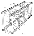
- Figure 1 of the drawings shows an example of a structural member or truss in accordance with the invention. It comprises four elongate elements 10, 11, 12, 13 disposed in spaced generally parallel relationship to one another. In transverse cross-section of the structural member, the elements 10-13 are at the corners of a rectangle, but it will be appreciated that alternative structural members in accordance with the invention may be of different cross-sectional shape, e.g. a polygon such as a square or triangle or indeed some other shape. Other longitudinally extending elements may be provided if required.
- the elements 10-13 are maintained in their spaced generally parallel relationship by a number of a transversely extending elements therebetween.
- Four elements 14, 15, 16, 17 extend perpendicularly to the elements 10-13 along the sides of the rectangle, adjacent the free ends of the elements 10-13.
- a further four such transverse elements 18, 19, 20, 21 extend between the elements 10-13 at a spacing therealong from the end, and further such transverse elements are provided at intervals as required along the length of the structural member.
- a diagonal bracing element 22 extends from the element 13 adjacent the transverse elements 16, 17 to the element 11 adjacent the transverse elements 18, 19.
- a further diagonal bracing element 23 extends from the element 12 adjacent the transverse elements 15, 16 to the element 10 adjacent the transverse elements 18, 21. As illustrated the element 22 is interrupted where it intersects the element 23 and is welded to the latter, but an alternative arrangement could be adopted where the elements cross one another. Further diagonal bracing elements are provided along the length of the truss.
- All the above described elements may be of an aluminium alloy, e.g. extrusions of such a material, and may be secured to one another by welding.
- the members may be of other materials, e.g. steel or possibly even plastics material, may be manufactured by other production processes, e.g. by rolling or pressing from sheet material, and may be secured to one another by other means such as adhesives or fasteners such as rivets or bolts.
- the cross-sectional shape of the elements 10-13 is shown in Figure 2 of the drawings, and is described below.
- the cross-sectional shape of the transverse elements as 14-24 could possibly be the same, or as illustrated may be different and simpler, e.g. circular, square or rectangular, or other convenient shape.
- the cross-sectional shape of the elements 10-13 comprises a hollow generally rectangular box-section portion 28 and a portion 29 which defines an undercut generally T-section track formation 30.
- the portion 29 comprises side wall portions 31, 32 which extend generally parallel to one another from adjacent edges of the portion 28, the wall portions 31, 32 ending at inwardly-facing lip portions 33, 34 which extend towards one another to define an opening 115 therebetween.
- Oppositely outwardly extending recesses 116 are afforded beneath the lip portions 33, 34.
- Lengthwise external ribbing on the elements 10-13 is visible in Figures 2, 4 and 5, but omitted from Figure 6 for clarity. Such external ribbing renders the element easier to grip and handle, to facilitate its use in erection of a structure.
- the track formation 30 provides for engagement with the structural member, at any point along its length, by an attachment member enabling another member, component, or structure to be held to the truss.
- an attachment member may be intended to remain stationary relative to the truss, or may be for connection of a safety line, which is intended to be readily movable lengthwise of the truss so as not to inhibit the movement of a person working in the vicinity thereof.
- Such a movable attachment member may, in its simplest form, be as shown in Figures 3 and 4, being generally T-shaped in end elevation with a head 35 to be engaged with the track formation, extending through the gap between the lip portions 33, 34 and ending in portions which extend outwardly from one another beneath the lip portions.
- a body 36 protrudes from the track formation and is provided with means, e.g. apertures 37, for the connection of a safety line.
- a member as shown in Figures 3 and 4 may be engaged with an element as shown in Figure 2 by sliding the member into the open end of the element and thereafter it may be retained therein by stop means as described hereafter.
- a structural member it would be possible for a structural member to be supplied with a respective slidable member in each of the elongate elements of which it is made, or in only one or some thereof. Whilst it is convenient for the structural member to be made of elongate elements which are the same cross-sectional shape as one another, such that each may be engaged by a fixed or movable attachment member, this need not be the case, only one or some of the elongate elements may be thus shaped. Further, it would be possible for an additional elongate element to be provided in the structural member, having a cross-sectional shape specifically intended to be engaged by a fixed or movable attachment member, e.g. for connection to a safety element.
- FIG. 5 shows two such trusses, indicated generally at 8, 9.
- the truss 9 comprises the four elongate elements 10-13 as above described, whilst the truss 8 comprises corresponding elements 10 a to 13 a .
- Transverse elements extending between the elongate elements of the trusses are shown; in Figure 5 such transverse elements are of different cross-sectional shape and arrangement from those of the truss of Figure 1.
- Connecting means between the elongate elements 11, 11 a is indicated at 26, and the other connecting means between each other pair of corresponding elongate elements is the same.
- the connecting means 26 which connects the adjacent aligned ends of respective elongate elements of the trusses is shown in greater detail in Figures 6 and 7. It comprises two connecting elements which are identical to one another and which face in opposite directions: one of such connecting elements is indicated at 35 in Figures 6 and 7, whilst the other connecting element is shown at 36 in Figure 7.
- the connecting element 35 comprises a spigot 37 which extends as a close fit into the box section portion 28 of the elongate element 23 and is secured therein for example by roll pins extending through apertures 38 in the spigot portion 37 and through aligned apertures drilled in the box-section portion of the elongate element 23.
- the spigot 37 ends in a flange formation 39 which abuts the end face of the elongate element 23 and it will be noted that the flange formation includes a portion 40 which is of similar shape to, and forms a continuation of, the wall portion 32 and lip portion 34 which partially define the track 30 in the elongate element 23.
- the flange formation includes a portion 40 which is of similar shape to, and forms a continuation of, the wall portion 32 and lip portion 34 which partially define the track 30 in the elongate element 23.
- From the flange 39 two spaced parallel limbs 41, 42 extend forwardly, and these limbs are offset from the centre line of the connecting element with the limb 42 having a portion 43 which forms a continuation of the wall portion 31 and lip portion 33 of the elongate element 23 which partially define the track 30 therein.
- the limbs 41, 42 have aligned apertures 44, 45 extending transversely through them.
- the above-described configuration of the connecting element 35 is such that another such connecting element 36 facing in the opposite direction to the connecting element 35 is able to interfit therewith as shown in Figure 3.
- the limbs as 41, 42 of the two connectors intercalate, with the limb (indicated at 41 a in Figure 7) of the connector 36 fitting closely between the limbs 41, 42 of the connector 35.
- the limb 41 of the connecting element 35 fits closely between the limb 41 a of the connecting element 36 and the limb (42 a ) of the latter connector corresponding to the limb 42 of connector 35.
- the apertures as 44, 45 of both the connecting elements are in alignment with one another, enabling the connecting elements to be releasably secured to one another by passing a securing pin, e.g. with a retaining clip, or securing bolt through the aligned apertures.
- a securing pin e.g. with a retaining clip, or securing bolt
- the connecting elements When connected together as above described, the connecting elements further provide a track portion in continuation of the track formations in the elongate elements, enabling an attachment member for a safety line to pass between the track formations of the two elongate elements while remaining captive.
- a worker working thereon and making use of such a safety line does not necessarily have to disconnect the safety line from one truss and reconnect to the other: the attachment member can pass freely between the trusses. Thereby the freedom of working of the worker is not unduly inhibited so he is more likely to make correct use of a safety line.
- the invention enables such an attachment member to be moved freely between trusses prior to being fixed.
- FIG. 8 of the drawings shows a stop member engaged with the connecting element 35.
- the stop member indicated generally at 50, has a fixing portion comprising two spaced parallel limbs 51, 52 which intercalate with the limbs 41, 42 of the connecting element.
- a blocking portion 53 of the stop element blocks the track formation 30 at the end of the elongate element 11, with a portion 54 which engages beneath the portion 43 of the connecting element and a portion 55 which upstands above and blocks the opening 115 which leads into the track formation.
- the portion 53 of the stop member also aligns with the portion 40 of the connecting element and blocks the recess part 116 of the track formation therebeneath.
- the stop member may be secured to the connecting element by a securing pin or bolt passed through aligned apertures at 56 in the stop member and connecting member, in analogous manner to the way above described in which two connecting members are secured together.
- a securing pin or bolt passed through aligned apertures at 56 in the stop member and connecting member, in analogous manner to the way above described in which two connecting members are secured together.
- FIGS 9 and 10 of the drawings show an embodiment of an attachment member intended for movement along the track formation of an elongate element of a truss as above described, while remaining captive thereto for engagement by a safety line. Further, it is able to be engaged with and disengaged from the track formation at a mid-position along the length thereof, not requiring to be engaged or disengaged at an end of the track formation.
- Figure 9 shows an elongate element as one of the elongate elements 10-13 above described, and in Figure 9 this element is indicated at 10. Its shape is as above described, and the track formation afforded thereby is generally T-shaped in cross-section with an opening 115 defined between the inturned lips 33, 34 leading to oppositely outwardly extending recesses 116 beneath the inturned lips.
- An attachment member engageable with the track comprises a body indicated generally at 120.
- the body may be in one piece or, as illustrated, may be of laminated construction comprising a number of body parts indicated at 120 a , 120 b , 120 c disposed upon one another and secured together by any convenient means (not shown).
- Such construction enables the provision of internal cavities in the body for the reception of springs and the like for the purposes described hereafter, and for an attachment ring 121 for connection of a security line to be held captive to the body.
- the part 120 c of the body 120 includes a guide portion 122 which when the attachment member is engaged with the track lies in the opening 115 between the free ends of the lips 114.
- the body may be of metal, e.g. aluminium alloy, or/and may be of a suitable plastics material.
- T-shaped elements Movably mounted relative to the body there are two generally T-shaped elements, one adjacent each end of the body.
- the first of such T-shaped elements comprises a stem 123 which is received in the body for angular movement about its axis 24, and a transverse portion 125 at one end of the stem.
- the angular movement provides for the transverse portion 125 to be moved between the position in which it is shown in Figure 9 in which it lies in alignment with the guide portion 122 and the position in which it is shown in Figure 10 in which it extends transversely outwardly relative to the guide portion 122, to lie within the recesses 16 of the track when the attachment member is engaged with the track.
- Spring biasing means (not shown) preferably biases it to the latter position.
- the stem 123 has secured to it a boss 126 from which an arm 127 extends radially outwardly relative to the axis 124.
- the arm 127 carries a locking member 128 which is spring biased away from the boss 126, the end of the locking member 128 being forked at 129.
- the locking member 128 is only able to move away from the boss 126 when it is facing the opposite end of the body 120 and the transverse portion 125 extends laterally outwardly relative to the guide portion 122.
- the T-shaped element is only able to be moved angularly about the axis 124 after the locking member 128 has been moved towards the boss 126 against the action of its biasing spring.
- the other T-shaped element comprises a stem 132 and a transverse portion 133 at one end thereof.
- the other end of the stem 132 has a head 134 secured thereto, and angular movement of the stem and transverse member 133 about the axis 35 of the stem is prevented from taking place for example by the stem being of non-circular cross-sectional shape (e.g. oval as illustrated), by interengaging formations on the stem and body, or otherwise.
- the T-shaped element is, however, movable lengthwise of the axis of the stem, and is spring biased to the position in which it is shown in Figure 10, with the head 134 spaced from the upper surface of the body 120 of the attachment element and the transverse portion 133 generally in line with the lower surface of the guide portion 122 of the attachment element.
- the T-shaped element is movable to the position shown in Figure 9, in which the transverse portion 133 is clear of the guide portion 122, by pressing on the head 134.
- the attachment member To engage the attachment member with the track at a mid-position of the track, the attachment member is held in the orientation relative to the track in which it is depicted in Figure 9, and the head 134 depressed so that the transverse portion 133 is clear of the guide portion 122.
- This enables the transverse portion to be passed through the opening 115 of the track, after which the attachment member can be moved bodily through about 90° so that the transverse portion 133 extends outwardly in opposite directions into the recesses 116 of the track.
- the guide portion 122 of the attachment member can enter the opening 115, and as it does so the transverse portion 133 is returned, under the influence of its spring biasing, to the position in which it is shown in Figure 10.
- the transverse portion 125 of the other T-shaped element is in alignment with the recesses 116 of the track.
- This T-shaped element can then be moved angularly about the axis 124 of its stem 123 so that the transverse portion 125 enters the recesses 116 of the track, such movement being effected by pressing on the locking member 128 possibly assisted by any spring-biasing means provided in association with this T-shaped element.
- the pin beneath the locking member 128 is able to enter the straight portion 131 of the groove in the upper surface of the body 120 and the locking member 128 move under the action of its biasing spring away from the boss 126 so that its forked end 129 embraces the stem 132 beneath the head 134.
- this position has been assumed, it will be appreciated that the cooperation of the locking member 128 with the stem 134 of the other T-shaped element requires a sequence of operations which is the reverse of the above described sequence to be performed before the attachment member can be disengaged from the track. Such a sequence is most unlikely to be carried out unintentionally.
- Figure 11 shows a first element 150 having upstanding portions 151 with track-engaging formations 152 thereon.
- a further element 153 has upstanding wall portions 154 with track engaging formations 155 thereon. They are shown in full lines in Figure 11 in a position assumed when they are engaged with a track, with the upstanding wall portions 151, 154 in back to back relationship to extend through the opening of a track as previously described, and the formations 152, 155 extending away from one another to enter the recesses beyond the opening of the track.
- the elements 150, 153 are supported by a body of an attachment member in such a way that they are able to move longitudinally of the track relative to one another and also transversely of the track so that they are able to assume an alternative relative position in which the element 150 and its associated parts is shown in broken lines in Figure 11. In this relative position the formations 152, 155 are in alignment with one another in the longitudinal direction so that they can pass through the opening of the track. Then return of the elements 153, 150 to the relative position first described causes the formations 152, 155 to engage the track in such a way that they cannot be removed therefrom.
- end faces of the formations 152, 155 and the associated upstanding walls 151, 154 are shown as inclined cam surfaces which may cooperate in the course of such relative movement of the elements. Any suitable locking means operative between the elements 150, 153 and the body of the attachment member will be provided for ensuring that the condition of secure engagement of the track is retained until disengagement from the track is required.
- FIG. 12 and 13 of the drawings show yet another embodiment which includes a body 160 above which is shown a support member 161.
- the support member 161 carries, for pivotal movement about a spindle 162, two spaced track-engaging elements 163 with respective engaging formations 164.
- the member 161 further carries, for pivotal movement about a spindle (not shown) but whose axis is indicated at 165 parallel to the spindle 162, two spaced track-engaging elements 166 with engaging formation 167.
- the formations 167 face in the opposite direction to the formations 164, transversely of a track part of which is indicated at 168.
- All the elements 163, 166 are pivotably engaged with a further spindle 169 which extends parallel to the aforementioned spindles and is carried by a portion 170 upstanding from the body 160.
- the result of such engagement is that a movement of the body 160 away from the member 161 to the position illustrated in Figure 13 effects a pivotal movement of the elements 163, 166 to a retracted position shown in Figure 13 in which their formations 164, 167 are able to pass through the opening of the track 168.
- some lost motion has to be provided in the connection between the elements 163, 166, 170 and the spindle 169 to accommodate the respective different arcuate paths of movement of the parts of the elements which cooperate with the spindle.
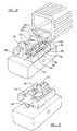
- FIG. 14 of the drawings shows, in a perspective view, an attachment member engageable with the track formation of an elongate element of a truss as above described, intended for the support of some other item, e.g. lighting or sound equipment, relative to the truss. It is intended, when engaged at a required position, to remain in such position.
- some other item e.g. lighting or sound equipment
- the attachment member comprises a body indicated generally at 210 and comprising a circular flange portion 211 whose periphery is knurled to render it easily graspable. Above the flange portion 211 there is a screw-threaded spigot 212 with which there is shown engaged a nut 213 and washer 214, so that the other item or equipment as above referred to may be secured to the attachment member.
- a stem 215 which ends at a transverse portion 216 whose width is slightly less than the opening 115 of the track formation and whose length is sufficient, when the portion 216 is in an appropriate orientation, to extend into the recesses 116 of the track formation.
- the stem 215 receives a collar 218 which is spring biased towards the transverse portion 216 by a compression spring 219. Facing the transverse portion 216, the collar has a dog formation 220 whose width is such as to fit closely in the opening 115 between the inturned lips of the elongate element.
- the attachment element enables it to be held and the transverse portion passed through the opening 115 of the tack formation.
- the collar 218 abuts the elongate element, it can be pressed towards the flange 211 against the force of its biasing spring.
- the attachment member can then be moved through 90° about the longitudinal axis of its body, stem and spigot to orient the transverse portion transversely of the track formation of the elongate element with the ends of the transverse portion lying in the recesses 116 of the track.
- the collar 218, which is not able to move angularly about the axis of the stem, can move towards the transverse portion under the action of the spring so that the dog formation 220 lies between the edges of the inturned lips forming the opening 115.
- the attachment member is then incapable of any further such angular movement, so it remains firmly captive in engagement with the track formation.
- the collar 218 can be manually pulled towards the flange against the action of its biasing spring, and when the dog formation 220 is clear of the opening 115 the attachment member can be moved angularly until the transverse portion can be removed through the opening 115.
- Figure 15 shows diagrammatically how attachment members as shown in Figure 14 may be used to secure another item of equipment to a buss.
- the further item of equipment is a ledge on which a person working at the truss may stand.
- Figure 15 shows two parallel elongate members 230, 231 of a truss, namely the two lower, laterally spaced, elements of an installed truss.
- a sheet-metal, of appropriately pressed section to give it the required strength and rigidity, ledge 232 is connected to two support members 233, 234 which are angle-section pressings or extrusions for example.
- the members 233, 234 are connected to one another by an e.g.
Abstract
Description
- This invention relates to structural members and to parts and fitting used and for use in association therewith.
- Structural members to which the invention relates may be used for the construction of permanent or temporary structures for use in what may broadly be regarded as the entertainment industry. By way of example but not limitation, such structures may be used in association with a stage for the presentation of a musical/theatrical event, for the support of a roof over a stage, for carrying lighting, sound, scenery or other production equipment, or indeed anything that may be required. In many cases such structures are temporary if an event is taking place for a short period of time, but such a structure may well be permanently installed at a location. A further example of a situation in which structural members in accordance with the invention may be utilised is an exhibition stand, but in its broadest aspect structural members in accordance with the invention may be used wherever a requirement arises therefor.
- A basic element from which such structures may be assembled is a "truss", and more particularly a structural member in accordance with the invention may be such a truss. A truss characteristically comprises a number of elongate elements secured in spaced generally parallel relationship to one another by a number of transversely extending elements therebetween. The transversely extending elements are arranged to ensure that the truss is adequately strong and rigid for the loads it is intended to bear: typically some transversely extending elements extend perpendicularly to the elongate elements while other extend diagonally therebetween. Trusses particularly described hereafter are generally rectangular in transverse cross-sectional shape, with principal elongate elements at the comers of the rectangle, but generally trusses may be of other cross-sectional shapes, e.g. polygonal with more or less than four principal elongate elements. For special purposes, some trusses are able to be folded flat to occupy a minimal space for storage or transportation, and erected to an operative cross-sectional shape when required to be used. Generally, there are many known configurations of truss and the invention is applicable throughout the range of such configurations.
- A structure may be created by joining a plurality of trusses together in the required configuration, using suitable connectors and fastenings as described hereafter. A structure may incorporate parts at a substantial height above a floor or ground level, and persons assembling the structure have to work at such heights. After the structure has been completed, further work will be necessary to mount other items such as lighting equipment thereon. Whilst theoretically separate access equipment should be used for safe working at a height, in practice the structure itself may be climbed upon and this brings obvious dangers in case of a fall. With this in view, a person may attach himself to a safety line which is clipped to a truss in the region in which work is taking place, but this inhibits freedom of movement and if a fall occurs may impose loads on the structure which could damage it. Add-on fall-arrest systems have been proposed, but these may interfere with the structure, imposing undue loads thereon, and generally are inconvenient.
- It is broadly the object of one aspect of the present invention to address the above described problem of assisting safety of persons working at a height on a structure as above described.
- According to one aspect of the invention, therefore, we provide a structural member comprising a number of elongate elements disposed in spaced generally parallel relationship to one another with transversely extending elements therebetween, wherein an element extending longitudinally of the structural member is provided with a formation extending lengthwise thereof for engagement by an attachment member to be retained to the longitudinally extending element at any of a range of positions therealong.
- The attachment member may be adapted for connection to a safety element. Then it may be engaged with the formation of the elongate element in such a way as to be freely movable therealong.
- Alternatively the attachment member may provide for the support of lighting or sound equipment for example to the structural member and may be intended, when engaged with the elongate element at a required position, to remain in such position.
- The structural member may be generally of polygonal shape in cross-section, and some or all of the elongate elements may be disposed at the corners of such a polygonal shape. It may be at least one of said elongate elements which is provided with a respective said lengthwise-extending formation. Preferably all of said elongate elements constituting the structural member are of the same cross-sectional shape as one another, and thus each has a said formation.
- The lengthwise-extending formation with which the attachment member is engageable preferably comprises an undercut track formation, shaped so that the attachment member can be held captive in engagement therewith. Preferably the track is generally T-shaped in transverse cross-section, being defined by a base, side walls upstanding therefrom, and inturned lips extending towards one another from the free ends of the side walls. For captive engagement with such a track the attachment member requires to have at least one part or formation which also is generally T-shaped as viewed in cross-section transversely of the track, to extend between the adjacent parts of the inturned lips and outwardly beneath each lip so as to be held captive therein.
- Conveniently each of said elongate elements is an extrusion of an appropriate aluminium alloy. However, other materials may be suitable and it is contemplated that possibly a plastics material, e.g. fibre-reinforced, may be usable. Apart from a portion thereof having the lengthwise extending track formation, the or each elongate element may comprise a portion which is hollow, and which may be of generally square or rectangular transverse cross-sectional shape.
- According to a further aspect of the invention, we provide a structure comprising at least one structural member in accordance with the first aspect of the invention as above set forth. The invention yet further provides such a structure having one or more attachment members engaged with one or more of said track formations thereof. Yet further, a safety device such as a safety lanyard may be connected to at least one of said attachment members.
- Whether an attachment member is intended for connecting something to a track formation as above described at a fixed point along its length, or whether an attachment member for a safety element is movable along the track formation, engagement of such an attachment member with the track has in many cases hitherto required passing thereof lengthwise into the track from an end thereof. Similarly the attachment member has only been able to be disengaged from the track at an end thereof. Whilst this provides a high degree of safety in respect of the security with which the attachment member is held captive when it is in, for example, a mid-position along the track, it would in many cases be convenient if it were to be engageable with and disengageable from the track at such a mid-position. At the same time as providing this convenient ability, however, there should be a high degree of security against an intentional disengagement from the track.
- It is broadly the object of another aspect of the present invention to provide an improved attachment member for such engagement with a track.
- According to another aspect of the invention, therefore, we provide an attachment member for captive engagement with a track formation, the track formation being of undercut configuration in cross-section comprising an opening leading into respective laterally-outwardly-extending recesses at each side; the attachment member comprising a body, means adapted to extend through the opening of the track formation, and formations adapted to extend laterally outwardly generally in opposite directions into said recesses; said formations of the attachment member being movable in respect of their disposition and/or orientation between a first condition wherein they can be passed through said opening into the track and a second condition wherein they extend into said recesses to hold the attachment member in engagement with the track, there being provided locking means for retaining said formations in said second condition.
- Preferably said formations engage each said recess at spaced positions along the track.
- Said formations of the attachment member may be afforded by spaced generally T-shaped elements which have stem portions which, when the attachment member is engaged with the track, extend through the opening of the track, and transverse portions which extend laterally outwardly in opposite directions into said recesses of the track.
- One of said T-shaped elements may be movable angularly about the axis of its stem portion relative to the body of the attachment member, whilst another may be movable lengthwise of its stem portion relative to the body of the attachment member.
- The body of the attachment member may further comprise a guide portion which extends lengthwise of the body, for disposition within the opening of the track. Such guide portion will be generally in alignment with the stem portions of the T-shaped elements. The above described angular movement of one of the T-shaped elements about the axis of its stem portion enables it to be moved to a position in which its transverse portion is generally in alignment with the guide portion, to pass through the opening of the track, whilst a 90° movement of the T-shaped element about the axis of stem portion causes its transverse portion to extend laterally outwardly of the guide portion to enter the recesses of the track.
- However if a guide portion is not provided the attachment member may be guided adequately by the T-shaped elements.
- The T-shaped element which is movable lengthwise of its stem portion may be caused by such movement to assume a position in which its transverse portion is clear of the guide portion of the attachment member, so that with the attachment member as a whole extending transversely of the track the transverse portion of the T-shaped element may be passed through the opening into the track, after which movement of the attachment member through 90° or thereabouts causes the transverse portion of the T-shaped element to extend laterally into the recesses of the track. The guide portion of the attachment member can then be moved into the opening to the track, and the T-shaped element returned, by movement lengthwise of its stem portion to the position in which its transverse portion lies in the vicinity of the guide portion of the attachment member, to hold the attachment member captive to the track. Thereafter the T-shaped element which is movable angularly about the axis of its stem portion can be moved so that its transverse portion also extends into the recesses of the track.
- The attachment member is then guided for movement lengthwise of the track and held captive to the track by its guide portion and by the two transverse portions of the T-shaped elements. If the attachment member were not to be required to be movable lengthwise of the track, the dimensions and/or configuration of its T-shaped elements and/or guide portion may be such that the attachment member is held stationary relative to the track.
- Preferably the T-shaped elements are resiliently biased to the positions they respectively assume when the attachment member is engaged with the track as aforesaid. Suitable springs or other resilient elements may operate on the T-shaped elements in the senses in which they are movable.
- Preferably the locking means cooperates with the T-shaped elements to prevent their respective angular and lengthwise movements about their stem portions. The locking means may comprise a locking member which extends from the stem portion of the angularly moveable T-shaped element and is engageable with the stem portion of the axially movable T-shaped element.
- The locking member may be provided on an arm extending transversely from an end portion of the stem of the angularly movable T-shaped element, the locking member being spring-biased radially away from the stem portion to be engageable with the stem portion of the axially-movable T-shaped element. It may engage beneath a head provided at the end of the stem portion of the axially movable T-shaped element, to prevent such axial movement thereof.
- Yet a further aspect of the invention is concerned with the establishment of a connection, which may be detachable, between two elements disposed in end-to-end relationship with one another, which elements each have a lengthwise extending track formation. The track formation may be engageable, by an attachment member which may be moveable along the track formation in use, for connection to a safety element, as above referred to. Preferably the elongate elements are provided as part of or in association with respective structural truss members as referred to above.
- This farther aspect of the present invention is particularly advantageous in the context of an attachment member for a safety line connection, to enhance the freedom of movement of a person having a safety connection with a structural member in this way by providing for movement of the attachment member from the track formation of one elongate element to the track formation of a further elongate element connected end-to-end therewith, without any requirement for disconnection and re-connection.
- According to a further aspect of the invention, therefore, we provide connecting means for establishing a releasable connection between two elements disposed adjacent one another, each said element being provided with a track formation for engagement by an attachment member, the connecting means affording a track means whereby said attachment member can move between the track formations of said elements whilst remaining captive.
- Preferably the connecting means comprises two connecting elements, each adapted to be secured to one of said elements which are to be connected to one another, and said connecting elements being adapted to be releasably connected to one another and to afford said track means when thus connected.
- Preferably each said connecting element affords a part of said track means. The connecting elements may be identical to one another.
- Preferably each connecting element comprises spaced limbs which, when two connecting elements facing in opposite directions are placed together, intercalate so that holes in the limbs register for the insertion of a fastening element such as a retaining pin or bolt, by which the connecting elements are releasably secured together.
- Each connecting element may comprise a spigot for reception in an opening in one of the elements which are being connected together, whereby the connecting elements are secured to said elements which are to be releasably connected together.
- According to another aspect of the invention, we provide an assembly comprising two elements releasably connected together by connecting means according to the first aspect of the invention.
- Preferably the elements which are releasably connected together are elongate elements, disposed in end to end relationship with one another.
- Preferably the elements which are releasably connected together are elongate elements forming part of respective structural members, each comprising a number of elongate elements disposed in spaced generally parallel relationship with one another, with transversely extending elements therebetween.
- All of the elongate elements in each structural truss may have a track formation as aforesaid, or only some thereof may be thus provided.
- According to another aspect of the invention, we provide a structural member comprising a number of elongate elements disposed in spaced generally parallel relationship to one another with transversely extending elements therebetween, at least one of said elongate elements being provided with a lengthwise-extending track formation for engagement by an attachment member; at least one of said elongate elements with a track formation being provided at its end with a connecting element for releasable connection to a further connecting element provided at the end of a corresponding elongate element of another structural buss disposed in end to end relationship with the first said truss, said connecting elements together defining a track means whereby said attachment member can move between the track formations of the connected elongate elements while remaining captive.
- A connecting element as above set forth may be connectable, as an alternative to being connected to another connecting element, to a stop member which is adapted to block the track formation at the end of the elongate element, to prevent an attachment member engaged with the track formation from becoming disengaged from the track formation by lengthwise movement out of the end thereof.
- The invention fiuther provides, according to another aspect, a stop member engageable with a connecting element as above set forth, the stop member comprising a fixing portion adapted to be secured to the connecting element and a blocking portion adapted to block the track formation adjacent said connecting element.
- The invention also provides, according to another aspect, an attachment member which is intended for connection of equipment or the like to a structural member at a fixed position without being readily movable along the track formation thereof, but which is able to be engaged with the track formation without being passed therealong from an open end.
- The invention yet further provides a structural member having a further member connected thereto by an attachment member as above referred to.
- The invention will now be described by way of example with reference to the accompanying drawings, of which:-
- Figure 1 is a perspective view of part of a structural member in accordance with the invention;
- Figure 2 is a transverse cross-section through one of the elongate elements utilised in the structural member;
- Figures 3 and 4 are respectively an end elevation and side elevation of a member which may be engaged with the elongate element;
- Figure 5 is a perspective view of adjacent parts of two structural trusses connected in accordance with the invention;
- Figure 6 is a perspective view of a connecting element in accordance with the invention;
- Figure 7 is a perspective view illustrating two connecting elements in accordance with the invention, connected together;
- Figure 8 is a perspective view illustrating a stop member connected to a connecting element in accordance with the invention;
- Figure 9 is a perspective view showing an attachment member in accordance with the invention, in a mounting/dismounting condition in relation to an elongate track member;
- Figure 10 is a perspective view showing the condition of the attachment member when engaged with the track member;
- Figure 11 is a perspective view illustrating a further possible arrangement of track-engaging formations of the attachment member;
- Figures 12 and 13 illustrate diagrammatically yet a further possible arrangement of track-engaging formations of the attachment member;
- Figure 14 is a perspective view of an attachment member engageable with a track formation of an elongate element;
- Figure 15 is an underneath view showing how attachment members as Figure 14 can be used to secure a working platform to a structural member.
-
- Referring firstly to Figure 1 of the drawings, this shows an example of a structural member or truss in accordance with the invention. It comprises four
elongate elements - The elements 10-13 are maintained in their spaced generally parallel relationship by a number of a transversely extending elements therebetween. Four
elements transverse elements element 22 extends from theelement 13 adjacent thetransverse elements element 11 adjacent thetransverse elements element 23 extends from theelement 12 adjacent thetransverse elements element 10 adjacent thetransverse elements element 22 is interrupted where it intersects theelement 23 and is welded to the latter, but an alternative arrangement could be adopted where the elements cross one another. Further diagonal bracing elements are provided along the length of the truss. - All the above described elements may be of an aluminium alloy, e.g. extrusions of such a material, and may be secured to one another by welding. However, the members may be of other materials, e.g. steel or possibly even plastics material, may be manufactured by other production processes, e.g. by rolling or pressing from sheet material, and may be secured to one another by other means such as adhesives or fasteners such as rivets or bolts.
- The cross-sectional shape of the elements 10-13 is shown in Figure 2 of the drawings, and is described below. The cross-sectional shape of the transverse elements as 14-24 could possibly be the same, or as illustrated may be different and simpler, e.g. circular, square or rectangular, or other convenient shape.
- The cross-sectional shape of the elements 10-13, clearly seen in Figure 2, comprises a hollow generally rectangular box-
section portion 28 and aportion 29 which defines an undercut generally T-section track formation 30. Theportion 29 comprisesside wall portions portion 28, thewall portions lip portions opening 115 therebetween. Oppositely outwardly extendingrecesses 116 are afforded beneath thelip portions - The
track formation 30 provides for engagement with the structural member, at any point along its length, by an attachment member enabling another member, component, or structure to be held to the truss. Such an attachment member may be intended to remain stationary relative to the truss, or may be for connection of a safety line, which is intended to be readily movable lengthwise of the truss so as not to inhibit the movement of a person working in the vicinity thereof. - Such a movable attachment member may, in its simplest form, be as shown in Figures 3 and 4, being generally T-shaped in end elevation with a
head 35 to be engaged with the track formation, extending through the gap between thelip portions body 36 protrudes from the track formation and is provided with means,e.g. apertures 37, for the connection of a safety line. - A member as shown in Figures 3 and 4 may be engaged with an element as shown in Figure 2 by sliding the member into the open end of the element and thereafter it may be retained therein by stop means as described hereafter. It would be possible for a structural member to be supplied with a respective slidable member in each of the elongate elements of which it is made, or in only one or some thereof. Whilst it is convenient for the structural member to be made of elongate elements which are the same cross-sectional shape as one another, such that each may be engaged by a fixed or movable attachment member, this need not be the case, only one or some of the elongate elements may be thus shaped. Further, it would be possible for an additional elongate element to be provided in the structural member, having a cross-sectional shape specifically intended to be engaged by a fixed or movable attachment member, e.g. for connection to a safety element.
- Referring now to Figures 5, 6 and 7 of the drawings, these show how structural members or trusses as above described may be connected together in end-to-end relationship. Figure 5 shows two such trusses, indicated generally at 8, 9. The truss 9 comprises the four elongate elements 10-13 as above described, whilst the
truss 8 comprises correspondingelements 10a to 13a. Transverse elements extending between the elongate elements of the trusses are shown; in Figure 5 such transverse elements are of different cross-sectional shape and arrangement from those of the truss of Figure 1. Connecting means between theelongate elements 11, 11a is indicated at 26, and the other connecting means between each other pair of corresponding elongate elements is the same. - The connecting means 26 which connects the adjacent aligned ends of respective elongate elements of the trusses is shown in greater detail in Figures 6 and 7. It comprises two connecting elements which are identical to one another and which face in opposite directions: one of such connecting elements is indicated at 35 in Figures 6 and 7, whilst the other connecting element is shown at 36 in Figure 7. The connecting
element 35 comprises aspigot 37 which extends as a close fit into thebox section portion 28 of theelongate element 23 and is secured therein for example by roll pins extending throughapertures 38 in thespigot portion 37 and through aligned apertures drilled in the box-section portion of theelongate element 23. Thespigot 37 ends in aflange formation 39 which abuts the end face of theelongate element 23 and it will be noted that the flange formation includes aportion 40 which is of similar shape to, and forms a continuation of, thewall portion 32 andlip portion 34 which partially define thetrack 30 in theelongate element 23. From theflange 39 two spacedparallel limbs limb 42 having aportion 43 which forms a continuation of thewall portion 31 andlip portion 33 of theelongate element 23 which partially define thetrack 30 therein. Thelimbs apertures - The above-described configuration of the connecting
element 35 is such that another such connectingelement 36 facing in the opposite direction to the connectingelement 35 is able to interfit therewith as shown in Figure 3. The limbs as 41, 42 of the two connectors intercalate, with the limb (indicated at 41a in Figure 7) of theconnector 36 fitting closely between thelimbs connector 35. Similarly thelimb 41 of the connectingelement 35 fits closely between the limb 41a of the connectingelement 36 and the limb (42a) of the latter connector corresponding to thelimb 42 ofconnector 35. When thus fitted together, the apertures as 44, 45 of both the connecting elements are in alignment with one another, enabling the connecting elements to be releasably secured to one another by passing a securing pin, e.g. with a retaining clip, or securing bolt through the aligned apertures. Thus a releasable connection between the elongate elements and the trusses of which they form a part is achieved. - When connected together as above described, the connecting elements further provide a track portion in continuation of the track formations in the elongate elements, enabling an attachment member for a safety line to pass between the track formations of the two elongate elements while remaining captive. Thus when two trusses are connected together, a worker working thereon and making use of such a safety line does not necessarily have to disconnect the safety line from one truss and reconnect to the other: the attachment member can pass freely between the trusses. Thereby the freedom of working of the worker is not unduly inhibited so he is more likely to make correct use of a safety line.
- If instead of a movable attachment member for engagement of a safety line an attachment member intended for fixed mounting of something else to a truss is engaged with the track formation in an elongate element of a truss, the invention enables such an attachment member to be moved freely between trusses prior to being fixed.
- Referring now to Figure 8 of the drawings, this shows a stop member engaged with the connecting
element 35. The stop member, indicated generally at 50, has a fixing portion comprising two spacedparallel limbs limbs portion 53 of the stop element blocks thetrack formation 30 at the end of theelongate element 11, with aportion 54 which engages beneath theportion 43 of the connecting element and aportion 55 which upstands above and blocks theopening 115 which leads into the track formation. Theportion 53 of the stop member also aligns with theportion 40 of the connecting element and blocks therecess part 116 of the track formation therebeneath. - The stop member may be secured to the connecting element by a securing pin or bolt passed through aligned apertures at 56 in the stop member and connecting member, in analogous manner to the way above described in which two connecting members are secured together. When thus fitted to a connecting member, the stop member prevents an attachment member engaged with the
track formation 30 from being disengaged therefrom by lengthwise movement out of the end thereof. - Referring now to Figures 9 and 10 of the drawings, these show an embodiment of an attachment member intended for movement along the track formation of an elongate element of a truss as above described, while remaining captive thereto for engagement by a safety line. Further, it is able to be engaged with and disengaged from the track formation at a mid-position along the length thereof, not requiring to be engaged or disengaged at an end of the track formation.
- Figure 9 shows an elongate element as one of the elongate elements 10-13 above described, and in Figure 9 this element is indicated at 10. Its shape is as above described, and the track formation afforded thereby is generally T-shaped in cross-section with an
opening 115 defined between theinturned lips recesses 116 beneath the inturned lips. - An attachment member engageable with the track comprises a body indicated generally at 120. The body, may be in one piece or, as illustrated, may be of laminated construction comprising a number of body parts indicated at 120a, 120b, 120c disposed upon one another and secured together by any convenient means (not shown). Such construction enables the provision of internal cavities in the body for the reception of springs and the like for the purposes described hereafter, and for an
attachment ring 121 for connection of a security line to be held captive to the body. The part 120c of thebody 120 includes aguide portion 122 which when the attachment member is engaged with the track lies in theopening 115 between the free ends of the lips 114. The body may be of metal, e.g. aluminium alloy, or/and may be of a suitable plastics material. - Movably mounted relative to the body there are two generally T-shaped elements, one adjacent each end of the body. The first of such T-shaped elements comprises a
stem 123 which is received in the body for angular movement about its axis 24, and atransverse portion 125 at one end of the stem. The angular movement provides for thetransverse portion 125 to be moved between the position in which it is shown in Figure 9 in which it lies in alignment with theguide portion 122 and the position in which it is shown in Figure 10 in which it extends transversely outwardly relative to theguide portion 122, to lie within therecesses 16 of the track when the attachment member is engaged with the track. Spring biasing means (not shown) preferably biases it to the latter position. Above thebody 120 thestem 123 has secured to it aboss 126 from which anarm 127 extends radially outwardly relative to theaxis 124. Thearm 127 carries a lockingmember 128 which is spring biased away from theboss 126, the end of the lockingmember 128 being forked at 129. Beneath the lockingmember 128 there is a projection, e.g. a pin (not shown), which engages with a groove in the upper surface of thebody 120, the groove comprising anarcuate portion 130 concentric with theaxis 124 and astraight portion 131 extending therefrom towards the opposite end of thebody 120. This means that the lockingmember 128 is only able to move away from theboss 126 when it is facing the opposite end of thebody 120 and thetransverse portion 125 extends laterally outwardly relative to theguide portion 122. Conversely the T-shaped element is only able to be moved angularly about theaxis 124 after the lockingmember 128 has been moved towards theboss 126 against the action of its biasing spring. - The other T-shaped element comprises a
stem 132 and atransverse portion 133 at one end thereof. The other end of thestem 132 has ahead 134 secured thereto, and angular movement of the stem andtransverse member 133 about theaxis 35 of the stem is prevented from taking place for example by the stem being of non-circular cross-sectional shape (e.g. oval as illustrated), by interengaging formations on the stem and body, or otherwise. The T-shaped element is, however, movable lengthwise of the axis of the stem, and is spring biased to the position in which it is shown in Figure 10, with thehead 134 spaced from the upper surface of thebody 120 of the attachment element and thetransverse portion 133 generally in line with the lower surface of theguide portion 122 of the attachment element. The T-shaped element is movable to the position shown in Figure 9, in which thetransverse portion 133 is clear of theguide portion 122, by pressing on thehead 134. - To engage the attachment member with the track at a mid-position of the track, the attachment member is held in the orientation relative to the track in which it is depicted in Figure 9, and the
head 134 depressed so that thetransverse portion 133 is clear of theguide portion 122. This enables the transverse portion to be passed through theopening 115 of the track, after which the attachment member can be moved bodily through about 90° so that thetransverse portion 133 extends outwardly in opposite directions into therecesses 116 of the track. Theguide portion 122 of the attachment member can enter theopening 115, and as it does so thetransverse portion 133 is returned, under the influence of its spring biasing, to the position in which it is shown in Figure 10. - When the
guide portion 122 of the attachment member lies in theopening 115 of the track, thetransverse portion 125 of the other T-shaped element is in alignment with therecesses 116 of the track. This T-shaped element can then be moved angularly about theaxis 124 of itsstem 123 so that thetransverse portion 125 enters therecesses 116 of the track, such movement being effected by pressing on the lockingmember 128 possibly assisted by any spring-biasing means provided in association with this T-shaped element. When the lockingmember 128 is in the position extending towards the opposite end of thebody 120, corresponding to the disposition of thetransverse portion 125 substantially perpendicular to the length of thebody 120, the pin beneath the lockingmember 128 is able to enter thestraight portion 131 of the groove in the upper surface of thebody 120 and the lockingmember 128 move under the action of its biasing spring away from theboss 126 so that its forkedend 129 embraces thestem 132 beneath thehead 134. When this position has been assumed, it will be appreciated that the cooperation of the lockingmember 128 with thestem 134 of the other T-shaped element requires a sequence of operations which is the reverse of the above described sequence to be performed before the attachment member can be disengaged from the track. Such a sequence is most unlikely to be carried out unintentionally. - Referring now to Figure 11 of the drawings, this illustrates diagrammatically another way in which track-engaging formations of an attachment member can be arranged. Figure 11 shows a
first element 150 havingupstanding portions 151 with track-engagingformations 152 thereon. Afurther element 153 hasupstanding wall portions 154 withtrack engaging formations 155 thereon. They are shown in full lines in Figure 11 in a position assumed when they are engaged with a track, with theupstanding wall portions formations - The
elements element 150 and its associated parts is shown in broken lines in Figure 11. In this relative position theformations elements formations formations upstanding walls elements - Referring now to Figures 12 and 13 of the drawings, these show yet another embodiment which includes a
body 160 above which is shown asupport member 161. Thesupport member 161 carries, for pivotal movement about aspindle 162, two spaced track-engagingelements 163 with respective engagingformations 164. Themember 161 further carries, for pivotal movement about a spindle (not shown) but whose axis is indicated at 165 parallel to thespindle 162, two spaced track-engagingelements 166 with engagingformation 167. Theformations 167 face in the opposite direction to theformations 164, transversely of a track part of which is indicated at 168. - All the
elements further spindle 169 which extends parallel to the aforementioned spindles and is carried by aportion 170 upstanding from thebody 160. The result of such engagement is that a movement of thebody 160 away from themember 161 to the position illustrated in Figure 13 effects a pivotal movement of theelements formations track 168. It will of course be appreciated that some lost motion has to be provided in the connection between theelements spindle 169 to accommodate the respective different arcuate paths of movement of the parts of the elements which cooperate with the spindle. - When in the condition shown in Figure 12 the
formations track 168 to retain the attachment member to the track and guide it for movement there along. Guide formations are shown at 171 on themember 161, for cooperation with the boundaries of the opening of the track. Suitable locking means operative between thebody 160 andmember 161 would be provided for holding them in the position shown in Figure 12, release of such locking means enabling them to be moved to a position shown in Figure 13 for engagement with the track or release therefrom as may be required. - Referring now to Figure 14 of the drawings, this shows, in a perspective view, an attachment member engageable with the track formation of an elongate element of a truss as above described, intended for the support of some other item, e.g. lighting or sound equipment, relative to the truss. It is intended, when engaged at a required position, to remain in such position.
- The attachment member comprises a body indicated generally at 210 and comprising a
circular flange portion 211 whose periphery is knurled to render it easily graspable. Above theflange portion 211 there is a screw-threadedspigot 212 with which there is shown engaged anut 213 andwasher 214, so that the other item or equipment as above referred to may be secured to the attachment member. - On the opposite side of the flange to the spigot, there extends a
stem 215 which ends at atransverse portion 216 whose width is slightly less than theopening 115 of the track formation and whose length is sufficient, when theportion 216 is in an appropriate orientation, to extend into therecesses 116 of the track formation. Between thetransverse portion 216 and the flange, thestem 215 receives acollar 218 which is spring biased towards thetransverse portion 216 by acompression spring 219. Facing thetransverse portion 216, the collar has adog formation 220 whose width is such as to fit closely in theopening 115 between the inturned lips of the elongate element. - The above described construction of the attachment element enables it to be held and the transverse portion passed through the
opening 115 of the tack formation. When thecollar 218 abuts the elongate element, it can be pressed towards theflange 211 against the force of its biasing spring. The attachment member can then be moved through 90° about the longitudinal axis of its body, stem and spigot to orient the transverse portion transversely of the track formation of the elongate element with the ends of the transverse portion lying in therecesses 116 of the track. When suitably oriented, thecollar 218, which is not able to move angularly about the axis of the stem, can move towards the transverse portion under the action of the spring so that thedog formation 220 lies between the edges of the inturned lips forming theopening 115. The attachment member is then incapable of any further such angular movement, so it remains firmly captive in engagement with the track formation. - When the attachment member is required to be disengaged from the track formation, the
collar 218 can be manually pulled towards the flange against the action of its biasing spring, and when thedog formation 220 is clear of theopening 115 the attachment member can be moved angularly until the transverse portion can be removed through theopening 115. - Figure 15 shows diagrammatically how attachment members as shown in Figure 14 may be used to secure another item of equipment to a buss. In this case, the further item of equipment is a ledge on which a person working at the truss may stand. Figure 15 shows two parallel
elongate members ledge 232 is connected to twosupport members members elongate elements points - In the present specification "comprise" means "includes or consists of" and "comprising" means "including or consisting of".
- The features disclosed in the foregoing description, or the following claims, or the accompanying drawings, expressed in their specific forms or in terms of a means for performing the disclosed function, or a method or process for attaining the disclosed result, as appropriate, may, separately, or in any combination of such features, be utilised for realising the invention in diverse forms thereof.
Claims (14)
- A structural member comprising a number of elongate elements (10-13) disposed in spaced generally parallel relationship to one another with transversely extending elements (14-23) therebetween, wherein at least one element (10-13) extending longitudinally of the structural member is provided with a formation (30) extending lengthwise thereof for engagement by an attachment member to be retained to the longitudinally extending element at any of a range of positions therealong.
- A structural member according to Claim 1 which is of polygonal shape in cross-section, and wherein at least some of said elongate elements (10-13) are disposed at corners of said polygonal shape.
- A structural member according to Claim 2 further characterised in that all said elongate elements (10-13) have respective said formations (30).
- A structural member according to any one of the preceding claims further characterised in that said formation (30) comprises an undercut track shaped to hold said attachment member in captive engagement therewith.
- A structural member according to Claim 4 further characterised in that said track formation (30) is generally T-shaped in transverse cross-section.
- A structural member according to any one of the preceding claims further comprising at least one attachment member (Figures 3-4; Figures 9-13; Figure 14) in captive engagement with a said lengthwise extending formation (30) in a longitudinally extending element thereof.
- A structural member according to Claim 6 further characterised in that said attachment member (Figures 3-4; Figures 9-13) is freely movable along said formation (30) in use.
- A structural member according to Claim 7 further characterised in that said formation (30) comprises a track of undercut configuration in transverse cross-section including an opening (115) leading into respective laterally outwardly extending recesses (116) at each side; said at least one attachment member comprising a body (120), means (123, 132) adapted to extend through the opening of the track formation, and formations (125, 133) adapted to extend laterally outwardly generally in opposite directions into said recesses, said formations (125, 133) of the attachment member being movable in respect of at least one of their disposition and orientation between a first condition wherein they can be passed through said opening into the track and a second condition wherein they extend into said recesses to hold the attachment member in engagement with the track, there being locking means (126-131, 134) for retaining said formations in said second condition.
- A structural member according to Claim 8 further characterised in that said formations (125,133) engage each said recess (116) at spaced positions along the track.
- A structural member according to Claim 9 further characterised in that said formations comprise spaced generally T-shaped elements having stem portions (123, 132) which extend through the opening (115) into the track and transverse portions (125, 133) which extend laterally outwardly in opposite directions into said recesses (116) of the track.
- A structural member according to Claim 10 further characterised in that one of said T-shaped elements is movable angularly about the axis of its stem portion (123) relative to the body of the attachment member and one of said T-shaped elements is movable lengthwise of the axis of its stem portion (132) relative to the body of the attachment member
- A structural member according to any one of Claim 8 to 11 wherein the body comprises a guide portion (122) extending lengthwise of the body, for disposition in the opening of the track.
- A structural member according to any one of the preceding claims further characterised in that a said element (10-13) extending longitudinally of the structural member and having a said track formation (30) is provided at its end with a connecting element (35) for releasable connection to a further connecting element (36) provided at the end of a corresponding elongate element (10a-13a) of another structural member disposed in end-to-end relationship with the first said structural member, said connecting elements (35, 36) together defining a connecting track portion whereby an attachment member engaged therewith can move between the track formations of the connected elongate elements while remaining captive.
- A structural member according to Claim 13 further comprising a stop member (50) engaged with said connecting element (35), said stop member including a blocking portion (53) adapted to block the track formation (30) adjacent said connecting element.
Applications Claiming Priority (6)
| Application Number | Priority Date | Filing Date | Title |
|---|---|---|---|
| GB9930628 | 1999-12-24 | ||
| GB9930628A GB2357543B (en) | 1999-12-24 | 1999-12-24 | Structural members |
| GB0022152 | 2000-09-09 | ||
| GB0022154A GB2366591B (en) | 2000-09-09 | 2000-09-09 | Anchor member engageable with a track |
| GB0022152A GB2366590B (en) | 2000-09-09 | 2000-09-09 | Connection between elongate elements |
| GB0022154 | 2000-09-09 |
Publications (3)
| Publication Number | Publication Date |
|---|---|
| EP1111151A2 true EP1111151A2 (en) | 2001-06-27 |
| EP1111151A3 EP1111151A3 (en) | 2002-01-09 |
| EP1111151B1 EP1111151B1 (en) | 2006-09-13 |
Family
ID=27255881
Family Applications (1)
| Application Number | Title | Priority Date | Filing Date |
|---|---|---|---|
| EP00128171A Expired - Lifetime EP1111151B1 (en) | 1999-12-24 | 2000-12-21 | Structural members and associated parts |
Country Status (4)
| Country | Link |
|---|---|
| US (1) | US6408587B2 (en) |
| EP (1) | EP1111151B1 (en) |
| AT (1) | ATE339563T1 (en) |
| DE (1) | DE60030669T2 (en) |
Cited By (6)
| Publication number | Priority date | Publication date | Assignee | Title |
|---|---|---|---|---|
| EP1281820A1 (en) * | 2001-08-03 | 2003-02-05 | Severino Donà | Truss |
| GB2366590B (en) * | 2000-09-09 | 2004-05-12 | Total Fabrications Ltd | Connection between elongate elements |
| WO2014198714A1 (en) * | 2013-06-10 | 2014-12-18 | Sbp Sonne Gmbh | Segmentation of large framework structures |
| WO2014198715A1 (en) * | 2013-06-10 | 2014-12-18 | Sbp Sonne Gmbh | Supporting structure for a parabolic trough collector |
| EP3147424A3 (en) * | 2015-09-24 | 2017-04-05 | Wilhelm Layher Verwaltungs-GmbH | Grid support and grid support system, in particular for universal use within a known work and protection frame |
| CN107088271A (en) * | 2017-04-24 | 2017-08-25 | 武汉轻工大学 | Multifunctional fire-fighting lifesaving appliance |
Families Citing this family (58)
| Publication number | Priority date | Publication date | Assignee | Title |
|---|---|---|---|---|
| US6722471B2 (en) * | 2000-12-22 | 2004-04-20 | Albert A. Wolfe | Scaffolding system having improved safety structures and connecting members |
| US6695877B2 (en) | 2001-02-26 | 2004-02-24 | Scimed Life Systems | Bifurcated stent |
| US7799064B2 (en) | 2001-02-26 | 2010-09-21 | Boston Scientific Scimed, Inc. | Bifurcated stent and delivery system |
| US20030097169A1 (en) * | 2001-02-26 | 2003-05-22 | Brucker Gregory G. | Bifurcated stent and delivery system |
| US6615562B2 (en) * | 2001-09-13 | 2003-09-09 | Skyline Displays, Inc. | Box frame assembly |
| TW593850B (en) * | 2002-10-04 | 2004-06-21 | Lo Mao | Bending moment resistant structure with supporting member and method for the same |
| US20040198141A1 (en) * | 2003-01-24 | 2004-10-07 | Buhrman Gary R. | Children's panel and connector building set |
| US20040187426A1 (en) * | 2003-03-31 | 2004-09-30 | Michael Callahan | Structures and components thereof |
| US20040244327A1 (en) * | 2003-04-25 | 2004-12-09 | William Stonecypher | Trusses |
| US6874971B2 (en) * | 2003-07-08 | 2005-04-05 | Freeman Capital Company | Connector for tube and connected tubular structure |
| DE10351734B3 (en) * | 2003-11-06 | 2005-04-28 | Webasto Ag Fahrzeugtechnik | Guide rail for roof opening system in vehicles has several oblong sections with adapter between each two for a continuous transition between guide paths of rails |
| US7082707B2 (en) * | 2003-11-17 | 2006-08-01 | Valmont Industries, Inc. | Support truss for a messaging sign |
| US7828116B2 (en) * | 2004-05-07 | 2010-11-09 | Jan Vetesnik | Mobile mount for attachment of a fall arrest system |
| US7740106B2 (en) * | 2004-05-10 | 2010-06-22 | Capital Safety Group Winnipeg Ltd. | Mobile mount for attachment of a fall arrest system |
| US20060124698A1 (en) * | 2004-11-29 | 2006-06-15 | Hawthorne Jack W Jr | Device, and associated method, for coupling trusses together |
| WO2006058323A2 (en) * | 2004-11-29 | 2006-06-01 | Hawthorne Jack W Jr | Device, and associated method, for coupling trusses together |
| US7650724B2 (en) * | 2005-03-11 | 2010-01-26 | Hallett Canvas & Sails, Inc. | Tube with external channel |
| BRPI0610803A2 (en) * | 2005-05-13 | 2010-07-27 | Tracy Livingston | structural tower |
| ES2258933B1 (en) * | 2005-07-11 | 2007-07-01 | Sistemas Tecnicos De Encofrados, S.A. | BELT BEAM WITH COUPLABLE TERMINALS. |
| US8435284B2 (en) | 2005-12-14 | 2013-05-07 | Boston Scientific Scimed, Inc. | Telescoping bifurcated stent |
| US8343211B2 (en) | 2005-12-14 | 2013-01-01 | Boston Scientific Scimed, Inc. | Connectors for bifurcated stent |
| CA2530902A1 (en) * | 2005-12-20 | 2007-06-20 | Grant Steel Corp. | Beam-column clamp |
| CA2635656C (en) * | 2005-12-30 | 2014-07-08 | Tracy Livingston | Lifting system and apparatus for constructing wind turbine towers |
| US20120247869A1 (en) * | 2006-02-16 | 2012-10-04 | Anderson Patrick K | Ladder safety apparatus |
| US7654059B2 (en) * | 2006-03-16 | 2010-02-02 | Hejnicki Thomas L | Truss connector |
| US8069634B2 (en) | 2006-10-02 | 2011-12-06 | General Electric Company | Lifting system and apparatus for constructing and enclosing wind turbine towers |
| AU2008232642B2 (en) * | 2007-03-30 | 2014-11-27 | Safway Services, Llc | Erector scaffold deck fall arrest assembly |
| US8051868B2 (en) * | 2008-03-17 | 2011-11-08 | Johnson Outdoors Inc. | Tent rafter end cap and tent incorporating same |
| US8016268B2 (en) * | 2008-05-30 | 2011-09-13 | Wind Tower Systems, Llc | Wind tower service lift |
| MX337407B (en) * | 2008-12-15 | 2016-03-03 | Ge Wind Energy Llc | Structural shape for wind tower members. |
| US8769907B2 (en) * | 2009-07-17 | 2014-07-08 | Bruce E. Camber | Construction elements and method of using and making same |
| ES2776949T3 (en) * | 2009-08-31 | 2020-08-03 | Applied Med Resources | Multifunctional Surgical Access System |
| WO2012082806A2 (en) * | 2010-12-13 | 2012-06-21 | Zep Solar, Inc. | Discrete attachment point apparatus and system for photovoltaic arrays |
| US20130075993A1 (en) * | 2011-09-28 | 2013-03-28 | Christie Lites Enterprises Canada Inc. | Truss and trolley assembly |
| WO2013055814A1 (en) * | 2011-10-14 | 2013-04-18 | Imagine Tf, Llc. | Truss system with integral channels |
| US9698724B2 (en) | 2011-12-13 | 2017-07-04 | Solarcity Corporation | Connecting components for photovoltaic arrays |
| TWI444178B (en) * | 2012-05-21 | 2014-07-11 | Syncmold Entpr Corp | Modular cart |
| USD731678S1 (en) * | 2013-11-21 | 2015-06-09 | Lite Guard Safety Solutions Pty Ltd. | Lifting lug |
| US20150315786A1 (en) | 2014-04-01 | 2015-11-05 | Michael Callahan | Lighting systems and improvements thereto |
| CN104563913B (en) * | 2015-01-12 | 2016-06-08 | 上海振华重工(集团)股份有限公司 | Sleeve pipe stretcher platform framework and external member thereof |
| US20160222625A1 (en) * | 2015-01-30 | 2016-08-04 | Caterpillar Global Mining Llc | Dragline Boom |
| US9650779B2 (en) * | 2015-03-18 | 2017-05-16 | Tyler Truss Systems, Inc. | Adjustable fork connector for connecting trusses |
| US10442503B2 (en) * | 2015-03-27 | 2019-10-15 | Taylor Made Group, Llc | Tubing with internal channel |
| US10214904B2 (en) * | 2016-06-06 | 2019-02-26 | Michael Callahan | Trusses and similar structures |
| US10167634B2 (en) * | 2016-06-10 | 2019-01-01 | Christie Lites Enterprises Canada Inc. | Truss section connection apparatus |
| USD813414S1 (en) * | 2016-06-13 | 2018-03-20 | Nguyen Chi Co., Ltd. | Joint for structural materials |
| JP6871698B2 (en) * | 2016-09-08 | 2021-05-12 | Ntn株式会社 | Water wheel suspension device |
| US9932734B1 (en) | 2016-10-03 | 2018-04-03 | Roger Winter | Deck component with post sleeve and flanges |
| US10174498B2 (en) * | 2016-10-03 | 2019-01-08 | Roger Winter | Deck component with post sleeve and flanges |
| US11052270B2 (en) | 2017-07-24 | 2021-07-06 | Sayfa R&D Pty Ltd | Vertical fall arrest safety device |
| WO2019018888A1 (en) * | 2017-07-24 | 2019-01-31 | Sayfa R&D Pty Ltd | A modular ladder system |
| US10981726B2 (en) | 2017-12-04 | 2021-04-20 | Tiffin Scenic Studios, Inc. | Truss with positioning system |
| US11852419B1 (en) * | 2018-03-29 | 2023-12-26 | Hudson Products Corporation | Air-cooled heat exchanger with tab and slot frame |
| US11660477B2 (en) * | 2018-04-16 | 2023-05-30 | Beacon Roofing Supply, Inc. | Fall protection system |
| CA3004659A1 (en) * | 2018-05-11 | 2019-11-11 | Thomas Chizek | Structural support system |
| CN109736428B (en) * | 2019-01-09 | 2020-02-14 | 燕山大学 | Large-breadth truss rapid butt joint locking mechanism |
| USD947461S1 (en) | 2019-01-30 | 2022-03-29 | Sayfa R&D Pty Ltd | Vertical fall arrest safety device |
| USD1017832S1 (en) * | 2020-07-17 | 2024-03-12 | Global Engineers Investment Singapore Pte. Ltd. | Tower |
Citations (5)
| Publication number | Priority date | Publication date | Assignee | Title |
|---|---|---|---|---|
| US3885647A (en) * | 1973-07-05 | 1975-05-27 | Anthony L Acosta | Climbing safety device |
| FR2330824A1 (en) * | 1975-11-10 | 1977-06-03 | Condevaux Patrick | Built up girder for metal framework - has two parallel flanges interconnected by U-shaped braces screwed to them |
| EP0168021A1 (en) * | 1984-07-13 | 1986-01-15 | Söll Industrieschmiede GmbH | Carriage for a climbing safety device in order to climb a ladder |
| US5156233A (en) * | 1990-07-06 | 1992-10-20 | Machining & Welding By Olsen, Inc. | Safety anchor for use with slotted beams |
| EP0681064A2 (en) * | 1994-05-03 | 1995-11-08 | Bernd Klein | Corner connection for a supporting system |
Family Cites Families (10)
| Publication number | Priority date | Publication date | Assignee | Title |
|---|---|---|---|---|
| US4130177A (en) | 1977-07-15 | 1978-12-19 | Pandolph James E | Ladder climber's safety device |
| US4269284A (en) | 1978-09-25 | 1981-05-26 | Swager William E | Sliding clamp and adaptor |
| GB2070185B (en) | 1980-02-22 | 1983-12-14 | Sykes E C | Scaffold joints supporting flanking bracing |
| CH670394A5 (en) | 1986-09-02 | 1989-06-15 | Bernhard Davatz | |
| GB8829415D0 (en) | 1988-12-15 | 1989-02-01 | Queen William G | Safety retaining device for work personnel |
| EP0593150B1 (en) | 1992-07-02 | 1996-12-04 | David S. Gleave | Safety device |
| FI116512B (en) | 1992-08-19 | 2005-12-15 | Jita Pipe Oy | Lockable carriage |
| GB2278627B (en) | 1993-05-28 | 1996-05-15 | Unistrut | Safety tethering system |
| GB9317280D0 (en) * | 1993-08-19 | 1993-10-06 | James Thomas Engineering Limit | Structural truss |
| DE19755828C2 (en) * | 1997-12-17 | 2000-10-12 | Cedargrove Ltd | Device for connecting curtain rails for curtain gliders |
-
2000
- 2000-12-21 US US09/746,586 patent/US6408587B2/en not_active Expired - Fee Related
- 2000-12-21 EP EP00128171A patent/EP1111151B1/en not_active Expired - Lifetime
- 2000-12-21 AT AT00128171T patent/ATE339563T1/en not_active IP Right Cessation
- 2000-12-21 DE DE60030669T patent/DE60030669T2/en not_active Expired - Fee Related
Patent Citations (5)
| Publication number | Priority date | Publication date | Assignee | Title |
|---|---|---|---|---|
| US3885647A (en) * | 1973-07-05 | 1975-05-27 | Anthony L Acosta | Climbing safety device |
| FR2330824A1 (en) * | 1975-11-10 | 1977-06-03 | Condevaux Patrick | Built up girder for metal framework - has two parallel flanges interconnected by U-shaped braces screwed to them |
| EP0168021A1 (en) * | 1984-07-13 | 1986-01-15 | Söll Industrieschmiede GmbH | Carriage for a climbing safety device in order to climb a ladder |
| US5156233A (en) * | 1990-07-06 | 1992-10-20 | Machining & Welding By Olsen, Inc. | Safety anchor for use with slotted beams |
| EP0681064A2 (en) * | 1994-05-03 | 1995-11-08 | Bernd Klein | Corner connection for a supporting system |
Cited By (7)
| Publication number | Priority date | Publication date | Assignee | Title |
|---|---|---|---|---|
| GB2366590B (en) * | 2000-09-09 | 2004-05-12 | Total Fabrications Ltd | Connection between elongate elements |
| EP1281820A1 (en) * | 2001-08-03 | 2003-02-05 | Severino Donà | Truss |
| WO2014198714A1 (en) * | 2013-06-10 | 2014-12-18 | Sbp Sonne Gmbh | Segmentation of large framework structures |
| WO2014198715A1 (en) * | 2013-06-10 | 2014-12-18 | Sbp Sonne Gmbh | Supporting structure for a parabolic trough collector |
| EP3147424A3 (en) * | 2015-09-24 | 2017-04-05 | Wilhelm Layher Verwaltungs-GmbH | Grid support and grid support system, in particular for universal use within a known work and protection frame |
| CN107088271A (en) * | 2017-04-24 | 2017-08-25 | 武汉轻工大学 | Multifunctional fire-fighting lifesaving appliance |
| CN107088271B (en) * | 2017-04-24 | 2020-06-23 | 武汉轻工大学 | Multifunctional fire-fighting life-saving device |
Also Published As
| Publication number | Publication date |
|---|---|
| US6408587B2 (en) | 2002-06-25 |
| DE60030669D1 (en) | 2006-10-26 |
| EP1111151A3 (en) | 2002-01-09 |
| ATE339563T1 (en) | 2006-10-15 |
| EP1111151B1 (en) | 2006-09-13 |
| DE60030669T2 (en) | 2007-09-13 |
| US20010004823A1 (en) | 2001-06-28 |
Similar Documents
| Publication | Publication Date | Title |
|---|---|---|
| EP1111151B1 (en) | Structural members and associated parts | |
| US5156233A (en) | Safety anchor for use with slotted beams | |
| US20180313107A1 (en) | Methods of supporting upright items from a support surface | |
| US20040035993A1 (en) | Roof anchors | |
| CN101680231B (en) | Erector scaffold deck fall arrest assembly | |
| CA2433160C (en) | Quick connect/disconnect fall arrest anchorage with permanent connectors | |
| US20040055233A1 (en) | Anchor attachment for a roof panel rib | |
| CZ163795A3 (en) | Corner joint | |
| EP3441543A1 (en) | Improvements relating to lifting of building units | |
| US6887022B2 (en) | Quick connect/disconnect fall arrest anchorage | |
| US7452153B2 (en) | Fitting for joining scaffold boards | |
| US20070235257A1 (en) | Ladder support and lift system | |
| EP1050687B1 (en) | Safety line anchorage assemblies | |
| JP2002174027A (en) | Scaffolding-board gap cover | |
| GB2376729A (en) | Structural assembly | |
| JP3005277U (en) | Safety enclosure for lifting ladders | |
| KR101040651B1 (en) | Scaffolding clamp and scaffolding clamp assembly using the same | |
| KR200164131Y1 (en) | Multipurpose clamp for scaffold | |
| JPH0754463Y2 (en) | Connecting device for building frame used for temporary scaffolding | |
| WO1995006179A1 (en) | Safety railing system | |
| GB2357543A (en) | Structural members with provision for attachment to a safety device | |
| WO2005038168A1 (en) | Connecting shuttle | |
| JPH09328904A (en) | Safety handrail for frame block | |
| GB2366591A (en) | Anchor member for engaging track in safety line system | |
| JPH0673244U (en) | Mounting structure for scaffolding on pillar |
Legal Events
| Date | Code | Title | Description |
|---|---|---|---|
| PUAI | Public reference made under article 153(3) epc to a published international application that has entered the european phase |
Free format text: ORIGINAL CODE: 0009012 |
|
| AK | Designated contracting states |
Kind code of ref document: A2 Designated state(s): AT BE CH CY DE DK ES FI FR GB GR IE IT LI LU MC NL PT SE TR |
|
| AX | Request for extension of the european patent |
Free format text: AL;LT;LV;MK;RO;SI |
|
| RIC1 | Information provided on ipc code assigned before grant |
Free format text: 7E 04C 3/08 A, 7E 04C 3/04 B, 7A 62B 1/04 B |
|
| PUAL | Search report despatched |
Free format text: ORIGINAL CODE: 0009013 |
|
| AK | Designated contracting states |
Kind code of ref document: A3 Designated state(s): AT BE CH CY DE DK ES FI FR GB GR IE IT LI LU MC NL PT SE TR |
|
| AX | Request for extension of the european patent |
Free format text: AL;LT;LV;MK;RO;SI |
|
| 17P | Request for examination filed |
Effective date: 20020709 |
|
| AKX | Designation fees paid |
Free format text: AT BE CH CY DE DK ES FI FR GB GR IE IT LI LU MC NL PT SE TR |
|
| 17Q | First examination report despatched |
Effective date: 20031103 |
|
| GRAP | Despatch of communication of intention to grant a patent |
Free format text: ORIGINAL CODE: EPIDOSNIGR1 |
|
| GRAS | Grant fee paid |
Free format text: ORIGINAL CODE: EPIDOSNIGR3 |
|
| RAP1 | Party data changed (applicant data changed or rights of an application transferred) |
Owner name: T2 SYSTEMS LIMITED |
|
| GRAA | (expected) grant |
Free format text: ORIGINAL CODE: 0009210 |
|
| AK | Designated contracting states |
Kind code of ref document: B1 Designated state(s): AT BE CH CY DE DK ES FI FR GR IE IT LI LU MC NL PT SE TR |
|
| PG25 | Lapsed in a contracting state [announced via postgrant information from national office to epo] |
Ref country code: IT Free format text: LAPSE BECAUSE OF FAILURE TO SUBMIT A TRANSLATION OF THE DESCRIPTION OR TO PAY THE FEE WITHIN THE PRESCRIBED TIME-LIMIT;WARNING: LAPSES OF ITALIAN PATENTS WITH EFFECTIVE DATE BEFORE 2007 MAY HAVE OCCURRED AT ANY TIME BEFORE 2007. THE CORRECT EFFECTIVE DATE MAY BE DIFFERENT FROM THE ONE RECORDED. Effective date: 20060913 Ref country code: LI Free format text: LAPSE BECAUSE OF FAILURE TO SUBMIT A TRANSLATION OF THE DESCRIPTION OR TO PAY THE FEE WITHIN THE PRESCRIBED TIME-LIMIT Effective date: 20060913 Ref country code: AT Free format text: LAPSE BECAUSE OF FAILURE TO SUBMIT A TRANSLATION OF THE DESCRIPTION OR TO PAY THE FEE WITHIN THE PRESCRIBED TIME-LIMIT Effective date: 20060913 Ref country code: FI Free format text: LAPSE BECAUSE OF FAILURE TO SUBMIT A TRANSLATION OF THE DESCRIPTION OR TO PAY THE FEE WITHIN THE PRESCRIBED TIME-LIMIT Effective date: 20060913 Ref country code: CH Free format text: LAPSE BECAUSE OF FAILURE TO SUBMIT A TRANSLATION OF THE DESCRIPTION OR TO PAY THE FEE WITHIN THE PRESCRIBED TIME-LIMIT Effective date: 20060913 Ref country code: BE Free format text: LAPSE BECAUSE OF FAILURE TO SUBMIT A TRANSLATION OF THE DESCRIPTION OR TO PAY THE FEE WITHIN THE PRESCRIBED TIME-LIMIT Effective date: 20060913 |
|
| REG | Reference to a national code |
Ref country code: CH Ref legal event code: EP |
|
| REG | Reference to a national code |
Ref country code: IE Ref legal event code: FG4D |
|
| REF | Corresponds to: |
Ref document number: 60030669 Country of ref document: DE Date of ref document: 20061026 Kind code of ref document: P |
|
| PG25 | Lapsed in a contracting state [announced via postgrant information from national office to epo] |
Ref country code: SE Free format text: LAPSE BECAUSE OF FAILURE TO SUBMIT A TRANSLATION OF THE DESCRIPTION OR TO PAY THE FEE WITHIN THE PRESCRIBED TIME-LIMIT Effective date: 20061213 Ref country code: DK Free format text: LAPSE BECAUSE OF FAILURE TO SUBMIT A TRANSLATION OF THE DESCRIPTION OR TO PAY THE FEE WITHIN THE PRESCRIBED TIME-LIMIT Effective date: 20061213 |
|
| PG25 | Lapsed in a contracting state [announced via postgrant information from national office to epo] |
Ref country code: ES Free format text: LAPSE BECAUSE OF FAILURE TO SUBMIT A TRANSLATION OF THE DESCRIPTION OR TO PAY THE FEE WITHIN THE PRESCRIBED TIME-LIMIT Effective date: 20061224 |
|
| PG25 | Lapsed in a contracting state [announced via postgrant information from national office to epo] |
Ref country code: MC Free format text: LAPSE BECAUSE OF NON-PAYMENT OF DUE FEES Effective date: 20061231 |
|
| PG25 | Lapsed in a contracting state [announced via postgrant information from national office to epo] |
Ref country code: PT Free format text: LAPSE BECAUSE OF FAILURE TO SUBMIT A TRANSLATION OF THE DESCRIPTION OR TO PAY THE FEE WITHIN THE PRESCRIBED TIME-LIMIT Effective date: 20070302 |
|
| REG | Reference to a national code |
Ref country code: CH Ref legal event code: PL |
|
| EN | Fr: translation not filed | ||
| PLBE | No opposition filed within time limit |
Free format text: ORIGINAL CODE: 0009261 |
|
| STAA | Information on the status of an ep patent application or granted ep patent |
Free format text: STATUS: NO OPPOSITION FILED WITHIN TIME LIMIT |
|
| 26N | No opposition filed |
Effective date: 20070614 |
|
| PG25 | Lapsed in a contracting state [announced via postgrant information from national office to epo] |
Ref country code: FR Free format text: LAPSE BECAUSE OF FAILURE TO SUBMIT A TRANSLATION OF THE DESCRIPTION OR TO PAY THE FEE WITHIN THE PRESCRIBED TIME-LIMIT Effective date: 20070518 Ref country code: GR Free format text: LAPSE BECAUSE OF FAILURE TO SUBMIT A TRANSLATION OF THE DESCRIPTION OR TO PAY THE FEE WITHIN THE PRESCRIBED TIME-LIMIT Effective date: 20061214 |
|
| PGFP | Annual fee paid to national office [announced via postgrant information from national office to epo] |
Ref country code: IE Payment date: 20080307 Year of fee payment: 8 |
|
| PG25 | Lapsed in a contracting state [announced via postgrant information from national office to epo] |
Ref country code: TR Free format text: LAPSE BECAUSE OF FAILURE TO SUBMIT A TRANSLATION OF THE DESCRIPTION OR TO PAY THE FEE WITHIN THE PRESCRIBED TIME-LIMIT Effective date: 20060913 Ref country code: LU Free format text: LAPSE BECAUSE OF NON-PAYMENT OF DUE FEES Effective date: 20061221 |
|
| PG25 | Lapsed in a contracting state [announced via postgrant information from national office to epo] |
Ref country code: FR Free format text: LAPSE BECAUSE OF FAILURE TO SUBMIT A TRANSLATION OF THE DESCRIPTION OR TO PAY THE FEE WITHIN THE PRESCRIBED TIME-LIMIT Effective date: 20060913 Ref country code: CY Free format text: LAPSE BECAUSE OF FAILURE TO SUBMIT A TRANSLATION OF THE DESCRIPTION OR TO PAY THE FEE WITHIN THE PRESCRIBED TIME-LIMIT Effective date: 20060913 |
|
| PGFP | Annual fee paid to national office [announced via postgrant information from national office to epo] |
Ref country code: NL Payment date: 20081203 Year of fee payment: 9 |
|
| PGFP | Annual fee paid to national office [announced via postgrant information from national office to epo] |
Ref country code: DE Payment date: 20081219 Year of fee payment: 9 |
|
| PG25 | Lapsed in a contracting state [announced via postgrant information from national office to epo] |
Ref country code: IE Free format text: LAPSE BECAUSE OF NON-PAYMENT OF DUE FEES Effective date: 20081222 |
|
| REG | Reference to a national code |
Ref country code: NL Ref legal event code: V1 Effective date: 20100701 |
|
| PG25 | Lapsed in a contracting state [announced via postgrant information from national office to epo] |
Ref country code: NL Free format text: LAPSE BECAUSE OF NON-PAYMENT OF DUE FEES Effective date: 20100701 |
|
| PG25 | Lapsed in a contracting state [announced via postgrant information from national office to epo] |
Ref country code: DE Free format text: LAPSE BECAUSE OF NON-PAYMENT OF DUE FEES Effective date: 20100701 |