EP1112818A2 - An apparatus for applying a controlled amount of torque - Google Patents
An apparatus for applying a controlled amount of torque Download PDFInfo
- Publication number
- EP1112818A2 EP1112818A2 EP00127920A EP00127920A EP1112818A2 EP 1112818 A2 EP1112818 A2 EP 1112818A2 EP 00127920 A EP00127920 A EP 00127920A EP 00127920 A EP00127920 A EP 00127920A EP 1112818 A2 EP1112818 A2 EP 1112818A2
- Authority
- EP
- European Patent Office
- Prior art keywords
- torque
- leaf spring
- rotor
- head
- cavity
- Prior art date
- Legal status (The legal status is an assumption and is not a legal conclusion. Google has not performed a legal analysis and makes no representation as to the accuracy of the status listed.)
- Granted
Links
- 230000002708 enhancing effect Effects 0.000 claims description 5
- 230000000717 retained effect Effects 0.000 claims description 2
- 230000007246 mechanism Effects 0.000 abstract description 15
- 238000009434 installation Methods 0.000 abstract description 7
- 230000001954 sterilising effect Effects 0.000 abstract description 5
- 238000004659 sterilization and disinfection Methods 0.000 abstract description 5
- 235000000621 Bidens tripartita Nutrition 0.000 description 7
- 240000004082 Bidens tripartita Species 0.000 description 7
- 208000006637 fused teeth Diseases 0.000 description 7
- 229910052751 metal Inorganic materials 0.000 description 6
- 239000002184 metal Substances 0.000 description 6
- 239000000463 material Substances 0.000 description 5
- 238000000034 method Methods 0.000 description 5
- 230000008901 benefit Effects 0.000 description 3
- 238000001816 cooling Methods 0.000 description 2
- 238000012986 modification Methods 0.000 description 2
- 230000004048 modification Effects 0.000 description 2
- 230000008569 process Effects 0.000 description 2
- RTAQQCXQSZGOHL-UHFFFAOYSA-N Titanium Chemical compound [Ti] RTAQQCXQSZGOHL-UHFFFAOYSA-N 0.000 description 1
- 238000013459 approach Methods 0.000 description 1
- 238000005452 bending Methods 0.000 description 1
- 230000006835 compression Effects 0.000 description 1
- 238000007906 compression Methods 0.000 description 1
- 238000010276 construction Methods 0.000 description 1
- 238000005516 engineering process Methods 0.000 description 1
- 239000003292 glue Substances 0.000 description 1
- 230000014759 maintenance of location Effects 0.000 description 1
- 238000005096 rolling process Methods 0.000 description 1
- 230000035939 shock Effects 0.000 description 1
- 229910001220 stainless steel Inorganic materials 0.000 description 1
- 239000010935 stainless steel Substances 0.000 description 1
- 239000010936 titanium Substances 0.000 description 1
- 229910052719 titanium Inorganic materials 0.000 description 1
- 238000003466 welding Methods 0.000 description 1
Images


Classifications
-
- B—PERFORMING OPERATIONS; TRANSPORTING
- B25—HAND TOOLS; PORTABLE POWER-DRIVEN TOOLS; MANIPULATORS
- B25B—TOOLS OR BENCH DEVICES NOT OTHERWISE PROVIDED FOR, FOR FASTENING, CONNECTING, DISENGAGING OR HOLDING
- B25B23/00—Details of, or accessories for, spanners, wrenches, screwdrivers
- B25B23/14—Arrangement of torque limiters or torque indicators in wrenches or screwdrivers
- B25B23/142—Arrangement of torque limiters or torque indicators in wrenches or screwdrivers specially adapted for hand operated wrenches or screwdrivers
- B25B23/1422—Arrangement of torque limiters or torque indicators in wrenches or screwdrivers specially adapted for hand operated wrenches or screwdrivers torque indicators or adjustable torque limiters
- B25B23/1427—Arrangement of torque limiters or torque indicators in wrenches or screwdrivers specially adapted for hand operated wrenches or screwdrivers torque indicators or adjustable torque limiters by mechanical means
Definitions
- the present disclosure relates to controlling the amount of torque applied to a threaded connection. More particularly, the present disclosure relates to an apparatus for applying a controlled amount of torque to either install or remove a threaded connection working member.
- Torque wrenches are well known devices which most commonly use one or more elastic bending rods as in U.S. Patent No. 5,734,113 to Vogt et al. ("Vogt et al.") or an axial spring device as in U.S. Patent No. 5,859,371 to Hsieh (“Hsieh”) and U.S. Patent No. 5,911,801 to Fravalo et al. (“Fravalo et al.”) as the primary source of their torque sensing mechanism.
- These torque wrenches use complex mechanisms that frequently employ one or more helical springs, roller bearings, and rod devices enclosed within their handle cavity.
- Fravalo teaches a wrench head that pivots inside a hollow cavity and interfaces with a plunger rod type device that employs at least one rolling body to minimize friction. This mechanism then interfaces with an axially coiled spring. These internal mechanisms are too complex to support disassembly for ease of sterilization and are too expensive to use as a disposable torque wrench device.
- Rueb teaches two basic embodiments of cantilevered beam leaf spring type torque wrench mechanisms that slip when the torque limit is exceeded.
- the leaf spring acts as a cantilever beam that extends from the handle to perpendicularly engage a single symmetrical vertical gear tooth in the wrench head. Torque values are adjusted on the handle by varying the effective length of the cantilevered beam.
- Rueb discloses two perpendicular springs located within the wrench head that engage gear teeth a with complex double tooth shape. The perpendicular springs that engage the complex double tooth gears are held in place by two retaining shoulders of different height that create a shorter stiffer beam with greater resistive force in the counterclockwise direction than in the clockwise direction.
- Each complex double tooth of the gear has a single tooth side, where only the long tooth is engaged, and a double tooth side, where first the short and then the long tooth is engaged.
- the single tooth and double tooth sides are symmetrically sloped.
- Maximum clockwise torque is achieved as the longer tooth is engaged on the single tooth side of the complex double tooth gear by the perpendicular leaf spring and the perpendicular leaf spring is forced past the resisting counter force of the spring retaining shoulder.
- the lower clockwise supporting spring retaining shoulder creates a cantilever beam with a longer, less resistive counter force.
- This second embodiment removes a threaded member in the counterclockwise direction without adjustments using a combination of the double tooth form and the shock force imparted by the spring as it forced past the first shorter tooth and then impacts upon the second longer tooth.
- the longer counterclockwise retaining shoulder support provides a shorter cantilevered spring that provides greater resistive force than in the clockwise direction.
- the second embodiment of Reub is distinctly limited by its lack of ability to adjust for different torque values and its internal complexity which precludes it from being disassembled, sterilized, and reassembled for use in a sterile environment.
- this and other current torque wrench designs require the surgical instrument to be removed from the sterile environment, their working member removed and replaced with the proper torque, and then the surgical instrument must be resterilized.
- Torque wrenches that have mechanisms such as those above and are used in medical applications are typically not used in a sterile environment.
- the apparatus be simple in construction, easy to disassemble and reassemble, and that it does not require calibration upon reassembly. It is desirable to provide a torquing apparatus that is so inexpensive that it can be disposable. It is further desirable that the torquing apparatus have the potential to apply different torques for different threaded member applications and require no adjustments for the installation or removal of a specific threaded connection.
- a torque apparatus employs a plurality of leaf spring elements engaging a plurality of asymmetrical drive teeth sides to establish a range of preset torque values for the installation and removal of threaded connecting devices.
- the preset torque values can be readily changed by employing different quantities of leaf springs, differing leaf spring designs, or varying the geometry of the rotor drive teeth.
- the leaf spring to rotor drive teeth interface provides a slip mechanism to prevent over-torquing when torque values for either the installation or removal of a threaded connecting type device are exceeded.
- the wrench head may be hermetically sealed in its preferred configuration, or in an alternative configuration capable of full disassembly. Both configurations can be readily sterilized using an autoclave or similar sterilization methods.
- the second configuration adds the advantage that the apparatus can be reconfigured for different torque applications without calibration within a sterilized environment.
- the wrench can also be employed as a disposable device.
- torque wrench 100 includes a handle 110, a head 112, at least one leaf spring 120, at least one rotor 130, a plurality of hex inserts 140, and a cap 150.
- cap 150 When cap 150 is in position, it holds rotor 130 and hex insert 140 in place within head 112.
- Cap 150 can be fixedly connected to head 112 using ultrasonic welding, or similar techniques, to form a hermitic seal, removably attached, or be an integral part of head 112.
- torque wrench 100 is configured to be easily sterilized as a hermitically sealed assembly or disassembled and sterilized using widely available sterilization techniques.
- Torque wrench 100 is configurable as either a disposable or reusable instrument.
- torque wrench 100 has a handle 110 on a first end, and a head 112 on an opposing second end.
- Handle 110 contains a grip enhancing means 111 that includes ergonomic enhancements such as knurling, scalloping, or undulations that aid gripping.
- Head 112 has side walls 113 that define internal cavity 114. Internal cavity 114 in head 112 has a hexagonal shape in this configuration with two stops 116 on the inside of side walls 113.
- Handle 110 and head 112 are preferably made of plastic although other medical grade materials are also envisaged such as, e.g. stainless steel, titanium, etc.
- cap 150 contains a grip enhancing means 111, such as knurling, scalloping, or radially extending undulations, and would enable the user to apply sufficient torque in the lower ranges of torque values.
- grip enhancing means 111 such as knurling, scalloping, or radially extending undulations
- FIG. 2C an additional configuration is shown which integrates handle 110 into head 112.
- head 112 contains a grip enhancing means 111, such as knurling, scalloping, or radially extending undulations, and would similarly enable the user to apply sufficient torque in the lower ranges of torque values.
- This configuration of torque apparatus 100 could also be extended longitudinally to take the form of a screwdriver-torque wrench.
- angular leaf spring 120 has a plurality of novel cantilevered beam elements 122 that are sharply angled from a radial azimuth and are positioned to provide the torque limiting component of the design.
- Each beam element 122 has a first section 124 and a second section 126, which is defined by a second bend in the beam element 122.
- Second bend section 126 facilitates sustaining the proper degree of physical interface at all times.
- Second section 126 has end with an inside end corner 128 that is coined with a radius profile that is designed to minimize frictional forces.
- leaf spring 120 is shown with angled cantilevered beam elements 122.
- the number of leaf spring elements 122 per leaf spring 120 can vary with the design application.
- Leaf spring 120 is preferably made from a sheet metal stamping.
- the rotor 130 in this configuration has twelve simple radially extending single toothed drive teeth 131.
- the quantity of drive teeth 131 can vary with the design application.
- Each drive teeth 131 has a clockwise ramp side 132 and a counterclockwise flat side 134.
- the top of rotor 130 defines a hexagonal cavity 136 with sidewalls 138.
- Rotor 130 is preferably made of medical grade plastic materials.
- FIG. 4B the asymmetrical nature of the sides of drive teeth 131 of rotor 130 is illustrated.
- clockwise ramp sides 132 are gradually sloped and counterclockwise flat sides 134 are steeply angled. Additional asymmetrical configurations of sides 132 and 134 can be used to vary the range of torque values of this mechanism.
- the rotor 130 design can be reversed to have a flat side 134 in the clockwise direction and a ramp side 132 in the counterclockwise direction.
- drive insert 140 functions as a drive mechanism interface for threaded connecting devices.
- a 9/32 inch hex drive insert 140 is shown that is specifically intended to interface with the CUSA EXcel 23 kHz product manufactured by Valleylab Inc.
- the drive insert 140 hex interface can also be configured for a 7/32 inch hex drive 140 to interface with CUSA EXcel 36 kHz handpieces manufactured by Valleylab Inc.
- Additional drive insert 140 configurations could include interfaces for other hexagonal sizes as well as hex key, slot or phillips head screw driver, or any similar working member or attachment type device.
- All the drive inserts 140 such as the 7/32 drive insert 140 and 9/32 insert have the same external hexagonal sidewall 144 dimensions and shoulder 146 and are thus interchangeable.
- Drive insert 140 is preferably made of metal, and in the removable cap configuration, is specifically designed to be easily changed in a sterile environment.
- torque wrench 100 is shown partially assembled.
- two leaf springs 120 are installed in head 112 between two stops 116 in cavity 114.
- Torque wrench 100 can operate with one or more leaf springs 120 to establish a different set of torque values at preset intervals. Torque values are preset in the hermetically sealed configuration and, in addition, torque wrench 100 can also be configured to be easily disassembled in so that leaf springs 120 may be easily added to or removed from head 112 in a sterile environment.
- Rotor 130 is positioned within head 112 to engage leaf spring elements 122.
- Hex drive insert 140 can be a separate assembly and installed within rotor 130 or be configured as an integral part of the rotor 130.
- the drive insert 140 As installed within rotor 130 as a separate assembly, the drive insert 140 is inserted into hexagonal cavity 136. Sidewalls 144 of rotor 140 then interface directly with the sidewalls 138 of hexagonal cavity 136.
- the materials in the combined configuration of rotor 130 and drive insert 140 can include medical grade plastic or metal for both subassemblies or combinations of different materials bonded together.
- Drive insert 140 has a shoulder 146 which rides between the head 112 and the rotor 130.
- the drive insert 140 is designed to be removable and replaceable in a sterile environment and is retained inside rotor 130 without a press fit or glue.
- each leaf spring element 122 turns rotor drive teeth 131, drive insert 140, and thus the threaded connecting device with the user's applied torque until the torque limit is exceeded.
- ramp sides 132 engage a plurality of inside coined edges 128 of second sections 126 of beam elements 122.
- the coining of inside edge 128 creates an almost frictionless interface between the plastic rotor 130 and metal beam element 122. With friction reduced, the user then only needs to increase the applied torque to ramp side 132 to deflect and overcome the opposing counter force from the spring bias of the at least one angled leaf spring cantilever beam element 122.
- each cantilevered beam element 122 increases as it is deflected and applied clockwise torque approaches its maximum as the inside edge tip 128 of second section 126 is forced up ramp side 132.
- the applied torque peaks just prior to leaf spring element 122 releasing past ramp side 132.
- the slippage of each leaf spring element 122 up and over ramp side 132 of rotor drive teeth 131 defines a torque controlling mechanism that limits the applied torque to rotor drive teeth 131 and drive insert 140.
- torque wrench 100 achieves approximately 30 in-lbs in the clockwise direction before releasing for the CUSA EXcel 36 kHz instrument and, using two leaf springs, at least about 60 in-lbs for the CUSA EXcel 23 kHz instrument before leasing.
- a plurality of flat sides 134 of rotor 130 form flush interfaces with a plurality of second beam sections 126 of cantilevered beam elements 122.
- beam elements 122 are placed primarily in compression and secondarily in a transverse deflection.
- the working member removal torque necessary for the flat side 134 to compress the second beam 126 in the counterclockwise direction is at least about 1.5 times that of the installation torque of the maximum torque achieved by ramp side 132 to second beam 126 interface just prior to releasing.
- the torque controlling mechanism limits the applied torque to the rotor drive teeth 131 and drive insert 140 by forcing the release or slippage of leaf spring elements 122 past the flat side 134 of rotor drive teeth 131.
- Wrench 100 is configured to provide an audible click that also has a distinct tactile indiction in the wrench with the rotation of every drive tooth 131 or approximately every 30 degrees of rotation in this application.
- Rotor 130 is preferably made of a plastic type material that will minimize frictional forces between the metal beam element 122 and ramp side 132 and flat side 134 of drive teeth 131.
- a holding device 160 is provided in this embodiment to hold CUSA EXcel product line 23 kHz and 36 kHz surgical instrument handpieces, but could be configured to hold any number of devices.
- the holding device 160 is intended to be reusable and is used in conjunction with the torque wrench while torquing working members or tips onto or removing them from CUSA handpieces.
- Holding device 160 has at least one pair of gripping devices 162 for holding the metal portion of the instrument's handpiece and supports the overall body of the instrument. This reduces the risk of damage to the more fragile plastic areas of the handpiece.
- holding device 160 provides the user with a hand hold 164 that provides a mechanical advantage during the torquing process.
- the design of holding device 160 provides a rapidly cooling geometry which expedites cooling upon removal from an autoclave.
- a torque apparatus kit 170 which includes components such as one or more torque wrenches 100, a set of leaf springs 120, one or more rotors 130, and a set of drive inserts 140 that provide flexibility of use in applications such as hex wrench, hex key, screwdriver, etc., and a cap 150.
- a set of leaf springs 120 provides a range of torque values. Using one configuration of the current torque wrench 100 that can employ up to two leaf springs, a first pair of leaf springs 120 is mounted in the kit with a given torque value next to a second pair of leaf springs 120 with a higher torque value. Each leaf spring 120 would be labeled with its torque limit values in both directions of rotation when used individually, its increased torque values when used in combination with its paired leaf spring 120, as well as its relative point of retention within the kit being labeled with its individual and paired torque values. In a similar manner, a set of drive inserts 140 provides torque wrench 100 with a range of inserts for application with different types of threaded connecting devices.
Abstract
Description
- The present disclosure relates to controlling the amount of torque applied to a threaded connection. More particularly, the present disclosure relates to an apparatus for applying a controlled amount of torque to either install or remove a threaded connection working member.
- Torque wrenches are well known devices which most commonly use one or more elastic bending rods as in U.S. Patent No. 5,734,113 to Vogt et al. ("Vogt et al.") or an axial spring device as in U.S. Patent No. 5,859,371 to Hsieh ("Hsieh") and U.S. Patent No. 5,911,801 to Fravalo et al. ("Fravalo et al.") as the primary source of their torque sensing mechanism. These torque wrenches use complex mechanisms that frequently employ one or more helical springs, roller bearings, and rod devices enclosed within their handle cavity. For example, Fravalo teaches a wrench head that pivots inside a hollow cavity and interfaces with a plunger rod type device that employs at least one rolling body to minimize friction. This mechanism then interfaces with an axially coiled spring. These internal mechanisms are too complex to support disassembly for ease of sterilization and are too expensive to use as a disposable torque wrench device.
- Some patents directly address some degree of dismantling or removing and replacing internal components such as U.S. Patent No. 4,249,435 to Villeneuve et al. ("Villeneuve et al.") and U.S. Patent No. 5,734,113 to Vogt et al. ("Vogt et al."). These torque devices are also internally complex and cannot be cost effectively dismantled, sterilized, and then reassembled for use in a sterile environment.
- Another aspect of torque wrench technology involves a mechanism to preclude over torquing through a slip mechanism within the torque wrench. One torque wrench that has a leaf spring slip mechanism is U.S. Patent No. 5,224,403 to Rueb ("Rueb"). Rueb teaches two basic embodiments of cantilevered beam leaf spring type torque wrench mechanisms that slip when the torque limit is exceeded.
- In the first embodiment, the leaf spring acts as a cantilever beam that extends from the handle to perpendicularly engage a single symmetrical vertical gear tooth in the wrench head. Torque values are adjusted on the handle by varying the effective length of the cantilevered beam. In a similar second embodiment, Rueb discloses two perpendicular springs located within the wrench head that engage gear teeth a with complex double tooth shape. The perpendicular springs that engage the complex double tooth gears are held in place by two retaining shoulders of different height that create a shorter stiffer beam with greater resistive force in the counterclockwise direction than in the clockwise direction. Each complex double tooth of the gear has a single tooth side, where only the long tooth is engaged, and a double tooth side, where first the short and then the long tooth is engaged. The single tooth and double tooth sides are symmetrically sloped. Maximum clockwise torque is achieved as the longer tooth is engaged on the single tooth side of the complex double tooth gear by the perpendicular leaf spring and the perpendicular leaf spring is forced past the resisting counter force of the spring retaining shoulder. The lower clockwise supporting spring retaining shoulder creates a cantilever beam with a longer, less resistive counter force.
- This second embodiment removes a threaded member in the counterclockwise direction without adjustments using a combination of the double tooth form and the shock force imparted by the spring as it forced past the first shorter tooth and then impacts upon the second longer tooth. In addition, the longer counterclockwise retaining shoulder support provides a shorter cantilevered spring that provides greater resistive force than in the clockwise direction.
- The second embodiment of Reub is distinctly limited by its lack of ability to adjust for different torque values and its internal complexity which precludes it from being disassembled, sterilized, and reassembled for use in a sterile environment. As a result, this and other current torque wrench designs require the surgical instrument to be removed from the sterile environment, their working member removed and replaced with the proper torque, and then the surgical instrument must be resterilized. Torque wrenches that have mechanisms such as those above and are used in medical applications are typically not used in a sterile environment.
- Accordingly, there is a need for improved apparatus for applying a controlled amount of torque that can be sterilized using readily available sterilization equipment. It is desirable that the apparatus be simple in construction, easy to disassemble and reassemble, and that it does not require calibration upon reassembly. It is desirable to provide a torquing apparatus that is so inexpensive that it can be disposable. It is further desirable that the torquing apparatus have the potential to apply different torques for different threaded member applications and require no adjustments for the installation or removal of a specific threaded connection.
- A torque apparatus is provided that employs a plurality of leaf spring elements engaging a plurality of asymmetrical drive teeth sides to establish a range of preset torque values for the installation and removal of threaded connecting devices. The preset torque values can be readily changed by employing different quantities of leaf springs, differing leaf spring designs, or varying the geometry of the rotor drive teeth. The leaf spring to rotor drive teeth interface provides a slip mechanism to prevent over-torquing when torque values for either the installation or removal of a threaded connecting type device are exceeded. The wrench head may be hermetically sealed in its preferred configuration, or in an alternative configuration capable of full disassembly. Both configurations can be readily sterilized using an autoclave or similar sterilization methods. The second configuration adds the advantage that the apparatus can be reconfigured for different torque applications without calibration within a sterilized environment. The wrench can also be employed as a disposable device.
- The invention, together with attendant advantages, will be best understood through by the reference to the following detailed description of the invention when used in conjunction with the figures below.
-
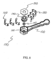
- FIG. 1 is an enlarged exploded perspective view of one configuration of the torque apparatus;
- FIG. 2A is a perspective view of the handle and head of the torque apparatus;
- FIG. 2B is a perspective view of an alternative handle configuration for the torque apparatus;
- FIG. 2C is a view of an additional handle configuration for the torque apparatus;
- FIG. 3A is an enlarged top view of a leaf spring section;
- FIG. 3B is an enlarged perspective view of a leaf spring section;
- FIG. 4A is an enlarged perspective view of the rotor showing the radial drive teeth;
- FIG. 4B is an enlarged sectional view of a portion of the rotor showing the asymmetrical sides of the drive teeth;
- FIG. 5 is an enlarged perspective view of one configuration of a hex drive insert;
- FIG. 6 is an enlarged top view of the head of a torque wrench with a pair of leaf springs, rotor, and drive insert installed showing the engagement between the leaf springs and the rotor drive teeth;
- FIG. 7 is a perspective view of the holding device for applying a controlled amount of torque; and
- FIG. 8 is a perspective view of the torque apparatus kit which includes a apparatus, a plurality of leaf springs, one or more rotors, and numerous drive inserts for common connector interfaces.
-
- Referring to the drawings in detail, and initially to FIG. 1,
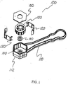
torque wrench 100 includes ahandle 110, ahead 112, at least oneleaf spring 120, at least onerotor 130, a plurality ofhex inserts 140, and acap 150. Whencap 150 is in position, it holdsrotor 130 and hex insert 140 in place withinhead 112.Cap 150 can be fixedly connected to head 112 using ultrasonic welding, or similar techniques, to form a hermitic seal, removably attached, or be an integral part ofhead 112. Thus,torque wrench 100 is configured to be easily sterilized as a hermitically sealed assembly or disassembled and sterilized using widely available sterilization techniques.Torque wrench 100 is configurable as either a disposable or reusable instrument. - Referring now to FIG. 2A,
torque wrench 100 has ahandle 110 on a first end, and ahead 112 on an opposing second end. Handle 110 contains a grip enhancing means 111 that includes ergonomic enhancements such as knurling, scalloping, or undulations that aid gripping.Head 112 hasside walls 113 that defineinternal cavity 114.Internal cavity 114 inhead 112 has a hexagonal shape in this configuration with twostops 116 on the inside ofside walls 113. Handle 110 andhead 112 are preferably made of plastic although other medical grade materials are also envisaged such as, e.g. stainless steel, titanium, etc. - In FIG. 2B an alternative configuration is shown which integrates handle 110 into
cap 150. In this configuration,cap 150 contains a grip enhancing means 111, such as knurling, scalloping, or radially extending undulations, and would enable the user to apply sufficient torque in the lower ranges of torque values. - In FIG. 2C an additional configuration is shown which integrates handle 110 into
head 112. In this configuration,head 112 contains a grip enhancing means 111, such as knurling, scalloping, or radially extending undulations, and would similarly enable the user to apply sufficient torque in the lower ranges of torque values. This configuration oftorque apparatus 100 could also be extended longitudinally to take the form of a screwdriver-torque wrench. - Referring now to FIG. 3A,
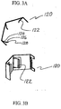
angular leaf spring 120 has a plurality of novel cantileveredbeam elements 122 that are sharply angled from a radial azimuth and are positioned to provide the torque limiting component of the design. Eachbeam element 122 has afirst section 124 and asecond section 126, which is defined by a second bend in thebeam element 122.Second bend section 126 facilitates sustaining the proper degree of physical interface at all times.Second section 126 has end with aninside end corner 128 that is coined with a radius profile that is designed to minimize frictional forces. - In FIG 3B,
leaf spring 120 is shown with angled cantileveredbeam elements 122. The number ofleaf spring elements 122 perleaf spring 120 can vary with the design application.Leaf spring 120 is preferably made from a sheet metal stamping. - Referring now to FIG. 4A, the
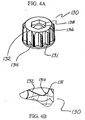
rotor 130 in this configuration has twelve simple radially extending singletoothed drive teeth 131. The quantity ofdrive teeth 131 can vary with the design application. Each driveteeth 131 has aclockwise ramp side 132 and a counterclockwiseflat side 134. The top ofrotor 130 defines ahexagonal cavity 136 withsidewalls 138.Rotor 130 is preferably made of medical grade plastic materials. - In FIG. 4B the asymmetrical nature of the sides of
drive teeth 131 ofrotor 130 is illustrated. In this configuration,clockwise ramp sides 132 are gradually sloped and counterclockwiseflat sides 134 are steeply angled. Additional asymmetrical configurations ofsides rotor 130 design can be reversed to have aflat side 134 in the clockwise direction and aramp side 132 in the counterclockwise direction. - Referring now to FIG. 5,
drive insert 140 functions as a drive mechanism interface for threaded connecting devices. In FIG. 5, a 9/32 inchhex drive insert 140 is shown that is specifically intended to interface with the CUSA EXcel 23 kHz product manufactured by Valleylab Inc. Thedrive insert 140 hex interface can also be configured for a 7/32inch hex drive 140 to interface with CUSA EXcel 36 kHz handpieces manufactured by Valleylab Inc.Additional drive insert 140 configurations could include interfaces for other hexagonal sizes as well as hex key, slot or phillips head screw driver, or any similar working member or attachment type device. All the drive inserts 140, such as the 7/32drive insert 140 and 9/32 insert have the same externalhexagonal sidewall 144 dimensions andshoulder 146 and are thus interchangeable. Driveinsert 140 is preferably made of metal, and in the removable cap configuration, is specifically designed to be easily changed in a sterile environment. - Referring now to FIG. 6,
torque wrench 100 is shown partially assembled. In this illustration, twoleaf springs 120 are installed inhead 112 between twostops 116 incavity 114.Torque wrench 100 can operate with one ormore leaf springs 120 to establish a different set of torque values at preset intervals. Torque values are preset in the hermetically sealed configuration and, in addition,torque wrench 100 can also be configured to be easily disassembled in so thatleaf springs 120 may be easily added to or removed fromhead 112 in a sterile environment.Rotor 130 is positioned withinhead 112 to engageleaf spring elements 122.Hex drive insert 140 can be a separate assembly and installed withinrotor 130 or be configured as an integral part of therotor 130. As installed withinrotor 130 as a separate assembly, thedrive insert 140 is inserted intohexagonal cavity 136.Sidewalls 144 ofrotor 140 then interface directly with thesidewalls 138 ofhexagonal cavity 136. The materials in the combined configuration ofrotor 130 and driveinsert 140 can include medical grade plastic or metal for both subassemblies or combinations of different materials bonded together. Driveinsert 140 has ashoulder 146 which rides between thehead 112 and therotor 130. Thedrive insert 140 is designed to be removable and replaceable in a sterile environment and is retained insiderotor 130 without a press fit or glue. - In operation, when the operator turns the
torque wrench 100 clockwise to tighten a working member, the bias of eachleaf spring element 122 turns rotor driveteeth 131,drive insert 140, and thus the threaded connecting device with the user's applied torque until the torque limit is exceeded. In this process, rampsides 132 engage a plurality of inside coinededges 128 ofsecond sections 126 ofbeam elements 122. The coining ofinside edge 128 creates an almost frictionless interface between theplastic rotor 130 andmetal beam element 122. With friction reduced, the user then only needs to increase the applied torque to rampside 132 to deflect and overcome the opposing counter force from the spring bias of the at least one angled leaf springcantilever beam element 122. The opposing counter force from each cantileveredbeam element 122 increases as it is deflected and applied clockwise torque approaches its maximum as theinside edge tip 128 ofsecond section 126 is forced upramp side 132. The applied torque peaks just prior toleaf spring element 122 releasingpast ramp side 132. The slippage of eachleaf spring element 122 up and overramp side 132 ofrotor drive teeth 131 defines a torque controlling mechanism that limits the applied torque to rotor driveteeth 131 and driveinsert 140. With the installation of oneleaf spring 120 inhead 112,torque wrench 100 achieves approximately 30 in-lbs in the clockwise direction before releasing for the CUSA EXcel 36 kHz instrument and, using two leaf springs, at least about 60 in-lbs for the CUSA EXcel 23 kHz instrument before leasing. - When an operator removes a working member with a counterclockwise rotation, a plurality of
flat sides 134 ofrotor 130 form flush interfaces with a plurality ofsecond beam sections 126 ofcantilevered beam elements 122. At this point,beam elements 122 are placed primarily in compression and secondarily in a transverse deflection. The working member removal torque necessary for theflat side 134 to compress thesecond beam 126 in the counterclockwise direction is at least about 1.5 times that of the installation torque of the maximum torque achieved byramp side 132 tosecond beam 126 interface just prior to releasing. When the maximum torque is exceeded, the torque controlling mechanism limits the applied torque to the rotor driveteeth 131 and driveinsert 140 by forcing the release or slippage ofleaf spring elements 122 past theflat side 134 ofrotor drive teeth 131.Wrench 100 is configured to provide an audible click that also has a distinct tactile indiction in the wrench with the rotation of everydrive tooth 131 or approximately every 30 degrees of rotation in this application.Rotor 130 is preferably made of a plastic type material that will minimize frictional forces between themetal beam element 122 andramp side 132 andflat side 134 ofdrive teeth 131. - Torque wrench subassemblies such as the
handle 110,head 112,leaf springs 120,rotor 130,drive insert 140, and cap 150 (see FIG. 1) may be combined to form a reduced total number of subassemblies. For example,rotor 130 and driveinsert 140 may be combined into a single subassembly,cap 150 can include handle 110, and in a similar manner, one ormore leaf springs 120 may be permanently installed intohead 112. - Referring now to FIG. 7, a holding
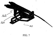
device 160 is provided in this embodiment to hold CUSA EXcel product line 23 kHz and 36 kHz surgical instrument handpieces, but could be configured to hold any number of devices. The holdingdevice 160 is intended to be reusable and is used in conjunction with the torque wrench while torquing working members or tips onto or removing them from CUSA handpieces.Holding device 160 has at least one pair ofgripping devices 162 for holding the metal portion of the instrument's handpiece and supports the overall body of the instrument. This reduces the risk of damage to the more fragile plastic areas of the handpiece. In addition, holdingdevice 160 provides the user with ahand hold 164 that provides a mechanical advantage during the torquing process. The design of holdingdevice 160 provides a rapidly cooling geometry which expedites cooling upon removal from an autoclave. - Referring now to FIG. 8, a
torque apparatus kit 170 which includes components such as one ormore torque wrenches 100, a set ofleaf springs 120, one ormore rotors 130, and a set of drive inserts 140 that provide flexibility of use in applications such as hex wrench, hex key, screwdriver, etc., and acap 150. - A set of
leaf springs 120 provides a range of torque values. Using one configuration of thecurrent torque wrench 100 that can employ up to two leaf springs, a first pair ofleaf springs 120 is mounted in the kit with a given torque value next to a second pair ofleaf springs 120 with a higher torque value. Eachleaf spring 120 would be labeled with its torque limit values in both directions of rotation when used individually, its increased torque values when used in combination with its pairedleaf spring 120, as well as its relative point of retention within the kit being labeled with its individual and paired torque values. In a similar manner, a set of drive inserts 140 providestorque wrench 100 with a range of inserts for application with different types of threaded connecting devices. - Although the illustrative embodiments of the present disclosure have been described herein with reference to the accompanying drawings, it is to be understood that the disclosure is not limited to those precise embodiments, and that various other changes and modifications may be affected therein by one skilled in the art without departing from the scope or spirit of the disclosure. All such changes and modifications are intended to be included within the scope of the disclosure.
Claims (10)
- A torque apparatus for applying a controlled amount of torque on threaded connections comprising:a handle;a head that is connected to said handle, said head defining an internal cavity;at least one leaf spring retained within the internal cavity, said leaf spring containing at least one leaf spring element; anda rotor positioned within the cavity of the head that includes an integral drive insert, said rotor containing asymmetrical sides of its plurality of radially extending drive teeth, said teeth positioned to engage said at last one leaf spring element in at least one rotational direction to produce a preset torque limit in at least one direction of rotation.
- The torque apparatus of any preceding claim, wherein the drive insert provides a hexagonal interface.
- The torque apparatus of any preceding claim, wherein the drive insert is a separate assembly that mates with a cavity in the rotor.
- The torque apparatus of any preceding claim, wherein the drive insert is monolithically formed as part of the rotor.
- The torque apparatus of any preceding claim, wherein the cavity defined in the head is hexagonal shaped.
- The torque apparatus of any preceding claim, wherein in the hexagonal cavity includes at least one stop that is configured to retain the at least one leaf spring.
- The torque apparatus of any preceding claim, wherein a cap is removably positioned over the cavity in the head.
- The torque apparatus of any preceding claim, wherein the cap includes a grip enhancing means.
- The torque apparatus of any preceding claim, wherein the cap grip enhancing means includes scalloping or knurling type devices.
- The torque apparatus of any preceding claim, wherein the asymmetrical sides of the rotor drive teeth includes a ramp side and a flat side.
Applications Claiming Priority (2)
| Application Number | Priority Date | Filing Date | Title |
|---|---|---|---|
| US472776 | 1983-03-07 | ||
| US09/472,776 US6499358B1 (en) | 1999-12-27 | 1999-12-27 | Apparatus for applying a controlled amount of torque |
Publications (3)
| Publication Number | Publication Date |
|---|---|
| EP1112818A2 true EP1112818A2 (en) | 2001-07-04 |
| EP1112818A3 EP1112818A3 (en) | 2002-06-12 |
| EP1112818B1 EP1112818B1 (en) | 2006-09-13 |
Family
ID=23876901
Family Applications (1)
| Application Number | Title | Priority Date | Filing Date |
|---|---|---|---|
| EP00127920A Expired - Lifetime EP1112818B1 (en) | 1999-12-27 | 2000-12-20 | An apparatus for applying a controlled amount of torque |
Country Status (5)
| Country | Link |
|---|---|
| US (1) | US6499358B1 (en) |
| EP (1) | EP1112818B1 (en) |
| JP (2) | JP2001300862A (en) |
| AU (1) | AU772456B2 (en) |
| DE (1) | DE60030670T2 (en) |
Cited By (6)
| Publication number | Priority date | Publication date | Assignee | Title |
|---|---|---|---|---|
| FR2876612A1 (en) * | 2004-10-19 | 2006-04-21 | Gautier Jacques | Spanner wrench for screwing e.g. screw, has driving body with lateral housings receiving flexible blades that are bent by edge of end piece when user applies tightening torque, where end piece is in complementary association with blades |
| EP1671751A1 (en) | 2004-12-14 | 2006-06-21 | Hu-Friedy Mfg. Co., Inc | Torque limiting wrench for ultrasonic scaler tip insertion |
| US7080582B2 (en) | 2004-02-13 | 2006-07-25 | Wiha Werkzeuge Gmbh | Screwdriver tool |
| CN102107414A (en) * | 2010-12-29 | 2011-06-29 | 浙江永和洁具有限公司 | Torsion warning device |
| EP2366499A1 (en) * | 2008-11-14 | 2011-09-21 | Biotechnology Institute, I Mas D, S.L. | Wrench for delivering maximum fixed or adjustable torque |
| EP2929982A1 (en) | 2014-04-07 | 2015-10-14 | Sandvik Intellectual Property AB | Torque wrench |
Families Citing this family (36)
| Publication number | Priority date | Publication date | Assignee | Title |
|---|---|---|---|---|
| US7299725B2 (en) * | 2006-03-07 | 2007-11-27 | Diba Industries, Inc. | Torque fastening devices and apparatuses |
| US20070254744A1 (en) * | 2006-04-27 | 2007-11-01 | Diba Industries, Inc. | Multi-use torque fitting |
| US7954857B2 (en) * | 2006-04-27 | 2011-06-07 | Diba Industries, Inc. | Assembly of multi-use torque fitting and length of tubing having compressible seal |
| US8574252B2 (en) | 2006-06-01 | 2013-11-05 | Ethicon Endo-Surgery, Inc. | Ultrasonic blade support |
| CA2581793A1 (en) * | 2006-07-20 | 2008-01-20 | Pilling Weck Incorporated | Semi automatic disposable torque limiting device and method |
| US7500418B2 (en) * | 2007-05-18 | 2009-03-10 | Toyota Motor Engineering & Manufacturing North America, Inc. | Torque setting lug nut wrench |
| USD767353S1 (en) | 2007-05-22 | 2016-09-27 | Ethicon Endo-Surgery, Llc | Torque wrench for ultrasonic instrument |
| US7984933B2 (en) * | 2008-02-28 | 2011-07-26 | Diba Industries, Inc. | Multi-use torque fitting and compressible ferrule |
| US20090254094A1 (en) * | 2008-04-08 | 2009-10-08 | Knapp Troy D | Ratcheting mechanical driver for cannulated surgical systems |
| US20090308174A1 (en) * | 2008-06-17 | 2009-12-17 | E & E Manufacturing Company, Inc. | Torsion tool tester |
| US20100094198A1 (en) * | 2008-10-14 | 2010-04-15 | Burgett Seth D | Systems and methods for tightening ophthalmic surgical needles |
| US8276487B2 (en) * | 2009-04-30 | 2012-10-02 | Medtronic, Inc. | Torque wrench for implantable medical devices |
| US8136431B2 (en) * | 2009-04-30 | 2012-03-20 | Medtronic, Inc. | Torque wrench for implantable medical devices |
| US8490525B2 (en) * | 2009-05-21 | 2013-07-23 | Pct International, Inc. | Coaxial connector torque application device |
| US8875387B2 (en) | 2009-06-15 | 2014-11-04 | Pct International, Inc. | Coaxial cable compression tool |
| US20110044584A1 (en) * | 2009-08-19 | 2011-02-24 | Diba Industries, Inc. | Optical fiber connection assembly |
| US9358672B2 (en) * | 2010-05-18 | 2016-06-07 | Gauthier Biomedical, Inc. | Electronic torque wrench |
| DE102012209417B4 (en) * | 2012-06-04 | 2017-10-26 | Atera Gmbh | Hand tool for torque transmission |
| JP6301357B2 (en) * | 2012-11-26 | 2018-03-28 | ゴーティエ バイオメディカル インコーポレイテッドGauthier Biomedical,Inc. | Driving tool |
| CH707490A1 (en) * | 2013-01-29 | 2014-07-31 | Hl Technology Sa | torque wrench. |
| US20150375380A1 (en) * | 2014-06-25 | 2015-12-31 | Torque-Tech Precision Co., Ltd. | Torque wrench with a reflection-type viewing window illumination structure |
| US9962181B2 (en) | 2014-09-02 | 2018-05-08 | Tenex Health, Inc. | Subcutaneous wound debridement |
| CN104897220B (en) * | 2015-06-18 | 2017-11-03 | 合肥精特仪表有限公司 | A kind of single rotor ultrasonic flowmeter |
| WO2017075129A1 (en) * | 2015-10-28 | 2017-05-04 | Ultra Clean Technology | Precision connections and methods of forming same |
| AU2017257421B2 (en) | 2016-04-25 | 2021-05-13 | Integra Lifesciences Enterprises, Lllp | Flue for ultrasonic aspiration surgical horn |
| USD820441S1 (en) | 2016-06-13 | 2018-06-12 | Integra Lifesciences Nr Ireland Limited | Surgical handpiece nosecone |
| US20170334046A1 (en) * | 2016-05-23 | 2017-11-23 | Titan Dental Systems, LLC | Torque-limiting and ratchetting mechanism |
| EP3463125B1 (en) | 2016-05-24 | 2022-08-31 | Integra LifeSciences Enterprises, LLLP | Ergonomic tubing attachment for medical apparatus |
| US10756482B2 (en) | 2016-09-20 | 2020-08-25 | Itt Manufacturing Enterprises Llc | Torque-limiting couplings |
| JP7030789B2 (en) | 2016-11-16 | 2022-03-07 | インテグラ ライフサイエンシーズ エンタープライジーズ, エルエルエルピー | Ultrasound Surgery Handpiece |
| US10687840B1 (en) | 2016-11-17 | 2020-06-23 | Integra Lifesciences Nr Ireland Limited | Ultrasonic transducer tissue selectivity |
| US10932807B2 (en) | 2017-02-08 | 2021-03-02 | Covidien Lp | Assembly tool for ultrasonic surgical instruments and kits and methods including the same |
| CN111051364B (en) | 2017-08-18 | 2023-03-14 | 飞纳技术有限公司 | Epoxidized polyfarnesenes and methods for making the same |
| KR102278631B1 (en) * | 2019-07-03 | 2021-07-16 | 윤준현 | Rotating coupling member having torque limiting function |
| DE102022103191A1 (en) | 2022-02-10 | 2023-08-10 | Ejot Se & Co. Kg | transmission device |
| CN218285316U (en) * | 2022-09-06 | 2023-01-13 | 思卓瑞(深圳)医疗科技有限公司 | Prevent supersound sword of overtightening and use torque wrench |
Citations (6)
| Publication number | Priority date | Publication date | Assignee | Title |
|---|---|---|---|---|
| US2461447A (en) * | 1943-06-30 | 1949-02-08 | Josephine M Siesel | Yielding drive |
| DE2350579A1 (en) * | 1973-10-09 | 1975-10-16 | Waltenberger Geb Lamla Margare | Multi-purpose nut spanner - has spring in hand grip able to operate torque indication light |
| US4926720A (en) * | 1986-03-15 | 1990-05-22 | Peter Wolter | Rachet spanner with open mouth |
| DE9003771U1 (en) * | 1990-03-31 | 1990-06-13 | Thalheim-Tachometerbau Kg, 3440 Eschwege, De | |
| US5224403A (en) * | 1992-04-06 | 1993-07-06 | Rueb Ward A | Predetermined torque yielding wrench |
| US5996453A (en) * | 1995-04-24 | 1999-12-07 | Hand Tool Design Corporation | Ratchet mechanism which resists spontaneous disengagement for use in wrenches and other tools |
Family Cites Families (19)
| Publication number | Priority date | Publication date | Assignee | Title |
|---|---|---|---|---|
| US3709087A (en) | 1970-09-10 | 1973-01-09 | W Stone | Torque limiting threaded fastener |
| US3960039A (en) | 1974-08-12 | 1976-06-01 | Star Dental Manufacturing Co., Inc. | Collet wrench |
| US4249435A (en) | 1979-07-30 | 1981-02-10 | Smith William J | Workpiece turning hand tool with torque control |
| CA1157693A (en) | 1980-01-11 | 1983-11-29 | Howard W. Biddle | Torque wrench |
| US4327610A (en) | 1980-06-02 | 1982-05-04 | Angelo Chiarenza | Open end ratchet wrench |
| DE8214536U1 (en) | 1982-05-18 | 1982-10-14 | Eduard Wille Gmbh & Co, 5600 Wuppertal | DEVICE FOR TIGHTENING A SCREW CONNECTION, IN PARTICULAR TIGHTENING THROUGH THE STRETCH LIMIT, BY MEANS OF THE ROTATIONAL ANGLE CONTROL |
| US4459882A (en) | 1982-05-19 | 1984-07-17 | Mikio Hayashi | Gear wrench with torque meter |
| US4644830A (en) * | 1982-09-27 | 1987-02-24 | Bailey Roy E | Ratchet wrench |
| US4913009A (en) * | 1988-08-29 | 1990-04-03 | Jackson Assembly Enterprises, Inc. | Ratchet wrench |
| US5059210A (en) | 1989-12-12 | 1991-10-22 | Ultracision Inc. | Apparatus and methods for attaching and detaching an ultrasonic actuated blade/coupler and an acoustical mount therefor |
| US5454283A (en) * | 1991-09-25 | 1995-10-03 | Stefano; Jerry Di. | Ratchet line wrench tool |
| US5366412A (en) | 1992-05-19 | 1994-11-22 | Implant Innovations, Inc. | Torque limiting clutch and its uses |
| JPH0776224A (en) | 1993-09-06 | 1995-03-20 | Aisin Seiki Co Ltd | Automatic sliding door |
| US5368480A (en) | 1993-12-08 | 1994-11-29 | Dentsply Research & Development Corp. | Dental implant wrench |
| US5571014A (en) | 1994-09-02 | 1996-11-05 | Snap-On Technologies, Inc. | Disposable torque limiting wrench |
| DE59503249D1 (en) | 1994-09-27 | 1998-09-24 | Straumann Inst Ag | Surgical torque wrench with a torque indicator |
| FR2756203B1 (en) | 1996-11-27 | 1999-02-12 | Facom | DYNAMOMETRIC KEY |
| US5810859A (en) | 1997-02-28 | 1998-09-22 | Ethicon Endo-Surgery, Inc. | Apparatus for applying torque to an ultrasonic transmission component |
| US5859371A (en) | 1997-07-03 | 1999-01-12 | Hsieh; Chih-Ching | Spring device of a torque wrench |
-
1999
- 1999-12-27 US US09/472,776 patent/US6499358B1/en not_active Expired - Lifetime
-
2000
- 2000-12-20 DE DE60030670T patent/DE60030670T2/en not_active Expired - Fee Related
- 2000-12-20 EP EP00127920A patent/EP1112818B1/en not_active Expired - Lifetime
- 2000-12-21 AU AU72450/00A patent/AU772456B2/en not_active Ceased
- 2000-12-27 JP JP2000404742A patent/JP2001300862A/en active Pending
-
2005
- 2005-10-26 JP JP2005311626A patent/JP2006075985A/en active Pending
Patent Citations (6)
| Publication number | Priority date | Publication date | Assignee | Title |
|---|---|---|---|---|
| US2461447A (en) * | 1943-06-30 | 1949-02-08 | Josephine M Siesel | Yielding drive |
| DE2350579A1 (en) * | 1973-10-09 | 1975-10-16 | Waltenberger Geb Lamla Margare | Multi-purpose nut spanner - has spring in hand grip able to operate torque indication light |
| US4926720A (en) * | 1986-03-15 | 1990-05-22 | Peter Wolter | Rachet spanner with open mouth |
| DE9003771U1 (en) * | 1990-03-31 | 1990-06-13 | Thalheim-Tachometerbau Kg, 3440 Eschwege, De | |
| US5224403A (en) * | 1992-04-06 | 1993-07-06 | Rueb Ward A | Predetermined torque yielding wrench |
| US5996453A (en) * | 1995-04-24 | 1999-12-07 | Hand Tool Design Corporation | Ratchet mechanism which resists spontaneous disengagement for use in wrenches and other tools |
Cited By (10)
| Publication number | Priority date | Publication date | Assignee | Title |
|---|---|---|---|---|
| US7080582B2 (en) | 2004-02-13 | 2006-07-25 | Wiha Werkzeuge Gmbh | Screwdriver tool |
| FR2876612A1 (en) * | 2004-10-19 | 2006-04-21 | Gautier Jacques | Spanner wrench for screwing e.g. screw, has driving body with lateral housings receiving flexible blades that are bent by edge of end piece when user applies tightening torque, where end piece is in complementary association with blades |
| EP1649980A1 (en) * | 2004-10-19 | 2006-04-26 | Gautier, Jacques | Torque limiting tool |
| EP1671751A1 (en) | 2004-12-14 | 2006-06-21 | Hu-Friedy Mfg. Co., Inc | Torque limiting wrench for ultrasonic scaler tip insertion |
| US7159494B2 (en) | 2004-12-14 | 2007-01-09 | Hu-Friedy Mfg. Co., Inc. | Torque limiting wrench for ultrasonic scaler tip insertion |
| EP2366499A1 (en) * | 2008-11-14 | 2011-09-21 | Biotechnology Institute, I Mas D, S.L. | Wrench for delivering maximum fixed or adjustable torque |
| EP2366499B1 (en) * | 2008-11-14 | 2015-08-19 | Biotechnology Institute, I Mas D, S.L. | Wrench for delivering maximum fixed or adjustable torque |
| CN102107414A (en) * | 2010-12-29 | 2011-06-29 | 浙江永和洁具有限公司 | Torsion warning device |
| CN102107414B (en) * | 2010-12-29 | 2012-07-04 | 浙江永和洁具有限公司 | Torsion warning device |
| EP2929982A1 (en) | 2014-04-07 | 2015-10-14 | Sandvik Intellectual Property AB | Torque wrench |
Also Published As
| Publication number | Publication date |
|---|---|
| DE60030670D1 (en) | 2006-10-26 |
| AU7245000A (en) | 2001-06-28 |
| JP2001300862A (en) | 2001-10-30 |
| DE60030670T2 (en) | 2007-10-04 |
| JP2006075985A (en) | 2006-03-23 |
| EP1112818A3 (en) | 2002-06-12 |
| US6499358B1 (en) | 2002-12-31 |
| EP1112818B1 (en) | 2006-09-13 |
| AU772456B2 (en) | 2004-04-29 |
Similar Documents
| Publication | Publication Date | Title |
|---|---|---|
| EP1112818B1 (en) | An apparatus for applying a controlled amount of torque | |
| EP2969395B1 (en) | Ratcheting torque wrench | |
| EP2566412B1 (en) | Cannulated ultra high torque device | |
| EP2566411B1 (en) | Ultra high torque device | |
| US5295831A (en) | Disposable torque wrench for dental components | |
| US7334509B1 (en) | Torque limiting driver and assembly | |
| EP1909673B1 (en) | Torque limiting device | |
| US7604640B2 (en) | Device and system for applying rotary impact | |
| EP2675595B1 (en) | International application for enhanced high torque device | |
| US6383189B1 (en) | Driver tool for bone distractor with shaft extension | |
| EP1257225B1 (en) | Dental hand instrument | |
| JP6334543B2 (en) | Insert tool | |
| US5366412A (en) | Torque limiting clutch and its uses | |
| US8985593B1 (en) | Self-locking internal adapter for D-shaped orthopedic adjustment tools | |
| EP3359341B1 (en) | Gearless spring washer high torque device | |
| EP3359839B1 (en) | Gearless compact torque drive | |
| US5571014A (en) | Disposable torque limiting wrench | |
| US20100107829A1 (en) | Torque limiting driver | |
| WO2014151067A1 (en) | Surgical ratchet tool, system and method | |
| EP3332735B1 (en) | Surgical instrument for dental implant | |
| EP2425930B1 (en) | Ratchet wrench | |
| EP3359837B1 (en) | Gearless torque drive | |
| EP3866727B1 (en) | Tool for use in dental implant treatments and retention element |
Legal Events
| Date | Code | Title | Description |
|---|---|---|---|
| PUAI | Public reference made under article 153(3) epc to a published international application that has entered the european phase |
Free format text: ORIGINAL CODE: 0009012 |
|
| AK | Designated contracting states |
Kind code of ref document: A2 Designated state(s): AT BE CH CY DE DK ES FI FR GB GR IE IT LI LU MC NL PT SE TR |
|
| AX | Request for extension of the european patent |
Free format text: AL;LT;LV;MK;RO;SI |
|
| RIN1 | Information on inventor provided before grant (corrected) |
Inventor name: HOGAN, MICHAEL P. Inventor name: SMALL, JASON P. Inventor name: RESCHKE, ARLAN J. Inventor name: NEAL, THOMAS G. |
|
| PUAL | Search report despatched |
Free format text: ORIGINAL CODE: 0009013 |
|
| AK | Designated contracting states |
Kind code of ref document: A3 Designated state(s): AT BE CH CY DE DK ES FI FR GB GR IE IT LI LU MC NL PT SE TR |
|
| AX | Request for extension of the european patent |
Free format text: AL;LT;LV;MK;RO;SI |
|
| RIN1 | Information on inventor provided before grant (corrected) |
Inventor name: HOGAN, MICHAEL P. Inventor name: RESCHKE, ARLAN J. Inventor name: SMALL, JASON P. Inventor name: NEAL, THOMAS G. Inventor name: DUFFIN, TERRANCE M Inventor name: SCHOENMAN, ARTHUR L. |
|
| 17P | Request for examination filed |
Effective date: 20020726 |
|
| AKX | Designation fees paid |
Designated state(s): DE ES FR GB IE IT |
|
| 17Q | First examination report despatched |
Effective date: 20040210 |
|
| RAP1 | Party data changed (applicant data changed or rights of an application transferred) |
Owner name: SHERWOOD SERVICES AG |
|
| GRAP | Despatch of communication of intention to grant a patent |
Free format text: ORIGINAL CODE: EPIDOSNIGR1 |
|
| GRAS | Grant fee paid |
Free format text: ORIGINAL CODE: EPIDOSNIGR3 |
|
| GRAA | (expected) grant |
Free format text: ORIGINAL CODE: 0009210 |
|
| RAP1 | Party data changed (applicant data changed or rights of an application transferred) |
Owner name: INTEGRA LIFESCIENCES (IRELAND) LTD. |
|
| AK | Designated contracting states |
Kind code of ref document: B1 Designated state(s): DE ES FR GB IE IT |
|
| PG25 | Lapsed in a contracting state [announced via postgrant information from national office to epo] |
Ref country code: IT Free format text: LAPSE BECAUSE OF FAILURE TO SUBMIT A TRANSLATION OF THE DESCRIPTION OR TO PAY THE FEE WITHIN THE PRESCRIBED TIME-LIMIT;WARNING: LAPSES OF ITALIAN PATENTS WITH EFFECTIVE DATE BEFORE 2007 MAY HAVE OCCURRED AT ANY TIME BEFORE 2007. THE CORRECT EFFECTIVE DATE MAY BE DIFFERENT FROM THE ONE RECORDED. Effective date: 20060913 |
|
| REG | Reference to a national code |
Ref country code: GB Ref legal event code: FG4D |
|
| REG | Reference to a national code |
Ref country code: IE Ref legal event code: FG4D |
|
| REF | Corresponds to: |
Ref document number: 60030670 Country of ref document: DE Date of ref document: 20061026 Kind code of ref document: P |
|
| PG25 | Lapsed in a contracting state [announced via postgrant information from national office to epo] |
Ref country code: IE Free format text: LAPSE BECAUSE OF NON-PAYMENT OF DUE FEES Effective date: 20061220 |
|
| PG25 | Lapsed in a contracting state [announced via postgrant information from national office to epo] |
Ref country code: ES Free format text: LAPSE BECAUSE OF FAILURE TO SUBMIT A TRANSLATION OF THE DESCRIPTION OR TO PAY THE FEE WITHIN THE PRESCRIBED TIME-LIMIT Effective date: 20061224 |
|
| EN | Fr: translation not filed | ||
| PLBE | No opposition filed within time limit |
Free format text: ORIGINAL CODE: 0009261 |
|
| STAA | Information on the status of an ep patent application or granted ep patent |
Free format text: STATUS: NO OPPOSITION FILED WITHIN TIME LIMIT |
|
| 26N | No opposition filed |
Effective date: 20070614 |
|
| PG25 | Lapsed in a contracting state [announced via postgrant information from national office to epo] |
Ref country code: FR Free format text: LAPSE BECAUSE OF FAILURE TO SUBMIT A TRANSLATION OF THE DESCRIPTION OR TO PAY THE FEE WITHIN THE PRESCRIBED TIME-LIMIT Effective date: 20070518 |
|
| PG25 | Lapsed in a contracting state [announced via postgrant information from national office to epo] |
Ref country code: FR Free format text: LAPSE BECAUSE OF FAILURE TO SUBMIT A TRANSLATION OF THE DESCRIPTION OR TO PAY THE FEE WITHIN THE PRESCRIBED TIME-LIMIT Effective date: 20060913 |
|
| PGFP | Annual fee paid to national office [announced via postgrant information from national office to epo] |
Ref country code: DE Payment date: 20081230 Year of fee payment: 9 |
|
| PGFP | Annual fee paid to national office [announced via postgrant information from national office to epo] |
Ref country code: GB Payment date: 20081110 Year of fee payment: 9 |
|
| GBPC | Gb: european patent ceased through non-payment of renewal fee |
Effective date: 20091220 |
|
| PG25 | Lapsed in a contracting state [announced via postgrant information from national office to epo] |
Ref country code: DE Free format text: LAPSE BECAUSE OF NON-PAYMENT OF DUE FEES Effective date: 20100701 |
|
| PG25 | Lapsed in a contracting state [announced via postgrant information from national office to epo] |
Ref country code: GB Free format text: LAPSE BECAUSE OF NON-PAYMENT OF DUE FEES Effective date: 20091220 |