EP1112821A1 - Toboy device and method for controlling the same - Google Patents
Toboy device and method for controlling the same Download PDFInfo
- Publication number
- EP1112821A1 EP1112821A1 EP00925595A EP00925595A EP1112821A1 EP 1112821 A1 EP1112821 A1 EP 1112821A1 EP 00925595 A EP00925595 A EP 00925595A EP 00925595 A EP00925595 A EP 00925595A EP 1112821 A1 EP1112821 A1 EP 1112821A1
- Authority
- EP
- European Patent Office
- Prior art keywords
- robot system
- motion
- battery
- emotion
- attitude
- Prior art date
- Legal status (The legal status is an assumption and is not a legal conclusion. Google has not performed a legal analysis and makes no representation as to the accuracy of the status listed.)
- Withdrawn
Links
- 238000000034 method Methods 0.000 title claims abstract description 20
- 230000033001 locomotion Effects 0.000 claims abstract description 174
- 230000008451 emotion Effects 0.000 claims abstract description 145
- 238000013459 approach Methods 0.000 claims description 8
- 230000005540 biological transmission Effects 0.000 claims description 8
- 238000004891 communication Methods 0.000 claims description 5
- 230000002829 reductive effect Effects 0.000 claims description 4
- 230000007704 transition Effects 0.000 description 55
- 238000012545 processing Methods 0.000 description 29
- 238000001514 detection method Methods 0.000 description 18
- 241001465754 Metazoa Species 0.000 description 13
- 230000014509 gene expression Effects 0.000 description 12
- 230000036528 appetite Effects 0.000 description 11
- 235000019789 appetite Nutrition 0.000 description 11
- 230000003247 decreasing effect Effects 0.000 description 11
- 230000006870 function Effects 0.000 description 11
- 238000005452 bending Methods 0.000 description 10
- 230000007423 decrease Effects 0.000 description 8
- 238000010586 diagram Methods 0.000 description 8
- 230000002996 emotional effect Effects 0.000 description 8
- 210000001015 abdomen Anatomy 0.000 description 4
- 238000006243 chemical reaction Methods 0.000 description 3
- 241000282326 Felis catus Species 0.000 description 2
- 238000001816 cooling Methods 0.000 description 2
- 230000036961 partial effect Effects 0.000 description 2
- 230000000284 resting effect Effects 0.000 description 2
- 238000001228 spectrum Methods 0.000 description 2
- 210000000352 storage cell Anatomy 0.000 description 2
- 229920003002 synthetic resin Polymers 0.000 description 2
- 239000000057 synthetic resin Substances 0.000 description 2
- 230000002123 temporal effect Effects 0.000 description 2
- 206010001513 AIDS related complex Diseases 0.000 description 1
- 101150106709 ARC1 gene Proteins 0.000 description 1
- 101100013575 Arabidopsis thaliana FTSHI1 gene Proteins 0.000 description 1
- 101100447334 Arabidopsis thaliana FTSZ1 gene Proteins 0.000 description 1
- 241000238631 Hexapoda Species 0.000 description 1
- 206010041349 Somnolence Diseases 0.000 description 1
- 230000005856 abnormality Effects 0.000 description 1
- 210000002945 adventitial reticular cell Anatomy 0.000 description 1
- 239000000956 alloy Substances 0.000 description 1
- 229910045601 alloy Inorganic materials 0.000 description 1
- 239000003086 colorant Substances 0.000 description 1
- 230000002950 deficient Effects 0.000 description 1
- 230000000694 effects Effects 0.000 description 1
- 230000000670 limiting effect Effects 0.000 description 1
- 239000002184 metal Substances 0.000 description 1
- 238000013021 overheating Methods 0.000 description 1
- 230000008447 perception Effects 0.000 description 1
- 210000001364 upper extremity Anatomy 0.000 description 1
- 230000000007 visual effect Effects 0.000 description 1
Images


Classifications
-
- B—PERFORMING OPERATIONS; TRANSPORTING
- B25—HAND TOOLS; PORTABLE POWER-DRIVEN TOOLS; MANIPULATORS
- B25J—MANIPULATORS; CHAMBERS PROVIDED WITH MANIPULATION DEVICES
- B25J13/00—Controls for manipulators
-
- G—PHYSICS
- G06—COMPUTING; CALCULATING OR COUNTING
- G06N—COMPUTING ARRANGEMENTS BASED ON SPECIFIC COMPUTATIONAL MODELS
- G06N3/00—Computing arrangements based on biological models
- G06N3/004—Artificial life, i.e. computing arrangements simulating life
- G06N3/008—Artificial life, i.e. computing arrangements simulating life based on physical entities controlled by simulated intelligence so as to replicate intelligent life forms, e.g. based on robots replicating pets or humans in their appearance or behaviour
-
- B—PERFORMING OPERATIONS; TRANSPORTING
- B25—HAND TOOLS; PORTABLE POWER-DRIVEN TOOLS; MANIPULATORS
- B25J—MANIPULATORS; CHAMBERS PROVIDED WITH MANIPULATION DEVICES
- B25J19/00—Accessories fitted to manipulators, e.g. for monitoring, for viewing; Safety devices combined with or specially adapted for use in connection with manipulators
- B25J19/005—Accessories fitted to manipulators, e.g. for monitoring, for viewing; Safety devices combined with or specially adapted for use in connection with manipulators using batteries, e.g. as a back-up power source
-
- B—PERFORMING OPERATIONS; TRANSPORTING
- B25—HAND TOOLS; PORTABLE POWER-DRIVEN TOOLS; MANIPULATORS
- B25J—MANIPULATORS; CHAMBERS PROVIDED WITH MANIPULATION DEVICES
- B25J19/00—Accessories fitted to manipulators, e.g. for monitoring, for viewing; Safety devices combined with or specially adapted for use in connection with manipulators
- B25J19/0054—Cooling means
Definitions
- the present invention relates to a robot system and a control method thereof, and is suitably applicable to for example a pet robot.
- a tail of the pet robot of this kind a tail that will be shaken in vertical direction or lateral direction according to drive of actuators built in the rear end of the body part has been provided, not only a tail in the shape of a cord that has been simply hung from the rear end of the body part.
- a battery being a storage cell provided inside the body has been used as a main power supply.
- Various circuits or actuators will be respectively based on electric power to be supplied from the above battery.
- the tail is not required to move as the occasion demands as the legs.
- the tail can be freely moved at any time. For that reason, it is further desirable that when a trouble happened inside the pet robot, the fact can be informed the unit by the motion of the tail.
- a driving system including the battery has been provided in the body part.
- a ventilating opening has been formed at a predetermined position of the body part. External air will be let into the body part via the above ventilating opening. Thus, the internal temperature of the body part can be prevented from extremely raising.
- the present invention provides a robot system and a control method thereof in that amusement characteristic can be remarkably improved on the other hand the necessity of battery charging can be represented by an attitude and its safety can be ensured.
- a robot system having a movable part of which one end has been connected freely in rotation in the direction of at least one axis or more, motion control means for operating the movable part according to input information to be supplied, and emotion/instinct model changing means having emotion/instinct models caused by motions, for changing the emotion/instinct model based on the input information and determining the motion of the movable part have been provided.
- emotion/instinct model changing means having emotion/instinct models caused by motions, for changing the emotion/instinct model based on the input information and determining the motion of the movable part have been provided.
- detecting means for detecting the internal state of the robot system and motion control means for operating the movable part according to the detected result by the detecting means have been provided.
- the internal state of the above robot can be represented by the motion of movable parts and an attitude.
- reaction like an animal can be shown to the user, and a sense of affinity and a feeling of satisfaction can be given to the user.
- a robot system having a battery built-in as a power source, remaining amount of battery detecting means for detecting the remaining amount of the battery, and motion control means, if the remaining amount of the battery detected by the remaining amount of battery detecting means becomes a prescribed level or below, for changing the robot system into a predetermined attitude and/or making it appear a predetermined motion have been provided.
- this robot system a manner that it appeals its appetite as if it is a true animal can be transmitted to the user and giving the user a sense of affinity and a feeling of satisfaction; its amusement characteristic can be remarkably improved.
- thermodetecting means for detecting the internal temperature of the body part
- motion control means if the internal temperature detected by the temperature detecting means becomes a prescribed temperature and over, for changing the robot system into a predetermined attitude and/or making it appear a predetermined motion have been provided.
- the first step of detecting the remaining amount of the battery, and the second step, if the above detected remaining amount of the battery becomes a prescribed level or below, of changing the robot system into a predetermined attitude and/or making it appear a predetermined motion have been provided.
- the robot system can be controlled so that a manner that it appeals its appetite as if it is a true animal can be transmitted to the user and giving the user a sense of affinity and a feeling of satisfaction.
- a method of controlling a robot system in that its amusement characteristic can be remarkably improved can be realized.
- the first step of detecting the internal temperature of the body part, and the second step if the internal temperature detected by the temperature detecting means becomes a prescribed temperature and over, of changing the robot system into a predetermined attitude and/or making it appear a predetermined motion have been provided.
- the robot system can be controlled so that trouble of the power source in this pet robot system can be prevented.
- Fig. 1 is a perspective view showing the structure of a pet robot system to which the present invention has applied.
- Fig. 2 is a perspective view showing the structure of the pet robot.
- Fig. 3 is a perspective view showing the structure of the pet robot of Fig. 1.
- Fig. 4 is a perspective view showing the structure of a station in Fig. 1.
- Fig. 5 is a block diagram showing the configuration of the pet robot of Fig. 1.
- Fig. 6 is a schematic diagram showing a tail part in a tail unit.
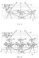
- Fig. 7 is a schematic perspective view showing the internal structure of a base part in the tail unit.
- Fig. 8 is a partial sectional view showing the internal structure of a gearbox in the base part of Fig. 7.
- Figs. 9A and 9B are partial sectional views for explaining the operating state of a differential gear mechanism in the gear box of Fig. 8.
- Fig. 10 is a schematic perspective view showing the general structure of the tail unit.
- Fig. 11 is a schematic diagram for explaining data processing by a controller.
- Fig. 12 is a schematic diagram for explaining data processing by an emotion/instinct model part.
- Fig. 13 is a schematic diagram for explaining data processing by the emotion/instinct model part.
- Fig. 14 is a schematic diagram for explaining data processing by the emotion/instinct model part.
- Fig. 15 is a schematic diagram for explaining data processing by the emotion/instinct model part.
- Fig. 16 is a schematic diagram for explaining data processing by the emotion/instinct model part.
- Fig. 17 is the state transition view of finite automaton in a motion determination mechanism part.
- Fig. 18 is an attitude transition view in an attitude transition mechanism part.
- Fig. 19 is a flowchart for explaining battery charging request processing procedure.
- Fig. 20 is a flowchart for explaining internal temperature control processing procedure.
- a reference numeral 1 generally shows a pet robot system of this embodiment.
- a pet robot 2 is put on the specified position of a dedicated battery charger (hereinafter, this is referred to as station) 3 in a predetermined attitude, a battery (not shown) built in the above pet robot 2 is charged.
- station a dedicated battery charger
- leg units 5A to 5D have been respectively connected to the front and rear on the both sides of a body unit 4 and a head unit 6 and a tail unit 7 have been respectively connected to the front end part and the rear end part of the body unit 4.
- a tail part 7T has been pulled out from a base part 7B provided on the top side of the body unit 4 with two flexibility, freely in bent and swing.
- a cooling fan (not shown) has been provided inside this body unit 4.
- An exhausting opening 4AX and an intake 4BX via the above cooling fan have been formed on a top side 4A and a bottom side 4B respectively. Therefore, in the pet robot 2, the internal temperature of the above body unit 4 can be lowered by exhausting the air taken from the intake 4BX to the outside from the exhausting opening 4AX via the inside of the body unit 4.
- a first connector half body 4C composed of exposed plural electrodes (pads) (not shown) has been provided.
- a recessed space 3AH which is corresponding to the body unit 4 of the pet robot 2 has been formed at the center of the top side of a main body part 3A, and flat surfaces 3AR and 3AL have been respectively formed on the both sides of the above recessed space 3AH along the longitudinal direction.
- a second connector half body 3C in which an electrode terminal (not shown) has been projectively formed has been provided corresponding to each electrode of the first connector half body 4C on the pet robot 2.
- LED lamps 3L On the front side of the main body part 3A of the station 3, plural light emitting diode (LED) lamps 3L have been provided. They inform the user of whether or not the plug of the AC adapter (not shown) connected to the station 3 by line has been connected to the power supply, whether or not the battery (not shown) provided in the pet robot 2 has been charged or whether or not a spare battery housed in the station 3 freely detachable has been charged, by turning on or turning on and off respectively in prescribed light emitting colors.
- LED light emitting diode
- attitude to shift to station When the pet robot 2 is practically combined with the station 3, the pet robot 2 should be first changed into an attitude of 'lie down.', i.e. an attitude so that each of the leg units 5A to 5C are bent and the bottom side 4B of the body unit 4 is closed to the floor (hereinafter, this attitude is referred to as attitude to shift to station).
- the user should lift up the pet robot 2 and putting on it so that the body unit 4 is engaged in the recessed space 3AH on the station 3. Thereby, the first connector half body 4C on the body unit 4 and the second connector half body 3C on the station 3 are abutted and connected by line.
- the body unit 4 of the pet robot 2 contains a controller 10 for controlling general motions of this pet robot 2, a battery 11 being the power source of this pet robot 2, an internal sensor part 14 composed of a battery sensor 12, etc.
- a charge coupled device (CCD) camera 16 which corresponds to "eye”
- a touch sensor 17 which corresponds to "mouse”, etc.
- CCD charge coupled device
- Actuators 5AA 1 to 5AA K , 5BA 1 to 5BA K , 5CA 1 to 5CA K , 5DA 1 to 5DA K , 6A 1 to 6A L , 7A 1 and 7A 2 have been respectively disposed at the respective joint parts of the leg units 5A to 5D, the respective joined parts of the leg units 5A to 5D and the body unit 4, the joined part of the head unit 6 and the body unit 4, and the joined part of the tail unit 7 and the body unit 4.
- the microphone 15 in the head unit 6 picks up an instructing voice such as "walk.”, “lie down.”, “follow the ball.” or the like that was given from the user as a musical scale by means of a sound commander not shown (commander for generating sounds different in musical scale corresponding to operating contents), and transmitting thus obtained voice signal S1 to the controller 10.
- the CCD camera 16 picks up an image around the pet robot 2, and transmitting thus obtained image signal S2 to the controller 10.
- the touch sensor 17 has been provided at the top of the head unit 6 as shown in Fig. 2. It detects a pressure received by physical approaches from the user, such as "stroked”, “slapped” or the like, and transmitting the detected result to the controller 10 as a pressure detection signal S3.
- the battery sensor 12 in the body unit 4 detects the remaining amount of the battery 11 in five phased levels, and sequentially transmitting the detected result in the above levels to the controller 10 as a remaining amount of battery detection signal S4.
- the battery sensor 12 detects the remaining amount of the battery 11 in phased levels when it is 80 [%] and over, 80 to 50 [%], 50 to 25 [%], 25 to 20 [%], and 20 [%] or below, respectively as "Full”, "Middle-Full", “Middle”, “Low” and “Low-Low”.
- thermosensor 13 in the body unit 4 detects the internal temperature of the pet robot 2, and transmitting the detected result to the controller 10 as a heat detection signal S5.
- the controller 10 determines the state around the pet robot 2, the presence of instructions or approaches from the user or the like, based on the voice signal S1, image signal S2, pressure detection signal S3, remaining amount of battery detection signal S4 and heat detection signal S5 given from the microphone 15, CCD camera 16, touch sensor 17, battery sensor 12 and thermosensor 13.
- the controller 10 decides the following motion based on these determined results and a control program that has been previously entered. It makes a necessary actuator 5AA 1 to 5AA K , 5BA 1 to 5BA K , 5CA 1 to 5CA K , 5DA 1 to 5DA K , 6A 1 to 6A L , 7A 1 and 7A 2 drive based on the decision result, and driving each of the leg units 5A to 5D.
- the pet robot 2 performs motions such as vertically and laterally shaking the head unit 6, moving the tail unit 7, walking, etc.
- the controller 10 supplies a predetermined voice signal S6 to the speaker 18 as the occasion demands, and generating a voice based on the above voice signal S6 to the outside, or it makes LEDs (not shown) provided at the position of "eye" of this pet robot 2 turn on, off or on and off.
- this pet robot 2 can be autonomously moved according to the state around it, the control program, and so on.
- one end of the tail part 7T has been connected to a gearbox (not shown) in the base part 7B provided on the top of the body unit 4.
- this tail part 7T forms curved mechanism composed of two pieces of almost parallel wire parts 7WA and 7WB forming a hair pin shape by bending for instance a piece of wire 7W made of very elastic alloy in almost U shape (or in almost V shape) at the center part.
- a pin 7P has been put perpendicularly to the axis direction, and holding the bent part 5WC of the wire 7W by abutting. Thereby, the wire 7W can be prevented from slipping out of the cylindrical member 7PA.
- the base ends 7WAS and 7WBS of the two pieces of wire parts 7WA and 7WB have been projected in bending in almost L shape to mutually counter directions, and respectively connected to a gearbox 22 (Fig. 7) that will be described later.
- Fig. 7 shows the internal structure of a base cover (not shown) in the base part 7B.
- a pair of actuators 7A 1 and 7A 2 formed by geared motors have been fixed to the back plate 20A of a bearing member 20 formed in almost U-shaped section.
- the output shafts 7A 1X and 7A 2X of the above actuators 7A 1 and 7A 2 have been penetrated respectively inside via the respective through holes 20AH formed on the back plate 20A.
- a gear transmission mechanism 21 has been provided.
- the output shafts 7A 1X and 7A 2X of the actuators 7A 1 and 7A 2 have been engaged with the gearbox 22 via the above gear transmission mechanism 21. That is, in this gear transmission mechanism 21, helical gears 23A and 23B fixed to the output shafts 7A 1X and 7A 2X of the actuators 7A 1 and 7A 2 , and helical gears 26A and 26B fitted freely in rotation centering around a first and a second shafts 24 and 25 supported between the top plate 20B and the bottom plate 20C of the bearing member 20 have been respectively engaged.
- a gear 27A which rotates centering around the above first shaft 24 has been combined with the helical gear 26A in one unit body.
- a gear 27B which rotates centering around the above second shaft 25 has been combined with the helical gear 26B in one unit body.
- gears 29 and 30 At the top end and the bottom end of a third shaft 28 supported between the top plate 20B and the bottom plate 20C of the bearing member 20, gears 29 and 30 have been respectively fitted freely in rotation centering around the above third shaft 28.
- the gear 29 on the top end has been engaged with the gear 27A fitted at the top end of the first shaft 24.
- gear 30 on the bottom end has been engaged with the gear 27B fitted to the bottom end of the second shaft 25.
- this gearbox 22 forms a spherical shell body 22A in which a pair of half-spherical shell bodies 22A 1 and 22A 2 have been combined. And it has been formed so that a differential gear mechanism 35 has been built in a hollow part 22H in the above spherical shell body 22A so as to be engaged with the fourth and fifth shafts 31 and 32.
- This differential gear mechanism 35 has a spindle 36 that has been held freely in rotation in the spherical shell body 22A so as to be orthogonalized to the fourth and fifth shafts 31 and 32.
- a slide guide 41 made of synthetic resin or the like has been fitted freely in rotation centering around the above spindle 36 so that the longitudinal direction is orthogonal to the spindle 36, and also a vertical pair of sliders 42A and 42B have been engaged with the slide guide 41 freely in sliding in the longitudinal direction so that the above spindle 36 is held between them.
- a vertical pair of guide rails 41A and 41B which are in parallel have been formed along the longitudinal direction.
- guide grooves 42AG and 42BG have been respectively formed corresponding to the above guide rails 41A and 41B.
- one end of the wire parts 7WA and 7WB have been respectively embedded along the groove direction to support the entire tail part 7T.
- a vertical pair of projections 38A and 38B having pin shapes have been formed in one unit body so as to keep the positional relationship of mutually 180 [° ].
- a vertical pair of slide grooves 42AH and 42BH which are parallel to the fourth and fifth shafts 31 and 32 have been formed respectively corresponding to the above projections 38A and 38B.
- the vertical pair of gears 33 and 34 fitted to the fourth and the fifth shafts 31 and 32 through the gear transmission mechanism 21 are rotated in the mutually inverse directions (an arrow "b" direction and the inverse direction) in one unit body to the vertical pair of small diameter bell-shaped gears 39 and 40 forming the differential gear mechanism 35.
- the lateral pair of large diameter bell-shaped gears 37 and 38 forming the differential gear mechanism 35 pushes out one of the pair of sliders 42A and 42B in the longitudinal direction of the slide guide 41, and at the same time, pulls back the other, while rotating in the mutually inverse directions (the arrow "a" direction and the inverse direction).
- the two pieces of wire parts 7WA and 7WB in the tail part 7T are mutually pushed out or pulled back according to the sliding motion of the sliders 42A and 42B by the differential gear mechanism 35 in the gearbox 22, so that the wire 7W can be bent.
- the tail part 7T can be bent in the vertical direction at a desired amplitude or can be shaken in the vertical direction at a desired amplitude and speed according to the above drive control.
- the vertical pair of gears 33 and 34 fitted to the fourth and the fifth shafts 31 and 32 via the gear transmission mechanism 21 are rotated in the same direction (the arrow "b" direction or the inverse direction).
- the vertical pair of small diameter bell-shaped gears 39 and 40 forming the differential gear mechanism 35 cannot be rotated in the same direction because they have been engaged with both the lateral pair of large diameter bell-shaped gears 37 and 38.
- the differential gear mechanism 35 i.e. the gearbox 22 is rotated in the same direction as the vertical pair of gears 33 and 34 in one unit body centering around the fourth and fifth shafts 31 and 32.
- the tail unit 7 As shown in Fig. 10, when the pair of actuators 7A 1 and 7A 2 are drive-controlled so that the output shafts 7A 1X and 7A 2X are rotated in the mutually same direction at the same rotating speed, the gearbox 22 and the inside differential gear mechanism 35 are rotated in a desired direction according to the above drive control.
- the tail part 7T can be bent in an arrow "c" direction or the inverse lateral direction, or an arrow "d" direction or the vertical direction inverse to that, or the like at a desired amplitude, or can be shaken in the lateral direction at a desired amplitude and speed.
- a sensor input processing part 50 for recognizing a specified external state
- an emotion/instinct model part 51 for representing the state of emotion and instinct by accumulating the recognition result by the above sensor input processing part 50
- a motion determination mechanism part 52 for determining the following motion based on the recognition result by the above sensor input processing part 50
- an attitude transition mechanism part 53 for making the pet robot 2 practically appear a motion based on the determined result by the above motion determining mechanism part 52 and the representation result by the above emotion/instinct model part 51
- a control mechanism part 54 for drive-controlling each of the actuators 5AA 1 to 7A 1 and 7A 2 .
- the sensor input processing part 50 detects and recognizes the specified external state, specified approaches from the user and instructions from the user based on the voice signal S1, the image signal S2 and the pressure detection signal S3 supplied from the microphones 15, the CCD camera 16 and the touch sensor 17. Thereafter, the sensor input processing part 50 converts the above recognition results into a hearing state, a visual state and a perception state that true animals feel. At the same time, it recognizes the state of remaining amount of the battery 11 and the internal temperature of the pet robot 2 based on the remaining amount of battery detection signal S4 and the heat detection signal S5 supplied from the battery sensor 12 and the thermosensor 13 forming the internal sensor part 14. Thus obtained state recognition information D1 is informed the emotion/instinct model part 51 and the motion determining mechanism part 52.
- the sensor input processing part 50 monitors the voice signal S1 supplied from the microphones 15 at all times. And when a spectrum having the same musical scale as a command sound that is supplied from a sound commander (not shown) is detected according to a command such as "walk.” “lie down.” “follow the ball.”, etc. as a spectrum of the above voice signal S1, it recognizes that the command has given, and informing the emotion/instinct model part 51 and the motion determining mechanism part 52 the above recognition result.
- the sensor input processing part 50 monitors the image signal S2 supplied from the CCD camera 16 at all times. And when for example “a red round object” or “a level perpendicular to the ground and being a predetermined height or more” has detected in an image based on the image signal S2, it recognizes that "there is a ball.”, "there is a wall.”, and informing the emotion/instinct model part 51 and the motion determining mechanism part 52 the above recognition result.
- the sensor input processing part 50 monitors the pressure detection signal S3 supplied from the touch sensor 17 at all times. And when a pressure at a predetermined threshold value or more and in a short period (e.g. less than 2 minute) has detected based on the above pressure detection signal S3, it recognizes that the pet robot 2 was "slapped (scolded)". When a pressure at less than the predetermined threshold value and for a long period (e.g. 2 seconds or more) has detected based on the above pressure detection signal S3, it recognizes that the pet robot 2 was stroked (praised)", and informing the emotion/instinct model part 51 and the motion determining mechanism part 52 the recognition result.
- a predetermined threshold value or more and in a short period e.g. less than 2 minute
- the sensor input processing part 50 monitors the remaining amount of battery detection signal S4 supplied from the battery sensor 12 at all times to recognize whether the remaining amount of the battery 11 is 80 [%] and over, 50 to 25 [%], 25 to 20 [%] or 20 [%] or below based on the above remaining amount of battery detection signal S4, and informing the emotion/instinct model part 51 and the motion determining mechanism part 52 the above recognition result.
- the sensor input processing part 50 monitors the heat detection signal S5 supplied from the thermosensor 13 at all times. And when that the internal temperature of the pet robot 2 is a prescribed critical temperature and over has detected based on the above heat detection signal S5, it recognizes "it is critical", and informing the emotion/instinct model part 51 and the motion determining mechanism part 52 the above recognition result.
- the emotion/instinct model part 51 has control parameters on a basic emotion group 60 composed of emotion units 60A to 60D as plural independent emotion models and a basic wants group 61 composed of wants units 61A to 61D as plural independent wants models in the memory 10A of the controller 10.
- the emotion unit 60A shows an emotion "be glad”
- the emotion unit 60B shows an emotion “be sad”
- the emotion unit 60C shows an emotion "be angry”.
- the emotion units 60A to 60D respectively represent the degree of emotion by for example intensity in levels 0 to 100.
- the intensity of the emotions respectively changes every moment based on the state recognition information D1 to be supplied.
- the emotion/instinct model part 51 combines the intensity of the emotion units 60A to 60D changing every moment, and representing the state of emotion of the pet robot 2 and modeling the temporal change of its emotion.
- the wants unit 61A shows wants of "appetite”
- the wants unit 61B shows wants of “curiosity”
- the wants unit 61C shows wants for "exercise”.
- the wants units 61A to 61D respectively represent the degree of wants by for example intensity in levels 0 to 100.
- the intensity of wants respective changes every moment based on the state recognition information D1 to be supplied.
- the emotion/instinct model part 51 combines the intensity of the wants units 61A to 61D changing every moment, and representing the state of instinct of the pet robot 2 and modeling the temporal change of its instinct.
- the emotion/instinct model part 51 changes respectively the intensity of the emotion units 60A to 60D and the wants units 61A to 61D based on the state recognition information D1. Then, the emotion/instinct model part 51 accumulatively combines thus changed intensity of the emotion units 60A to 60D and determining a state of emotion, and accumulatively combines thus changed intensity of the wants units 61A to 61D and determining a state of instinct.
- the above determined states of emotion and instinct are transmitted to the motion determining mechanism part 52 as emotion/instinct state information D2.
- the emotion/instinct model part 51 mutually inhivitively or mutually stimulatively combines desired two of the emotion units 60A to 60D in the basic emotion group 60. If the intensity of one of the above combined emotion units 60A to 60D is changed, the intensity of the other emotion unit is changed corresponding to this. Thus, a pet robot having natural emotion will be accomplished.
- the emotion/instinct model part 51 increases the intensity of the "glad” emotion unit 60A. And at the time, even if the state recognition information D1 that changes the intensity of the "sad” emotion unit 60B was not supplied, the emotion/instinct model part 51 naturally decreases the intensity of the "sad” emotion unit 60B corresponding to the increase of the intensity of the "glad” emotion unit 60A.
- the emotion/instinct model part 51 naturally decreases the intensity of the "glad” emotion unit 60A corresponding to the increase of the intensity of the above "sad” emotion unit 60B.
- the emotion/instinct model part 51 increases the intensity of the "angry” emotion unit 60C. And at the time, even if the state recognition information D1 that changes the intensity of the "sad” emotion unit 60B was not supplied, the emotion/instinct model part 51 naturally increases the intensity of the "sad” emotion unit 60B corresponding to the increase of the intensity of the "angry” emotion unit 60C.
- the emotion/instinct model part 51 naturally increases the intensity of the "angry” emotion unit 60C corresponding to the increase of the intensity of the above "sad” emotion unit 60B.
- the emotion/instinct model part 51 increases the intensity of the "appetite” wants unit 61A. And at the time, even if the state recognition information D1 that changes the intensity of the "exercise” wants unit 61B was not supplied, the emotion/instinct model part 51 naturally decreases the intensity of the "exercise” wants unit 61B corresponding to the increase of the "appetite” wants unit 61A.
- the emotion/instinct model part 51 naturally decreases the intensity of the "appetite” wants unit 61A corresponding to the increase of the intensity of the above "exercise” wants unit 61B.
- the emotion/instinct model part 51 increases the intensity of the "exercise” wants unit 61C. And at the time, even if the state recognition information D1 that changes the intensity of the "curiosity” wants unit 61B was not supplied, the emotion/instinct model part 51 naturally increases the intensity of the "curiosity” wants unit 61B corresponding to the increase of the intensity of the "exercise” wants unit 61C.
- the emotion/instinct model part 51 naturally increases the intensity of the "exercise” wants unit 61C corresponding to the increase of the intensity of the above "curiosity” wants unit 61B.
- motion information D3 which shows the content of the present or the past motion of the pet robot 2 itself, for example a motion such as "it walked for a long time.” will be supplied from the motion determining mechanism part 52 in the following stage. Thereby, even if the same state recognition information D1 has given, different emotion/instinct state information D2 will be generated according to the motion of the pet robot 2 shown by the above motion information D3.
- intensity increasing/decreasing functions 65A to 65C for generating intensity information D4A to D4C for increasing/decreasing the intensity of the emotion units 60A to 60C based on the motion information D3 showing the motion of the pet robot 2 and the state recognition information D1 have been respectively provided. They respectively increase/decrease the intensity of the emotion units 60A to 60C corresponding to the intensity information D4A to D4C supplied from the above intensity increasing/decreasing functions 65A to 65C.
- the emotion/instinct model part 51 increases the intensity of the "glad" emotion unit 60A.
- the emotion/instinct model part 51 does not change the intensity of the "glad" emotion unit 60A.
- the emotion/instinct model part 51 determines the intensity of each emotion unit 60A to 60C while referring to not only the state recognition information D1 but also the motion information D3 showing the present or the past motion of the pet robot 2.
- the pet robot 2 appears unnatural emotion like that for example in the case where the user stroked its head with the intention of playing a prank on it when it is executing some job, the intensity of the "glad" emotion unit 60A is increased, can be avoided.
- the emotion/instinct model part 51 respectively increases/decreases the intensity of the wants units 61A to 61C based on the state recognition information D1 and the motion information D3 to be supplied.
- intensity increasing/decreasing functions 66A to 66C for generating intensity information D4D to D4F for increasing/decreasing the intensity of each of the wants units 61A to 61C based on the motion information D3 showing a motion of the pet robot 2 and the state recognition information D1 have been respectively provided. And they respectively increase/decrease the intensity of each of the wants units 61A to 61C corresponding to the intensity information D4D to D4F supplied from the above intensity increasing/decreasing functions 66A to 66C.
- the emotion/instinct model part 51 increases the intensity of the "curiosity" wants unit 61B.
- the emotion/instinct model part 51 does not change the intensity of the "curiosity” wants unit 61B.
- the emotion/instinct model part 51 determines the intensity of each wants unit 61A to 61C while referring to not only the state recognition information D1 but also the motion information D3 showing the present or the past motion of the pet robot 2.
- the pet robot 2 appears unnatural instinct like that for example when it saw an object in its liking color when it is tired to walk and resting, the intensity of the "curiosity" wants unit 61B is increased, can be avoided.
- the intensity increasing/decreasing functions 65A to 65C, 66A to 66C are functions that if the state recognition information D1 and the motion information D3 are entered, the intensity information D4A to D4F are generated and transmitted according to a parameter previously set.
- the above pet robot 2 can have individuality as for example a quick-tempered pet robot 2 or a cheerful pet robot 2 or the like.
- the motion determining mechanism part 52 determines the next motion based on the state recognition information D1 and the emotion/instinct state information D2, and transmits the content of the above determined motion to the attitude transition mechanism part 53 as motion command information D5.
- the motion determining mechanism part 52 adopts an algorithm called a finite automaton 70 that has finite number of states in which the history of the state recognition information D1 supplied in the past is represented by a motion state (hereinafter, this is referred to as state) and the above state is changed to another state based on the state recognition information D1 presently supplied and a state at that time so that the next motion is determined.
- state a motion state
- the motion determining mechanism part 52 changes the state every time when the state recognition information D1 is supplied, and determining a motion according to the above changed state. Therefore, the motion will be determined with reference to not only the present state recognition information D1 but also the past state recognition information D1.
- the motion determining mechanism part 52 makes a transition from the present state to the next state.
- the trigger for example that the executing time of the motion of the present state has reached to a prescribed value, or that the intensity of specified state recognition information D1, or the intensity of a desired unit in the emotion units 60A to 60C and the wants units 61A to 61C shown by the emotion/instinct state information D2 supplied from the emotion/instinct model part 51 has exceeded a prescribed threshold value or the like can be given.
- the motion determining mechanism part 52 selects a state at the destination of transition based on whether or not the intensity of the desired unit in the emotion units 60A to 60C and the wants units 61A to 61C shown by the emotion/instinct state information D2 supplied from the emotion/instinct model part 51 exceeds the prescribed threshold value. Therefore, even if for example the same state recognition information D1 has entered, the motion determining mechanism part 52 makes a transition to a different state according to the intensity of the emotion units 60A to 60C and the wants units 61A to 61C.
- the motion determining mechanism part 52 detects for example that a palm was held out to right in front of it based on the supplied state recognition information D1, that the intensity of the "angry" emotion unit 60C is the prescribed threshold value or below based on the emotion/instinct state information D2, and that "it is not hungry.” that is, the battery voltage is the prescribed threshold value or more by the state recognition information D1, the motion determining mechanism part 52 generates the motion command information D5 to make the pet robot 2 perform a motion of "give me a hand.” responding to that the palm has held out to right in front of it, and transmitting this to the attitude transition mechanism part 53.
- the motion determining mechanism part 52 If detecting for example that a palm was held out to right in front of it, that the intensity of the "angry" emotion unit 60C is the prescribed threshold value or below, and that "it is hungry.”, that is, the battery voltage is below the prescribed threshold value, the motion determining mechanism part 52 generates motion command information D5 to make the pet robot 2 perform a motion as if "it licks the palm", and transmitting this to the attitude transition mechanism part 53.
- the motion determining mechanism part 52 If detecting for example that a palm was held out to right in front of it and the intensity of the "angry" emotion unit 60C is the prescribed threshold value and over, the motion determining mechanism part 52 generates motion command information D5 to make the pet robot 2 perform a motion that "it looks away in anger” whether "it is not hungry.” or not, that is, whether the battery voltage is the prescribed threshold value and below or not, and transmitting this to the attitude transition mechanism part 53.
- the motion determining mechanism part 52 generates motion command information D5 to make the pet robot 2 perform a motion "to urge the user its battery charging", and transmitting this to the attitude transition mechanism part 53.
- the motion determining mechanism part 52 determines the parameter of a motion to be performed in the state at the destination of transition, e.g. walking speed, the size and the speed of a motion when its legs are moved, the tone and the volume of a sound when sound is generated, etc., based on the intensity of the desired unit in the intensity of the emotion units 60A to 60C and the wants units 61A to 61C shown by the emotion/instinct state information D2 supplied from the emotion/instinct model part 51, and generating motion command information D3 according to the above parameter of motion, and transmitting this to the attitude transition mechanism part 53.
- the parameter of a motion to be performed in the state at the destination of transition e.g. walking speed, the size and the speed of a motion when its legs are moved, the tone and the volume of a sound when sound is generated, etc.
- the state recognition information D1 to be supplied from the sensor input processing part 50 is different in the content of information depending on the timing transmitted to the emotion/instinct model part 51 and the motion determining mechanism part 52. Therefore, it also will be supplied to the motion determining mechanism part 52 as well as the emotion/instinct model part 51.
- the controller 10 For instance, if the state recognition information D1 that "the head was stroked.” is supplied, the controller 10 generates emotion/instinct state information D2 showing that "it is glad.” by the emotion/instinct model part 51, and supplying the above emotion/instinct state information D2 to the motion determining mechanism part 52.
- the controller 10 In this state, however, if the state recognition information D1 showing that "there is a palm right in front of it.” is supplied, the controller 10 generates motion command information D5 showing that "it cheerfully gives a hand.” in the motion determining mechanism part 52 based on the aforementioned emotion/instinct state information D2 showing that "it is glad.” and the state recognition information D1 showing that "there is a hand right in front of it.”, and transmitting this to the attitude transition mechanism part 53.
- the controller 10 generates emotion/instinct state information D2 showing that "it is hungry.” by the emotion/instinct model part 51, and supplying the above emotion/instinct state information D2 to the motion determining mechanism part 52.
- state recognition information D1 showing that "the internal temperature of the pet robot 2 is abnormally high.”
- the controller 10 makes motion determining mechanism part 52 generate motion command information D5 showing that "it appeals that by standing up.” based on the aforementioned emotion/instinct state information D2 showing that "it is hungry.” and state recognition information Dl showing that "it wants to be cooled.”, and transmitting this to the attitude transition mechanism part 53.
- the attitude transition mechanism part 53 generates attitude transition information D6 to make a transition from the present attitude to the next attitude based on the motion command information D5 supplied from the motion determining mechanism part 52, and transmitting this to the control mechanism part 54.
- the next attitude to which a transition can be made from the present attitude is determined based on the physical shape of the pet robot 2 such as the shape of the body and the legs, its weight, combined state between each of the parts, etc., and the mechanism of the actuators 5AA 1 to 7A 1 and 7A 2 such as the directions and the angles when the joints bent.
- the four pedalism pet robot 2 can directly make a transition to a state lying face down from a state lying down while stretching out its legs. However, it cannot be directly made a transition to a standing state. It needs two step motion that once the pet robot 2 shifts to an attitude of lying down while pulling its legs near the body and then standing up. Furthermore, there is an attitude that cannot be safely executed. For example, it is the case where if the four pedalism pet robot tries to a motion of banzai by raising both forelegs, it easily falls down.
- the attitude transition mechanism part 53 the attitudes to which a transition can be made have been previously registered. And in the case where the motion command information D5 supplied from the motion determining mechanism part 52 shows an attitude to which a transition can be directly made, the above motion command information D5 is transmitted to the control mechanism part 54 as attitude transition information D6 as it is. On the other hand, in the case where it shows an attitude to which a transition cannot be directly made, the attitude transition mechanism part 53 generates attitude transition information D6 that makes a transition once to another attitude to which a transition can be made and then makes a transition to the aimed attitude, and transmitting this to the control mechanism part 54. Thereby, the pet robot 2 can avoid the situation that it tries to forcibly execute an attitude to which a transition cannot be made or the situation that it falls down.
- the attitudes that the pet robot 2 can take have been previously registered, and at the same time, a motion between two of the attitudes to which a transition can be made has been recorded.
- the attitude transition mechanism part 53 adopts an algorithm called a directed graph 80 in which the attitudes that can be taken by the pet robot 2 have been represented as nodes NODE1 to NODE5 and between two of the attitudes to which a transition can be made, that is, between the nodes NODE1 to NODE 5 will be connected by directed arcs ARC1 to ARC10.
- the attitude transition mechanism part 53 plans attitude transition by searching for a route to get to the next node NODE from the present node NODE according to the direction of the directed arcs ARCs so as to connect the node NODE corresponding to the present attitude with the next node NODE corresponding to the attitude to be nextly taken shown by the motion command information D5, and recording nodes NODEs on the above searched route in order.
- the pet robot 2 can realize a motion instructed by the motion determining mechanism part 52 while avoiding the situation that an attitude to which a transition cannot be made is forcibly executed or the situation that it falls down.
- the attitude transition mechanism part 53 gives attitude transition information D6 that shows "sit down.” to the control mechanism part 54 by utilizing that a transition can be directly made from the node NODE2 that shows an attitude "lying down” to the node NODES that shows the attitude "sitting down”.
- attitude transition mechanism part 53 plans attitude transition by searching for a route from the node showing "lying down” NODE2 to the node showing "walking” NODE4. As a result, the attitude transition mechanism part 53 generates attitude transition information D6 that makes an instruction of "stand up.” and then makes an instruction of "walk.”, and transmitting this to the control mechanism part 54.
- the control mechanism part 54 generates a control signal S10 to make drive the actuators 5AA 1 to 7A 1 and 7A 2 based on the attitude transition information D6, and transmitting this to the actuators 5AA 1 to 7A 1 and 7A 2 and driving the above actuators 5AA 1 to 7A 1 and 7A 2 , to make the pet robot 2 perform a desired motion.
- the controller 10 in this pet robot 2 enters battery charging request processing procedure RT1 shown in Fig. 19 from step SP0.
- the controller 10 makes the battery sensor 12 detect the remaining amount of the battery 11 built in the pet robot 2.
- step SP2 determines whether or not the remaining amount of the battery 11 is "Low-Low” being 20[%] or below.
- this step SP2 if a negative result is obtained, this means that the remaining amount of the battery 11 is one of "Full” being 80 [%] and over, "Middle-Full” being 80 to 50 [%], “Middle” being 50 to 25 [%] or “Low” being 25 to 20 [%].
- the controller 10 controls the motion of the pet robot 2 according to the respective levels of the remaining amount of the battery 11, and then returns to step SP1 again.
- step SP2 the controller 10 controls a walking step and a speed to be relatively large.
- the controller 10 controls each of the units 5A to 5D, 6 and 7 so as to reduce the moving amount of the pet robot 2 as the remaining amount reduces.
- step SP4 the controller 10 proceeds to step SP4 to change the pet robot 2 to the aforementioned attitude to move to the station and appeal to the user wants for battery charging.
- step SP5 finishing the above battery charging request processing procedure RT1.
- the controller 10 drive-controls each of the leg units 5A to 5D so that the pet robot 2 is in the attitude to move to the station as well as drive-controls the tail unit 7 to shake the tail part in the specified direction, at a specified amplitude and speed and drive-controls the head unit 6 to make the LED provided at the position of "eye” turn on and off in a prescribed light emitting pattern. And at the same time, the controller 10 makes generating prescribed warning sound (e.g. "I'm hungry.” or the like) from the speaker 18 built-in at the position of "ear”.
- prescribed warning sound e.g. "I'm hungry.” or the like
- the controller 10 in this pet robot 2 enters internal temperature control processing procedure RT2 shown in Fig. 20 from step SP10.
- the controller 10 makes the thermosensor 13 detect the internal temperature of the body unit 4 in the pet robot 2.
- step SP12 determines whether or not the internal temperature of the pet robot 2 has reached a prescribed critical temperature (e.g. 60 [°C]: the usable heat-resistance temperature of general storage cells).
- a prescribed critical temperature e.g. 60 [°C]: the usable heat-resistance temperature of general storage cells.
- step SP13 the controller 10 determines whether or not the pet robot 2 is presently in an attitude "lying down” or “lying on its belly”. When an affirmative result is obtained, the controller 10 proceeds to step SP14 to drive-control each of the leg units 5A to 5D of the pet robot 2 and change over the pet robot 2 to a "standing up” attitude. Thereafter, the controller 10 returns to step SP11 again and repeating the processing similar to the above.
- step SP13 if a negative result is obtained in step SP13, this means that with respect to the pet robot 2, the battery 11 built in the body unit 4 has broken or the exhausting opening 4AX and/or the intake 4BX in a closing state because some object has been stuck to or wound around the above body unit 4.
- the controller proceeds to step SP15 to appeal "trouble occurred.” to the user, and then, it returns to step SP11 again and repeating the processing similar to the above.
- the controller 10 drive-controls each of the leg units 5A to 5D and the tail unit 7 so that the pet robot 2 becomes into a standing upright state as well as drive-controls the head unit 6 to make the LED provided at the position of "eye” turn on and off in a specified light emitting pattern. And at the same time, the controller 10 makes generating a predetermined warning sound from the speaker 18 built-in at the position of "ear".
- each of the actuators 5AA 1 to 7A 1 and 7A 2 of each of the leg units 5A to 5D, the head unit 6 and the tail unit 7 will be drive-controlled according to the intensity of emotions “glad”, “sad” and “angry”. Thereby, the pet robot 2 performs the same attitude and motion as emotional expression that real animals do.
- the tail part 7T connected to the gearbox 22 in the base part 7B can be shaken not only in the vertical and the lateral directions but also in the turning direction, and at the same time, also it can be paused as it is bending in the vertical direction and in a desired state.
- various emotional expression can be represented based on the shaking or the bending direction of the tail part 7T, its amplitude at shaking and its speed, its standstill position at bending, its instantaneous motion, etc.
- the tail part 7T when the pet robot 2 represents "gladness”, in the tail unit 7, the tail part 7T will be shaken in the lateral direction at an amplitude and at a speed in proportion to a degree of "gladness".
- the tail part 7T When in representing "sadness”, in the tail unit 7, the tail part 7T will be stood still in a state that it is bending to droop in the lower direction.
- the tail part 7T when in representing "anger”, in the tail unit 7, the tail part 7T will be shaken in the vertical direction at an amplitude and at a speed in proportion to the degree of "anger".
- the remaining amount of the battery 11 built in the body unit 4 will be detected in phased levels. And the motion of each of the units 5A to 5D, 6 and 7 will be controlled so that the amount of motion of the pet robot 2 decreases as the remaining amount reduces to the above each level. Thus, the power consumption of the battery 11 can be saved.
- each of the leg units 5A to 5D is drive-controlled and the pet robot 2 is changed to the attitude to move to the station.
- the head unit 6 and/or the tail unit 7 is drive-controlled to make the LED turn on and off in a prescribed light emitting pattern, to generate a prescribed warning sound from the speaker 18, or to shake the tail unit 7 in a specified direction, at a specified amplitude and at a specified speed.
- the pet robot 2 can directly inform the user that there is almost no remaining amount of the battery 11. Therefore, on one hand a manner that the pet robot 2 appeals its appetite as if it is a true animal can be transmitted to the user, on the other hand that the pet robot 2 suddenly stops and gets into a state as if it is dead can be prevented.
- the head unit 6 and/or the tail unit 7 is controlled to make the LED turn on and off in a specified light emitting pattern, a specified warning sound will be generated from the speaker 18, and the tail unit 7 will be shaken in a specified direction at a specified amplitude and at a specified speed.
- the pet robot 2 is in a critical state can be informed the user directly.
- the possibility of the trouble can be remarkably reduced.
- this pet robot 2 after conversion as emotions that true animals based on approaches from a user, command input and the motion of itself, the above emotion will be represented by the motion and the attitude of the tail part 7T in the tail unit 7. Thereby, a sense of affinity and a feeling of satisfaction, etc. can be further given to the user. Thus, the pet robot 2 in which the amusement characteristic can be further improved can be accomplished.
- this pet robot system 1 when the pet robot 2 is moving, if that there is almost no remaining amount of the battery 11 built in the body unit 4 is detected, the pet robot 2 is changed to the attitude to move to the station, and at the same time, the head unit 6 and/or the tail unit 7 is drive-controlled to represent that by its manner, and inform the user that. Thereby, a sense of affinity, a feeling of satisfaction, etc. can be given to the user by its manner appealing appetite as if it is a true animal. Thus, the pet robot system 1 in which its amusement characteristic can be further improved can be accomplished.
- the present invention is not only limited to this but also in case of a robot like an insect, a feeler may be applied.
- the present invention can be widely applied to other movable parts provided that it can perform various motions (such as bending, shaking and/or turning) in the robot.
- the present invention is not only limited to this but also various configurations can be widely applied other than that.
- the motion control means applies the state recognition information D1 composed of the recognition results by the microphones 15, the CCD camera 16 and the touch sensor 17 as input information to determine the motion of the tail part 7T.
- the present invention is not only limited to this but also approach information from the user, environment information around the pet robot 2 may be applied as the input information other than that.
- the emotion/instinct model changing means for determining the motion of the tail part 7T in the tail unit 7 by changing the emotion/instinct model
- the controller 10 and the memory 10A provided in the body unit 4 are applied.
- the present invention is not only limited to this but also various configurations can be widely applied other than that.
- emotion units showing the emotions such as “surprise”, “scare” and “dislike” may be added to the emotion units 60A to 60C forming the basic emotion group 60 described above with reference to Fig. 12.
- the tail part 7T may be only instantaneously shaken in the lateral or vertical direction at an amplitude in proportion to the degree of "surprise”.
- the tail part 7T may be stood still in the state where it is straight in the horizontal direction.
- the tail part 7T may be turned at an amplitude and at a speed in relation to the degree of "dislike”.
- the tail part 7T may be changed to the same attitude as “sad” described above.
- the tail part 7T may be moved in relation to the degree in the same manner as "glad” described above.
- the present invention is not only limited to this but also it may be applied to the state expression of various hardware forming the pet robot 2.
- the state of various hardware forming the pet robot 2 may be represented based on the shaking or bending direction of the tail part 7T, the amplitude at shaking and its speed, the standstill position at bending and the momentaneous motion.
- reaction like animals will be shown to the user, and a sense of affinity and a feeling of satisfaction can be given to the user.
- the pet robot 2 when there is no input via the microphones 15, the CCD camera 16, etc., or defective connection between each of the circuits has detected such as the case where one of parts has come off in each unit 4, 5A to 5D or 6 except the tail unit 7, or when the occurrence of abnormality has detected in a servo system or one of various sensors in each unit 4, 5A to 5D or 6, or when the internal sensor part 14 in the body unit 4 has detected that the inside of the pet robot 2 is in an overheating state, or when the internal sensor part 14 in the body unit 4 has detected that the remaining amount of the battery 11 is less, furthermore, when that a foothold of the pet robot 2 is unstable and there is the possibility of falling down has detected in advance, or when the program stored in the memory 10A has stopped, it may make the tail part 7T perform a motion that will not be performed in normal motions, such as shaking at a larger amplitude in a faster cycle.
- an outside temperature measuring part not shown has been provided in the pet robot 2 to make the tail part 7T perform a desired attitude and motion according to the measured result.
- the controller 10 in the body unit 4 performs writing or reading the program from/to the memory 10A
- the tail part 7T may be made to perform a desired attitude and motion.
- communication means not shown may be provided in the body unit 4 to make the tail part 7T perform a desired attitude and a motion such as shaking according to the amount of data transmission or the state of communication or the like via the above communication means only when data is being transmitted/received.
- the present invention is applied to the quadpedestal walking type robot configured as Fig. 2.
- it is not only limited to this but also it can be widely applied to robots having various configurations other than that such as a robot in which a power source such as the battery 11 has been built in or the like.
- at least one or more feelers may be provided in the head unit 6 in addition to the tail part 7T in the tail unit 7 to make it move in the same way as the tail part 7T.
- next motion is determined using the algorithm called finite automaton 70.
- the present invention is not only limited to this but also the next motion may be detected using an algorithm called state machine in which the number of states is not finite.
- state machine in which the number of states is not finite.
- a state is newly generated every time when the state recognition information D1 is supplied, and the next motion may be determined according to the above generated state.
- the next motion may be determined using an algorithm called probabilistic finite automaton in which plural states are selected based on the state recognition information D1 presently supplied and the state at that time as candidates of the destination of transition, and the state of the destination of transition is determined from the above selected plural states at random by random number.
- the battery sensor 20 forming the internal sensor part 14 in the body unit 4 is applied.
- the present invention is not only limited to this but also various configurations may be applied other than that.
- the controller 10 is applied as the motion control means for changing the pet robot 2 to a specified attitude and/or making it appear a specified motion when the remaining amount of the battery 11 has become the prescribed level or below.
- the present invention is not only limited to this but also various configurations can be widely applied provided that the head unit 6 and/or the tail unit 7 is drive-controlled based on the emotion/instinct model part 51 read from the memory 10A to represent that by an attitude and that can be informed the user.
- the pet robot 2 is changed to the attitude to move to the station.
- the present invention is not only limited to this but also the attitude may be various other attitudes provided that it is suitable for battery charging.
- the present invention is not only limited to this but also the remaining amount of the battery 11 in that the pet robot 2 is changed to the specified attitude and/or appears the specified motion may be freely set.
- thermosensor 13 forming the internal sensor part 14 of the body unit 4 is applied.
- present invention is not limited to this but also various configurations can be applied other than that.
- the controller 10 is applied as the motion control means for changing the pet robot 2 to the predetermined attitude to and/or making it appear the predetermined motion when the internal temperature of the body unit 4 reaches the prescribed temperature and over.
- the present invention is not only limited to this but also various configurations can be widely applied provided that each of the leg units 5A to 5D can be drive-controlled based on the emotion/instinct model part 51 read from the memory 10A to make the pet robot 2 represent that by an attitude and that can be informed the user.
- the present invention is not only limited to this but also it may be shifted to various motions provided that it is a motion that the ventilating opening composed of the exhausting opening 4AX and the intake 4BX formed in the body unit 4 is opened.
- the present invention is not only limited to this but also the motion of the pet robot 2 may be controlled according to the various internal states of the pet robot 2 other than that or the outside environment.
- the pet robot 2 may be moved by selecting so that the gear ratio or the rotating speed of each actuator 5AA 1 to 7A 2 becomes into the most effective state. Besides, it may be that the more the remaining amount of the battery 11 reduces, the more the state is made a transition to the stage having the best energy efficiency in the stages of state transition in the finite automaton in the motion determining mechanism part 52. Furthermore, by measuring the external temperature at all times, it may make the pet robot 2 walk to a direction comparatively cool when the external temperature has risen.
- the robot system and the control method thereof can be applied to a pet robot and an amusement robot or the like.
Abstract
Description
- The present invention relates to a robot system and a control method thereof, and is suitably applicable to for example a pet robot.
- In recent years, a four pedalism type pet robot which performs predetermined motions according to instructions from a user or circumferential environment has been provided and developed by the present applicant. Such pet robot has a form like a dog or a cat kept in general homes, and it performs the motions according to the instructions from the user or the circumferential environment.
- As a tail of the pet robot of this kind, a tail that will be shaken in vertical direction or lateral direction according to drive of actuators built in the rear end of the body part has been provided, not only a tail in the shape of a cord that has been simply hung from the rear end of the body part.
- On the other hand, in the pet robot of this kind, a battery being a storage cell provided inside the body has been used as a main power supply. Various circuits or actuators will be respectively based on electric power to be supplied from the above battery.
- In the above pet robot, it can be considered that in case of shaking the tail according to the drive of the actuators, if the above tail can be bent and shaken in a direction that corresponds to its emotion at each time as a true dog or cat, a sense of affinity and a feeling of satisfaction can be further given to the user; amusement characteristic as a pet robot can be further improved.
- Furthermore, the tail is not required to move as the occasion demands as the legs. The tail can be freely moved at any time. For that reason, it is further desirable that when a trouble happened inside the pet robot, the fact can be informed the unit by the motion of the tail.
- Additionally, in the above pet robot, even if the battery provided in the body part is almost empty, a scheme for informing the user of the necessity of charging or replacing the above battery has not been provided yet.
- If practically the battery becomes empty and the pet robot becomes in stopping state, it seems to be dead. The pet robot results in being against the aim of the pursuit of amusement. Therefore, it is extremely desirable that it can make the pet robot express appetite that real animals have to the user as wants to be charged.
- In many cases, in this pet robot, a driving system including the battery has been provided in the body part. In this case, a ventilating opening has been formed at a predetermined position of the body part. External air will be let into the body part via the above ventilating opening. Thus, the internal temperature of the body part can be prevented from extremely raising.
- However, in this pet robot, when the ventilating opening has been closed by floor as when the pet robot is lying down, air from the outside cannot be taken inside the pet robot. Therefore, it is feared that the internal temperature of the body part becomes extremely high, and it makes the battery unusable.
- For that reason, in viewing of insuring its safety, it is extremely desirable that the above pet robot is stood upright and the internal air can be circulated via the ventilating opening just before the internal temperature of the pet robot reaches 'critical temperature'.
- Considering the above points, the present invention provides a robot system and a control method thereof in that amusement characteristic can be remarkably improved on the other hand the necessity of battery charging can be represented by an attitude and its safety can be ensured.
- To obviate such problems, according to the present invention, in a robot system having a movable part of which one end has been connected freely in rotation in the direction of at least one axis or more, motion control means for operating the movable part according to input information to be supplied, and emotion/instinct model changing means having emotion/instinct models caused by motions, for changing the emotion/instinct model based on the input information and determining the motion of the movable part have been provided. As a result, in this pet robot system, emotions which true animals have obtained based on approaches from a user, command input and a motion of itself can be represented by the motion of movable parts and an attitude. Thereby, a sense of affinity and a feeling of satisfaction and the like can be further given to the user; its amusement characteristic can be remarkably improved.
- According to the present invention, in a robot system having a movable part of which one end has been connected freely in rotation in the direction of at least one axis or more, detecting means for detecting the internal state of the robot system, and motion control means for operating the movable part according to the detected result by the detecting means have been provided. As a result, in this robot system, the internal state of the above robot can be represented by the motion of movable parts and an attitude. Thereby, reaction like an animal can be shown to the user, and a sense of affinity and a feeling of satisfaction can be given to the user.
- According to the present invention, in a robot system having a battery built-in as a power source, remaining amount of battery detecting means for detecting the remaining amount of the battery, and motion control means, if the remaining amount of the battery detected by the remaining amount of battery detecting means becomes a prescribed level or below, for changing the robot system into a predetermined attitude and/or making it appear a predetermined motion have been provided. As a result, in this robot system, a manner that it appeals its appetite as if it is a true animal can be transmitted to the user and giving the user a sense of affinity and a feeling of satisfaction; its amusement characteristic can be remarkably improved.
- According to the present invention, in a robot system having a body part having a power source built-in and in that an exhausting opening has been formed at a predetermined position of the above body part, temperature detecting means for detecting the internal temperature of the body part, and motion control means, if the internal temperature detected by the temperature detecting means becomes a prescribed temperature and over, for changing the robot system into a predetermined attitude and/or making it appear a predetermined motion have been provided. As a result, in this robot system, trouble of the internal power source can be prevented. Thus, its safety can be ensured.
- According to the present invention, in a method of controlling a robot system having a battery built-in as a power source, the first step of detecting the remaining amount of the battery, and the second step, if the above detected remaining amount of the battery becomes a prescribed level or below, of changing the robot system into a predetermined attitude and/or making it appear a predetermined motion have been provided. As a result, the robot system can be controlled so that a manner that it appeals its appetite as if it is a true animal can be transmitted to the user and giving the user a sense of affinity and a feeling of satisfaction. Thereby, a method of controlling a robot system in that its amusement characteristic can be remarkably improved can be realized.
- Furthermore, according to the present invention, in a robot system having a body part having a power source built-in and in that an exhausting opening has been formed at a predetermined position of the above body part, the first step of detecting the internal temperature of the body part, and the second step, if the internal temperature detected by the temperature detecting means becomes a prescribed temperature and over, of changing the robot system into a predetermined attitude and/or making it appear a predetermined motion have been provided. As a result, the robot system can be controlled so that trouble of the power source in this pet robot system can be prevented. Thus, a method of controlling a robot system that can ensure its safety can be realized.
- Fig. 1 is a perspective view showing the structure of a pet robot system to which the present invention has applied.
- Fig. 2 is a perspective view showing the structure of the pet robot.
- Fig. 3 is a perspective view showing the structure of the pet robot of Fig. 1.
- Fig. 4 is a perspective view showing the structure of a station in Fig. 1.
- Fig. 5 is a block diagram showing the configuration of the pet robot of Fig. 1.
- Fig. 6 is a schematic diagram showing a tail part in a tail unit.
- Fig. 7 is a schematic perspective view showing the internal structure of a base part in the tail unit.
- Fig. 8 is a partial sectional view showing the internal structure of a gearbox in the base part of Fig. 7.
- Figs. 9A and 9B are partial sectional views for explaining the operating state of a differential gear mechanism in the gear box of Fig. 8.
- Fig. 10 is a schematic perspective view showing the general structure of the tail unit.
- Fig. 11 is a schematic diagram for explaining data processing by a controller.
- Fig. 12 is a schematic diagram for explaining data processing by an emotion/instinct model part.
- Fig. 13 is a schematic diagram for explaining data processing by the emotion/instinct model part.
- Fig. 14 is a schematic diagram for explaining data processing by the emotion/instinct model part.
- Fig. 15 is a schematic diagram for explaining data processing by the emotion/instinct model part.
- Fig. 16 is a schematic diagram for explaining data processing by the emotion/instinct model part.
- Fig. 17 is the state transition view of finite automaton in a motion determination mechanism part.
- Fig. 18 is an attitude transition view in an attitude transition mechanism part.
- Fig. 19 is a flowchart for explaining battery charging request processing procedure.
- Fig. 20 is a flowchart for explaining internal temperature control processing procedure.
- An embodiment of the present invention will be described in detail with reference to the accompanying drawings.
- A
reference numeral 1 generally shows a pet robot system of this embodiment. When apet robot 2 is put on the specified position of a dedicated battery charger (hereinafter, this is referred to as station) 3 in a predetermined attitude, a battery (not shown) built in theabove pet robot 2 is charged. - Practically, as shown in Figs. 2 and 3, the
above pet robot 2 has been formed so thatleg units 5A to 5D have been respectively connected to the front and rear on the both sides of abody unit 4 and ahead unit 6 and atail unit 7 have been respectively connected to the front end part and the rear end part of thebody unit 4. - In this
tail unit 7, atail part 7T has been pulled out from abase part 7B provided on the top side of thebody unit 4 with two flexibility, freely in bent and swing. - A cooling fan (not shown) has been provided inside this
body unit 4. An exhausting opening 4AX and an intake 4BX via the above cooling fan have been formed on atop side 4A and abottom side 4B respectively. Therefore, in thepet robot 2, the internal temperature of theabove body unit 4 can be lowered by exhausting the air taken from the intake 4BX to the outside from the exhausting opening 4AX via the inside of thebody unit 4. - On the
bottom side 4B of thebody unit 4, a firstconnector half body 4C composed of exposed plural electrodes (pads) (not shown) has been provided. - On the other hand, with respect to the
station 3, wiring pulled out from the built-in battery charger will be connected to a home power supply via an AC adapter. As shown in Fig. 4, on the external appearance, a recessed space 3AH which is corresponding to thebody unit 4 of thepet robot 2 has been formed at the center of the top side of amain body part 3A, and flat surfaces 3AR and 3AL have been respectively formed on the both sides of the above recessed space 3AH along the longitudinal direction. - In the recessed space 3AH on the
station 3, a second connector half body 3C in which an electrode terminal (not shown) has been projectively formed has been provided corresponding to each electrode of the firstconnector half body 4C on thepet robot 2. - Moreover, on the front side of the
main body part 3A of thestation 3, plural light emitting diode (LED)lamps 3L have been provided. They inform the user of whether or not the plug of the AC adapter (not shown) connected to thestation 3 by line has been connected to the power supply, whether or not the battery (not shown) provided in thepet robot 2 has been charged or whether or not a spare battery housed in thestation 3 freely detachable has been charged, by turning on or turning on and off respectively in prescribed light emitting colors. - When the
pet robot 2 is practically combined with thestation 3, thepet robot 2 should be first changed into an attitude of 'lie down.', i.e. an attitude so that each of theleg units 5A to 5C are bent and thebottom side 4B of thebody unit 4 is closed to the floor (hereinafter, this attitude is referred to as attitude to shift to station). - In this state, the user should lift up the
pet robot 2 and putting on it so that thebody unit 4 is engaged in the recessed space 3AH on thestation 3. Thereby, the firstconnector half body 4C on thebody unit 4 and the second connector half body 3C on thestation 3 are abutted and connected by line. - At this time, since the
pet robot 2 is in the attitude to shift to station, foot parts at the tips of the aboverespective leg units 5A to 5D are abutted and held on the both flat surfaces 3AR and 3AL formed on themain body part 3A of thestation 3 without being obstacles when thebody unit 4 is engaged in the recessed space 3AH. - Here, as shown in Fig. 5, the
body unit 4 of thepet robot 2 contains acontroller 10 for controlling general motions of thispet robot 2, abattery 11 being the power source of thispet robot 2, aninternal sensor part 14 composed of abattery sensor 12, etc. - In the
head unit 6, amicrophone 15 which corresponds to "ear", a charge coupled device (CCD)camera 16 which corresponds to "eye", atouch sensor 17, aspeaker 18 which corresponds to "mouse", etc. have been disposed at respective predetermined positions. - Actuators 5AA1 to 5AAK, 5BA1 to 5BAK, 5CA1 to 5CAK, 5DA1 to 5DAK, 6A1 to 6AL, 7A1 and 7A2 have been respectively disposed at the respective joint parts of the
leg units 5A to 5D, the respective joined parts of theleg units 5A to 5D and thebody unit 4, the joined part of thehead unit 6 and thebody unit 4, and the joined part of thetail unit 7 and thebody unit 4. - The
microphone 15 in thehead unit 6 picks up an instructing voice such as "walk.", "lie down.", "follow the ball." or the like that was given from the user as a musical scale by means of a sound commander not shown (commander for generating sounds different in musical scale corresponding to operating contents), and transmitting thus obtained voice signal S1 to thecontroller 10. On the other hand, theCCD camera 16 picks up an image around thepet robot 2, and transmitting thus obtained image signal S2 to thecontroller 10. - The
touch sensor 17 has been provided at the top of thehead unit 6 as shown in Fig. 2. It detects a pressure received by physical approaches from the user, such as "stroked", "slapped" or the like, and transmitting the detected result to thecontroller 10 as a pressure detection signal S3. - The
battery sensor 12 in thebody unit 4 detects the remaining amount of thebattery 11 in five phased levels, and sequentially transmitting the detected result in the above levels to thecontroller 10 as a remaining amount of battery detection signal S4. In this case, thebattery sensor 12 detects the remaining amount of thebattery 11 in phased levels when it is 80 [%] and over, 80 to 50 [%], 50 to 25 [%], 25 to 20 [%], and 20 [%] or below, respectively as "Full", "Middle-Full", "Middle", "Low" and "Low-Low". - The
thermosensor 13 in thebody unit 4 detects the internal temperature of thepet robot 2, and transmitting the detected result to thecontroller 10 as a heat detection signal S5. - The
controller 10 determines the state around thepet robot 2, the presence of instructions or approaches from the user or the like, based on the voice signal S1, image signal S2, pressure detection signal S3, remaining amount of battery detection signal S4 and heat detection signal S5 given from themicrophone 15,CCD camera 16,touch sensor 17,battery sensor 12 andthermosensor 13. - Then, the
controller 10 decides the following motion based on these determined results and a control program that has been previously entered. It makes a necessary actuator 5AA1 to 5AAK, 5BA1 to 5BAK, 5CA1 to 5CAK, 5DA1 to 5DAK, 6A1 to 6AL, 7A1 and 7A2 drive based on the decision result, and driving each of theleg units 5A to 5D. Thereby, thepet robot 2 performs motions such as vertically and laterally shaking thehead unit 6, moving thetail unit 7, walking, etc. - Additionally, at this time, the
controller 10 supplies a predetermined voice signal S6 to thespeaker 18 as the occasion demands, and generating a voice based on the above voice signal S6 to the outside, or it makes LEDs (not shown) provided at the position of "eye" of thispet robot 2 turn on, off or on and off. - In this manner, this
pet robot 2 can be autonomously moved according to the state around it, the control program, and so on. - Here, with respect to the
tail unit 7, as shown in Fig. 2 described in the above, one end of thetail part 7T has been connected to a gearbox (not shown) in thebase part 7B provided on the top of thebody unit 4. - As shown in Fig. 6, this
tail part 7T forms curved mechanism composed of two pieces of almost parallel wire parts 7WA and 7WB forming a hair pin shape by bending for instance a piece ofwire 7W made of very elastic alloy in almost U shape (or in almost V shape) at the center part. - In the outer circumference of this wire parts 7WA and 7WB in hair pin shape, plural cylindrical members 7PA to 7PD molded by synthetic resin or light metal or the like have been inserted in series. Each of the above cylindrical members 7PA to 7PD have been connected freely in bending as the so-called spherical bearing (a kind of universal joint), so that polyarticular mechanism has been formed.
- Moreover, at the tip position of the cylindrical member 7PA that is the most tip of the
tail part 7T, apin 7P has been put perpendicularly to the axis direction, and holding the bent part 5WC of thewire 7W by abutting. Thereby, thewire 7W can be prevented from slipping out of the cylindrical member 7PA. - Furthermore, from the cylindrical member 7PD that is the most base end, the base ends 7WAS and 7WBS of the two pieces of wire parts 7WA and 7WB have been projected in bending in almost L shape to mutually counter directions, and respectively connected to a gearbox 22 (Fig. 7) that will be described later.
- Here, Fig. 7 shows the internal structure of a base cover (not shown) in the
base part 7B. A pair ofactuators back plate 20A of a bearingmember 20 formed in almost U-shaped section. Theoutput shafts above actuators back plate 20A. - In this bearing
member 20, agear transmission mechanism 21 has been provided. Theoutput shafts actuators gearbox 22 via the abovegear transmission mechanism 21. That is, in thisgear transmission mechanism 21,helical gears output shafts actuators helical gears second shafts top plate 20B and thebottom plate 20C of the bearingmember 20 have been respectively engaged. - At the top end of the
first shaft 24, agear 27A which rotates centering around the abovefirst shaft 24 has been combined with thehelical gear 26A in one unit body. And at the bottom end of thesecond shaft 25, agear 27B which rotates centering around the abovesecond shaft 25 has been combined with thehelical gear 26B in one unit body. - At the top end and the bottom end of a
third shaft 28 supported between thetop plate 20B and thebottom plate 20C of the bearingmember 20, gears 29 and 30 have been respectively fitted freely in rotation centering around the abovethird shaft 28. Thegear 29 on the top end has been engaged with thegear 27A fitted at the top end of thefirst shaft 24. And thegear 30 on the bottom end has been engaged with thegear 27B fitted to the bottom end of thesecond shaft 25. - Furthermore, by the
top plate 20B and thebottom plate 20C of the bearingmember 20, one ends of a vertical pair of fourth andfifth shafts gearbox 22 in almost spherical form has been fitted so as to connect the above fourth andfifth shafts gearbox 22, gears 33 and 34 respectively fitted freely in rotation centering around the fourth andfifth shafts gears third shaft 28. - As shown in Fig. 8 that a section by a line P-P' in Fig. 7 has taken, this
gearbox 22 forms aspherical shell body 22A in which a pair of half-spherical shell bodies differential gear mechanism 35 has been built in ahollow part 22H in the abovespherical shell body 22A so as to be engaged with the fourth andfifth shafts - This
differential gear mechanism 35 has aspindle 36 that has been held freely in rotation in thespherical shell body 22A so as to be orthogonalized to the fourth andfifth shafts gears hollow part 22H centering around theabove spindle 36, have been engaged with both a vertical pair of bell-shapedgears gears fifth shafts - Between this lateral pair of bell-shaped
gears slide guide 41 made of synthetic resin or the like has been fitted freely in rotation centering around theabove spindle 36 so that the longitudinal direction is orthogonal to thespindle 36, and also a vertical pair ofsliders slide guide 41 freely in sliding in the longitudinal direction so that theabove spindle 36 is held between them. - In this case, on one side of the
slide guide 41, a vertical pair ofguide rails sliders above guide rails entire tail part 7T. - Furthermore, inside of the one of the bell-shaped
gears 38 having large diameter, a vertical pair ofprojections sliders fifth shafts above projections - Thereby, as shown in Figs. 9A and 9B that sections by a line Q-Q' in Fig. 7 have taken, when the large diameter bell-shaped
gears spindle 36, each of theprojections gear 38 are abutted and pressurized in the rotational direction of the bell-shapedgear 38 while respectively sliding along the slide grooves 42AH and 42BH. Thereby, thesliders slide guide 41 in the mutually inverse directions. Accordingly, in thehead part 7B, when the pair ofactuators output shafts gears fifth shafts gear transmission mechanism 21 are rotated in the mutually inverse directions (an arrow "b" direction and the inverse direction) in one unit body to the vertical pair of small diameter bell-shapedgears differential gear mechanism 35. Thereby, the lateral pair of large diameter bell-shapedgears differential gear mechanism 35 pushes out one of the pair ofsliders slide guide 41, and at the same time, pulls back the other, while rotating in the mutually inverse directions (the arrow "a" direction and the inverse direction). - In this manner, in the
tail unit 7, the two pieces of wire parts 7WA and 7WB in thetail part 7T are mutually pushed out or pulled back according to the sliding motion of thesliders differential gear mechanism 35 in thegearbox 22, so that thewire 7W can be bent. - Consequently, in the
tail unit 7, when the pair ofactuators output shafts tail part 7T can be bent in the vertical direction at a desired amplitude or can be shaken in the vertical direction at a desired amplitude and speed according to the above drive control. - As shown in Fig. 7, at the predetermined front position of the
spherical shell body 22A in thegearbox 22, anoblong hole 22L parallel to the fourth andfifth shafts tail part 7T pulled out from theslide guide 41 and the vertical pair ofsliders gearbox 22 has been projected through the aboveoblong hole 22L. Therefore, thetail part 7T can be bent or shaken in the vertical direction within the range between the both vertical ends of theoblong hole 22L. - Furthermore, in the
head part 7B, when the pair ofactuators output shafts gears fifth shafts gear transmission mechanism 21 are rotated in the same direction (the arrow "b" direction or the inverse direction). At this time, the vertical pair of small diameter bell-shapedgears differential gear mechanism 35 cannot be rotated in the same direction because they have been engaged with both the lateral pair of large diameter bell-shapedgears differential gear mechanism 35 i.e. thegearbox 22 is rotated in the same direction as the vertical pair ofgears fifth shafts - In this manner, in the
tail unit 7, as shown in Fig. 10, when the pair ofactuators output shafts gearbox 22 and the insidedifferential gear mechanism 35 are rotated in a desired direction according to the above drive control. Thereby, thetail part 7T can be bent in an arrow "c" direction or the inverse lateral direction, or an arrow "d" direction or the vertical direction inverse to that, or the like at a desired amplitude, or can be shaken in the lateral direction at a desired amplitude and speed. - Here, processing by the
controller 10 when in generating a motion ofsuch pet robot 1 will be described. - As shown in Fig. 11, if dividing the content of the processing by the
controller 10 when in generating a motion of thepet robot 2 according to function, it can be divided into a sensorinput processing part 50 for recognizing a specified external state, an emotion/instinct model part 51 for representing the state of emotion and instinct by accumulating the recognition result by the above sensorinput processing part 50, a motiondetermination mechanism part 52 for determining the following motion based on the recognition result by the above sensorinput processing part 50, an attitudetransition mechanism part 53 for making thepet robot 2 practically appear a motion based on the determined result by the above motion determiningmechanism part 52 and the representation result by the above emotion/instinct model part 51 and acontrol mechanism part 54 for drive-controlling each of the actuators 5AA1 to 7A1 and 7A2. - In this case, the sensor
input processing part 50 detects and recognizes the specified external state, specified approaches from the user and instructions from the user based on the voice signal S1, the image signal S2 and the pressure detection signal S3 supplied from themicrophones 15, theCCD camera 16 and thetouch sensor 17. Thereafter, the sensorinput processing part 50 converts the above recognition results into a hearing state, a visual state and a perception state that true animals feel. At the same time, it recognizes the state of remaining amount of thebattery 11 and the internal temperature of thepet robot 2 based on the remaining amount of battery detection signal S4 and the heat detection signal S5 supplied from thebattery sensor 12 and thethermosensor 13 forming theinternal sensor part 14. Thus obtained state recognition information D1 is informed the emotion/instinct model part 51 and the motion determiningmechanism part 52. - Concretely, the sensor
input processing part 50 monitors the voice signal S1 supplied from themicrophones 15 at all times. And when a spectrum having the same musical scale as a command sound that is supplied from a sound commander (not shown) is detected according to a command such as "walk." "lie down." "follow the ball.", etc. as a spectrum of the above voice signal S1, it recognizes that the command has given, and informing the emotion/instinct model part 51 and the motion determiningmechanism part 52 the above recognition result. - The sensor
input processing part 50 monitors the image signal S2 supplied from theCCD camera 16 at all times. And when for example "a red round object" or "a level perpendicular to the ground and being a predetermined height or more" has detected in an image based on the image signal S2, it recognizes that "there is a ball.", "there is a wall.", and informing the emotion/instinct model part 51 and the motion determiningmechanism part 52 the above recognition result. - The sensor
input processing part 50 monitors the pressure detection signal S3 supplied from thetouch sensor 17 at all times. And when a pressure at a predetermined threshold value or more and in a short period (e.g. less than 2 minute) has detected based on the above pressure detection signal S3, it recognizes that thepet robot 2 was "slapped (scolded)". When a pressure at less than the predetermined threshold value and for a long period (e.g. 2 seconds or more) has detected based on the above pressure detection signal S3, it recognizes that thepet robot 2 was stroked (praised)", and informing the emotion/instinct model part 51 and the motion determiningmechanism part 52 the recognition result. - The sensor
input processing part 50 monitors the remaining amount of battery detection signal S4 supplied from thebattery sensor 12 at all times to recognize whether the remaining amount of thebattery 11 is 80 [%] and over, 50 to 25 [%], 25 to 20 [%] or 20 [%] or below based on the above remaining amount of battery detection signal S4, and informing the emotion/instinct model part 51 and the motion determiningmechanism part 52 the above recognition result. - Furthermore, the sensor
input processing part 50 monitors the heat detection signal S5 supplied from thethermosensor 13 at all times. And when that the internal temperature of thepet robot 2 is a prescribed critical temperature and over has detected based on the above heat detection signal S5, it recognizes "it is critical", and informing the emotion/instinct model part 51 and the motion determiningmechanism part 52 the above recognition result. - As shown in Fig. 12, the emotion/
instinct model part 51 has control parameters on abasic emotion group 60 composed ofemotion units 60A to 60D as plural independent emotion models and abasic wants group 61 composed ofwants units 61A to 61D as plural independent wants models in thememory 10A of thecontroller 10. - In the
basic emotion group 60, theemotion unit 60A shows an emotion "be glad", theemotion unit 60B shows an emotion "be sad", and theemotion unit 60C shows an emotion "be angry". - The
emotion units 60A to 60D respectively represent the degree of emotion by for example intensity in levels 0 to 100. The intensity of the emotions respectively changes every moment based on the state recognition information D1 to be supplied. The emotion/instinct model part 51 combines the intensity of theemotion units 60A to 60D changing every moment, and representing the state of emotion of thepet robot 2 and modeling the temporal change of its emotion. - On the other hand, in the
basic wants group 61, thewants unit 61A shows wants of "appetite", thewants unit 61B shows wants of "curiosity", and thewants unit 61C shows wants for "exercise". - Similarly to the
emotion units 60A to 60D, thewants units 61A to 61D respectively represent the degree of wants by for example intensity in levels 0 to 100. The intensity of wants respective changes every moment based on the state recognition information D1 to be supplied. The emotion/instinct model part 51 combines the intensity of thewants units 61A to 61D changing every moment, and representing the state of instinct of thepet robot 2 and modeling the temporal change of its instinct. - In this manner, the emotion/
instinct model part 51 changes respectively the intensity of theemotion units 60A to 60D and thewants units 61A to 61D based on the state recognition information D1. Then, the emotion/instinct model part 51 accumulatively combines thus changed intensity of theemotion units 60A to 60D and determining a state of emotion, and accumulatively combines thus changed intensity of thewants units 61A to 61D and determining a state of instinct. The above determined states of emotion and instinct are transmitted to the motion determiningmechanism part 52 as emotion/instinct state information D2. - By the way, the emotion/
instinct model part 51 mutually inhivitively or mutually stimulatively combines desired two of theemotion units 60A to 60D in thebasic emotion group 60. If the intensity of one of the above combinedemotion units 60A to 60D is changed, the intensity of the other emotion unit is changed corresponding to this. Thus, a pet robot having natural emotion will be accomplished. - That is, as shown in Fig. 13, by mutually inhivitively combining the "glad"
emotion unit 60A with the "sad"emotion unit 60B, when thepet robot 2 has praised by the user, the emotion/instinct model part 51 increases the intensity of the "glad"emotion unit 60A. And at the time, even if the state recognition information D1 that changes the intensity of the "sad"emotion unit 60B was not supplied, the emotion/instinct model part 51 naturally decreases the intensity of the "sad"emotion unit 60B corresponding to the increase of the intensity of the "glad"emotion unit 60A. Similarly, if the intensity of the "sad"emotion unit 60B is increased, the emotion/instinct model part 51 naturally decreases the intensity of the "glad"emotion unit 60A corresponding to the increase of the intensity of the above "sad"emotion unit 60B. - On the other hand, by mutually stimulatively combining the "sad"
emotion unit 60B with the "angry"emotion unit 60C, when thepet robot 2 has slapped by the user, the emotion/instinct model part 51 increases the intensity of the "angry"emotion unit 60C. And at the time, even if the state recognition information D1 that changes the intensity of the "sad"emotion unit 60B was not supplied, the emotion/instinct model part 51 naturally increases the intensity of the "sad"emotion unit 60B corresponding to the increase of the intensity of the "angry"emotion unit 60C. Similarly, if the intensity of the "sad"emotion unit 60B is increased, the emotion/instinct model part 51 naturally increases the intensity of the "angry"emotion unit 60C corresponding to the increase of the intensity of the above "sad"emotion unit 60B. - Furthermore, similarly to the case of combining two of the
emotion units 60A to 60C, if the emotion/instinct model part 51 mutually inhivitively or mutually stimulatively combines desired two of thewants unit 61A to 61C in thebasic wants group 61 and one of the above combined wantsunits 61A to 61C is increased, the intensity of the other wants unit changes corresponding to this. Thus, apet robot 2 having natural instinct will be accomplished. - That is, as shown in Fig. 14, by mutually inhivitively combining the "appetite" wants
unit 61A with the "exercise" wantsunit 61B, when the remaining amount of thebattery 11 inside thepet robot 2 is less, the emotion/instinct model part 51 increases the intensity of the "appetite" wantsunit 61A. And at the time, even if the state recognition information D1 that changes the intensity of the "exercise" wantsunit 61B was not supplied, the emotion/instinct model part 51 naturally decreases the intensity of the "exercise" wantsunit 61B corresponding to the increase of the "appetite" wantsunit 61A. Similarly, if the intensity of the "exercise" wantsunit 61B is increased, the emotion/instinct model part 51 naturally decreases the intensity of the "appetite" wantsunit 61A corresponding to the increase of the intensity of the above "exercise" wantsunit 61B. - On the other hand, by mutually stimulatively combining the "curiosity" wants
unit 61B with the "exercise" wantsunit 61C, when thepet robot 2 had not been moved in a predetermined time, the emotion/instinct model part 51 increases the intensity of the "exercise" wantsunit 61C. And at the time, even if the state recognition information D1 that changes the intensity of the "curiosity" wantsunit 61B was not supplied, the emotion/instinct model part 51 naturally increases the intensity of the "curiosity" wantsunit 61B corresponding to the increase of the intensity of the "exercise" wantsunit 61C. Similarly, if the intensity of the "curiosity" wantsunit 61B is increased, the emotion/instinct model part 51 naturally increases the intensity of the "exercise" wantsunit 61C corresponding to the increase of the intensity of the above "curiosity" wantsunit 61B. - Referring to Fig. 11, to the emotion/
instinct model part 51, motion information D3 which shows the content of the present or the past motion of thepet robot 2 itself, for example a motion such as "it walked for a long time." will be supplied from the motion determiningmechanism part 52 in the following stage. Thereby, even if the same state recognition information D1 has given, different emotion/instinct state information D2 will be generated according to the motion of thepet robot 2 shown by the above motion information D3. - Concretely, as shown in Fig. 15, in the emotion/
instinct model part 51, in the preceding stage of theemotion units 60A to 60C, intensity increasing/decreasingfunctions 65A to 65C for generating intensity information D4A to D4C for increasing/decreasing the intensity of theemotion units 60A to 60C based on the motion information D3 showing the motion of thepet robot 2 and the state recognition information D1 have been respectively provided. They respectively increase/decrease the intensity of theemotion units 60A to 60C corresponding to the intensity information D4A to D4C supplied from the above intensity increasing/decreasingfunctions 65A to 65C. - For instance, if the head is stroked by the user when the
pet robot 2 greeted the user, that is, if the motion information D3 showing that it greeted the user and the state recognition information D1 showing that the head was stroked are given to the intensity increasing/decreasingfunction 65A, the emotion/instinct model part 51 increases the intensity of the "glad"emotion unit 60A. On the other hand, however, even if the head was stroked when it is executing some job, that is, even if the motion information D3 showing that it is executing a job and the state recognition information D1 showing that the head was stroked are given to the intensity increasing/decreasingfunction 65A, the emotion/instinct model part 51 does not change the intensity of the "glad"emotion unit 60A. - In this manner, the emotion/
instinct model part 51 determines the intensity of eachemotion unit 60A to 60C while referring to not only the state recognition information D1 but also the motion information D3 showing the present or the past motion of thepet robot 2. Thereby, that thepet robot 2 appears unnatural emotion like that for example in the case where the user stroked its head with the intention of playing a prank on it when it is executing some job, the intensity of the "glad"emotion unit 60A is increased, can be avoided. - In this connection, also in case of the
wants units 61A to 61C, similarly, the emotion/instinct model part 51 respectively increases/decreases the intensity of thewants units 61A to 61C based on the state recognition information D1 and the motion information D3 to be supplied. - Concretely, as shown in Fig. 16, in the emotion/
instinct model part 51, in the preceding stage of each wantsunit 61A to 61C, intensity increasing/decreasingfunctions 66A to 66C for generating intensity information D4D to D4F for increasing/decreasing the intensity of each of thewants units 61A to 61C based on the motion information D3 showing a motion of thepet robot 2 and the state recognition information D1 have been respectively provided. And they respectively increase/decrease the intensity of each of thewants units 61A to 61C corresponding to the intensity information D4D to D4F supplied from the above intensity increasing/decreasingfunctions 66A to 66C. - For instance, if the motion information D3 showing that it is seeing an object in its liking color and the state recognition information D1 showing that it has not been moved for a period of time are given to the intensity increasing/decreasing
function 66A, the emotion/instinct model part 51 increases the intensity of the "curiosity" wantsunit 61B. On the other hand, however, even if the motion information D3 showing that it is in immediately after walked around and it is resting and the state recognition information D1 showing that it has not been moved for a period of time in an environment that there is nothing to be interesting are given to the intensity increasing/decreasingfunction 65A, the emotion/instinct model part 51 does not change the intensity of the "curiosity" wantsunit 61B. - In this manner, the emotion/
instinct model part 51 determines the intensity of each wantsunit 61A to 61C while referring to not only the state recognition information D1 but also the motion information D3 showing the present or the past motion of thepet robot 2. Thereby, that thepet robot 2 appears unnatural instinct like that for example when it saw an object in its liking color when it is tired to walk and resting, the intensity of the "curiosity" wantsunit 61B is increased, can be avoided. - As described above, the intensity increasing/decreasing
functions 65A to 65C, 66A to 66C are functions that if the state recognition information D1 and the motion information D3 are entered, the intensity information D4A to D4F are generated and transmitted according to a parameter previously set. By setting the above parameter to a different value to everypet robot 2, theabove pet robot 2 can have individuality as for example a quick-temperedpet robot 2 or acheerful pet robot 2 or the like. - Referring to Fig. 11, the motion determining
mechanism part 52 determines the next motion based on the state recognition information D1 and the emotion/instinct state information D2, and transmits the content of the above determined motion to the attitudetransition mechanism part 53 as motion command information D5. - Concretely, as shown in Fig. 17, the motion determining
mechanism part 52 adopts an algorithm called afinite automaton 70 that has finite number of states in which the history of the state recognition information D1 supplied in the past is represented by a motion state (hereinafter, this is referred to as state) and the above state is changed to another state based on the state recognition information D1 presently supplied and a state at that time so that the next motion is determined. In this manner, the motion determiningmechanism part 52 changes the state every time when the state recognition information D1 is supplied, and determining a motion according to the above changed state. Therefore, the motion will be determined with reference to not only the present state recognition information D1 but also the past state recognition information D1. - Accordingly, for example in a state ST1 that "it is following a ball.", if the state recognition information D1 showing that "it had lost sight of the ball." is supplied, it shifts to a state ST5 that "it is standing.". On the other hand, in a state ST2 that "it is lying down.", if the state recognition information D1 showing that "get up." is supplied, it shifts to a state ST4 that "it is standing.". In this manner, between these state ST4 and state ST5, the motion is identical but the history of the past state recognition information D1 is different. Thus, it is found that also the state is different between them.
- Practically, if a prescribed trigger is detected, the motion determining
mechanism part 52 makes a transition from the present state to the next state. As a concrete example of the trigger, for example that the executing time of the motion of the present state has reached to a prescribed value, or that the intensity of specified state recognition information D1, or the intensity of a desired unit in theemotion units 60A to 60C and thewants units 61A to 61C shown by the emotion/instinct state information D2 supplied from the emotion/instinct model part 51 has exceeded a prescribed threshold value or the like can be given. - At the time, the motion determining
mechanism part 52 selects a state at the destination of transition based on whether or not the intensity of the desired unit in theemotion units 60A to 60C and thewants units 61A to 61C shown by the emotion/instinct state information D2 supplied from the emotion/instinct model part 51 exceeds the prescribed threshold value. Therefore, even if for example the same state recognition information D1 has entered, the motion determiningmechanism part 52 makes a transition to a different state according to the intensity of theemotion units 60A to 60C and thewants units 61A to 61C. - Accordingly, if the motion determining
mechanism part 52 detects for example that a palm was held out to right in front of it based on the supplied state recognition information D1, that the intensity of the "angry"emotion unit 60C is the prescribed threshold value or below based on the emotion/instinct state information D2, and that "it is not hungry." that is, the battery voltage is the prescribed threshold value or more by the state recognition information D1, the motion determiningmechanism part 52 generates the motion command information D5 to make thepet robot 2 perform a motion of "give me a hand." responding to that the palm has held out to right in front of it, and transmitting this to the attitudetransition mechanism part 53. - If detecting for example that a palm was held out to right in front of it, that the intensity of the "angry"
emotion unit 60C is the prescribed threshold value or below, and that "it is hungry.", that is, the battery voltage is below the prescribed threshold value, the motion determiningmechanism part 52 generates motion command information D5 to make thepet robot 2 perform a motion as if "it licks the palm", and transmitting this to the attitudetransition mechanism part 53. - If detecting for example that a palm was held out to right in front of it and the intensity of the "angry"
emotion unit 60C is the prescribed threshold value and over, the motion determiningmechanism part 52 generates motion command information D5 to make thepet robot 2 perform a motion that "it looks away in anger" whether "it is not hungry." or not, that is, whether the battery voltage is the prescribed threshold value and below or not, and transmitting this to the attitudetransition mechanism part 53. - Furthermore, if detecting for example that the remaining amount of the
battery 11 is the prescribed threshold value or below based on the supplied state recognition information D1, and that the intensity of the "appetite" wantsunit 61A is the prescribed threshold value and over based on the emotion/instinct state information D2, the motion determiningmechanism part 52 generates motion command information D5 to make thepet robot 2 perform a motion "to urge the user its battery charging", and transmitting this to the attitudetransition mechanism part 53. - By the way, the motion determining
mechanism part 52 determines the parameter of a motion to be performed in the state at the destination of transition, e.g. walking speed, the size and the speed of a motion when its legs are moved, the tone and the volume of a sound when sound is generated, etc., based on the intensity of the desired unit in the intensity of theemotion units 60A to 60C and thewants units 61A to 61C shown by the emotion/instinct state information D2 supplied from the emotion/instinct model part 51, and generating motion command information D3 according to the above parameter of motion, and transmitting this to the attitudetransition mechanism part 53. - In this connection, the state recognition information D1 to be supplied from the sensor
input processing part 50 is different in the content of information depending on the timing transmitted to the emotion/instinct model part 51 and the motion determiningmechanism part 52. Therefore, it also will be supplied to the motion determiningmechanism part 52 as well as the emotion/instinct model part 51. - For instance, if the state recognition information D1 that "the head was stroked." is supplied, the
controller 10 generates emotion/instinct state information D2 showing that "it is glad." by the emotion/instinct model part 51, and supplying the above emotion/instinct state information D2 to the motion determiningmechanism part 52. In this state, however, if the state recognition information D1 showing that "there is a palm right in front of it." is supplied, thecontroller 10 generates motion command information D5 showing that "it cheerfully gives a hand." in the motion determiningmechanism part 52 based on the aforementioned emotion/instinct state information D2 showing that "it is glad." and the state recognition information D1 showing that "there is a hand right in front of it.", and transmitting this to the attitudetransition mechanism part 53. - On the other hand, for instance, if state recognition information D1 showing that "there is almost no remaining amount of the
battery 11." is supplied, thecontroller 10 generates emotion/instinct state information D2 showing that "it is hungry." by the emotion/instinct model part 51, and supplying the above emotion/instinct state information D2 to the motion determiningmechanism part 52. In this state, however, if state recognition information D1 showing that "the internal temperature of thepet robot 2 is abnormally high." is supplied, thecontroller 10 makes motion determiningmechanism part 52 generate motion command information D5 showing that "it appeals that by standing up." based on the aforementioned emotion/instinct state information D2 showing that "it is hungry." and state recognition information Dl showing that "it wants to be cooled.", and transmitting this to the attitudetransition mechanism part 53. - Referring to Fig. 11, the attitude
transition mechanism part 53 generates attitude transition information D6 to make a transition from the present attitude to the next attitude based on the motion command information D5 supplied from the motion determiningmechanism part 52, and transmitting this to thecontrol mechanism part 54. In this case, the next attitude to which a transition can be made from the present attitude is determined based on the physical shape of thepet robot 2 such as the shape of the body and the legs, its weight, combined state between each of the parts, etc., and the mechanism of the actuators 5AA1 to 7A1 and 7A2 such as the directions and the angles when the joints bent. - By the way, such attitudes to which a transition can be made will be classified into attitudes to which a direct transition can be made from the present attitude and not. For instance, the four
pedalism pet robot 2 can directly make a transition to a state lying face down from a state lying down while stretching out its legs. However, it cannot be directly made a transition to a standing state. It needs two step motion that once thepet robot 2 shifts to an attitude of lying down while pulling its legs near the body and then standing up. Furthermore, there is an attitude that cannot be safely executed. For example, it is the case where if the four pedalism pet robot tries to a motion of banzai by raising both forelegs, it easily falls down. - Therefore, in the attitude
transition mechanism part 53, the attitudes to which a transition can be made have been previously registered. And in the case where the motion command information D5 supplied from the motion determiningmechanism part 52 shows an attitude to which a transition can be directly made, the above motion command information D5 is transmitted to thecontrol mechanism part 54 as attitude transition information D6 as it is. On the other hand, in the case where it shows an attitude to which a transition cannot be directly made, the attitudetransition mechanism part 53 generates attitude transition information D6 that makes a transition once to another attitude to which a transition can be made and then makes a transition to the aimed attitude, and transmitting this to thecontrol mechanism part 54. Thereby, thepet robot 2 can avoid the situation that it tries to forcibly execute an attitude to which a transition cannot be made or the situation that it falls down. - Concretely, in the attitude
transition mechanism part 53, the attitudes that thepet robot 2 can take have been previously registered, and at the same time, a motion between two of the attitudes to which a transition can be made has been recorded. - For instance, as shown in Fig. 18, the attitude
transition mechanism part 53 adopts an algorithm called a directedgraph 80 in which the attitudes that can be taken by thepet robot 2 have been represented as nodes NODE1 to NODE5 and between two of the attitudes to which a transition can be made, that is, between the nodes NODE1 toNODE 5 will be connected by directed arcs ARC1 to ARC10. - If the motion command information D5 is supplied from the motion determining
mechanism part 52, the attitudetransition mechanism part 53 plans attitude transition by searching for a route to get to the next node NODE from the present node NODE according to the direction of the directed arcs ARCs so as to connect the node NODE corresponding to the present attitude with the next node NODE corresponding to the attitude to be nextly taken shown by the motion command information D5, and recording nodes NODEs on the above searched route in order. Thereby, thepet robot 2 can realize a motion instructed by the motion determiningmechanism part 52 while avoiding the situation that an attitude to which a transition cannot be made is forcibly executed or the situation that it falls down. - For example, when the present attitude is at the node NODE2 that shows an attitude "lying down", if motion command information D5 that means "sit down." is supplied, the attitude
transition mechanism part 53 gives attitude transition information D6 that shows "sit down." to thecontrol mechanism part 54 by utilizing that a transition can be directly made from the node NODE2 that shows an attitude "lying down" to the node NODES that shows the attitude "sitting down". - On the contrary, if motion command information D5 that means "walk." is supplied, the attitude
transition mechanism part 53 plans attitude transition by searching for a route from the node showing "lying down" NODE2 to the node showing "walking" NODE4. As a result, the attitudetransition mechanism part 53 generates attitude transition information D6 that makes an instruction of "stand up." and then makes an instruction of "walk.", and transmitting this to thecontrol mechanism part 54. - Referring to Fig. 11, the
control mechanism part 54 generates a control signal S10 to make drive the actuators 5AA1 to 7A1 and 7A2 based on the attitude transition information D6, and transmitting this to the actuators 5AA1 to 7A1 and 7A2 and driving the above actuators 5AA1 to 7A1 and 7A2, to make thepet robot 2 perform a desired motion. - Practically, when in operating, the
controller 10 in thispet robot 2 enters battery charging request processing procedure RT1 shown in Fig. 19 from step SP0. In the following step SP1, thecontroller 10 makes thebattery sensor 12 detect the remaining amount of thebattery 11 built in thepet robot 2. - Then, the
controller 10 proceeds to step SP2 to determine whether or not the remaining amount of thebattery 11 is "Low-Low" being 20[%] or below. In this step SP2, if a negative result is obtained, this means that the remaining amount of thebattery 11 is one of "Full" being 80 [%] and over, "Middle-Full" being 80 to 50 [%], "Middle" being 50 to 25 [%] or "Low" being 25 to 20 [%]. At this time, thecontroller 10 controls the motion of thepet robot 2 according to the respective levels of the remaining amount of thebattery 11, and then returns to step SP1 again. - In this case, when the remaining amount of the
battery 11 is "Full" being 80 [%] and over, thecontroller 10 controls a walking step and a speed to be relatively large. And as the remaining amount of thebattery 11 becomes 80 to 20 [%], that is, becomes "Low" from the "Middle-Full" passing "Middle", thecontroller 10 controls each of theunits 5A to 5D, 6 and 7 so as to reduce the moving amount of thepet robot 2 as the remaining amount reduces. On the contrary, if a negative result is obtained in step SP2, thecontroller 10 proceeds to step SP4 to change thepet robot 2 to the aforementioned attitude to move to the station and appeal to the user wants for battery charging. Thereafter, thecontroller 10 proceeds to step SP5 and finishing the above battery charging request processing procedure RT1. - Concretely, the
controller 10 drive-controls each of theleg units 5A to 5D so that thepet robot 2 is in the attitude to move to the station as well as drive-controls thetail unit 7 to shake the tail part in the specified direction, at a specified amplitude and speed and drive-controls thehead unit 6 to make the LED provided at the position of "eye" turn on and off in a prescribed light emitting pattern. And at the same time, thecontroller 10 makes generating prescribed warning sound (e.g. "I'm hungry." or the like) from thespeaker 18 built-in at the position of "ear". - Practically, when in operating, the
controller 10 in thispet robot 2 enters internal temperature control processing procedure RT2 shown in Fig. 20 from step SP10. In the following step SP11, thecontroller 10 makes the thermosensor 13 detect the internal temperature of thebody unit 4 in thepet robot 2. - Then, the
controller 10 proceeds to step SP12 to determine whether or not the internal temperature of thepet robot 2 has reached a prescribed critical temperature (e.g. 60 [°C]: the usable heat-resistance temperature of general storage cells). When a negative result is obtained, it returns to step SP11 again. On the contrary, when an affirmative result is obtained, it proceeds to step SP13. - In this step SP13, the
controller 10 determines whether or not thepet robot 2 is presently in an attitude "lying down" or "lying on its belly". When an affirmative result is obtained, thecontroller 10 proceeds to step SP14 to drive-control each of theleg units 5A to 5D of thepet robot 2 and change over thepet robot 2 to a "standing up" attitude. Thereafter, thecontroller 10 returns to step SP11 again and repeating the processing similar to the above. - On the contrary, if a negative result is obtained in step SP13, this means that with respect to the
pet robot 2, thebattery 11 built in thebody unit 4 has broken or the exhausting opening 4AX and/or the intake 4BX in a closing state because some object has been stuck to or wound around theabove body unit 4. At this time, the controller proceeds to step SP15 to appeal "trouble occurred." to the user, and then, it returns to step SP11 again and repeating the processing similar to the above. - Concretely, the
controller 10 drive-controls each of theleg units 5A to 5D and thetail unit 7 so that thepet robot 2 becomes into a standing upright state as well as drive-controls thehead unit 6 to make the LED provided at the position of "eye" turn on and off in a specified light emitting pattern. And at the same time, thecontroller 10 makes generating a predetermined warning sound from thespeaker 18 built-in at the position of "ear". - According to the above configuration, in the
pet robot 2, if the user approaches to thepet robot 2 by "slapping" or "stroking" it, or if the user generates a voice such as "walk." or "lay down." by word of mouth or by means of a sound commander, or if an object which has a distinctive feature in color or shape is placed in an area that thepet robot 2 can move, these recognition results will be converted into various emotions that real animals feel. - At this time, in the
pet robot 2, each of the actuators 5AA1 to 7A1 and 7A2 of each of theleg units 5A to 5D, thehead unit 6 and thetail unit 7 will be drive-controlled according to the intensity of emotions "glad", "sad" and "angry". Thereby, thepet robot 2 performs the same attitude and motion as emotional expression that real animals do. - More particularly, in the
tail unit 7 as described above, thetail part 7T connected to thegearbox 22 in thebase part 7B can be shaken not only in the vertical and the lateral directions but also in the turning direction, and at the same time, also it can be paused as it is bending in the vertical direction and in a desired state. Accordingly, in thetail unit 7, various emotional expression can be represented based on the shaking or the bending direction of thetail part 7T, its amplitude at shaking and its speed, its standstill position at bending, its instantaneous motion, etc. - For instance, when the
pet robot 2 represents "gladness", in thetail unit 7, thetail part 7T will be shaken in the lateral direction at an amplitude and at a speed in proportion to a degree of "gladness". When in representing "sadness", in thetail unit 7, thetail part 7T will be stood still in a state that it is bending to droop in the lower direction. And when in representing "anger", in thetail unit 7, thetail part 7T will be shaken in the vertical direction at an amplitude and at a speed in proportion to the degree of "anger". - Therefore, in this
pet robot 2, various emotional expressions can be reflected in the motions and the attitudes of thetail part 7T of thetail unit 7. It can further give the user a sense of affinity or a feeling of satisfaction. - Furthermore, according to the above configuration, in this
pet robot system 1, when thepet robot 2 is moving, the remaining amount of thebattery 11 built in thebody unit 4 will be detected in phased levels. And the motion of each of theunits 5A to 5D, 6 and 7 will be controlled so that the amount of motion of thepet robot 2 decreases as the remaining amount reduces to the above each level. Thus, the power consumption of thebattery 11 can be saved. - Then when the remaining amount of the battery has reduced to the lowest level, each of the
leg units 5A to 5D is drive-controlled and thepet robot 2 is changed to the attitude to move to the station. At the same time, thehead unit 6 and/or thetail unit 7 is drive-controlled to make the LED turn on and off in a prescribed light emitting pattern, to generate a prescribed warning sound from thespeaker 18, or to shake thetail unit 7 in a specified direction, at a specified amplitude and at a specified speed. Thereby, thepet robot 2 can directly inform the user that there is almost no remaining amount of thebattery 11. Therefore, on one hand a manner that thepet robot 2 appeals its appetite as if it is a true animal can be transmitted to the user, on the other hand that thepet robot 2 suddenly stops and gets into a state as if it is dead can be prevented. - Moreover, in this
pet robot system 1, when thepet robot 2 is moving, the internal temperature of thebody unit 4 will be detected. And if the internal temperature reaches the prescribed critical temperature when thepet robot 2 is presently in the attitude of "lying down" or "lying on its belly", each of theleg units 5A to 5D is drive-controlled and thepet robot 2 is shifted to a "standing up" attitude. Thereby, thepet robot 2 can spontaneously ventilate the internal temperature of thebody unit 4. Thus, trouble of thepet robot 2 can be prevented by its own motion. - On the contrary, if the internal temperature reaches the prescribed critical temperature when the pet robot is presently not in the attitude of "lying down" or "lying on its belly", the
head unit 6 and/or thetail unit 7 is controlled to make the LED turn on and off in a specified light emitting pattern, a specified warning sound will be generated from thespeaker 18, and thetail unit 7 will be shaken in a specified direction at a specified amplitude and at a specified speed. Thereby, that thepet robot 2 is in a critical state can be informed the user directly. Thus, even if thepet robot 2 cannot prevent trouble by its own motion, the possibility of the trouble can be remarkably reduced. - According to the above configuration, in this
pet robot 2, after conversion as emotions that true animals based on approaches from a user, command input and the motion of itself, the above emotion will be represented by the motion and the attitude of thetail part 7T in thetail unit 7. Thereby, a sense of affinity and a feeling of satisfaction, etc. can be further given to the user. Thus, thepet robot 2 in which the amusement characteristic can be further improved can be accomplished. - Furthermore, in this
pet robot system 1, when thepet robot 2 is moving, if that there is almost no remaining amount of thebattery 11 built in thebody unit 4 is detected, thepet robot 2 is changed to the attitude to move to the station, and at the same time, thehead unit 6 and/or thetail unit 7 is drive-controlled to represent that by its manner, and inform the user that. Thereby, a sense of affinity, a feeling of satisfaction, etc. can be given to the user by its manner appealing appetite as if it is a true animal. Thus, thepet robot system 1 in which its amusement characteristic can be further improved can be accomplished. - Moreover, in this
pet robot system 1, when thepet robot 2 is moving, if the internal temperature of thebody unit user 4 reaches the prescribed critical temperature, on one hand when thepet robot 2 is presently in the attitude of "lying down" or "lying on its belly", thepet robot 2 is shifted to a "standing up" attitude, on the other hand when it is in the other attitudes, thehead unit 6 and/or thetail unit 7 is drive-controlled to represent that by its manner and inform the user that. Thereby, trouble of thebattery 11 inside thepet robot 2 can be prevented. Thus, thepet robot system 1 in which its safety can be ensured can be accomplished. - In the aforementioned embodiment, it has dealt with the case where as the movable part of which one end has been combined freely in rotation in the direction of at least one axis or more, the
tail part 7T of thetail unit 7 in thepet robot 2 is applied. However, the present invention is not only limited to this but also in case of a robot like an insect, a feeler may be applied. The present invention can be widely applied to other movable parts provided that it can perform various motions (such as bending, shaking and/or turning) in the robot. - In the aforementioned embodiment, it has dealt with the case where as the motion control means for operating the
tail part 7T of thetail unit 7, thecontroller 10, theactuators base part 7B that will be driven according to control by the above controller, and thegear transmission mechanism 21 and thegearbox 22 in theabove base part 7B are applied. However, the present invention is not only limited to this but also various configurations can be widely applied other than that. - In this case, it has dealt with the case where the motion control means applies the state recognition information D1 composed of the recognition results by the
microphones 15, theCCD camera 16 and thetouch sensor 17 as input information to determine the motion of thetail part 7T. However, the present invention is not only limited to this but also approach information from the user, environment information around thepet robot 2 may be applied as the input information other than that. - Furthermore, in the aforementioned embodiment, it has dealt with the case where as the emotion/instinct model changing means for determining the motion of the
tail part 7T in thetail unit 7 by changing the emotion/instinct model, thecontroller 10 and thememory 10A provided in thebody unit 4 are applied. However, the present invention is not only limited to this but also various configurations can be widely applied other than that. - Moreover, in the aforementioned embodiment, it has dealt with the case where as the emotional expression by the motion and attitude of the tail part 5T in the
tail unit 5, only three kinds of expression "glad", "sad" and "angry" have been applied. However, the present invention is not only limited to this but also it can be applied to various emotional expressions such as "surprise", "scare", "dislike" etc. - In this case, emotion units showing the emotions such as "surprise", "scare" and "dislike" may be added to the
emotion units 60A to 60C forming thebasic emotion group 60 described above with reference to Fig. 12. Thereby, for example when thepet robot 2 represents "surprise", in thetail unit 7, thetail part 7T may be only instantaneously shaken in the lateral or vertical direction at an amplitude in proportion to the degree of "surprise". When in representing "scare", in thetail unit 7, thetail part 7T may be stood still in the state where it is straight in the horizontal direction. And when in representing "dislike", in thetail unit 7, thetail part 7T may be turned at an amplitude and at a speed in relation to the degree of "dislike". - Furthermore, without only limiting to the emotional expression, it may be applied to instinctive expression. In this case, for example when in representing "hungry" or "sleepy", the
tail part 7T may be changed to the same attitude as "sad" described above. Oppositely, when in representing "full" or "wants for exercise", thetail part 7T may be moved in relation to the degree in the same manner as "glad" described above. - Moreover, as emotional expression by the
tail part 7T, if shaking it in a predetermined motion pattern in synchronization with a generated sound from thespeaker 18 or the light emitting pattern of the LED (not shown) that corresponds to "eye" in thehead unit 6, power of expression of thepet robot 2 can be further increased. - Furthermore, in the aforementioned embodiment, it has dealt with the case where as contents represented by the motion and attitude of the
tail part 7T in thetail unit 7, determined various emotional expressions of real animals that will be determined using themicrophones 15, theCCD camera 16 and thetouch sensor 17 are applied. However, the present invention is not only limited to this but also it may be applied to the state expression of various hardware forming thepet robot 2. - In this case, in the
tail unit 7, the state of various hardware forming thepet robot 2 may be represented based on the shaking or bending direction of thetail part 7T, the amplitude at shaking and its speed, the standstill position at bending and the momentaneous motion. Thereby, reaction like animals will be shown to the user, and a sense of affinity and a feeling of satisfaction can be given to the user. - For instance, in the
pet robot 2, when there is no input via themicrophones 15, theCCD camera 16, etc., or defective connection between each of the circuits has detected such as the case where one of parts has come off in eachunit tail unit 7, or when the occurrence of abnormality has detected in a servo system or one of various sensors in eachunit internal sensor part 14 in thebody unit 4 has detected that the inside of thepet robot 2 is in an overheating state, or when theinternal sensor part 14 in thebody unit 4 has detected that the remaining amount of thebattery 11 is less, furthermore, when that a foothold of thepet robot 2 is unstable and there is the possibility of falling down has detected in advance, or when the program stored in thememory 10A has stopped, it may make thetail part 7T perform a motion that will not be performed in normal motions, such as shaking at a larger amplitude in a faster cycle. - Furthermore, it may be applied that an outside temperature measuring part not shown has been provided in the
pet robot 2 to make thetail part 7T perform a desired attitude and motion according to the measured result. Moreover, when thecontroller 10 in thebody unit 4 performs writing or reading the program from/to thememory 10A, thetail part 7T may be made to perform a desired attitude and motion. Moreover, communication means not shown may be provided in thebody unit 4 to make thetail part 7T perform a desired attitude and a motion such as shaking according to the amount of data transmission or the state of communication or the like via the above communication means only when data is being transmitted/received. - In the aforementioned embodiment, it has dealt with the case where the present invention is applied to the quadpedestal walking type robot configured as Fig. 2. However, it is not only limited to this but also it can be widely applied to robots having various configurations other than that such as a robot in which a power source such as the
battery 11 has been built in or the like. Moreover, at least one or more feelers (not shown) may be provided in thehead unit 6 in addition to thetail part 7T in thetail unit 7 to make it move in the same way as thetail part 7T. - In the aforementioned embodiment, it has dealt with the case where the next motion is determined using the algorithm called
finite automaton 70. However, the present invention is not only limited to this but also the next motion may be detected using an algorithm called state machine in which the number of states is not finite. In this case, a state is newly generated every time when the state recognition information D1 is supplied, and the next motion may be determined according to the above generated state. Furthermore, the next motion may be determined using an algorithm called probabilistic finite automaton in which plural states are selected based on the state recognition information D1 presently supplied and the state at that time as candidates of the destination of transition, and the state of the destination of transition is determined from the above selected plural states at random by random number. - In the aforementioned embodiment, it has dealt with the case where as the remaining amount of battery detecting means for detecting the remaining amount of the
battery 11, thebattery sensor 20 forming theinternal sensor part 14 in thebody unit 4 is applied. However, the present invention is not only limited to this but also various configurations may be applied other than that. - In the aforementioned embodiment, it has dealt with the case where the
controller 10 is applied as the motion control means for changing thepet robot 2 to a specified attitude and/or making it appear a specified motion when the remaining amount of thebattery 11 has become the prescribed level or below. However, the present invention is not only limited to this but also various configurations can be widely applied provided that thehead unit 6 and/or thetail unit 7 is drive-controlled based on the emotion/instinct model part 51 read from thememory 10A to represent that by an attitude and that can be informed the user. - In the aforementioned embodiment, it has dealt with the case where when the remaining amount of the
battery 11 has become the prescribed level or below, thepet robot 2 is changed to the attitude to move to the station. However, the present invention is not only limited to this but also the attitude may be various other attitudes provided that it is suitable for battery charging. - In the aforementioned embodiment, it has dealt with the case where the remaining amount of the
battery 11 is detected in five levels and the motion of thepet robot 2 is reduced according to the above each level. However, the present invention is not only limited to this but also the remaining amount of thebattery 11 in that thepet robot 2 is changed to the specified attitude and/or appears the specified motion may be freely set. - In the aforementioned embodiment, it has dealt with the case where as the temperature detecting means for detecting the internal temperature of the
body unit 4, thethermosensor 13 forming theinternal sensor part 14 of thebody unit 4 is applied. However, the present invention is not limited to this but also various configurations can be applied other than that. - In the aforementioned embodiment, it has dealt with the case where the
controller 10 is applied as the motion control means for changing thepet robot 2 to the predetermined attitude to and/or making it appear the predetermined motion when the internal temperature of thebody unit 4 reaches the prescribed temperature and over. However, the present invention is not only limited to this but also various configurations can be widely applied provided that each of theleg units 5A to 5D can be drive-controlled based on the emotion/instinct model part 51 read from thememory 10A to make thepet robot 2 represent that by an attitude and that can be informed the user. - In the aforementioned embodiment, it has dealt with the case where when the internal temperature of the
body unit 4 reaches the prescribed temperature and over, thepet robot 2 is made a transition to a motion that thebody unit 4 is raised (that is, the attitude to "stand up"). However, the present invention is not only limited to this but also it may be shifted to various motions provided that it is a motion that the ventilating opening composed of the exhausting opening 4AX and the intake 4BX formed in thebody unit 4 is opened. - In the aforementioned embodiment, it has dealt with the case where the
pet robot 2 is changed to a predetermined attitude or made to appear a predetermined motion based on the detection result of the remaining amount of thebattery 11 and the detection result of the internal temperature. However, the present invention is not only limited to this but also the motion of thepet robot 2 may be controlled according to the various internal states of thepet robot 2 other than that or the outside environment. - For instance, the
pet robot 2 may be moved by selecting so that the gear ratio or the rotating speed of each actuator 5AA1 to 7A2 becomes into the most effective state. Besides, it may be that the more the remaining amount of thebattery 11 reduces, the more the state is made a transition to the stage having the best energy efficiency in the stages of state transition in the finite automaton in the motion determiningmechanism part 52. Furthermore, by measuring the external temperature at all times, it may make thepet robot 2 walk to a direction comparatively cool when the external temperature has risen. - The robot system and the control method thereof can be applied to a pet robot and an amusement robot or the like.
Claims (18)
- A robot system having a movable part of which one end has been connected freely in rotation in the direction of at least one axis or more, comprising:motion control means for operating said movable part according to input information to be supplied; andemotion/instinct model changing means having emotion/instinct models caused by said motions, for changing said emotion/instinct model based on said input information and determining said motion of said movable part.
- The robot system according to claim 1, wherein;
said motion control means operates said movable part so as to bend, shake and/or turn centering around said one end. - The robot system according to claim 1, wherein;
said input information is information on approaches from a user and/or information on environment around said robot system. - A robot system having a movable part of which one end has been connected freely in rotation in the direction of at least one axis or more, comprising:detecting means for detecting the internal state of said robot system; andmotion control means for operating said movable part according to the detected result by said detecting means.
- The robot system according to claim 4, wherein;
said motion control means operates said movable part so as to bend, shake and/or turn centering around said one end. - The robot system according to claim 4, wherein;
said detecting means detects, as the internal state of said robot system, one or more than one of states in a connecting state between each of circuits in said robot system, the operating state of a driving system and/or a sensor system in said robot system, the state of the remaining amount of a battery in said robot system, the walking state of said robot system and the starting state of a program stored in storing means in said robot system. - The robot system according to claim 4, comprising;temperature measuring means for measuring the temperature around said robot system, andsaid robot system wherein;said motion control means operates said movable part according to the measured result by said temperature measuring means.
- The robot system according to claim 4, comprising;communication means for communicating with the outside, and said robot system wherein;said motion control means operates said movable part according to an amount of data transmission or the communicating state of said communication means.
- A robot system having a battery built-in as a power source, comprising:remaining amount of battery detecting means for detecting the remaining amount of said battery; andmotion control means, if the remaining amount of said battery detected by said remaining amount of battery detecting means becomes a prescribed level or below, for changing said robot system into a predetermined attitude and/or making it appear a predetermined motion.
- The robot system according to claim 9, wherein;
said specified attitude is an attitude suitable for battery charging. - The robot system according to claim 9, wherein:said remaining amount of battery detecting means detects the remaining amount of said battery in phased levels; andsaid motion control means reduces said specified motion of said robot system in every said phase detected by said remaining amount of battery detecting means.
- A robot system having a body part having a power source built-in and in that an exhausting opening has been formed at a predetermined position of the above body part, comprising:temperature detecting means for detecting the internal temperature of said body part; andmotion control means, if said internal temperature detected by said temperature detecting means becomes a prescribed temperature and over, for changing said robot system into a predetermined attitude and/or making it appear a predetermined motion.
- The robot system according to claim 12, wherein;
said predetermined motion is a motion to raise said body part. - A method of controlling a robot system having a battery built-in as a power source, comprising:the first step of detecting the remaining amount of said battery; andthe second step, if said detected remaining amount of said battery becomes a prescribed level or below, of changing said robot system into a predetermined attitude and/or making it appear a predetermined motion.
- The robot system control method according to claim 14, wherein;
in said second step, said predetermined attitude is an attitude suitable for battery charging. - The robot system control method according to claim 14, wherein:in said first step, the remaining amount of said battery will be detected in phased levels; andin said second step, said predetermined motion of said robot system will be reduced with every said detected phase.
- A method of controlling a robot system having a body part having a power source built-in and in that an exhausting opening has been formed at a predetermined position of the above body part, comprising:the first step of detecting the internal temperature of said body part; andthe second step, if said internal temperature detected by said temperature detecting means becomes a prescribed temperature and over, of changing said robot system into a predetermined attitude and/or making it appear a predetermined motion.
- The robot system control method according to claim 17, wherein;
in said second step, said predetermined motion is a motion to raise said body part.
Applications Claiming Priority (5)
| Application Number | Priority Date | Filing Date | Title |
|---|---|---|---|
| JP16575699 | 1999-05-10 | ||
| JP12927599 | 1999-05-10 | ||
| JP16575699 | 1999-05-10 | ||
| JP12927599 | 1999-05-10 | ||
| PCT/JP2000/002988 WO2000067960A1 (en) | 1999-05-10 | 2000-05-10 | Toboy device and method for controlling the same |
Publications (2)
| Publication Number | Publication Date |
|---|---|
| EP1112821A1 true EP1112821A1 (en) | 2001-07-04 |
| EP1112821A4 EP1112821A4 (en) | 2005-10-12 |
Family
ID=26464720
Family Applications (1)
| Application Number | Title | Priority Date | Filing Date |
|---|---|---|---|
| EP00925595A Withdrawn EP1112821A4 (en) | 1999-05-10 | 2000-05-10 | Toboy device and method for controlling the same |
Country Status (6)
| Country | Link |
|---|---|
| US (1) | US6415203B1 (en) |
| EP (1) | EP1112821A4 (en) |
| JP (1) | JP4512963B2 (en) |
| KR (1) | KR20010053488A (en) |
| CN (1) | CN1205002C (en) |
| WO (1) | WO2000067960A1 (en) |
Cited By (1)
| Publication number | Priority date | Publication date | Assignee | Title |
|---|---|---|---|---|
| EP4344835A1 (en) * | 2022-09-28 | 2024-04-03 | Casio Computer Co., Ltd. | Apparatus, apparatus control method, and program |
Families Citing this family (66)
| Publication number | Priority date | Publication date | Assignee | Title |
|---|---|---|---|---|
| JPH10289006A (en) * | 1997-04-11 | 1998-10-27 | Yamaha Motor Co Ltd | Method for controlling object to be controlled using artificial emotion |
| US8788092B2 (en) | 2000-01-24 | 2014-07-22 | Irobot Corporation | Obstacle following sensor scheme for a mobile robot |
| US8412377B2 (en) | 2000-01-24 | 2013-04-02 | Irobot Corporation | Obstacle following sensor scheme for a mobile robot |
| US6956348B2 (en) | 2004-01-28 | 2005-10-18 | Irobot Corporation | Debris sensor for cleaning apparatus |
| JP2002127059A (en) * | 2000-10-20 | 2002-05-08 | Sony Corp | Action control device and method, pet robot and control method, robot control system and recording medium |
| JP2002154083A (en) * | 2000-11-17 | 2002-05-28 | Honda Motor Co Ltd | Electrical equipment box cooling mechanism of humanoid robot |
| TWI236610B (en) * | 2000-12-06 | 2005-07-21 | Sony Corp | Robotic creature device |
| US6690134B1 (en) | 2001-01-24 | 2004-02-10 | Irobot Corporation | Method and system for robot localization and confinement |
| US7571511B2 (en) | 2002-01-03 | 2009-08-11 | Irobot Corporation | Autonomous floor-cleaning robot |
| JP2002222033A (en) * | 2001-01-29 | 2002-08-09 | Nec Corp | Power-saving system, and task power-saving method and its program |
| US8396592B2 (en) | 2001-06-12 | 2013-03-12 | Irobot Corporation | Method and system for multi-mode coverage for an autonomous robot |
| US7429843B2 (en) | 2001-06-12 | 2008-09-30 | Irobot Corporation | Method and system for multi-mode coverage for an autonomous robot |
| US6507773B2 (en) * | 2001-06-14 | 2003-01-14 | Sharper Image Corporation | Multi-functional robot with remote and video system |
| JP4689107B2 (en) * | 2001-08-22 | 2011-05-25 | 本田技研工業株式会社 | Autonomous robot |
| KR100624403B1 (en) | 2001-10-06 | 2006-09-15 | 삼성전자주식회사 | Human nervous-system-based emotion synthesizing device and method for the same |
| US9128486B2 (en) | 2002-01-24 | 2015-09-08 | Irobot Corporation | Navigational control system for a robotic device |
| KR20030068886A (en) * | 2002-02-18 | 2003-08-25 | (주)로보옵틱스 | An apparatus and method for charge of mobile robot |
| DE10231391A1 (en) * | 2002-07-08 | 2004-02-12 | Alfred Kärcher Gmbh & Co. Kg | Tillage system |
| JP3872389B2 (en) | 2002-07-24 | 2007-01-24 | 富士通株式会社 | Power supply control apparatus and method for mobile robot |
| US8386081B2 (en) | 2002-09-13 | 2013-02-26 | Irobot Corporation | Navigational control system for a robotic device |
| US8428778B2 (en) | 2002-09-13 | 2013-04-23 | Irobot Corporation | Navigational control system for a robotic device |
| US7805220B2 (en) | 2003-03-14 | 2010-09-28 | Sharper Image Acquisition Llc | Robot vacuum with internal mapping system |
| US20050234592A1 (en) * | 2004-01-15 | 2005-10-20 | Mega Robot, Inc. | System and method for reconfiguring an autonomous robot |
| US7332890B2 (en) | 2004-01-21 | 2008-02-19 | Irobot Corporation | Autonomous robot auto-docking and energy management systems and methods |
| US20060020369A1 (en) * | 2004-03-11 | 2006-01-26 | Taylor Charles E | Robot vacuum cleaner |
| DE112005000738T5 (en) | 2004-03-29 | 2007-04-26 | Evolution Robotics, Inc., Pasadena | Method and device for determining position using reflected light sources |
| US9008835B2 (en) | 2004-06-24 | 2015-04-14 | Irobot Corporation | Remote control scheduler and method for autonomous robotic device |
| US8972052B2 (en) | 2004-07-07 | 2015-03-03 | Irobot Corporation | Celestial navigation system for an autonomous vehicle |
| US7706917B1 (en) | 2004-07-07 | 2010-04-27 | Irobot Corporation | Celestial navigation system for an autonomous robot |
| TWI236289B (en) | 2004-08-11 | 2005-07-11 | Pixart Imaging Inc | Interactive device capable of improving image processing |
| US9024880B2 (en) | 2004-08-11 | 2015-05-05 | Pixart Imaging Inc. | Interactive system capable of improving image processing |
| US8392021B2 (en) | 2005-02-18 | 2013-03-05 | Irobot Corporation | Autonomous surface cleaning robot for wet cleaning |
| ATE523132T1 (en) | 2005-02-18 | 2011-09-15 | Irobot Corp | SELF-DRIVEN SURFACE CLEANING ROBOT FOR WET AND DRY CLEANING |
| US7620476B2 (en) | 2005-02-18 | 2009-11-17 | Irobot Corporation | Autonomous surface cleaning robot for dry cleaning |
| US8930023B2 (en) | 2009-11-06 | 2015-01-06 | Irobot Corporation | Localization by learning of wave-signal distributions |
| US8583282B2 (en) | 2005-09-30 | 2013-11-12 | Irobot Corporation | Companion robot for personal interaction |
| EP1969438B1 (en) | 2005-12-02 | 2009-09-09 | iRobot Corporation | Modular robot |
| EP2816434A3 (en) | 2005-12-02 | 2015-01-28 | iRobot Corporation | Autonomous coverage robot |
| ES2706729T3 (en) | 2005-12-02 | 2019-04-01 | Irobot Corp | Robot system |
| EP2251757B1 (en) | 2005-12-02 | 2011-11-23 | iRobot Corporation | Coverage robot mobility |
| US8374721B2 (en) | 2005-12-02 | 2013-02-12 | Irobot Corporation | Robot system |
| US8087117B2 (en) | 2006-05-19 | 2012-01-03 | Irobot Corporation | Cleaning robot roller processing |
| US8417383B2 (en) | 2006-05-31 | 2013-04-09 | Irobot Corporation | Detecting robot stasis |
| WO2008090686A1 (en) * | 2007-01-23 | 2008-07-31 | Robo Catcher Partners Co., Ltd. | Premium getting game machine and humanoid bipedal walking robot |
| KR101393196B1 (en) | 2007-05-09 | 2014-05-08 | 아이로보트 코퍼레이션 | Compact autonomous coverage robot |
| JP4847401B2 (en) * | 2007-06-18 | 2011-12-28 | 本田技研工業株式会社 | Mobile robot drive unit |
| CN101406756A (en) * | 2007-10-12 | 2009-04-15 | 鹏智科技(深圳)有限公司 | Electronic toy for expressing emotion and method for expressing emotion, and luminous unit control device |
| JP4536134B2 (en) * | 2008-06-02 | 2010-09-01 | 株式会社コナミデジタルエンタテインメント | GAME SYSTEM USING NETWORK, GAME PROGRAM, GAME DEVICE, AND GAME CONTROL METHOD USING NETWORK |
| US10163175B2 (en) * | 2009-02-25 | 2018-12-25 | Humana Inc. | System and method for improving healthcare through social robotics |
| KR101497197B1 (en) | 2010-02-16 | 2015-02-27 | 아이로보트 코퍼레이션 | Vacuum brush |
| US8483873B2 (en) * | 2010-07-20 | 2013-07-09 | Innvo Labs Limited | Autonomous robotic life form |
| US20120256752A1 (en) * | 2011-04-06 | 2012-10-11 | James William Musser | System and method to extend operating life of rechargable batteries using battery charge management |
| KR101953113B1 (en) * | 2011-05-30 | 2019-03-05 | 삼성전자주식회사 | Robot and control method thereof |
| JP6396463B2 (en) * | 2014-07-01 | 2018-09-26 | シャープ株式会社 | Attitude control device, robot, program, and attitude control method |
| CN104440925B (en) * | 2014-11-27 | 2016-05-04 | 国家康复辅具研究中心 | A kind of pet type accompany and attend to robot and system |
| CN108885436B (en) | 2016-01-15 | 2021-12-14 | 美国iRobot公司 | Autonomous monitoring robot system |
| CN107225577A (en) * | 2016-03-25 | 2017-10-03 | 深圳光启合众科技有限公司 | Apply tactilely-perceptible method and tactile sensor on intelligent robot |
| JP2017196691A (en) * | 2016-04-27 | 2017-11-02 | パナソニックIpマネジメント株式会社 | robot |
| WO2017217192A1 (en) * | 2016-06-14 | 2017-12-21 | Groove X株式会社 | Coolness-seeking autonomous operation robot |
| WO2017218234A1 (en) * | 2016-06-15 | 2017-12-21 | Irobot Corporation | Systems and methods to control an autonomous mobile robot |
| US10100968B1 (en) | 2017-06-12 | 2018-10-16 | Irobot Corporation | Mast systems for autonomous mobile robots |
| GB2580273B (en) * | 2017-09-11 | 2022-06-01 | Groove X Inc | Autonomously acting robot that stares at companion |
| WO2019175936A1 (en) * | 2018-03-12 | 2019-09-19 | 株式会社ソニー・インタラクティブエンタテインメント | Robot |
| CN110653813A (en) * | 2018-06-29 | 2020-01-07 | 深圳市优必选科技有限公司 | Robot control method, robot and computer storage medium |
| CN108901911A (en) * | 2018-07-24 | 2018-11-30 | 深圳市必发达科技有限公司 | Pet remotely consoles method |
| US11110595B2 (en) | 2018-12-11 | 2021-09-07 | Irobot Corporation | Mast systems for autonomous mobile robots |
Citations (8)
| Publication number | Priority date | Publication date | Assignee | Title |
|---|---|---|---|---|
| JPS59201115A (en) * | 1983-04-28 | 1984-11-14 | Sanyo Electric Co Ltd | Charging device for self-traveling industrial robot |
| US4679152A (en) * | 1985-02-20 | 1987-07-07 | Heath Company | Navigation system and method for a mobile robot |
| US4698775A (en) * | 1985-05-17 | 1987-10-06 | Flexible Manufacturing Systems, Inc. | Self-contained mobile reprogrammable automation device |
| JPH0588731A (en) * | 1991-09-26 | 1993-04-09 | Yaskawa Electric Corp | Industrial robot controller |
| JPH05111891A (en) * | 1991-10-21 | 1993-05-07 | Mitsubishi Electric Corp | Robot controller |
| JPH10289006A (en) * | 1997-04-11 | 1998-10-27 | Yamaha Motor Co Ltd | Method for controlling object to be controlled using artificial emotion |
| JPH1148170A (en) * | 1997-08-04 | 1999-02-23 | Honda Motor Co Ltd | Control device for leg type moving robot |
| EP0898237A2 (en) * | 1997-08-22 | 1999-02-24 | Sony Corporation | Storage medium, robot, information processing device and electronic pet system |
Family Cites Families (7)
| Publication number | Priority date | Publication date | Assignee | Title |
|---|---|---|---|---|
| JPS6224988A (en) * | 1985-07-23 | 1987-02-02 | 志井田 孝 | Robot having feeling |
| JP3293952B2 (en) * | 1992-05-26 | 2002-06-17 | 本田技研工業株式会社 | Legged walking robot with shock absorbing means |
| JPH06117393A (en) * | 1992-10-06 | 1994-04-26 | Mitsubishi Electric Corp | Control device for robot |
| JPH07325620A (en) * | 1994-06-02 | 1995-12-12 | Hitachi Ltd | Intelligent robot device and intelligent robot system |
| JP3413694B2 (en) * | 1995-10-17 | 2003-06-03 | ソニー株式会社 | Robot control method and robot |
| US6249780B1 (en) * | 1998-08-06 | 2001-06-19 | Yamaha Hatsudoki Kabushiki Kaisha | Control system for controlling object using pseudo-emotions and pseudo-personality generated in the object |
| EP1837858B1 (en) * | 2000-01-11 | 2013-07-10 | Yamaha Corporation | Apparatus and method for detecting performer´s motion to interactively control performance of music or the like |
-
2000
- 2000-05-10 WO PCT/JP2000/002988 patent/WO2000067960A1/en not_active Application Discontinuation
- 2000-05-10 CN CNB00800823XA patent/CN1205002C/en not_active Expired - Fee Related
- 2000-05-10 JP JP2000616969A patent/JP4512963B2/en not_active Expired - Fee Related
- 2000-05-10 EP EP00925595A patent/EP1112821A4/en not_active Withdrawn
- 2000-05-10 US US09/743,293 patent/US6415203B1/en not_active Expired - Fee Related
- 2000-05-10 KR KR1020017000437A patent/KR20010053488A/en not_active Application Discontinuation
Patent Citations (8)
| Publication number | Priority date | Publication date | Assignee | Title |
|---|---|---|---|---|
| JPS59201115A (en) * | 1983-04-28 | 1984-11-14 | Sanyo Electric Co Ltd | Charging device for self-traveling industrial robot |
| US4679152A (en) * | 1985-02-20 | 1987-07-07 | Heath Company | Navigation system and method for a mobile robot |
| US4698775A (en) * | 1985-05-17 | 1987-10-06 | Flexible Manufacturing Systems, Inc. | Self-contained mobile reprogrammable automation device |
| JPH0588731A (en) * | 1991-09-26 | 1993-04-09 | Yaskawa Electric Corp | Industrial robot controller |
| JPH05111891A (en) * | 1991-10-21 | 1993-05-07 | Mitsubishi Electric Corp | Robot controller |
| JPH10289006A (en) * | 1997-04-11 | 1998-10-27 | Yamaha Motor Co Ltd | Method for controlling object to be controlled using artificial emotion |
| JPH1148170A (en) * | 1997-08-04 | 1999-02-23 | Honda Motor Co Ltd | Control device for leg type moving robot |
| EP0898237A2 (en) * | 1997-08-22 | 1999-02-24 | Sony Corporation | Storage medium, robot, information processing device and electronic pet system |
Non-Patent Citations (7)
| Title |
|---|
| OGATA T ET AL: "Communication between behavior-based robots with emotion model and humans" SYSTEMS, MAN, AND CYBERNETICS, 1998. 1998 IEEE INTERNATIONAL CONFERENCE ON SAN DIEGO, CA, USA 11-14 OCT. 1998, NEW YORK, NY, USA,IEEE, US, vol. 2, 11 October 1998 (1998-10-11), pages 1095-1100, XP010311039 ISBN: 0-7803-4778-1 * |
| PATENT ABSTRACTS OF JAPAN vol. 009, no. 068 (P-344), 28 March 1985 (1985-03-28) -& JP 59 201115 A (SANYO DENKI KK), 14 November 1984 (1984-11-14) * |
| PATENT ABSTRACTS OF JAPAN vol. 017, no. 432 (P-1589), 10 August 1993 (1993-08-10) & JP 05 088731 A (YASKAWA ELECTRIC CORP), 9 April 1993 (1993-04-09) * |
| PATENT ABSTRACTS OF JAPAN vol. 017, no. 469 (M-1469), 26 August 1993 (1993-08-26) & JP 05 111891 A (MITSUBISHI ELECTRIC CORP), 7 May 1993 (1993-05-07) * |
| PATENT ABSTRACTS OF JAPAN vol. 1999, no. 01, 29 January 1999 (1999-01-29) -& JP 10 289006 A (YAMAHA MOTOR CO LTD), 27 October 1998 (1998-10-27) & US 6 175 772 B1 (KAMIYA TSUYOSHI ET AL) 16 January 2001 (2001-01-16) * |
| PATENT ABSTRACTS OF JAPAN vol. 1999, no. 05, 31 May 1999 (1999-05-31) -& JP 11 048170 A (HONDA MOTOR CO LTD), 23 February 1999 (1999-02-23) & US 6 064 167 A (TAKENAKA ET AL) 16 May 2000 (2000-05-16) * |
| See also references of WO0067960A1 * |
Cited By (1)
| Publication number | Priority date | Publication date | Assignee | Title |
|---|---|---|---|---|
| EP4344835A1 (en) * | 2022-09-28 | 2024-04-03 | Casio Computer Co., Ltd. | Apparatus, apparatus control method, and program |
Also Published As
| Publication number | Publication date |
|---|---|
| US6415203B1 (en) | 2002-07-02 |
| WO2000067960A1 (en) | 2000-11-16 |
| CN1205002C (en) | 2005-06-08 |
| KR20010053488A (en) | 2001-06-25 |
| CN1304346A (en) | 2001-07-18 |
| JP4512963B2 (en) | 2010-07-28 |
| EP1112821A4 (en) | 2005-10-12 |
Similar Documents
| Publication | Publication Date | Title |
|---|---|---|
| EP1112821A1 (en) | Toboy device and method for controlling the same | |
| US6505098B1 (en) | Robot system, robot device, and its cover | |
| US7061199B2 (en) | Electrical charging system, electrical charging controlling method, robot apparatus, electrical charging device, electrical charging controlling program and recording medium | |
| JP2005193331A (en) | Robot device and its emotional expression method | |
| US7117190B2 (en) | Robot apparatus, control method thereof, and method for judging character of robot apparatus | |
| KR101137205B1 (en) | Robot behavior control system, behavior control method, and robot device | |
| EP1120740B1 (en) | Robot device, its control method, and recorded medium | |
| US20020089297A1 (en) | Self-stabilizing walking apparatus that is capable of being reprogrammed or puppeteered | |
| US20040036437A1 (en) | Legged mobile robot and its motion teaching method, and storage medium | |
| JP4635398B2 (en) | Robot equipment | |
| JP2003159674A (en) | Robot system, external force detecting method and program for the system, and calibration method and program for the system | |
| EP1154540A1 (en) | Robot-charging system, robot, battery charger, method of charging robot, and recording medium | |
| JP2002059384A (en) | Learning system and learning method for robot | |
| JP2003071775A (en) | Robot device | |
| JP4649806B2 (en) | Robot apparatus and shock absorbing method for robot apparatus | |
| JP2004283956A (en) | Charging system, robot device, charging device, and charging method | |
| JP2002370185A (en) | Robot device, toy device, behavior control system and behavior control method of robot device, control program and recording medium | |
| JP4411503B2 (en) | Robot apparatus and control method thereof | |
| JP2003071757A (en) | Robot device | |
| JP2005193330A (en) | Robot device and its emotional expression method | |
| JP4556092B2 (en) | Robot apparatus and control method of robot apparatus | |
| JP2001157987A (en) | Robot device and control method thereof | |
| JP2002269530A (en) | Robot, behavior control method of the robot, program and storage medium | |
| JP2004298976A (en) | Robot device and recognition control method for robot device | |
| JP2002118973A (en) | Battery charger |
Legal Events
| Date | Code | Title | Description |
|---|---|---|---|
| PUAI | Public reference made under article 153(3) epc to a published international application that has entered the european phase |
Free format text: ORIGINAL CODE: 0009012 |
|
| 17P | Request for examination filed |
Effective date: 20010109 |
|
| AK | Designated contracting states |
Kind code of ref document: A1 Designated state(s): DE FR GB |
|
| RIC1 | Information provided on ipc code assigned before grant |
Ipc: 7B 25J 13/00 A Ipc: 7G 06N 3/00 B Ipc: 7B 25J 5/00 B |
|
| A4 | Supplementary search report drawn up and despatched |
Effective date: 20050826 |
|
| RIC1 | Information provided on ipc code assigned before grant |
Ipc: 7B 25J 13/00 A Ipc: 7B 25J 19/00 B Ipc: 7B 25J 5/00 B Ipc: 7G 06N 3/00 B |
|
| STAA | Information on the status of an ep patent application or granted ep patent |
Free format text: STATUS: THE APPLICATION HAS BEEN WITHDRAWN |
|
| 18W | Application withdrawn |
Effective date: 20060224 |