EP1113901B2 - Method and apparatus for marking containers using laser light - Google Patents
Method and apparatus for marking containers using laser light Download PDFInfo
- Publication number
- EP1113901B2 EP1113901B2 EP99937259A EP99937259A EP1113901B2 EP 1113901 B2 EP1113901 B2 EP 1113901B2 EP 99937259 A EP99937259 A EP 99937259A EP 99937259 A EP99937259 A EP 99937259A EP 1113901 B2 EP1113901 B2 EP 1113901B2
- Authority
- EP
- European Patent Office
- Prior art keywords
- container
- component
- laser
- marking
- tab
- Prior art date
- Legal status (The legal status is an assumption and is not a legal conclusion. Google has not performed a legal analysis and makes no representation as to the accuracy of the status listed.)
- Expired - Lifetime
Links
Images

Classifications
-
- B—PERFORMING OPERATIONS; TRANSPORTING
- B23—MACHINE TOOLS; METAL-WORKING NOT OTHERWISE PROVIDED FOR
- B23K—SOLDERING OR UNSOLDERING; WELDING; CLADDING OR PLATING BY SOLDERING OR WELDING; CUTTING BY APPLYING HEAT LOCALLY, e.g. FLAME CUTTING; WORKING BY LASER BEAM
- B23K26/00—Working by laser beam, e.g. welding, cutting or boring
- B23K26/08—Devices involving relative movement between laser beam and workpiece
- B23K26/083—Devices involving movement of the workpiece in at least one axial direction
- B23K26/0853—Devices involving movement of the workpiece in at least in two axial directions, e.g. in a plane
-
- B—PERFORMING OPERATIONS; TRANSPORTING
- B21—MECHANICAL METAL-WORKING WITHOUT ESSENTIALLY REMOVING MATERIAL; PUNCHING METAL
- B21D—WORKING OR PROCESSING OF SHEET METAL OR METAL TUBES, RODS OR PROFILES WITHOUT ESSENTIALLY REMOVING MATERIAL; PUNCHING METAL
- B21D51/00—Making hollow objects
- B21D51/16—Making hollow objects characterised by the use of the objects
- B21D51/38—Making inlet or outlet arrangements of cans, tins, baths, bottles, or other vessels; Making can ends; Making closures
- B21D51/383—Making inlet or outlet arrangements of cans, tins, baths, bottles, or other vessels; Making can ends; Making closures scoring lines, tear strips or pulling tabs
-
- B—PERFORMING OPERATIONS; TRANSPORTING
- B23—MACHINE TOOLS; METAL-WORKING NOT OTHERWISE PROVIDED FOR
- B23K—SOLDERING OR UNSOLDERING; WELDING; CLADDING OR PLATING BY SOLDERING OR WELDING; CUTTING BY APPLYING HEAT LOCALLY, e.g. FLAME CUTTING; WORKING BY LASER BEAM
- B23K26/00—Working by laser beam, e.g. welding, cutting or boring
- B23K26/08—Devices involving relative movement between laser beam and workpiece
- B23K26/0823—Devices involving rotation of the workpiece
-
- Y—GENERAL TAGGING OF NEW TECHNOLOGICAL DEVELOPMENTS; GENERAL TAGGING OF CROSS-SECTIONAL TECHNOLOGIES SPANNING OVER SEVERAL SECTIONS OF THE IPC; TECHNICAL SUBJECTS COVERED BY FORMER USPC CROSS-REFERENCE ART COLLECTIONS [XRACs] AND DIGESTS
- Y10—TECHNICAL SUBJECTS COVERED BY FORMER USPC
- Y10S—TECHNICAL SUBJECTS COVERED BY FORMER USPC CROSS-REFERENCE ART COLLECTIONS [XRACs] AND DIGESTS
- Y10S220/00—Receptacles
- Y10S220/906—Beverage can, i.e. beer, soda
-
- Y—GENERAL TAGGING OF NEW TECHNOLOGICAL DEVELOPMENTS; GENERAL TAGGING OF CROSS-SECTIONAL TECHNOLOGIES SPANNING OVER SEVERAL SECTIONS OF THE IPC; TECHNICAL SUBJECTS COVERED BY FORMER USPC CROSS-REFERENCE ART COLLECTIONS [XRACs] AND DIGESTS
- Y10—TECHNICAL SUBJECTS COVERED BY FORMER USPC
- Y10T—TECHNICAL SUBJECTS COVERED BY FORMER US CLASSIFICATION
- Y10T29/00—Metal working
- Y10T29/49—Method of mechanical manufacture
- Y10T29/49789—Obtaining plural product pieces from unitary workpiece
Definitions
- the present invention relates to method of marking and forming metallic containers including container body end tab portions and in particular to process that can rapidly achieve the desired amount of marking within a predetermined time such as a manufacturing process dwell time.
- the present invention relates also to an apparatus for forming and marking components for containers.
- markings may be placed on containers for a variety of purposes including identifying contents, identifying the location or date of manufacture or use, identifying the maker of the container or container component, the style or materials for the container, providing of trade names, advertising, promotion, or the like.
- promotional information in the form of sweepstakes, contests, or other valuable tokens or indicia are placed or marked on container or container components.
- embossing or incising processes have been used. Embossing or incising, e.g. via stamping, can require an undesirably large inventory oftools, e.g. for different kinds of lettering or symbols, and typically requires the need to shut down an assembly line and disassemble a press whenever it is desired to change tools (such as for changing the indicia being incised or embossed or for maintenance or repair purposes).
- Such shutdowns are particularly troublesome when it is desirable to change the symbols with, relatively high frequency, such as when markings on containers are intended as part of a contest or sweepstakes in which there are preferably a relatively large number of different possible markings or indicia (e.g. when only some of which are "grand prize” winners). Furthermore, it has been difficult to accurately control the depth of embossing or incising and, in some cases, embossing or incising that is too deep has led to leakage or container failure.
- marking containers or components in a fashion permitting markings or indicia to be changed with relatively high frequency but without the need to stop or slow down a production line for this purpose. It would also be useful to provide for marking containers while avoiding the need for maintaining relatively large inventories of tools or dies, and preferably while avoiding container quality problems such as may arise from markings which are excessively deep.
- Contact or press printing is sometimes useful for decorating or placing markings on containers where it is desired to place a relatively large number of identical markings on containers.
- contact printing is believed impractical for many components, because of their shape or position (such as container-opening tabs) or when it is desired to change indicia with relatively high frequency (e.g. for sweepstake or contest purposes) because of the need to stop a production line and partially disassemble the contact print device in order to change the configuration of the items being printed on the containers.
- components of containers may be printed using a non-contact printing process such as an inkjet process.
- a non-contact printing process such as an inkjet process.
- inkjet processes and equipment have been found, in the past, to be relatively unreliable such as requiring frequent maintenance and repair.
- Inkjet processes have also been found to be subject to unwanted placement or positioning of ink such as resulting in a mist of ink which can interfere with the printing process, cause undesired markings on cans, or cause equipment malfunction.
- up to 20% or more of potential production time has been lost to the need for cleaning up, maintenance and/or repair when an ink jet process is used. Additionally, it has been found difficult to achieve reliable adhesion of the ink to containers or container components.
- inkjet or other printing processes are used in connection with contest sweepstakes or providing other valuable tokens or indicia
- the process provides only surface markings (without forming indentations e.g. in the container itself) there is an undesirably large potential for counterfeiting or altering the markings e.g. in an attempt to claim a contest or sweepstakes prize.
- inkjet processes have been difficult to provide at high speed while maintaining quality, so as to mark letters or other indicia without distortion or the like.
- US-A-5 511 920 discloses an apparatus for forming tabs for containers, with a forming station for attaining the tabs. It includes also a driving means for moving the tabs to the assembly line.
- W0-A-97/11892 describes the marking of parts of containers using a laser.
- the present invention provides a method of marking and forming metal containers or container components (including, e.g., container bodies, container ends and container end tabs) according to claim 1.
- a laser is provided with rapid-acting beam-steering and control to permit the marking of a relatively large number of characters or symbols (such as 6 or more, preferably 9 or more) in a relatively short period of time less than about 100 milliseconds (preferably less than a normal component production dwell time e.g. of about 50 milliseconds) so that the desired marking can be achieved without stopping or slowing current container or container component fabrication procedures or machines.
- the present invention relates also to an apparatus for forming and marking components for containers according to claim 6.
- steering of a laser beam is achieved with high rapidity by reducing the mass ofone or more steering mirrors.
- the resultant device delivers sufficient power density to form visible marks in a metal (e.g. aluminum) container component despite the decreased beam size or aperture associated with the smaller mirror size.
- the laser light is delivered to the container region or component as a series of high intensity laser pulses.
- Each pulse forms a visible ablated area or dot and the pattern of dots together make up the desired symbol or image.
- the device must be capable of delivering all of the pulses needed for forming all of the desired characters within the predetermined time period.
- a laser device is provided which delivers pulses at a frequency of at least about 12 kiloHertz (kHz) while providing sufficient power that substantially all such pulses produce the desired spot ablation of the metal container component.
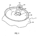
- Fig. 1 depicts one example of a container 112 having a marking 114 positioned on a container-opening tab.
- the tab 116 includes a covered or web area 118 in the central digit-grasping portion of the tab 116 and, in this embodiment, it is a portion of the web region 118 which bears the marking 114.
- Fig. 1 shows a configuration in which the tab 116 has been lifted 122 to a vertical position, revealing the underside of the tab (the surface visible in Fig. 1 ) and, in the process, forming an opening 124 in the can end 126.
- Fig. 1 shows a configuration in which the tab 116 has been lifted 122 to a vertical position, revealing the underside of the tab (the surface visible in Fig. 1 ) and, in the process, forming an opening 124 in the can end 126.
- the underside of the tab which is visible in Fig. 1 would normally be nonvisible prior to opening the container, i.e. would be maintained adjacent the outer (public) surface of the container end 126.
- the upper surface of the tab is not visible in the view of Fig. 1 but would be visible prior to opening the container. Accordingly, the embodiment of Fig. 1 can be used in connection with providing prize or other promotional indicia or other situations in which it is not desired or not necessary for the markings to be visible prior to opening the container.
- the present invention can be used in connection with marking other surfaces of the container including portions of the underside of the tab other than the central web 118, portions of the upper surface of the tab, portions of inner or outer surfaces of the container end 126 (and/or the opposite end, not shown in the partial view of Fig. 1 ), and/or inner or outer surfaces of the container body 128.
- the markings are provided in conjunction with a tab-forming process.
- tab-forming is accomplished by feeding a web of tab stock into a forming machine which uses well known metalworking procedures for forming the substantially flat tab stock into the desired tab shape. Examples of some of the metalworking procedures which may be used include stamping, coining, folding, cutting and the like. For economy of expression, references below to tab-stamping or tab-forming should be understood to include these and other well known tab-forming processes and machines.
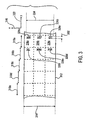
- the tab stock 312 has a width 314 (i.e. a lateral or x dimension 316) sufficient to form three tabs from a predetermined longitudinal length 318 a,b,c,d,e of tab stock 312 (i.e. a length along the longitudinal or y dimension 322).
- the tab stock 312 may have great longitudinal length, such as a web with a length of 3000 meters or more, the tab stock 312 is dimensioned, and in particular, has a width 314 such that each predetermined length 318a, 318e contains sufficient material to form a plurality of tabs, and in the depicted embodiment, sufficient material to form three tabs.
- predetermined length 318a can be used to form one tab from each of three laterally arranged regions 324 a,b,c.
- the tab stock 312 is fed or advanced to a tab-stamping device in an intermittent fashion. According to such intermittent feeding, the tab stock 312 is advanced longitudinally a distance equal to the predetermined distances 318 a,b,c,d,e during a first (or “advancement") period. Thereafter, the tab stock 312 is held substantially stationary for a second (or "dwell") period, during which stamping and other operations are performed on one or more predetermined lengths of the tab stock to form, e.g., three tabs.
- each cycle of the tab-stamping device includes an advancement period and a dwell period.
- stamping machine may be configured to have a plurality of stations or operations e.g. such that, during any one cycle, a first predetermined length 318 is undergoing a first operation, such as cutting, while preceding predetermined lengths 318b, 318c, 318d, etc. are undergoing other operations such as coining, folding, and the like.
- the tab-stamping cycles are relatively short such as defining a cycle time of less than about 150 milliseconds, preferably less than about 100 milliseconds, in at least one embodiment, a cycle time of about 87 milliseconds (equivalent to a stamping machine having 700 strokes per minute).
- the dwell time is about 2/3 of the cycle time and accordingly, the dwell time may be, e.g., about 100 milliseconds, preferably about 50 milliseconds or less.
- the desired markings are formed on the tab stock prior to reaching the stamping operations (i.e. the markings on any given region of the tab stock are formed before that region reaches the stamping device).
- the marking operation By configuring the marking operation in conjunction with the stamping operation, registering or positioning the markings on the tab stock so as to reside at the desired region of a finished tab is facilitated.
- the dwell time defines the length oftime (or "window") available for making the desired markings on any given predetermined length 318a, 318b, 318c, 318d, 318e of the tab stock 312.
- markings 326a-f are made on the tab stock 312 using laser light.
- the laser light is pulsed light, with each pulse being available for forming a single spot or dot such that a plurality of spots are positioned to, together, give the appearance or image of the desired characters or other markings.
- each pulse being available for forming a single spot or dot such that a plurality of spots are positioned to, together, give the appearance or image of the desired characters or other markings.
- the tab stock is formed of an alloy available under the trade designation 5042, e.g. from Aluminum Company of America or Kaiser Aluminium.
- the present invention is configured to achieve delivery of laser pulses, each with sufficient power to make a visible dot, sufficient in number to form the desired number and size of characters (with the desired quality or resolution) within the dwell time available for such marking considering any pulse non-application or blanking time e.g. used for accommodating relatively larger mirror movements such as movements between characters or between sets of characters.
- the device delivers pulses at a rate of about 12 kHz and produces at least 6, preferably at least nine characters of the desired quality with a character or letter height 332 of about 0.125 inches (about 3 mm) over a lateral range 334 of about 1 inch (about 2.5 cm).
- the present invention is also configured to position those dots, as needed, across an area of tab stock having a lateral extent 334 of about 1 inch and a longitudinal extent 332 of about 0.125 inches, i.e., over an area of about 0.125 square inches.
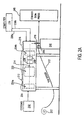
- Fig. 2A depicts one embodiment of an apparatus which can be used for making such markings within a time window of less than about 100 milliseconds, preferably less than about 50 milliseconds.
- a portion 212 of the device shown in Fig. 2A is used for generating a pulsed laser beam 214 which is then steered by a portion of the device 216 to output a laser beam 218 along a path so as to position pulses of the beam for forming markings 326 as described above.
- the laser includes a light source/pumping component 222 positioned between mirrors 224a,b to define a laser cavity.
- a safety valve 226 interrupts light output e.g. in the event of failure or container breach.
- a chopper 228 provides the light in a pulsed or intermittent form.
- a Nd:YAG laser provides an output of about 40 to 50 watts (applied power), with about 80% of such power being delivered to the tab stock target.
- the laser is configured to output laser light pulses which are relatively stable in the sense that there is relatively little variation in power from one pulse to the next and, preferably substantially all pulses have sufficient power to vaporize or ablate the metal target sufficiently to produce a visible spot or mark.
- Laser devices that can be used in this regard include those available from Lee Laser of Orlando, Florida.
- a cooling unit 232 is coupled 234 to the laser generation region 212 to maintain the proper operating temperature of the laser generating unit.
- a computer 236 which may be, e.g., a workstation-type computer preferably having a Pentium® or Pentium II® processor, outputs control signals 238a, 238b for controlling an x-steering galvanometer 242a and a y-steering galvanometer 242b, respectively, as described more fully below.
- galvanometers that can be used for this purpose includegalvanometers available Cambridge Technology, Inc. of Watertown, MA.
- the tab stock 312 is held at the desired distance from the laser and preferably in a vibration-free manner such as coupling guidance/advancement components 244 to a relatively vibration-free pedestal 246 such as a concrete-filled or other high-mass pedestal, vibration-isolation mounting or the like.
- the tab stock 312 can be held stationary during the dwell period for marking.
- the tab stock is advanced, using, e.g., drive rollers or the like, toward a stamping unit 248 as it is withdrawn from a tab stock coil 252 or similar source.
- the first steering galvanometer (e.g, a y-steering galvanometer 242a) is coupled to a movable, e.g., pivotable, mirror 254.
- Galvanometer 242a is coupled to the mirror 254 so that the mirror 254 is pivoted 256 about a pivot axis 258 (perpendicular to the plane ofthe paper in the view of Fig. 2B ) in such a manner that the mirror 254, receiving the laser pulses, will reflect the pulses (to provide first reflected laser light pulses) at an angle whose magnitude depends on the pivoted position of the mirror 254.
- the first reflected laser light pulses are received by the second mirror 260 which is coupled to a second galvanometer 242b (e.g., an x-steering galvanometer 242b) so as to permit selectable pivoting about a second pivot axis 262 (parallel to the plane of the paper in the view of Fig. 2B ) for reflecting the pulsed laser beam (to provide second reflected laser light pulses) toward the desired region of the tab stock 312.
- a second galvanometer 242b e.g., an x-steering galvanometer 242b
- the pivot position of the y-steering mirror 254 determines the position of the beam, (with respect to the tab stock 312) in a longitudinal or y direction 322 while pivoting of the x-steering mirror 260 about the second axis 262 determines the position of the laser pulses (with respect to the tab stock 312) in the lateral or x direction 316.
- the mirrors 254, 260, and particularly the x-steering mirror 260 (responsible for positioning through the relatively larger x range) must be moved quite rapidly. It is believed that previous steering devices have been incapable of, at a reasonable cost, providing such rapid mirror positioning. According to one embodiment of the present invention, rapid mirror positioning is facilitated by providing relatively low mass mirrors.
- the mirrors in one embodiment, are provided in a lightweight configuration primarily by providing a relatively small surface or reflective area of the mirrors.
- the mirrors have a nominal size or diameter of about 5 mm, such as being a square or rectangle with at least one edge having a length less than or equal to about 5 mm.
- the low mass mirrors provide a low moment of inertia to assist in rapid mirror movement.
- each of the mirrors presents a moment of inertia to the respective galvanometers of less than about 0.2 g/cm 2 , preferably less than about 0.1 g / cm 2 , and more preferably less than or equal to about 0.08 g / cm 2 .
- the diameter of the beam upon reaching the tab stock 312 is less than about 5 mm in diameter, preferably less than about 3 mm in diameter.
- the computer 236 is configured (programmed) to output control signals to achieve the desired positioning at this rate as well as being controlled to retrieve, create or select the desired characters or indicia 326a-326d as needed for the particular application (e.g. random or pseudo-random indicia for certain contest or promotion purposes) and to make the character or indicia selections rapidly enough to provide a new set of selections during each cycle of the stamping device 248.
- the tab stock 312 is positioned such that the spot size ofthe laser pulses as delivered to this tab stock has a diameter of about 3 mm and a power density of about 4 to 5 watts per mm 2 .
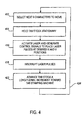
- the computer 236 selects the next nine characters which are to be marked on the tab stock 412.
- the tab stock is held stationary 414 and the laser light output is activated while the computer generates control signals to place laser pulses at the desired respective x and y positions to render the desired visible markings 416.
- the laser pulses are interrupted 418 and, during the advancement portion of the cycle, the tab stock is advanced a predetermined longitudinal increment toward the stamping machine. Thereafter, the cycle is repeated 424 as needed to provide the desired number of marked tabs or until the tab stock is depleted.
- the present invention is able to achieve markings of containers or container components at a relatively rapid rate, and, preferably, sufficiently rapidly to keep pace with other container or container component forming processes so that the marking can be achieved without slowing or interfering with such processes.
- the present invention makes it practical and feasible to provide markings which can be readily changed or customized, including markings which are different for each container or container component in a sequence of containers or components.
- the present invention can achieve such rapid markings substantially without distortion or deformation of the markings and without weakening, piercing or damaging the container or container component.
- the present invention makes it practical and feasible to provide six or more, preferably nine or more, legible, 0.125 inches tall or larger characters distributed or positioned across the width of tab stock in connection with a tab-forming process during a relatively short time period such as a tab-forming dwell time, preferably within about 100 milliseconds and more preferably within about 50 milliseconds.
- the present invention makes it possible to steer the positioning of laser pulses having sufficient power to mark or ablate metal across a lateral extent of about one inch and a longitudinal extent of about 125 inches within a time period of less than 100 milliseconds, preferably less than about 50 milliseconds.
- the present invention provides for container or container component marking which is less maintenance-intensive or more reliable than other marking procedures and devices and permits changes to markings without the need to stop or slow a container or container component fabrication device or process.
- the present invention facilitates implementation of contests, sweepstakes or other promotions which involve providing indicia on components or containers preferably on an undersurface of tabs coupled to containers, preferably so as to be non-visible prior to opening a container, e.g. awarding at least a first prize (indicated one of such indicia) to a customer upon verifying presence of the prize indicium e.g. on a tab. Because the characters, indicia, symbols and the like to be marked can be designed/created entirely (potentially) in software (i.e.
- the lead time involved between design of a promotion, game, or the like, taking of an order or other initiation event, and the time in which production can begin is substantially shortened compared to hardware-dependent procedures such as incising or embossing.
- the present invention provides for a cost-effective procedure and device which may include a laser that delivers sufficiently-powered pulses at a rate of about 12 kHz
- a cost-effective procedure and device which may include a laser that delivers sufficiently-powered pulses at a rate of about 12 kHz
- other lasers including lasers that have a higher pulse rate or higher power, preferably with each (or substantially each) pulse delivering sufficient power to ablate or vaporize aluminum or other metal such as to provide a visible mark.
- a galvanometer-based beam steering procedure and device has been described, other steering may be used including acoustico-optical steering in place of or in addition to galvanometer based steering, which offers the potential for steering which is at least partially independent ofthe mass of mirrors or other components and, thus, potentially more rapid.
- DSP digital signal processors
- the present invention can be used in connection with a wide variety of metal containers including beverage containers, food containers, aerosol containers and the like.
- the present invention has been described in connection with marking of aluminum container or container components, the present invention can also be used in connection with marking other types of metal containers such as steel containers.
- the present invention has been described in connection with ablating or vaporizing portions of the metal of a metal container, it is also possible to use the present invention in connection with ablating or vaporizing some or all portions of coatings placed on a metal container, so as to provide markings that are visible by way of a contrasting color or texture.
- a metal container or container component which has been coated with a colored coating (such as by printing or painting) and to use the present invention to selectively remove or vaporize portions of such coatings to reveal at least some of the metal portion (or another coating) underneath.
- a lower-powered laser such as a CO 2 laser.
- Fig. 1 depicts a tab having a web in the finger grasp region
- the present invention in connection with a tab in which a finger hole is provided in the finger grasp region and in which markings are positioned on other portions of the tab.
- the present invention has been described in connection with certain markings which will typically be viewed or visible to consumers such as promotional or contest marking, advertising, logos, etc., it is also possible to use the present invention in connection with markings which will typically be concealed such as being concealed under a fold of the tab or other container component.
- markings which will typically be concealed such as being concealed under a fold of the tab or other container component.
- concealed markings may be used for security or verification purposes, e.g. to verify that a prize-indicating marking is genuine and not counterfeit.
- the present invention has been described in connection with beam steering which utilizes two separate mirrors, it is possible to provide for beam steering which uses a single mirror (e.g. which is pivotable with respect to two independently controllable axes, and/or which is deflectable or deformable).
- a single mirror e.g. which is pivotable with respect to two independently controllable axes, and/or which is deflectable or deformable.
- the present invention has been described in connection with a process which uses a single laser for writing all the desired markings during any given cycle (believed to be particularly useful when it is desired to provide markings in a low-cost manner), it is nevertheless also possible to use the present invention in connection with a system having two or more lasers such as for writing different characters or different portions of characters so as to achieve a higher number of characters in a given amount of time.
- the present invention has been described in connection with a procedure providing at least six legible characters, preferably at least nine legible characters per cycle, the present invention can also be used in connection
- the present invention can be used to provide markings which indicate time and/or date of manufacture, filling, sealing and the like.
- marking tabs e.g. after folding but before cutting, after cutting but before attachment to containers, or after attachment to containers.
Abstract
Description
- The present invention relates to method of marking and forming metallic containers including container body end tab portions and in particular to process that can rapidly achieve the desired amount of marking within a predetermined time such as a manufacturing process dwell time. The present invention relates also to an apparatus for forming and marking components for containers.
- As part of a container manufacturing, or in some cases, filling or sealing operation, markings may be placed on containers for a variety of purposes including identifying contents, identifying the location or date of manufacture or use, identifying the maker of the container or container component, the style or materials for the container, providing of trade names, advertising, promotion, or the like. In some situations, promotional information in the form of sweepstakes, contests, or other valuable tokens or indicia are placed or marked on container or container components.
- A variety of devices and procedures have been used for marking containers. In some cases, embossing or incising processes have been used. Embossing or incising, e.g. via stamping, can require an undesirably large inventory oftools, e.g. for different kinds of lettering or symbols, and typically requires the need to shut down an assembly line and disassemble a press whenever it is desired to change tools (such as for changing the indicia being incised or embossed or for maintenance or repair purposes). Such shutdowns are particularly troublesome when it is desirable to change the symbols with, relatively high frequency, such as when markings on containers are intended as part of a contest or sweepstakes in which there are preferably a relatively large number of different possible markings or indicia (e.g. when only some of which are "grand prize" winners). Furthermore, it has been difficult to accurately control the depth of embossing or incising and, in some cases, embossing or incising that is too deep has led to leakage or container failure.
- Accordingly, it would be advantageous to provide for marking of containers or components in a fashion permitting markings or indicia to be changed with relatively high frequency but without the need to stop or slow down a production line for this purpose. It would also be useful to provide for marking containers while avoiding the need for maintaining relatively large inventories of tools or dies, and preferably while avoiding container quality problems such as may arise from markings which are excessively deep.
- Another process which has been used for placing markings on containers or components thereof, has been one or more printing processes. Contact or press printing is sometimes useful for decorating or placing markings on containers where it is desired to place a relatively large number of identical markings on containers. However, contact printing is believed impractical for many components, because of their shape or position (such as container-opening tabs) or when it is desired to change indicia with relatively high frequency (e.g. for sweepstake or contest purposes) because of the need to stop a production line and partially disassemble the contact print device in order to change the configuration of the items being printed on the containers.
- In some situations, components of containers may be printed using a non-contact printing process such as an inkjet process. Although inlets can be controlled to provide relatively frequent changes in indicia, inkjet processes and equipment have been found, in the past, to be relatively unreliable such as requiring frequent maintenance and repair. Inkjet processes have also been found to be subject to unwanted placement or positioning of ink such as resulting in a mist of ink which can interfere with the printing process, cause undesired markings on cans, or cause equipment malfunction. In some cases, it has been found that up to 20% or more of potential production time has been lost to the need for cleaning up, maintenance and/or repair when an ink jet process is used. Additionally, it has been found difficult to achieve reliable adhesion of the ink to containers or container components. Furthermore, when inkjet or other printing processes are used in connection with contest sweepstakes or providing other valuable tokens or indicia, since the process provides only surface markings (without forming indentations e.g. in the container itself) there is an undesirably large potential for counterfeiting or altering the markings e.g. in an attempt to claim a contest or sweepstakes prize. Furthermore, inkjet processes have been difficult to provide at high speed while maintaining quality, so as to mark letters or other indicia without distortion or the like.
-
US-A-5 511 920 discloses an apparatus for forming tabs for containers, with a forming station for attaining the tabs. It includes also a driving means for moving the tabs to the assembly line.W0-A-97/11892 - Accordingly, it would be useful to provide for high quality marking of containers or container components while avoiding the cleanup, maintenance and repair time associated with inkjet or other printing processes, preferably while permitting relatively rapid changes of indicia.
- Some or all of the above difficulties in previous container marking procedures are particularly troublesome for metallic containers or container components such as a typical aluminum alloy beverage container (e.g. of the type available from Ball Corporation, Broomfield, Colorado) or tabs or other components thereof. As compared with, e.g., plastic containers or container components, metal containers can be relatively difficult to mark, at least because it can be difficult to adhere ink to metal surfaces, because of the harder surface of metal containers, higher melting or softening point, and the like. Accordingly, devices and processes used in connection with some container materials are not necessarily applicable to others. In most situations, the functions or purposes for container markings will rarely justify use of procedures which would involve expenses which are substantially in excess of those involved with current processes. Accordingly, it would be useful to provide for procedures and devices for marking containers which can be achieved economically, preferably without substantially exceeding costs or expenses associated with current container production, filling or sealing processes.
- The present invention provides a method of marking and forming metal containers or container components (including, e.g., container bodies, container ends and container end tabs) according to claim 1. A laser is provided with rapid-acting beam-steering and control to permit the marking of a relatively large number of characters or symbols (such as 6 or more, preferably 9 or more) in a relatively short period of time less than about 100 milliseconds (preferably less than a normal component production dwell time e.g. of about 50 milliseconds) so that the desired marking can be achieved without stopping or slowing current container or container component fabrication procedures or machines. The present invention relates also to an apparatus for forming and marking components for containers according to claim 6.
- In one embodiment, steering of a laser beam is achieved with high rapidity by reducing the mass ofone or more steering mirrors. The resultant device delivers sufficient power density to form visible marks in a metal (e.g. aluminum) container component despite the decreased beam size or aperture associated with the smaller mirror size.
- Preferably, the laser light is delivered to the container region or component as a series of high intensity laser pulses. Each pulse forms a visible ablated area or dot and the pattern of dots together make up the desired symbol or image. Accordingly, to achieve a desired number of characters or symbols in less than a predetermined period of time, the device must be capable of delivering all of the pulses needed for forming all of the desired characters within the predetermined time period. In one embodiment, a laser device is provided which delivers pulses at a frequency of at least about 12 kiloHertz (kHz) while providing sufficient power that substantially all such pulses produce the desired spot ablation of the metal container component.
-
-
Fig. 1 is a partial perspective view of a container end with a tab marked according to an embodiment of the present invention; -
Fig. 2A is a block diagram depicting components of a container tab stock marking device according to an embodiment of the present invention; -
Fig. 2B is a block diagram of steering components of the device ofFig. 2A ; -
Fig. 3 is a partial plan view of partially-marked tab stock according to an embodiment of the present invention; and -
Fig. 4 is a flow chart depicting a marking process according to an embodiment of the present invention. - Although the present invention can be used in marking many portions of a container or a container component and marking many shapes and styles of containers,
Fig. 1 depicts one example of a container 112 having a marking 114 positioned on a container-opening tab. In the depicted embodiment, thetab 116 includes a covered orweb area 118 in the central digit-grasping portion of thetab 116 and, in this embodiment, it is a portion of theweb region 118 which bears the marking 114.Fig. 1 shows a configuration in which thetab 116 has been lifted 122 to a vertical position, revealing the underside of the tab (the surface visible inFig. 1 ) and, in the process, forming anopening 124 in the can end 126. In the embodiment ofFig. 1 , the underside of the tab which is visible inFig. 1 would normally be nonvisible prior to opening the container, i.e. would be maintained adjacent the outer (public) surface of thecontainer end 126. The upper surface of the tab is not visible in the view ofFig. 1 but would be visible prior to opening the container. Accordingly, the embodiment ofFig. 1 can be used in connection with providing prize or other promotional indicia or other situations in which it is not desired or not necessary for the markings to be visible prior to opening the container. The present invention, however, can be used in connection with marking other surfaces of the container including portions of the underside of the tab other than thecentral web 118, portions of the upper surface of the tab, portions of inner or outer surfaces of the container end 126 (and/or the opposite end, not shown in the partial view ofFig. 1 ), and/or inner or outer surfaces of thecontainer body 128. - When it is desired to provide markings on one or more regions of a container-opening
tab 116, the markings, in one embodiment, are provided in conjunction with a tab-forming process. In many situations, tab-forming is accomplished by feeding a web of tab stock into a forming machine which uses well known metalworking procedures for forming the substantially flat tab stock into the desired tab shape. Examples of some of the metalworking procedures which may be used include stamping, coining, folding, cutting and the like. For economy of expression, references below to tab-stamping or tab-forming should be understood to include these and other well known tab-forming processes and machines. - As depicted in
Fig. 3 , in one embodiment thetab stock 312 has a width 314 (i.e. a lateral or x dimension 316) sufficient to form three tabs from a predeterminedlongitudinal length 318 a,b,c,d,e of tab stock 312 (i.e. a length along the longitudinal or y dimension 322). Although thetab stock 312 may have great longitudinal length, such as a web with a length of 3000 meters or more, thetab stock 312 is dimensioned, and in particular, has awidth 314 such that eachpredetermined length length 318a can be used to form one tab from each of three laterally arrangedregions 324 a,b,c. - In one configuration, the
tab stock 312 is fed or advanced to a tab-stamping device in an intermittent fashion. According to such intermittent feeding, thetab stock 312 is advanced longitudinally a distance equal to thepredetermined distances 318 a,b,c,d,e during a first (or "advancement") period. Thereafter, thetab stock 312 is held substantially stationary for a second (or "dwell") period, during which stamping and other operations are performed on one or more predetermined lengths of the tab stock to form, e.g., three tabs. Thus, each cycle of the tab-stamping device includes an advancement period and a dwell period. These cycles are repeated, one after another, preferably forming a plurality of tabs (such as three tabs) at each cycle or stroke of the stamping machine. It should be understood that the stamping machine may be configured to have a plurality of stations or operations e.g. such that, during any one cycle, a first predetermined length 318 is undergoing a first operation, such as cutting, while precedingpredetermined lengths - Preferably, the tab-stamping cycles are relatively short such as defining a cycle time of less than about 150 milliseconds, preferably less than about 100 milliseconds, in at least one embodiment, a cycle time of about 87 milliseconds (equivalent to a stamping machine having 700 strokes per minute). In one embodiment, the dwell time is about 2/3 of the cycle time and accordingly, the dwell time may be, e.g., about 100 milliseconds, preferably about 50 milliseconds or less.
- In one embodiment, the desired markings are formed on the tab stock prior to reaching the stamping operations (i.e. the markings on any given region of the tab stock are formed before that region reaches the stamping device). By configuring the marking operation in conjunction with the stamping operation, registering or positioning the markings on the tab stock so as to reside at the desired region of a finished tab is facilitated.
- In order to avoid distortion of the markings that might otherwise be associated with the relatively high acceleration curves used during the advancement phase of the cycle, it is preferred to achieve at least some, and, preferably substantially all of the marking during the stationary or dwell phase of each cycle. Accordingly, in this embodiment, the dwell time defines the length oftime (or "window") available for making the desired markings on any given
predetermined length tab stock 312. According to the present invention,markings 326a-f are made on thetab stock 312 using laser light. Preferably the laser light is pulsed light, with each pulse being available for forming a single spot or dot such that a plurality of spots are positioned to, together, give the appearance or image of the desired characters or other markings. For example, for aluminum alloys typically used for tab stock, it is believed that delivering laser pulses with a power density of at least about 4 - 5 watts per mm2 will suffice to deliver sufficient power to achieve the ablation of aluminum necessary to provide visible spots. In one embodiment, the tab stock is formed of an alloy available under the trade designation 5042, e.g. from Aluminum Company of America or Kaiser Aluminium. Accordingly, the present invention is configured to achieve delivery of laser pulses, each with sufficient power to make a visible dot, sufficient in number to form the desired number and size of characters (with the desired quality or resolution) within the dwell time available for such marking considering any pulse non-application or blanking time e.g. used for accommodating relatively larger mirror movements such as movements between characters or between sets of characters. - In one embodiment, the device delivers pulses at a rate of about 12 kHz and produces at least 6, preferably at least nine characters of the desired quality with a character or
letter height 332 of about 0.125 inches (about 3 mm) over alateral range 334 of about 1 inch (about 2.5 cm). - Thus, in addition to providing a sufficient number of dots within the time window to form the desired size and quality of characters, the present invention is also configured to position those dots, as needed, across an area of tab stock having a
lateral extent 334 of about 1 inch and alongitudinal extent 332 of about 0.125 inches, i.e., over an area of about 0.125 square inches. -
Fig. 2A depicts one embodiment of an apparatus which can be used for making such markings within a time window of less than about 100 milliseconds, preferably less than about 50 milliseconds. Aportion 212 of the device shown inFig. 2A is used for generating apulsed laser beam 214 which is then steered by a portion of thedevice 216 to output alaser beam 218 along a path so as to position pulses of the beam for forming markings 326 as described above. The laser includes a light source/pumping component 222 positioned betweenmirrors 224a,b to define a laser cavity. Preferably asafety valve 226 interrupts light output e.g. in the event of failure or container breach. Achopper 228 provides the light in a pulsed or intermittent form. In one embodiment, a Nd:YAG laser provides an output of about 40 to 50 watts (applied power), with about 80% of such power being delivered to the tab stock target. Preferably the laser is configured to output laser light pulses which are relatively stable in the sense that there is relatively little variation in power from one pulse to the next and, preferably substantially all pulses have sufficient power to vaporize or ablate the metal target sufficiently to produce a visible spot or mark. Laser devices that can be used in this regard include those available from Lee Laser of Orlando, Florida. Acooling unit 232 is coupled 234 to thelaser generation region 212 to maintain the proper operating temperature of the laser generating unit. Acomputer 236 which may be, e.g., a workstation-type computer preferably having a Pentium® or Pentium II® processor, outputscontrol signals x-steering galvanometer 242a and a y-steeringgalvanometer 242b, respectively, as described more fully below. One example of galvanometers that can be used for this purpose includegalvanometers available Cambridge Technology, Inc. of Watertown, MA. Thetab stock 312 is held at the desired distance from the laser and preferably in a vibration-free manner such as coupling guidance/advancement components 244 to a relatively vibration-free pedestal 246 such as a concrete-filled or other high-mass pedestal, vibration-isolation mounting or the like. In this way, a portion of thetab stock 312 can be held stationary during the dwell period for marking. As described above, during the advancement period of each cycle, the tab stock is advanced, using, e.g., drive rollers or the like, toward astamping unit 248 as it is withdrawn from atab stock coil 252 or similar source. - In the embodiment of
Fig. 2B , the first steering galvanometer (e.g, a y-steering galvanometer 242a) is coupled to a movable, e.g., pivotable,mirror 254.Galvanometer 242a is coupled to themirror 254 so that themirror 254 is pivoted 256 about a pivot axis 258 (perpendicular to the plane ofthe paper in the view ofFig. 2B ) in such a manner that themirror 254, receiving the laser pulses, will reflect the pulses (to provide first reflected laser light pulses) at an angle whose magnitude depends on the pivoted position of themirror 254. The first reflected laser light pulses are received by thesecond mirror 260 which is coupled to asecond galvanometer 242b (e.g., anx-steering galvanometer 242b) so as to permit selectable pivoting about a second pivot axis 262 (parallel to the plane of the paper in the view ofFig. 2B ) for reflecting the pulsed laser beam (to provide second reflected laser light pulses) toward the desired region of thetab stock 312. In the view ofFig. 2B , the pivot position of the y-steering mirror 254 determines the position of the beam, (with respect to the tab stock 312) in a longitudinal ory direction 322 while pivoting of thex-steering mirror 260 about thesecond axis 262 determines the position of the laser pulses (with respect to the tab stock 312) in the lateral or xdirection 316. - In order to position the laser pulses as needed across the entire
lateral extent 334 andlongitudinal extent 332 needed to form a set ofcharacters mirrors - Because the reflective surface area ofthe steering mirrors is reduced, the beam size or aperture of the laser light which can be effectively delivered to the tab stock is relatively small. In one embodiment the diameter of the beam upon reaching the
tab stock 312 is less than about 5 mm in diameter, preferably less than about 3 mm in diameter. - In order to position the laser pulses, which are preferably being delivered at a rate of about 12kHz, to the desired position, it is necessary to provide x and
y control signals galvanometers computer 236 is configured (programmed) to output control signals to achieve the desired positioning at this rate as well as being controlled to retrieve, create or select the desired characters orindicia 326a-326d as needed for the particular application (e.g. random or pseudo-random indicia for certain contest or promotion purposes) and to make the character or indicia selections rapidly enough to provide a new set of selections during each cycle of thestamping device 248. Although it is at least theoretically possible to increase thelateral range 334 orlongitudinal range 332 of the beam position by increasing the distance e.g. of thetab stock 312 from one or both mirrors, such increase in distance also increases the effect of beam divergence and, thus affects power density delivered at the tab stock. For example, by decreasing divergence by 50% (e.g. by positioning the tab stock closer), spot size at the tab stock is reduced to half the spot diameter, thus halving the power delivered, but, because area is proportional to the square of radius, doubling the power density. However, increasing power density by providing for closer positioning of the tab stock requires more rapid mirror movements to maintain the same marking speed (for a given range of character placement). Thus, in one embodiment, thetab stock 312 is positioned such that the spot size ofthe laser pulses as delivered to this tab stock has a diameter of about 3 mm and a power density of about 4 to 5 watts per mm2. - In operation, as depicted in
Fig. 4 , during one portion of the stamping cycle, thecomputer 236 selects the next nine characters which are to be marked on thetab stock 412. When the dwell period of the stamping cycle is reached, the tab stock is held stationary 414 and the laser light output is activated while the computer generates control signals to place laser pulses at the desired respective x and y positions to render the desiredvisible markings 416. Afterthe desired markings have been made, the laser pulses are interrupted 418 and, during the advancement portion of the cycle, the tab stock is advanced a predetermined longitudinal increment toward the stamping machine. Thereafter, the cycle is repeated 424 as needed to provide the desired number of marked tabs or until the tab stock is depleted. - In light of the information provided herein, a number of advantages can be seen. The present invention is able to achieve markings of containers or container components at a relatively rapid rate, and, preferably, sufficiently rapidly to keep pace with other container or container component forming processes so that the marking can be achieved without slowing or interfering with such processes. The present invention makes it practical and feasible to provide markings which can be readily changed or customized, including markings which are different for each container or container component in a sequence of containers or components. The present invention can achieve such rapid markings substantially without distortion or deformation of the markings and without weakening, piercing or damaging the container or container component. The present invention makes it practical and feasible to provide six or more, preferably nine or more, legible, 0.125 inches tall or larger characters distributed or positioned across the width of tab stock in connection with a tab-forming process during a relatively short time period such as a tab-forming dwell time, preferably within about 100 milliseconds and more preferably within about 50 milliseconds. The present invention makes it possible to steer the positioning of laser pulses having sufficient power to mark or ablate metal across a lateral extent of about one inch and a longitudinal extent of about 125 inches within a time period of less than 100 milliseconds, preferably less than about 50 milliseconds. The present invention provides for container or container component marking which is less maintenance-intensive or more reliable than other marking procedures and devices and permits changes to markings without the need to stop or slow a container or container component fabrication device or process. The present invention facilitates implementation of contests, sweepstakes or other promotions which involve providing indicia on components or containers preferably on an undersurface of tabs coupled to containers, preferably so as to be non-visible prior to opening a container, e.g. awarding at least a first prize (indicated one of such indicia) to a customer upon verifying presence of the prize indicium e.g. on a tab. Because the characters, indicia, symbols and the like to be marked can be designed/created entirely (potentially) in software (i.e. without the need for ordering or creating dies or the like) the lead time involved between design of a promotion, game, or the like, taking of an order or other initiation event, and the time in which production can begin is substantially shortened compared to hardware-dependent procedures such as incising or embossing.
- A number of variations and modifications of the invention can be used. Although the present invention provides for a cost-effective procedure and device which may include a laser that delivers sufficiently-powered pulses at a rate of about 12 kHz, it is also possible to use the present invention in connection with other lasers, including lasers that have a higher pulse rate or higher power, preferably with each (or substantially each) pulse delivering sufficient power to ablate or vaporize aluminum or other metal such as to provide a visible mark. Although a galvanometer-based beam steering procedure and device has been described, other steering may be used including acoustico-optical steering in place of or in addition to galvanometer based steering, which offers the potential for steering which is at least partially independent ofthe mass of mirrors or other components and, thus, potentially more rapid. Although a computer has been described. in connection with providing control or control signals for laser steering, other devices and procedures for providing control signals can be used including digital signal processors (DSP) which are believed to offer the potential for generating control signals at a relatively high rate, at least partially because of the elimination or reduction of rate dependency based on bus speed or the like.
- Although embodiments have been described in regard to marking of stock used for forming tabs, the present invention can be used in connection with marking other portions of metal containers such as ends or end caps, body or sidewall portions, container bottom portions and the like.
- Although a particular container end shape as depicted in
Fig. 1 , the present invention can be used in connection with a wide variety of metal containers including beverage containers, food containers, aerosol containers and the like. Although the present invention has been described in connection with marking of aluminum container or container components, the present invention can also be used in connection with marking other types of metal containers such as steel containers. Although the present invention has been described in connection with ablating or vaporizing portions of the metal of a metal container, it is also possible to use the present invention in connection with ablating or vaporizing some or all portions of coatings placed on a metal container, so as to provide markings that are visible by way of a contrasting color or texture. For example, it is possible to provide a metal container or container component which has been coated with a colored coating (such as by printing or painting) and to use the present invention to selectively remove or vaporize portions of such coatings to reveal at least some of the metal portion (or another coating) underneath. In this situation, it may be possible to use a lower-powered laser such as a CO2 laser. - Although the embodiment of
Fig. 1 depicts a tab having a web in the finger grasp region, it is also possible to use the present invention in connection with a tab in which a finger hole is provided in the finger grasp region and in which markings are positioned on other portions of the tab. - Although the present invention has been described in connection with certain markings which will typically be viewed or visible to consumers such as promotional or contest marking, advertising, logos, etc., it is also possible to use the present invention in connection with markings which will typically be concealed such as being concealed under a fold of the tab or other container component. As one example, concealed markings may be used for security or verification purposes, e.g. to verify that a prize-indicating marking is genuine and not counterfeit.
- Although the present invention has been described in connection with beam steering which utilizes two separate mirrors, it is possible to provide for beam steering which uses a single mirror (e.g. which is pivotable with respect to two independently controllable axes, and/or which is deflectable or deformable). Although the present invention has been described in connection with a process which uses a single laser for writing all the desired markings during any given cycle (believed to be particularly useful when it is desired to provide markings in a low-cost manner), it is nevertheless also possible to use the present invention in connection with a system having two or more lasers such as for writing different characters or different portions of characters so as to achieve a higher number of characters in a given amount of time. Although the present invention has been described in connection with a procedure providing at least six legible characters, preferably at least nine legible characters per cycle, the present invention can also be used in connection with devices or procedures which produce more or fewer characters.
- In general, it is possible to use some aspects ofthe invention without using others. For example, it is possible to provide for rapid marking of characters or other indicia without providing for randomly or otherwise changing the indicia with each cycle. For example, in view of the ability to rapidly change or modify the nature of the indicia or markings provided, the present invention can be used to provide markings which indicate time and/or date of manufacture, filling, sealing and the like. Although the present invention has been described in connection with placing markings on tab stock before the tab stock is formed, cut or attached to containers or container ends, it is possible to provide the steps in other orders such as marking tabs e.g. after folding but before cutting, after cutting but before attachment to containers, or after attachment to containers.
- The foregoing discussion of the invention has been presented for purposes of illustration and description. The foregoing is not intended to limit. the invention to the form or forms disclosed herein. Although the description of the invention has included description of one or more embodiments and certain variations and modifications, other variations and modifications are within the scope of the invention as defined in the appended claims.
Claims (9)
- a method of marking and forming metallic containers (112) having selectable pattern defining-characters thereon, each container being formed from a container body (128) and a container end (126), the method comprising the following steps:a. driving at least one component (116) of at least one metallic container (112) and at least another, component (116) of at least another metallic container (112) to respectively a laser marking station and a forming station, wherein the components are either the container bodies (128), the container ends (126) or tabstock (116) to be incorporated into the container bodies or the container ends by attachment.b. during a dwell time of a cycle of operation being less than 100 milliseconds, within which the at least one component (116) of the at least one container and the at least another component (116) of the at least another container are substantially stationary in respectively the laser marking station and in the forming station, controlling a laser source,(222), of the laser marking station so to ablate desired regions of the at least one component of the at least one metallic container and then marking with the laser beam produced by the laser source (222) a relatively large number of characters to form selectable patterns on a desired region of the at least one component of the at least one container, the marking being achieved by moving at least one movable mirror (254,260) having low inertia along the at least one component of the at least once container, while altering the at least another component of the at least another container by a forming operation in the forming station, the forming operation including one of cutting, coining and folding.
- A method as claimed in Claim 1, wherein the at least one component is the portion (116) to be incorporated into the container end (126) and includes one container-opening tab (116), wherein the desired region is on the tab (116), and wherein the laser ablation takes place prior to incorporation of the tab (116) into the container end (126) .
- A method as claimed in Claim 2, wherein there are a plurality of tabs (116) including the one tab (116) that is formed from a tab stock (312) feed, and wherein a set of tabs (116) is formed across the width of the tab stock (312) feed, the number of tabs (116) in each set being more than 1, and wherein the at least nine said characters for the tabs (116) in a said set of tabs are produced by the laser source (222) within a period of 150 milliseconds after providing all the selectable patterns on the preceding set of tabs.
- A method as claimed in Claim 3, wherein the number of tabs (116) in each set is at least three.
- A method as claimed in Claim 1 wherein the time taken to produce a subsequent set of at least nine characters by said laser source (222) after the production of a preceding set of at least nine characters is less than about 150 milliseconds, and wherein characters can be selected to be different in subsequent sets of characters.
- Apparatus for forming and marking components (116) for containers, the apparatus comprising:a. a laser marking station comprising a laser system (212) for outputting laser light (214), a light path deflection system (216) configured to receive laser light (214) and position laser light (218) along a path toward at least one component (116) of at least one container (112) on which markings are made, said light path deflection system including at least one movable mirror (254, 260) that is movable through an angle at least sufficient to position said markings across a lateral range of at least 1 inch (2.54 cm)b. a forming station for altering by a forming operation at least one component of at least another component (116), the forming operation including one of cutting, coining and foldingc. a drive for moving one component of one container from the laser marking station to the forming stationd. wherein, in use, the apparatus for forming and marking has a dwell time of a cycle of operations of less than 100 milliseconds and, during said dwell time of the cycle of operations, each of the at least one component of the at least one container and the at least another component of the at least another container are substantially stationary and wherein the apparatus permits the marking of the at least one component of the at least one container with a relatively large number of characters in the laser marking station while at least one component of the at least another container is altered by the forming operation in the forming station.
- Apparatus as claimed in Claim 6 further comprising means for controlling (238a, 238b, 242a, 242b) positioning of said at least one mirror (254, 260) to a sequential plurality of positions wherein at least two of said sequential plurality of positions occur less than about .01 millisecond apart.
- Apparatus as claimed in Claim 6 wherein said light path deflection system (216) comprises: a galvanometer (242a) coupled to said at least one mirror (254) to position said at least one mirror (254), in response to a first control signal (238a), to reflect laser light (218) along a first reflected path toward a second mirror (260), wherein said second mirror (260) has a nominal dimension of no more than about 5mm; and a galvanometer (242b) coupled to said second mirror (260) to position said second mirror (260), in response to a second control signal (238b), to reflect laser light (218) along a second reflected path toward said marking station (244,246).
- Apparatus as claimed in Claim 6 wherein said light path deflection system (216) comprises a galvanometer (242a, 242b) and in which said at least one mirror (254, 260) presents a moment of inertia to said galvanometer (242a, 242b) of less than 0.2 g/cm2.
Applications Claiming Priority (3)
| Application Number | Priority Date | Filing Date | Title |
|---|---|---|---|
| US09/116,794 US6080958A (en) | 1998-07-16 | 1998-07-16 | Method and apparatus for marking containers using laser light |
| US116794 | 1998-07-16 | ||
| PCT/US1999/015990 WO2000003832A1 (en) | 1998-07-16 | 1999-07-15 | Method and apparatus for marking containers using laser light |
Publications (4)
| Publication Number | Publication Date |
|---|---|
| EP1113901A1 EP1113901A1 (en) | 2001-07-11 |
| EP1113901A4 EP1113901A4 (en) | 2002-10-09 |
| EP1113901B1 EP1113901B1 (en) | 2005-01-19 |
| EP1113901B2 true EP1113901B2 (en) | 2008-08-27 |
Family
ID=22369268
Family Applications (1)
| Application Number | Title | Priority Date | Filing Date |
|---|---|---|---|
| EP99937259A Expired - Lifetime EP1113901B2 (en) | 1998-07-16 | 1999-07-15 | Method and apparatus for marking containers using laser light |
Country Status (10)
| Country | Link |
|---|---|
| US (4) | US6080958A (en) |
| EP (1) | EP1113901B2 (en) |
| JP (1) | JP2002520164A (en) |
| CN (1) | CN1313801A (en) |
| AT (1) | ATE287312T1 (en) |
| AU (1) | AU761807B2 (en) |
| DE (1) | DE69923329T3 (en) |
| DK (1) | DK1113901T3 (en) |
| ES (1) | ES2237134T3 (en) |
| WO (1) | WO2000003832A1 (en) |
Families Citing this family (50)
| Publication number | Priority date | Publication date | Assignee | Title |
|---|---|---|---|---|
| US6926487B1 (en) | 1998-04-28 | 2005-08-09 | Rexam Ab | Method and apparatus for manufacturing marked articles to be included in cans |
| GB2347370B (en) * | 1999-02-12 | 2002-10-30 | American Nat Can Co | Method and apparatus for printing |
| US6479787B1 (en) | 1999-10-05 | 2002-11-12 | Rexam Ab | Laser unit and method for engraving articles to be included in cans |
| US6780012B1 (en) * | 1999-12-20 | 2004-08-24 | 3M Innovative Properties Company | Article with laser engraved identification mark |
| US6872913B1 (en) | 2000-01-14 | 2005-03-29 | Rexam Ab | Marking of articles to be included in cans |
| US6455806B1 (en) | 2000-01-14 | 2002-09-24 | Rexam Ab | Arrangement for shaping and marking a target |
| US6926456B1 (en) | 2000-01-20 | 2005-08-09 | Rexam Ab | Guiding device for a marking arrangement |
| BE1014393A3 (en) * | 2000-03-13 | 2003-10-07 | Stasiuk Joseph W | Container opening device consisting of a laser etched pull tab engraved with product information. |
| AU2006202191B2 (en) * | 2000-03-13 | 2010-10-14 | Stasiuk, Joseph W | Laser-etched pull tab container opening devices and methods of making the same |
| US6576871B1 (en) | 2000-04-03 | 2003-06-10 | Rexam Ab | Method and device for dust protection in a laser processing apparatus |
| US6515256B1 (en) * | 2000-04-13 | 2003-02-04 | Vincent P. Battaglia | Process for laser machining continuous metal strip |
| DE10026567A1 (en) * | 2000-05-30 | 2001-12-06 | Patent Treuhand Ges Fuer Elektrische Gluehlampen Mbh | Process for labeling quartz glass lamps and quartz glass lamps made therewith |
| DE20108393U1 (en) * | 2001-05-18 | 2001-07-26 | Laser Optoelektronik Gmbh Z | Marking device |
| EP1340585A1 (en) * | 2002-02-28 | 2003-09-03 | Retainagroup Limited | Apparatus for marking a vehicle |
| MY147847A (en) * | 2003-01-15 | 2013-01-31 | Kian Joo Packaging Sdn Bhd | Can end logo stabbing system |
| US20050045637A1 (en) * | 2003-08-28 | 2005-03-03 | Rainer Rohr | Containers having distinctive tabs with laser etching and void forming a promotional image |
| US20050258175A1 (en) * | 2004-05-21 | 2005-11-24 | Robertson Associates Llc | Pull tab and method |
| WO2008070979A1 (en) * | 2006-12-12 | 2008-06-19 | Claire Lasers Corporation | Laser micromachining system in-line with a stamping press |
| US8146768B2 (en) * | 2009-02-04 | 2012-04-03 | Rexam Beverage Can Company | Tab with emboss and deboss beads |
| CN101987554B (en) * | 2009-08-07 | 2013-04-17 | 深圳市大族激光科技股份有限公司 | Laser engraving device |
| US9592569B2 (en) * | 2009-10-08 | 2017-03-14 | Metal Container Corporation | Method and apparatus for forming visible indicium on the tab portion of a beverage container |
| US8844747B2 (en) * | 2010-03-19 | 2014-09-30 | Rexam Beverage Can Company | And temperature indicating can ends and tabs |
| US20130001237A1 (en) * | 2011-06-29 | 2013-01-03 | Marsh Dennis R | Glass Container Having Sub-Surface Wall Decoration and Method of Manufacture |
| US20130075401A1 (en) | 2011-09-23 | 2013-03-28 | Rexam Beverage Can Company | Stay-on tab for a beverage container |
| US9187221B2 (en) | 2011-09-27 | 2015-11-17 | Crown Packaging Technology, Inc. | Can ends having machine readable information |
| PL2797818T3 (en) | 2011-09-27 | 2017-12-29 | Crown Packaging Technology, Inc | Can ends having machine readable information |
| GB201205243D0 (en) | 2012-03-26 | 2012-05-09 | Kraft Foods R & D Inc | Packaging and method of opening |
| US9186924B2 (en) | 2012-04-17 | 2015-11-17 | Rexam Beverage Can Company | Decorated beverage can tabs |
| CN102700342A (en) * | 2012-05-24 | 2012-10-03 | 昆山市飞荣达电子材料有限公司 | Pattern forming method of metal surface |
| US9007413B2 (en) * | 2012-08-13 | 2015-04-14 | Crown Packaging Technology, Inc. | Laser marking system and method |
| TW201431634A (en) * | 2013-02-01 | 2014-08-16 | Pard Hardware Ind Co Ltd | Tool labeling method |
| GB2511559B (en) | 2013-03-07 | 2018-11-14 | Mondelez Uk R&D Ltd | Improved Packaging and Method of Forming Packaging |
| GB2511560B (en) | 2013-03-07 | 2018-11-14 | Mondelez Uk R&D Ltd | Improved Packaging and Method of Forming Packaging |
| US10108888B2 (en) | 2013-03-15 | 2018-10-23 | Crown Packaging Technology, Inc. | Matrix barcodes on can components |
| RU2670129C1 (en) * | 2015-04-17 | 2018-10-18 | Бол Корпорейшн | Method and device for controlling speed of continuous sheet material |
| US10421111B2 (en) | 2015-04-17 | 2019-09-24 | Ball Corporation | Method and apparatus for controlling an operation performed on a continuous sheet of material |
| WO2016183452A1 (en) | 2015-05-13 | 2016-11-17 | Crown Packaging Technology, Inc. | Marking tabs with a two dimensional code |
| USD776530S1 (en) | 2015-05-13 | 2017-01-17 | Crown Packaging Technology, Inc. | Can end |
| JP6721360B2 (en) * | 2016-03-02 | 2020-07-15 | ユニバーサル製缶株式会社 | Method of manufacturing cap with liner |
| CN106079951A (en) * | 2016-06-22 | 2016-11-09 | 厦门保沣实业有限公司 | The technique of mark Quick Response Code on a kind of easy-open end |
| US10814668B2 (en) * | 2016-11-08 | 2020-10-27 | Jeffery James Jackson | Kiosk and method for making puzzle tags |
| CN110000465B (en) * | 2017-12-28 | 2021-04-27 | 战马(北京)饮料有限公司 | Method for forming characters on beverage bottle |
| WO2020008047A1 (en) * | 2018-07-05 | 2020-01-09 | Tetra Laval Holdings & Finance S.A. | A laser ablation marking system for and a method of providing an image to a web of packaging material |
| AU2019340257B2 (en) | 2018-09-10 | 2022-08-18 | Ball Corporation | Method and apparatus for controlling an operation performed on a continuous sheet of material |
| JP2020151742A (en) * | 2019-03-19 | 2020-09-24 | 東洋製罐株式会社 | Laser engraving device and laser engraving method |
| JP2020151744A (en) * | 2019-03-19 | 2020-09-24 | 東洋製罐株式会社 | Laser engraving device, and manufacturing device and manufacturing method for can lid with tab |
| US20220143754A1 (en) * | 2019-03-19 | 2022-05-12 | Toyo Seikan Co., Ltd. | Laser engraving device, laser engraving method, and device and method for manufacturing can lid having tab |
| CN110814203B (en) * | 2019-11-14 | 2021-02-02 | 揭阳市华龙易拉盖有限公司 | Method for manufacturing aluminum two-piece pop can |
| JPWO2021157231A1 (en) * | 2020-02-06 | 2021-08-12 | ||
| CN115461228A (en) * | 2020-04-30 | 2022-12-09 | 艾尔诺沃股份有限公司 | Marking method and marked container |
Citations (6)
| Publication number | Priority date | Publication date | Assignee | Title |
|---|---|---|---|---|
| US4375025A (en) † | 1980-06-19 | 1983-02-22 | Automated Industrial Systems, Inc. | Laser strip marker |
| US4459910A (en) † | 1982-09-30 | 1984-07-17 | Metal Box Can, Inc. | Embossing machine with indexing mechanism |
| US5262613A (en) † | 1991-09-24 | 1993-11-16 | General Laser, Inc. | Laser retrofit for mechanical engravers |
| EP0776725A1 (en) † | 1994-08-17 | 1997-06-04 | Komatsu Ltd. | Method of marking works |
| WO1999009853A2 (en) † | 1997-08-26 | 1999-03-04 | Stasiuk Joseph W | Decorative and symbolically shaped pull tab container opening devices and methods of making the same |
| WO1999047397A1 (en) † | 1998-03-17 | 1999-09-23 | Robert Bosch Gmbh | Optical sensor |
Family Cites Families (71)
| Publication number | Priority date | Publication date | Assignee | Title |
|---|---|---|---|---|
| US4965829A (en) * | 1967-09-05 | 1990-10-23 | Lemelson Jerome H | Apparatus and method for coding and reading codes |
| US3281024A (en) | 1964-05-20 | 1966-10-25 | Continental Can Co | Easy opening container end and closure member therefor |
| US3221924A (en) | 1964-12-11 | 1965-12-07 | Harvey Aluminum Inc | Can opener |
| US3471641A (en) * | 1965-09-01 | 1969-10-07 | Texas Instruments Inc | Resonant scanning apparatus for deflecting a mirror |
| US3627858A (en) | 1969-11-24 | 1971-12-14 | Monsanto Res Corp | Method for selectively foaming the surface of a thermoplastic article by use of a laser |
| US3796344A (en) | 1972-05-18 | 1974-03-12 | Continental Can Co | Non-detachable tear strip and pull tab structure for easy opening container |
| US3958354A (en) | 1973-01-09 | 1976-05-25 | Hough Robert J | Promotional token for a pull tab ring opener |
| US3822496A (en) | 1973-08-23 | 1974-07-09 | D Minder | Display plate for openers of pre-scored cans |
| US4024545A (en) * | 1974-04-22 | 1977-05-17 | Mb Associates | Laser-excited marking system |
| US4393411A (en) * | 1974-11-08 | 1983-07-12 | American Hoechst Corporation | Laser read-write system for the production of engravings |
| DE2726454B2 (en) * | 1977-06-11 | 1979-08-23 | Hoesch Werke Ag, 4600 Dortmund | Method for marking moving panels and strips |
| USD261364S (en) | 1979-03-02 | 1981-10-20 | Ermal C. Fraze | Tab for easy opening can end |
| US4322016A (en) | 1979-08-10 | 1982-03-30 | The Coca-Cola Company | Proof-of-purchase means for self-opening cans |
| US4323317A (en) * | 1980-05-07 | 1982-04-06 | Shibuya Kogyo Company, Ltd. | Pattern controlling device for laser marker |
| USD268250S (en) | 1980-11-24 | 1983-03-15 | Ermal C. Fraze | Tab for an easy opening can end |
| US4331256A (en) | 1981-03-27 | 1982-05-25 | Container Corporation Of America | Lid dispensing arrangement |
| US4363179A (en) | 1981-07-27 | 1982-12-14 | Crown Cork & Seal Company, Inc. | Promotional can end |
| US4380129A (en) | 1981-09-09 | 1983-04-19 | The Coca-Cola Company | Proof-of-purchase for self-opening cans |
| US4476781A (en) * | 1982-09-30 | 1984-10-16 | American Can Company | Apparatus for stamping indicia on materials |
| NL8204604A (en) | 1982-11-26 | 1984-06-18 | Wavin Bv | PLASTIC MATERIAL. |
| US4485935A (en) * | 1982-12-08 | 1984-12-04 | Stoffel Technologies, Inc. | Easy-open structure for containers and method of forming the same |
| US4530631A (en) | 1983-07-13 | 1985-07-23 | The Stolle Corporation | Pull tab for easy open can end-method of manufacture thereof |
| US4465204A (en) | 1983-07-13 | 1984-08-14 | The Stolle Corporation | Pull tab for easy open end |
| USD289017S (en) | 1983-07-18 | 1987-03-31 | The Stolle Corporation | Pull tab |
| US4635545A (en) * | 1984-12-24 | 1987-01-13 | American Can Company | Apparatus for marking moving articles |
| US4803136A (en) * | 1985-09-30 | 1989-02-07 | Emerson Electric Co. | Method of manufacturing a safety vented container and product |
| GB2185613B (en) | 1986-01-15 | 1990-01-04 | Metal Box Plc | Can ends having closures usable as clips |
| JPS63205291A (en) | 1987-02-23 | 1988-08-24 | Nkk Corp | Laser marking method |
| JPS63252746A (en) * | 1987-04-09 | 1988-10-19 | Toyo Seikan Kaisha Ltd | Printing for can container |
| US4804104A (en) | 1987-05-01 | 1989-02-14 | Adolph Coors Company | System for forming an opening in a container end member |
| DE3902292A1 (en) * | 1989-01-26 | 1990-08-02 | Bueco Buedenbender & Co | METHOD AND ARRANGEMENT FOR ADDITIONALLY WELDING A FOLD OF A CONTAINER |
| US4922077A (en) * | 1989-01-31 | 1990-05-01 | Raytheon Company | Method of laser marking metal packages |
| FR2649628B3 (en) | 1989-07-12 | 1991-07-05 | Duvicq Ets Charles | METHOD OF MARKING ALUMINUM PARTS BY PROJECTION OF A LASER RADIUS |
| US4998641A (en) | 1989-11-29 | 1991-03-12 | Willoughby D Dean | Top for beverage can |
| US5215864A (en) * | 1990-09-28 | 1993-06-01 | Laser Color Marking, Incorporated | Method and apparatus for multi-color laser engraving |
| GB9023243D0 (en) * | 1990-10-25 | 1990-12-05 | Cmb Foodcan Plc | Containers |
| CA2100550C (en) * | 1991-01-17 | 2002-07-16 | Robert Marc Clement | Dynamic laser marking |
| DE4103746A1 (en) | 1991-02-07 | 1992-08-13 | Mohl Rolf Dieter | Drink container, esp. can - has press-in fastening covering hole in lid, and strip riveted to lid |
| JP2946793B2 (en) * | 1991-03-19 | 1999-09-06 | ブラザー工業株式会社 | Optical deflector |
| CH683288A5 (en) * | 1991-11-01 | 1994-02-15 | Elpatronic Ag | Process and apparatus for subjecting moving containers with a laser beam. |
| US5170279A (en) * | 1991-11-01 | 1992-12-08 | Nira Schwartz | Method and apparatus for calibrating and improving linearity of system for scanning moving objects |
| US5202199A (en) * | 1991-11-08 | 1993-04-13 | Matsushita Electric Industrial Co. | Battery marked with irradiated trace dots |
| JPH05178346A (en) | 1991-12-25 | 1993-07-20 | Mitsubishi Materials Corp | Stay-on tub and manufacture thereof |
| US5612525A (en) * | 1992-06-02 | 1997-03-18 | Elpatronic Ag | Apparatus for marking refillable containers, more especially plastic bottles |
| US5331443A (en) * | 1992-07-31 | 1994-07-19 | Crown Roll Leaf, Inc. | Laser engraved verification hologram and associated methods |
| EP0597524B1 (en) * | 1992-11-09 | 1997-08-06 | Koninklijke Philips Electronics N.V. | Method and device for investigating an object by means of a reflectable radiation beam |
| JPH0650514U (en) | 1992-12-22 | 1994-07-12 | 吉田工業株式会社 | Slider slider pull tab connector and clamp stopper |
| US5422383A (en) | 1993-04-22 | 1995-06-06 | Somar Corporation | Laser beam absorbing resin composition, coloring material therefor and laser beam marking method |
| US5294774A (en) * | 1993-08-03 | 1994-03-15 | Videojet Systems International, Inc. | Laser marker system |
| US5523125A (en) | 1993-08-27 | 1996-06-04 | Lisco, Inc. | Laser engraving and coating process for forming indicia on articles |
| DE4332853A1 (en) * | 1993-09-27 | 1995-03-30 | M & B Lasertechnik Gmbh Rostoc | Multi-layer film that can be labeled with a laser beam |
| US5511920A (en) * | 1993-10-14 | 1996-04-30 | Artrip; Donald | System and method for use when forming lift-tab can end assemblies |
| JP3259154B2 (en) * | 1994-07-15 | 2002-02-25 | 松下電器産業株式会社 | Engraving method of metal outer can used for battery and direction aligning device used for the engraving method |
| US5718457A (en) * | 1994-07-29 | 1998-02-17 | Elpatronic Ag | Method of marking objects with code symbols |
| JPH0853121A (en) * | 1994-08-10 | 1996-02-27 | Nasu Toa Kk | Stainless steel container |
| JP2682475B2 (en) * | 1994-11-17 | 1997-11-26 | 日本電気株式会社 | Beam scanning type laser marking method and apparatus |
| US5658474A (en) * | 1994-12-16 | 1997-08-19 | Alza Corporation | Method and apparatus for forming dispenser delivery ports |
| JP3526935B2 (en) * | 1994-12-19 | 2004-05-17 | 株式会社アマダ | Laser marking method and laser processing apparatus used for the method |
| JP2955479B2 (en) * | 1994-12-22 | 1999-10-04 | 三菱マテリアル株式会社 | Laser marking device for cans |
| DE19507827C2 (en) * | 1995-02-22 | 1999-03-25 | Hartmut Frerichs | Process for the production of a printing form for offset or gravure printing |
| US5492077A (en) | 1995-03-23 | 1996-02-20 | Rose; Howard L. | Indicating pop top beverage container |
| DK0852554T3 (en) * | 1995-09-26 | 2000-10-30 | Schmalbach Lubeca | Demolition cover with surprising demolition area |
| US5800724A (en) * | 1996-02-14 | 1998-09-01 | Fort James Corporation | Patterned metal foil laminate and method for making same |
| US5855969A (en) | 1996-06-10 | 1999-01-05 | Infosight Corp. | CO2 laser marking of coated surfaces for product identification |
| FR2750396B1 (en) | 1996-06-28 | 1998-09-11 | Akline | FILLING CASE FOR A CONTAINER PROVIDED WITH A FRANGIBLE SHUTTER FOR USE AS A COMMUNICATION VECTOR |
| US5837962A (en) * | 1996-07-15 | 1998-11-17 | Overbeck; James W. | Faster laser marker employing acousto-optic deflection |
| DE19701547A1 (en) | 1996-09-10 | 1998-03-12 | Schmalbach Lubeca | Metallic background with contrasting visual structures |
| US5799815A (en) | 1996-11-25 | 1998-09-01 | Tony David | Device and kit for identifying pop-top cans |
| GB2320008B (en) | 1996-12-09 | 2001-03-21 | Cadbury Schweppes Plc | Containers |
| US5751436A (en) * | 1996-12-23 | 1998-05-12 | Rocky Mountain Instrument Company | Method and apparatus for cylindrical coordinate laser engraving |
| US6105806A (en) * | 1997-08-26 | 2000-08-22 | Stasiuk; Joseph W. | Laser etched pull tab container opening devices and methods of making the same |
-
1998
- 1998-07-16 US US09/116,794 patent/US6080958A/en not_active Expired - Lifetime
-
1999
- 1999-07-15 ES ES99937259T patent/ES2237134T3/en not_active Expired - Lifetime
- 1999-07-15 CN CN99809872.8A patent/CN1313801A/en active Pending
- 1999-07-15 EP EP99937259A patent/EP1113901B2/en not_active Expired - Lifetime
- 1999-07-15 AU AU52133/99A patent/AU761807B2/en not_active Ceased
- 1999-07-15 DK DK99937259T patent/DK1113901T3/en active
- 1999-07-15 AT AT99937259T patent/ATE287312T1/en not_active IP Right Cessation
- 1999-07-15 JP JP2000559962A patent/JP2002520164A/en active Pending
- 1999-07-15 DE DE69923329T patent/DE69923329T3/en not_active Expired - Lifetime
- 1999-07-15 WO PCT/US1999/015990 patent/WO2000003832A1/en active IP Right Grant
-
2000
- 2000-05-04 US US09/564,429 patent/US6433302B1/en not_active Expired - Lifetime
- 2000-10-16 US US09/690,278 patent/US6498318B1/en not_active Expired - Lifetime
- 2000-10-16 US US09/690,282 patent/US6501046B1/en not_active Expired - Lifetime
Patent Citations (6)
| Publication number | Priority date | Publication date | Assignee | Title |
|---|---|---|---|---|
| US4375025A (en) † | 1980-06-19 | 1983-02-22 | Automated Industrial Systems, Inc. | Laser strip marker |
| US4459910A (en) † | 1982-09-30 | 1984-07-17 | Metal Box Can, Inc. | Embossing machine with indexing mechanism |
| US5262613A (en) † | 1991-09-24 | 1993-11-16 | General Laser, Inc. | Laser retrofit for mechanical engravers |
| EP0776725A1 (en) † | 1994-08-17 | 1997-06-04 | Komatsu Ltd. | Method of marking works |
| WO1999009853A2 (en) † | 1997-08-26 | 1999-03-04 | Stasiuk Joseph W | Decorative and symbolically shaped pull tab container opening devices and methods of making the same |
| WO1999047397A1 (en) † | 1998-03-17 | 1999-09-23 | Robert Bosch Gmbh | Optical sensor |
Non-Patent Citations (2)
| Title |
|---|
| "Laser cutting and Marking † |
| Handbook of the EuroLaser Academy † |
Also Published As
| Publication number | Publication date |
|---|---|
| US6501046B1 (en) | 2002-12-31 |
| EP1113901A4 (en) | 2002-10-09 |
| ES2237134T3 (en) | 2005-07-16 |
| DK1113901T3 (en) | 2005-05-23 |
| AU5213399A (en) | 2000-02-07 |
| AU761807B2 (en) | 2003-06-12 |
| CN1313801A (en) | 2001-09-19 |
| US6433302B1 (en) | 2002-08-13 |
| US6498318B1 (en) | 2002-12-24 |
| EP1113901B1 (en) | 2005-01-19 |
| DE69923329T2 (en) | 2005-10-20 |
| WO2000003832A9 (en) | 2000-05-18 |
| ATE287312T1 (en) | 2005-02-15 |
| US6080958A (en) | 2000-06-27 |
| WO2000003832A1 (en) | 2000-01-27 |
| DE69923329D1 (en) | 2005-02-24 |
| EP1113901A1 (en) | 2001-07-11 |
| DE69923329T3 (en) | 2009-04-02 |
| JP2002520164A (en) | 2002-07-09 |
Similar Documents
| Publication | Publication Date | Title |
|---|---|---|
| EP1113901B2 (en) | Method and apparatus for marking containers using laser light | |
| US6706995B2 (en) | Laser light marking of a container portion | |
| JP6416759B2 (en) | Apparatus for printing a can, method for printing a can, printed can and transfer blanket | |
| EP1855888A2 (en) | Pulsed laser printing | |
| US6926487B1 (en) | Method and apparatus for manufacturing marked articles to be included in cans | |
| ES2880110T3 (en) | Matrix barcodes on can components | |
| AU751019B2 (en) | Method and apparatus for printing | |
| EP1218248B1 (en) | Laser-etched pull tab container opening device and method of making the same | |
| US20050255406A1 (en) | Marking on a thin film | |
| AU2016249245B2 (en) | Method and apparatus for controlling the speed of a continuous sheet of material | |
| WO2017207179A1 (en) | Systems and method for generating laser markings on metallised substrates | |
| EP1123772B1 (en) | Laser unit for marking the surface of a metal strip | |
| MXPA01000543A (en) | Method and apparatus for marking containers using laser light | |
| JP2001063731A (en) | Can lid having hidden code mark, and its manufacture | |
| US6872913B1 (en) | Marking of articles to be included in cans | |
| JP3971064B2 (en) | Can with code mark | |
| CA2307074A1 (en) | Laser-etched pull tab container opening devices and methods of making the same | |
| AU2006202191B2 (en) | Laser-etched pull tab container opening devices and methods of making the same | |
| KR20010091831A (en) | Laser-etched pull tab container opening devices and methods of making the same | |
| JPH07266694A (en) | Label indication system |
Legal Events
| Date | Code | Title | Description |
|---|---|---|---|
| PUAI | Public reference made under article 153(3) epc to a published international application that has entered the european phase |
Free format text: ORIGINAL CODE: 0009012 |
|
| 17P | Request for examination filed |
Effective date: 20010215 |
|
| AK | Designated contracting states |
Kind code of ref document: A1 Designated state(s): AT BE CH CY DE DK ES FI FR GB GR IE IT LI LU MC NL PT SE |
|
| A4 | Supplementary search report drawn up and despatched |
Effective date: 20020823 |
|
| AK | Designated contracting states |
Kind code of ref document: A4 Designated state(s): AT BE CH CY DE DK ES FI FR GB GR IE IT LI LU MC NL PT SE |
|
| RIC1 | Information provided on ipc code assigned before grant |
Free format text: 7B 23K 26/08 A, 7B 21D 51/38 B, 7G 02B 7/182 B, 7B 41F 17/00 B |
|
| 17Q | First examination report despatched |
Effective date: 20030110 |
|
| GRAP | Despatch of communication of intention to grant a patent |
Free format text: ORIGINAL CODE: EPIDOSNIGR1 |
|
| GRAS | Grant fee paid |
Free format text: ORIGINAL CODE: EPIDOSNIGR3 |
|
| GRAA | (expected) grant |
Free format text: ORIGINAL CODE: 0009210 |
|
| AK | Designated contracting states |
Kind code of ref document: B1 Designated state(s): AT BE CH CY DE DK ES FI FR GB GR IE IT LI LU MC NL PT SE |
|
| PG25 | Lapsed in a contracting state [announced via postgrant information from national office to epo] |
Ref country code: FI Free format text: LAPSE BECAUSE OF FAILURE TO SUBMIT A TRANSLATION OF THE DESCRIPTION OR TO PAY THE FEE WITHIN THE PRESCRIBED TIME-LIMIT Effective date: 20050119 |
|
| REG | Reference to a national code |
Ref country code: GB Ref legal event code: FG4D |
|
| REG | Reference to a national code |
Ref country code: CH Ref legal event code: EP |
|
| REG | Reference to a national code |
Ref country code: IE Ref legal event code: FG4D |
|
| REF | Corresponds to: |
Ref document number: 69923329 Country of ref document: DE Date of ref document: 20050224 Kind code of ref document: P |
|
| REG | Reference to a national code |
Ref country code: CH Ref legal event code: NV Representative=s name: BOVARD AG PATENTANWAELTE |
|
| REG | Reference to a national code |
Ref country code: GR Ref legal event code: EP Ref document number: 20050401276 Country of ref document: GR |
|
| REG | Reference to a national code |
Ref country code: DK Ref legal event code: T3 |
|
| REG | Reference to a national code |
Ref country code: SE Ref legal event code: TRGR |
|
| PGFP | Annual fee paid to national office [announced via postgrant information from national office to epo] |
Ref country code: SE Payment date: 20050706 Year of fee payment: 7 |
|
| PG25 | Lapsed in a contracting state [announced via postgrant information from national office to epo] |
Ref country code: LU Free format text: LAPSE BECAUSE OF NON-PAYMENT OF DUE FEES Effective date: 20050715 Ref country code: IT Free format text: LAPSE BECAUSE OF NON-PAYMENT OF DUE FEES Effective date: 20050715 Ref country code: CY Free format text: LAPSE BECAUSE OF FAILURE TO SUBMIT A TRANSLATION OF THE DESCRIPTION OR TO PAY THE FEE WITHIN THE PRESCRIBED TIME-LIMIT Effective date: 20050715 Ref country code: AT Free format text: LAPSE BECAUSE OF NON-PAYMENT OF DUE FEES Effective date: 20050715 |
|
| REG | Reference to a national code |
Ref country code: ES Ref legal event code: FG2A Ref document number: 2237134 Country of ref document: ES Kind code of ref document: T3 |
|
| PG25 | Lapsed in a contracting state [announced via postgrant information from national office to epo] |
Ref country code: MC Free format text: LAPSE BECAUSE OF NON-PAYMENT OF DUE FEES Effective date: 20050731 Ref country code: LI Free format text: LAPSE BECAUSE OF NON-PAYMENT OF DUE FEES Effective date: 20050731 Ref country code: CH Free format text: LAPSE BECAUSE OF NON-PAYMENT OF DUE FEES Effective date: 20050731 Ref country code: BE Free format text: LAPSE BECAUSE OF NON-PAYMENT OF DUE FEES Effective date: 20050731 |
|
| PG25 | Lapsed in a contracting state [announced via postgrant information from national office to epo] |
Ref country code: DK Free format text: LAPSE BECAUSE OF NON-PAYMENT OF DUE FEES Effective date: 20050801 |
|
| PLBI | Opposition filed |
Free format text: ORIGINAL CODE: 0009260 |
|
| PLAX | Notice of opposition and request to file observation + time limit sent |
Free format text: ORIGINAL CODE: EPIDOSNOBS2 |
|
| 26 | Opposition filed |
Opponent name: REXAM AB Effective date: 20051019 |
|
| ET | Fr: translation filed | ||
| NLR1 | Nl: opposition has been filed with the epo |
Opponent name: REXAM AB |
|
| PG25 | Lapsed in a contracting state [announced via postgrant information from national office to epo] |
Ref country code: GR Free format text: LAPSE BECAUSE OF NON-PAYMENT OF DUE FEES Effective date: 20060202 |
|
| REG | Reference to a national code |
Ref country code: CH Ref legal event code: PL |
|
| PLAF | Information modified related to communication of a notice of opposition and request to file observations + time limit |
Free format text: ORIGINAL CODE: EPIDOSCOBS2 |
|
| REG | Reference to a national code |
Ref country code: DK Ref legal event code: EBP |
|
| REG | Reference to a national code |
Ref country code: IE Ref legal event code: MM4A |
|
| PLBP | Opposition withdrawn |
Free format text: ORIGINAL CODE: 0009264 |
|
| PLAF | Information modified related to communication of a notice of opposition and request to file observations + time limit |
Free format text: ORIGINAL CODE: EPIDOSCOBS2 |
|
| PG25 | Lapsed in a contracting state [announced via postgrant information from national office to epo] |
Ref country code: SE Free format text: LAPSE BECAUSE OF NON-PAYMENT OF DUE FEES Effective date: 20060716 |
|
| PLBB | Reply of patent proprietor to notice(s) of opposition received |
Free format text: ORIGINAL CODE: EPIDOSNOBS3 |
|
| EUG | Se: european patent has lapsed | ||
| BERE | Be: lapsed |
Owner name: *BALL CORP. Effective date: 20050731 |
|
| PG25 | Lapsed in a contracting state [announced via postgrant information from national office to epo] |
Ref country code: PT Free format text: LAPSE BECAUSE OF NON-PAYMENT OF DUE FEES Effective date: 20050619 |
|
| PUAH | Patent maintained in amended form |
Free format text: ORIGINAL CODE: 0009272 |
|
| STAA | Information on the status of an ep patent application or granted ep patent |
Free format text: STATUS: PATENT MAINTAINED AS AMENDED |
|
| 27A | Patent maintained in amended form |
Effective date: 20080827 |
|
| AK | Designated contracting states |
Kind code of ref document: B2 Designated state(s): AT BE CH CY DE DK ES FI FR GB GR IE IT LI LU MC NL PT SE |
|
| PGFP | Annual fee paid to national office [announced via postgrant information from national office to epo] |
Ref country code: ES Payment date: 20080728 Year of fee payment: 10 |
|
| NLR2 | Nl: decision of opposition |
Effective date: 20080827 |
|
| NLR3 | Nl: receipt of modified translations in the netherlands language after an opposition procedure | ||
| PG25 | Lapsed in a contracting state [announced via postgrant information from national office to epo] |
Ref country code: ES Free format text: LAPSE BECAUSE OF FAILURE TO SUBMIT A TRANSLATION OF THE DESCRIPTION OR TO PAY THE FEE WITHIN THE PRESCRIBED TIME-LIMIT Effective date: 20081208 |
|
| REG | Reference to a national code |
Ref country code: FR Ref legal event code: PLFP Year of fee payment: 18 |
|
| REG | Reference to a national code |
Ref country code: FR Ref legal event code: PLFP Year of fee payment: 19 |
|
| PGFP | Annual fee paid to national office [announced via postgrant information from national office to epo] |
Ref country code: NL Payment date: 20170713 Year of fee payment: 19 |
|
| PGFP | Annual fee paid to national office [announced via postgrant information from national office to epo] |
Ref country code: DE Payment date: 20170719 Year of fee payment: 19 Ref country code: GB Payment date: 20170719 Year of fee payment: 19 Ref country code: FR Payment date: 20170728 Year of fee payment: 19 |
|
| REG | Reference to a national code |
Ref country code: DE Ref legal event code: R119 Ref document number: 69923329 Country of ref document: DE |
|
| REG | Reference to a national code |
Ref country code: NL Ref legal event code: MM Effective date: 20180801 |
|
| GBPC | Gb: european patent ceased through non-payment of renewal fee |
Effective date: 20180715 |
|
| PG25 | Lapsed in a contracting state [announced via postgrant information from national office to epo] |
Ref country code: DE Free format text: LAPSE BECAUSE OF NON-PAYMENT OF DUE FEES Effective date: 20190201 Ref country code: GB Free format text: LAPSE BECAUSE OF NON-PAYMENT OF DUE FEES Effective date: 20180715 Ref country code: FR Free format text: LAPSE BECAUSE OF NON-PAYMENT OF DUE FEES Effective date: 20180731 |
|
| PG25 | Lapsed in a contracting state [announced via postgrant information from national office to epo] |
Ref country code: NL Free format text: LAPSE BECAUSE OF NON-PAYMENT OF DUE FEES Effective date: 20180801 |