EP1116567A2 - Gas assist molding of one-piece catheters - Google Patents
Gas assist molding of one-piece catheters Download PDFInfo
- Publication number
- EP1116567A2 EP1116567A2 EP00311765A EP00311765A EP1116567A2 EP 1116567 A2 EP1116567 A2 EP 1116567A2 EP 00311765 A EP00311765 A EP 00311765A EP 00311765 A EP00311765 A EP 00311765A EP 1116567 A2 EP1116567 A2 EP 1116567A2
- Authority
- EP
- European Patent Office
- Prior art keywords
- cavity
- mold
- polymer
- tube
- hub
- Prior art date
- Legal status (The legal status is an assumption and is not a legal conclusion. Google has not performed a legal analysis and makes no representation as to the accuracy of the status listed.)
- Granted
Links
Images


Classifications
-
- A—HUMAN NECESSITIES
- A61—MEDICAL OR VETERINARY SCIENCE; HYGIENE
- A61M—DEVICES FOR INTRODUCING MEDIA INTO, OR ONTO, THE BODY; DEVICES FOR TRANSDUCING BODY MEDIA OR FOR TAKING MEDIA FROM THE BODY; DEVICES FOR PRODUCING OR ENDING SLEEP OR STUPOR
- A61M25/00—Catheters; Hollow probes
- A61M25/0009—Making of catheters or other medical or surgical tubes
-
- B—PERFORMING OPERATIONS; TRANSPORTING
- B29—WORKING OF PLASTICS; WORKING OF SUBSTANCES IN A PLASTIC STATE IN GENERAL
- B29C—SHAPING OR JOINING OF PLASTICS; SHAPING OF MATERIAL IN A PLASTIC STATE, NOT OTHERWISE PROVIDED FOR; AFTER-TREATMENT OF THE SHAPED PRODUCTS, e.g. REPAIRING
- B29C45/00—Injection moulding, i.e. forcing the required volume of moulding material through a nozzle into a closed mould; Apparatus therefor
- B29C45/0013—Injection moulding, i.e. forcing the required volume of moulding material through a nozzle into a closed mould; Apparatus therefor using fillers dispersed in the moulding material, e.g. metal particles
-
- B—PERFORMING OPERATIONS; TRANSPORTING
- B29—WORKING OF PLASTICS; WORKING OF SUBSTANCES IN A PLASTIC STATE IN GENERAL
- B29C—SHAPING OR JOINING OF PLASTICS; SHAPING OF MATERIAL IN A PLASTIC STATE, NOT OTHERWISE PROVIDED FOR; AFTER-TREATMENT OF THE SHAPED PRODUCTS, e.g. REPAIRING
- B29C45/00—Injection moulding, i.e. forcing the required volume of moulding material through a nozzle into a closed mould; Apparatus therefor
- B29C45/16—Making multilayered or multicoloured articles
- B29C45/1615—The materials being injected at different moulding stations
-
- B—PERFORMING OPERATIONS; TRANSPORTING
- B29—WORKING OF PLASTICS; WORKING OF SUBSTANCES IN A PLASTIC STATE IN GENERAL
- B29C—SHAPING OR JOINING OF PLASTICS; SHAPING OF MATERIAL IN A PLASTIC STATE, NOT OTHERWISE PROVIDED FOR; AFTER-TREATMENT OF THE SHAPED PRODUCTS, e.g. REPAIRING
- B29C45/00—Injection moulding, i.e. forcing the required volume of moulding material through a nozzle into a closed mould; Apparatus therefor
- B29C45/17—Component parts, details or accessories; Auxiliary operations
- B29C45/1703—Introducing an auxiliary fluid into the mould
- B29C45/1704—Introducing an auxiliary fluid into the mould the fluid being introduced into the interior of the injected material which is still in a molten state, e.g. for producing hollow articles
-
- B—PERFORMING OPERATIONS; TRANSPORTING
- B29—WORKING OF PLASTICS; WORKING OF SUBSTANCES IN A PLASTIC STATE IN GENERAL
- B29L—INDEXING SCHEME ASSOCIATED WITH SUBCLASS B29C, RELATING TO PARTICULAR ARTICLES
- B29L2031/00—Other particular articles
- B29L2031/753—Medical equipment; Accessories therefor
- B29L2031/7542—Catheters
Definitions
- This invention relates generally to a method of forming an intravascular device and more specifically for fabricating a catheter device.
- Intravascular devices such as catheter assemblies are generally used for passing fluids between a device such as a syringe or a drip to or from body lumens such as veins or arteries, or other internal target sites.
- a device such as a syringe or a drip to or from body lumens such as veins or arteries, or other internal target sites.
- Such an assembly usually includes a hub, a catheter tube, and a needle.
- An eyelet ring is typically inserted into the catheter tube.
- the catheter tube, together with the eyelet ring is then inserted into an opening in the nose of the hub and is secured to the hub by press fitting the eyelet ring within the nose of the hub.
- This hub and tube assembly is then mounted over a sharp needle which is in turn attached to a plastic hub.
- the sharp tip of the needle is used for piercing a body lumen so that access may be gained into the body lumen by the needle and subsequently the catheter.
- the needle is removed and discarded while the catheter tube remains in the body lumen.
- a syringe or a tube of a drip is then attached to the hub so that fluids may be passed through the hub and the catheter between the drip or the syringe and the body lumen.
- the hub is typically made of materials that provide sufficient rigidity to securely attach drip lines thereto and the catheter tube is usually made of a material which is flexible and soft to minimize bodily injury.
- Hubs used in catheter assemblies are generally made by using injection molding.
- over-the-needle catheter tubes are usually made by an extrusion process and cut into short pieces instead of a single injection molded piece for two reasons.
- the aspect ratio is the length of the cylinder or tube divided by the wall thickness of that cylinder or tube.
- plastic needles have been manufactured using injection molding with gas assist manufacturing as shown in United States Patent No. 5,620,639 issued to Stevens et al.
- a plastic needle is very different than a catheter.
- the geometry of a needle is quite different from that of an intravenous catheter.
- a needle requires the presence of a sharp point on the distal end of the needle to ease the penetration of the needle into the vascular system, whereas an over-the-needle catheter requires a bevel or taper at the distal end in order to provide a smooth entry of the catheter into the vascular system.
- the bevel must fit precisely over the needle to allow for the smooth entry of the catheter into the vascular system with the least trauma to the patient.
- a needle requires the use of a high modulus material for the efficient penetration of the vascular system in contrast to catheters that require flexible and soft materials to minimize bodily injury.
- Materials with tensile modulii above 10,000 megapascals (MPa) such as liquid crystal polymers and fiber-filled polyamides, are generally suitable for the production of plastic needles whereas materials with tensile modulii of less than 300 MPa are suitable for catheters.
- over-the-needle catheters must have flow rates of the fluids that are to be provided to the patient to conform with ISO International Standard 10555-5, whereas there is no such standard for needles. It is therefore desirable to use a material capable of forming a lengthy, soft and flexible tube for an intravascular device that includes a bevel at the distal end of the tube and a luer lock at the proximal end of a hub.
- An apparatus and a method are disclosed for manufacturing an integral one-piece catheter having a tube and a hub by using a gas assisted injection molding process.
- the method comprises feeding molten material into a mold having a mold cavity.
- the molten material is injected near or into the hub portion of the cavity.
- the molten material is injected into the catheter tube portion of the mold. While the polymer is introduced into the cavity, a fluid such as a gas is then injected through an inlet of the mold into the material in the cavity forming a channel throughout the center of the injected material. This may also cause a portion of the molten polymer to be displaced by the gas into a spillover exit.
- Another embodiment of the invention involves forming a first portion of an intravascular device using a first material in a first mold. Thereafter the first portion of the intravascular device is inserted into a second mold to form a second portion using a second material. The second mold is formed on or around the first mold. A fluid such as a gas is then injected through an inlet of the mold into the cavity forming a channel throughout the center of the tube cavity. This may result in a portion of the molten polymer to be displaced by the gas into a spillover exit area.
- a fluid such as a gas
- a first portion of the mold is injected with a first material, and a second portion of the cavity is injected with a second material at or around the same time that the first material is injected into the first portion of the cavity.
- a fluid such as a gas is injected through an inlet of the mold into the cavity. This causes a portion of the molten polymer to be displaced by the gas to conform to the mold with excess material displaced into the spillover exit area.
- injected polymer is precisely measured to prevent spillover of excess molten polymer. In both of the previous cases, a hollow channel is formed throughout the center of the tube cavity.
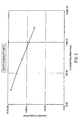
- Figure 1 shows the rheological properties (i . e ., viscosity versus shear rate) of polypropylene.
- Figure 2 shows the rheological properties (i . e ., viscosity versus shear rate) of a thermoplastic elastomer sold under the trademark of C-FLEXTM blended with polypropylene at a weight percent ratio of 80/20.
- Figure 3 shows the rheological properties (i . e ., viscosity versus shear rate) of a thermoplastic elastomer sold under the trademark of C-FLEXTM blended with polypropylene at a weight percent ratio of 85/15.
- Figure 4 shows the rheological properties (i.e. , viscosity versus shear rate) of a thermoplastic elastomer sold under the trademark of C-FLEXTM blended with polypropylene at a weight percent ratio of 90/10.
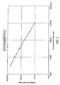
- Figure 5 shows the rheological properties (i . e ., viscosity versus shear rate) of a thermoplastic elastomer sold under the trademark of C-FLEXTM.
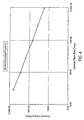
- Figure 6 shows the rheological properties (i . e ., viscosity versus shear rate) of OCRILONTM polyurethane.
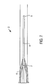
- Figure 7 shows a one-piece catheter device that is formed by practicing the invention.
- Figure 8 shows a top view of a mold used to form an intravascular device in accordance with an embodiment of the invention.
- Figure 9 shows the mold of Figure 8 wherein molten material is injected into the mold though the hub side of the cavity.
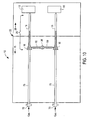
- Figure 10 shows the mold of Figure 8 wherein a fluid such as a gas enters the mold in order to cause the polymer to move through the hub side of the cavity.
- a fluid such as a gas
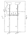
- Figure 11 shows the mold of Figure 8 filled with molten material and with a hollow channel formed by the passage of gas through the cavity.
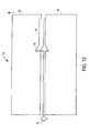
- Figure 12 shows a cross-sectional view of the mold of Figure 8 wherein the first half and second half of the mold are separated.
- Figure 13 shows a top view of a mold wherein a fluid is introduced through the tube of the catheter device in accordance with an embodiment of the invention.
- Figure 14 shows molten material injected into two cavities for forming two catheters in accordance with an embodiment of the invention.
- Figure 15 shows molten material moving through the cavity tube of the catheter with the force of gas passing through the tube in accordance with an embodiment of the invention.
- Figure 16 shows that the molten material has filled the cavities of the mold and with a hollow channel formed by the passage of gas through the cavity in accordance with an embodiment of the invention.
- Figure 17 shows the first half of the mold being separated from the second half of the mold in accordance with an embodiment of the invention.
- Figure 18 shows a first portion of an intravascular device such as a hub that has a base or connector in accordance with an embodiment of the invention.
- Figure 19 shows the same mold as Figure 17 except the molten polymer has been injected into a portion of the hub cavity and the polymer is beginning to solidify in accordance with an embodiment of the invention.
- Figure 20 shows the hub cavity filled with polymer in accordance with an embodiment of the invention.
- Figure 21 shows the first half of the mold separated from the second half of the mold in accordance with an embodiment of the invention.
- Figure 22 shows the hub that was formed in Figures 18-20 is inserted into a second mold in accordance with an embodiment of the invention.
- Figure 23 shows a mold wherein molten polymer has been fed into a portion of the tube cavity in accordance with an embodiment of the invention.
- Figure 24 shows the progression of the molten polymer moving from the proximal portion of the tube to the distal portion of the tube in accordance with an embodiment of the invention.
- Figure 25 shows the polymer continuing to move to the distal portion of the tubs in accordance with an embodiment of the invention.
- Figure 26 continues to show the gas being injected into the gas pin and the polymer has almost filled the tube cavity in accordance with an embodiment of the invention.
- Figure 27 shows that the gas injection has been terminated at the gas pin and the tube cavity is filled with polymer in accordance with an embodiment of the invention.
- Figure 28 shows a cross-section of the hollowed out portion of the tube formed for the intravascular device in accordance with an embodiment of the invention.
- Figure 29 shows the first half of the mold separated from the second half of the mold in accordance with an embodiment of the invention.
- Figure 30 shows an apparatus used to rotate the molds to different locations.
- Figure 31 shows the hub and tube cavity of the one-piece catheter and a portion of an apparatus used in multi-component injection molding in accordance with an embodiment of the invention.
- Figure 32 shows molten polymer fed into a portion of the hub cavity in accordance with an embodiment of the invention.
- Figure 33 shows an insert moving to a position allowing the first cavity and the second cavity to be in communication with one another in accordance with an embodiment of the invention.
- Figure 34 shows a mold wherein the hub has been formed by a polymer and a portion of the tube is formed in accordance with an embodiment of the invention.
- Figure 35 shows polymer filling a portion of the tube cavity in accordance with an embodiment of the invention.
- Figure 36 shows the hub and tube have been formed in accordance with an embodiment of the invention.
- Figure 37 shows a plurality of cavities in a mold used to form a hub and a tube.
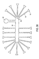
- Figure 38 shows a mold with multiple cavities for forming intravascular devices.
- One embodiment of the invention relates to forming a one-piece catheter using gas assist injection molding manufacturing of material described below.
- the catheter may be formed by using two separate cavities that form a first portion and a second portion. Additionally, a first polymer and a second polymer may be injected into each cavity.
- a one-piece catheter may be formed from a single cavity using one polymer.
- a connector such as a luer lock may be formed. The luer lock allows for the fastening of external delivery tubing to the hub of the intravenous device.
- the gas assist injection molding manufacture of a one-piece catheter typically costs less than that of the traditional method used to manufacture a catheter ( i . e ., (a) injection molding of the hub, (b) extrusion of the catheter tube, and (c) the assembly of both using an eyelet).
- the time used for forming a one-piece catheter is reduced due to the ease of using a single gas assist injection process.
- the one-piece catheter gas assist injection molding process is also less complicated than the conventional processes listed in (a) through (c) provided above. For example, assembly of two or more pieces is not required of the device formed from practicing the invention. Additionally, the bevel at the distal end of the tube does not have to be formed using subsequent thermal or laser operations because the mold incorporates the bevel shape directly into the mold itself.
- Quality and productivity is also increased using the one-piece gas assist manufacturing process.
- the hub may have a defect at the nose section of the hub that may not be noticed until after a hub is fitted to a tube. A large amount of hubs may have been formed before the defect is discovered thereby decreasing productivity.
- tubing produced with dimensional errors results in numerous tubes that must be discarded.
- a one-piece catheter eliminates this problem by forming the entire one-piece catheter simultaneously or at about the same time using a mold that incorporates the precise dimensions required by a particular catheter device.
- rheological properties i . e ., viscosity vs. shear rate
- flexural modulus the hardness of the material
- melt flow the materials should be selected wherein the slope of the viscosity and shear rate is approximately the absolute value of 1.0 poise•seconds or greater.
- Figure 1 shows the rheological properties of polypropylene.
- Figure 1 further provides a slope of -0.433.
- Figure 2 shows the rheological properties of a thermoplastic elastomer sold under the trademark of C-FLEXTM blended with polypropylene.
- FIG. 1 There is a 80/20 by weight ratio of C-FLEXTM to polypropylene.
- Figure 2 further provides a slope of -3.16.
- Figure 3 shows the rheological properties of a thermoplastic elastomer sold under the trademark of C-FLEXTM blended with polypropylene. There is approximately a 85/15 ratio by weight of C-FLEXTM to polypropylene.
- Figure 3 further provides a slope of -0.82.
- Figure 4 shows the rheological properties of a thermoplastic elastomer sold under the trademark of C-FLEXTM wherein the ratio by weight of C-FLEXTM to polypropylene is approximately 90/10.
- Figure 4 further provides a slope of -2.49.
- Figure 5 shows the rheological properties of a thermoplastic elastomer sold under the trademark of C-FLEXTM.
- Figure 5 further provides slopes of approximately -1.54 and -2.26. It is preferable to use C-FLEXTM (90A) or Santoprene® (rheological properties not shown in Figure 5 ). Melt flog that is highly shear sensitive is preferred as shown by a steep slope such as a slope of an absolute value of 1 or greater.
- Figure 6 shows the rheological properties of a polyurethane available under the trademark of OCRILONTM polyurethane (a proprietary polyurethane of Johnson & Johnson Medical). The slope in Figure 6 is -6.7.
- Table 1 provides a summary of some of the slopes taken from the curves presented in Figures 1-6 .
- the flexural modulus of the material is considered in selecting a polymer.
- the flexural modulus of the catheter tubing that is fabricated should be approximately 50,000 psi or higher when the catheter tubing is dry and less than 35,000 psi when the catheter tubing is hydrated.
- a flexural modulus approximately in the range of 25,000 psi and below is preferred for a catheter tubing that is hydrated and 85,000 psi to 150,000 psi is preferred for a catheter tubing that is dry.
- the hardness of the material is also considered in selecting a polymer. Materials exhibiting a hardness approximately in the range of 40 to 75 shore D is preferable.
- Examples of the types of conventional materials that may be used in this molding process for the hub include:
- the preferred hub material to be used is C-FLEXTM and Santoprene® thermoplastic elastomer. With this type of material, the preferred barrel temperature range is 175-300°C and a preferred range of gas pressure used is 1,000-4,000 psi. It will be appreciated that the barrel temperature for some of the materials listed above may reach above 300°C. For example, liquid crystal polymer may be heated to 350°C.
- the preferred materials that may be used for forming the tube include TeflonTM (e . g . fluorinated ethylene propylene copolymer), polyurethanes, rubber-filled polyolefins such as C-FLEXTM and Santoprene® thermoplastic elastomer.
- radiopacity inducing agents such as tungsten, barium sulfate, bismuth compounds and other suitable compounds may be combined with the tube materials. Radiopacity inducing agents permit a healthcare worker to locate a tube in a body in case the tube is broken and moves to a different location in the body.
- an optimum material is selected from any one of the materials listed above for the hub or for the tube except liquid crystal polymers.
- Molding machines that are most appropriate to practice the invention have high speed/low pressure injection capabilities such as the NIIGATA NN35MITM machine commercially available from Daiichi Jitsugyo (America) located in Itasca, Illinois and equipped with a shut-off valve may be used with this and other machines. These machines are generally equipped with two sets of different sized injection cylinders that are symmetrically located and are diagonally opposed to each other and are on either side of the injector device. Injection molding machines use effective size (e.g. volume of the chamber as defined by length and the inner diameter of the cylindrical chamber) of the hydraulic injection cylinder as a pressure control with the flow control valve substantially open.
- effective size e.g. volume of the chamber as defined by length and the inner diameter of the cylindrical chamber
- a single cavity tool should use the high speed/low pressure injection molding machine with a low clamping tonnage such as in the range of 15 and 50 tons.
- a screw diameter of 18 mm is preferred.
- the shot size used should be less than 4.0 ounces.
- a large tonnage (e . g ., up to 150 tons) machine may be required with shot sizes larger than 4 ounces.
- Other conventional machines with shut-off valves are also suitable for this process.
- gas assist machines are used, such as the Bauer programmable NCU (Bauer Compressors located in Norfolk, Virginia).
- Preferred gas assist machines are those that are capable of controlling multiple gas pressure phases.
- the cavity size varies with the gauge of the catheter tube to be fabricated.
- the outer diameter of the catheter tube made by the invention includes large 12 gauge such as 0.112 inches to small 26 gauge such as 0.0216 inches.
- the inner diameter of the catheter tube ranges from 0.1 to 0.021 inches.
- the length of the tube ranges from 2-1/2 to 1/2 inches.
- the hub has an inner diameter that ranges from 0.159 inches to 0.179 inches and an outer diameter that ranges from 0.31 inches to 0.32 inches. Table 2 provides some examples of the specifications of different catheter tubes. However, it will be appreciated that other dimensions may also be used to practice the invention.
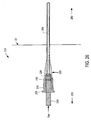
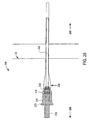
- Figure 7 shows a one-piece catheter device 2 that is formed by practicing the invention.
- the one-piece catheter device has a tube portion 4 and a hub portion 6. It will be appreciated that tube portion 4 of the catheter device 2 is hollow therethrough. This hollow central portion is formed by gas assist injection molding.
- the hub portion is hollow in the central portion of the hub portion 6. At the distal end of hub portion 6 is nose 7. Nose 7 transitions into tube portion 4. Tube portion 4 ends with a tapered bevel 5 at the distal end of tube portion 4.
- Figures 8-12 show one embodiment of the invention wherein injection molding is used and a fluid such as inert gas (e . g ., nitrogen, air, helium, argon, etc.) is introduced through the hub portion of the mold to assist in forming the one-piece catheter hub component. Because the molten polymer enters the hub portion of the cavity, the hub is generally formed first followed by the formation of the tube.
- C-FLEXTM and Santoprene® thermoplastic elastomer used under the operating conditions provided below, is generally capable of overcoming the known limitation of having an aspect ratio > 200 but yet still capable of providing a reliable product.
- Figure 8 shows one-half of the mold used in manufacturing a one-piece catheter hub component.
- a second half [first half (15) and second half (20)] is mated with the illustrated half to form mold 10. Pressure may be applied to the first half 15 against second half 20, to second half 20 against first half 15 or to both halves simultaneously to ensure that cavity 25 is tightly fitted or formed.
- Cavity 25 has a first portion that provides a tube and a second portion that provides a hub.
- Mold 10 has an inlet 30 that allows molten polymer to enter mold 10.
- the molten polymer such as C-FLEXTM and/or Santoprene® thermoplastic elastomer is introduced to mold 10 at a pressure in the approximate range of 4,390 psi to 40,000 psi. Additionally, the molten polymer is generally maintained at a temperature that ranges from 175°C to 220°C. It will be appreciated that other pressures and temperatures are possible depending upon the material used.
- the polymer then moves along runner 50 in the direction of hubs 16.
- FIG. 8 further shows the feed material such as a polymer spreading from runner 50 to hub 16 for both devices.
- Figure 9 shows the same mold as Figure 8 wherein a layer of the polymer forms on the cavity surface and begins to solidify.
- the solidified polymer covers a larger surface of the cavity compared to the solidified polymer shown in mold 10 of Figure 8 .
- the quantity of polymer introduced into cavity 25 is controlled to a small quantity to allow the fluid to advance the polymer further into the cavity surface of mold 10.
- Figure 10 shows a fluid such as gas (e . g . nitrogen gas, air, helium, argon, etc.) entering inlet 70 for mold 10.
- gas e . g . nitrogen gas, air, helium, argon, etc.
- the gas is introduced from a low pressure of 500 psi to as high as 9,000 psi when gas is introduced during the injection molding process.
- pressure builds at the proximal end of hub 16 behind the polymer that was injected. This pressure causes the polymer to move in the distal direction of tube cavity 18.
- gas may be introduced simultaneously or about the same time as the molten polymer is fed into the cavity.
- Figure 11 shows mold 10 having hub 16 and tube 18 filled with polymer but with a hollow channel formed in the tube by the gas.
- the process of filling cavity 25 generally takes 0.5 to 5 seconds. Excess polymer exits an exit channel into a spillover area 13 of the mold. Alternatively, the precise amount of material is used and no polymer is considered excess. This is accomplished by measuring the amount of necessary polymer through applying a short-shot of material into the mold. The amount of polymer used is adjusted until the amount necessary to prevent spillover is determined by adjusting the amount of polymer introduced into cavity 25.
- Figure 12 shows mold 10 wherein first half 15 is separated from second half 20. It will be appreciated that first and second halves (15 and 20) may be mated longitudinally or vertically. The single integral piece may then be removed or ejected by a mechanism in the mold (not shown). The process cycle represented by Figures 8-12 may then be repeated. It will be appreciated that although Figures 8-12 show two devices being manufactured simultaneously, other devices such as a single device or more than two devices, i . e ., multiple devices can be manufactured simultaneously or at approximately the same time.
- a portion of the mold forms the beveled end of a tube.
- a polymer is injected into the hub portion of each of the hub cavities. The polymer then fills the tube portion and the bevel of each of the tube cavities.
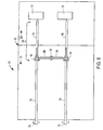
- Figures 13-17 show another embodiment on the invention wherein gas is introduced through the tube of the one-piece catheter and hub of mold 110.
- Figure 13 shows a top view of mold 110 used to form a one-piece catheter and hub.
- Figure 13 further shows a cavity portion for the hub 116 and the tube 118 for two devices. Material such as a polymer is heated until the temperature reaches the melt temperature of the polymer. The molten polymer then enters the tube side of the cavity at inlet 130 of mold 110.
- Figure 13 further shows a gas pin 140 in communication with runner 150.
- Runner 150 communicates with the distal end of tube 118.
- Figure 13 also shows spillover areas beyond hub 116 for the overflow of excess polymer.
- Figure 14 shows the device of Figure 13 with molten material entering inlet 140. While the molten material begins to spread within cavity 125 for both devices. Figure 14 further shows the molten polymer beginning to move in a proximal direction of tubes 118.
- Figure 15 shows that the polymer has continued to advance along tubes 118.
- a fluid such as nitrogen gas, air, helium, argon, etc. enters inlet 170 and moves toward the general direction of runner 150 until the gas contacts the molten material.
- the pressure Upon contacting the molten material, the pressure begins to build behind the molten material and the gas pushes the molten material along the interior of cavity 125.
- the gas pressure is one of the contributing factors that causes the polymer to move through the remainder of the tube and hub cavity creating an interior channel throughout the cavity.
- Figure 16 shows cavity 125 is filled with the polymer material but with a hollow channel formed in the tube by the gas. After a certain time period such as 3-20 seconds, the two halves of the mold are opened and the part is ejected.
- Figure 17 shows first half 115 and second half 120 being separated thereby allowing the one-piece catheter tube and hub devices to be separated from mold 110. The process represented by Figures 13-17 may then be repeated.
- Figures 18-29 show another embodiment of the invention wherein at least two portions of the one-piece catheter component comprise at least two different materials.
- a first portion of the intravascular device is made using one material.
- mold 210 has a cavity for a hub in which the hub portion may be formed first. Mold 210 is then moved or cycled around by a rotating platen in the molding machine (not shown).
- a second material (or, alternatively, the same material) may be injected into a second cavity to form a second portion of the intravascular device such as a tube.
- Figure 18 shows a first portion of an intravascular device such as a hub 216 that has a base or connector 235.
- Connector 235 may be either a male or female luer lock.
- Nose 228 is formed at the end that opposes connector 235. The dimensions of the luer lock should conform to ISO International Standards 594/1 and 594/2. Nose 228 is subsequently coupled to a tube portion of the intravascular device.
- Figure 18 further shows the location 232 of where the polymer may be fed into the hub cavity. It will be appreciated, however, that the inlet to the cavity for the hub for injecting molten polymer may be located anywhere along the hub cavity. For example, molten polymer may be fed in at location 225.
- Figure 19 shows the same first mold 210 as in Figure 18 except the molten polymer has been injected into a portion of hub cavity 216 and the polymer is beginning to solidify.
- Figure 20 shows first mold 210 wherein the molten polymer has filled hub cavity 216 leaving a hollow central portion in the hub. This process generally takes 1-3 seconds. Although gas assist injection molding is not typically used with a hub cavity, this process could be used in forming nose 228.
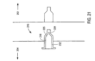
- Figure 21 shows in one embodiment that after the hub has been formed, first half 202 is separated from second half 204.
- the hub that is formed from first mold 210 is then ejected from second half 204 using traditional methods. It will be appreciated, however, that the hub may preferably remain in mold 210 and mold 210 is cycled or rotated around as shown in Figure 30 and described in the accompanying text to second mold 218 wherein the hub is inserted into second mold 218.
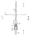
- Figure 22 shows the hub that was formed in the process disclosed in Figures 18-21 is thereafter inserted into a second mold 218.
- Second mold 218 has a tube cavity 255 for forming a tube at the distal end of the hub.
- Figure 22 further shows first half 290 and second half 280 of second mold 218.
- First half 290 and second half 280 are mated together to ensure that the molten polymer stays within the cavity that is present within second mold 218.
- gas pin 250 is inserted thereto. Gas pin 250 is located within the inner diameter of hub.
- a fluid such as a gas (e.g., nitrogen gas, air, helium, argon, etc.) is injected at the proximal end of gas pin 250 and exits outlet 242 of gas pin 250.
- the molten polymer may be fed into a variety of locations for tube cavity 255.
- Inlet 220 shows one location that may be used for injecting molten polymer into tube cavity 255.
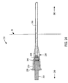
- Figure 23 shows second mold 218 wherein molten polymer has been fed into a portion of tube cavity 255.
- type of polymer that may be used for the tube of the catheter may be different from the polymer that is fed into the hub or they may be the same polymer as explained above. Materials used to form the tube are described above.
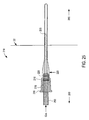
- Figure 24 shows the progression of the molten polymer moving from the proximal portion of the tube to the distal portion of the tube.
- Figures 25-27 shows the polymer continuing to move to the distal portion of the tube cavity.
- Fluid such as gas is introduced at the proximal portion of gas pin 250 as shown in Figures 25 and 26 .
- the pressure of the gas ranges from 500 psi to 9,000 psi and the gas is nitrogen gas, air, helium, argon, etc.
- the introduction of gas pushes the polymer to the distal portion of the tube leaving a polymer skin or tube wall next or adjacent to the mold surface and forming an internal lumen therein.
- pressurized gas presses against the molten polymer causing the molten polymer to advance into regions of the cavity until the cavity is coated with molten polymer as shown in Figure 27 .
- a hollow channel is also formed inside of the tube cavity.
- the pressure of the gas may vary depending upon the material chosen. Other operating conditions may also vary depending upon the materials used to typically form the one-piece catheter. It generally takes up to 60 seconds (typically, it takes less than 15 seconds) from the time molten polymer is introduced until the first cavity is filled.
- Figure 27 shows that the gas introduction has been terminated at gas pin 250 and the tube cavity 255 is filled with polymer with a hollow center therethrough.
- Figure 28 further shows a cross-section of the tube being formed. It will be appreciated that the injection of the gas at gas pin 250 causes the tube to form a hollow central portion 256 of the tube as a result of gas assist injection molding manufacturing.
- Figure 29 shows first half 290 of mold 218 separated from second half 280 of second mold 218.
- the tube is formed and is partially separated from first half 280.
- the process represented by Figures 18-29 may then be repeated.
- Figure 30 illustrates a manufacturing apparatus 400 that may be used to move a first mold that is used to form a hub or a tube to a second mold to form the other portion of the one-piece catheter.
- a rotating mechanism (not shown) is built into the mold itself.
- the manufacturing operation begins by forming a first portion (A) in a first mold.
- the first mold is comprised of two sections (410, 412) that are mated together.
- the first mold is disengaged from position Y1 and moved or rotated to position Y2.
- the second mold comprised of two sections (420, 422) that are mated together is then secured to the first mold using conventional techniques to allow the formation of a second portion using the second mold.
- the first portion may be released using conventional techniques and a robot (not shown) may pick up the first portion (A) and place it into the second mold. Thereafter, the second portion (B) may be formed using the molding process described herein.
- Other apparatus used for moving a first portion (A) after formation include devices that have a turntable for rotating the mold from one position to another. The process represented by Figures 18-30 may then be repeated.
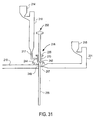
- Figures 31-36 show another embodiment of the invention.
- the hub and the tube mold cavities are initially physically separated from one another by an insert located between the distal end of the hub and the proximal end of the tube.
- Figure 31 shows a portion of an apparatus for multi-component injection molding and the cavities used to form the hub and the tube.
- Containers 214 and 215 are hoppers used to hold solid polymer particles or granules.
- the first polymer is melted and enters first barrel 216 of a double barreled injection molding machine and exits from nozzle 217.
- the molten first polymer enters hub cavity 270 through a sprue(s) and runner(s) and into gate 244.
- Insert 219 at the distal end of hub cavity 270 may move from a first position (X 1 ) to a second position (X 2 ). In its first position, insert 219 blocks off hub cavity 270 from tube cavity 255.
- Gas pin 250 is inserted into the central portion of hub cavity 270 similar to that described above.
- Figure 31 shows that a first polymer is injected into hub cavity 270 through gate 244 and molten polymer moves in two directions such as in the proximal direction of connector 235 and the distal direction of the hub nose.
- Figure 32 shows the molten polymer has filled hub cavity 270. It will be appreciated that the central portion of the hub is hollow and only the outer structure of the hub is filled.
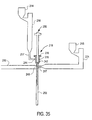
- Figure 33 shows insert 219 has moved to a second position X2 from its prior position of X 1 . This allows hub cavity 270 and tube cavity 255 to be in communication with one another and are no longer physically separated. At this point, the hub is formed and injection of a second polymer will combine at the interface with the first polymer.
- Figure 34 shows that the second polymer has been fed into tube cavity 255 via hopper 215, barrel 221, and nozzle 223. The second polymer begins to move in the distal direction of tube cavity 255 through gate 248.
- a fluid such as a gas (e . g . air, nitrogen gas, helium, argon, etc.) is introduced at inlet 250.
- a gas e . g . air, nitrogen gas, helium, argon, etc.
- Figure 36 shows the tube cavity filled with polymer. However, it will be appreciated that the gas has cored out a longitudinal hollow portion through the tube that is formed. The hollow portion extends from the proximal end to the distal end of the tube.
- hub and tube are then ejected from the mold as a single piece using conventional methods. It will be appreciated that tube cavity 255 could be filled before hub cavity 270 but it is preferred that the hub cavity is filled prior to filling tube cavity 255. Alternatively, hub cavity 270 and tube cavity 255 may be filled with different polymers or the same polymer either simultaneously or at about the same time. The process represented by Figures 31-36 may then be repeated.
- Figure 37 shows another mold wherein a plurality of cavities may be used to form an integral hub and a tube.
- Gas pin 300 is inserted into the hub portion 310 of the device.
- a polymer is injected into the hub portion of the cavity.
- the tube portion 320 of the intravascular device is formed. Either a single polymer may be used to form the hub and the tube or two polymers may be used separately to form the hub and the tube as a single piece.
- Figure 38 shows another mold that may be used to practice the invention.
- Runner 50 communicates with a plurality of tubes 16 and hubs 18.
- the polymer is heated in a molding machine (not shown) until the polymer attains a molten state.
- the polymer is introduced at 24 into the mold and generally moves in the direction of all the cavities simultaneously or about the same speed.
- Gas pin 20 is used to introduce a fluid such as a gas into the cavity of the mold.
- This mold may be used with a single polymer or two polymers.
Abstract
Description
- This invention relates generally to a method of forming an intravascular device and more specifically for fabricating a catheter device.
- Intravascular devices such as catheter assemblies are generally used for passing fluids between a device such as a syringe or a drip to or from body lumens such as veins or arteries, or other internal target sites. Such an assembly usually includes a hub, a catheter tube, and a needle. An eyelet ring is typically inserted into the catheter tube. The catheter tube, together with the eyelet ring, is then inserted into an opening in the nose of the hub and is secured to the hub by press fitting the eyelet ring within the nose of the hub. This hub and tube assembly is then mounted over a sharp needle which is in turn attached to a plastic hub. The sharp tip of the needle is used for piercing a body lumen so that access may be gained into the body lumen by the needle and subsequently the catheter. Once the catheter and the needle are located within the body lumen, the needle is removed and discarded while the catheter tube remains in the body lumen. A syringe or a tube of a drip is then attached to the hub so that fluids may be passed through the hub and the catheter between the drip or the syringe and the body lumen. The hub is typically made of materials that provide sufficient rigidity to securely attach drip lines thereto and the catheter tube is usually made of a material which is flexible and soft to minimize bodily injury.
- Hubs used in catheter assemblies are generally made by using injection molding. However, over-the-needle catheter tubes are usually made by an extrusion process and cut into short pieces instead of a single injection molded piece for two reasons. First, it is generally considered impractical to use a core pin of the same length as the tube in a conventional core pin injection molding process. This is because the core pin is often bent or broken in a high speed manufacturing environment resulting in frequent down time. Second, it is also generally thought by those skilled in the art that the gas assisted injection molding process cannot be used because the length of the tube in relation to the thickness of the thin wall exceeds the generally accepted aspect ratio of greater than 200. The aspect ratio is the length of the cylinder or tube divided by the wall thickness of that cylinder or tube.
- Although plastic needles have been manufactured using injection molding with gas assist manufacturing as shown in United States Patent No. 5,620,639 issued to Stevens et al., a plastic needle is very different than a catheter. First, the geometry of a needle is quite different from that of an intravenous catheter. A needle requires the presence of a sharp point on the distal end of the needle to ease the penetration of the needle into the vascular system, whereas an over-the-needle catheter requires a bevel or taper at the distal end in order to provide a smooth entry of the catheter into the vascular system. The bevel must fit precisely over the needle to allow for the smooth entry of the catheter into the vascular system with the least trauma to the patient. Second, a needle requires the use of a high modulus material for the efficient penetration of the vascular system in contrast to catheters that require flexible and soft materials to minimize bodily injury. Materials with tensile modulii above 10,000 megapascals (MPa), such as liquid crystal polymers and fiber-filled polyamides, are generally suitable for the production of plastic needles whereas materials with tensile modulii of less than 300 MPa are suitable for catheters. Additionally, over-the-needle catheters must have flow rates of the fluids that are to be provided to the patient to conform with ISO International Standard 10555-5, whereas there is no such standard for needles. It is therefore desirable to use a material capable of forming a lengthy, soft and flexible tube for an intravascular device that includes a bevel at the distal end of the tube and a luer lock at the proximal end of a hub.
- An apparatus and a method are disclosed for manufacturing an integral one-piece catheter having a tube and a hub by using a gas assisted injection molding process. The method comprises feeding molten material into a mold having a mold cavity. In one embodiment, the molten material is injected near or into the hub portion of the cavity. In another embodiment, the molten material is injected into the catheter tube portion of the mold. While the polymer is introduced into the cavity, a fluid such as a gas is then injected through an inlet of the mold into the material in the cavity forming a channel throughout the center of the injected material. This may also cause a portion of the molten polymer to be displaced by the gas into a spillover exit.
- Another embodiment of the invention involves forming a first portion of an intravascular device using a first material in a first mold. Thereafter the first portion of the intravascular device is inserted into a second mold to form a second portion using a second material. The second mold is formed on or around the first mold. A fluid such as a gas is then injected through an inlet of the mold into the cavity forming a channel throughout the center of the tube cavity. This may result in a portion of the molten polymer to be displaced by the gas into a spillover exit area.
- In yet another embodiment of the invention, a first portion of the mold is injected with a first material, and a second portion of the cavity is injected with a second material at or around the same time that the first material is injected into the first portion of the cavity. A fluid such as a gas is injected through an inlet of the mold into the cavity. This causes a portion of the molten polymer to be displaced by the gas to conform to the mold with excess material displaced into the spillover exit area. In another embodiment of the invention, injected polymer is precisely measured to prevent spillover of excess molten polymer. In both of the previous cases, a hollow channel is formed throughout the center of the tube cavity.
- Additional features, embodiments, and benefits will be evident in view of the figures and detailed description presented herein.
- The features, aspects, and advantages of the invention will become more thoroughly apparent from the following detailed description, appended claims, and accompanying drawings in which:
- Figure 1 shows the rheological properties (i.e., viscosity versus shear rate) of polypropylene.
- Figure 2 shows the rheological properties (i.e., viscosity versus shear rate) of a thermoplastic elastomer sold under the trademark of C-FLEX™ blended with polypropylene at a weight percent ratio of 80/20.
- Figure 3 shows the rheological properties (i.e., viscosity versus shear rate) of a thermoplastic elastomer sold under the trademark of C-FLEX™ blended with polypropylene at a weight percent ratio of 85/15.
- Figure 4 shows the rheological properties (i.e., viscosity versus shear rate) of a thermoplastic elastomer sold under the trademark of C-FLEX™ blended with polypropylene at a weight percent ratio of 90/10.
- Figure 5 shows the rheological properties (i.e., viscosity versus shear rate) of a thermoplastic elastomer sold under the trademark of C-FLEX™.
- Figure 6 shows the rheological properties (i.e., viscosity versus shear rate) of OCRILON™ polyurethane.
- Figure 7 shows a one-piece catheter device that is formed by practicing the invention.
- Figure 8 shows a top view of a mold used to form an intravascular device in accordance with an embodiment of the invention.
- Figure 9 shows the mold of Figure 8 wherein molten material is injected into the mold though the hub side of the cavity.
- Figure 10 shows the mold of Figure 8 wherein a fluid such as a gas enters the mold in order to cause the polymer to move through the hub side of the cavity.
- Figure 11 shows the mold of Figure 8 filled with molten material and with a hollow channel formed by the passage of gas through the cavity.
- Figure 12 shows a cross-sectional view of the mold of Figure 8 wherein the first half and second half of the mold are separated.
- Figure 13 shows a top view of a mold wherein a fluid is introduced through the tube of the catheter device in accordance with an embodiment of the invention.
- Figure 14 shows molten material injected into two cavities for forming two catheters in accordance with an embodiment of the invention.
- Figure 15 shows molten material moving through the cavity tube of the catheter with the force of gas passing through the tube in accordance with an embodiment of the invention.
- Figure 16 shows that the molten material has filled the cavities of the mold and with a hollow channel formed by the passage of gas through the cavity in accordance with an embodiment of the invention.
- Figure 17 shows the first half of the mold being separated from the second half of the mold in accordance with an embodiment of the invention.
- Figure 18 shows a first portion of an intravascular device such as a hub that has a base or connector in accordance with an embodiment of the invention.
- Figure 19 shows the same mold as Figure 17 except the molten polymer has been injected into a portion of the hub cavity and the polymer is beginning to solidify in accordance with an embodiment of the invention.
- Figure 20 shows the hub cavity filled with polymer in accordance with an embodiment of the invention.
- Figure 21 shows the first half of the mold separated from the second half of the mold in accordance with an embodiment of the invention.
- Figure 22 shows the hub that was formed in Figures 18-20 is inserted into a second mold in accordance with an embodiment of the invention.
- Figure 23 shows a mold wherein molten polymer has been fed into a portion of the tube cavity in accordance with an embodiment of the invention.
- Figure 24 shows the progression of the molten polymer moving from the proximal portion of the tube to the distal portion of the tube in accordance with an embodiment of the invention.
- Figure 25 shows the polymer continuing to move to the distal portion of the tubs in accordance with an embodiment of the invention.
- Figure 26 continues to show the gas being injected into the gas pin and the polymer has almost filled the tube cavity in accordance with an embodiment of the invention.
- Figure 27 shows that the gas injection has been terminated at the gas pin and the tube cavity is filled with polymer in accordance with an embodiment of the invention.
- Figure 28 shows a cross-section of the hollowed out portion of the tube formed for the intravascular device in accordance with an embodiment of the invention.
- Figure 29 shows the first half of the mold separated from the second half of the mold in accordance with an embodiment of the invention.
- Figure 30 shows an apparatus used to rotate the molds to different locations.
- Figure 31 shows the hub and tube cavity of the one-piece catheter and a portion of an apparatus used in multi-component injection molding in accordance with an embodiment of the invention.
- Figure 32 shows molten polymer fed into a portion of the hub cavity in accordance with an embodiment of the invention.
- Figure 33 shows an insert moving to a position allowing the first cavity and the second cavity to be in communication with one another in accordance with an embodiment of the invention.
- Figure 34 shows a mold wherein the hub has been formed by a polymer and a portion of the tube is formed in accordance with an embodiment of the invention.
- Figure 35 shows polymer filling a portion of the tube cavity in accordance with an embodiment of the invention.
- Figure 36 shows the hub and tube have been formed in accordance with an embodiment of the invention.
- Figure 37 shows a plurality of cavities in a mold used to form a hub and a tube.
- Figure 38 shows a mold with multiple cavities for forming intravascular devices.
- In the description that follows, the invention is described with reference to specific embodiments thereof. It will, however, be evident that various modifications and changes may be made thereto without departing from the broader spirit and scope of the invention as set forth in the claims. The specification and drawings are, accordingly, to be regarded in an illustrative rather than a restrictive sense.
- One embodiment of the invention relates to forming a one-piece catheter using gas assist injection molding manufacturing of material described below. The catheter may be formed by using two separate cavities that form a first portion and a second portion. Additionally, a first polymer and a second polymer may be injected into each cavity. In another embodiment, a one-piece catheter may be formed from a single cavity using one polymer. In another embodiment of the invention, a connector such as a luer lock may be formed. The luer lock allows for the fastening of external delivery tubing to the hub of the intravenous device.
- There are significant advantages to using gas assist injection molding manufacturing in order to form a one-piece catheter tube and hub compared to the conventional method of injection molding of the hub, extrusion of the tube, and assembling of both of these elements using an eyelet. The gas assist injection molding manufacture of a one-piece catheter typically costs less than that of the traditional method used to manufacture a catheter (i.e., (a) injection molding of the hub, (b) extrusion of the catheter tube, and (c) the assembly of both using an eyelet). Moreover, the time used for forming a one-piece catheter is reduced due to the ease of using a single gas assist injection process. The one-piece catheter gas assist injection molding process is also less complicated than the conventional processes listed in (a) through (c) provided above. For example, assembly of two or more pieces is not required of the device formed from practicing the invention. Additionally, the bevel at the distal end of the tube does not have to be formed using subsequent thermal or laser operations because the mold incorporates the bevel shape directly into the mold itself.
- Quality and productivity is also increased using the one-piece gas assist manufacturing process. For example, when a hub and a tube are separately formed, the hub may have a defect at the nose section of the hub that may not be noticed until after a hub is fitted to a tube. A large amount of hubs may have been formed before the defect is discovered thereby decreasing productivity. Similarly, in traditional manufacturing, tubing produced with dimensional errors results in numerous tubes that must be discarded. In comparison, a one-piece catheter eliminates this problem by forming the entire one-piece catheter simultaneously or at about the same time using a mold that incorporates the precise dimensions required by a particular catheter device.
- In the discussion provided below, the materials and equipment used to practice the invention are provided followed by the dimensions of the portions (e.g., hub and tube) of the one-piece catheter that may be fabricated practicing the invention. Thereafter, numerous embodiments of the invention are presented.
- A variety of materials may be used to practice the invention. Material selection for the hub and the tube is based upon several factors such as rheological properties (i.e., viscosity vs. shear rate), flexural modulus, the hardness of the material, and melt flow. As shown in Figures 1-6, the materials should be selected wherein the slope of the viscosity and shear rate is approximately the absolute value of 1.0 poise•seconds or greater. For example, Figure 1 shows the rheological properties of polypropylene. Figure 1 further provides a slope of -0.433. Figure 2 shows the rheological properties of a thermoplastic elastomer sold under the trademark of C-FLEX™ blended with polypropylene. There is a 80/20 by weight ratio of C-FLEX™ to polypropylene. Figure 2 further provides a slope of -3.16. Figure 3 shows the rheological properties of a thermoplastic elastomer sold under the trademark of C-FLEX™ blended with polypropylene. There is approximately a 85/15 ratio by weight of C-FLEX™ to polypropylene. Figure 3 further provides a slope of -0.82. Figure 4 shows the rheological properties of a thermoplastic elastomer sold under the trademark of C-FLEX™ wherein the ratio by weight of C-FLEX™ to polypropylene is approximately 90/10. Figure 4 further provides a slope of -2.49. Figure 5 shows the rheological properties of a thermoplastic elastomer sold under the trademark of C-FLEX™. Figure 5 further provides slopes of approximately -1.54 and -2.26. It is preferable to use C-FLEX™ (90A) or Santoprene® (rheological properties not shown in Figure 5). Melt flog that is highly shear sensitive is preferred as shown by a steep slope such as a slope of an absolute value of 1 or greater.
- Figure 6 shows the rheological properties of a polyurethane available under the trademark of OCRILON™ polyurethane (a proprietary polyurethane of Johnson & Johnson Medical). The slope in Figure 6 is -6.7.
- Table 1 provides a summary of some of the slopes taken from the curves presented in Figures 1-6.
Shear Sensitivity of Selected Polymers Summary of Slope Data Type Polymer Temperature ( C) Slope Nylon ULTRAMID B3™ 250 -0.003 Polypropylene polypropylene 210 -0.433 Polypropylene Blends 80/20 C-FLEX™/polypropylene 210 -3.16 85/15 C-FLEX™/polypropylene 210 -0.82 90/10 C-FLEX™/polypropylene 210 -2.49 90/10 C-FLEX™/ polypropylene 175 -7.8 Thermoplastic Elastomer C- FLEX™ 90A (Clear)210 -1.54 C- FLEX™ 90A (White)210 -2.26 ABS/Polyurethane Blend PREVAIL™ 3050 230 -0.073 220 -0.61 210 -1.95 Elastomeric Polyamides Polyetheramide (PEBAX™) 265 -5.56 250 -5 Polyurethane OCRILON™ 210 -6.7 - In addition to rheological properties, the flexural modulus of the material is considered in selecting a polymer. The flexural modulus of the catheter tubing that is fabricated should be approximately 50,000 psi or higher when the catheter tubing is dry and less than 35,000 psi when the catheter tubing is hydrated. A flexural modulus approximately in the range of 25,000 psi and below is preferred for a catheter tubing that is hydrated and 85,000 psi to 150,000 psi is preferred for a catheter tubing that is dry.
- The hardness of the material is also considered in selecting a polymer. Materials exhibiting a hardness approximately in the range of 40 to 75 shore D is preferable.
- Examples of the types of conventional materials that may be used in this molding process for the hub include:
- polyolefins such as polyethylene, polypropylene, TEFLON™ and fluoro-olefinic copolymers such as fluorinated ethylene propylene copolymer (FEP), and blends thereof;
- polyamides, polyetheramides, polyesteramides and blends thereof;
- polyesters;
- polyurethanes such as OCRILON™ resin, a proprietary optically clear radiopaque polyurethane from Johnson & Johnson Medical located in Arlington, Texas; TECOFLEX™ and TECOTHANE™ commercially available from Thermedics, Inc. located in Woburn, Massachusetts and blends of OCRILON™ resin, TECOFLEX™ and TECOTHANE™;
- polycarbonate-based polyurethanes such as CARBOTHANE™ commercially available from Thermedics, Inc., located in Woburn, Massachusetts and blends of OCRILON™, TECOFLEX™, and TECOTHANE™.
- Synthetic thermoplastic elastomers (e.g., polyolefins filled with styrene-ethylene, butylene-styrene block copolymer and polydimethyl siloxane, etc.), an example of which is commercially available as C-FLEX™ from Consolidated Polymer Technologies, Inc. located in Largo, Florida; Santoprene® thermoplastic rubber (highly cross-linked rubber particles dispersed throughout a continuous thermoplastic matrix); commercially available from Advanced Elastomer Systems, Akron, OH; etc.
- Acrylonitrile-butadiene-styrene (ABS) polyurethane blends such as PREVAIL™ commercially available from Dow Chemical, Plastics Division, located in Midland, Michigan;
- Liquid crystal polymers (e.g. 2-napthalene carboxylic acid, 6-(acetyloxy) polymer with 4 (acetyloxy) benzoic acid, aromatic liquid crystal polyester, etc.) commercially available as VECTRA™ from Ticona, a division of Hoechst (Summit, New Jersey) and XYDAR™ from Amoco Polymers, Inc. located in Alpharetta, Georgia;
- Nylons (e.g., commercially available as ULTRAMID B3™ Nylon 6, and fiberglass
reinforced
nylon 6 commercially available from BASF Corporation located in Wyandotte, Michigan. - Polyether nylons such as PEBAX 6333™ and PEBAX 2533™ commercially available
from Elf Atochem North America, Inc. located in Philadelphia, Pennsylvania.
Although this list of compounds provides types of materials that generally may be used with the process described herein, it is to be appreciated that the invention is not limited to these compounds and other like or similar compounds or materials may also be used. - The preferred hub material to be used is C-FLEX™ and Santoprene® thermoplastic elastomer. With this type of material, the preferred barrel temperature range is 175-300°C and a preferred range of gas pressure used is 1,000-4,000 psi. It will be appreciated that the barrel temperature for some of the materials listed above may reach above 300°C. For example, liquid crystal polymer may be heated to 350°C.
- The preferred materials that may be used for forming the tube include Teflon™ (e.g. fluorinated ethylene propylene copolymer), polyurethanes, rubber-filled polyolefins such as C-FLEX™ and Santoprene® thermoplastic elastomer. It will be appreciated that radiopacity inducing agents such as tungsten, barium sulfate, bismuth compounds and other suitable compounds may be combined with the tube materials. Radiopacity inducing agents permit a healthcare worker to locate a tube in a body in case the tube is broken and moves to a different location in the body. In the embodiment in which a one-piece catheter is produced from a single material, an optimum material is selected from any one of the materials listed above for the hub or for the tube except liquid crystal polymers.
- Molding machines that are most appropriate to practice the invention have high speed/low pressure injection capabilities such as the NIIGATA NN35MITM machine commercially available from Daiichi Jitsugyo (America) located in Itasca, Illinois and equipped with a shut-off valve may be used with this and other machines. These machines are generally equipped with two sets of different sized injection cylinders that are symmetrically located and are diagonally opposed to each other and are on either side of the injector device. Injection molding machines use effective size (e.g. volume of the chamber as defined by length and the inner diameter of the cylindrical chamber) of the hydraulic injection cylinder as a pressure control with the flow control valve substantially open. A single cavity tool should use the high speed/low pressure injection molding machine with a low clamping tonnage such as in the range of 15 and 50 tons. A screw diameter of 18 mm is preferred. The shot size used should be less than 4.0 ounces. For multi-cavity tooling, a large tonnage (e.g., up to 150 tons) machine may be required with shot sizes larger than 4 ounces. Other conventional machines with shut-off valves are also suitable for this process.
- In conjunction with injection molding machine, gas assist machines are used, such as the Bauer programmable NCU (Bauer Compressors located in Norfolk, Virginia). Preferred gas assist machines are those that are capable of controlling multiple gas pressure phases.
- The cavity size varies with the gauge of the catheter tube to be fabricated. For example, the outer diameter of the catheter tube made by the invention includes large 12 gauge such as 0.112 inches to small 26 gauge such as 0.0216 inches. The inner diameter of the catheter tube ranges from 0.1 to 0.021 inches. The length of the tube ranges from 2-1/2 to 1/2 inches. The hub has an inner diameter that ranges from 0.159 inches to 0.179 inches and an outer diameter that ranges from 0.31 inches to 0.32 inches. Table 2 provides some examples of the specifications of different catheter tubes. However, it will be appreciated that other dimensions may also be used to practice the invention.
Examples of Dimensions of Fabricated Tubes ((millimeters) (mm)) Outer Diameter Of Tube Inner Diameter Of Tube Length Of Tube Wall Thickness Of Tube Gauge 2.13 1.75 31 0.19 14 2.13 1.75 56 0.19 14 1.70 1.38 31 0.16 16 1.70 1.38 56 0.16 16 1.28 0.98 44 0.15 18 1.28 0.98 31 0.15 18 1.10 0.80 31 0.15 20 1.10 0.80 25 0.15 20 1.10 0.80 44 0.15 20 0.83 0.63 25 0.10 22 0.70 0.50 19 0.10 24 - Figure 7 shows a one-piece catheter device 2 that is formed by practicing the invention. The one-piece catheter device has a
tube portion 4 and ahub portion 6. It will be appreciated thattube portion 4 of the catheter device 2 is hollow therethrough.
This hollow central portion is formed by gas assist injection molding. The hub portion is hollow in the central portion of thehub portion 6. At the distal end ofhub portion 6 is nose 7. Nose 7 transitions intotube portion 4.Tube portion 4 ends with atapered bevel 5 at the distal end oftube portion 4. - Figures 8-12 show one embodiment of the invention wherein injection molding is used and a fluid such as inert gas (e.g., nitrogen, air, helium, argon, etc.) is introduced through the hub portion of the mold to assist in forming the one-piece catheter hub component. Because the molten polymer enters the hub portion of the cavity, the hub is generally formed first followed by the formation of the tube. C-FLEX™ and Santoprene® thermoplastic elastomer, used under the operating conditions provided below, is generally capable of overcoming the known limitation of having an aspect ratio > 200 but yet still capable of providing a reliable product. Figure 8 shows one-half of the mold used in manufacturing a one-piece catheter hub component. A second half (not shown) [first half (15) and second half (20)] is mated with the illustrated half to form
mold 10. Pressure may be applied to thefirst half 15 againstsecond half 20, tosecond half 20 againstfirst half 15 or to both halves simultaneously to ensure thatcavity 25 is tightly fitted or formed.Cavity 25 has a first portion that provides a tube and a second portion that provides a hub. -
Mold 10 has aninlet 30 that allows molten polymer to entermold 10. The molten polymer such as C-FLEX™ and/or Santoprene® thermoplastic elastomer is introduced to mold 10 at a pressure in the approximate range of 4,390 psi to 40,000 psi. Additionally, the molten polymer is generally maintained at a temperature that ranges from 175°C to 220°C. It will be appreciated that other pressures and temperatures are possible depending upon the material used. The polymer then moves alongrunner 50 in the direction ofhubs 16. - The two halves (15 and 20) meet at
split line 22. Atsplit line 22, inlet for fluid flow is not open for fluids such as nitrogen gas, air, helium, argon, etc. to entermold 10. Figure 8 further shows the feed material such as a polymer spreading fromrunner 50 tohub 16 for both devices. - Figure 9 shows the same mold as Figure 8 wherein a layer of the polymer forms on the cavity surface and begins to solidify. The solidified polymer covers a larger surface of the cavity compared to the solidified polymer shown in
mold 10 of Figure 8. The quantity of polymer introduced intocavity 25 is controlled to a small quantity to allow the fluid to advance the polymer further into the cavity surface ofmold 10. - Figure 10 shows a fluid such as gas (e.g. nitrogen gas, air, helium, argon, etc.) entering
inlet 70 formold 10. The gas is introduced from a low pressure of 500 psi to as high as 9,000 psi when gas is introduced during the injection molding process. As the gas passes throughtube 75, pressure builds at the proximal end ofhub 16 behind the polymer that was injected. This pressure causes the polymer to move in the distal direction oftube cavity 18. It will be appreciated that although gas is shown to be introduced after the polymer is fed into the cavity, the gas may be introduced simultaneously or about the same time as the molten polymer is fed into the cavity. - Figure 11 shows
mold 10 havinghub 16 andtube 18 filled with polymer but with a hollow channel formed in the tube by the gas. The process of fillingcavity 25 generally takes 0.5 to 5 seconds. Excess polymer exits an exit channel into aspillover area 13 of the mold. Alternatively, the precise amount of material is used and no polymer is considered excess. This is accomplished by measuring the amount of necessary polymer through applying a short-shot of material into the mold. The amount of polymer used is adjusted until the amount necessary to prevent spillover is determined by adjusting the amount of polymer introduced intocavity 25. - After -the polymer has begun to solidify, Figure 12 shows
mold 10 whereinfirst half 15 is separated fromsecond half 20. It will be appreciated that first and second halves (15 and 20) may be mated longitudinally or vertically. The single integral piece may then be removed or ejected by a mechanism in the mold (not shown). The process cycle represented by Figures 8-12 may then be repeated. It will be appreciated that although Figures 8-12 show two devices being manufactured simultaneously, other devices such as a single device or more than two devices, i.e., multiple devices can be manufactured simultaneously or at approximately the same time. - Preferably, a portion of the mold forms the beveled end of a tube. In this embodiment of the invention, a polymer is injected into the hub portion of each of the hub cavities. The polymer then fills the tube portion and the bevel of each of the tube cavities.
- Figures 13-17 show another embodiment on the invention wherein gas is introduced through the tube of the one-piece catheter and hub of
mold 110. Figure 13 shows a top view ofmold 110 used to form a one-piece catheter and hub. Figure 13 further shows a cavity portion for thehub 116 and thetube 118 for two devices. Material such as a polymer is heated until the temperature reaches the melt temperature of the polymer. The molten polymer then enters the tube side of the cavity atinlet 130 ofmold 110. Figure 13 further shows agas pin 140 in communication withrunner 150.Runner 150 communicates with the distal end oftube 118. Figure 13 also shows spillover areas beyondhub 116 for the overflow of excess polymer. - Figure 14 shows the device of Figure 13 with molten
material entering inlet 140. While the molten material begins to spread withincavity 125 for both devices. Figure 14 further shows the molten polymer beginning to move in a proximal direction oftubes 118. - Figure 15 shows that the polymer has continued to advance along
tubes 118. Before the polymer fillscavity 125, the amount of polymer entering thecavity 125 is consumed. At this point, a fluid such as nitrogen gas, air, helium, argon, etc. entersinlet 170 and moves toward the general direction ofrunner 150 until the gas contacts the molten material. Upon contacting the molten material, the pressure begins to build behind the molten material and the gas pushes the molten material along the interior ofcavity 125. The gas pressure is one of the contributing factors that causes the polymer to move through the remainder of the tube and hub cavity creating an interior channel throughout the cavity. - Figure 16 shows
cavity 125 is filled with the polymer material but with a hollow channel formed in the tube by the gas. After a certain time period such as 3-20 seconds, the two halves of the mold are opened and the part is ejected. Figure 17 showsfirst half 115 andsecond half 120 being separated thereby allowing the one-piece catheter tube and hub devices to be separated frommold 110. The process represented by Figures 13-17 may then be repeated. - Figures 18-29 show another embodiment of the invention wherein at least two portions of the one-piece catheter component comprise at least two different materials. A first portion of the intravascular device is made using one material. For example,
mold 210 has a cavity for a hub in which the hub portion may be formed first.Mold 210 is then moved or cycled around by a rotating platen in the molding machine (not shown). A second material (or, alternatively, the same material) may be injected into a second cavity to form a second portion of the intravascular device such as a tube. - Figure 18 shows a first portion of an intravascular device such as a
hub 216 that has a base orconnector 235.Connector 235 may be either a male or female luer lock.Nose 228 is formed at the end that opposesconnector 235. The dimensions of the luer lock should conform to ISO International Standards 594/1 and 594/2.Nose 228 is subsequently coupled to a tube portion of the intravascular device. Figure 18 further shows thelocation 232 of where the polymer may be fed into the hub cavity. It will be appreciated, however, that the inlet to the cavity for the hub for injecting molten polymer may be located anywhere along the hub cavity. For example, molten polymer may be fed in atlocation 225. Figure 19 shows the samefirst mold 210 as in Figure 18 except the molten polymer has been injected into a portion ofhub cavity 216 and the polymer is beginning to solidify. - Figure 20 shows
first mold 210 wherein the molten polymer has filledhub cavity 216 leaving a hollow central portion in the hub. This process generally takes 1-3 seconds. Although gas assist injection molding is not typically used with a hub cavity, this process could be used in formingnose 228. - Figure 21 shows in one embodiment that after the hub has been formed,
first half 202 is separated fromsecond half 204. The hub that is formed fromfirst mold 210 is then ejected fromsecond half 204 using traditional methods. It will be appreciated, however, that the hub may preferably remain inmold 210 andmold 210 is cycled or rotated around as shown in Figure 30 and described in the accompanying text tosecond mold 218 wherein the hub is inserted intosecond mold 218. Figure 22 shows the hub that was formed in the process disclosed in Figures 18-21 is thereafter inserted into asecond mold 218.Second mold 218 has atube cavity 255 for forming a tube at the distal end of the hub. Figure 22 further showsfirst half 290 andsecond half 280 ofsecond mold 218.First half 290 andsecond half 280 are mated together to ensure that the molten polymer stays within the cavity that is present withinsecond mold 218. At the proximal portion of the hub,gas pin 250 is inserted thereto.Gas pin 250 is located within the inner diameter of hub. A fluid such as a gas (e.g., nitrogen gas, air, helium, argon, etc.) is injected at the proximal end ofgas pin 250 and exitsoutlet 242 ofgas pin 250. The molten polymer may be fed into a variety of locations fortube cavity 255.Inlet 220 shows one location that may be used for injecting molten polymer intotube cavity 255. - Figure 23 shows
second mold 218 wherein molten polymer has been fed into a portion oftube cavity 255. It should be noted that the type of polymer that may be used for the tube of the catheter may be different from the polymer that is fed into the hub or they may be the same polymer as explained above. Materials used to form the tube are described above. Figure 24 shows the progression of the molten polymer moving from the proximal portion of the tube to the distal portion of the tube. - Figures 25-27 shows the polymer continuing to move to the distal portion of the tube cavity. Fluid such as gas is introduced at the proximal portion of
gas pin 250 as shown in Figures 25 and 26. The pressure of the gas ranges from 500 psi to 9,000 psi and the gas is nitrogen gas, air, helium, argon, etc. The introduction of gas pushes the polymer to the distal portion of the tube leaving a polymer skin or tube wall next or adjacent to the mold surface and forming an internal lumen therein. As noted above, pressurized gas presses against the molten polymer causing the molten polymer to advance into regions of the cavity until the cavity is coated with molten polymer as shown in Figure 27. A hollow channel is also formed inside of the tube cavity. It will be appreciated however, that the pressure of the gas may vary depending upon the material chosen. Other operating conditions may also vary depending upon the materials used to typically form the one-piece catheter. It generally takes up to 60 seconds (typically, it takes less than 15 seconds) from the time molten polymer is introduced until the first cavity is filled. Figure 27 shows that the gas introduction has been terminated atgas pin 250 and thetube cavity 255 is filled with polymer with a hollow center therethrough. - Figure 28 further shows a cross-section of the tube being formed. It will be appreciated that the injection of the gas at
gas pin 250 causes the tube to form a hollowcentral portion 256 of the tube as a result of gas assist injection molding manufacturing. - Figure 29 shows
first half 290 ofmold 218 separated fromsecond half 280 ofsecond mold 218. The tube is formed and is partially separated fromfirst half 280. The process represented by Figures 18-29 may then be repeated. - Figure 30 illustrates a
manufacturing apparatus 400 that may be used to move a first mold that is used to form a hub or a tube to a second mold to form the other portion of the one-piece catheter. In one embodiment, a rotating mechanism (not shown) is built into the mold itself. - There are two molds for forming a first and a second portion (A, B) of the one-piece catheter. The manufacturing operation begins by forming a first portion (A) in a first mold. The first mold is comprised of two sections (410, 412) that are mated together. After the first portion such as a hub has been formed, the first mold is disengaged from position Y1 and moved or rotated to position Y2. The second mold comprised of two sections (420, 422) that are mated together is then secured to the first mold using conventional techniques to allow the formation of a second portion using the second mold. It will be appreciated that instead of the second mold being secured to a first mold after the first portion is formed, the first portion may be released using conventional techniques and a robot (not shown) may pick up the first portion (A) and place it into the second mold. Thereafter, the second portion (B) may be formed using the molding process described herein. Other apparatus used for moving a first portion (A) after formation include devices that have a turntable for rotating the mold from one position to another. The process represented by Figures 18-30 may then be repeated.
- Figures 31-36 show another embodiment of the invention. In this embodiment, the hub and the tube mold cavities are initially physically separated from one another by an insert located between the distal end of the hub and the proximal end of the tube.
- Figure 31 shows a portion of an apparatus for multi-component injection molding and the cavities used to form the hub and the tube.
Containers first barrel 216 of a double barreled injection molding machine and exits fromnozzle 217. The molten first polymer entershub cavity 270 through a sprue(s) and runner(s) and intogate 244.Insert 219 at the distal end ofhub cavity 270 may move from a first position (X1) to a second position (X2). In its first position, insert 219 blocks offhub cavity 270 fromtube cavity 255.Gas pin 250 is inserted into the central portion ofhub cavity 270 similar to that described above. Figure 31 shows that a first polymer is injected intohub cavity 270 throughgate 244 and molten polymer moves in two directions such as in the proximal direction ofconnector 235 and the distal direction of the hub nose. Figure 32 shows the molten polymer has filledhub cavity 270. It will be appreciated that the central portion of the hub is hollow and only the outer structure of the hub is filled. - Figure 33 shows insert 219 has moved to a second position X2 from its prior position of X1. This allows
hub cavity 270 andtube cavity 255 to be in communication with one another and are no longer physically separated. At this point, the hub is formed and injection of a second polymer will combine at the interface with the first polymer. Figure 34 shows that the second polymer has been fed intotube cavity 255 viahopper 215,barrel 221, and nozzle 223. The second polymer begins to move in the distal direction oftube cavity 255 throughgate 248. In Figure 35, a fluid such as a gas (e.g. air, nitrogen gas, helium, argon, etc.) is introduced atinlet 250. Gas exits gas pin at 242 wherein the gas pin is inserted throughhub cavity 270 and ends at the distal end of the nose portion 240 ofhub cavity 270. Gas pushes the central portion of the molten polymer to the distal portion oftube cavity 255 forming a tube. - Figure 36 shows the tube cavity filled with polymer. However, it will be appreciated that the gas has cored out a longitudinal hollow portion through the tube that is formed. The hollow portion extends from the proximal end to the distal end of the tube.
- The hub and tube are then ejected from the mold as a single piece using conventional methods. It will be appreciated that
tube cavity 255 could be filled beforehub cavity 270 but it is preferred that the hub cavity is filled prior to fillingtube cavity 255. Alternatively,hub cavity 270 andtube cavity 255 may be filled with different polymers or the same polymer either simultaneously or at about the same time. The process represented by Figures 31-36 may then be repeated. - Figure 37 shows another mold wherein a plurality of cavities may be used to form an integral hub and a tube.
Gas pin 300 is inserted into thehub portion 310 of the device. In this embodiment of the invention, a polymer is injected into the hub portion of the cavity. During or after the hub has been formed, thetube portion 320 of the intravascular device is formed. Either a single polymer may be used to form the hub and the tube or two polymers may be used separately to form the hub and the tube as a single piece. - Figure 38 shows another mold that may be used to practice the invention.
Runner 50 communicates with a plurality oftubes 16 andhubs 18. The polymer is heated in a molding machine (not shown) until the polymer attains a molten state. The polymer is introduced at 24 into the mold and generally moves in the direction of all the cavities simultaneously or about the same speed.Gas pin 20 is used to introduce a fluid such as a gas into the cavity of the mold. This mold may be used with a single polymer or two polymers. - In the preceding detailed description, the invention is described with reference to specific embodiments thereof. It will, however, be evident that various modifications and changes may be made thereto without departing from the broader spirit and scope of the invention as set forth in the claims. The specification and drawings are, accordingly, to be regarded in an illustrative rather than a restrictive sense.
Claims (58)
- A method for manufacturing a one-piece catheter and hub, comprising:feeding a molten polymer into a mold having a mold cavity with a tube portion and a hub portion extending from the tube portion;forming a hub;injecting a fluid under pressure into a gate of the cavity;feeding a polymer in the tube portion of the cavity; andforming a tube having an orifice therethrough.
- The method of claim 1, wherein the fluid is nitrogen gas, air, helium or argon.
- The method of claim 1 or claim 2 wherein the mold cavity has a first portion and a second portion, the first portion is a hub cavity and a second portion is a tube cavity.
- The method of any one of claims 1 to 3, wherein the fluid is injected into a portion of the cavity, wherein the portion of the cavity is the hub portion or the tube portion.
- The method of any one of claims 1 to 4, further comprising feeding a molten polymer into the mold cavity along a runner under pressure from a molding machine, a solidified layer of the polymer forming on the mold surface; introducing a fluid into the cavity to push molten polymer along the orifice created within the region of the cavity to form the orifice and to continue the passage of polymer along the remaining length of the cavity completing the formation of the solidified layer of polymer on the mold surface.
- The method of any one of claims 1 to 5, wherein the hub portion has formed thereon at least one of a male lock and a female lock.
- The method of any one of claims 1 to 6, wherein the flow rate of the polymer is sufficient so as to fill the cavity in 0.5 to 5 seconds.
- The method of any one of claims 1 to 7, wherein the feeding of polymer continues until the cavity is filled; and fluid is injected into the mold.
- The method of any one of claims 1 to 8, wherein the outer diameter of the tube increases along its length toward the hub and the increase in the diameter is substantially constant to provide a substantially straight taper.
- The method of any one of claims 1 to 9, further comprising purging the fluid through an exit channel.
- The method of any one of claims 1 to 10, wherein a radiopaque inducing agent, which preferably is selected from the group consisting of tungsten, barium sulfate, and bismuth compounds, is combined with the polymer.
- A method of making a hub and a catheter tube comprising:feeding a molten polymer into a mold having a mold cavity with a hub cavity and a tube cavity, wherein the hub cavity extends from the tube cavity wherein a molten polymer is injected into the mold through an inlet to one of the hub cavity and the tube cavity; introducing gas through the hub; andforming a tube.
- A method of making a hub and a tube, comprising:injecting a first polymer into a first cavity of a first mold;molding a first portion in a cavity for the first portion of a first mold;removing the first portion from the first cavity of a first mold;inserting the first portion into a second mold;injecting a second polymer into a second cavity of a second mold;molding a second portion in a cavity for the second portion; andinjecting a fluid through an inlet of the second mold wherein the fluid pushes a second polymer forming a tube from a first length to a second length.
- The method of claim 13, wherein a nose is formed between the hub and the tube.
- The method of claim 13 or claim 14, wherein the first portion is a hub.
- The method of claim 15, wherein the second portion is a tube.
- A method of making an intravascular device through injection molding comprising:injecting a first polymer into a first cavity in the first mold;molding a first portion;removing the first portion from the first mold;placing the first portion into a second mold;injecting a second polymer into a second mold wherein the second polymer begins to solidify in a second cavity of the second mold; andintroducing a fluid through a fluid inlet, the fluid causing the second polymer to move along the surface of the second cavity.
- The method of any one of claims 1 to 17, wherein the temperature of the molten material is approximately in the range of 175°C to 300°C, preferably 175°C to 220°C.
- The method of: any one of claims 1 to 11 wherein the pressure within a cavity of the mold; or the method of any one of claims 12 to 18 wherein the pressure in a first phase of injection molding, is approximately in the range of 1,000 psi to 40,000 psi.
- The method of claim 12 or claim 17 or any claim dependent thereon, wherein pressure in a second phase of the injection molding process is approximately in the range of 1,000 psi to approximately 40,000 psi.
- The method of claim 20, wherein the first phase of injection molding relates to the pressure inside a chamber used to allow the polymer to become molten.
- The method of claim 12 or claim 17 or any claim dependent thereon, wherein the second cavity is beveled at a distal end of the tube.
- A method of making an intravascular device using injection molding and gas assist manufacturing, comprising:injecting a first polymer into a first cavity of a mold;injecting a second polymer into a second cavity of the mold; andintroducing a fluid through an inlet of the mold which forms a tube.
- The method of claim 23 wherein the mold is advanced from a first position to a second position of the molding machine, the second position allowing the second polymer to be injected into the mold.
- The method of claim 23 or claim 24, wherein the aspect ratio is about 200.
- A method of manufacturing an intravascular device using injection molding and gas assist manufacturing, comprising:injecting a polymer into a cavity of a mold, the mold having a single cavity, the cavity having a hub portion and a tube portion;introducing a fluid through an inlet of the mold wherein the mold forms a portion of the intravascular device; andthe intravascular device formed by injecting molding has an aspect ratio of about 200.
- The method of any one of claims 1 to 26, wherein the tube portion is beveled at its distal end.
- A method of making a one-piece hub and tube, the method comprising:injecting a first polymer into a first cavity;injecting a second polymer into a second cavity; andintroducing a fluid into a second cavity having a second polymer.
- The method of claim 28, further comprising moving an insert from a first position to a second position.
- The method of: any one of claims 1 to 12, 28 to 29 wherein the polymer; or any one of claims 13 to 22 wherein the first portion comprises a polymer; or any one of claims 23 to 25, wherein the or the first polymer is selected from the group consisting a polyolefins filled with elastomeric polymers, polyesteramide, polyurethane, polyetheramide, polycarbonate, polyester, polyamide, acrylonitrile-butadiene-styrene, fluorinated ethylene propylene copolymer and liquid crystal polymers.
- The method of any one of claims 13 to 17, 23, 24 and 28 to 30, wherein the second polymer is selected from the group consisting of polyurethane, polyfluoropolyolefins, elastomeric components blended in polypropylene.
- The method of any one of claims 1 to 10 and 26 to 31, wherein the first polymer was selected based upon the slope of viscosity versus shear rate, wherein the negative slope is greater than an absolute value of 1.0.
- The method of claim 28, further comprising measuring the polymer injected into the cavity thereby eliminating spillover of the polymer.
- The method of claim 28, wherein the second cavity is beveled at a distal end.
- A method of making a hub and a tube, comprising:injecting a first polymer into a first cavity of a first mold;molding a first portion in a cavity for the first portion of a first mold;removing the first portion from the first cavity of a first mold;inserting the first portion into a second mold;injecting a second polymer into a second cavity of a second mold;molding a second portion in a cavity for the second portion; andinjecting a fluid through an inlet of the second mold wherein the fluid pushes a second polymer forming a tube from a first point to a second point having an orifice therethrough and leaving a third point to a fourth point wherein the third point to a fourth point of the tube is solid.
- The method of claim 35, further comprising cutting the third point to a fourth point of the tube.
- A method of making a hub and a tube, comprising:injecting a polymer into a first cavity of a first mold;molding a first portion in a cavity for the first portion of a first mold;removing the first portion from the first cavity of a first mold;inserting the first portion into a second mold;injecting the polymer into a second cavity of a second mold;molding a second portion in a cavity for the second portion; andinjecting a fluid through an inlet of the second mold wherein the fluid pushes a second polymer forming a tube from a first length to a second length having an orifice therethrough and leaving a third length to a fourth length wherein the third length to a fourth length of the tube is substantially solid.
- An apparatus for forming a single-piece catheter, comprising:a mold cavity with a tube portion and a hub portion extending from the tube portion, the mold cavity having an orifice to receive a molten polymer; anda fluid which is injected under pressure into a gate of the cavity.
- The apparatus of claim 38, wherein the hub portion has a cavity for forming a lock at the proximal end of the hub portion.
- The apparatus of claim 38 or claim 39, wherein the polymer is combined with a radiopaque inducing agent which preferably is selected from the group consisting of tungsten, barium sulfate, and bismuth compounds.
- An apparatus used for making a single-piece catheter, comprising:means for injecting a first polymer into a first cavity of a first mold to form a first portion; means for inserting the first portion into a second mold;mean for injecting a second polymer into a second cavity of a second mold to form a second portion;means for injecting a fluid through an inlet of the second mold wherein the fluid pushes a second polymer forming a tube from a first length to a second length.
- The apparatus of claim 36 or claim 41, wherein the tube or second portion has a beveled distal end.
- The apparatus of claim 41, wherein the first portion has a cavity for forming a lock 5 at the proximal end of the first portion.
- The apparatus of claim 38 or claim 41, wherein the lock is substantially cylindrical in shape.
- The apparatus of claim 38 or claim 41, wherein the orifice is located in the hub portion or in the first portion of the cavity.
- The apparatus of claim 38 or claim 41, wherein the orifice is located in the tube portion of the cavity.
- The apparatus of claim 41, wherein the first length of the second portion is hollow.
- The apparatus of claim 41, wherein the second length of the second portion is hollow.
- The apparatus of claim 41 wherein the first length of the second portion is solid.
- The apparatus of claim 41, wherein the first portion is rotated from a first position to a second position; and the first portion is secured to a second mold.
- A mold for forming a single-piece hub and tube comprising:a mold cavity with a tube portion and a hub portion extending from the tube portion, the mold cavity having an aperture to receive a molten polymer;the hub portion has a connector portion at the proximal end of the hub portion;the tube portion has a distal end which is beveled;a first polymer is injected into the hub portion;a second polymer is injected into the tube portion; anda fluid which is injected under pressure into a gate of the cavity.
- The apparatus of any one of claims 39, 41 and 51 wherein the lock or the connector portion is one of a male lock and a female lock.
- The apparatus of claim 38, 41 or 51 wherein the aspect ratio is greater than 200.
- The apparatus of claim 51 wherein the connector portion is substantially cylindrical in shape.
- The apparatus of claim 51, wherein the orifice is located in at least one of the hub portion and tube portion of the cavity.
- The apparatus of claim 51, wherein a hub portion which is formed is from the hub portion of the mold cavity is rotated by a rotator coupled in the mold from a first position to a second position; and the hub portion is secured to a second mold.
- The apparatus of any one of claims 38 to 56, wherein the first polymer is selected from the group consisting of polyolefins filled with elastomeric polymers, polyesteramide, polyurethane, polyetheramide, polycarbonate, polyester, polyamide, acrylonitrile-butadiene-styrene, fluorinated ethylene propylene copolymer and liquid crystal polymers, or any combination thereof.
- The apparatus of claim 41 or claim 51, wherein the second polymer is selected from the group consisting of polyurethane, polyfluoropolyolefins, elastomeric components blended in polypropylene.
Applications Claiming Priority (2)
| Application Number | Priority Date | Filing Date | Title |
|---|---|---|---|
| US09/476,411 US6630086B1 (en) | 1999-12-30 | 1999-12-30 | Gas assist molding of one-piece catheters |
| US476411 | 1999-12-30 |
Publications (3)
| Publication Number | Publication Date |
|---|---|
| EP1116567A2 true EP1116567A2 (en) | 2001-07-18 |
| EP1116567A3 EP1116567A3 (en) | 2003-01-02 |
| EP1116567B1 EP1116567B1 (en) | 2006-03-01 |
Family
ID=23891720
Family Applications (1)
| Application Number | Title | Priority Date | Filing Date |
|---|---|---|---|
| EP00311765A Expired - Lifetime EP1116567B1 (en) | 1999-12-30 | 2000-12-29 | Gas assist molding of one-piece catheters |
Country Status (15)
| Country | Link |
|---|---|
| US (2) | US6630086B1 (en) |
| EP (1) | EP1116567B1 (en) |
| JP (1) | JP4675476B2 (en) |
| AT (1) | ATE318687T1 (en) |
| AU (1) | AU774205B2 (en) |
| BR (1) | BR0100153A (en) |
| CA (1) | CA2329970C (en) |
| CO (1) | CO5300431A1 (en) |
| DE (1) | DE60026259T2 (en) |
| DK (1) | DK1116567T3 (en) |
| ES (1) | ES2259595T3 (en) |
| MX (1) | MXPA01000109A (en) |
| PT (1) | PT1116567E (en) |
| SG (1) | SG98437A1 (en) |
| ZA (1) | ZA200100036B (en) |
Cited By (10)
| Publication number | Priority date | Publication date | Assignee | Title |
|---|---|---|---|---|
| WO2003099544A1 (en) * | 2002-05-27 | 2003-12-04 | Tec Tubes Sweden Ab | Tube, method and tool for its manufacture |
| EP1504870A2 (en) * | 2003-08-08 | 2005-02-09 | Becton Dickinson and Company | Catheter assemblies and injection molding processes and equipment for making the same |
| US6887417B1 (en) | 2001-11-05 | 2005-05-03 | Bectondickinson And Company | Catheter sleeve assembly and one step injection molding process for making the same |
| US7431876B2 (en) | 2003-11-14 | 2008-10-07 | Unomedical A/S | Injection moulding of a catheter |
| US7887737B2 (en) | 2003-11-14 | 2011-02-15 | Unomedical, A/S | Injection moulding of a catheter |
| US8123892B2 (en) * | 2003-09-26 | 2012-02-28 | Tyco Healthcare Group Lp | Urology catheter |
| WO2017102843A1 (en) * | 2015-12-18 | 2017-06-22 | Kautex Textron Gmbh & Co. Kg | Injection-moulding device for producing multi-component mouldings and method for producing multi-component mouldings |
| EP1941927B1 (en) * | 2001-06-29 | 2017-08-30 | Coloplast A/S | A method of producing a catheter and a catheter |
| US10441454B2 (en) | 2001-06-29 | 2019-10-15 | Coloplast A/S | Urinary catheter provided as a package |
| US10478592B2 (en) | 2011-08-31 | 2019-11-19 | Becton, Dickinson And Company | Systems and methods to increase rigidity and snag-resistance of catheter tip |
Families Citing this family (30)
| Publication number | Priority date | Publication date | Assignee | Title |
|---|---|---|---|---|
| US7311698B2 (en) | 2001-09-24 | 2007-12-25 | Coloplast A/S | Urinary catheter assembly allowing for non-contaminated insertion of the catheter into a urinary canal |
| US7517343B2 (en) | 2001-06-29 | 2009-04-14 | Coloplast A/S | Catheter assembly |
| US7910047B2 (en) * | 2002-09-26 | 2011-03-22 | Lancer Partnership, Ltd. | Through fittings and a method for gas assist molding of through fittings |
| US7407498B2 (en) * | 2003-09-02 | 2008-08-05 | Boston Scientific Scimed, Inc. | Construction of medical components using gas assisted microcellular foaming |
| US7455806B2 (en) * | 2003-12-10 | 2008-11-25 | William A. Cook Australia Pty. Ltd. | Injection moulding of functional cavities |
| KR101243401B1 (en) * | 2004-10-29 | 2013-03-13 | 코니카 미놀타 어드밴스드 레이어즈 인코포레이티드 | Optical component production system and method for producing the same |
| US7214420B2 (en) * | 2005-05-23 | 2007-05-08 | Robert Joyce | Molded article |
| US20100130937A1 (en) * | 2005-06-30 | 2010-05-27 | Abbott Vascular Inc. | Introducer sheath and methods of making |
| US20080051717A1 (en) * | 2006-06-28 | 2008-02-28 | Abbott Laboratories | Introducer sheath |
| US9168359B2 (en) | 2005-06-30 | 2015-10-27 | Abbott Laboratories | Modular introducer and exchange sheath |
| US9597063B2 (en) * | 2006-06-28 | 2017-03-21 | Abbott Laboratories | Expandable introducer sheath to preserve guidewire access |
| US20080004571A1 (en) * | 2006-06-28 | 2008-01-03 | Abbott Laboratories | Expandable introducer sheath |
| US8359723B2 (en) | 2005-06-30 | 2013-01-29 | Abbott Vascular Inc. | Introducer sheath and methods of making |
| US8440122B2 (en) | 2005-06-30 | 2013-05-14 | Abbott Vascular Inc. | Introducer sheath and methods of making |
| US9352118B2 (en) | 2005-06-30 | 2016-05-31 | Abbott Laboratories | Modular introducer and exchange sheath |
| US8801744B2 (en) * | 2006-06-28 | 2014-08-12 | Abbott Laboratories | Expandable introducer sheath to preserve guidewire access |
| US9889275B2 (en) | 2006-06-28 | 2018-02-13 | Abbott Laboratories | Expandable introducer sheath to preserve guidewire access |
| US20100198160A1 (en) * | 2006-06-28 | 2010-08-05 | Abbott Vascular Inc. | Expandable Introducer Sheaths and Methods for Manufacture and Use |
| US20080097296A1 (en) * | 2006-08-16 | 2008-04-24 | Boston Scientific Scimed, Inc. | Removable hub assembly for medical device |
| EP2183088A4 (en) * | 2007-03-07 | 2012-04-04 | Ssb Technology Pty Ltd | Method and apparatus for moulding cannulae |
| US20090306606A1 (en) * | 2008-06-10 | 2009-12-10 | Angiodynamics, Inc | Catheter hub assembly with vascular access port |
| US7988903B2 (en) * | 2008-07-02 | 2011-08-02 | Zeon Chemicals L.P. | Fast curing vulcanizable multi-part elastomer composition, and process for blending, injection molding and curing of elastomer composition |
| CN102264524B (en) * | 2008-12-24 | 2014-11-26 | Ssb技术有限公司 | Moulding cannulae and small deep holes |
| WO2013029620A1 (en) | 2011-08-29 | 2013-03-07 | Coloplast A/S | Catheter activation by handle removal |
| US9707339B2 (en) | 2012-03-28 | 2017-07-18 | Angiodynamics, Inc. | High flow rate dual reservoir port system |
| US9713704B2 (en) | 2012-03-29 | 2017-07-25 | Bradley D. Chartrand | Port reservoir cleaning system and method |
| LT2908998T (en) | 2012-09-28 | 2020-07-27 | Hollister Incorporated | A method and apparatus for injection moulding of an elongated hollow article |
| US9205242B2 (en) | 2012-11-19 | 2015-12-08 | Angiodynamics, Inc. | Port septum with integral valve |
| US10166321B2 (en) | 2014-01-09 | 2019-01-01 | Angiodynamics, Inc. | High-flow port and infusion needle systems |
| WO2017039992A1 (en) | 2015-08-28 | 2017-03-09 | Hollister Incorporated | A method and apparatus for molding an elongated hollow article |
Family Cites Families (23)
| Publication number | Priority date | Publication date | Assignee | Title |
|---|---|---|---|---|
| US3385553A (en) * | 1961-07-29 | 1968-05-28 | Bernhard Braun | Mold for producing plastic cannulae for continuous intravenous infusion |
| US3983203A (en) * | 1973-11-16 | 1976-09-28 | Sherwood Medical Industries Inc. | Method of making a catheter with an integral Luer lock means |
| US4956143A (en) * | 1981-09-16 | 1990-09-11 | Taut, Inc. | Method and apparatus for the multi-unit production of thin-walled tubular products utilizing an injection molding technique |
| US4750877A (en) * | 1983-05-23 | 1988-06-14 | Taut, Inc. | Injection molding of a thin-walled elongated tubular product such as a catheter |
| US4722344A (en) | 1986-05-23 | 1988-02-02 | Critikon, Inc. | Radiopaque polyurethanes and catheters formed therefrom |
| DE3825488A1 (en) | 1988-07-27 | 1990-02-08 | Michael Greive | Cylindrical indwelling vein cannula and method of producing it |
| DE3825489A1 (en) | 1988-07-27 | 1990-02-01 | Glocker Raymond | Method for the production of thin-walled tubes with a connection element by injection diecasting |
| WO1990000960A1 (en) | 1988-07-27 | 1990-02-08 | Glocker, Raymond | A process for producing thin walled tubes with connecting elements by injection moulding, the tubes thus produced and their use as indwelling vein cannulas |
| US5207964A (en) | 1991-02-13 | 1993-05-04 | Mauro James J | Method for manufacturing a plastic hollow product using water soluble resin |
| JPH05192408A (en) * | 1991-09-06 | 1993-08-03 | C R Bard Inc | Production of expansion balloon |
| JPH05337188A (en) * | 1992-06-10 | 1993-12-21 | Mitsubishi Cable Ind Ltd | Preparation of rigid slant continuous body |
| JP2955802B2 (en) * | 1992-07-01 | 1999-10-04 | 三菱電線工業株式会社 | Manufacturing equipment for rigid inclined hollow long body |
| DK88792A (en) | 1992-07-06 | 1994-01-07 | Pharma Plast Int As | Pipe piece, especially for medical use, method of making the pipe piece and tool for use in the practice of the method |
| US5380301A (en) | 1992-07-10 | 1995-01-10 | Sherwood Medical Company | Catheter/hub strain relief and method of manufacture thereof |
| WO1994020279A1 (en) * | 1993-03-09 | 1994-09-15 | Stevens, Smith & Bartlett Pty. Ltd. | Method of manufacturing needles |
| US5846573A (en) * | 1994-12-09 | 1998-12-08 | Rjg Technologies, Inc. | Mold core-pin deflection transducer |
| US5724989A (en) | 1995-06-20 | 1998-03-10 | The Microspring Company, Inc. | Radiopaque medical devices |
| JPH0910314A (en) * | 1995-06-30 | 1997-01-14 | Kanegafuchi Chem Ind Co Ltd | Catheter with expander and its manufacture |
| US6096012A (en) * | 1996-08-27 | 2000-08-01 | Johnson & Johnson Medical, Inc. | Coated one-piece composite plastic catheter and cannula |
| IT1290474B1 (en) | 1997-03-25 | 1998-12-04 | Giancarlo Tamborini | RIGID MODULAR EXTENSION HOSE FOR WASHING AND VACUUM MACHINES PARTICULARLY DESIGNED FOR CLEANING CARPET FLOORS |
| JP3734962B2 (en) | 1997-11-10 | 2006-01-11 | テルモ株式会社 | Indwelling catheter |
| US6192568B1 (en) * | 1999-03-11 | 2001-02-27 | Ethicon, Inc. | Method of making an intravenous catheter assembly |
| US6623688B2 (en) * | 2001-06-28 | 2003-09-23 | Cascade Engineering, Inc. | Gas-assisted two-shot injection molding process |
-
1999
- 1999-12-30 US US09/476,411 patent/US6630086B1/en not_active Expired - Fee Related
-
2000
- 2000-12-28 SG SG200007683A patent/SG98437A1/en unknown
- 2000-12-28 JP JP2000402837A patent/JP4675476B2/en not_active Expired - Fee Related
- 2000-12-28 CO CO00098176A patent/CO5300431A1/en not_active Application Discontinuation
- 2000-12-29 AU AU72578/00A patent/AU774205B2/en not_active Ceased
- 2000-12-29 PT PT00311765T patent/PT1116567E/en unknown
- 2000-12-29 AT AT00311765T patent/ATE318687T1/en not_active IP Right Cessation
- 2000-12-29 EP EP00311765A patent/EP1116567B1/en not_active Expired - Lifetime
- 2000-12-29 DE DE60026259T patent/DE60026259T2/en not_active Expired - Lifetime
- 2000-12-29 DK DK00311765T patent/DK1116567T3/en active
- 2000-12-29 ES ES00311765T patent/ES2259595T3/en not_active Expired - Lifetime
- 2000-12-29 CA CA002329970A patent/CA2329970C/en not_active Expired - Fee Related
-
2001
- 2001-01-02 ZA ZA200100036A patent/ZA200100036B/en unknown
- 2001-01-02 BR BR0100153-1A patent/BR0100153A/en not_active IP Right Cessation
- 2001-01-08 MX MXPA01000109A patent/MXPA01000109A/en active IP Right Grant
-
2002
- 2002-10-10 US US10/269,757 patent/US6779998B2/en not_active Expired - Fee Related
Non-Patent Citations (1)
| Title |
|---|
| None |
Cited By (16)
| Publication number | Priority date | Publication date | Assignee | Title |
|---|---|---|---|---|
| US10441454B2 (en) | 2001-06-29 | 2019-10-15 | Coloplast A/S | Urinary catheter provided as a package |
| EP1941927B1 (en) * | 2001-06-29 | 2017-08-30 | Coloplast A/S | A method of producing a catheter and a catheter |
| US6887417B1 (en) | 2001-11-05 | 2005-05-03 | Bectondickinson And Company | Catheter sleeve assembly and one step injection molding process for making the same |
| WO2003099544A1 (en) * | 2002-05-27 | 2003-12-04 | Tec Tubes Sweden Ab | Tube, method and tool for its manufacture |
| EP1504870A2 (en) * | 2003-08-08 | 2005-02-09 | Becton Dickinson and Company | Catheter assemblies and injection molding processes and equipment for making the same |
| EP1504870A3 (en) * | 2003-08-08 | 2006-03-22 | Becton Dickinson and Company | Catheter assemblies and injection molding processes and equipment for making the same |
| EP2027984A3 (en) * | 2003-08-08 | 2009-04-29 | Becton, Dickinson and Company, Wagner, Jaconda | Catheter assemblies and injection molding processes and equipment for making the same |
| US8679091B2 (en) | 2003-09-26 | 2014-03-25 | Covidien Lp | Catheter |
| US8123892B2 (en) * | 2003-09-26 | 2012-02-28 | Tyco Healthcare Group Lp | Urology catheter |
| US7887737B2 (en) | 2003-11-14 | 2011-02-15 | Unomedical, A/S | Injection moulding of a catheter |
| US7431876B2 (en) | 2003-11-14 | 2008-10-07 | Unomedical A/S | Injection moulding of a catheter |
| US10478592B2 (en) | 2011-08-31 | 2019-11-19 | Becton, Dickinson And Company | Systems and methods to increase rigidity and snag-resistance of catheter tip |
| WO2017102843A1 (en) * | 2015-12-18 | 2017-06-22 | Kautex Textron Gmbh & Co. Kg | Injection-moulding device for producing multi-component mouldings and method for producing multi-component mouldings |
| CN108698281A (en) * | 2015-12-18 | 2018-10-23 | 考特克斯·特克斯罗恩有限公司及两合公司 | Injection moulding apparatus for producing multicomponent molded part and the method for producing multicomponent molded part |
| CN108698281B (en) * | 2015-12-18 | 2019-12-06 | 考特克斯·特克斯罗恩有限公司及两合公司 | Injection molding device for producing multicomponent molded parts and method for producing multicomponent molded parts |
| US11014278B2 (en) | 2015-12-18 | 2021-05-25 | Kauten Textron Gmbh & Co. Kg | Injection-molding device for producing multi component moldings and method for producing multi-component moldings |
Also Published As
| Publication number | Publication date |
|---|---|
| US6779998B2 (en) | 2004-08-24 |
| CA2329970A1 (en) | 2001-06-30 |
| JP4675476B2 (en) | 2011-04-20 |
| DE60026259T2 (en) | 2006-12-14 |
| CA2329970C (en) | 2008-02-05 |
| DE60026259D1 (en) | 2006-04-27 |
| ZA200100036B (en) | 2002-07-02 |
| AU7257800A (en) | 2001-07-05 |
| EP1116567B1 (en) | 2006-03-01 |
| MXPA01000109A (en) | 2002-10-23 |
| PT1116567E (en) | 2006-05-31 |
| ATE318687T1 (en) | 2006-03-15 |
| CO5300431A1 (en) | 2003-07-31 |
| DK1116567T3 (en) | 2006-06-26 |
| SG98437A1 (en) | 2003-09-19 |
| ES2259595T3 (en) | 2006-10-16 |
| EP1116567A3 (en) | 2003-01-02 |
| US6630086B1 (en) | 2003-10-07 |
| US20030044484A1 (en) | 2003-03-06 |
| AU774205B2 (en) | 2004-06-17 |
| BR0100153A (en) | 2001-08-28 |
| JP2001224691A (en) | 2001-08-21 |
Similar Documents
| Publication | Publication Date | Title |
|---|---|---|
| US6630086B1 (en) | Gas assist molding of one-piece catheters | |
| US20160303346A1 (en) | Catheter assemblies and injection molding processes and equipment for making the same | |
| EP0689499B1 (en) | Method of manufacturing needles | |
| CA1136813A (en) | Forming unitary articles of two different thermoplastic materials | |
| EP2335766B1 (en) | Catheter sleeve assembly produced by a one step injection molding process | |
| US20080281294A1 (en) | Method for attaching a catheter tip to a catheter shaft | |
| US20030026933A1 (en) | Method and apparatus for using a sprue to reduce the size of a core layer hole in an injection molding process | |
| US7455806B2 (en) | Injection moulding of functional cavities | |
| US6818174B2 (en) | Process for manufacturing a toothbrush | |
| EP3620284B1 (en) | Method and device for producing a hollow injection moulded component | |
| EP0614741B1 (en) | Method of making an elongate component and injection mold assembly for making the same | |
| DE3825488A1 (en) | Cylindrical indwelling vein cannula and method of producing it | |
| AU6277594A (en) | Method of manufacturing needles | |
| EP3402646A1 (en) | Method and device for producing a tube from thermoplastic synthetic material via injection moulding |
Legal Events
| Date | Code | Title | Description |
|---|---|---|---|
| PUAI | Public reference made under article 153(3) epc to a published international application that has entered the european phase |
Free format text: ORIGINAL CODE: 0009012 |
|
| AK | Designated contracting states |
Kind code of ref document: A2 Designated state(s): AT BE CH CY DE DK ES FI FR GB GR IE IT LI LU MC NL PT SE TR |
|
| AX | Request for extension of the european patent |
Free format text: AL;LT;LV;MK;RO;SI |
|
| PUAL | Search report despatched |
Free format text: ORIGINAL CODE: 0009013 |
|
| AK | Designated contracting states |
Kind code of ref document: A3 Designated state(s): AT BE CH CY DE DK ES FI FR GB GR IE IT LI LU MC NL PT SE TR |
|
| AX | Request for extension of the european patent |
Free format text: AL;LT;LV;MK;RO;SI |
|
| 17P | Request for examination filed |
Effective date: 20030610 |
|
| AKX | Designation fees paid |
Designated state(s): AT BE CH CY DE DK ES FI FR GB GR IE IT LI LU MC NL PT SE TR |
|
| 17Q | First examination report despatched |
Effective date: 20031023 |
|
| RAP1 | Party data changed (applicant data changed or rights of an application transferred) |
Owner name: MEDEX, INC. |
|
| GRAP | Despatch of communication of intention to grant a patent |
Free format text: ORIGINAL CODE: EPIDOSNIGR1 |
|
| GRAS | Grant fee paid |
Free format text: ORIGINAL CODE: EPIDOSNIGR3 |
|
| GRAA | (expected) grant |
Free format text: ORIGINAL CODE: 0009210 |
|
| AK | Designated contracting states |
Kind code of ref document: B1 Designated state(s): AT BE CH CY DE DK ES FI FR GB GR IE IT LI LU MC NL PT SE TR |
|
| PG25 | Lapsed in a contracting state [announced via postgrant information from national office to epo] |
Ref country code: FI Free format text: LAPSE BECAUSE OF FAILURE TO SUBMIT A TRANSLATION OF THE DESCRIPTION OR TO PAY THE FEE WITHIN THE PRESCRIBED TIME-LIMIT Effective date: 20060301 Ref country code: CH Free format text: LAPSE BECAUSE OF FAILURE TO SUBMIT A TRANSLATION OF THE DESCRIPTION OR TO PAY THE FEE WITHIN THE PRESCRIBED TIME-LIMIT Effective date: 20060301 Ref country code: LI Free format text: LAPSE BECAUSE OF FAILURE TO SUBMIT A TRANSLATION OF THE DESCRIPTION OR TO PAY THE FEE WITHIN THE PRESCRIBED TIME-LIMIT Effective date: 20060301 |
|
| REG | Reference to a national code |
Ref country code: GB Ref legal event code: FG4D |
|
| REG | Reference to a national code |
Ref country code: CH Ref legal event code: EP |
|
| REG | Reference to a national code |
Ref country code: IE Ref legal event code: FG4D |
|
| REF | Corresponds to: |
Ref document number: 60026259 Country of ref document: DE Date of ref document: 20060427 Kind code of ref document: P |
|
| REG | Reference to a national code |
Ref country code: SE Ref legal event code: TRGR |
|
| REG | Reference to a national code |
Ref country code: PT Ref legal event code: SC4A Effective date: 20060317 |
|
| REG | Reference to a national code |
Ref country code: DK Ref legal event code: T3 |
|
| REG | Reference to a national code |
Ref country code: GR Ref legal event code: EP Ref document number: 20060401499 Country of ref document: GR |
|
| REG | Reference to a national code |
Ref country code: CH Ref legal event code: PL |
|
| ET | Fr: translation filed | ||
| REG | Reference to a national code |
Ref country code: ES Ref legal event code: FG2A Ref document number: 2259595 Country of ref document: ES Kind code of ref document: T3 |
|
| PG25 | Lapsed in a contracting state [announced via postgrant information from national office to epo] |
Ref country code: MC Free format text: LAPSE BECAUSE OF NON-PAYMENT OF DUE FEES Effective date: 20061231 |
|
| PLBE | No opposition filed within time limit |
Free format text: ORIGINAL CODE: 0009261 |
|
| STAA | Information on the status of an ep patent application or granted ep patent |
Free format text: STATUS: NO OPPOSITION FILED WITHIN TIME LIMIT |
|
| 26N | No opposition filed |
Effective date: 20061204 |
|
| PGFP | Annual fee paid to national office [announced via postgrant information from national office to epo] |
Ref country code: DK Payment date: 20071215 Year of fee payment: 8 |
|
| PGFP | Annual fee paid to national office [announced via postgrant information from national office to epo] |
Ref country code: GR Payment date: 20071116 Year of fee payment: 8 |
|
| PG25 | Lapsed in a contracting state [announced via postgrant information from national office to epo] |
Ref country code: LU Free format text: LAPSE BECAUSE OF NON-PAYMENT OF DUE FEES Effective date: 20061229 Ref country code: TR Free format text: LAPSE BECAUSE OF FAILURE TO SUBMIT A TRANSLATION OF THE DESCRIPTION OR TO PAY THE FEE WITHIN THE PRESCRIBED TIME-LIMIT Effective date: 20060301 |
|
| PG25 | Lapsed in a contracting state [announced via postgrant information from national office to epo] |
Ref country code: CY Free format text: LAPSE BECAUSE OF FAILURE TO SUBMIT A TRANSLATION OF THE DESCRIPTION OR TO PAY THE FEE WITHIN THE PRESCRIBED TIME-LIMIT Effective date: 20060301 |
|
| PGFP | Annual fee paid to national office [announced via postgrant information from national office to epo] |
Ref country code: AT Payment date: 20081211 Year of fee payment: 9 Ref country code: PT Payment date: 20081223 Year of fee payment: 9 |
|
| PGFP | Annual fee paid to national office [announced via postgrant information from national office to epo] |
Ref country code: BE Payment date: 20090119 Year of fee payment: 9 |
|
| REG | Reference to a national code |
Ref country code: DK Ref legal event code: EBP |
|
| PG25 | Lapsed in a contracting state [announced via postgrant information from national office to epo] |
Ref country code: DK Free format text: LAPSE BECAUSE OF NON-PAYMENT OF DUE FEES Effective date: 20090105 |
|
| PG25 | Lapsed in a contracting state [announced via postgrant information from national office to epo] |
Ref country code: GR Free format text: LAPSE BECAUSE OF NON-PAYMENT OF DUE FEES Effective date: 20090703 |
|
| BERE | Be: lapsed |
Owner name: *MEDEX INC. Effective date: 20091231 |
|
| REG | Reference to a national code |
Ref country code: PT Ref legal event code: MM4A Free format text: LAPSE DUE TO NON-PAYMENT OF FEES Effective date: 20100629 |
|
| PG25 | Lapsed in a contracting state [announced via postgrant information from national office to epo] |
Ref country code: PT Free format text: LAPSE BECAUSE OF NON-PAYMENT OF DUE FEES Effective date: 20100629 |
|
| PG25 | Lapsed in a contracting state [announced via postgrant information from national office to epo] |
Ref country code: AT Free format text: LAPSE BECAUSE OF NON-PAYMENT OF DUE FEES Effective date: 20091229 |
|
| PG25 | Lapsed in a contracting state [announced via postgrant information from national office to epo] |
Ref country code: BE Free format text: LAPSE BECAUSE OF NON-PAYMENT OF DUE FEES Effective date: 20091231 |
|
| PGFP | Annual fee paid to national office [announced via postgrant information from national office to epo] |
Ref country code: GB Payment date: 20131227 Year of fee payment: 14 Ref country code: DE Payment date: 20131224 Year of fee payment: 14 |
|
| PGFP | Annual fee paid to national office [announced via postgrant information from national office to epo] |
Ref country code: ES Payment date: 20141111 Year of fee payment: 15 Ref country code: SE Payment date: 20141211 Year of fee payment: 15 Ref country code: IE Payment date: 20141209 Year of fee payment: 15 |
|
| PGFP | Annual fee paid to national office [announced via postgrant information from national office to epo] |
Ref country code: FR Payment date: 20141208 Year of fee payment: 15 Ref country code: NL Payment date: 20141210 Year of fee payment: 15 |
|
| PGFP | Annual fee paid to national office [announced via postgrant information from national office to epo] |
Ref country code: IT Payment date: 20141210 Year of fee payment: 15 |
|
| REG | Reference to a national code |
Ref country code: DE Ref legal event code: R119 Ref document number: 60026259 Country of ref document: DE |
|
| GBPC | Gb: european patent ceased through non-payment of renewal fee |
Effective date: 20141229 |
|
| PG25 | Lapsed in a contracting state [announced via postgrant information from national office to epo] |
Ref country code: GB Free format text: LAPSE BECAUSE OF NON-PAYMENT OF DUE FEES Effective date: 20141229 Ref country code: DE Free format text: LAPSE BECAUSE OF NON-PAYMENT OF DUE FEES Effective date: 20150701 |
|
| REG | Reference to a national code |
Ref country code: SE Ref legal event code: EUG |
|
| PG25 | Lapsed in a contracting state [announced via postgrant information from national office to epo] |
Ref country code: SE Free format text: LAPSE BECAUSE OF NON-PAYMENT OF DUE FEES Effective date: 20151230 |
|
| REG | Reference to a national code |
Ref country code: NL Ref legal event code: MM Effective date: 20160101 |
|
| REG | Reference to a national code |
Ref country code: IE Ref legal event code: MM4A |
|
| REG | Reference to a national code |
Ref country code: FR Ref legal event code: ST Effective date: 20160831 |
|
| PG25 | Lapsed in a contracting state [announced via postgrant information from national office to epo] |
Ref country code: NL Free format text: LAPSE BECAUSE OF NON-PAYMENT OF DUE FEES Effective date: 20160101 Ref country code: IE Free format text: LAPSE BECAUSE OF NON-PAYMENT OF DUE FEES Effective date: 20151229 |
|
| PG25 | Lapsed in a contracting state [announced via postgrant information from national office to epo] |
Ref country code: FR Free format text: LAPSE BECAUSE OF NON-PAYMENT OF DUE FEES Effective date: 20151231 |
|
| PG25 | Lapsed in a contracting state [announced via postgrant information from national office to epo] |
Ref country code: IT Free format text: LAPSE BECAUSE OF NON-PAYMENT OF DUE FEES Effective date: 20151229 |
|
| REG | Reference to a national code |
Ref country code: ES Ref legal event code: FD2A Effective date: 20170127 |
|
| PG25 | Lapsed in a contracting state [announced via postgrant information from national office to epo] |
Ref country code: ES Free format text: LAPSE BECAUSE OF NON-PAYMENT OF DUE FEES Effective date: 20151230 |