EP1117088B1 - Image displaying apparatus and method, and image processing device and method - Google Patents
Image displaying apparatus and method, and image processing device and method Download PDFInfo
- Publication number
- EP1117088B1 EP1117088B1 EP00935542A EP00935542A EP1117088B1 EP 1117088 B1 EP1117088 B1 EP 1117088B1 EP 00935542 A EP00935542 A EP 00935542A EP 00935542 A EP00935542 A EP 00935542A EP 1117088 B1 EP1117088 B1 EP 1117088B1
- Authority
- EP
- European Patent Office
- Prior art keywords
- image
- filter
- contrast
- adjustment
- brightness
- Prior art date
- Legal status (The legal status is an assumption and is not a legal conclusion. Google has not performed a legal analysis and makes no representation as to the accuracy of the status listed.)
- Expired - Lifetime
Links
Images


Classifications
-
- H—ELECTRICITY
- H04—ELECTRIC COMMUNICATION TECHNIQUE
- H04N—PICTORIAL COMMUNICATION, e.g. TELEVISION
- H04N5/00—Details of television systems
- H04N5/74—Projection arrangements for image reproduction, e.g. using eidophor
- H04N5/7416—Projection arrangements for image reproduction, e.g. using eidophor involving the use of a spatial light modulator, e.g. a light valve, controlled by a video signal
- H04N5/7441—Projection arrangements for image reproduction, e.g. using eidophor involving the use of a spatial light modulator, e.g. a light valve, controlled by a video signal the modulator being an array of liquid crystal cells
-
- G—PHYSICS
- G09—EDUCATION; CRYPTOGRAPHY; DISPLAY; ADVERTISING; SEALS
- G09G—ARRANGEMENTS OR CIRCUITS FOR CONTROL OF INDICATING DEVICES USING STATIC MEANS TO PRESENT VARIABLE INFORMATION
- G09G5/00—Control arrangements or circuits for visual indicators common to cathode-ray tube indicators and other visual indicators
- G09G5/10—Intensity circuits
-
- H—ELECTRICITY
- H04—ELECTRIC COMMUNICATION TECHNIQUE
- H04N—PICTORIAL COMMUNICATION, e.g. TELEVISION
- H04N21/00—Selective content distribution, e.g. interactive television or video on demand [VOD]
- H04N21/40—Client devices specifically adapted for the reception of or interaction with content, e.g. set-top-box [STB]; Operations thereof
- H04N21/47—End-user applications
- H04N21/485—End-user interface for client configuration
- H04N21/4854—End-user interface for client configuration for modifying image parameters, e.g. image brightness, contrast
-
- H—ELECTRICITY
- H04—ELECTRIC COMMUNICATION TECHNIQUE
- H04N—PICTORIAL COMMUNICATION, e.g. TELEVISION
- H04N5/00—Details of television systems
- H04N5/14—Picture signal circuitry for video frequency region
- H04N5/20—Circuitry for controlling amplitude response
-
- H—ELECTRICITY
- H04—ELECTRIC COMMUNICATION TECHNIQUE
- H04N—PICTORIAL COMMUNICATION, e.g. TELEVISION
- H04N5/00—Details of television systems
- H04N5/44—Receiver circuitry for the reception of television signals according to analogue transmission standards
- H04N5/57—Control of contrast or brightness
-
- G—PHYSICS
- G09—EDUCATION; CRYPTOGRAPHY; DISPLAY; ADVERTISING; SEALS
- G09G—ARRANGEMENTS OR CIRCUITS FOR CONTROL OF INDICATING DEVICES USING STATIC MEANS TO PRESENT VARIABLE INFORMATION
- G09G2320/00—Control of display operating conditions
- G09G2320/06—Adjustment of display parameters
- G09G2320/0606—Manual adjustment
-
- G—PHYSICS
- G09—EDUCATION; CRYPTOGRAPHY; DISPLAY; ADVERTISING; SEALS
- G09G—ARRANGEMENTS OR CIRCUITS FOR CONTROL OF INDICATING DEVICES USING STATIC MEANS TO PRESENT VARIABLE INFORMATION
- G09G2320/00—Control of display operating conditions
- G09G2320/06—Adjustment of display parameters
- G09G2320/0626—Adjustment of display parameters for control of overall brightness
-
- G—PHYSICS
- G09—EDUCATION; CRYPTOGRAPHY; DISPLAY; ADVERTISING; SEALS
- G09G—ARRANGEMENTS OR CIRCUITS FOR CONTROL OF INDICATING DEVICES USING STATIC MEANS TO PRESENT VARIABLE INFORMATION
- G09G2320/00—Control of display operating conditions
- G09G2320/06—Adjustment of display parameters
- G09G2320/066—Adjustment of display parameters for control of contrast
-
- H—ELECTRICITY
- H04—ELECTRIC COMMUNICATION TECHNIQUE
- H04N—PICTORIAL COMMUNICATION, e.g. TELEVISION
- H04N5/00—Details of television systems
- H04N5/74—Projection arrangements for image reproduction, e.g. using eidophor
- H04N5/7416—Projection arrangements for image reproduction, e.g. using eidophor involving the use of a spatial light modulator, e.g. a light valve, controlled by a video signal
- H04N5/7441—Projection arrangements for image reproduction, e.g. using eidophor involving the use of a spatial light modulator, e.g. a light valve, controlled by a video signal the modulator being an array of liquid crystal cells
- H04N2005/745—Control circuits therefor
-
- H—ELECTRICITY
- H04—ELECTRIC COMMUNICATION TECHNIQUE
- H04N—PICTORIAL COMMUNICATION, e.g. TELEVISION
- H04N5/00—Details of television systems
- H04N5/14—Picture signal circuitry for video frequency region
Definitions
- the present invention relates to a technology for adjusting quality of a displayed image.
- Sharpness adjustment is one well-known method of image processing.
- the sharpness adjustment can be setup by users.
- image quality can be improved by enhancing the sharpness of the diffused image, or by removing high frequency noises at the more or less sacrifice of sharpness (acutance).
- filters with different frequency characteristics are used in the sharpness adjustment, such as smoothing filter, differential filter.
- smoothing filter is used to remove high frequency noises contained in image
- differential filter is used to punctuate edges of image by amplifying high frequency components.
- US 5,003,394 discloses a dymamic video system that minimises "white spot blooming" without adversely effecting the sharpness and brightness of the reproduced image by using an automatic contrast control processing section and a "white stretch" processing section.
- the present invention is made to solve the above-mentioned problem of the prior art, and an object thereof is to provide a new technology that can reduce the influence which image quality adjustment makes upon contrast or brightness of the image.
- the present invention performs an adjustment of specific image quality other than contrast and brightness according to a set value setup by the user. At the same time, the present invention also compensates contrast of the image.
- an image processing device as claimed in claim 1
- an image processing method as claimed in claim 6.
- contrast compensation is performed such that brightness is substantially kept unchanged at a center of a specific color region which is larger than a predetermined size, regardless of the set value of the image quality adjustment.
- the "contrast compensation” here is synonymous with “contrast adjustment”.
- brightness of the region which is smaller than the predetermined size or which is not of the specific color is permitted to vary along with the change of the set value of image quality adjustment. This is also the same with periphery portions of the specific color region larger than the predetermined size. However, at the center of the sufficiently large specific color region larger than the predetermined size, brightness therein is substantially kept unchanged even when the set value of the image quality adjustment is changed. Whether or not a region of the specific color within an image corresponds to "a specific color region larger than a predetermined size" can be determined by examining whether or not the brightness at its center is substantially kept unchanged when the set value of the image quality adjustment is changed.
- the specific image quality adjustment is sharpness adjustment.
- sharpness adjustment contrast and brightness of the image tend to vary easily, so the above-mentioned contrast compensation will attain excellent effects.
- the specific image quality adjustment is any image quality other than 3 contrast and brightness.
- the specific color is white for example. Because the white color has the greatest displayable brightness, it is thus possible to suppress changes of contrast and brightness in other regions with different colors by performing the contrast compensation such that the brightness at the centers of the white regions is substantially kept unchanged.
- the image quality adjustment is performed by selecting one of a plurality of filters with different frequency characteristics, according to the set value of image quality adjustment, and then performing a filtering process of the image by using the selected filter. Additionally, the contrast compensation is performed upon the image that has undergone the filter processing, with a contrast compensation value related to the selected filter in advance.
- the contrast compensation can be easily performed such that brightness in the specific color region within the image is preferably substantially kept unchanged.
- the contrast adjustment of the image is carried out independently of the contrast compensation.
- the present invention can be realized in various ways including: a method and an apparatus for image processing; a method and an apparatus for displaying an image; a computer program for implementing functions of the methods and the apparatus; a recording medium on which the computer program is stored; a data signal embodied in a carrier wave including the computer program.
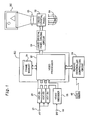
- Fig.1 is a block diagram illustrating the general structure of an image display apparatus as an embodiment according to the present invention.
- the image display apparatus is a computer system including: an analogue image input terminal 10; a digital image input terminal 12; an A-D converter 20; a video decoder (a synchronizing separator circuit) 22; a frame memory 24; a video processor 26; a liquid crystal panel driving circuit 30; a liquid crystal panel 32; and a remote controller controlling circuit 34.
- the frame memory 24 and the video processor 26 are integrated to be an integrated circuit 60 dedicated for image processing.
- This image display apparatus is a projector or so-called projection display apparatus including: an illumination device 50 for illuminating the liquid crystal panel 32; and a projection optical system 52 that projects image light emitted from the liquid crystal panel 32 onto a screen.
- the liquid crystal panel 32 is used as a light valve (a light modulator) that modulates light emitted from the illumination system 50.
- the liquid crystal panel 32, the illumination system 50, and the projection optical system 52 correspond to an "image display section" of the present invention.
- the image display apparatus has three liquid crystal panels 32 corresponding to the three colors R, G, and B. Additionally, each circuit, which will be described later, has a function to process the three components of the image signals corresponding to the three colors.
- the illumination system 50 has a color light separating optical system that separates white light into light of three colors.
- the projection optical system 52 has a synthesis optical system that synthesizes image light of three colors to generate image light representing a color image.
- the optical system structure of such projection display apparatus is described in detail in JPA Hei 8-352003 disclosed by the applicants of the present invention, and further descriptions are omitted here.
- An input image signal is selected from an analogue image signal AV input to an analogue image input terminal 10 and a digital image signal DV input to a digital image input terminal 12.
- the analogue image signal AV is converted by the A-D converter 20 into digital image signals that include image signal components of the three colors.
- Image signals input to the video processor 26 are temporarily written in the frame memory 24, and then read out from the frame memory 24 to be supplied to the liquid crystal panel driving circuit 30.
- the video processor 26 performs various kinds of image processing upon the inputted image signals during the writing and reading.
- the liquid crystal panel driving circuit 30 generates a drive signal for driving the liquid crystal panel 32 in response to the given image signals.
- the liquid crystal panel 32 modulates illumination light in response to the drive signal.
- a user can input with the remote controller 40 set values for various adjustments related to the image display, such as sharpness adjustment, contrast adjustment, and brightness adjustment, which will be described later. Additionally, although not shown, the image display apparatus itself is also equipped with keys or buttons for inputting various set values for image displaying.
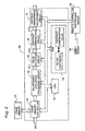
- Fig. 2 is a block diagram illustrating the internal structure of the video processor 26.
- the video processor 26 includes: a frame memory controller 62; an enlargement/reduction processing circuit 64; an image filtering circuit 66; a contrast compensation circuit 68; a contrast/brightness adjustment circuit 70; CPU 72; and RAM 74.
- the frame memory controller 62 controls the writing of a digital image signal DV0 supplied from the A-D converter 20 or the video decoder 22 shown in Fig. 1 into the frame memory 24, and the reading of the digital image signal from the frame memory 24.
- the enlargement/reduction processing circuit 64 has a function to perform enlargement or reduction of the image according to setting by the user, as well as to perform interpolation, if required, while performing the enlargement or the reduction.
- the image filtering circuit 66 is a digital filter for performing sharpness (acutance) adjustment of the image according to the setting by the user.
- the contrast compensation circuit 68 is a circuit for compensating the contrast of the digital image signal that has undergone filter processing.
- the term "contrast compensation” referred to here in the description of the present invention is synonymous with the term “contrast adjustment”. The details of processes in the image filtering circuit 66 and the contrast compensation circuit 68 are described later. Filter coefficients used in the image filtering circuit 66 and compensation values used in the contrast compensation circuit 68 are associated with each other and stored in the RAM 74.
- the contrast/brightness adjustment circuit 70 is a circuit for adjusting contrast and brightness of the image according to the setting by the user.
- the adjustment of contrast in the contrast/brightness adjustment circuit 70 is performed independent of the contrast adjustment performed in the contrast compensation circuit 68.
- Fig. 3 is a block diagram illustrating the internal structure of the image filtering circuit 66.
- the image filtering circuit 66 is a two-dimensional filter constituted by a horizontal filter 80 and a vertical filter 90 which are connected in series.
- the horizontal filter 80 is a three-tap FIR filter (a finite impulse response filter) constituted by two horizontal delay circuits 81, 82, three multipliers 83-85, and an adder 86.
- the vertical filter 90 also has a structure similar to the horizontal filter 80. However, the delay Du of the horizontal delay circuits 81, 82 in the horizontal filter 80 corresponds to one pixel while the delay Dv of the two vertical delay circuits 91, 92 in the vertical filter 90 corresponds to one scanning line.
- Values ku1-ku3 and kv1-kv3, which are multiplied in the multipliers 83-85 and 93-95, respectively, constitute one set of filter coefficients.
- plural sets of filter coefficients are stored for realizing a plurality of filters with different frequency characteristics.
- a low pass filter (smoothing filter) can be realized by the following filter coefficients.
- a high pass filter can be realized by the following filter coefficients.
- each of the horizontal filter 80 and the vertical filter 90 is constituted by a three-tap FIR filter.
- a FIR filter having 16 to 512 taps for example.
- By using a filter with a large number of taps it is possible to realize various filter characteristics appropriate for the sharpness adjustment of the image.
- various image improvement effects including sharpness can be realized by setting up filter coefficients and window functions in an appropriate way.
- the number of taps in the horizontal filter 80 and in the vertical filter 90 may be different to one another. It is also possible to use filters other than FIR filters as image filters.
- a digital image signal DV2 that has undergone filter processing is then adjusted in contrast by the contrast compensation circuit 68.
- Fig. 4 illustrates input/output characteristics (contrast compensation characteristics) of the contrast compensation circuit 68.
- two contrast compensation characteristics C1, C2 with different gradients are indicated with a solid line and a dashed line respectively.
- the contrast compensation characteristics are typically capable of enhancing the contrast of the image. The reason is that, as will be described in the following, the main objective of the contrast compensation circuit 68 is to recover (that is to compensate) the contrast of the image that is lowered during the filter processing.
- contrast compensation circuit 68 It is possible to establish a plurality of contrast compensation characteristics for the contrast compensation circuit 68.
- the plurality of contrast compensation characteristics is indicated by contrast compensation values.
- contrast compensation value in this specification is a value indicating one of the plurality of contrast compensation characteristics available.
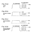
- Figs. 5(a)-5(d) illustrate the relationship between the filter processing and the contrast compensation.
- Fig. 5(a) illustrates a signal waveform of a digital image signal DV input to the image display apparatus.
- the image represented by this image signal DV is assumed to have a DC component region (a region with approximately constant brightness) and AC component regions (regions with abruptly changing brightness). It is also assumed that the greatest and the lowest brightness are 100% and 0% respectively in both the DC component region and the AC component regions.
- the waveform such as illustrated in Fig. 5(a) is the one formed at an output terminal of an image signal supplier device, such as a personal computer that supplies image signals to the image display apparatus.
- This image signal DV decays on passing through various wirings and circuits.
- the image signal DV is input to the image filtering circuit 66, the AC component regions are mainly decayed as illustrated in Fig. 5(b).
- the image signal DV1 shown in Fig. 5(b) is directly used for displaying the image, an image with low sharpness (acutance) will then be observed, for the AC components (especially the components with high frequency) of the signal have decayed. Therefore, the user can adjust sharpness by using the image filtering circuit 66, so that the sharpness in the DC component region and the AC component regions is approximately at an identical level, as shown in Fig. 5(c).
- the filter processing not only varies the sharpness of the image, but also affects contrast and brightness of the image. Concretely, contrast and brightness of the image is reduced as a result of the filter processing, as shown in Fig. 5(c). It is thus possible to adjust the contrast by using the contrast compensation circuit 68, so that the contrast and the brightness after the filter processing can recover to approximately the same level as the original digital image signal DV. As a result of this process, spatial frequency bands are raised by the high pass filter.
- Fig. 6 illustrates a test pattern used in determining a contrast compensation value.
- the test pattern contains a white region and a black region.
- the white region has the greatest brightness, where all the signal values for the three colors RGB of the image signals DV have the greatest value "FF" (in a hexadecimal notation) in its dynamic range.
- the black region has the smallest brightness, where all signal values for three colors RGB of image signals DV have the smallest value "00" in its dynamic range.
- the test pattern shown in Fig. 6 also includes regions with half tones in addition to the white region and the black region, but the half tone regions may be omitted.
- a test pattern such as shown in Fig. 6 is displayed onto a screen SC (Fig. 1), then an illuminance meter is placed approximately at the center of a white region in the test pattern to measure the illuminance.
- the illuminance of the white region on the screen SC is used as an index value that indicates the brightness of the brightest region on the liquid crystal panel 32.
- the set of filter coefficients used in the image filtering circuit 66 is changed, while a contrast compensation value is determined for each set of filter coefficients such that the measured illuminance at the center of the white region is substantially kept unchanged.
- the brightness at the center of the white region in the displayed image can still be substantially kept unchanged.
- the term "being substantially kept unchanged” means that the value is kept unchanged within a range of about ⁇ 5%. It is preferable, however, to maintain the brightness at the center of the white region within a range of about ⁇ 3%.
- the determination of the contrast compensation value is performed such that at least the brightness at the center of the white region is substantially kept unchanged.
- contrast compensation such that the contrast (a ratio of greatest brightness to smallest brightness) itself is substantially kept unchanged instead of maintaining brightness of the white region. It is most preferable to perform the contrast compensation such that the brightness of the white region and the contrast (a ratio of greatest brightness to smallest brightness) are both substantially kept unchanged.
- the brightness at the center may not be substantially kept unchanged despite the contrast compensation.
- the reason is that in regions smaller than the substantial filter size of the image filter as a spatial filter, brightness therein is considerably affected by brightness in adjacent regions, so that brightness values after the contrast compensation would vary in response to the brightness of adjacent regions.
- substantially filter size means a size of filter that is constituted by pixels with non-zero filter coefficients.
- the white regions where brightness is substantially kept unchanged after the contrast compensation are regions which are larger than the filter size of the image filter.
- the image filter illustrated in Fig.3 is a spatial filter with 3x3 pixels.
- the contrast compensation will substantially maintain brightness in the regions which are larger than 3x3 pixels.
- brightness at the center of white regions larger than about 80x80 pixels will be substantially kept unchanged.
- the sizes of the white region and the black region of the test pattern are larger than the substantial filter size, which is the size of the image filter constructed as a spatial filter.
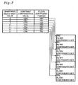
- Fig. 7 illustrates the relationship between plural sets of filter coefficients stored in RAM 74 (Fig. 2) and contrast compensation values.
- Sharpness adjustment values are set by a user with the remote controller 40. In the example illustrated in Fig. 7, it is assumed that the user can set the sharpness adjustment value at one of seven levels ranging from -3 to +3. If the sharpness adjustment value is -3 for example, the image filtering circuit 66 functions as a smoothing filter that lowers sharpness of images. On the other hand, if the sharpness adjustment value is +3, the image filtering circuit 66 functions as a sharpness emphasis filter that enhances the sharpness of images.
- the seven levels of the sharpness adjustment value are related to seven contrast compensation values CP0-CP6, respectively, and to seven filter coefficient pointers FP0-FP6, respectively, that indicate the addresses of seven sets of filter coefficients.
- Fig. 8 illustrates an example of a setup menu for adjustment values, which is used by a user to adjust display conditions.
- a user can operate the remote controller 40 to display the setup menu for adjustment values such as shown in Fig. 8, in order to independently set brightness, contrast, and sharpness of the image.
- one sharpness adjustment value is selected by a user
- one set of filter coefficients (Fig. 7) is then selected by a filter coefficient pointer corresponding to the adjustment value, and the selected set of filter coefficients is set in the image filtering circuit 66.
- the contrast compensation value that corresponds to the sharpness adjustment value is set in the contrast compensation circuit 68.
- the contrast compensation value is determined such that the brightness of white regions within an image are substantially kept unchanged regardless of the filter coefficients used. Therefore, even if the sharpness adjustment value is changed by a user, it appears that the contrast and the brightness of the whole image is not much changed while only the sharpness is changed. It is thus possible to display a high quality image with appropriate sharpness without much affecting the contrast and the brightness of the image.
- Some display images do not include white regions with sufficiently large areas. In such cases, the brightness of the brightest region in the display image will be kept unchanged regardless of the sharpness adjustment if the region has a sufficiently large size larger than the filter size of the image filter.
- a user can also set a contrast adjustment value and a brightness adjustment value in the contrast/brightness adjustment circuit 70 (Fig. 2), using the setup menu for adjustment values shown in Fig. 8.
- the contrast adjustment in the contrast/brightness adjustment circuit 70 is performed independent of the contrast adjustment in the contrast compensation circuit 68.
- the user thus can voluntarily adjust the contrast of the image using the contrast/brightness adjustment circuit 70. In this way, the user can independently adjust the sharpness, brightness, and contrast of the image, respectively, to display an image with high image qualities.
- the brightness is kept unchanged at the center of high-brightness regions with sufficiently large areas in the displayed image regardless of the setting of the sharpness adjustment. Therefore, it is possible to enhance image quality through the sharpness adjustment without significantly affecting the contrast and brightness of the image.
- the spatial frequency of a region decreases as the region becomes larger, and the spatial frequency increases as the region becomes smaller. Therefore, through the filter processing using a high pass filter in the above-mentioned example, brightness is kept unchanged in the regions with a low spatial frequency while edges and borders are emphasized in the regions with a high spatial frequency.
- the present invention is applicable to various types of image display apparatuses such as projection type display apparatuses and direct-view type display apparatuses, and also to image processing devices therefor.
Description
- The present invention relates to a technology for adjusting quality of a displayed image.
- Sharpness adjustment is one well-known method of image processing. In some image display apparatuses such as projectors, the sharpness adjustment can be setup by users. When performing the sharpness adjustment, image quality can be improved by enhancing the sharpness of the diffused image, or by removing high frequency noises at the more or less sacrifice of sharpness (acutance).
- Various filters with different frequency characteristics are used in the sharpness adjustment, such as smoothing filter, differential filter. For example, the smoothing filter is used to remove high frequency noises contained in image, and the differential filter is used to punctuate edges of image by amplifying high frequency components.
- However, in typical sharpness adjustment, not only the sharpness of the image is adjusted, but contrast and brightness of the image is also affected, too. Accordingly, there arises a problem that when the set value of sharpness adjustment is changed by the user, the contrast and brightness of the image will be varied, too. This problem is not limited to the case of performing sharpness adjustment, and is a common problem found in adjustments of various image qualities other than contrast and brightness.
- For example, US 5,003,394 discloses a dymamic video system that minimises "white spot blooming" without adversely effecting the sharpness and brightness of the reproduced image by using an automatic contrast control processing section and a "white stretch" processing section.
- The present invention is made to solve the above-mentioned problem of the prior art, and an object thereof is to provide a new technology that can reduce the influence which image quality adjustment makes upon contrast or brightness of the image.
- In order to solve at least part of the above-mentioned object, the present invention performs an adjustment of specific image quality other than contrast and brightness according to a set value setup by the user. At the same time, the present invention also compensates contrast of the image.
- According to an aspect of the present invention there is provided an image processing device as claimed in
claim 1, whilst according to another aspect of the present invention there is provided an image processing method as claimed in claim 6. - Preferably, contrast compensation is performed such that brightness is substantially kept unchanged at a center of a specific color region which is larger than a predetermined size, regardless of the set value of the image quality adjustment. The "contrast compensation" here is synonymous with "contrast adjustment".
- By performing such contrast compensation, preferably brightness at the center of the specific color region is substantially kept unchanged regardless of the set value of the image quality adjustment, and therefore the influence of image quality adjustment upon contrast and brightness of the image is suppressed in low level.
- In a preferred embodiment of the present invention, brightness of the region which is smaller than the predetermined size or which is not of the specific color is permitted to vary along with the change of the set value of image quality adjustment. This is also the same with periphery portions of the specific color region larger than the predetermined size. However, at the center of the sufficiently large specific color region larger than the predetermined size, brightness therein is substantially kept unchanged even when the set value of the image quality adjustment is changed. Whether or not a region of the specific color within an image corresponds to "a specific color region larger than a predetermined size" can be determined by examining whether or not the brightness at its center is substantially kept unchanged when the set value of the image quality adjustment is changed.
- The specific image quality adjustment is sharpness adjustment. In sharpness adjustment, contrast and brightness of the image tend to vary easily, so the above-mentioned contrast compensation will attain excellent effects.
- It is contemplated, however, in arrangements that do not fall within the scope of the claims that the specific image quality adjustment is any image quality other than 3 contrast and brightness.
- The specific color is white for example. Because the white color has the greatest displayable brightness, it is thus possible to suppress changes of contrast and brightness in other regions with different colors by performing the contrast compensation such that the brightness at the centers of the white regions is substantially kept unchanged.
- The image quality adjustment is performed by selecting one of a plurality of filters with different frequency characteristics, according to the set value of image quality adjustment, and then performing a filtering process of the image by using the selected filter. Additionally, the contrast compensation is performed upon the image that has undergone the filter processing, with a contrast compensation value related to the selected filter in advance.
- In this way, the contrast compensation can be easily performed such that brightness in the specific color region within the image is preferably substantially kept unchanged.
- It is preferable that the contrast adjustment of the image is carried out independently of the contrast compensation.
- In this way, it is possible to independently perform contrast adjustment and specific adjustment of image quality other than contrast and brightness, thereby enhancing the image quality of the image.
- The present invention can be realized in various ways including: a method and an apparatus for image processing; a method and an apparatus for displaying an image; a computer program for implementing functions of the methods and the apparatus; a recording medium on which the computer program is stored; a data signal embodied in a carrier wave including the computer program.
- Various embodiments of the present invention will now be described, by way of example only, and with reference to the accompanying drawings in which:
- Fig. 1 is a block diagram illustrating the general structure of an image display apparatus as an embodiment according to the present invention;
- Fig. 2 is a block diagram illustrating the internal structure of a
video processor 26; - Fig. 3 is a block diagram illustrating the internal structure of an
image filter circuit 66; - Fig. 4 illustrates the input output characteristics of the
contrast compensation circuit 68; - Figs. 5(a)-5(d) illustrate the relationship between filter processing and contrast compensation;
- Fig. 6 illustrates a test pattern used when determining a contrast compensation value;
- Fig. 7 illustrates the relationship between each set of filter coefficients stored in the RAM 74 (Fig. 2) and a contrast compensation value; and
- Fig. 8 illustrates an example of a setup menu for adjustment values used by a user to adjust display conditions.
- Fig.1 is a block diagram illustrating the general structure of an image display apparatus as an embodiment according to the present invention. The image display apparatus is a computer system including: an analogue
image input terminal 10; a digitalimage input terminal 12; anA-D converter 20; a video decoder (a synchronizing separator circuit) 22; aframe memory 24; avideo processor 26; a liquid crystalpanel driving circuit 30; aliquid crystal panel 32; and a remotecontroller controlling circuit 34. Theframe memory 24 and thevideo processor 26 are integrated to be an integratedcircuit 60 dedicated for image processing. - This image display apparatus is a projector or so-called projection display apparatus including: an
illumination device 50 for illuminating theliquid crystal panel 32; and a projectionoptical system 52 that projects image light emitted from theliquid crystal panel 32 onto a screen. Theliquid crystal panel 32 is used as a light valve (a light modulator) that modulates light emitted from theillumination system 50. In this projection display apparatus, theliquid crystal panel 32, theillumination system 50, and the projectionoptical system 52 correspond to an "image display section" of the present invention. - Although not illustrated, the image display apparatus has three
liquid crystal panels 32 corresponding to the three colors R, G, and B. Additionally, each circuit, which will be described later, has a function to process the three components of the image signals corresponding to the three colors. Theillumination system 50 has a color light separating optical system that separates white light into light of three colors. Additionally, the projectionoptical system 52 has a synthesis optical system that synthesizes image light of three colors to generate image light representing a color image. The optical system structure of such projection display apparatus is described in detail in JPA Hei 8-352003 disclosed by the applicants of the present invention, and further descriptions are omitted here. - An input image signal is selected from an analogue image signal AV input to an analogue
image input terminal 10 and a digital image signal DV input to a digitalimage input terminal 12. The analogue image signal AV is converted by theA-D converter 20 into digital image signals that include image signal components of the three colors. - Image signals input to the
video processor 26 are temporarily written in theframe memory 24, and then read out from theframe memory 24 to be supplied to the liquid crystalpanel driving circuit 30. Thevideo processor 26 performs various kinds of image processing upon the inputted image signals during the writing and reading. The liquid crystalpanel driving circuit 30 generates a drive signal for driving theliquid crystal panel 32 in response to the given image signals. Theliquid crystal panel 32 modulates illumination light in response to the drive signal. - A user can input with the
remote controller 40 set values for various adjustments related to the image display, such as sharpness adjustment, contrast adjustment, and brightness adjustment, which will be described later. Additionally, although not shown, the image display apparatus itself is also equipped with keys or buttons for inputting various set values for image displaying. - Fig. 2 is a block diagram illustrating the internal structure of the
video processor 26. Thevideo processor 26 includes: aframe memory controller 62; an enlargement/reduction processing circuit 64; animage filtering circuit 66; acontrast compensation circuit 68; a contrast/brightness adjustment circuit 70; CPU 72; andRAM 74. - The
frame memory controller 62 controls the writing of a digital image signal DV0 supplied from theA-D converter 20 or thevideo decoder 22 shown in Fig. 1 into theframe memory 24, and the reading of the digital image signal from theframe memory 24. The enlargement/reduction processing circuit 64 has a function to perform enlargement or reduction of the image according to setting by the user, as well as to perform interpolation, if required, while performing the enlargement or the reduction. - The
image filtering circuit 66 is a digital filter for performing sharpness (acutance) adjustment of the image according to the setting by the user. Thecontrast compensation circuit 68 is a circuit for compensating the contrast of the digital image signal that has undergone filter processing. The term "contrast compensation" referred to here in the description of the present invention is synonymous with the term "contrast adjustment". The details of processes in theimage filtering circuit 66 and thecontrast compensation circuit 68 are described later. Filter coefficients used in theimage filtering circuit 66 and compensation values used in thecontrast compensation circuit 68 are associated with each other and stored in theRAM 74. - The contrast/
brightness adjustment circuit 70 is a circuit for adjusting contrast and brightness of the image according to the setting by the user. The adjustment of contrast in the contrast/brightness adjustment circuit 70 is performed independent of the contrast adjustment performed in thecontrast compensation circuit 68. - Fig. 3 is a block diagram illustrating the internal structure of the
image filtering circuit 66. Theimage filtering circuit 66 is a two-dimensional filter constituted by ahorizontal filter 80 and avertical filter 90 which are connected in series. Thehorizontal filter 80 is a three-tap FIR filter (a finite impulse response filter) constituted by twohorizontal delay circuits adder 86. Thevertical filter 90 also has a structure similar to thehorizontal filter 80. However, the delay Du of thehorizontal delay circuits horizontal filter 80 corresponds to one pixel while the delay Dv of the twovertical delay circuits vertical filter 90 corresponds to one scanning line. - Values ku1-ku3 and kv1-kv3, which are multiplied in the multipliers 83-85 and 93-95, respectively, constitute one set of filter coefficients. In the
RAM 74 shown in Fig. 2, plural sets of filter coefficients are stored for realizing a plurality of filters with different frequency characteristics. - It is possible to realize various image filters with different frequency characteristics by changing the filter coefficients ku1-ku3 and kv1-kv3. For example, a low pass filter (smoothing filter) can be realized by the following filter coefficients.

and
- A high pass filter can be realized by the following filter coefficients.


- In the example shown in Fig. 3, each of the
horizontal filter 80 and thevertical filter 90 is constituted by a three-tap FIR filter. For practical applications, however, it is preferable to use a FIR filter having 16 to 512 taps for example. By using a filter with a large number of taps, it is possible to realize various filter characteristics appropriate for the sharpness adjustment of the image. When using a filter with a large number of taps, various image improvement effects including sharpness can be realized by setting up filter coefficients and window functions in an appropriate way. The number of taps in thehorizontal filter 80 and in thevertical filter 90 may be different to one another. It is also possible to use filters other than FIR filters as image filters. - A digital image signal DV2 that has undergone filter processing is then adjusted in contrast by the
contrast compensation circuit 68. Fig. 4 illustrates input/output characteristics (contrast compensation characteristics) of thecontrast compensation circuit 68. In Fig. 4, two contrast compensation characteristics C1, C2 with different gradients are indicated with a solid line and a dashed line respectively. As can be understood from the illustration, the contrast compensation characteristics are typically capable of enhancing the contrast of the image. The reason is that, as will be described in the following, the main objective of thecontrast compensation circuit 68 is to recover (that is to compensate) the contrast of the image that is lowered during the filter processing. - It is possible to establish a plurality of contrast compensation characteristics for the
contrast compensation circuit 68. The plurality of contrast compensation characteristics is indicated by contrast compensation values. The term "contrast compensation value" in this specification is a value indicating one of the plurality of contrast compensation characteristics available. - Figs. 5(a)-5(d) illustrate the relationship between the filter processing and the contrast compensation. Fig. 5(a) illustrates a signal waveform of a digital image signal DV input to the image display apparatus. The image represented by this image signal DV is assumed to have a DC component region (a region with approximately constant brightness) and AC component regions (regions with abruptly changing brightness). It is also assumed that the greatest and the lowest brightness are 100% and 0% respectively in both the DC component region and the AC component regions. To be more exact, the waveform such as illustrated in Fig. 5(a) is the one formed at an output terminal of an image signal supplier device, such as a personal computer that supplies image signals to the image display apparatus.
- This image signal DV decays on passing through various wirings and circuits. When the image signal DV is input to the
image filtering circuit 66, the AC component regions are mainly decayed as illustrated in Fig. 5(b). Suppose the image signal DV1 shown in Fig. 5(b) is directly used for displaying the image, an image with low sharpness (acutance) will then be observed, for the AC components (especially the components with high frequency) of the signal have decayed. Therefore, the user can adjust sharpness by using theimage filtering circuit 66, so that the sharpness in the DC component region and the AC component regions is approximately at an identical level, as shown in Fig. 5(c). However, the filter processing not only varies the sharpness of the image, but also affects contrast and brightness of the image. Concretely, contrast and brightness of the image is reduced as a result of the filter processing, as shown in Fig. 5(c). It is thus possible to adjust the contrast by using thecontrast compensation circuit 68, so that the contrast and the brightness after the filter processing can recover to approximately the same level as the original digital image signal DV. As a result of this process, spatial frequency bands are raised by the high pass filter. - Fig. 6 illustrates a test pattern used in determining a contrast compensation value. The test pattern contains a white region and a black region. The white region has the greatest brightness, where all the signal values for the three colors RGB of the image signals DV have the greatest value "FF" (in a hexadecimal notation) in its dynamic range. The black region has the smallest brightness, where all signal values for three colors RGB of image signals DV have the smallest value "00" in its dynamic range. The test pattern shown in Fig. 6 also includes regions with half tones in addition to the white region and the black region, but the half tone regions may be omitted.
- In determining a contrast compensation value, a test pattern such as shown in Fig. 6 is displayed onto a screen SC (Fig. 1), then an illuminance meter is placed approximately at the center of a white region in the test pattern to measure the illuminance. The illuminance of the white region on the screen SC is used as an index value that indicates the brightness of the brightest region on the
liquid crystal panel 32. Next, the set of filter coefficients used in theimage filtering circuit 66 is changed, while a contrast compensation value is determined for each set of filter coefficients such that the measured illuminance at the center of the white region is substantially kept unchanged. In this way, even when the sharpness adjustment value is changed by the user and the filter coefficients are also varied accordingly, the brightness at the center of the white region in the displayed image can still be substantially kept unchanged. The term "being substantially kept unchanged" means that the value is kept unchanged within a range of about ±5%. It is preferable, however, to maintain the brightness at the center of the white region within a range of about ±3%. - It is possible to determine the contrast compensation value such that brightness at the center of the black region is substantially kept unchanged. In the black region, however, it is difficult to distinguish little differences of brightness with the naked eye. Therefore, the determination of the contrast compensation value is performed such that at least the brightness at the center of the white region is substantially kept unchanged.
- However, it is also possible to perform contrast compensation such that the contrast (a ratio of greatest brightness to smallest brightness) itself is substantially kept unchanged instead of maintaining brightness of the white region. It is most preferable to perform the contrast compensation such that the brightness of the white region and the contrast (a ratio of greatest brightness to smallest brightness) are both substantially kept unchanged.
- On the other hand, in regions with white color but of substantially small size, the brightness at the center may not be substantially kept unchanged despite the contrast compensation. The reason is that in regions smaller than the substantial filter size of the image filter as a spatial filter, brightness therein is considerably affected by brightness in adjacent regions, so that brightness values after the contrast compensation would vary in response to the brightness of adjacent regions. The term "substantial filter size" referred to here means a size of filter that is constituted by pixels with non-zero filter coefficients. The white regions where brightness is substantially kept unchanged after the contrast compensation are regions which are larger than the filter size of the image filter. For example, the image filter illustrated in Fig.3 is a spatial filter with 3x3 pixels. When this image filter is used, the contrast compensation will substantially maintain brightness in the regions which are larger than 3x3 pixels. In the case of using an FIR filter having about eighty-taps as a horizontal or a vertical filter, brightness at the center of white regions larger than about 80x80 pixels will be substantially kept unchanged.
- As can be understood from the above descriptions, at peripheries of each white region of a sufficiently large size, there is some possibility that the brightness therein is not kept unchanged even through the contrast compensation. Furthermore, the brightness of non-white regions of a sufficiently large size may not be kept unchanged. Practically speaking, however, the brightness is often kept unchanged even at the center of non-white regions.
- For the same reason as stated above, it is also preferable to set the sizes of the white region and the black region of the test pattern larger than the substantial filter size, which is the size of the image filter constructed as a spatial filter.
- Fig. 7 illustrates the relationship between plural sets of filter coefficients stored in RAM 74 (Fig. 2) and contrast compensation values. Sharpness adjustment values are set by a user with the
remote controller 40. In the example illustrated in Fig. 7, it is assumed that the user can set the sharpness adjustment value at one of seven levels ranging from -3 to +3. If the sharpness adjustment value is -3 for example, theimage filtering circuit 66 functions as a smoothing filter that lowers sharpness of images. On the other hand, if the sharpness adjustment value is +3, theimage filtering circuit 66 functions as a sharpness emphasis filter that enhances the sharpness of images. The seven levels of the sharpness adjustment value are related to seven contrast compensation values CP0-CP6, respectively, and to seven filter coefficient pointers FP0-FP6, respectively, that indicate the addresses of seven sets of filter coefficients. - Fig. 8 illustrates an example of a setup menu for adjustment values, which is used by a user to adjust display conditions. In this example, a user can operate the
remote controller 40 to display the setup menu for adjustment values such as shown in Fig. 8, in order to independently set brightness, contrast, and sharpness of the image. - When one sharpness adjustment value is selected by a user, one set of filter coefficients (Fig. 7) is then selected by a filter coefficient pointer corresponding to the adjustment value, and the selected set of filter coefficients is set in the
image filtering circuit 66. At the same time, the contrast compensation value that corresponds to the sharpness adjustment value is set in thecontrast compensation circuit 68. As a result, the filter processing and the contrast compensation of the image are performed using the set of filter coefficients and the contrast compensation value that are associated with each other in advance. - As described with reference to Fig. 6, the contrast compensation value is determined such that the brightness of white regions within an image are substantially kept unchanged regardless of the filter coefficients used. Therefore, even if the sharpness adjustment value is changed by a user, it appears that the contrast and the brightness of the whole image is not much changed while only the sharpness is changed. It is thus possible to display a high quality image with appropriate sharpness without much affecting the contrast and the brightness of the image.
- Some display images do not include white regions with sufficiently large areas. In such cases, the brightness of the brightest region in the display image will be kept unchanged regardless of the sharpness adjustment if the region has a sufficiently large size larger than the filter size of the image filter.
- Furthermore, a user can also set a contrast adjustment value and a brightness adjustment value in the contrast/brightness adjustment circuit 70 (Fig. 2), using the setup menu for adjustment values shown in Fig. 8. The contrast adjustment in the contrast/
brightness adjustment circuit 70 is performed independent of the contrast adjustment in thecontrast compensation circuit 68. The user thus can voluntarily adjust the contrast of the image using the contrast/brightness adjustment circuit 70. In this way, the user can independently adjust the sharpness, brightness, and contrast of the image, respectively, to display an image with high image qualities. - As described above, according to the above-mentioned embodiment, when a user adjusts sharpness, the brightness is kept unchanged at the center of high-brightness regions with sufficiently large areas in the displayed image regardless of the setting of the sharpness adjustment. Therefore, it is possible to enhance image quality through the sharpness adjustment without significantly affecting the contrast and brightness of the image.
- In general, the spatial frequency of a region decreases as the region becomes larger, and the spatial frequency increases as the region becomes smaller. Therefore, through the filter processing using a high pass filter in the above-mentioned example, brightness is kept unchanged in the regions with a low spatial frequency while edges and borders are emphasized in the regions with a high spatial frequency.
- The present invention is not limited to the above-mentioned examples or embodiments, and it may be implemented in various embodiments without departing from the scope of the invention as set forth in the accompanying claims. For example, it is possible to make modifications as follows.
- (1) In the above embodiments, the contrast compensation is performed along with the sharpness adjustment, but it is also contemplated, in arrangements that do not fall within the scope of the claims, that other image quality adjustments other than the sharpness adjustment can be performed. In other words, contrast compensation may be performed along with specific adjustment of image quality other than contrast and brightness.
- (2) In the above-mentioned embodiments, the contrast compensation is performed such that brightness is kept unchanged at the center of white regions. Alternatively, it may be performed such that brightness is kept unchanged at the center of a specific color region other than white (red for example). That is, the contrast compensation may be performed such that the brightness is kept unchanged at the center of a specific color region which is larger than a predetermined size.
- (3) Although a two-dimensional image filter is used in the above-mentioned embodiment, it is also possible to use a one-dimensional image filter. In addition, it is also possible to adapt various structures as a filter other than the simple FIR filter. Furthermore, a digital filter is used in the above examples, but it is also contemplated that an analogue filter can be used.
- (4) Although the structure of the projection display apparatus employing transmission-type liquid crystal panels is described in the above embodiment, embodiments of the present invention are also applicable to other types of projection display apparatus. Other types of projection display apparatus include ones employing a reflection-type liquid crystal panel, ones employing Micro-Mirror Device (trademark of Texas Instruments), and ones employing CRT.
Embodiments of the present invention are also applicable to image display apparatus other than the projection display apparatus. For example, embodiments of the present invention are also applicable to image display apparatus with a direct-view image display device, such as a liquid crystal panel, a plasma display panel, or CRT, or to an image display apparatus, such as a head mount display device, that enlarges an image such that an enlarged virtual image is observed by a user. - (5) Part of the structure realized by hardware in the above embodiments may be implemented with software, and, on the contrary, part of the structure realized by software may be implemented by hardware. For example, it is possible to implement the functions of the
image filtering circuit 66 and thecontrast compensation circuit 68 shown in Fig. 2 by means of computer programs.
Such computer programs are provided in a form stored on a recording medium. The "recording medium" includes various computer readable mediums, such as floppy disks, CD-ROMs, magneto-optic disks, IC cards, ROM cartridges, punch cards, printed matter with codes such as bar codes printed thereon, internal storages (memories such as RAM or ROM) and external storages of computers, and carrier waves for communication. - (6) The functions of the
image filtering circuit 66 and thecontrast compensation circuit 68 may also be realized by one circuit or one program. That is, in embodiments of the present invention, contrast can be compensated such that brightness is substantially kept unchanged at the center of a specific color region larger than a predetermined size, regardless of the set value of a specific image adjustment other than contrast and brightness adjustments. - The present invention is applicable to various types of image display apparatuses such as projection type display apparatuses and direct-view type display apparatuses, and also to image processing devices therefor.
Claims (10)
- An image processing device, comprising:a filter section (66) for performing filter processing of an image so as to reduce the DC component of the image signal (DV1), thereby effecting sharpness adjustment of the image signal (DV1); anda contrast compensation section (68) for enhancing both the DC and AC components of the image signal (DV2) so as to compensate the reduction of the DC component by the filter processing, thereby effecting sharpness adjustment of the image signal (DV2) regardless of the magnitude of the sharpness adjustment;wherein the filter section (66) is arranged to select one of a plurality of filters with different frequency characteristics according to a specified value of the sharpness adjustment, an to execute the filter processing with the selected filter to effect the sharpness adjustment; and
the contrast compensation section (68) is arranged to execute the contrast compensation of the filtered image using a contrast compensation value (CP0-CP6) which is related in advance to the selected filter. - An image processing device in accordance with claim 1, wherein the contrast compensation section (68) is arranged to perform contrast compensation such that brightness is kept unchanged at a center of a specific color region larger than a predetermined size within an image that has undergone the filter processing, regardless of which filter is selected from the plurality of filters.
- An image processing device in accordance with claim 2, wherein said specific color is white.
- An image processing device in accordance with claim 1, 2 or 3, further comprising a contrast adjustment section (70) that is arranged to perform contrast adjustment of the image independently of the contrast compensation section (68).
- An image display apparatus, comprising:an image display device (60,50,52) for displaying images;a setting section (40,34) for allowing a user to specify a sharpness adjustment value; andan image processing device according to any one of claims 1 to 4.
- An imaging processing method, comprising the steps of:(a) performing filter processing of an image so as to reduce the DC component of the image signal (DV1), thereby effecting sharpness adjustment of the image signal (DV1); and(b) enhancing both the DC and AC components of the image signal (DV2) so as to compensate the reduction of the DC component by the filter processing, thereby effecting sharpness adjustment of the image signal (DV2) regardless of the magnitude of the sharpness adjustment;wherein the step (a) includes selecting one of a plurality of filters with different frequency characteristics according to a specified value of the sharpness adjustment, and executes the filter processing with the selected filter to effect the sharpness adjustment; and
the step (b) includes executing the contrast compensation of the filtered image using a contrast compensation value (CP0-CP6) which is related in advance to the selected filter - An imaging processing method in accordance with claim 6, wherein the step (b) includes executing contrast compensation such that brightness is kept unchanged at a center of a specific color region larger than a predetermined size within an image that has undergone the filter processing, regardless of which filter is selected from the plurality of filters.
- An imaging processing method in accordance with claim 7, wherein said specific color is white.
- An image processing method in accordance with claims 6, 7 or 8, further comprising the step of performing contrast adjustment of the image independently of the contrast compensation in the step (b).
- An image display method comprising the steps of:specifying a sharpness adjustment value; andexecuting the steps (a) and (b) of the image processing method according to any one of claims 6 to 9.
Applications Claiming Priority (3)
| Application Number | Priority Date | Filing Date | Title |
|---|---|---|---|
| JP15902199 | 1999-06-07 | ||
| JP15902199A JP3649043B2 (en) | 1999-06-07 | 1999-06-07 | Image display apparatus and method, and image processing apparatus and method |
| PCT/JP2000/003629 WO2000075916A1 (en) | 1999-06-07 | 2000-06-02 | Image displaying apparatus and method, and image processing device and method |
Publications (3)
| Publication Number | Publication Date |
|---|---|
| EP1117088A1 EP1117088A1 (en) | 2001-07-18 |
| EP1117088A4 EP1117088A4 (en) | 2004-11-03 |
| EP1117088B1 true EP1117088B1 (en) | 2007-03-07 |
Family
ID=15684533
Family Applications (1)
| Application Number | Title | Priority Date | Filing Date |
|---|---|---|---|
| EP00935542A Expired - Lifetime EP1117088B1 (en) | 1999-06-07 | 2000-06-02 | Image displaying apparatus and method, and image processing device and method |
Country Status (8)
| Country | Link |
|---|---|
| US (2) | US7570237B2 (en) |
| EP (1) | EP1117088B1 (en) |
| JP (1) | JP3649043B2 (en) |
| KR (1) | KR100370885B1 (en) |
| CN (1) | CN1153186C (en) |
| DE (1) | DE60033779T2 (en) |
| TW (1) | TW468335B (en) |
| WO (1) | WO2000075916A1 (en) |
Cited By (1)
| Publication number | Priority date | Publication date | Assignee | Title |
|---|---|---|---|---|
| CN100511585C (en) * | 2002-06-26 | 2009-07-08 | 东京应化工业株式会社 | Method for forming fine pattern |
Families Citing this family (33)
| Publication number | Priority date | Publication date | Assignee | Title |
|---|---|---|---|---|
| JP3649043B2 (en) * | 1999-06-07 | 2005-05-18 | セイコーエプソン株式会社 | Image display apparatus and method, and image processing apparatus and method |
| US6812045B1 (en) | 2000-09-20 | 2004-11-02 | Kla-Tencor, Inc. | Methods and systems for determining a characteristic of a specimen prior to, during, or subsequent to ion implantation |
| US6493083B2 (en) * | 2000-12-15 | 2002-12-10 | Xerox Corporation | Method for measuring color registration and determining registration error in marking platform |
| US7191402B2 (en) * | 2001-05-10 | 2007-03-13 | Samsung Electronics Co., Ltd. | Method and apparatus for adjusting contrast and sharpness for regions in a display device |
| US7956823B2 (en) | 2001-05-30 | 2011-06-07 | Sharp Kabushiki Kaisha | Color display device, color compensation method, color compensation program, and storage medium readable by computer |
| JP3679060B2 (en) * | 2001-05-30 | 2005-08-03 | シャープ株式会社 | Color display device |
| JP3664114B2 (en) * | 2001-07-16 | 2005-06-22 | セイコーエプソン株式会社 | Image processing of images projected by projectors |
| DE10202163A1 (en) | 2002-01-22 | 2003-07-31 | Bosch Gmbh Robert | Process and device for image processing and night vision system for motor vehicles |
| JP2003283873A (en) * | 2002-03-20 | 2003-10-03 | Sanyo Electric Co Ltd | Contour enhancement circuit |
| US7158102B2 (en) * | 2002-04-26 | 2007-01-02 | Candescent Technologies Corporation | System and method for recalibrating flat panel field emission displays |
| EP1391866A1 (en) * | 2002-08-23 | 2004-02-25 | Deutsche Thomson Brandt | Adaptive noise reduction for digital display panels |
| US7755657B2 (en) | 2003-06-12 | 2010-07-13 | Micronic Laser Systems Ab | Method for high precision printing of patterns |
| US7266229B2 (en) * | 2003-07-24 | 2007-09-04 | Carestream Health, Inc. | Method for rendering digital radiographic images for display based on independent control of fundamental image quality parameters |
| CN100405455C (en) * | 2004-02-23 | 2008-07-23 | 鸿富锦精密工业(深圳)有限公司 | Set and method for adjusting brightness and contrast |
| JP4387220B2 (en) * | 2004-02-24 | 2009-12-16 | 株式会社日立製作所 | Image display method and apparatus |
| JP4677343B2 (en) | 2005-01-14 | 2011-04-27 | キヤノン株式会社 | Image display apparatus and method |
| CN100524447C (en) * | 2005-01-14 | 2009-08-05 | 佳能株式会社 | Display apparatus and its control method |
| US7589781B2 (en) * | 2005-01-26 | 2009-09-15 | Omnivision Technologies, Inc. | Automatic focus for image sensors |
| JP2006208687A (en) * | 2005-01-27 | 2006-08-10 | Konica Minolta Photo Imaging Inc | Video control system for head-mounted display |
| JP2006287636A (en) * | 2005-03-31 | 2006-10-19 | Pioneer Electronic Corp | Image quality adjustment apparatus, image quality adjustment method, and display apparatus |
| KR100705109B1 (en) * | 2005-04-22 | 2007-04-06 | 엘지전자 주식회사 | Method for controlling picture element of image display device |
| JP2007180641A (en) * | 2005-12-27 | 2007-07-12 | Sony Corp | Imaging apparatus and display method of imaging apparatus |
| JP2007206738A (en) * | 2006-01-30 | 2007-08-16 | Kyocera Corp | Imaging device and method |
| JP4816563B2 (en) * | 2006-07-06 | 2011-11-16 | セイコーエプソン株式会社 | Image display system |
| JP4645960B2 (en) * | 2006-12-22 | 2011-03-09 | 株式会社デンソー | In-vehicle display device |
| JP4957960B2 (en) * | 2007-01-29 | 2012-06-20 | ソニー株式会社 | Image processing apparatus, image processing method, and program |
| KR101411324B1 (en) * | 2007-08-14 | 2014-06-25 | 삼성전자주식회사 | Method of displaying images and Display apparatus applying the same |
| JP5195250B2 (en) * | 2008-10-03 | 2013-05-08 | ソニー株式会社 | Image display system and image display apparatus |
| FR2938685B1 (en) | 2008-11-14 | 2016-12-23 | Johnson Controls Tech Cy | METHOD FOR CALIBRATING ITERATION DISPLAY DEVICE TO OPTIMIZE ELECTRICAL STEERING VOLTAGE OF THE DISPLAY DEVICE |
| US20100207865A1 (en) * | 2009-02-19 | 2010-08-19 | Zoran Corporation | Systems and methods for display device backlight compensation |
| JP5282833B1 (en) * | 2012-03-27 | 2013-09-04 | 富士ゼロックス株式会社 | COLOR ADJUSTMENT DEVICE, COLOR ADJUSTMENT SYSTEM, AND PROGRAM |
| JP6729368B2 (en) * | 2014-03-31 | 2020-07-22 | ソニー株式会社 | Image processing apparatus, image processing method, and program |
| CN106970770B (en) * | 2017-03-31 | 2020-08-25 | 联想(北京)有限公司 | Display adjustment method, electronic equipment and device |
Family Cites Families (12)
| Publication number | Priority date | Publication date | Assignee | Title |
|---|---|---|---|---|
| JPS5961283A (en) * | 1982-09-30 | 1984-04-07 | Victor Co Of Japan Ltd | Filter circuit for signal processing |
| US5003394A (en) * | 1989-08-25 | 1991-03-26 | Rca Licensing Corporation | Dynamic video system including automatic contrast and "white-stretch" processing sections |
| CA2040672C (en) * | 1990-04-26 | 1995-05-30 | Masaaki Kanashiki | Image signal processing apparatus |
| JP2599020B2 (en) * | 1990-07-19 | 1997-04-09 | 松下電器産業株式会社 | Black level correction circuit |
| JPH0575899A (en) * | 1991-09-11 | 1993-03-26 | Mitsubishi Electric Corp | Controur compensation circuit |
| EP0784399B1 (en) * | 1994-09-30 | 2006-04-12 | Matsushita Electric Industrial Co., Ltd. | Image pickup device |
| EP0756246B1 (en) * | 1995-07-25 | 2002-09-25 | Kabushiki Kaisha Toyota Chuo Kenkyusho | Image processing device |
| JPH1039772A (en) * | 1996-07-29 | 1998-02-13 | Mitsubishi Electric Corp | Projection type liquid crystal display device |
| US6330038B1 (en) * | 1997-03-31 | 2001-12-11 | Compaq Computer Corporation | Video sharpness control device and method |
| US6281933B1 (en) * | 1997-12-11 | 2001-08-28 | Chrontel, Inc. | Images in interlaced formats: a novel method of scan conversion for video imaging systems |
| US6285349B1 (en) * | 1999-02-26 | 2001-09-04 | Intel Corporation | Correcting non-uniformity in displays |
| JP3649043B2 (en) * | 1999-06-07 | 2005-05-18 | セイコーエプソン株式会社 | Image display apparatus and method, and image processing apparatus and method |
-
1999
- 1999-06-07 JP JP15902199A patent/JP3649043B2/en not_active Expired - Fee Related
-
2000
- 2000-05-29 TW TW89110352A patent/TW468335B/en not_active IP Right Cessation
- 2000-06-02 DE DE60033779T patent/DE60033779T2/en not_active Expired - Lifetime
- 2000-06-02 KR KR10-2000-7014551A patent/KR100370885B1/en not_active IP Right Cessation
- 2000-06-02 WO PCT/JP2000/003629 patent/WO2000075916A1/en active IP Right Grant
- 2000-06-02 EP EP00935542A patent/EP1117088B1/en not_active Expired - Lifetime
- 2000-06-02 CN CNB00801051XA patent/CN1153186C/en not_active Expired - Fee Related
-
2001
- 2001-02-06 US US09/776,677 patent/US7570237B2/en active Active
-
2009
- 2009-06-22 US US12/489,144 patent/US8537085B2/en not_active Expired - Fee Related
Cited By (1)
| Publication number | Priority date | Publication date | Assignee | Title |
|---|---|---|---|---|
| CN100511585C (en) * | 2002-06-26 | 2009-07-08 | 东京应化工业株式会社 | Method for forming fine pattern |
Also Published As
| Publication number | Publication date |
|---|---|
| TW468335B (en) | 2001-12-11 |
| EP1117088A1 (en) | 2001-07-18 |
| US7570237B2 (en) | 2009-08-04 |
| DE60033779T2 (en) | 2007-07-12 |
| US20090256969A1 (en) | 2009-10-15 |
| WO2000075916A1 (en) | 2000-12-14 |
| KR100370885B1 (en) | 2003-02-05 |
| JP3649043B2 (en) | 2005-05-18 |
| CN1313982A (en) | 2001-09-19 |
| US20010017619A1 (en) | 2001-08-30 |
| CN1153186C (en) | 2004-06-09 |
| DE60033779D1 (en) | 2007-04-19 |
| EP1117088A4 (en) | 2004-11-03 |
| US8537085B2 (en) | 2013-09-17 |
| KR20010071554A (en) | 2001-07-28 |
| JP2000347642A (en) | 2000-12-15 |
Similar Documents
| Publication | Publication Date | Title |
|---|---|---|
| EP1117088B1 (en) | Image displaying apparatus and method, and image processing device and method | |
| JP3664114B2 (en) | Image processing of images projected by projectors | |
| KR20060107687A (en) | Display apparatus and control method thereof | |
| JP2003050572A (en) | Image display system, projector, program, information storage medium and image processing method | |
| JP2004054250A (en) | Image display method and device therefor | |
| JP3677188B2 (en) | Image display apparatus and method, and image processing apparatus and method | |
| US8548273B2 (en) | Image display apparatus and image display method | |
| JP2001296831A (en) | Picture reproducing method | |
| JP4186640B2 (en) | Image processing apparatus and method | |
| JP2001296855A (en) | Picture display device and picture signal correction device | |
| JP4379029B2 (en) | Image processing apparatus, image processing method, and image projection apparatus | |
| JP2798169B2 (en) | Image display method and apparatus | |
| KR100510144B1 (en) | Method for compensating difference of screen from burn-in effects on screen of display device and device thereof | |
| JP3714877B2 (en) | Image display device and program | |
| JP2000181407A (en) | Liquid crystal display device | |
| US7071998B2 (en) | White balance regulating device and method thereof | |
| JP2005062679A (en) | Correcting device and display device | |
| KR100991779B1 (en) | Device for controlling digital picture quality and method for the same | |
| JP3163972B2 (en) | Video signal processing device and projection display device | |
| JPS6084085A (en) | Picture signal processing unit | |
| KR100786094B1 (en) | The display device for displaying a screen of enhanced sharpness, and the method for controlling the same | |
| JPH05281926A (en) | Liquid crystal video display device | |
| KR20050078039A (en) | White balancing method and apparatus for display | |
| JPH0865543A (en) | Video compensating circuit | |
| JPH05260511A (en) | Image adjusting device |
Legal Events
| Date | Code | Title | Description |
|---|---|---|---|
| PUAI | Public reference made under article 153(3) epc to a published international application that has entered the european phase |
Free format text: ORIGINAL CODE: 0009012 |
|
| 17P | Request for examination filed |
Effective date: 20010221 |
|
| AK | Designated contracting states |
Kind code of ref document: A1 Designated state(s): AT BE CH CY DE DK ES FI FR GB GR IE IT LI LU MC NL PT SE |
|
| RBV | Designated contracting states (corrected) |
Designated state(s): DE FR GB |
|
| A4 | Supplementary search report drawn up and despatched |
Effective date: 20040922 |
|
| GRAP | Despatch of communication of intention to grant a patent |
Free format text: ORIGINAL CODE: EPIDOSNIGR1 |
|
| GRAS | Grant fee paid |
Free format text: ORIGINAL CODE: EPIDOSNIGR3 |
|
| GRAA | (expected) grant |
Free format text: ORIGINAL CODE: 0009210 |
|
| AK | Designated contracting states |
Kind code of ref document: B1 Designated state(s): DE FR GB |
|
| REG | Reference to a national code |
Ref country code: GB Ref legal event code: FG4D |
|
| REF | Corresponds to: |
Ref document number: 60033779 Country of ref document: DE Date of ref document: 20070419 Kind code of ref document: P |
|
| ET | Fr: translation filed | ||
| PLBE | No opposition filed within time limit |
Free format text: ORIGINAL CODE: 0009261 |
|
| STAA | Information on the status of an ep patent application or granted ep patent |
Free format text: STATUS: NO OPPOSITION FILED WITHIN TIME LIMIT |
|
| 26N | No opposition filed |
Effective date: 20071210 |
|
| REG | Reference to a national code |
Ref country code: FR Ref legal event code: PLFP Year of fee payment: 17 |
|
| REG | Reference to a national code |
Ref country code: FR Ref legal event code: PLFP Year of fee payment: 18 |
|
| PGFP | Annual fee paid to national office [announced via postgrant information from national office to epo] |
Ref country code: FR Payment date: 20170511 Year of fee payment: 18 Ref country code: DE Payment date: 20170530 Year of fee payment: 18 Ref country code: GB Payment date: 20170531 Year of fee payment: 18 |
|
| REG | Reference to a national code |
Ref country code: DE Ref legal event code: R119 Ref document number: 60033779 Country of ref document: DE |
|
| GBPC | Gb: european patent ceased through non-payment of renewal fee |
Effective date: 20180602 |
|
| PG25 | Lapsed in a contracting state [announced via postgrant information from national office to epo] |
Ref country code: DE Free format text: LAPSE BECAUSE OF NON-PAYMENT OF DUE FEES Effective date: 20190101 Ref country code: FR Free format text: LAPSE BECAUSE OF NON-PAYMENT OF DUE FEES Effective date: 20180630 Ref country code: GB Free format text: LAPSE BECAUSE OF NON-PAYMENT OF DUE FEES Effective date: 20180602 |