EP1119296B1 - Direct vision subcutaneous tissue retractor - Google Patents
Direct vision subcutaneous tissue retractor Download PDFInfo
- Publication number
- EP1119296B1 EP1119296B1 EP99946676A EP99946676A EP1119296B1 EP 1119296 B1 EP1119296 B1 EP 1119296B1 EP 99946676 A EP99946676 A EP 99946676A EP 99946676 A EP99946676 A EP 99946676A EP 1119296 B1 EP1119296 B1 EP 1119296B1
- Authority
- EP
- European Patent Office
- Prior art keywords
- elongate
- handle
- proximal
- light
- distal portion
- Prior art date
- Legal status (The legal status is an assumption and is not a legal conclusion. Google has not performed a legal analysis and makes no representation as to the accuracy of the status listed.)
- Expired - Lifetime
Links
Images

Classifications
-
- A—HUMAN NECESSITIES
- A61—MEDICAL OR VETERINARY SCIENCE; HYGIENE
- A61B—DIAGNOSIS; SURGERY; IDENTIFICATION
- A61B17/00—Surgical instruments, devices or methods, e.g. tourniquets
- A61B17/00008—Vein tendon strippers
-
- A—HUMAN NECESSITIES
- A61—MEDICAL OR VETERINARY SCIENCE; HYGIENE
- A61B—DIAGNOSIS; SURGERY; IDENTIFICATION
- A61B17/00—Surgical instruments, devices or methods, e.g. tourniquets
- A61B17/02—Surgical instruments, devices or methods, e.g. tourniquets for holding wounds open; Tractors
-
- A—HUMAN NECESSITIES
- A61—MEDICAL OR VETERINARY SCIENCE; HYGIENE
- A61B—DIAGNOSIS; SURGERY; IDENTIFICATION
- A61B17/00—Surgical instruments, devices or methods, e.g. tourniquets
- A61B17/02—Surgical instruments, devices or methods, e.g. tourniquets for holding wounds open; Tractors
- A61B17/0218—Surgical instruments, devices or methods, e.g. tourniquets for holding wounds open; Tractors for minimally invasive surgery
-
- A—HUMAN NECESSITIES
- A61—MEDICAL OR VETERINARY SCIENCE; HYGIENE
- A61B—DIAGNOSIS; SURGERY; IDENTIFICATION
- A61B90/00—Instruments, implements or accessories specially adapted for surgery or diagnosis and not covered by any of the groups A61B1/00 - A61B50/00, e.g. for luxation treatment or for protecting wound edges
- A61B90/30—Devices for illuminating a surgical field, the devices having an interrelation with other surgical devices or with a surgical procedure
-
- A—HUMAN NECESSITIES
- A61—MEDICAL OR VETERINARY SCIENCE; HYGIENE
- A61B—DIAGNOSIS; SURGERY; IDENTIFICATION
- A61B17/00—Surgical instruments, devices or methods, e.g. tourniquets
- A61B2017/00743—Type of operation; Specification of treatment sites
- A61B2017/00778—Operations on blood vessels
-
- A—HUMAN NECESSITIES
- A61—MEDICAL OR VETERINARY SCIENCE; HYGIENE
- A61B—DIAGNOSIS; SURGERY; IDENTIFICATION
- A61B17/00—Surgical instruments, devices or methods, e.g. tourniquets
- A61B17/32—Surgical cutting instruments
- A61B2017/320044—Blunt dissectors
-
- A—HUMAN NECESSITIES
- A61—MEDICAL OR VETERINARY SCIENCE; HYGIENE
- A61B—DIAGNOSIS; SURGERY; IDENTIFICATION
- A61B90/00—Instruments, implements or accessories specially adapted for surgery or diagnosis and not covered by any of the groups A61B1/00 - A61B50/00, e.g. for luxation treatment or for protecting wound edges
- A61B90/50—Supports for surgical instruments, e.g. articulated arms
Description
- The present invention relates generally to surgical retractors, and more particularly to vascular retractors that are self-supporting and/or provide an illuminated longitudinal working window for vascular harvesting procedures. "The technical Features of the pre-characterising part of
claim 1 and 17 are found in a "Saphenous Vein System" advertised by Genzyme Surgical Products under the trademark SAPHLITE. The SAPHLITE system is categorised as "cardiovascular instrumentation." - Numerous surgical procedures, such as coronary bypass surgery, reverse or in-situ femoral-popliteal or femoral-tibial bypass procedures and the like, may involve accessing and/or harvesting the saphenous vein or other blood vessel of a patient. For example, in coronary bypass surgery, a vein may be harvested from elsewhere in the patient's body and grafted into place between the aorta and a coronary artery. It is generally preferred to use a vein taken from the patient undergoing the surgery, as the patient is a ready source of suitable veins that will not be rejected by the body after grafting. In particular, the saphenous vein in the leg is often used for this procedure, for example, because the saphenous vein is typically 3-5 mm in diameter and comparable in size to the coronary arteries. Furthermore, the venous system of the leg is sufficiently redundant that the saphenous vein may be removed and the remaining veins in the leg will continue to provide adequate return blood flow. Alternatively, the cephalic vein in the arm may sometimes be used.
- Traditionally, to harvest the saphenous vein, an open surgical procedure has been used to expose and remove the vein from the leg. Because of wound morbidity and patient pain often encountered in such procedures, however, minimally invasive access has become increasingly preferred.
- For example, instead of an open procedure, an interrupted incision method may be used in which a series of incisions with skin bridges between them are made between the groin, the knee and/or the ankle. Through the incisions, the surgeon dissects the vein from the surrounding tissues, lifts the vein from the tissues, and divides and ligates the various tributary veins that feed into the saphenous vein. Once the vein is completely mobilized, the surgeon cuts the ends of the vein and removes it from the leg. The incisions in the leg are closed, and the vein is prepared for implantation.
- During an interrupted incision procedure, a retractor may be used to assist in visualization of the vein. The retractor typically includes a wide, flat shaft with a handle on its proximal end made from stainless steel. The retractor may be inserted into an incision and directed along a previously dissected path over a section of vein to be harvested. The handle of the retractor may then be lifted away from the surface of the leg, thereby maintaining the space created by dissection under the shaft adjacent the vein in an open condition. Such retractors may include a source of light connected to the proximal end, and light from the light source may be projected into the space to facilitate visualization of the vein.
- In an alternative method, vein harvesting may be accomplished using an endoscopic procedure. One or more small incisions may be made at selected locations for providing access to the vein being harvested. For example, to harvest the saphenous vein, an incision may be made at the groin, at the knee, and/or at the ankle. A tunneling instrument, such as a blunt or soft-tipped dissector, may be utilized to dissect subcutaneous tissue along the anterior surface of the vein being harvested. Such instruments generally include an elongate member, which can be fabricated from transparent, opaque or other material, having a rounded distal end and a passage therein for receiving an endoscope, the endoscope providing visualization within or beyond the walls of the instrument.
- The tunneling instrument is inserted into the incision and advanced or pushed along between tissue layers to dissect and expose the saphenous vein. The tip of the instrument is generally kept near or in contact with the vein as the instrument is advanced along, thereby creating a small tunnel adjacent the anterior surface of the vein. An inflatable balloon (alternatively provided in a collapsed condition on the tunneling instrument prior to insertion into the incision) may be introduced into the tunnel, and inflated to further dissect the tunnel to an appropriate size for surgery.
- Once the desired length of vein is exposed and an appropriate tunnel developed, the balloon and/or tunneling instrument may be removed, and a retractor, typically a wide flat shaft with a handle on its proximal end, may be inserted into the incision and directed along the dissected path over the section of vein to be harvested. The handle of the retractor may then be lifted away from the surface of the leg, thereby maintaining the working space created by dissection under the shaft adjacent the vein in an open condition. Surgical instruments may then be inserted into the working space to dissect the tissues surrounding the vein, ligate tributary veins, and mobilize the vein. An endoscope may be provided in a passage in the retractor or inserted directly into the working space to allow visualization during the harvesting procedure.
- Retractor devices in vein harvesting procedures often have limitations. For example, such retractors typically require external support to hold the retractor away from the surface of the vein and maintain the working space. The surgeon or physician's assistant may have to hold a handle on the retractor, preventing both hands from being free for the procedure or may even require an assistant. Alternatively, an external mechanical support may be provided to hold the retractor, but such a support may interfere with access to the operative site.
- Some retractors include a distal hood capable of maintaining a working space thereunder. These hoods, however, only create a limited self-supported working space, requiring that the retractor be moved when it is desired to work in a new location. Such retractors also generally require external support to provide access along the retractor shaft between the incision and the hooded space.
- Accordingly, there is a need for a device for retracting subcutaneous tissues and/or for holding open a working space during surgical procedures that provides improved illumination and/or visualization within the space.
- The present invention is defined in
claim 1 and 17 below. The dependent are directed to optimal preferred feat. The invention makes available vascular refractors that are self-supporting and/or provide an illuminated working space for vein harvesting or similar procedures. The present invention makes available a device for retraction of subcutaneous tissue that includes an elongate member having proximal and distal ends, and having an arcuate cross-section defining an elongate passage therein. The device also includes a substantially transparent illumination member or lightpipe having a proximal portion connectable to a source of light, and a distal portion within the elongate passage for directing light from the proximal portion into the elongate passage. - The elongate member is preferably formed from injection molded plastic, and, if desired, may be formed from a substantially transparent material for facilitating visualization beyond the walls of the elongate member. In a preferred form, the device also includes a handle extending from and preferably integrally molded to the proximal end of the elongate member. More preferably, the handle extends substantially perpendicularly to a longitudinal axis of the elongate member away from the elongate passage which may facilitate visualization of and/or access to the elongate passage.
- The illumination member preferably extends along an inner surface of the elongate member and may include an illumination window directed towards the elongate passage. The distal portion of the illumination member and the inner surface of the elongate member may include cooperating tabs and slots for securing the distal portion of the illumination member to the inner surface. The proximal and distal portions of the illumination member are preferably integrally molded together from injection molded plastic to facilitate the passage of light from a light source at the proximal portion to the distal portion.
- The illumination member preferably includes a plurality of lateral grooves in the distal portion, e.g., in an upper surface of the distal portion, for diffusing light transmitted from the proximal portion into the distal portion, e.g. through a lower surface of the distal portion towards a longitudinal working window defined by the elongate member. More preferably, the lateral grooves extend progressively deeper into the distal portion in the direction towards a distal tip of the illumination member for diffusing light substantially uniformly along the elongate passage and/or the longitudinal working window. Thus, an external source of light may be used to illuminate the longitudinal working window along the elongate passage to facilitate visualization of a blood vessel, such as the saphenous vein, or other subcutaneous tissues structure, during vein harvest or other procedures.
- On the subject of illumination means for surgical retractor, Applicant is directed to give the reader nature of the disclosure of
GB-A-2078526 - The device may also include a support member extending from the proximal end of the elongate member for facilitating access to and/or visualization of the elongate passage. The support member is preferably attachable to a handle or handle cover (described below) on the proximal end of the elongate member. In addition, the support member is preferably adjustable and extends substantially perpendicularly to a longitudinal axis of the elongate member towards the elongate passage when attached to the handle or handle cover of the elongate member. For example, in a preferred form, the support member and the proximal end of the elongate member and/or the handle may include a set of cooperating tabs and slots for detachably securing the support member to the elongate member in one of a plurality of available positions, thereby providing adjustability. For example, the support member may be attached to the elongate member at one of a plurality of incremental positions to raise the proximal end of the elongate member to a predetermined height and/or to further tent the entrance of an incision to facilitate visualization and/or access to the working space held open by the device through the incision.
- In a preferred form, the support member includes a pair of arms defining an open space therebetween to straddle the access path to the elongate passage through the support member. The arms may be attached at their lower ends to a base, preferably having a slightly curved shape contoured to fit the surface of a patient's anatomy. The support member may facilitate use of the retraction device in a hands-free capacity, i.e., the support member may be sufficiently stable to support the elongate member on its own, thereby allowing a surgeon to use both hands during a vein harvesting or similar procedure.
- The present invention makes available a device for retraction of subcutaneous tissue is provided that includes a retractor member having an elongate portion including proximal and distal ends, a handle extending from the proximal end of the retractor portion, and a substantially transparent illumination member having a proximal portion connectable to a source of light, an intermediate portion extending through the handle, and a distal portion extending along a lower surface of the elongate portion. The distal portion of the illumination member preferably includes a surface for directing light transmitted through the illumination member from a source of light connected to the proximal portion towards a working space held open by the device.
- The handle includes a sleeve through which the proximal portion of the illumination member extends, which may include an adapter for attaching a source of light to the sleeve. The handle preferably includes a cavity through which the intermediate portion of the illumination member extends, and a handle cover attachable over the cavity.
- To assemble the device, the proximal portion of the illumination member may be directed through the sleeve, while the distal portion of the illumination member is advanced along the lower surface of the elongate portion, until the intermediate portion enters the cavity in the handle. Preferably, the distal portion of the illumination member and the elongate portion include cooperating tabs and slots for substantially securing the distal portion to the lower surface of the elongate portion. The intermediate portion of the illumination member may substantially engage guide rails within the cavity to further secure the illumination member.
- A handle cover may be placed over the cavity, and substantially secured to the handle, to thereby substantially enclose the cavity and/or to further secure the intermediate portion. The assembled device may then be packaged and provided to a surgeon or other user preassembled. A support member, such as that described above, may also be provided with the device for supporting the elongate portion of the device, as previously described.
- The device may then be used in a method for retracting tissue to maintain a working space during a surgical procedure involving a subcutaneous tissue structure of a patient. An incision may be created at a location adjacent one end of the tissue structure, and a layer of tissue may be dissected above a section of the tissue structure through the incision. The retractor may be inserted into the incision, and advanced along the section of the tissue structure while being oriented. The retractor may hold open a longitudinal working space above the tissue structure and within the arcuate cross-section of the retractor. Preferably, the retractor is self-supporting and maintains the working space without external support. A source of light may be connected to the proximal portion of the illumination member, thereby transmitting light through the illumination member into the working space, and a surgical procedure may then be performed within the working space.
- If desired, a second incision may be created adjacent to another length of the tissue structure, and the retractor used to hold open another working space, for example, to allow longer sections of the saphenous vein to be harvested for use in coronary bypass graft surgery. In addition, the support member may be attached to the proximal end of the device after being inserted into the incision, the support member holding the proximal end of the retractor at a predetermined height above the tissue structure to facilitate access into the working space through the incision.
- Thus, the device may be used during a vein harvesting procedure to harvest a section of the saphenous vein through one or more incisions, each of which are preferably not more than about 4 cm long. The procedure may substantially reduce the wound morbidity and/or patient pain often associated with open harvesting procedures, while not requiring use of an endoscope and the more demanding surgical methods required for endoscopic surgery.
- Additional objects and features of the present invention will become apparent from consideration of the following description taken in conjunction with the accompanying drawings.
-
-
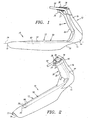
FIG. 1 is a side view of a first preferred embodiment of a retractor device in accordance with the present invention. -
FIG. 2 is a perspective view of the retractor device ofFIG. 1 , including a lightpipe shown in phantom. -
FIGS. 3A and 3B are back views of the retractor device ofFIG. 1 , with the handle cover removed and attached, respectively. -
FIG. 4 is an exploded perspective view of the retractor device ofFIG. 1 -
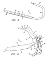
FIG. 5 is a perspective detail of a lightpipe for use with the retractor device ofFIG. 1 . -
FIG. 6 is a perspective view of an alternative embodiment of the retractor device ofFIG. 1 , including an adjustable auxiliary support member attached to a handle of the retractor device. - Turning now to the drawings,
FIGS. 1-6 show a preferred embodiment of aretractor device 10 in accordance with one aspect of the present invention. Theretractor device 10 includes anelongate member 12, ahandle 30, alightpipe 50, and ahandle cover 72. - The
elongate member 12 has aproximal end 14, adistal end 16, and an arcuate or "C" cross-section, as best seen inFIGS. 3A and 3B . The arcuate cross-section may define a portion of the periphery of a circle, an ellipse or similar shape. Thedistal end 16 is preferably rounded or streamlined to minimize tissue trauma when theretractor device 10 is directed along a dissected space in a patient (not shown), and may include adistal opening 17 to allow access beyond thedistal end 16. Theelongate member 12 defines anelongate passage 18 therein extending along alongitudinal axis 24 between the proximal and distal ends 14, 16. Theelongate member 12 also defines a longitudinal workingwindow 20 along theelongate passage 18 betweenlongitudinal edges 22 of theelongate member 12. - The
elongate member 12 may be fabricated from any suitable metal or plastic material, but preferably is formed from injection molded polymer, such as polycarbonate, or other engineering plastics. Alternatively, the elongate member may be formed in a manner which facilitates cleaning and/or of a semi-rigid material, such as polyetherimide, which may be suitable for sterilization and reuse. The material may also be substantially transparent to facilitate visualization beyond or through the walls of theelongate member 12. - The
elongate member 12 may also include circumferentially extended edges or curved tabs (not shown) integrally formed along a portion of theedges 22 of theelongate member 12 and extending peripherally from theedges 22, thereby defining an extended periphery (not shown). The extended edges may increase the size of the working space held open by theretractor device 10 since the extended periphery further tents the working space, particularly at the location adjacent the extended edges. - The
handle 30 is preferably integrally molded to and extends from theproximal end 14 of theelongate member 12, although alternatively thehandle 30 may be provided as a separate component (not shown) attachable to theelongate member 12. Thehandle 30 preferably extends substantially perpendicularly to thelongitudinal axis 24 away from theelongate passage 18, thereby facilitating manipulation of theretractor device 10 during a surgical procedure. Thehandle 30 includes afront surface 32 and side surfaces 44, preferably having a generally curved shape for facilitating grasping of thehandle 32, and includes anupper end 34. - A
cylindrical sleeve 36 is integrally molded to theupper end 34, including anaperture 38 communicating with acavity 40 within thehandle 30 defined by the front and side surfaces 32, 44. Auniversal cable adapter 37 may be attached to thecylindrical sleeve 36, for example, by insert-molding. Theuniversal cable adapter 37 may be formed from aluminum or similar material, and may include threads for securing a similarly threaded light cable or other source of light (not shown) to thecylindrical sleeve 36. Alternatively, theadapter 37 may include other connectors for cooperatively mating with a light source. - The
cavity 40 extends substantially between theupper end 34 of thehandle 30 and theproximal end 14 of theelongate member 12. A plurality ofguide rails 42 are integrally molded to thehandle 30 within thecavity 40 and extend at least partially between theaperture 38 in thecylindrical sleeve 36 and theelongate passage 18 within theelongate member 12. Thehandle 30 may also include a pair ofrecesses 46 in theupper end 34 andelongate tabs 48 along the side surfaces 44 for cooperating withtabs 78 on thehandle cover 72 to substantially secure thehandle cover 72 to thehandle 30, as described further below. - With particular reference to
FIGS. 4 and5 , thelightpipe 50 is a substantially transparent illumination member, preferably formed from injection molded plastic that allows efficient transmission of light therethrough, such as polystyrene. Thelightpipe 50 includes aproximal portion 52, a curvedintermediate portion 54 and adistal portion 56, preferably integrally molded as a single piece to prevent substantial loss of light passing therethrough. The proximal andintermediate portions proximal end 58 of thelightpipe 50. - The
distal portion 56 has a generally flat configuration defining anupper surface 60 and alower surface 62, and terminates in adistal tip 64. Preferably, theupper surface 60 includes a plurality oflateral grooves 66 extending into theupper surface 60 for deflecting light passing along thedistal portion 56 through thelower surface 62, as described further below. More preferably, thelateral grooves 66 extend substantially perpendicular to thelongitudinal axis 24 and penetrate progressively deeper into theupper surface 60 of thedistal portion 56 in the direction of thedistal tip 64 to diffuse light essentially perpendicularly to and substantially uniformly along thelongitudinal axis 24 within theelongate passage 18. The bottom of thelateral grooves 66 may be ramped at a predetermined angle, e.g., oblique with respect to thelongitudinal axis 24, to further deflect light substantially perpendicularly to thelongitudinal axis 24 towards the longitudinal workingwindow 20. - In alternative forms, the
distal portion 56 of thelightpipe 50 may be substantially cylindrical (not shown) and thelateral grooves 66 may be provided on the upper half of thedistal portion 56 and/or on the lower half of the distal portion 56 (not shown). In a further alternative, thelateral grooves 66 may be spaced progressively closer together in the direction of the distal tip 64 (not shown) to further facilitate substantially uniform diffusion of light from thedistal portion 56. - The
distal portion 56 also includes a pair of rampedtabs 68 proximate thedistal tip 64 for cooperativelyengaging slots 70 formed on aninside surface 23 of theelongate member 12 for substantially securing thedistal portion 56 of thelightpipe 50 to theelongate member 12. To attach thelightpipe 50 to theelongate member 12, theproximal portion 52 of thelightpipe 50 is directed through theaperture 38 in thehandle 30 until theintermediate portion 54 substantially engages the guide rails 42 in thecavity 40. Simultaneously, thedistal portion 56 is directed along theinside surface 23 of theelongate member 12 until the rampedtabs 68 substantially engage theslots 70. - With particular reference to
FIGS. 3B and 4 , thehandle cover 72 may then be attached to thehandle 30 to substantially enclose thecavity 40 and/or to further substantially secure thelightpipe 50 therein. Thehandle cover 72 includes aback surface 74 and side surfaces 76 having a configuration complementary to the configuration of thehandle 30. Thehandle cover 72 includestabs 78 adapted to be received in therecesses 46 in theupper end 34 of thehandle 30 such that thehandle cover 72 may be attached thereby to thehandle 30. Preferably, when thehandle cover 72 is received on thehandle 30, theelongate tabs 48 on thehandle 30 substantially engage theside walls 76 of thehandle cover 72 to further secure thehandle cover 72 onto thehandle 30. The cooperatingtabs 78 and recesses 46 and theelongate tabs 48 may substantially secure thehandle cover 72 onto thehandle 30 such that adhesives may be unnecessary. - For a reusable version of the
retractor device 10, theelongate member 12, thelightpipe 50 and thehandle cover 72 may be capable of disassembly for cleaning and/or sterilization. Alternatively, in a single use version, theelongate member 12, thelightpipe 50 and handlecover 72 may be substantially permanently attached together prior to packaging, thereby providing a ready-to-use device. For such a single use version, thehandle cover 72 may be bonded to thehandle 30 using adhesives and the like, either alone or in conjunction with cooperating tabs and recesses. - During a procedure, a light cable or other source of light (not shown) may be coupled to the
proximal portion 52 of thelightpipe 50, preferably to theuniversal cable adapter 37, such that light is directed into theproximal end 58 of thelightpipe 50. Light from the light cable then passes through the proximal andintermediate portions distal portion 56. As the light travels towards thedistal tip 64 of thedistal portion 56, the light encounters thelateral grooves 66, which deflect the light through thelower surface 62. The depth of thelateral grooves 66 into theupper surface 60 may be selectively altered to vary illumination along thedistal portion 56 of thelightpipe 50. Thus, light may be diffused in any preferred manner through thelower surface 62 along thedistal portion 56. - The
handle 30 of theretractor device 10 may be grasped in one hand, and theelongate member 12 inserted into an incision leading to a dissected space, for example, a transverse or longitudinal incision about 4 cm long, to retract subcutaneous tissue to hold open a dissected anatomic space therein. Once theelongate member 12 is positioned within the space, for example, along a vein being harvested, thelightpipe 50 transmits light into the space, and particularly to the operating area within the longitudinal workingwindow 20 of theelongate member 12. Thedistal portion 56 of thelightpipe 50 preferably diffuses the light substantially uniformly along thelongitudinal axis 24, thereby facilitating visualization of the vein and/or branches for easy ligation and removal. - In addition, as shown in
FIG. 6 , theretractor device 10 may include an auxiliary support member or stand 80 for elevating theproximal end 14 of theretractor device 10. Thesupport member 80 includes abase 82 and a pair oflegs 84 that are preferably integrally molded together. The base 82 preferably has a slightly curved shape contoured to fit the surface of a patient' s anatomy, and the pair oflegs 84 preferably extend from opposite sides of the base 82 towards one another to define a substantially triangularopen space 86, facilitating access to theelongate passage 18. - Upper ends 88 of the
legs 84 are disposed in close proximity to one another, and includetabs 90 adjacent one another that define agap 91 therebetween. Ahub 92 extends from an outer surface of eachtab 90, i.e., opposite thegap 91. Preferably, thelegs 82 are semi-rigid, i.e., are sufficiently rigid to support theretractor device 10, but are sufficiently flexible that thetabs 90 may be compressed towards one another, but resiliently return to define thenarrow gap 91. - The
handle cover 72 includes a plurality oftransverse slots 94 having a width similar to the uncompressed spacing of thetabs 90 such that thetabs 90 may be received in an individualtransverse slot 94. Thetransverse slots 94 also include a pair ofrecesses 96 therein for receiving thehubs 92. To attach thesupport member 80 to theretractor device 10, thetabs 90 are directed towards one another, i.e., reducing the width of thegap 91 between them, and then inserted into a selectedtransverse slot 94 in thehandle cover 30, the compressed profile providing clearance for thehubs 92 to enter thetransverse slot 94. Thetabs 90 may then be released, thelegs 84 resiliently returning thetabs 90 toward the uncompressed profile, apart from one another until thehubs 92 engage therecesses 96. Thus, theproximal end 14 of theretractor device 10 may be adjusted to a predetermined height above the surface of a patient's leg simply by moving thetabs 90 of thesupport member 80 to a correspondingtransverse slot 94 in thehandle cover 72. - With the
support member 80 in place at a predetermined height, theproximal end 14 of theelongate member 12 may be raised to facilitate the performance of a surgical procedure within theelongate passage 18. For example, theopen space 86 may facilitate visualization within theelongate passage 18. In addition, thesupport member 80 may facilitate the direction of surgical instruments (not shown) through theopen space 86 and into theelongate passage 18. Thesupport member 80 may also provide hands-free retraction, enabling a surgeon to use both hands during the procedure. In addition to thesupport member 80, theelongate member 12 may include recessedportions 19 adjacent theproximal end 14 to provide an enlarged entrance into theelongate passage 18, for example, to further facilitate visualization and/or the direction of surgical instruments into theelongate passage 18. - Alternatively, other adjustment mechanisms may also be provided that may, for example, be attachable or permanently fixed to the
proximal end 14. The adjustment mechanism may fix theproximal end 14 at one of a plurality of heights to tent the incision and/or to facilitate access to the working space. For example, a raised frame (not shown) may be attachable to the patient's anatomy, such as by a strap around their leg, to which theproximal end 14 may be attached. The frame should include an open space therethrough to facilitate the introduction of surgical instruments into theelongate passage 18. - An important feature of a retractor device in accordance with the present invention is the arcuate cross-section which enables the device to retract and maintain subcutaneous tissue and hold open a working space during a surgical procedure. Conventional methods may be used to incise and dissect to create a subcutaneous space initially, for example, in preparation for vein harvesting from a patient's leg. Alternatively,
U.S. Patent No. 5,601,581, issued to Fogarty et al. , discloses an apparatus and method suitable for dissecting a subcutaneous space. - To summarize such a useful procedure, a section of a tissue structure, for example a nerve or vein, especially the saphenous vein, may be selected to be harvested. An incision may be created at a location adjacent to one end of the selected structure, such as at the groin or knee. A tunneling instrument, such as a blunt or soft-tipped dissector, possibly including an inflatable balloon thereon, may be inserted into the incision and advanced along between tissue layers to identify the selected tissue structure. The tunneling instrument may be advanced along the anterior surface of the tissue structure and/or a balloon on the tunneling instrument may be inflated to create a dissected space of a desired size. Once the desired dissected space is developed, the balloon may be deflated, and the tunneling instrument may be removed from the dissected space through the incision.
- A retractor in accordance with the present invention may then be inserted into the incision and directed along the dissected space while orienting the open side of the "C" shaped cross-section, e.g., the longitudinal working
window 20, towards the tissue structure to hold open a working space above the tissue structure. Thelightpipe 50 provides illumination within the working space and, in particular, facilitates visualization of a surgical site along the tissue structure within the workingwindow 20. The arcuate shape of theretractor device 10 allows the subcutaneous tissues anterior to the surgical site, such as the tissues anterior to the saphenous vein, to be held up and away from the surgical site without needing external support. The longitudinal edges 22 of theretractor device 10 abut the subcutaneous tissues adjacent the anterior surface of the tissue structure, and the longitudinal workingwindow 20 facilitates access along a desired length of the tissue structure, for example, of a vein being harvested. Surgical instruments may be introduced into the incision and directed along the working space to any point along the length of the longitudinal workingwindow 20 without having to relocate the retractor device during a surgical procedure, such as a vein harvesting procedure. - If desired, a second incision may be created and the procedure repeated at another location on the patient's leg adjacent to the first incision, the retractor device holding open a second working space to facilitate additional tissue structure to be ligated and/or harvested. Thus, a
retractor device 10 in accordance with the present invention may allow a relatively long section of a vein, nerve or other tissue structure to be harvested through a series of relatively small incisions spaced apart from one another.
Claims (26)
- A device (10) for retraction of subcutaneous tissue to hold open a working space within a patient's body comprising:an elongate member (12) having proximal and distal ends (14, 16), and having an arcuate cross-section defining an elongate passage therein; anda substantially transparent illumination member (50) having a proximal portion (52) connectable to a source of light, and a distal portion (56) within the elongate passage for directing light from the proximal portion into the elongate passagewherein the illumination member includes in the distal portion means for diffusing light transmitted from the proximal portion into the distal portion towards a longitudinal working window (20) defined by the elongate member
characterized in that said light diffusing means is a plurality of lateral grooves (66), said lateral grooves extending progressively deeper into the distal portion towards a distal tip of the illumination member thereby diffusing light substantially uniformly along a longitudinal working window extending along the elongate passage. - The device of claim 1, further comprising a handle (30) extending from the proximal end of the elongate member.
- The device of claim 2, wherein the proximal portion of the illumination member extends through the handle.
- The device of claim 2 or 3, wherein the handle extends substantially perpendicularly to a longitudinal axis of the elongate member away from the elongate passage.
- The device of any one of the preceding claims, wherein the elongate member comprises injection molded plastic.
- The device of any one of the preceding claims, wherein the elongate member is substantially transparent.
- The device of any one of the preceding claims, wherein the illumination member comprises injection molded plastic.
- The device of any one of the preceding claims, wherein the illumination member extends along an inner surface of the elongate member.
- The device of claim 8, wherein the distal portion of the illumination member and the inner surface of the elongate member include cooperating tabs and slots (68, 70) for securing the distal portion to the inner surface.
- The device of any one of the preceding claims, further comprising a support member (80) extending from the proximal end of the elongate member for facilitating access to the elongate passage.
- The device of claim 10, wherein the support member extends substantially perpendicularly to a longitudinal axis of the elongate member toward the elongate passage.
- The device of claim 10 or 11, wherein the support member is adjustable with respect to the proximal end of the elongate member .
- The device of claim 10, 11 or 12, wherein the support member and the proximal end of the elongate member include a plurality of cooperating tabs and slots (78, 46) for detachably securing the support member to the proximal end in one of a plurality of positions with respect to one another.
- The device of claim 13, wherein the support member includes a pair of arms (84) defining an open space (86) therebetween for accessing the elongate passage through the support member.
- The device of any one of the preceding claims, further comprising an adjustment mechanism (94) on the proximal end of the elongate member for fixing the proximal end at one of a plurality of heights.
- The device of any one of the preceding claims, wherein the elongate member includes circumferentially extended edges defining an extended periphery.
- A device (10) for retraction of subcutaneous tissue to hold open a working space within a patient's body, comprising:a retractor member (10) having an elongate portion (12) including proximal and distal ends (14, 16) and having an arcuate cross-section defining an elongate passage (18) therein, and a handle (30) extending from the proximal end of the elongate portion; anda substantially transparent illumination member (50) having a proximal portion (52) connectable to a source of light, an intermediate portion (54) extending through the handle, and a distal portion (56) extending along a lower surface of the elongate portion, the distal portion including a diffusing surface for directing light from a source of light connected to the proximal portion therethrough,
characterized in that the diffusing surface is within the upper or lower surface (60, 62) of the illumination member and comprises a substantially flat surface oriented away from the lower surface of the elongate portion,
wherein the distal portion of the substantially flat surface includes a plurality of lateral grooves (66) for diffusing light along a longitudinal working window extending along the elongate passage, and
wherein the lateral grooves of the plurality are spaced progressively closer together in the direction of the distal tip to facilitate uniform diffusing of light from the distal portion. - The device of claim 17, wherein the distal portion of the illumination member extends along the elongate passage.
- The device of any one of claims 17 to 18, wherein the handle comprises a sleeve (36) through which the proximal portion of the illumination member extends.
- The device of claim 19, further comprising an adapter (37) for attaching a source of light to the sleeve.
- The device of any one of claims 17 to 20, further comprising an adjustment mechanism (94) proximate the proximal and of the elongate portion for fixing the proximal end at one of a plurality of predetermined heights.
- The device of claim 21, wherein the adjustment mechanism comprises a support member (80) that is attachable to the handle of the retractor member by a plurality of cooperating tabs and slots (90, 94).
- The device of any one of claims 17 to 22, wherein the elongate portion and the handle are integrally molded together from molded plastic.
- The device of any one of claims 17 to 23, wherein the proximal, intermediate and distal portions of the illumination member are integrally molded together from molded plastic.
- The device of any one of claims 17 to 24, wherein the handle includes a cavity (40) through which the intermediate portion of the illumination member extends.
- The device of claim 25, further comprising a handle cover (72) attachable to the handle for substantially inclosing the cavity.
Applications Claiming Priority (3)
| Application Number | Priority Date | Filing Date | Title |
|---|---|---|---|
| US09/150,909 US6196968B1 (en) | 1997-06-02 | 1998-09-10 | Direct vision subcutaneous tissue retractor and method for use |
| US150909 | 1998-09-10 | ||
| PCT/US1999/019736 WO2000015116A1 (en) | 1998-09-10 | 1999-08-30 | Direct vision subcutaneous tissue retractor |
Publications (3)
| Publication Number | Publication Date |
|---|---|
| EP1119296A1 EP1119296A1 (en) | 2001-08-01 |
| EP1119296A4 EP1119296A4 (en) | 2007-07-18 |
| EP1119296B1 true EP1119296B1 (en) | 2009-10-07 |
Family
ID=22536509
Family Applications (1)
| Application Number | Title | Priority Date | Filing Date |
|---|---|---|---|
| EP99946676A Expired - Lifetime EP1119296B1 (en) | 1998-09-10 | 1999-08-30 | Direct vision subcutaneous tissue retractor |
Country Status (7)
| Country | Link |
|---|---|
| US (1) | US6196968B1 (en) |
| EP (1) | EP1119296B1 (en) |
| JP (1) | JP4138251B2 (en) |
| CA (1) | CA2343235C (en) |
| DE (1) | DE69941514D1 (en) |
| ES (1) | ES2333921T3 (en) |
| WO (1) | WO2000015116A1 (en) |
Families Citing this family (81)
| Publication number | Priority date | Publication date | Assignee | Title |
|---|---|---|---|---|
| US6200263B1 (en) | 1998-01-23 | 2001-03-13 | United States Surgical Corporation | Surgical instrument holder |
| DE19827360C2 (en) * | 1998-06-19 | 2000-05-31 | Storz Karl Gmbh & Co Kg | Medical instrument for endoscopic removal of the saphenous vein |
| US6648815B2 (en) | 1998-06-19 | 2003-11-18 | Karl Storz Gmbh & Co. Kg | Medical instrument and method for endoscopic removal of the saphenous vein |
| EP0979635A2 (en) | 1998-08-12 | 2000-02-16 | Origin Medsystems, Inc. | Tissue dissector apparatus |
| US6322499B1 (en) * | 2000-01-20 | 2001-11-27 | Genzyme Corporation | Pivotal and illuminated saphenous vein retractor |
| US6558313B1 (en) | 2000-11-17 | 2003-05-06 | Embro Corporation | Vein harvesting system and method |
| US6620161B2 (en) | 2001-01-24 | 2003-09-16 | Ethicon, Inc. | Electrosurgical instrument with an operational sequencing element |
| US6554829B2 (en) | 2001-01-24 | 2003-04-29 | Ethicon, Inc. | Electrosurgical instrument with minimally invasive jaws |
| US6464702B2 (en) | 2001-01-24 | 2002-10-15 | Ethicon, Inc. | Electrosurgical instrument with closing tube for conducting RF energy and moving jaws |
| US6458128B1 (en) | 2001-01-24 | 2002-10-01 | Ethicon, Inc. | Electrosurgical instrument with a longitudinal element for conducting RF energy and moving a cutting element |
| US6652521B2 (en) | 2001-01-24 | 2003-11-25 | Ethicon, Inc. | Surgical instrument with a bi-directional cutting element |
| US6443970B1 (en) | 2001-01-24 | 2002-09-03 | Ethicon, Inc. | Surgical instrument with a dissecting tip |
| CA2455385C (en) | 2001-06-26 | 2011-01-25 | Tyco Healthcare Group, Lp | Conduit harvesting instrument and method |
| DE60238484D1 (en) * | 2001-06-27 | 2011-01-13 | Depuy Products Inc | Minimally invasive orthopedic device |
| US7137949B2 (en) * | 2001-07-13 | 2006-11-21 | United States Surgical Corporation | Surgical instrument |
| AU2002355439B2 (en) | 2001-08-10 | 2007-11-15 | Covidien Lp | Retractor for vasculary surgery, and methods of use |
| WO2003013367A2 (en) | 2001-08-10 | 2003-02-20 | General Surgical Innovations Inc. | Vascular harvesting tool and methods |
| US6572615B2 (en) | 2001-09-28 | 2003-06-03 | Ethicon, Inc. | Surgical device for applying radio frequency energy to a portion of a captured vessel |
| US6592582B2 (en) | 2001-09-28 | 2003-07-15 | Ethicon, Inc. | Vessel harvesting retractor with electrosurgical plunger |
| US6592604B2 (en) | 2001-09-28 | 2003-07-15 | Ethicon, Inc. | Vessel harvesting retractor with dissection element |
| US6656176B2 (en) | 2001-09-28 | 2003-12-02 | Ethicon, Inc. | Vessel harvesting retractor with integral electrosurgical clamping elements |
| US6817978B2 (en) | 2002-01-23 | 2004-11-16 | Teleflex-Ct Devices Incorporated | Illuminated retractor for use in connection with harvesting a blood vessel from the arm |
| US6551314B1 (en) | 2002-04-03 | 2003-04-22 | Thomas J. Fogarty | Methods and systems for vein harvesting |
| US7074220B2 (en) * | 2002-04-03 | 2006-07-11 | Thomas J. Fogarty | Methods and systems for vein harvesting and fistula creation |
| US20040049208A1 (en) * | 2002-04-03 | 2004-03-11 | Thomas Fogarty, M.D. | Methods and systems for vein harvesting and fistula creation |
| US6805666B2 (en) | 2002-05-23 | 2004-10-19 | Donna D. Holland | Pivotal and illuminated saphenous vein retractor with tapered design |
| EP1545370B1 (en) * | 2002-08-02 | 2008-12-10 | Warsaw Orthopedic, Inc. | Systems and techniques for illuminating a surgical space |
| US7223233B2 (en) * | 2002-08-02 | 2007-05-29 | Warsaw Orthopedic, Inc. | Systems and techniques for illuminating a surgical space |
| US7371213B2 (en) * | 2003-01-31 | 2008-05-13 | Zimmer Technology, Inc. | Lit retractor |
| US7503894B2 (en) * | 2003-01-31 | 2009-03-17 | Zimmer Technology, Inc. | Lit retractor |
| US20050182301A1 (en) * | 2003-01-31 | 2005-08-18 | Zimmer Technology, Inc. | Lit retractor |
| WO2004077922A2 (en) * | 2003-03-07 | 2004-09-16 | Howmedica Osteonics Corporation | Illuminable retractor |
| US20040236231A1 (en) * | 2003-05-23 | 2004-11-25 | Embro Corporation | Light catheter for illuminating tissue structures |
| US7232462B2 (en) * | 2004-03-31 | 2007-06-19 | Cook Incorporated | Self centering delivery catheter |
| EP2263556A1 (en) * | 2004-05-13 | 2010-12-22 | Medtronic, Inc. | Percutaneous vein harvester |
| US7846171B2 (en) | 2004-05-27 | 2010-12-07 | C.R. Bard, Inc. | Method and apparatus for delivering a prosthetic fabric into a patient |
| US8480696B2 (en) * | 2004-06-16 | 2013-07-09 | Medtronic, Inc. | Minimally invasive coring vein harvester |
| US20060036274A1 (en) * | 2004-06-25 | 2006-02-16 | Usher Raymond W | One-piece vessel harvester |
| US7762951B2 (en) * | 2004-06-25 | 2010-07-27 | Medtronic, Inc. | Vein harvesting system including dilator shaft and removable retractor housing |
| US20060189849A1 (en) * | 2005-02-22 | 2006-08-24 | Sharratt Todd W | Surgical illumination device and method of using |
| US7951077B2 (en) * | 2005-07-15 | 2011-05-31 | Sayeg Ayoub Dr | Method and instruments for breast augmentation mammaplasty |
| US20070118119A1 (en) * | 2005-11-18 | 2007-05-24 | Zimmer Spine, Inc. | Methods and device for dynamic stabilization |
| US8409088B2 (en) | 2006-01-18 | 2013-04-02 | Invuity, Inc. | Retractor illumination system |
| US20070244371A1 (en) * | 2006-04-04 | 2007-10-18 | Nguyen Hoa D | Phlebectomy illumination device and methods |
| US8430813B2 (en) * | 2006-05-26 | 2013-04-30 | Depuy Spine, Inc. | Illuminated surgical access system including a surgical access device and integrated light emitter |
| US8047987B2 (en) * | 2006-05-26 | 2011-11-01 | Invuity, Inc. | Blade insert illuminator |
| US9770230B2 (en) | 2006-06-01 | 2017-09-26 | Maquet Cardiovascular Llc | Endoscopic vessel harvesting system components |
| US20080033251A1 (en) * | 2006-06-30 | 2008-02-07 | Ali Araghi | Surgical retractor and method of use |
| EP2099386A4 (en) * | 2006-10-16 | 2012-11-14 | Scottsdale Medical Devices Inc | Cutting device and method of vessel harvesting |
| US8029544B2 (en) * | 2007-01-02 | 2011-10-04 | Zimmer Spine, Inc. | Spine stiffening device |
| US8062217B2 (en) * | 2007-01-26 | 2011-11-22 | Theken Spine, Llc | Surgical retractor with removable blades and method of use |
| US20080183044A1 (en) * | 2007-01-26 | 2008-07-31 | Dennis Colleran | Flexible surgical retractor and method of use |
| FR2915098B1 (en) | 2007-04-19 | 2009-06-05 | Sanofi Aventis Sa | USE OF 4-CYCLOPROPYLMETHOXY-N- (3,5-DICHLORO-1-OXYDO-PYRIDIN-4-YL) -5- (METHOXY) PYRIDINE-2-CARBOXAMIDE FOR THE TREATMENT OF TRAUMATISMS OF SPINAL CORD |
| US20080287937A1 (en) * | 2007-05-15 | 2008-11-20 | Warsaw Orthopedic, Inc. | Surgical Instrument for Illuminating and Monitoring a Surgical Site |
| US8088066B2 (en) | 2007-10-24 | 2012-01-03 | Invuity, Inc. | Blade insert illuminator |
| WO2009082656A1 (en) * | 2007-12-21 | 2009-07-02 | Smith & Nephew, Inc. | Cannula |
| GB0800835D0 (en) | 2008-01-17 | 2008-02-27 | Cardioprec Ltd | Retractor |
| CN101336822B (en) * | 2008-05-21 | 2010-06-16 | 王鹏 | Dilator and constituted one-pore double-viewpoint electric cavity mirror system |
| US11382711B2 (en) | 2008-08-13 | 2022-07-12 | Invuity, Inc. | Cyclo olefin polymer and copolymer medical devices |
| US20100280328A1 (en) * | 2009-05-01 | 2010-11-04 | Tyco Healthcare Group, Lp | Methods and systems for illumination during phlebectomy procedures |
| US20100305406A1 (en) * | 2009-05-26 | 2010-12-02 | Ori Braun | System, device and method for gynecological use |
| US9339264B2 (en) * | 2010-10-01 | 2016-05-17 | Cook Medical Technologies Llc | Port access visualization platform |
| US8435245B2 (en) * | 2009-12-17 | 2013-05-07 | Custom Spine, Inc. | Surgical implant insertion apparatus and method |
| US8414484B2 (en) | 2009-12-17 | 2013-04-09 | Custom Spine, Inc. | Percutaneous tube assembly |
| US20110172688A1 (en) * | 2010-01-11 | 2011-07-14 | Tyco Healthcare Group Lp | Conduit Harvesting Instrument and Method |
| JP5595522B2 (en) * | 2010-01-14 | 2014-09-24 | サージカル イノベーション ヘルスケア カンパニー リミテッド | Surgical system |
| GB201015746D0 (en) | 2010-09-21 | 2010-10-27 | Cardioprec Ltd | Optical switch |
| JP6379178B2 (en) | 2013-04-01 | 2018-08-22 | ビノド ヴイ パシー | Lighting device |
| USD938095S1 (en) | 2013-04-01 | 2021-12-07 | Pathy Medical, Llc | Lighting device |
| WO2015116724A1 (en) | 2014-01-28 | 2015-08-06 | Invuity, Inc. | Drop in surgical illuminator |
| EP3679864B1 (en) | 2014-09-13 | 2022-11-09 | Yusuke Shimizu | Medical retractor |
| US10575835B2 (en) | 2014-10-14 | 2020-03-03 | Covidien Lp | Methods and devices for vein harvesting |
| US10646210B2 (en) | 2014-10-14 | 2020-05-12 | Covidien Lp | Methods and devices for vein harvesting |
| US10433960B1 (en) | 2015-05-07 | 2019-10-08 | Cardioprecision Limited | Method and system for transcatheter intervention |
| US10064611B2 (en) | 2015-07-22 | 2018-09-04 | Covidien Lp | Methods and devices for vein harvesting |
| WO2018140208A1 (en) | 2017-01-24 | 2018-08-02 | Medtronic Advanced Energy Llc | Modular lighted surgical retractor |
| USD846119S1 (en) | 2017-01-24 | 2019-04-16 | Medtronic Advanced Energy Llc | Lighted surgical retractor base |
| EP3375379A1 (en) * | 2017-03-17 | 2018-09-19 | The Prince Of Songkla University | Surgical visual field enhancer and surgical knife |
| US11547466B2 (en) | 2018-06-20 | 2023-01-10 | Covidien Lp | Visualization devices and methods for use in surgical procedures |
| US11197687B2 (en) | 2018-08-01 | 2021-12-14 | Medtronic, Inc. | Medical tools for and methods of gaining access to extra vascular spaces |
| AU2021289686A1 (en) * | 2020-06-09 | 2022-12-15 | Smith & Nephew Asia Pacific Pte Limited | System and method for harvesting a tendon |
Family Cites Families (28)
| Publication number | Priority date | Publication date | Assignee | Title |
|---|---|---|---|---|
| US518842A (en) | 1894-04-24 | Mowing-machine attachment | ||
| US659182A (en) | 1900-05-21 | 1900-10-02 | George P Pilling | Retractor. |
| GB375491A (en) * | 1931-05-09 | 1932-06-30 | Robert Schranz | Improvements in laryngoscopes and the like |
| US2082782A (en) | 1935-10-03 | 1937-06-08 | Alfred G Allen | Vacuum tenaculum |
| US2201331A (en) | 1938-11-03 | 1940-05-21 | Alfred G Wright | Mouth prop and light carrier |
| US2575253A (en) | 1949-05-16 | 1951-11-13 | Joseph F Bicek | Vaginal speculum |
| US2653597A (en) | 1949-12-09 | 1953-09-29 | Walter T Canan | Tongue depressor and mirror therefor |
| US2812758A (en) | 1955-07-26 | 1957-11-12 | John C Blumenschein | Surgical retractor |
| US2829649A (en) | 1956-01-17 | 1958-04-08 | Robert J Glenner | Hemostat-retractor |
| US3509873A (en) | 1967-04-24 | 1970-05-05 | Jack B Karlin | Retractor |
| US3570475A (en) | 1968-11-14 | 1971-03-16 | Mandel Weinstein | Surgical retractor |
| US3638644A (en) * | 1969-03-05 | 1972-02-01 | Michael Elbert | Illuminated surgical speculum |
| US3651800A (en) | 1970-05-15 | 1972-03-28 | James L Wilbanks | Surgical instrument |
| US3851642A (en) * | 1971-10-26 | 1974-12-03 | Medical Testing Syst Inc | Medical examining instrument |
| US4232660A (en) | 1979-03-26 | 1980-11-11 | Coles Robert L | Winged irrigating surgical retractor |
| DE3023266A1 (en) * | 1980-06-21 | 1982-01-07 | Original Hanau Heraeus Gmbh, 6450 Hanau | WOUND HOOK FOR SURGICAL PURPOSES |
| US4380999A (en) | 1980-07-15 | 1983-04-26 | Healy Keelin E | Stepped surgical retractor |
| US4934352A (en) | 1982-10-22 | 1990-06-19 | Sullivan Jr Eugene M | Surgical retractor handle construction |
| DE3301890C2 (en) * | 1983-01-21 | 1986-04-10 | W.C. Heraeus Gmbh, 6450 Hanau | Retractor |
| US4562832A (en) | 1984-01-21 | 1986-01-07 | Wilder Joseph R | Medical instrument and light pipe illumination assembly |
| US4686972A (en) | 1986-04-30 | 1987-08-18 | Kurland Kenneth Z | Surgical deflector and drilling guide |
| FR2662929A1 (en) | 1990-06-08 | 1991-12-13 | Berlinski Michel | Surgical instrument of the retractor or vaginal retractor type |
| US5128842A (en) * | 1991-06-03 | 1992-07-07 | Sunarrow Co., Inc. | Uniform illumination plate |
| US5667480A (en) | 1995-10-20 | 1997-09-16 | Ethicon Endo-Surgery, Inc. | Method and devices for endoscopic vessel harvesting |
| US5913818A (en) * | 1997-06-02 | 1999-06-22 | General Surgical Innovations, Inc. | Vascular retractor |
| US6033361A (en) * | 1997-06-02 | 2000-03-07 | General Surgical Innovations, Inc. | Vascular retractor |
| US5902315A (en) * | 1997-08-28 | 1999-05-11 | Ethicon Endo-Surgery, Inc. | Optical tissue dissector/retractor |
| US5922004A (en) * | 1997-08-28 | 1999-07-13 | Ethicon Endo-Surgery, Inc. | Method for performing optical tissue dissection/retraction |
-
1998
- 1998-09-10 US US09/150,909 patent/US6196968B1/en not_active Expired - Lifetime
-
1999
- 1999-08-30 CA CA002343235A patent/CA2343235C/en not_active Expired - Fee Related
- 1999-08-30 DE DE69941514T patent/DE69941514D1/en not_active Expired - Lifetime
- 1999-08-30 JP JP2000569703A patent/JP4138251B2/en not_active Expired - Fee Related
- 1999-08-30 EP EP99946676A patent/EP1119296B1/en not_active Expired - Lifetime
- 1999-08-30 ES ES99946676T patent/ES2333921T3/en not_active Expired - Lifetime
- 1999-08-30 WO PCT/US1999/019736 patent/WO2000015116A1/en active Application Filing
Also Published As
| Publication number | Publication date |
|---|---|
| CA2343235A1 (en) | 2000-03-23 |
| DE69941514D1 (en) | 2009-11-19 |
| EP1119296A4 (en) | 2007-07-18 |
| WO2000015116A9 (en) | 2000-06-22 |
| WO2000015116A1 (en) | 2000-03-23 |
| EP1119296A1 (en) | 2001-08-01 |
| ES2333921T3 (en) | 2010-03-02 |
| CA2343235C (en) | 2007-05-22 |
| US6196968B1 (en) | 2001-03-06 |
| JP2002524182A (en) | 2002-08-06 |
| JP4138251B2 (en) | 2008-08-27 |
Similar Documents
| Publication | Publication Date | Title |
|---|---|---|
| EP1119296B1 (en) | Direct vision subcutaneous tissue retractor | |
| US6482153B1 (en) | Illuminated surgical retractor | |
| US5928138A (en) | Method and devices for endoscopic vessel harvesting | |
| US5667480A (en) | Method and devices for endoscopic vessel harvesting | |
| US5938680A (en) | Devices and methods for harvesting vascular conduits | |
| EP1690498B1 (en) | Retractor for endoscopic surgery | |
| CA2396903C (en) | Pivotal and illuminated saphenous vein retractor | |
| US6817978B2 (en) | Illuminated retractor for use in connection with harvesting a blood vessel from the arm | |
| AU2002355439B2 (en) | Retractor for vasculary surgery, and methods of use | |
| AU2002355439A1 (en) | Retractor for vasculary surgery, and methods of use | |
| AU776480B2 (en) | Illuminated surgical retractor | |
| CA2537342C (en) | Method and devices for endoscopic vessel harvesting |
Legal Events
| Date | Code | Title | Description |
|---|---|---|---|
| PUAI | Public reference made under article 153(3) epc to a published international application that has entered the european phase |
Free format text: ORIGINAL CODE: 0009012 |
|
| 17P | Request for examination filed |
Effective date: 20010406 |
|
| AK | Designated contracting states |
Kind code of ref document: A1 Designated state(s): AT BE CH CY DE DK ES FI FR GB GR IE IT LI LU MC NL PT SE |
|
| RBV | Designated contracting states (corrected) |
Designated state(s): DE ES FR GB IE IT |
|
| A4 | Supplementary search report drawn up and despatched |
Effective date: 20070620 |
|
| 17Q | First examination report despatched |
Effective date: 20070920 |
|
| GRAP | Despatch of communication of intention to grant a patent |
Free format text: ORIGINAL CODE: EPIDOSNIGR1 |
|
| RTI1 | Title (correction) |
Free format text: DIRECT VISION SUBCUTANEOUS TISSUE RETRACTOR |
|
| GRAS | Grant fee paid |
Free format text: ORIGINAL CODE: EPIDOSNIGR3 |
|
| GRAA | (expected) grant |
Free format text: ORIGINAL CODE: 0009210 |
|
| AK | Designated contracting states |
Kind code of ref document: B1 Designated state(s): DE ES FR GB IE IT |
|
| REG | Reference to a national code |
Ref country code: GB Ref legal event code: FG4D |
|
| REG | Reference to a national code |
Ref country code: IE Ref legal event code: FG4D |
|
| REF | Corresponds to: |
Ref document number: 69941514 Country of ref document: DE Date of ref document: 20091119 Kind code of ref document: P |
|
| REG | Reference to a national code |
Ref country code: ES Ref legal event code: FG2A Ref document number: 2333921 Country of ref document: ES Kind code of ref document: T3 |
|
| PLBE | No opposition filed within time limit |
Free format text: ORIGINAL CODE: 0009261 |
|
| STAA | Information on the status of an ep patent application or granted ep patent |
Free format text: STATUS: NO OPPOSITION FILED WITHIN TIME LIMIT |
|
| 26N | No opposition filed |
Effective date: 20100708 |
|
| PGFP | Annual fee paid to national office [announced via postgrant information from national office to epo] |
Ref country code: ES Payment date: 20110826 Year of fee payment: 13 |
|
| PGFP | Annual fee paid to national office [announced via postgrant information from national office to epo] |
Ref country code: IT Payment date: 20110824 Year of fee payment: 13 |
|
| PG25 | Lapsed in a contracting state [announced via postgrant information from national office to epo] |
Ref country code: IT Free format text: LAPSE BECAUSE OF NON-PAYMENT OF DUE FEES Effective date: 20120830 |
|
| REG | Reference to a national code |
Ref country code: ES Ref legal event code: FD2A Effective date: 20131021 |
|
| PG25 | Lapsed in a contracting state [announced via postgrant information from national office to epo] |
Ref country code: ES Free format text: LAPSE BECAUSE OF NON-PAYMENT OF DUE FEES Effective date: 20120831 |
|
| REG | Reference to a national code |
Ref country code: FR Ref legal event code: PLFP Year of fee payment: 18 |
|
| PGFP | Annual fee paid to national office [announced via postgrant information from national office to epo] |
Ref country code: IE Payment date: 20160721 Year of fee payment: 18 Ref country code: DE Payment date: 20160721 Year of fee payment: 18 Ref country code: GB Payment date: 20160726 Year of fee payment: 18 |
|
| PGFP | Annual fee paid to national office [announced via postgrant information from national office to epo] |
Ref country code: FR Payment date: 20160720 Year of fee payment: 18 |
|
| REG | Reference to a national code |
Ref country code: DE Ref legal event code: R119 Ref document number: 69941514 Country of ref document: DE |
|
| GBPC | Gb: european patent ceased through non-payment of renewal fee |
Effective date: 20170830 |
|
| REG | Reference to a national code |
Ref country code: FR Ref legal event code: ST Effective date: 20180430 |
|
| REG | Reference to a national code |
Ref country code: IE Ref legal event code: MM4A |
|
| PG25 | Lapsed in a contracting state [announced via postgrant information from national office to epo] |
Ref country code: DE Free format text: LAPSE BECAUSE OF NON-PAYMENT OF DUE FEES Effective date: 20180301 Ref country code: IE Free format text: LAPSE BECAUSE OF NON-PAYMENT OF DUE FEES Effective date: 20170830 Ref country code: GB Free format text: LAPSE BECAUSE OF NON-PAYMENT OF DUE FEES Effective date: 20170830 |
|
| PG25 | Lapsed in a contracting state [announced via postgrant information from national office to epo] |
Ref country code: FR Free format text: LAPSE BECAUSE OF NON-PAYMENT OF DUE FEES Effective date: 20170831 |