EP1120983A1 - Apparatus and method for measuring and controlling the performance of an adjustable antenna on a sub-sector basis - Google Patents
Apparatus and method for measuring and controlling the performance of an adjustable antenna on a sub-sector basis Download PDFInfo
- Publication number
- EP1120983A1 EP1120983A1 EP00306697A EP00306697A EP1120983A1 EP 1120983 A1 EP1120983 A1 EP 1120983A1 EP 00306697 A EP00306697 A EP 00306697A EP 00306697 A EP00306697 A EP 00306697A EP 1120983 A1 EP1120983 A1 EP 1120983A1
- Authority
- EP
- European Patent Office
- Prior art keywords
- sector
- sub
- base station
- wireless communications
- communications system
- Prior art date
- Legal status (The legal status is an assumption and is not a legal conclusion. Google has not performed a legal analysis and makes no representation as to the accuracy of the status listed.)
- Granted
Links
Images


Classifications
-
- H—ELECTRICITY
- H04—ELECTRIC COMMUNICATION TECHNIQUE
- H04W—WIRELESS COMMUNICATION NETWORKS
- H04W24/00—Supervisory, monitoring or testing arrangements
-
- H—ELECTRICITY
- H04—ELECTRIC COMMUNICATION TECHNIQUE
- H04W—WIRELESS COMMUNICATION NETWORKS
- H04W16/00—Network planning, e.g. coverage or traffic planning tools; Network deployment, e.g. resource partitioning or cells structures
- H04W16/24—Cell structures
Landscapes
- Engineering & Computer Science (AREA)
- Computer Networks & Wireless Communication (AREA)
- Signal Processing (AREA)
- Mobile Radio Communication Systems (AREA)
- Radio Transmission System (AREA)
- Variable-Direction Aerials And Aerial Arrays (AREA)
- Monitoring And Testing Of Transmission In General (AREA)
Abstract
Description
- This invention relates to a wireless communications system that monitors and adjusts a base station antenna's signal broadcast radiation pattern in order to improve its performance.
- A wireless communications system is engineered to serve a desired level of traffic according to radio transmission characteristics that are assumed to provide homogeneous signal strength coverage over a defined geographic area and are assumed to be time invariant. However, radio conditions between mobile subscriber units and serving base stations change with time, which degrades the performance of the wireless communications system (possibly substantially). Degradation of the wireless communications system's performance can be manifested in a number of ways. Examples include an increased dropped call rate and an increased frame error rate. The wireless communications system may require periodic "retuning" of base station antennas in order to maintain the engineered performance objectives. Each retuning of a base station may require that a technician physically travel to a base station's location. The effort associated with retuning is amplified by the number of base stations (which may be in the hundreds) associated with the wireless communications system. Thus, the task of retuning the wireless communications system is labor-intensive, time-consuming and expensive.
- Additionally, radio characteristics are usually not homogeneous within a serving area of a base station antenna. Within the serving area, factors such as buildings, foliage, terrain and weather are not homogeneous, causing radio characteristics not to be homogeneous. Moreover, these factors may change with time, e.g. new buildings are constructed within the service area and the leaves of trees grow and fall with the seasons of the year. These phenomena cause "holes" in the radio coverage area. Increasing the signal strength in the direction of the hole can compensate for the deficiency.
- With the prior art, "drive tests" are periodically conducted in order to detect holes in radio frequency (RF) coverage. Drive tests require that technicians operate mobile subscriber units while traversing routes and collecting measurements within the coverage area of the wireless communications system. The measurements are typically stored on a recording medium attached to the mobile subscriber unit. The measurements are subsequently analyzed to evaluate the RF coverage as provided by the wireless communications system.
- A base station serves a region called a cell, which is further partitioned into sectors. The base station serves multiple sectors of a cell with each sector corresponding to a base station antenna. Because RF characteristics may not be homogeneous within a sub-region (sub-sector) of a sector, each base station antenna (sector) may require adjustments that are dependent upon a subregion of the given sector. Periodic retuning (that is typical with the prior art) must therefore account for the heterogeneous nature of RF characteristics. Thus, the wireless industry has a definite and urgent need for an invention that allows a wireless service provider to automatically retune the base station antennas within the wireless communications system in order to provide better service at a lower cost.
- The present invention enables a service provider of a wireless communications system to measure and retune the radiation patterns of base station antennas without labor-intensive effort that is typical with the prior art. The present invention includes both apparatus and methods in which measurements are collected and in which performance metrics are derived from the measurements and analyzed so that an adjustable base station antenna can be controlled. Examples of adjustable base station antennas include linear array antennas and narrow beam antenna configurations as disclosed in the exemplary embodiment. The performance metrics are derived from measurements that are associated with subregions (sub-sectors) within the sector of the serving base station antenna. In order to accomplish this association, an approximate location of a mobile subscriber unit is determined at the time of a measurement. Control signals that are applied to adjustable base station antennas are calculated so that the performance metrics of the sub-sector are improved within the constraints limiting the degradation of performance metrics of other subsectors.
- Numerous other advantages and features of the present invention will become readily apparent from the detailed description of the invention and the embodiments thereof, from the claims, and from the accompanying drawings.
-
- FIG. 1 illustrates an architecture of a wireless communications system;
- FIG. 2 illustrates partitioning the coverage of two essentially abutting cells with each cell served by a base station as shown in FIG. 1;
- FIG. 3 shows further partitioning of a cell's sector into sub-sectors in which the sector is served through the base station antenna shown in FIG. 1;
- FIG. 4 illustrates a coverage of a base station antenna configured with a narrow beam signal broadcast radiation pattern for each sub-sector;
- FIG. 5 illustrates apparatus controlling an adjustable base station antenna serving a sector of a cell;
- FIG. 6 shows a flow diagram operative in the apparatus of FIG. 5 for collecting measurements that are associated with each sub-sector;
- FIG. 7 shows a flow diagram for analyzing measurements for each sub-sector and for controlling an adjustable base station antenna of a sector; and
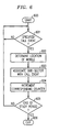
- FIG. 8 shows a flow diagram for analyzing measurements for each sub-sector and for incrementally controlling and adjusting an adjustable base station antenna associated with a sector.
-
- FIG. 1 illustrates the architecture of a
wireless communications system 10 servingmobile subscriber units base stations base station antennas radio channels Base stations Base stations processor 114, andantenna controller 115. PSTN 113 allows MSC 112 to establish incoming and outgoing calls withmobile subscriber units processor 114, in response to commands from MSC 112, provides information about the location ofmobile subscriber units - Locating
processor 114 andantenna controller 115 may be physically separated fromMSC 112, physically situated withinMSC 112, or physically distributed throughoutwireless communications system 10. In the exemplary embodiment of the present invention, locatingprocessor 114 andantenna controller 115 are both distributed withinwireless communications system 10. In the exemplary embodiment,location processor 114 is the same as or similar to the one described in U.S. Patent No. 5,963,866, issued to Palamara, et al., and assigned to Lucent Technologies, Inc.Location processor 114 determines the location of a mobile subscriber unit by transmitting an audit signal, receiving a confirmation signal, time stamping the confirmation signal, and processing information from time stamping. The present invention allows for other approaches in order to locate a mobile subscriber unit. One alternative is for MSC 112 to request a position determining entity (PDE) for location information of a mobile subscriber unit (such asmobile subscriber unit Phase 2.) -
Antenna controller 115 causes the adjustment ofbase station antennas control signals Control signals attenuators phase shifters attenuators phase shifters attenuators phase shifters - FIG. 2 illustrates two essentially abutting
cells base stations cell 200 is partitioned intosectors cell 201 is partitioned intosectors base station antennas - FIG. 3 shows further partitioning
sector 203 intosub-sectors base station antenna sector 203 is a linear array antenna. A linear array antenna comprises at least one antenna element. For each antenna element, the control signals are adjusted both in amplitude and in phase. Linear array antennas are known to one skilled in the art and are discussed in detail by a number of references. (Hansen, R.C., Phased Array Antennas, John Wiley and Sons, Inc., 1998, pp. 47-105; Rudge, A.W., et al., The Handbook of Antenna Design, Peter Peregrinus Ltd., 1986, pp. 695-834.) - FIG. 4 shows a second antenna configuration of the present invention. The base station antenna associated with
sector 203 is an array of antenna elements, each antenna element providing coverage for a sub-sector and each antenna element having a narrow beam radiation pattern. Narrowbeam radiation patterns sub-sectors Antenna controller 115 individually adjusts each narrowbeam radiation pattern - FIG. 5 shows the apparatus comprising
antenna controller 115, which is applicable to both the first and the second antenna configurations of the present invention. A base station antenna, which is associated with a sector, comprisesantenna elements Antenna elements coaxial cables Duplexers antenna elements - The transmitted signal to
antenna element 501 is coupled totransmitter 513 throughphase shifter 517,attenuator 516, andamplifier 510; the transmitted signal toantenna element 502 is coupled totransmitter 513 throughphase shifter 519,attenuator 518, andamplifier 511. The signal transmitted toantenna element 503 is coupled totransmitter 513 throughphase shifter 521,attenuator 520, andamplifier 512. - The signal received from
antenna element 501 is coupled toreceiver 515 throughphase shifter 523,attenuator 522, andcombiner 514; the received signal fromantenna element 502 is coupled toreceiver 515 throughphase shifter 525,attenuator 524, andcombiner 514; and the received signal fromantenna element 503 is coupled toreceiver 515 throughphase shifter 527,attenuator 526, andcombiner 514.Combiner 514 sums the received signals fromantenna elements -
Phase shifters attenuators antenna controller 115. The value of a control signal that is applied to each phase shifter and attenuator is determined byantenna controller 115 and coupled to the associated device. Thus, in FIG. 1, antenna controller determines the values M.sub.1, P.sub.1, M.sub.2, P.sub.2 , M.sub.N, and P.sub.N, corresponding to controlsignals attenuators phase shifters attenuators phase shifters attenuators shifter - With the second antenna configuration, each antenna element has a narrow beam radiation pattern, corresponding to a specific angular region of the associated sector (i.e. sub-sector). Consequently,
phase shifters phase shifters - In the exemplary embodiment of the present invention, the control signal values of a given antenna element associated with the transmit path are the same as with the receive path. However, since the frequency of the transmitted signal is usually different from the frequency of the received signal, the radio characteristics of the receive path and the transmit path are different. If the differences are substantial, it may be necessary that the control signal values associated with the transmit path and the receive path be different. The present invention supports such cases.
- With a uniform spaced linear antenna array for isotropic antenna elements (in which the radiation pattern is uniform in all directions), the radiation pattern is determined by
-
Equation 1 can be extended to cases in which the antenna elements are not isotropic (as characterized by any directional antenna such as a dipole antenna) by multiplying the radiation pattern determined inEquation 1 by the radiation pattern of a directional antenna element, assuming that all antenna elements of the linear array antenna are the same. This assumption simplifies the solution toEquation 1 because spatial periodicity is introduced. Because the magnitude and not the phase of the received signal is important, only the absolute value of F(theta) inEquation 1 needs to be determined. Both the variables N and d are known from a given antenna array. The absolute values of F(theta) are precalculated for different values of A.sub.i from which a lookup table is formed. If measurements indicate that signal strength in a given direction, i.e. absolute value of F(theta) needs to modified, values of A.sub.i can be retrieved from the lookup table that corresponds to the change in F(theta). However, one skilled in the art appreciates the fact that basic principles of electromagnetics must be observed. For example, if the total radiated power (integrated over all values of theta) is constant, then if the absolute value of F(theta) is increased in one direction, then the absolute value of F(theta) must be decreased in some other directions. - In the exemplary embodiment disclosed herein, the control signal values of each antenna element apply to all calls being served by a given sector ar a given time. (Even though FIG. 1 shows one mobile subscriber unit being served by a base station, e.g.
mobile subscriber unit 100 served bybase station 103, a plurality of mobile subscriber units are typically served by a given sector.) In other words, control signal values are not determined for each specific call as may be the case for "smart antennas." The present invention utilizes measurements from all calls on a given sector over a study period and determines the resulting updated control signal values for the given sector. These updated control signal values are used until the control values are recalculated during a subsequent study period. With the present invention, measurements include accumulated peg counts determined by call processing (service measurements and call processing failures). - Service measurements are typically counts associated with normal call processing including frame error rates on the forward radio channel (downlink) and the reverse radio channel (uplink), calls blocked on either the forward or reverse radio channel, and handoff failures. Call processing failures are additional counts that are generated for specific calls that cannot be sustained such as a dropped call. Measurements generated by either source are accumulated over the study period (e.g. one-hour).
- FIG. 6 illustrates a call flow in which measurements are accumulated and grouped with respect to sub-sector for each of the disclosed exemplary embodiment. Step 600 activates the process at the beginning of the study period. In
step 601 if a specific call event (e.g. a dropped call, blocked call, excessive forward frame error rate, or excessive reverse frame error rate) is detected,MSC 112 requests that locatingprocessor 114 determine the location ofmobile subscriber unit step 602. If locatingprocessor 114 cannot determine the location of the mobile subscriber unit,MSC 112 uses a last determined location of themobile subscriber unit MSC 112 uses the location information obtained instep 602 to associate and accumulate the measurement obtained instep 601 with a specific sub-sector. The corresponding counter is incremented instep 604. This process is continued over the entire study period for all call events. Step 605 determines if the study period is complete. If not, step 601 is repeated; otherwise, step 606 exits the routine (i.e. the study period has ended). The routine in FIG. 6 provides a collection of counters representing performance metrics associated with each of the sub-sectors. - FIG. 7 shows a flow diagram (which may be used by either of the antenna configurations) for analyzing the measurements that are collected by the process shown in FIG. 6. The process starts in
step 700. Instep 701, it is determined if a first performance metric of a specific sub-sector, as calculated from the counters from the process of FIG. 6, requires an improvement. As an example, dropped calls can be collected for each sub-sector in the process of FIG. 6. These measurements can be normalized by the number of calls associated with the given sub-sector to provide a dropped call rate performance metric. If the dropped call rate performance metric is above a threshold (i.e. there are too many dropped calls), as predetermined by the service provider,step 701 indicates that the first performance metric associated with the given sub-sector requires an improvement. Instep 702, updated control values associated with the sub-sectors of the associated sector are determined (e.g. the dropped call rate needs to be reduced). Step 702 must operate within practical constraints of the wireless communications system. For example, if a sub-sector requires an increase of power to improve the first performance metric and if the total power of the associated sector is constant, then power must be allocated from the other sub-sectors and reallocated to the given sub-sector. As another example, increasing the power for one sub-sector may increase the interference to another sub-sector associated with another sector of the base station or of a neighboring base station. Consequently, a second performance metric associated with another sub-sector may be degraded. Step 703 determines if the degradation is within a threshold set by the service provider. If this is the case,step 704 reduces the improvement of the first performance metric. The base station antenna is adjusted instep 705 by applyingcontrol signals step 706. - FIG. 8 shows an alternative flow diagram for analyzing the measurements collected by the process shown in FIG. 6. Either of the antenna configurations may use the process shown in FIG. 8 in lieu of the process shown in FIG. 7 As in FIG. 7, performance metrics are analyzed for each sub-sector; however, the base station antenna is controlled in an incremental manner. Step 800 initiates the process. As in
step 701,step 801 determines if a first performance metric needs to be improved for a given sub-sector. Instep 802, if any affected sub-sector needs an improvement, then the routine is exited instep 803. An affected sub-sector is a neighboring sub-sector for which a second performance metric is degraded below an acceptable level with the improvement of the first performance metric. The antenna is adjusted in an incremental manner bystep 804 so all affected sub-sectors are degraded within an acceptable level. Instep 804, values forcontrol signals step 805. The process in FIG. 6 is repeated for a subsequent study period, and the process in FIG. 8 is re-executed causing a subsequent incremental adjustment if necessary. - Processing, in accordance with the flow diagrams shown in FIGs. 6, 7, and 8 may be implemented at
MSC 112,base stations - It is to be understood that the above-described embodiment is merely an illustrative principle of the invention and that many variations may be devised by those skilled in the art without departing from the scope of the invention. It is, therefore, intended that such variations be included with the scope of the claims.
Claims (18)
- A wireless communications system supporting a call with a mobile subscriber unit that is located within a sector of a cell of said wireless communications system, said sector containing a sub-sector, said wireless communications system containing a base station communicating with said mobile subscriber unit through a base station antenna for supporting said call, said wireless communications system comprising:means for detecting an occurrence of a call event type associated with said call;means, responsive to said detecting means, for determining an approximate location of said mobile subscriber unit at the occurrence of said call event type;means, responsive to said determining means, for mapping said approximate location to said sub-sector of said sector;means, responsive to said mapping means, for incrementing a corresponding event counter that is associated with said call event type and said sub-sector; andmeans, responsive to said incrementing means, for accumulating said corresponding event counter during a study period.
- The wireless communications system of claim 1, wherein said call is a mobile-originated call.
- The wireless communications system of claim 1, wherein said call is a mobile-terminated call.
- The wireless communications system of claim 1, wherein said approximate location of said mobile subscriber unit is a last known location of said mobile subscriber unit if said approximate location of said mobile subscriber unit cannot be ascertained by said determining means.
- The wireless communications system of claim 1, wherein said call event type is selected from the group consisting of dropped call, blocked call, forward frame error rate, and reverse frame error rate.
- The wireless communications system of claim 1, wherein a performance metric is associated with said sub-sector and further comprising:
means, in response to said accumulating means, for adjusting a radiation pattern of said base station antenna by coupling control signals to said base station antenna in order to provide an improvement of said performance metric determined by said corresponding event counter. - The wireless communications system of claim 6, wherein a second performance metric is associated with a second sub-sector and wherein said adjusting means comprises:means for calculating updated values of said control signals to provide said improvement of said performance metric;means, responsive to said calculating means, for modifying said updated values in order to limit a degradation of said second performance metric; andmeans, responsive to said modifying means, for adjusting said radiation pattern of said base station antenna with said updated values.
- The wireless communications system of claim 7, wherein said second sub-sector is located within the cell served by said base station.
- The wireless communications system of claim 7, wherein said second sub-sector is located within a second cell served by a second base station.
- The wireless communications system of claim 6, wherein a second performance metric is associated with a second sub-sector and wherein said adjusting means comprises:means for assessing whether said second performance metric is degraded more than a predetermined limit;means, responsive to said assessing means, for calculating incremental values of said control signals to provide said improvement of said performance metric; andmeans, responsive to said calculating means, for adjusting said radiation pattern of said base station antenna with said incremental values.
- The wireless communications system of claim 10, wherein said second sub-sector is located within the cell served by said base station.
- The wireless communications system of claim 10, wherein said second sub-sector is located within a second cell served by a second base station.
- The wireless communications system of claim 6, wherein said base station antenna is a linear array antenna.
- The wireless communications system of claim 6, wherein said base station antenna comprises a plurality of sub-sectors, each sub-sector associated with a narrow beam radiation pattern.
- A method for supporting a call for a mobile subscriber unit that is located within a sector of a cell of a wireless communications system, said sector containing a sub-sector, said wireless system containing a base station communicating with said mobile subscriber unit through a base station antenna for supporting said call, said method comprising the steps of:detecting an occurrence of a call event type associated with said call;determining an approximate location of said mobile subscriber unit at said occurrence of said call event type, responsive to said step of detecting;mapping said approximate location to a sub-sector, responsive to said step of determining;incrementing a corresponding event counter that is associated with said call event type and said sub-sector responsive to said step of mapping; andaccumulating said corresponding event counter during a study period responsive to said step of incrementing.
- The method of claim 15, wherein a performance metric is associated with said sub-sector and further comprising the step of:
adjusting a radiation pattern of said base station antenna by coupling control signals to said base station antenna in order to provide an improvement of said performance metric, responsive to said step of accumulating. - The method of claim 16, wherein a second performance metric is associated with a second sub-sector and wherein said step of adjusting comprises:calculating updated values of said control signals to provide said improvement of said performance metric;modifying said updated values of said control signals in order to limit a degradation of said second performance metric, responsive to said step of calculating; andadjusting said radiation pattern of said base station antenna with said updated values, responsive to said step of modifying.
- The method of claim 16, wherein a second performance metric is associated with a second sub-sector and wherein said step of adjusting comprises:determining whether said second performance metric is degraded more than a predetermined limit;calculating incremental values of said control signals to provide said improvement of said performance metric, responsive to said step of determining, andadjusting said radiation pattern of said antenna with said incremental values, responsive to said step of calculating.
Applications Claiming Priority (2)
| Application Number | Priority Date | Filing Date | Title |
|---|---|---|---|
| US490605 | 2000-01-25 | ||
| US09/490,605 US6970721B1 (en) | 2000-01-25 | 2000-01-25 | Apparatus and method for measuring and controlling the performance or an adjustable antenna on a sub-sector basis |
Publications (2)
| Publication Number | Publication Date |
|---|---|
| EP1120983A1 true EP1120983A1 (en) | 2001-08-01 |
| EP1120983B1 EP1120983B1 (en) | 2002-11-20 |
Family
ID=23948751
Family Applications (1)
| Application Number | Title | Priority Date | Filing Date |
|---|---|---|---|
| EP00306697A Expired - Lifetime EP1120983B1 (en) | 2000-01-25 | 2000-08-07 | Apparatus and method for measuring and controlling the performance of an adjustable antenna on a sub-sector basis |
Country Status (5)
| Country | Link |
|---|---|
| US (1) | US6970721B1 (en) |
| EP (1) | EP1120983B1 (en) |
| JP (1) | JP2001238254A (en) |
| CA (1) | CA2328122C (en) |
| DE (1) | DE60000815T2 (en) |
Cited By (4)
| Publication number | Priority date | Publication date | Assignee | Title |
|---|---|---|---|---|
| EP1284579A1 (en) * | 2001-08-18 | 2003-02-19 | Motorola, Inc. | Determining dropped calls statistics based on mobile subscriber location information |
| US20070129086A1 (en) * | 2005-12-07 | 2007-06-07 | Toone John D | Method and apparatus for identifying a geographic area having undesirable wireless service |
| ES2382794A1 (en) * | 2009-09-22 | 2012-06-13 | Vodafone España, S.A.U. | Setting the radiation pattern of an antenna |
| CN103052100A (en) * | 2005-03-10 | 2013-04-17 | 高通股份有限公司 | Method and apparatus for automatic configuration of wireless communication networks |
Families Citing this family (4)
| Publication number | Priority date | Publication date | Assignee | Title |
|---|---|---|---|---|
| US7206573B1 (en) * | 2003-09-09 | 2007-04-17 | Sprint Spectrum L.P. | Method and system for facilitating determination of call-drop locations in a wireless network |
| US8190145B2 (en) * | 2003-12-22 | 2012-05-29 | Samsung Electronics Co., Ltd. | Apparatus and method for mobile station-assisted optimization of a wireless network |
| US8060079B1 (en) * | 2007-09-12 | 2011-11-15 | Sprint Spectrum L.P. | Minimum least squares error based analysis for throughput-prioritized radio frequency performance optimization |
| US10187807B2 (en) | 2016-09-21 | 2019-01-22 | Apple Inc. | Antenna array uplink sector selection and deselection based on coexistence with other in-device radios |
Citations (4)
| Publication number | Priority date | Publication date | Assignee | Title |
|---|---|---|---|---|
| US5095500A (en) * | 1989-12-07 | 1992-03-10 | Motorola, Inc. | Cellular radiotelephone diagnostic system |
| US5596333A (en) * | 1994-08-31 | 1997-01-21 | Motorola, Inc. | Method and apparatus for conveying a communication signal between a communication unit and a base site |
| US5884147A (en) * | 1996-01-03 | 1999-03-16 | Metawave Communications Corporation | Method and apparatus for improved control over cellular systems |
| US5889494A (en) * | 1997-01-27 | 1999-03-30 | Metawave Communications Corporation | Antenna deployment sector cell shaping system and method |
Family Cites Families (2)
| Publication number | Priority date | Publication date | Assignee | Title |
|---|---|---|---|---|
| US5408683A (en) * | 1991-07-18 | 1995-04-18 | Motorola, Inc. | Method of anticipating a communication unit's location in a networked radio communications system |
| US6112056A (en) * | 1995-06-07 | 2000-08-29 | Cisco Systems, Inc. | Low power, short range point-to-multipoint communications system |
-
2000
- 2000-01-25 US US09/490,605 patent/US6970721B1/en not_active Expired - Lifetime
- 2000-08-07 DE DE60000815T patent/DE60000815T2/en not_active Expired - Lifetime
- 2000-08-07 EP EP00306697A patent/EP1120983B1/en not_active Expired - Lifetime
- 2000-12-12 CA CA002328122A patent/CA2328122C/en not_active Expired - Fee Related
-
2001
- 2001-01-12 JP JP2001004770A patent/JP2001238254A/en active Pending
Patent Citations (4)
| Publication number | Priority date | Publication date | Assignee | Title |
|---|---|---|---|---|
| US5095500A (en) * | 1989-12-07 | 1992-03-10 | Motorola, Inc. | Cellular radiotelephone diagnostic system |
| US5596333A (en) * | 1994-08-31 | 1997-01-21 | Motorola, Inc. | Method and apparatus for conveying a communication signal between a communication unit and a base site |
| US5884147A (en) * | 1996-01-03 | 1999-03-16 | Metawave Communications Corporation | Method and apparatus for improved control over cellular systems |
| US5889494A (en) * | 1997-01-27 | 1999-03-30 | Metawave Communications Corporation | Antenna deployment sector cell shaping system and method |
Cited By (8)
| Publication number | Priority date | Publication date | Assignee | Title |
|---|---|---|---|---|
| EP1284579A1 (en) * | 2001-08-18 | 2003-02-19 | Motorola, Inc. | Determining dropped calls statistics based on mobile subscriber location information |
| CN103052100A (en) * | 2005-03-10 | 2013-04-17 | 高通股份有限公司 | Method and apparatus for automatic configuration of wireless communication networks |
| CN103052100B (en) * | 2005-03-10 | 2017-05-31 | 高通股份有限公司 | For the method and apparatus for automatically configuring of cordless communication network |
| US9888393B2 (en) | 2005-03-10 | 2018-02-06 | Qualocmm Incorporated | Method and apparatus for automatic configuration of wireless communication networks |
| US20070129086A1 (en) * | 2005-12-07 | 2007-06-07 | Toone John D | Method and apparatus for identifying a geographic area having undesirable wireless service |
| US8180365B2 (en) * | 2005-12-07 | 2012-05-15 | Motorola Mobility, Inc. | Method and apparatus for identifying a geographic area having undesirable wireless service |
| ES2382794A1 (en) * | 2009-09-22 | 2012-06-13 | Vodafone España, S.A.U. | Setting the radiation pattern of an antenna |
| US8447360B2 (en) | 2009-09-22 | 2013-05-21 | Vodafone Group Plc | Setting the radiation pattern of an antenna |
Also Published As
| Publication number | Publication date |
|---|---|
| CA2328122C (en) | 2004-10-19 |
| JP2001238254A (en) | 2001-08-31 |
| US6970721B1 (en) | 2005-11-29 |
| EP1120983B1 (en) | 2002-11-20 |
| CA2328122A1 (en) | 2001-07-25 |
| DE60000815T2 (en) | 2003-09-11 |
| DE60000815D1 (en) | 2003-01-02 |
Similar Documents
| Publication | Publication Date | Title |
|---|---|---|
| AU746136B2 (en) | Estimating downlink interference in a cellular communications system | |
| CN106105291B (en) | Determining an adjustment of a tilt angle for an antenna serving a vertically sectorized cell of a radio network | |
| CA2296988C (en) | System and method for controlling antenna downtilt/uptilt in a wireless communication network | |
| CA2222001C (en) | Extremely high frequency multi-point fixed-access wireless communication system | |
| KR101444515B1 (en) | Determining the configuration of a base station of a mobile telephony network | |
| KR101214830B1 (en) | Systems and methods for coordinating the coverage and capacity of a wireless base station | |
| EP2756619B1 (en) | Configuration sub-system for telecommunication systems | |
| EP0894414B1 (en) | Method and system for selecting an antenna beam of a base station of a radio system | |
| EP1307066B1 (en) | Minimisation of interference in cellular communications systems | |
| US6480718B1 (en) | Automatic frequency planning for a wireless network | |
| US8060077B2 (en) | Method and apparatus for functional testing of a base station system | |
| CN106576254B (en) | Method for adaptive beam placement in a wireless system | |
| US20060121906A1 (en) | Method for determining a coverage area in a cell based communication system | |
| EP3197199B1 (en) | Method and system for locating interference to base station | |
| JP2010533391A (en) | Method and apparatus for improving the performance of a mobile radio communication system by adjusting antenna patterns | |
| US8611886B2 (en) | Remote electrical tilting antenna system measurement via downlink antenna | |
| US6970721B1 (en) | Apparatus and method for measuring and controlling the performance or an adjustable antenna on a sub-sector basis | |
| WO1998033344A1 (en) | Measuring usage of cellular mobile telephones | |
| US8155634B1 (en) | System and method for generating an alert signal when an additional data line between a packet-switched network and a wireless communications network should be installed | |
| US7903580B1 (en) | System and method for generating an alert signal indicating that an additional sector-carrier should be installed in a wireless coverage area, or that a sector-carrier in the wireless coverage area should be optimized | |
| Siu et al. | Customization of vertical antenna directivity to reduce cochannel interference in a cellular communication system | |
| MXPA00000957A (en) | System and method for controlling antenna downtilt/uptilt in a wireless communication network | |
| WO1999014966A2 (en) | Improvements in, or relating to, measuring traffic intensity in a digital mobile radio telephony |
Legal Events
| Date | Code | Title | Description |
|---|---|---|---|
| PUAI | Public reference made under article 153(3) epc to a published international application that has entered the european phase |
Free format text: ORIGINAL CODE: 0009012 |
|
| 17P | Request for examination filed |
Effective date: 20000817 |
|
| AK | Designated contracting states |
Kind code of ref document: A1 Designated state(s): AT BE CH CY DE DK ES FI FR GB GR IE IT LI LU MC NL PT SE |
|
| AX | Request for extension of the european patent |
Free format text: AL;LT;LV;MK;RO;SI |
|
| GRAG | Despatch of communication of intention to grant |
Free format text: ORIGINAL CODE: EPIDOS AGRA |
|
| GRAG | Despatch of communication of intention to grant |
Free format text: ORIGINAL CODE: EPIDOS AGRA |
|
| GRAH | Despatch of communication of intention to grant a patent |
Free format text: ORIGINAL CODE: EPIDOS IGRA |
|
| GRAH | Despatch of communication of intention to grant a patent |
Free format text: ORIGINAL CODE: EPIDOS IGRA |
|
| AKX | Designation fees paid |
Free format text: DE FR GB IT |
|
| GRAA | (expected) grant |
Free format text: ORIGINAL CODE: 0009210 |
|
| AK | Designated contracting states |
Kind code of ref document: B1 Designated state(s): DE FR GB IT |
|
| REG | Reference to a national code |
Ref country code: GB Ref legal event code: FG4D |
|
| REF | Corresponds to: |
Ref document number: 60000815 Country of ref document: DE Date of ref document: 20030102 |
|
| ET | Fr: translation filed | ||
| PLBE | No opposition filed within time limit |
Free format text: ORIGINAL CODE: 0009261 |
|
| STAA | Information on the status of an ep patent application or granted ep patent |
Free format text: STATUS: NO OPPOSITION FILED WITHIN TIME LIMIT |
|
| 26N | No opposition filed |
Effective date: 20030821 |
|
| REG | Reference to a national code |
Ref country code: GB Ref legal event code: 732E Free format text: REGISTERED BETWEEN 20131107 AND 20131113 |
|
| REG | Reference to a national code |
Ref country code: FR Ref legal event code: CD Owner name: ALCATEL-LUCENT USA INC. Effective date: 20131122 |
|
| REG | Reference to a national code |
Ref country code: FR Ref legal event code: GC Effective date: 20140410 |
|
| REG | Reference to a national code |
Ref country code: FR Ref legal event code: RG Effective date: 20141015 |
|
| REG | Reference to a national code |
Ref country code: FR Ref legal event code: PLFP Year of fee payment: 16 |
|
| REG | Reference to a national code |
Ref country code: FR Ref legal event code: PLFP Year of fee payment: 17 |
|
| REG | Reference to a national code |
Ref country code: FR Ref legal event code: PLFP Year of fee payment: 18 |
|
| REG | Reference to a national code |
Ref country code: FR Ref legal event code: PLFP Year of fee payment: 19 |
|
| REG | Reference to a national code |
Ref country code: GB Ref legal event code: 732E Free format text: REGISTERED BETWEEN 20190131 AND 20190206 |
|
| REG | Reference to a national code |
Ref country code: DE Ref legal event code: R081 Ref document number: 60000815 Country of ref document: DE Owner name: PROVENANCE ASSET GROUP LLC, PITTSFORD, US Free format text: FORMER OWNER: LUCENT TECHNOLOGIES INC., MURRAY HILL, N.J., US |
|
| REG | Reference to a national code |
Ref country code: DE Ref legal event code: R081 Ref document number: 60000815 Country of ref document: DE Owner name: PROVENANCE ASSET GROUP LLC, PITTSFORD, US Free format text: FORMER OWNER: ALCATEL-LUCENT USA INC. (N. D. GES. D. STAATES DELAWARE), MURRAY HILL, N.J., US Ref country code: DE Ref legal event code: R081 Ref document number: 60000815 Country of ref document: DE Owner name: PROVENANCE ASSET GROUP LLC, PITTSFORD, US Free format text: FORMER OWNER: NOKIA OF AMERICA CORP. (N. D. GES. D. STAATES DELAWARE), MURRAY HILL, NJ, US |
|
| PGFP | Annual fee paid to national office [announced via postgrant information from national office to epo] |
Ref country code: FR Payment date: 20190826 Year of fee payment: 20 Ref country code: DE Payment date: 20190821 Year of fee payment: 20 Ref country code: IT Payment date: 20190822 Year of fee payment: 20 |
|
| PGFP | Annual fee paid to national office [announced via postgrant information from national office to epo] |
Ref country code: GB Payment date: 20190819 Year of fee payment: 20 |
|
| REG | Reference to a national code |
Ref country code: DE Ref legal event code: R071 Ref document number: 60000815 Country of ref document: DE |
|
| REG | Reference to a national code |
Ref country code: GB Ref legal event code: PE20 Expiry date: 20200806 |
|
| PG25 | Lapsed in a contracting state [announced via postgrant information from national office to epo] |
Ref country code: GB Free format text: LAPSE BECAUSE OF EXPIRATION OF PROTECTION Effective date: 20200806 |