FIELD OF THE INVENTION
-
The present invention relates to apparatus for controlling
power to an electrical device, for example an electric lamp.
BACKGROUND OF THE INVENTION
-
Lighting control systems comprising switches and dimmers
have become increasingly popular, especially for applications
where it is desired to precisely control the level of light
intensity in a particular room. In the simplest type of dimmer
controlled lighting systems, a dimmer switch actuator is
manipulated by hand, to control the setting of a variable
resistor which in turn controls the switching of a solid state
power control device such as a triac. The switching of the
solid state power control device, in turn, varies the voltage
input to the lamp to be dimmed. This type of system,
incorporating a dimmer switch, is simple and easy to construct,
but offers limited additional features and flexibility. We have
appreciated that one feature this system lacks is the ability
to return to a prior or preset light intensity level after
having been adjusted to a subsequent intensity level.
Typically, a dimmer switch based system has no ability to
memorize or recall prior intensity settings. Consequently,
preset light intensity levels can be re-established only by
trial and error in manipulating the variable resistor of the
dimmer.
-
Other lighting control systems comprise touch actuator
operated lighting controls which address some of the limitations
associated with the manually-operated variable resistor
controlled dimmer switch previously described. In one example
of a touch actuator operated control system, the lamp is cycled
repetitively through a range of intensities, from dim to bright,
in response to extended touch inputs. When the desired
intensity is reached, the touch input is removed, the cycle will
stop, and the level of light intensity is set (preselected) and
stored in a memory function that is typically provided by such
systems. Typically, a subsequent short touch input will turn
the lamp off, and a further short touch input will turn the lamp
on at the set intensity level stored in the memory. While this
type of device is an improvement over manually-operated dimmer
switches, it requires the user to go through the cycle of
intensity levels in order to arrive at a different intensity
level, and must repeat this each time it is used. Moreover, this
type of device has no ability to perform certain aesthetic
effects such as a gradual fade from one light intensity level
to another.
-
U.S. Patent 4,649,323 discloses a microcomputer-controlled
light control which provides a fade function. The control
disclosed in that patent is operated by a pair of non-latching
switches which provide inputs to a microcomputer. The
microcomputer is programmed to determine whether the switches
are tapped or held (i.e., whether they are touched for a
transitory duration or for a longer period of time). When a
switch is held, the light intensity is either decreased or
increased, and release of the switch causes the intensity
setting to be entered into a memory. If the control is
operating at a static light intensity level, a tap of a switch
will cause the light intensity level to fade to a preset level,
either off, full on, or an intermediate level. A tap while the
light intensity level is fading will cause the fade to be
terminated and cause the light intensity level to shift
immediately and abruptly to either full on or full off,
depending on which switch is tapped. This type of control,
however, is not without drawbacks of its own. For example, a
single tap by a user is interpreted in either of two very
different ways (initiate fade or terminate fade), depending on
the state of the control at the time the user applies the tap
to a switch. This can be confusing to a user, who may
erroneously terminate a fade when it is desired to initiate a
fade, and vice versa. In addition, it is not possible to
reverse a fade by a subsequent tap of the same switch while a
fade is in progress. Instead, a tap while the control is fading
in one direction will not reverse the direction of the fade but
will cause the control to "jump" to either full on or full off.
An abrupt shift from a low intensity level to full on, or from
a high intensity to no light at all (full off), can be quite
startling to the user and others in the area (and even
dangerous, if the user and others are suddenly plunged into
darkness).
-
The control disclosed in U.S. Patent 4,649,323 also lacks
a long-duration fade to off, as do the other prior control
designs. In many cases, it is desirable for a user to be able
to have the lights fade out gradually. For example, a user may
wish to turn out bedroom lights before retiring, but still have
sufficient light to safely make his or her way from the control
location to the bed before the lights are completely
extinguished. There may also be situations where the night
staff of a large building may need to extinguish ambient lights
from a central location which is located some distance away from
an exit, and may need a level of illumination in order to walk
safely to the exit. These features would not be possible with
the prior control, which would offer the user either almost
immediate darkness or a constant level of intensity throughout
the night, neither of which would be acceptable.
-
Our U.S. Patents Nos. 4,575,660; 4, 924, 151; 5, 191, 265;
5,248,919; 5,430,356, and 5,463,286, disclose various lighting
control systems in which lamps or groups of lamps, in one or
more zones, are varied in brightness to produce several
different scenes of illumination. The level of brightness of
the lamps constituting each lighting group is displayed to the
user by either the number of light emitting diodes, LED's
illuminated in a linear array of the LED's, or the position of
a potentiometer slider in a linear track.
-
U.S. Patents Nos. 5,191,265 and 5,463,286 disclose wall
mounted programmable modular control systems for controlling
groups of lights in one or more zones. In these systems, the
lights are controlled by a master control wall module, a remote
wall unit, and by a remote hand held control unit. The hand
held unit communicates to the master control module by
conventional infra-red (IR) transmission techniques. The
lighting control device in patent 5,248,919 has light control
features needed to effectively and safely control the state and
intensity level of one or more lights.
-
Thus we have appreciated that there is a need for an
improved lighting control system which offers advantages not
possible with prior controls while avoiding the drawbacks of the
prior controls.
SUMMARY OF THE INVENTION
-
According to the present invention there is provided apparatus
for controlling power delivered to at least one electrical device,
comprising at least one control unit having a power control circuit
and a first control unit switch for generating a first control
signal, said power control circuit controlling the power delivered
to said at least one electrical device in response to said first
control signal, and said first control unit switch being operative
to generate additional control signals to command said at least one
control unit to cause the power delivered to said at least one
electrical device to decrease from a non-zero power level to a
substantially zero power level, and to store a preset power level
in a memory.
-
Various embodiments of the invention are described in detail
below with reference to the drawings. The embodiments take the
form of a wireless remotely controllable and programmable power
control unit and receiver system having at least one power control
unit for controlling and programming the state and power level of
one or more electrical devices. When the electrical device is a
light source, one or more power control units control the intensity
of the one or more light sources in one or more zones for a
creation of one or more lighting scenes. The preferred system
includes a user-actuatable wireless remote hand held transmitter
unit, and at least one power control and receiver unit adapted to
receive control signals from the remote transmitter unit. The
receiver of the power control unit includes a wide angle infra-red
(IR) lens which has a wide field of view in a horizontal plane but
a limited field of view in a vertical plane.
-
One embodiment of the present invention includes a basic user-actuatable
wireless remote control unit. The basic wireless remote
control unit has a raise/lower type intensity control and a single
on/off control. The basic wireless remote control unit sends
control signals to one or more receiver units which in turn control
one or more light sources in one or more zones. Each receiver unit
defines a zone controlling one or more light sources. The basic
wireless remote control unit can control one or more receiver
units, as a group. This means that the basic remote unit commands
all the receiver units to control the lamps connected to them
simultaneously. A unique feature of the basic wireless remote control unit is that
the controls mimic controls of the receiver unit. Hence, operating a control on the
basic wireless remote control has the same effect as operating the corresponding
control on the receiver unit.
-
Another embodiment of the present invention includes an enhanced
wireless remote control unit having one or more scene selection switches. In addition
to having the features of the basic wireless remote control unit, the enhanced remote
unit can send scene control signals to one or more receiver units to control them as
a group. In addition, the enhanced wireless remote control unit can program the
lighting levels associated with each lighting scene so that a desired preset light level
can be established and stored in memory in the receiver unit.
-
Yet another embodiment of the present invention includes a second
basic or a second enhanced wireless remote control unit having all the features of
the previous embodiments in addition to an address selection switch. The address
selection switch is used to address and send control signals to one or more receiver
units assigned the selected address either individually or as a group. In addition to
controlling the receiver units, once they have been assigned address the second
enhanced remote unit can be used to assign addresses to individual receiver units.
-
In all embodiments of the present invention, the program mode is
built into the receiver unit so that it can be programmed remotely by the enhanced
wireless remote control units. In the program mode, the user can select and store
one or more desired preset light intensity levels for the lights controlled by the
receiver unit.
-
In all embodiments of the invention, a preset light intensity level can
be stored into the receiver unit by three actuations of the on/off switch (locking a
preset). When the preset level is stored and locked, the receiver unit will always
return to the locked preset level when given an on command, either directly or
remotely. The stored preset level can also be cleared by four actuations of the on/off
switch (unlocking a preset). If the stored preset level is not locked before an off
command, the receiver unit will return to the intensity level to which it was set just
prior to the last off command, when the receiver unit is again turned on.
-
In the preferred embodiment of the present invention, the basic and
enhanced wireless remote control units employ conventional infra-red (IR) signal
encoding as a means to transmit control signals to the receiver unit. The encoded
control signals are for commanding such things as a scene select, increase light
intensity; decrease light intensity, light on, light off, lights to full, light off after a
delay, enter program mode, set preset level, and set address. However it is
understood that other encoded signals can be employed. In addition, other
transmitting and receiving means such as radio frequency (RF) and lightwave signals
can be employed.
-
In the preferred embodiment of the present invention, the wireless
remote control units and the receiver units have at least one scene control or an
on/off control, and at least one raise/lower intensity control. The intensity control
enables the user to select a desired intensity level between a minimum intensity level
and a maximum intensity level. The scene control enables a user to select a preset
light intensity level for one or more light sources in one or more zones that define
a lighting scene. The on/off control enables a user to fade the light intensity either
on or off.
-
In addition, the on/off control enables a user to activate additional
features. These additional features include, but are not limited to, a variable delay
to off, and a fade to full and are described in detail below.
-
An FADE TO OFF response is effected by a single actuation, for
example a temporary application of pressure sufficient to open or close a switch
once, causing all lights associated with at least one receiver unit to fade, at a first
fade rate, from any intensity level to an off state.
-
A FADE TO PRESET response is effected by a single actuation,
causing a light to fade, at a first fade rate, from an off state or any intensity level
to a preprogrammed preset intensity level.
-
A DELAY TO OFF response is effected by a press and hold
actuation, i.e., a more than a temporary application of pressure sufficient to open
or close a switch, causing a light to fade, at a first fade rate, from any intensity level
to an off state after a variable delay. The variable delay is a function of user input
and is equal to: (hold time - 0.5) X 20 seconds.
-
A FADE TO FULL is effected by a double actuation, two temporary
applications of pressure sufficient to open or close a switch applied in rapid
succession, causing a light to fade, at a second fade rate, from an off state or any
intensity level to a maximum intensity level.
-
In one embodiment of the invention, the intensity selection actuator
comprises a rocker switch actuatable between first, second, and third positions. The
first position corresponds to an increase in intensity level, and the second position
corresponds to a decrease in intensity level. The third is a neutral position.
-
In an alternative embodiment, the intensity selection actuator comprises
first and second switches, each actuatable between a first and second position.
Actuation of the first switch causes an increase in the desired intensity level and
actuation of the second switch causes a decrease in the desired intensity level at
specific fade rates.
-
In a preferred embodiment of the receiver unit, a plurality of
illuminated intensity indicators are arranged in a sequence representing a range from
a minimum to a maximum intensity level. The position of each indicator within the
sequence is representative of an intensity level relative to the minimum and maximum
intensity levels of the controlled light sources. The sequence may, but need not,
be linear. The receiver also comprises a first indicator, having a first illumination
level, for visually indicating the preset intensity level of a controlled light when the
light is on. The preferred embodiment may further comprise a second indicator,
having a second illumination level, for visually indicating a preset intensity level of
a controlled light when the light is off. The second illumination level is less than
the first illumination level when said light is on. The second illumination level is
preferably sufficient to enable said indicators to be readily perceived by eye in a
darkened environment.
-
In yet another embodiment of the present invention, the control system
preferably includes a microcontroller having changeable software. The
microcontroller may include means for storing in a memory digital data representative
of the delay times. The microcontroller may also include means for storing in
a memory digital data representative of a preset intensity level. Further, the control
system may comprise a means for changing or varying the fade rates or delay to off
stored in memory. The microcontroller may also include means for distinguishing
between a temporary and more than a temporary duration of actuation of a control
switch, for the purpose of initiating the fade of a light according to an appropriate
fade rate.
-
In one embodiment of the invention, all fade rates are equal.
In an alternate embodiment, each fade rate is different. In still
another embodiment, the second fade rate is substantially faster than
the first fade rate.
-
In an alternative embodiment of the present invention, the power
control unit includes an infrared lens for receiving infrared light
signals containing information transmitted from a wireless infrared
transmitter.
-
The infrared lens preferably comprises a planar infrared
receiving surface, an infrared output surface, and a flat infrared
transmissive body portion therebetween. The output surface of the
lens has a shape substantially conforming to an input surface of an
infrared detector. The flat body portion of the lens has external
side surfaces substantially conforming to an ellipse. The side
surfaces are positioned on either side of a longitudinal axis that is
defined by the lens. The elliptical side surfaces are shaped to
reflect the infrared light that enters the lens input surface. The
light reflects off the side surfaces and passes through the body
portion to the output surface. The output surface directs the
infrared light onto the input surface of the infrared detector. The
infrared detector is positioned substantially behind the lens output
surface.
-
Preferably the infrared lens is located on a movable member so
that the lens output surface is adjacent to an input surface of an
infrared detector, the infrared detector being located in a fixed
position behind the lens. The movable member and the lens may then
move in a direction that is toward or away from the fixed position of
the infrared detector and its input surface.
BRIEF DESCRIPTION OF THE DRAWINGS
-
For the purpose of illustrating the invention, there is shown in
the drawings forms which are presently preferred; it being understood,
however, that this invention is not limited to the precise
arrangements and instrumentalities shown.
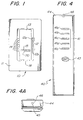
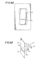
- FIG. 1 shows a front view of a preferred embodiment of a power
control and receiver unit in accordance with the present invention;
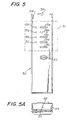
- FIG. 2 shows a top view of a preferred embodiment of a hand held
basic remote control unit for use with the unit of FIG. 1;
- FIG. 2A shows a left side view of the basic remote control unit
as shown in FIG. 2;
- FIG. 2B shows a right side view of the basic remote control unit
as shown in FIG. 2;
- FIG. 2C shows an end view of the basic remote control unit shown
in FIG. 2;
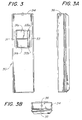
- FIG. 3 shows a top view of a preferred embodiment of a wireless
enhanced transmitter unit;
- FIG. 3A shows a right side view of the enhanced transmitter unit
as shown in FIG. 3;
- FIG. 3B shows an end view of the enhanced transmitter unit as
shown in FIG. 3;
- FIG. 4 shows a top view of an alternative preferred wireless
transmitter unit;
- FIG. 4A shows an end view of the wireless transmitter unit shown
in FIG. 4;
- FIG. 5 shows a top view of an alternative embodiment of a
preferred wireless enhanced transmitter;
- FIG. 5A shows an end view of the alternative enhanced
transmitter unit as shown in FIG. 5;
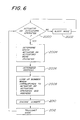
- FIG. 6 shows a functional flow diagram of the operation of the
transmitter units;
- FIG. 7 shows top plan view of a preferred embodiment of an
infrared lens;
- FIG. 8A illustrates the operation of the infrared lens shown in
FIG. 7, when infrared light at an incident ray angle of 0° passes
through lens;
- FIG. 8B illustrates the operation of the infrared lens shown in
FIG. 7, when infrared light at an incident ray angle of 40° passes
through lens;
- FIG. 8C illustrates the operation of the infrared lens shown in
FIG. 7, when infrared light at an incident ray angle of 80° passes
through lens;
- FIG. 9A illustrates the installation of the infrared lens
located in a moveable surface;
- FIG. 9B is an isometric illustration of the infrared lens
located in a moveable surface and an infrared detector;
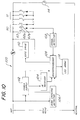
- FIG. 10 shows a block diagram of the circuitry of the receiver
unit shown in FIG. 1;
- FIG. 11 shows a block diagram of the circuitry of the basic
remote control unit shown in FIG. 2;
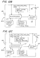
- FIG. 12A shows a block diagram of the circuitry the enhanced
remote control unit shown in FIG. 3;
- FIG. 12B shows a block diagram of the circuitry of the enhanced
remote control unit shown in FIG. 4; and
- FIG. 12C shows a block diagram of the circuitry of the enhanced
remote control unit shown in FIG. 5.
-
-
Referring now to the drawings, wherein like numerals indicate
like elements, there is shown in FIG. 1 a power control and infrared
receiving control unit 10 embodying a power control device for
controlling electric power delivered to at least one electrical device
(not shown). The control unit 10 comprises a cover plate 11 and a
plurality of control actuators comprising a user actuatable power
level selection actuator 12, a user actuatable control switch actuator
13, hereinafter referred to as a toggle switch actuator 13, and an air
gap switch actuator 18 which controls an air gap switch (not shown)
for removing all electric power to the control unit 10. The control
unit 10 further comprises a power level indicator in the form of a
plurality of individual LEDs 14 arranged in a line.
-
The control unit 10 further comprises an infrared (IR) receiving
lens 70 located in an opening 15 on the toggle switch actuator 13.
The lens 70 captures IR control signals that are transmitted by any
one of a number of wireless transmitter units 20, 30, 40, 50,
described below. The structure of infrared receiving lens 70 will be
described in more detail below.
-
In use, power control signals are transmitted to the control
unit 10 by a wireless hand held user actuatable basic remote control
20 or a wireless hand held user actuatable enhanced remote control 30, 40, 50,
depicted in FIGS. 2, 3, 4, and 5, respectively.
-
The control unit 10 embodies a
power control and infra-red receiver circuit 100 shown in Fig. 10, for controlling
one or more electrical devices. The control unit 10 is designed to control the electric
power delivered to at least one electrical device.
-
Preferably, the electrical device controlled by control unit 10 is an
electric lamp or lamps 114, as shown in Fig. 10. The control unit 10 controls the
electric power delivered to, and hence the light intensity of, the electric lamp or
lamps 114 in known manner by using a phase controlled triac circuit or otherwise.
-
However, it is to be understood that the electrical device could be
a fan, a motor, a relay, etc. In addition, the type of lamp 114 controlled is not
limited to an incandescent lamp but could be a low voltage incandescent lamp, a
fluorescent lamp, or other type of lamp.
-
The preferred embodiments described below are described in the
context of the electrical device being a lamp or lamps 114 and the control unit 10
controlling the intensity of these lamps.
-
When the electrical device includes at least one lamp, the at least one
lamp defines a lighting zone (hereinafter zone.) By incorporating multiple control
units 10, multiple zones can be created and controlled. The zones are used to create
lighting scenes (hereinafter scenes) by controlling the power level, and therefore the
intensity, of the lamps associated with one or more zones, thereby creating a plurality
of scenes. Therefore, multiple scenes can be created with one or more power control
units 10, which can be controlled by the control unit or the remote transmitters 20,
30, 40, 50.
-
Hereinafter, the terms "actuation" or "actuated" mean either opening,
closing, or maintaining closed for a particular period of time, a switch having one
or more poles. In the preferred embodiment of the invention the switches are
momentary contact switches and actuation is caused by the application of pressure
to the switch actuator of sufficient force to either open or close a switch. However,
other types of switches could be used.
POWER CONTROL AND RECEIVER UNIT
-
Referring to FIG. 1, the power level selection actuator 12 is actuated
by the user to set a desired level of light intensity of the one or more electric lamps
controlled by the control unit 10. The selection actuator 12 further comprises an
upper power level selector portion 12a and a lower power level selector portion 12b,
controlling respective power level selector switches 62a, 62b shown in FIG. 10.
-
The upper power level selector portion 12a, when actuated, causes
an increase or "RAISE" in intensity of the lamps controlled by the control unit 10.
Conversely, the lower power level selector portion 12b, when actuated with control
unit 10 in the on state, causes a decrease or "LOWER" in intensity of the lamps
controlled by the control unit 10. In addition, if the lower power level selector
portion 12b is actuated when control unit 10 is in the off state, it can be used to set
and store a delay to off time. The longer the lower power level selector 12b is
actuated, the longer the delay time to be set and stored.
-
The actuation of user actuatable control switch actuator 13 causes
control unit 10 to respond in a variety of ways, depending on the precise nature of
the actuation of control switch actuator 13 which actuates control switch 63, i.e.,
whether it is actuated for a transitory period of time or a longer than transitory period
of time, or whether it is actuated for several transitory periods of time in quick
succession, and also depending on the state of the control unit 10 prior to the
actuation of the control switch actuator 13.
-
In the present, an actuation has a transitory duration if the duration
of the actuation is less than 0.5 seconds. Two successive actuations of the actuator,
in rapid succession (double tap), refers to two transitory actuations that are within
0.5 seconds of each other. Three successive actuations of an actuator, in rapid
succession (triple tap), refers to three transitory actuations all within 1.0 second.
Four successive actuations of an actuator, in rapid succession (quad tap), refers to
four transitory actuations all within 1.5 seconds.
-
Although these time periods are presently preferred for determining
whether a double tap, triple tap, or quad tap actuations has occurred, any short
period of time may be employed without departing from the invention. For example,
a time period of 1.5 seconds could be used for determining whether a double tap,
triple tap, or a quad tap has occurred so that in an alternative embodiment of the
invention, if two successive actuations of transitory duration occurred in 1.5 seconds
it would be considered a double tap. The period of time during which multiple
successive actuations of transitory duration are looked for is considered to be a short
duration of time.
-
It is also possible to have an actuation of an actuator for more than
0.5 seconds, which is considered to be extended in nature and has an extended
duration.
-
The responses to the actuation of the control switch actuator 13 are
to increase the light intensity from zero to a preset level (FADE TO PRESET),
increase the light intensity to maximum (FADE TO FULL), decrease the light
intensity to zero (FADE TO OFF), decrease the light intensity to zero after a delay
(DELAY TO OFF), store a preset light level in memory (LOCKED PRESET), and
remove a preset light level from memory (DISCONTINUE LOCKED PRESET).
These features are executed by means of circuitry associated with the control unit
10 and depicted in a block diagram 100, shown in Fig. 10, described in detail in
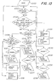
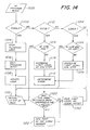
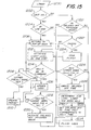
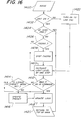
the flow charts illustrated in Figs. 13-20.
-
A FADE TO PRESET response is effected by a single actuation of
transitory duration of the user actuatable control switch actuator 13 when the control
unit 10 is in the off state, thereby causing the intensity of the electric lamp 114 to
increase at a first fade rate, from zero to a preset intensity level. This can be either
a locked preset level or the level at which the lamp was illuminated when the control
unit 10 was last in an on state, as will be described in more detail below.
-
A FADE TO FULL response is effected by a double actuation, i.e.,
two actuations of transitory duration in rapid succession, of the user actuatable
control switch actuator 13 (double tap), thereby causing the intensity of the electric
lamp 114 to increase, at a second fade rate, from an off state or any intensity level
to a maximum intensity level.
-
A FADE TO OFF response is effected by a single actuation of
transitory duration of the user actuatable control switch actuator 13, thereby causing
the intensity of the electric lamp 114 associated with the control unit 10 to decrease,
at a third fade rate, from any intensity level to an off state.
-
A DELAY TO OFF response is effected by an "extended" actuation,
i.e., a more than transitory actuation of the user actuatable control switch actuator
13, thereby causing the intensity of electric lamp 114 to decrease at the third fade
rate, from any intensity level to an off state after a delay time. The duration of the
delay time i.e., how long the delay time lasts from beginning to end, is dependent
on the length of time the control switch actuator 13 is actuated. In the preferred
embodiment the delay time is linearly proportioned to the length of time the control
switch actuator 13 is actuated.
-
Actuations of less than 0.5 sec. are considered to be transitory or of
short duration. Actuation of greater than 0.5 sec. cause an increase in the delay time
of 10 seconds for each additional 0.5 second that control switch actuator 13 is
actuated. Hence, if the control switch actuator 13 is held for two seconds, the delay
time would be 30 seconds.
-
A variable fade to off could also be effected by an "extended" actuation
of the control switch actuator 13, causing the intensity of electric lamp 114 to
decrease from any intensity to off with a variable fade rate. The variable fade rate
is dependent on the duration of the actuation. Whether the unit has variable delay
or variable fade to off on extended actuation of the control switch actuator 13 is
dependent on the programming of the microprocessor 108 shown in Fig. 10.
-
A LOCKED PRESET response is effected by a triple actuation, i.e.,
three actuations of transitory duration in rapid succession of the user actuatable
control switch actuator 13 (triple tap). The intensity of the lamp 114 does not change
but the intensity level is stored in a memory as a locked preset level, and subsequent
changes to the intensity level of the lamp do not affect the locked preset level.
-
A DISCONTINUE LOCKED PRESET response is effected by a
quadruple actuation, i.e., four actuations of transitory duration in rapid succession
of the user actuatable control switch actuator 13 (quadruple tap). The intensity of
the lamp 114 does not change, but any intensity level stored in memory as a locked
preset level is cleared.
-
If a locked preset level is stored in memory and the control unit 10
is in an off state then a FADE TO PRESET response causes the intensity of the
electric lamp 114 to increase to the locked preset level. If no locked preset level
is stored in memory and the control unit 10 is in an off state, then a FADE TO
PRESET response causes the intensity of the electric lamp 114 to increase to the
level at which the lamp 114 was illuminated when the control unit 10 was last in
an ON state.
-
Although the process of storing and clearing a locked preset level
has been described with reference to multiple actuations of the control switch actuator
13, this could also be accomplished by using two additional separate switches, one
to store a locked preset level and one to clear the locked preset level, or by using
one additional switch, successive actuations of which would alternately store and
clear the locked preset power level.
-
If a delay time has been stored by actuating the lower power level
selector portion 12b when the control unit 10 is in the off state as described above,
then a FADE TO OFF response effected by a single actuation of transitory duration
of the user actuatable control switch actuator 13 when the control unit 10 is in the
on state causes the lights to remain at their present intensity for the duration of the
stored delay time and then to decrease at a third fade rate to an off state.
-
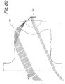
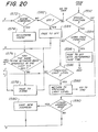
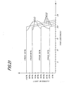
FIG. 21 illustrates delay to off profiles for a 20 second delay to off
of the control unit 10. The profiles show how the light intensity levels of the lamp
114 change, starting from their current intensity level for four different beginning
intensity levels. The lamp 114 remains at the current intensity level for the delay
time in this case 20 seconds before the intensity of the lamp decreases to zero. The
delay to off time is variable and the preferred embodiment has a variable delay to
off time range of 10 to 60 seconds in 10 second increments. Although these delay
times are presently preferred, it should be understood that the delay to off times and
the associated fade rate to off at the end of the delay time are not the only ones
which may be used with the invention, and any desired delay, fade rate or
combination thereof may be employed without departing from the invention.
-
The control unit 10 will remain at the current intensity level 600 for
the duration of the delay time. At the end of the delay time, the intensity of the lamp
114 decreases to zero. A suitable fade rate 602 for the decrease to zero may be 33%
per second. Preferably the delay times and fade rates are stored in the form of
digital data in the microprocessor 108, and may be called up from memory when
required by the delay to off routine also stored in memory.
-
The delay to off profiles illustrated in FIG. 21 for a 20 second delay
and similar profiles for the other possible delay to off times are used whether the
control unit 10 is performing a DELAY TO OFF in response to an extended
actuation of control switch actuator 13 or it is delaying to off with a previously stored
delay time in response to transitory actuation of control switch actuator 13.
-
The control unit 10 and the cover plate 11 need not be limited to any
specific form, and are preferably of a type adapted to be mounted to a conventional
wall box commonly used in the installation of lighting control devices.
-
The selection actuator 12 and the control switch actuator 13 are not
limited to any specific form, and may be of any suitable design which permits
actuation by a user. Preferably, although not necessarily, the actuator 12 controls
two separate momentary contact push switches 62a, 62b, but may also control a
rocker switch, for example. Actuation of the
upper portion 12a of the actuator 12 increases or raises the light intensity level, while
actuation of lower portion 12b of the actuator 12 decreases or lowers the light
intensity level. Preferably, but not necessarily, the actuator 13 controls a push-button
momentary contact type switch 53, but the switch 53 may be of any other suitable
type without departing from the scope of the present invention.
-
Similarly, although the effect of actuating the control switch actuator
13 is described above with respect to specific actuation sequences of control switch
13 having specific effects, i.e., FADE TO FULL is effected by a double tap and
LOCKED PRESET is effected by a triple tap, the linkage between the specific
actuation sequence and the specific effect can be changed.
For example, in an alternative embodiment of
the invention, FADE TO FULL could be effected by a triple tap.
-
The control unit 10 includes an intensity level indication in the form
of a plurality of intensity level indicators 14. The indicators are preferably, but need
not be, light-emitting diodes (LEDs) or the like.
Intensity
level indicators 14 are arranged, in this embodiment, in a linear array representing
a range of light intensities of the one or more lamps controlled by the control unit
10. The range of light intensities is from a minimum (zero, or "off") to a maximum
intensity level ("full on"). A visual indication of the light intensity of the controlled
lights is displayed by the illumination of a single intensity level indicator 14
preferably at 100% of its output when the lamps are on.
-
The intensity level indicators 14 of the preferred embodiment illustrated
in FIG. 1 show seven indicators aligned vertically in a linear array. By illuminating
the uppermost indicator in the array, maximum light intensity level is indicated.
By illuminating the center indicator, an indication is given that the light intensity
level is at about the midpoint of the range, and by illuminating the lowermost
indicator in the array, the minimum light intensity level is indicated.
-
Any convenient number of intensity level indicators 14 can be used.
By increasing the number of indicators in an array, the finer the gradation between
intensity levels within the range can be achieved. In addition, when the lamp or
lamps being controlled are off, all of the intensity level indicators 14 can be constantly
illuminated at a low level of illumination preferably at 0.5% of their maximum
output for convenience of the user. The indicator representing the actual intensity
level of the lamps when they return to the on state is illuminated at a slightly higher
illumination level, preferably at 2% of its maximum output. These illumination
characteristics enable the intensity level indicators 14 to be more readily perceived
by the eye in a darkened environment, thereby assisting a user in locating the switch
in a dark room, and constitute a "night light mode". An important feature of the
present invention, in addition to controlling the lights in the room, is to provide
sufficient contrast between the level indicators to enable a user to perceive the actual
intensity level at a glance.
-
The intensity level indicators 14 are also used to provide feedback
to the user of the control unit 10 regarding how the control unit 10 is responding
to the various actuations of control switch actuator 13 and selection switch actuator
12.
-
For example, when a FADE TO PRESET response is effected by
a single actuation of transitory duration of control switch actuator 13 when the
control unit 10 is in the off state, the intensity level indicators 14 change from the
"night light mode" to illuminating the lowermost indicator followed by illuminating
successively higher indicators in turn as the light intensity increases until the indicator
which indicates the intensity of the preset light level is illuminated.
-
Further, when a FADE TO FULL response is effected by a double
tap of the control switch actuator 13, the intensity level indicators change from their
original condition to illuminating successively higher indicators in turn until the
uppermost indicator in the array is illuminated as the light intensity increases to full.
-
Further, when a FADE TO OFF response is effected by a single
actuation of transitory duration of the control switch actuator 13 when the control
unit 10 is in the on state, the intensity level indicators 14 change from their original
condition to illuminating successively lower indicators in turn as the light intensity
decreases to its lowest level. Finally, the intensity level indicators 14 indicate the
"night light mode" when the light intensity decreases to zero.
-
Further, when a DELAY TO OFF response is effected by extended
actuation of the control switch actuator 13 when the control unit 10 is in the on state,
the intensity level indicators 14 first indicate the length of the delay time selected.
After the control switch actuator 13 has been held closed for 0.5 seconds, the
lowermost indicator will cycle on and off to indicate that a 10 second delay has been
selected, after a further 0.5 seconds the next highest indicator will cycle on and off
to indicate that a 20 second delay has been selected, and so on, with successively
higher indicators cycling on and off until the control switch actuator 13 is released.
-
When the control switch actuator 13 is released, the indicator
indicating the present light intensity level cycles on and off during the delay time.
At the end of the delay time, the indicator which indicates the present level is
illuminated and then successively lower indicators are illuminated as the light
decreases to its lowest level. Finally, the intensity level indicators 14 indicate the
"night light mode" when the light intensity decreases to zero.
-
When a LOCKED PRESET response is effected by a triple actuation
of the control switch actuator 13, the intensity level indicator indicating
the current light level of the lamp flashes twice at a frequency of 2Hz to indicate
that the intensity level has been successfully stored.
-
When a DISCONTINUE LOCKED PRESET response is effected
by a quadruple actuation of the control switch actuator 13, the intensity level
indicator indicating the current light level of the lamp flashes twice at a frequency
of 2Hz to indicate that the intensity level has been cleared from memory.
-
When a RAISE response is effected by actuation of the upper portion
12a of the selection actuator 12, the intensity level indicators 14 change from their
original condition to illuminating successively higher indicators in turn as the
actuation continues until either the actuation ends or the uppermost indicator in the
array is illuminated when the light intensity reaches a maximum.
-
When a LOWER response is effected by actuation of the lower
portion 12b of selection actuator 12 while the control unit 10 is in the on state, the
intensity level indicators 14 change from their original condition to illuminating
successively lower indicators as the actuation continues until either the actuation ends
or the lowermost indicator in the array is illuminated when the light intensity reaches
a minimum. The control unit 10 does not turn off.
-
Finally, if the lower portion 12b of the selection actuator 12 is
actuated when the control unit 10 is in the off state, the intensity level indicators 14
initially indicate the "night light mode". After the lower portion 12b has been
actuated for 4.0 seconds, the lowermost indicator will cycle on and off to indicate
that a 10 second delay has been selected, after a further 0.5 seconds the next highest
indicator will cycle on and off to indicate that a 20 second delay has been selected,
and so on, with successively higher indicators cycling on and off until the lower
portion 12b is released. When the lower portion 12b is released, the indicator
indicating the delay time selected flashes twice at a frequency of 2Hz to indicate that
the delay time has been successfully stored and then the intensity level indicators
14 return to the "night light mode".
WIRELESS TRANSMITTER UNITS
-
One embodiment of a basic infrared signal transmitting wireless
remote control unit 20 suitable for use with the control unit 10 is shown in FIGS.
2, 2A, 2B and 2C.
-
The basic wireless control unit 20 comprises a plurality of control
actuators, comprising a user actuatable transmitter power level selection actuator 23 and associated intensity selection switches 223 and a user actuatable transmitter
control switch actuator 21 and associated transmitter control switch 221. Transmitter
selection actuator 23 further comprises an increase power level selector portion 23a
and a decrease power level selector portion 23b, controlling respective intensity
selection switches 223a, 223b.
-
The basic wireless control unit 20 further comprises an infra-red
transmitting diode 26 which is located in an opening 25 in an end 24 of the basic
wireless control unit 20 as best seen in FIG. 2C. Alternatively, basic wireless
control unit 20 can further comprise an address switch 222 and an address switch
actuator 22, which may be used in conjunction with a "send address" switch (not
shown) as will be described in more detail below. The switches 221, 222, 223a,
223b are shown in FIG. 11.
-
Actuation of the increase power level selector portion 23a, the lower
power level selector portion 23b, or the transmitter control switch actuator 21 of
basic wireless remote control unit 20 generally has the same effect as actuating the
upper power level selector portion 12a, the lower power level selector portion 12b
or the control switch actuator 13 respectively of the control unit 10.
-
The actuation of the actuators 23a, 23b, 21 on the basic wireless
remote control unit 20 closes the respective switches 223a, 223b, 221 which they
actuate. The switch closure is detected by a microprocessor 27 and the information
about which actuator has been operated is transmitted via infra-red signals from the
infra-red transmitting diode 26 as will be described in more detail below in
connection with the description of FIGS. 6 and 11.
-
The infrared signals are detected by an infra-red receiver 104 and
the signal information is passed to a microprocessor 108 which interprets the signal
information as will be described in more detail below in connection with the
description of FIGS. 10 and 13 to 20.
-
In general, actuating an actuator on the basic wireless remote control
unit 20 has the same effect as operating the corresponding actuator on the control
unit 10. Thus, actuating the transmitter control switch actuator 21 for a transitory
period of time will have the same effect as operating the control switch actuator 13
on the control unit 10 for a transitory period of time. (As described above, the exact
effect may vary depending on the state of the control unit 10 prior to the actuation).
However, if desired, certain functions may be accessed only from the control unit
10 and not from basic wireless remote control unit 20 or vice versa. For example,
the triple tap of transmitter control switch actuator 21 could have no effect on the
control unit 10, whereas the triple tap of control switch actuator 13 could have the
effect described above.
-
One embodiment of an enhanced infra-red signal transmitting wireless
remote control unit 30 suitable for use with the control unit 10 is shown in FIGS.
3, 3A and 3B. The enhanced wireless control unit 30 comprises a plurality of
control actuators, comprising a user actuatable transmitter power level selection
actuator 33 and associated intensity selection switches 333, and a user actuatable
transmitter scene control actuator 31 and associated switches 331. Transmitter
selection actuator 33 further comprises an increase power level selector portion 33a
and a decrease power level selector portion 33b, controlling respective intensity
selection switches 333a and 333b, and scene the control actuator 31 further
comprises a scene select actuator 31a and an off actuator 31b controlling respective
scene control switches 331a, 331b.
-
The enhanced wireless control unit 30 further comprises an infra-red
transmitting diode 36 which is located in an opening 35 in an end 34 of the enhanced
wireless control unit 30 as best seen in FIG. 2B. Alternatively the enhanced wireless
control unit 30 can further comprise an address switch 332 and address switch
actuator (not shown but the same as the address switch actuator 22 used with the
basic wireless control unit 20). The switches 331a, 331b, 332, 333a, 333b are
shown in FIG. 12A.
-
Actuation of the increase power level selector portion 33a or the lower
power level selector portion 33b of the enhanced wireless control unit 30 generally
has the same effect as actuating the upper power level selector portion 12a or the
lower power level selector portion 12b of the control unit 10, respectively.
-
Actuation of the scene select actuator 31a for a transitory period of
time causes the light intensity of the electric lamp 114 to change at the first fade rate
from its present intensity level (which can be off) to a first preprogrammed preset
intensity level.
-
Actuation of the scene select actuator 31a for two transitory periods
of time in rapid succession causes the light intensity of the electric lamp 114 to
change at the first fade rate from its present intensity level (which can be off) to a
second preprogrammed preset intensity level.
-
The method for preprogramming the preset intensity levels will be
described in detail below.
-
Actuation of the off actuator 31b generally has the same effect as
actuating the control switch actuator 13 of the control unit 10 when the control unit
10 is in an on state and is delivering a non-zero power level to the lamp under
control; and has no effect when the control unit 10 is in an off state and delivering
zero power to the lamp. Hence, by actuating the off actuator 31b, it is possible to
effect a fade to off response or a delay to off response from the control unit 10.
-
The actuation of the actuators 33a, 33b, 31a, 31b which they actuate
on the enhanced wireless remote control unit 30 closes the respective switches 333a,
333b, 331a, 331b. The switch closure is detected by a microprocessor 47, and the
information about which actuator has been operated is transmitted via infra-red
signals from the infra-red transmitting diode 36 as will be described in more detail
below in connection with the description of FIGS. 6 AND 12A.
-
The infrared signals are detected by an infra-red receiver 104 and
the signal information is passed to a microprocessor 108 which interprets the signal
information as will be described in more detail below in connection with the
description of FIGS. 10 AND 13-20.
-
A second embodiment of an enhanced infra-red transmitting wireless
remote control unit 40 suitable for use with the control unit 10 is shown in FIGS.
4 AND 4A. The enhanced wireless control unit 40 comprises a plurality of control
actuators, comprising a user actuatable transmitter power level selection actuator
43 and associated intensity selection switches 443, and user actuatable transmitter
scene control actuators 41 and associated switches 441. The transmitter selection
actuator 43 is a paddle actuator which is moved upwards to actuate increase intensity
selection switch 443a and is moved downwards to actuate decrease intensity selection
switch 443b. The scene control actuators 41 comprise scene select actuators 41a,
41b, 41c, 41d and an off actuator 41e controlling respective scene control switches
441a, 441b, 441c, 441d, 441e.
-
The enhanced wireless control unit 40 further comprises an infra-red
transmitting diode 46 which is located in an opening 45 in an end 44 of the enhanced
wireless control unit 40 as best seen in FIG. 4A. Alternatively enhanced wireless
control unit 40 can further comprise an address switch 442 and an address switch
actuator (not shown but the same as the address switch actuator 22 used with the
basic wireless control unit 20). The switches 441a, 441b, 441c, 441d, 441e, 442,
443a, 443b are shown in FIG. 12B.
-
Actuation of increase intensity switch 443a by moving the transmitter
selection actuator upward generally has the same effect as actuating the upper power
level selector portion 12a of the control unit 10. Similarly, actuation of decrease
intensity selection switch 443b by moving the transmitter selection actuator
downward generally has the same effect as actuating the lower power level selector
portion 12b of the control unit 10.
-
Actuation of each of the scene select actuators 41a, 41b, 41c, 41d
for a transitory period of time causes the light intensity of the electric lamp 114 to
change at the first fade rate from its present intensity level (which can be off) to first,
second, third, and fourth preprogrammed preset intensity levels, respectively.
-
Actuation of each of the scene select actuators 41a, 41b, 41c, 41d
for two transitory periods of time in rapid succession causes the light intensity of
the electric lamp 114 to change at the first fade rate from its present intensity level
(which can be off) to fifth, sixth, seventh, and eighth preprogrammed preset intensity
levels, respectively.
-
The method for preprogramming the preset intensity levels will be
described in detail below.
-
Actuation of the off actuator 41e generally has the same effect as
actuating the control switch actuator 13 of the control unit 10 when the control unit
10 is in an on state and is delivering a non-zero power level to the lamp under
control; and has no effect when control unit 10 is in an off state and delivering zero
power to the lamp. Hence, by actuating the off actuator 41e, it is possible to effect
a fade to off response or a delay to off response from the control unit 10.
-
The actuation of the actuators 43, 41a, 41b, 41c, 41d, 41e on the
enhanced wireless remote control unit 30 closes the respective switches 443a, 443b,
441a, 441b, 441c, 441d, 441e which they actuate. The switch closure is detected
by a microprocessor 47, and the information about which actuator has been operated
is transmitted via infra-red signals from the infra-red transmitting diode 46 as will
be described in more detail below in connection with the description of FIGS. 6
AND 12B.
-
The infra-red signals are detected by an infra-red receiver 104 and
the signal information is passed to a microprocessor 108 which interprets the signal
information as will be described in more detail below in connection with the
description of FIGS. 10 AND 13-20.
-
A third embodiment of an enhanced infra-red transmitting wireless
remote control unit 50 suitable for use with the control unit 10 is shown in FIGS.
5 AND 5A.
-
The enhanced wireless control unit 50 comprises a plurality of control
actuators comprising a user actuatable transmitter power level selection actuator 53
and associated intensity selection switches 553, and user actuatable transmitter scene
control actuators 51 and associated switches 551. The transmitter selection actuator
53 is a paddle actuator which is moved upwards to actuate increase intensity selection
switch 553a and is moved downwards to actuate decrease intensity selection switch
553b. The scene control actuators 51 comprise scene select actuators 51a, 51b, 51c,
51d and an off actuator 51e controlling respective scene control switches 551a, 551b,
551c, 551d, 551e. The scene control actuator 51 further comprise special function
select actuators 51f, 51g, 51h, 51i controlling respective special function control
switches 551f, 551g, 551h, 551i.
-
The enhanced wireless control unit 50 further comprises an infra-red
transmitting diode 56 which is located in an opening 55 in an end 54 of the enhanced
wireless control unit 50 as best seen in FIG. 5A. Alternatively enhanced wireless
control unit 50 can further comprise an address switch 552 and an address switch
actuator (not shown but the same as the address switch actuator 22 used with the
basic wireless control unit 20). The switches 551a, 551b, 551c, 551d, 551e, 551f,
551g, 551h, 551i, 552, 553a, 553b are shown in FIG. 12C.
-
Actuation of increase intensity switch 553a by moving the transmitter
selection actuator upward generally has the same effect as actuating the upper power
level selector portion 12a of the control unit 10. Similarly, actuation of decrease
intensity selection switch 553b by moving the transmitter selection actuator
downward generally has the same effect as actuating the lower power level selector
portion 12b of the control unit 10.
-
Actuation of each of the scene select actuators 51a, 51b, 51c, 51d
for a transitory period of time causes the light intensity of the electric lamp 114 to
change at the first fade rate from its present intensity level (which can be off) to first,
second, third, and, fourth preprogrammed preset intensity levels, respectively.
-
Actuation of each of the scene select actuators 51a, 51b, 51c, 51d
for two transitory periods of time in rapid succession causes the light intensity of
the electric lamp 114 to change at the first fade rate from its present intensity level
(which can be off) to fifth, sixth, seventh, and eighth preprogrammed preset intensity
levels, respectively.
-
The third embodiment 50 of the enhanced transmitter differs from
the second embodiment 40 of the enhanced transmitter in that it further comprises
special function actuators 51f, 51g, 51h, 51i controlling respective special function
switches 551f, 551g, 551h, 551i. These special function actuators can be used to
select ninth, tenth, eleventh, and twelfth preprogrammed preset intensity levels,
respectively, or to select special functions. Alternatively, some special function
actuators can be used to select preprogrammed preset intensity levels and some can
be used to select special functions.
-
The method for preprogramming the preset intensity levels and the
nature of. the special functions will be described in detail below.
-
Actuation of the off actuator 51e generally has the same effect as
actuating the control switch actuator 13 of the control unit 10 when the control unit
10 is in an on state and is delivering a non-zero- power level to the lamp under
control; and has no effect when control unit 10 is in an off state and delivering zero
power to the lamp. Hence, by actuating the off actuator 51e, it is possible to effect
a fade to off response or a delay to off response from the control unit 10.
-
The actuation of the actuators 53, 51a, 51b, 51c, 51d, 51e, 51f, 51g,
51h, 51i on the enhanced wireless remote control unit 30 closes the respective
switches 553a, 553b, 551a, 551b, 551c, 551d, 551e, 551f, 551g, 551h, 551i which
they actuate. The switch closure is detected by a microprocessor 47, and the
information about which actuator has been operated is transmitted via infra-red
signals from the infra-red transmitting diode 56 as will be described in more detail
below in connection with the description of FIGS. 6 AND 12C.
-
The infra-red signals are detected by an infra-red receiver 104 and
the signal information is passed to a microprocessor 108 which interprets the signal
information as will be described in more detail below in connection with the
description of FIGS. 10 AND 13-20.
-
The method for preprogramming the preset intensity levels accessed
from the enhanced wireless control units 30, 40, 50 is similar for each of the
enhanced remote controls.
-
Programming mode for the control unit 10 is entered by actuating
a combination of actuators on the enhanced remote controls and keeping the switches
controlled by the actuators closed for a certain length of time, preferably 3 seconds,
while transmitting infra-red signals from the transmitter to control unit 10 at which
time the control unit 10 enters programming mode.
-
For the embodiment of the enhanced remote control 30 illustrated
in FIGS. 3, 3A AND 3B, programming mode is entered by actuating the scene select
actuator 31a and the off actuator 31b at the same time. For the embodiment 40
illustrated in FIGS. 4 AND 4A, programming mode is entered by actuating the scene
select actuator 41a and the off actuator 41e at the same time. For the embodiment
50 illustrated in FIGS. 5 AND 5A, programming mode is entered by actuating the
scene select actuator 51a and the off actuator 51e at the same time.
-
The control unit 10 enters the programming mode ready to program
the first preset intensity level. The uppermost indicator 14 (which is indicating that
the first preset intensity level is being programmed) flashes on and off with a duty
cycle of approximately 10% and the indicator 14 corresponding to the light intensity
level currently programmed as the first preset intensity level flashes on and off with
a 90% duty cycle. Duty cycle here refers to the relative amount of time that one
indicator 14 is on as opposed to another indicator 14 being on. Only one indicator
14 is ever illuminated at one time due to constraints within the power supply
powering the indicator 14.
-
The light intensity level to be stored is adjusted by actuating the
increase power level selector portion 33a or lower power level selector portion 33b
or the off actuator 31b for the embodiment of the enhanced remote control 30
illustrated in FIGS. 3, 3A AND 3B, by actuating the power level selection actuator
43 either up or down to actuate increase intensity selection switch 443a or decrease
intensity selection switch 443b or the off actuator 41e for the embodiment of the
enhanced remote 40 illustrated in FIGS. 4 AND 4A, by actuating the power level
selection actuator 53 either up or down to actuate increase intensity selection switch
553a or decrease intensity selection switch 553b or the off actuator 51e for the
embodiment of the enhanced remote 50 illustrated in FIGS. 5 AND 5A. For all
embodiments of the enhanced remote control 30, 40, 50, the light intensity to be
stored can also be adjusted by actuating the upper power level selection portion 12a
and the lower power level selector portion 12b of the control unit 10.
-
As the intensity is adjusted, the light intensity of electric lamp 114
changes and the indicator 14 which is illuminated with a 90% duty cycle also changes
to indicate the new current light level.
-
Once the desired intensity level to be programmed as the first preset
intensity level (which may be off), has been reached either another preset intensity
level to be programmed is selected or programming mode is exited. In the case of
the enhanced remote control 30 illustrated in FIGS. 3, 3A AND 3B, only a first
preset intensity level can be programmed, so the only option at this point is to exit
programming mode.
-
If it is desired to program another preset intensity level, then this is
selected by actuating a scene select actuator 41b, 41c, 41d for a transitory period
of time for the embodiment of the enhanced remote control illustrated in FIGS. 4
AND 4A or a scene select actuator 51b, 51c, 51d for a transitory period of time
for the embodiment of the enhanced remote control illustrated in FIGS. 5 AND 5A.
-
These scene select actuators select second, third, and fourth preset
intensity levels to be programmed respectively. The second highest indicator 14
flashes on and off with a 10% duty cycle when the second preset intensity level has
been selected, the third highest indicator 14 flashes on and off with a 10% duty cycle
when the third preset intensity level has been selected and the middle indicator 14
flashes on and off with a 10% duty cycle when the fourth preset intensity level has
been selected.
-
Actuating a scene select actuator 41a, 41b, 41c, 41d, 51a, 51b, 51c,
51d for two transitory periods of time enables the selection of the fifth, sixth,
seventh, and eighth preset intensity levels to be programmed, respectively.
-
The highest, second highest, third highest, and middle indicator 14
will flash on and off with a duty cycle other than 10% to indicate that either the fifth,
sixth, seventh, or eighth preset intensity level to be programmed has been selected.
-
If the embodiment of the enhanced transmitter 50 illustrated in FIGS.
5 AND 5A is being used to select ninth, tenth, eleventh, and twelfth preset intensity
levels from the special function actuators 51f, 51g, 51h, 51i, these can be selected
for programming by actuating a special function actuator 51f, 51g, 51h, 51i.
-
The highest, second highest, third highest, and middle indicator 14
will flash on and off with a second duty cycle other than 10% to indicate that either
the ninth, tenth, eleventh, or twelfth preset intensity level to be programmed has
been selected.
-
The light intensity to be stored is adjusted in the same manner as
described above for programming the first preset intensity level.
-
Once all the desired preset intensity levels have been programmed,
programming mode is exited by actuating the same combination of actuators which
were used to enter programming mode again for a period of time, preferably 3
seconds, while transmitting infra-red signals from the transmitter to the control unit
10. At the end of the period, the control unit exits programming mode.
Alternatively, programming mode can be exited by actuating actuator 13 on control
unit 10 for a transitory period of time.
-
The operation of the special function actuators 51f, 51g, 51h, 51i
on the enhanced transmitter 50 is dependant on the particular special functions
programmed into the control unit 10 which receives the infrared signals.
-
One alternative is to use the special function selection actuator to
select additional programmed intensity levels as described above. A first special
function which can be selected by a first special function actuator is "FADE TO OFF
WITH DETERMINED FADE TIME". This function is similar to "DELAY TO
OFF" except that, whereas in the case of the "DELAY TO OFF" the light intensity
of lamp 114 remains at its current intensity during the delay time and then decreases
to zero over a relatively short period of time, in the case of "FADE TO OFF WITH
DETERMINED FADE TIME" the light intensity level of lamp 114 immediately
begins to decrease in value once the actuator is released and then continues to
decrease in value until it reaches zero at the end of the "DETERMINED FADE
TIME".
-
The "DETERMINED FADE TIME" is determined by the length of
time that the first special function actuator has been actuated. The longer the
actuator is actuated, the longer the fade time.
-
After the first special function actuator has been actuated the indicator
14 will flash the lowest LED to indicate a fade time of 10 sec has been selected.
For each additional 0.5 sec that the first special function actuator is actuated the fade
time increases by 10 sec to a maximum of 60 sec. Successively higher indicators
14 are flashed to indicate the increasing fade time selected. When the first special
function actuator is released, the decrease in light intensity of lamp 114 begins to
occur and the indicator 14 indicating the current light intensity is flashed.
Successively lower indicators 14 are flashed as the light intensity of lamp 14 is
decreased until the indicator 14 indicates the "Night light mode" when lamp 114 is
at zero power.
-
A second special function which can be selected by a second special
function actuator is "RETURN TO PREVIOUS LIGHT LEVEL". This function
causes the light intensity of lamp 114 to return to the last preset level it had prior
to the last actuation of a scene select actuator, a control switch actuator, or a power
level selector actuator.
-
In this way it is possible for the user of the control unit 10 to return
to the last selected preset level which could be a preprogrammed preset intensity
level, a locked preset intensity level or an unlocked preset intensity level. The
intensity level of lamp 114 will gradually increase or decrease from the current
intensity level to the intensity level being returned to, and the indicator 14 will
change from illuminating the LED corresponding to the current intensity level to
illuminating successively higher or lower LEDs until the indicator 14 indicating the
intensity level of the last selected preset level is illuminated.
-
Other special functions can optionally be programmed into the control
unit 10 and selected by actuating different special function actuators.
-
The operation of the optional address switch actuator 22 and address
switch 222, 332, 442, 552 and the send address switch (not shown) is similar for
the basic wireless control unit 20, and the three embodiments of the enhanced
wireless control unit 30, 40, 50.
-
The first use of the optional address switch actuator 22 and the send
address switch is to label control unit 10 with a particular address. Address switch
actuator 22 controls an address switch, 222, 332, 442, 552 which is typically a
multiposition switch, for selecting between different address A, B, C, D, etc. If
it is desired to label a particular control unit 10 with address B, then the address
switch actuator would be adjusted to select B, and then the send address switch
would be actuated. The send address switch is not shown, but could have any
desired form. Preferably, the send address switch is actuated by a small and
inconspicuous actuator since it is used infrequently. Alternatively, the actuator for
the send address switch could be hidden under normal use for, for example under
a battery compartment cover for the wireless control unit 20, 30, 40, 50.
-
Alternatively in the case of the three embodiments of enhanced
wireless control unit 30, 40, 50, the function of the send address switch could be
obtained by actuating a combination of the existing actuators, for example the off
actuator 31b, 41e, 51e and the upper power level selector portion 33a, or moving
the transmitter selection actuator 43, 53 upwards.
-
After the send address switch has been actuated or the appropriate
combination of actuators has been actuated, an infrared signal is sent from the
wireless control unit 20, 30, 40, 50 which commands any control unit 10 which
receives the signal to label itself with address B. The intensity level indicator 14
indicating the current intensity level of the lamp flashes three times at a frequency
of 2Hz to indicate that the address has been successfully received and stored in a
memory.
-
Alternatively, the intensity level indicator 14 indicating the current
intensity level of the lamp 114 flashes at a frequency of 2Hz until the control switch
actuator 13 is actuated for a transitory period of time to store the address in memory.
If actuator 13 has not been actuated within 2 minutes of the control unit 10 receiving
the infra-red signal, then no address is stored and the control unit 10 returns to the
state which it was in prior to receiving the infra-red signal.
-
In this way, it is possible to label a plurality of control units 10 with
the same or different addresses.
-
Once all the control units 10 desired to be controlled by the wireless
control unit 20, 30, 40, 50 have been labelled with addresses, then the wireless
control unit 20, 30, 40, 50 can be used to control only those control units 10 which
have been labelled with a particular address in the following manner.
-
The address switch actuator 22 is adjusted to the position which
selects the address of the control units 10 which were desired to be controlled, for
example A. After that has been done, any signals sent from wireless control unit
20, 30, 40, 50 in response to the actuation of the other actuators, for example scene
select actuation 31, 41, 51 or transmitter selection actuator 33, 43, 53 contain address
information A.
-
Only those control units 10 which have previously been labelled with
address A will respond to the infra-red signals which contain address information
A. Other control units 10 will not respond. In this way, by labelling a plurality
of control units 10 with different addresses, it is possible to control each control unit
10 individually, even if all units receive the infra-red signals.
-
It is also possible for the address switch actuator 22 to select an ALL
address. This cannot be used to label control units 10. However, once the control
units 10 have been labelled with individual addresses A, B, C, etc., then selecting
the ALL address with the address switch actuator 22 causes the infra-red signals
transmitted from wireless control unit 20, 30, 40, 50 to contain an ALL address.
In this case, all control units 10 which receive the infra-red signals with the ALL
address will respond regardless of the individual addresses with which they have
been labelled.
-
Turning to FIG. 10, the circuitry of the power control unit 10 is
depicted in the control unit block diagram 100. The circuitry, with the exception
of wireless remote control operation, is well known to one skilled in the art, and
is fully described in U.S. Patent 5,248,919.
Therefore, a detailed description of the circuit is not reproduced
herein, and only the new features of the system are described below.
-
The preferred embodiment of the present invention provides the
features of wireless remote control operation, as described below, in combination
with the light control disclosed in U.S. Patent 5,248,919. In the preferred
embodiment of the present invention, the circuitry of the power control unit 10 is
commanded by infra-red control signals transmitted by wireless remote control units
20, 30, 40, 50, (shown in FIGs. 2, 3, 4 and 5, respectively) in addition to being
commanded by actuators located on the power control unit 10. An infrared receiver
104 responds to the infra-red control signals and converts them to electrical control
signal inputs to a microprocessor 108 in a similar manner to which the signal detector
102 responds to control signals from switches 110 located in power control unit 10
as well as control signals from switches 111 within wired remote lighting control
units and provides control signal inputs to microprocessor 108 of the present
invention are similar to the control signals, signal detector 32, and microprocessor
28 disclosed in U.S. Patent 5,248,919. However, the program running is different
and provides additional functions and features not disclosed in U.S. Patent
5,248,919.
-
In the present invention, control signal inputs are generated by switch
actuators on the power control unit 10, by switch actuators on a user actuatable
wireless remote control unit 20, 30, 40, 50, or on wired remote lighting control
units. In each case, these signals are directed to the microprocessor 108 for
processing. The microprocessor 108 then sends the appropriate signals on to the
remaining portion of the control circuitry which in turn control the intensity levels
and state of the lamp 114 associated with the control unit 10.
-
A block diagram of the control circuit 200 of basic remote control
unit 20 is depicted in FIG. 11. The intensity selection actuator 23 actuates intensity
selection switches 223a or 223b and the control switch actuator 21 actuates
transmitter control switch 221 to provide inputs to a microprocessor 27. The
microprocessor 27 provides encoded control signals to an LED drive circuit 28,
which drives an LED 26 to produce and transmit infrared signals encoded by the
microprocessor 27. The LED 26 is located in the IR transmitter opening 25,
embodied in the end wall 24 of the user actuatable basic remote control unit 20.
-
The address switch actuator 22 actuates the address switch 222 to
provide inputs to the microprocessor 27. A "SEND ADDRESS" switch not shown
in FIG. 11 would also provide input to the microprocessor 27 as described above.
-
Battery 49 provides power to basic remote control unit 20.
-
The microprocessor 27 has a preprogrammed software routine which
controls its operation. The operation of the routines in the microprocessor 27 is
illustrated in flow chart form in FIG. 6. There is one major flow path, or routine,
which the program in the microprocessor 27 follows. This path is selected whenever
the "ACTUATOR OR ACTUATORS OPERATED?" decision node 2000 is "yes".
This occurs whenever the control switch actuator 21 or the power level selection
actuator 23 is actuated. Following the "ACTUATOR OR ACTUATORS
OPERATED?" decision node is the "DETERMINE WHICH ACTUATOR OR
ACTUATORS WERE OPERATED?" node 2004 where a determination is made
as to which actuator or actuators were operated. Following the "DETERMINE
WHICH ACTUATOR OR ACTUATORS WERE OPERATED" node 2004 is the
"DETERMINE ADDRESS" node 2006, where the microprocessor 27 determines
the setting of the address switch 222. The microprocessor 27 then proceeds to
"LOOK UP A NUMBER WHICH CORRESPONDS TO THE ACTUATOR OR
ACTUATORS OPERATED AND THE ADDRESS SELECTED" 2008. The
microprocessor then "ENCODES NUMBER" 2010 and then "TRANSMITS CODE"
2012.
-
If the control switch actuator 21 or power level selection actuator 23
is not actuated by a user, the remote control unit 20 enters a "SLEEP MODE" 2002
and no change is made to the state of the control unit 10.
-
A block diagram of each of the control circuits 300, 400, 500 of the
enhanced wireless remote control units 30, 40, 50 is depicted in FIGS. 12A, 12B,
12C. These block diagrams are very similar to the block diagram 200 shown in
FIG. 11 with the scene control switches 331a, 331b in the block diagram 300
replacing the transmitter control switch 221 in the block diagram 200, the scene
control switches 441a, 441b, 441c, 441d, 441e in the block diagram 400 replacing
the transmitter control switch 221 in the block diagram 200, and the scene control
switches 551a, 551b, 551c, 551d, 551e, and special function switches 551f, 551g,
551h, 551i in the block diagram 500 replacing the transmitter control switch 221
in the block diagram 200.
-
The scene control switches provide inputs to the microprocessor 47.
The microprocessor 47 provides encoded control signals to an LED drive circuit
48 which drives an LED 36, 46, 56 to produce and transmit infrared signals encoded
by the microprocessor 47. These signals are transmitted through the IR opening 35, 45, 55 which is located in the end wall 34, 44, 54 of the enhanced wireless
remote control units 30, 40, 50.
-
An address switch actuator 22 of the enhanced remote control units
30, 40, 50 actuates the address switch 332, 442, 552 respectively to provide inputs
to the microprocessor 47. A send address switch, not shown in Figures 12A, 12B,
and 12C would also provide input to the microprocessor 47.
-
The enhanced remote control units 30, 40, 50 use the same
preprogrammed software routine to control their operation as depicted in FIG. 6.
The actual code running may be different. The "ACTUATOR OR ACTUATORS
OPERATED" decision node 2000 in FIG. 6 is "yes" whenever a scene control
switch or a power level intensity selector switch is actuated.
-
Turning to FIGs 13 through 20, the microprocessor 108 of the control
unit 10 has preprogrammed software routines which control its operation. The
operation of the routines in the microprocessor 108 is illustrated in flow chart form
in FIG 13 through 20. Referring to FIG 13, there are four major flow paths, or
routines, which the microprocessor 108 can follow. These paths are selected
depending on the source of the input control signals. The first three paths, RAISE
1030, LOWER 1024, and TOGGLE 1036 are selected when the power selection
actuator 12 or the control switch actuator 13 are actuated, as discussed above.
-
The function of the preprogrammed software routines for the
operation by wireless remote control will also be discussed in detail, this is the fourth
path, "IR SIGNAL" 1012.
-
Referring to FIG 13, the program begins at "MAIN" 1000 as shown.
The first decision node encountered is the "IN IR PROGRAM MODE?" 1002. The
program determines if the control unit 10 is in program mode so that
preprogrammed light intensities can be stored. If the output from "IN IR
PROGRAM MODE" decision node 1002 is "yes", the next decision node is "HAS
AN ACTUATOR OR IR SIGNAL BEEN RECEIVED WITHIN THE LAST TWO
MINUTES?" 1004. Decision node 1004 performs a time out function to determine
if the user is confused while in programming mode. If the user does not touch the
actuators on the control unit within two minutes, the unit will automatically exit from
program mode and stop flashing indicators 14 that are being flashed. If the output
from decision node 1004 is "no", the control unit 10 is commanded to "EXIT
PROGRAM MODE" 1026 and "STOP FLASHING LEDS" 1028 and the program
returns to "MAIN" 1000. If the output from decision node 1004 is "yes", the
program proceeds to the "ACTUATOR OPERATED?" decision node 1006. A check
is made as to whether any actuators have been actuated on the control unit 10 i.e.,
the power level selection actuator 12 or the control switch actuator 13.
-
If the output of the "ACTUATOR OPERATED?" decision node 1006
is "yes", the program proceeds to "IN IR PROGRAM MODE?" decision node 1018,
where a check is made as to whether the control unit 10 is in program mode again.
If the output of the "IN IR PROGRAM MODE?" decision node 1018 is "yes", the
program proceeds to "GO TO IR PROGRAM MODE ROUTINE" 1020. This is
shown in greater detail in the IR Program Mode routine 1100, shown in FIG 14.
-
If the output from decision node 1018 is "no", the program proceeds
to the "RAISE?" decision node 1030 where a check is made as to whether the upper
power level selector portion 12a has been actuated. If the output from the "RAISE"
decision node is "yes", the program proceeds to the "GO TO RAISE ROUTINE"
1032. The "RAISE" routine 1400 is shown in greater detail in FIG 16.
-
If the output of the "RAISE" decision node 1030 is "no", the program
proceeds to the "LOWER?" decision node 1022 where a check is made as to whether
the lower power level selector portion 12b has been actuated. If the output from
the "LOWER" decision node 1022 is "yes", the program proceeds to the "GO TO
LOWER ROUTINE" 1024. The "LOWER" routine 1200 is shown in greater detail
in FIG 15.
-
If the output from the "LOWER?" decision node 1022 is "no", the
program proceeds to the "TOGGLE?" decision node 1034 where a check is made
as to whether the control switch actuator 13 has been actuated. If the output of the
"TOGGLE" decision node 1034 is "yes", the program proceeds to the "GO TO
TOGGLE ROUTINE" 1036. The "TOGGLE" routine 1300 is shown in greater
detail in FIG 17. If the output of the "TOGGLE" node 1034 is "no", the program
then returns to "MAIN" 1000.
-
If the output of the "ACTUATOR OPERATED?" decision node 1006
is "no", the program proceeds to the "HAS AN ACTUATOR BEEN OPERATED
IN THE LAST TWO MINUTES?" decision node 1008. The decision node 1008
runs another time out check to determine if any control actuators have been operated
in the last two minutes. If the output from the decision node 1008 is "yes", the
program proceeds to the "IR SIGNAL?" decision node 1010 where a determination
is made as to whether an IR signal has been received. If the output of the "IR
SIGNAL?" decision node 1010 is "yes", the program proceeds to "GO TO IR
SIGNAL ROUTINE" 1012. The "IR SIGNAL ROUTINE" 1500 is shown in greater
detail in FIGs 18, 19, 20. If the output of the "IR SIGNAL?" decision node 1010
is "no", the program proceeds to "UPDATE LEDS" 1014 where the status of the
intensity indicators 14 are updated, and the program returns to "MAIN" 1000. The
control unit 10 is constantly updating the LED display even if no actuators are
actuated or if no IR signals are received. If the "HAS AN ACTUATOR BEEN
OPERATED IN THE LAST TWO MINUTES?" decision node 1008 is "no", the
program proceeds to "RESET LEARN ADDRESS MODE" 1016 and then proceeds
on to the "IR SIGNAL?" decision node 1010.
-
After the program proceeds to the "LEARN ADDRESS MODE?"
1590, which will be described in more detail below, and "SAVE NEW ADDRESS"
1580, the program is looking for a confirmation signal. If the control unit does not
receive the confirmation signal within two minutes the "LEARN ADDRESS MODE"
is reset and the new address received is erased.
-
Turning now to FIG 14, the first decision node encountered in "IR
PROGRAM MODE" is "TOGGLE?" 1102. IR program mode is where preset light
intensity levels can be stored in the control unit 10 by actuating actuators on the
control unit 10 or on an enhanced wireless transmitter 30, 40, 50. At the
"TOGGLE" decision mode 1102 a determination is made as to whether the control
switch actuator 13 has been actuated. If the output of the node is "yes", the control
unit 10 is commanded to "STOP FLASHING LEDS" 1104 where any flashing
indicators 14 are extinguished. The program continues to "EXIT PROGRAM
MODE" 1106, and "UPDATE LEDS" 1108 where the indicators 14 are updated
to the correct status, and the program proceeds to "RETURN TO TOP OF MAIN"
1110. This is one way of exiting program mode. Another way will be described
in detail below.
-
If the output of "TOGGLE?" decision node 1102 is "no", the next
decision node is "RAISE?" 1112 where a determination is made as to whether the
upper power level selector portion 12a has been actuated. If the output of the node
is "yes", the program moves on to the "AT HIGH END?" decision node 1114. If
the output of the "AT HIGH END?" decision node 1114 is "yes", the light intensity
of the lamp 114 can not be increased any more, so no changes are made and the
program proceeds "RETURN TO TOP OF MAIN" 1110. If the output of the "AT
HIGH END?" decision node 1114 is "no", the control unit 10, is commanded to
"INCREASE LIGHT LEVEL BY ONE STEP" 1116 where the output power of the
control unit 10 is increased. The program continues to "DETERMINE SCENE"
1118 where the program checks which scene is being programmed.
-
The unit then encounters the "HAS THE SAME ACTUATOR BEEN
OPERATED IN THE LAST 0.5 SEC?" decision node 1120. This decision node
function is included so that by actuating actuators multiple times, additional functions
can be accessed. If the output of the decision node 1120 is "no", the unit is
commanded to "SAVE LIGHT LEVEL AS SCENE PRESET" 1130, where a new
intensity level is stored for the scene select actuator being programmed.
-
The program proceeds to "RETURN TO TOP OF MAIN" 1100.
If the output of the "HAS THE SAME ACTUATOR BEEN OPERATED IN THE
LAST 0.5 SEC?" decision node 1120 is "yes", i.e., multiple actuations of an actuator
have occurred within a certain time period, the unit is commanded to "ADD FOUR
TO THE SCENE NUMBER" 1122, and "SAVE LIGHT LEVEL AS SCENE
PRESET" 1130 and the program proceeds to "RETURN TO TOP OF MAIN" 1000.
-
If the output of the "TOGGLE?" decision node 1102 is "no" and the
output of "RAISE?" decision node 1112 is "no", the program moves to the next
major routine and enters the "LOWER?" decision node 1124. A determination is
made as to whether the lower power level selector portion 12b has been actuated.
If the output from decision node 1124 is "no", no changes are made and the program
proceeds to "RETURN TO TOP OF MAIN" 1110. If the output of decision
node 1124 is "yes", the program proceeds to the "AT LOW END OR OFF?"
decision node 1126. A determination is made as to whether the lamp 114 is at
minimum light intensity or off. If the output from decision node 1120 is "yes", the
light intensity can not be decreased further, no changes are made and the program
proceeds to "RETURN TO TOP OF MAIN" 1110. If the output from decision
node 1126 is "no", the control unit 10 is commanded to "DECREASE LIGHT
LEVEL BY ONE STEP" 1128 where the output power of the control unit 10 is
decreased and "DETERMINE SCENE" 1118 where once again the unit checks which
scene is being programmed.
-
The program proceeds on to "HAS THE SAME ACTUATOR BEEN
OPERATED IN THE LAST 0.5 SEC?" decision node 1120. If the output from
decision node 1120 is "no", the unit is commanded to "SAVE LIGHT LEVEL AS
SCENE PRESET" 1130, where the new intensity is stored for the scene select
actuator being programmed. The program proceeds to "RETURN TO TOP OF
MAIN" 1110. If the output of "HAS THE SAME ACTUATOR BEEN OPERATED
IN THE LAST 0.5 SEC?" decision node 1120 is "yes", the unit is commanded to
"ADD FOUR TO THE SCENE NUMBER" 1122, and "SAVE LIGHT LEVEL AS
SCENE PRESET" 1130, and then program proceeds to "RETURN TO TOP OF
MAIN" 1110.
-
Turning now to FIG 15 and the "LOWER" routine 1200, the first
decision node encountered is "UNIT ON?" 1202 where a determination is made as
to whether the control unit 10 is in the "ON STATE". If the output from the "UNIT
ON?" decision node 1202 is "yes", the program proceeds to the "AT LOW END?"
decision node 1204 where a determination is made as to whether the lamp 114 is
at a minimum light intensity. If the output from the decision node 1204 is "yes",
the light intensity can not be decreased any more, no changes are made and the
program proceeds to "RETURN TO TOP OF MAIN" 1206. If the output of the
"AT LOW END?" decision node 1204 is "no", the program proceeds to the
"FADING" decision node 1222. A determination is made as to whether the control
unit 10 is in a steady state, or is fading between two different output light intensity
levels. If the output from decision node 1222 is "yes", the control unit 10 is fading
between two different light intensity levels hence the control unit 10 is commanded
to "STOP FADING" 1224 and to "DECREASE LIGHT LEVEL BY ONE STEP"
1212, and the output power of control unit 10 is decreased. The next decision node
encountered is the "WAS IT AN IR COMMAND?" 1214.
-
If the output of the "FADING" decision node 1222 is "no", then the
power output from control unit 10 is in a steady state, and the control unit 10 is
commanded to "DECREASE LIGHT LEVEL BY ONE STEP" 1212 and the output
power of control unit 10 is decreased. The program then proceeds to the "WAS
IT AN IR COMMAND?" decision node 1214 where a determination is made as to
whether an infra-red signal has been received which caused the program to enter
the "LOWER" routine 1200.
-
If the output from the "WAS IT AN IR COMMAND?" decision node
1214" is "yes", the program proceeds to "UPDATE LEDS" 1216, and then
"RETURN TO TOP OF MAIN" 1206. No change is made to any stored preset
levels because LOWER commands from the wireless transmitter only affect the
current light intensity unless the control unit 10 is in program mode. Further as
described below any light intensity levels adjusted by using the user actuatable
intensity selection actuator on the control unit 10 are temporary if the locked preset
mode is set and are stored if the locked preset mode is not set.
-
If the output of the "WAS IT AN IR COMMAND?" decision node
1214 is "no", the program proceeds to the "IS LOCKED PRESET MODE SET?"
decision node 1208 where a determination is made as to whether a preset light
intensity has been stored. If the output from decision node 1208 is "no" and no
locked preset has been stored the unit is commanded to "UPDATE PRESET" 1210
where the memory which stores the current value of the unlocked preset has the new
intensity level stored in it. The program goes on to "UPDATE LEDS" 1212 where
the status of the intensity indicators 14 is updated, and the program proceeds to
"RETURN TO TOP OF MAIN" 1206. If the output of the "IS LOCKED PRESET
MODE SET?" decision node 1208 is "yes", the unit is commanded to "UPDATE
LEDS" 1216, and then "RETURN TO TOP OF MAIN" 1206. No change is made
to any stored preset intensity levels.
-
If the output from of the "UNIT ON?" decision node 1202 is "no",
the unit proceeds to the "IN DELAYED OFF PROGRAM MODE?" decision node
1221. A delayed off time can be permanently stored so that every time the user
actuates an actuator which causes the control unit 10 to turn off, the unit delays a
certain amount of time before turning off. If the control unit 10 is in the mode
where a delay to off time is being programmed then the output from decision node
1221 is "yes", and the program proceeds to the "HAS THE LOWER ACTUATOR
BEEN HELD FOR 10.0 SEC?" decision node 1226.
-
The permanently stored delay to off time can be cleared by actuating
an actuator which causes a "LOWER" 1200 command for an extended period of
time, i.e., 10 seconds. If the output from decision node 1226 is "yes", the unit is
commanded to "CANCEL DELAYED OFF TIME" 1228, and the program proceeds
to "RETURN TO TOP OF MAIN" 1206. If the output from "HAS THE LOWER
ACTUATOR BEEN HELD FOR 10.0 SEC?" decision node 1226 is "no", the
program proceeds to the "DETERMINE HOW LONG LOWER ACTUATOR HAS
BEEN HELD" node 1230 where a determination is made as to how long a
"LOWER" 1200 commanding actuator has been actuated. The program continues
to "SET DELAYED OFF TO TIME THAT CORRESPONDS TO HOLD TIME"
1232 where the appropriate delay time is stored. The program continues to "FLASH
LEDS" 1234 where the indicators are flashed as described above. The program
proceeds to "RETURN TO TOP OF MAIN" 1206. The longer the user depresses
the "LOWER" commanding actuator, the longer the delayed off time which is stored.
-
If the output from the "IN DELAYED OFF PROGRAM MODE?"
decision node 1221 is "no", the unit proceeds to the "HAS THE LOWER BEEN
HELD FOR 4.0 SEC?" decision node 1218. To permanently store a delayed off
time, the user actuates an actuator which causes a "LOWER" command for an
extended period of time, i.e., 4 seconds. If the decision node 1218 is"no", the
program proceeds to "RETURN TO TOP OF MAIN" 1206.
-
If the output from decision node 1218 is "yes", the control unit 10
is commanded to "INITIATE DELAYED OFF PROGRAM MODE" 1220, to flash
the lowermost indicator 14 as described above, and then "FLASH LEDS" 1234, and
then the program proceeds to "RETURN TO TOP OF MAIN" 1206.
-
Turning now to FIG. 16, in the "RAISE" routine 1400, the first
decision node encountered is a "UNIT ON?" decision node 1402, where a
determination is made as to whether the control unit 10 is in the on state. If the
output from the "UNIT ON?" decision node 1402 is "yes", i.e., the control unit 10
is on the program moves to the "AT HIGH END?" decision node 1404 where a
determination is made as to whether the lamp 114 is at a maximum light intensity.
-
If the output from decision node 1404 is "yes", the light intensity
cannot be increased any more, so no changes are made and the program proceeds
to "RETURN TO TOP OF MAIN" 1420. If the output from decision node 1404
is "no", the routine proceeds to the "FADING?" decision node 1406 where a
determination is made as to whether the control unit 10 is in a steady state or is
fading between two different output light intensity levels. If the output from decision
node 1406 is "yes", the control unit 10 is fading between two different light intensity
levels, hence the control unit 10 is commanded to "STOP FADING" 1408 and then
to "INCREASE LIGHT LEVEL BY ONE STEP" 1410 where the output power of
the control unit 10 is increased. If the output from "FADING" decision node 1406
is "no", the unit is commanded to "INCREASE LIGHT LEVEL BY ONE STEP"
1410 where the output power of the control unit 10 is increased. The program then
proceeds to the "WAS IT AN IR COMMAND?" decision node 1412 where a
determination is made as to whether an infra-red signal has been received which
caused the program to enter the RAISE routine 1400. If the output from decision
node 1412 is "yes", the control unit 10 proceeds to "UPDATE LEDS" 1418 and
then the program proceeds to "RETURN TO TOP OF MAIN" 1420 . No change
is made to any stored preset levels because RAISE 1400 routine commands from
the wireless transmitter only affect the current light levels unless the control unit
10 is in program mode. If the output from the "WAS IT AN IR COMMAND?"
decision node 1412 is "no", the program then proceeds to the "IS LOCKED PRESET
MODE SET?" decision node 1414 where a determination is made as to whether a
locked preset light intensity level has been stored. If the output from decision node
1414 is "yes", the control unit 10, proceeds to "UPDATE LEDS" 1418 where the
status of intensity indicator 14 is updated and then the program proceeds to RETURN
TO TOP OF MAIN 1420. If the output from decision node 1414 is "no", the unit
is commanded to "UPDATE PRESET" 1416 where the memory (not shown) which
stores the current value of the unlocked preset has the new intensity level stored in
the memory, and then goes on to "UPDATE LEDS" 1418. If the output from
"UNIT ON?" decision node 1402 is "no", the control unit 10 is commanded to
"TURN ON TO LOW END" 1422 where the control unit 10 is turned on, the
program goes on to, "INCREASE LIGHT LEVEL BY ONE STEP" 1410 and then
to "WAS IT AN IR COMMAND?" decision node 1412.
-
Turning now to FIG. 17 and the "TOGGLE" routine 1300, the first
decision node encountered is "IN LEARN ADDRESS MODE?" 1302 where a
determination is made as to whether the control unit 10 is in a mode where it is being
labelled with a new address. If the determination is made by the microprocessor
108 that the control unit 10 is being labelled with a new address then the output from
decision node 1302 is "yes", and the microprocessor proceeds to "USE NEW
ADDRESS AS SIGNAL IDENTIFICATION" 1304 commanding the control unit
10 to store the new address received as its unit address, then "RETURN TO TOP
OF MAIN" 1306. As described above, the control unit 10 is capable of receiving
a unique addresses via IR signals. This enables the use of a transmitter that has an
address selector switch to control a plurality of control units 10 individually. If the
output of the "IN LEARN ADDRESS MODE?" decision node 1302 is "no", the
program proceeds to the "TOGGLE LAST TIME?" decision node 1330 where a
determination is made as to whether control switch actuator 13 is being actuated for
more than a transitory period of time. If the output from decision node 1330 is
"yes", the program proceeds to the "FADING OFF?" decision node 1332 where
a determination is made as to whether the power level at the output of the control
unit 10 is decreasing. If the output of the decision node 1332 is "yes", and the
power output is decreasing the program proceeds to the "TOGGLE HELD FOR 1/2
SECOND?" decision node 1334 where a determination is made as to whether the
control switch actuator 13 has been actuated for more than 1/2 second and if so, for
how long. If the output of the node is "yes", the control unit 10 is commanded to
"DELAY TO OFF WITH DETERMINED DELAY TIME" 1336 where the control
unit 10 outputs its current power level for the duration of the delay time
corresponding to the length of time the control switch actuator 13 has been actuated,
and then decreases the output power level and hence, the light intensity of lamp 114
to zero. The program proceeds to "UPDATE LEDS" 1338 where the indicator 14,
indicating the current intensity level is flashed during the delay time and successively
lower indicators are illuminated in turn as the output power level from the control
unit 10 is decreased, and then proceeds to "RETURN TO TOP OF MAIN" 1306.
-
If the output from "TOGGLE LAST TIME?" decision node 1330
is "no", and the control switch actuator 13 is not being actuated for more than a
transitory, period of time the program proceeds to the "TOGGLE TAPPED IN
LAST 0.5 SEC?" decision node 1318, where a determination is made as to whether
control switch actuator 13 was previously actuated in a transitory manner in the last
0.5 sec. If the output from decision node 1318 is "yes", the program proceeds to
the "IS THIS THE THIRD TAP IN 1.0 SECONDS?" decision node 1320 where
a determination is made as to whether this is the third actuation of transitory duration
in 1.0 sec. If the output from decision node 1320 is "yes", the control unit 10 is
commanded to "SAVE THE CURRENT LIGHT LEVEL AS LOCKED PRESET"
1322, wherein the current light intensity level is stored in memory as the LOCKED
PRESET light level. The program continues to "REMAIN AT CURRENT LIGHT
LEVEL" 1324, the current light intensity level is not changed and then the program
proceeds to "BLINK LEDs TWICE" 1326. The indicator 14 indicating the current
intensity level is flashed twice at a frequency of 2Hz to indicate that the current light
level has been stored and the program proceeds to "SET LOCKED PRESET MODE"
1328 where the microprocessor 108 is updated to reflect that it is in the LOCKED
PRESET mode. The program proceeds to "UPDATE LEDS" 1338 where the
indicator 14 indicating the current intensity level is illuminated.
-
If the output from the "IS THIS THE THIRD TAP IN 1.0
SECONDS?" decision node 1320 is "no", the program proceeds to the "IS THIS
THE FOURTH TAP IN 1.5 SECONDS?" decision node 1340 where a determination
is made as to whether this is the fourth actuation of transitory duration in 1.5 SEC.
If the output from decision node 1340 is "no", then it must be the second actuation
of transitory duration and the control unit 10 proceeds to "FADE TO FULL WITH
FAST FADE" 1346. The light intensity of lamp 114 is increased rapidly to a
maximum light intensity, and the program proceeds to "UPDATE LEDS" 1338
where successively higher level indicators are illuminated in turn as the light intensity
of lamp 114 increases.
-
If the output from decision node 1340 is "yes", then this is the fourth
actuation of transitory duration in 1.5 sec. The program proceeds to
"DISCONTINUE LOCKED PRESET" 1342 where microprocessor 108 is updated
to remove the control unit 10 from the LOCKED PRESET mode. The program
proceeds to, "BLINK LEDS TWICE" 1344 where the indicator indicating the current
intensity level is flashed twice at a frequency of 2Hz and then "UPDATE LEDS"
1338 where the indicator 14 indicating the current intensity level is illuminated.
-
If the output from "TOGGLE TAPPED IN THE LAST 1/2
SECOND?" decision node 1318 is "no", the program proceeds to the "UNIT ON
OR FADING UP?" node 1308 where a determination is made as to whether the
control unit 10 is in the on state, or fading between two intensity levels. If the
output from decision node 1308 is "yes", the program proceeds to "DELAYED OFF
MODE SET?" decision node 1310. If the output from decision node 1310 is "yes",
and a predetermined delay to off time has been stored (see description of set delay
routine 1232 in FIG. 15), the control unit 10 is commanded to "DELAY TO OFF
WITH PROGRAMMED TIME" 1312. The lamp 114 stays at its current intensity
level for the stored delay to off time, and then the intensity of lamp 114 decreases
to zero. The program proceeds to "RETURN TO TOP OF MAIN" 1306. If the
output from "DELAYED OFF MODE SET?" decision node 1310 is "no", the
control unit 10 is commanded to "FADE TO OFF" 1314 and the light intensity of
lamp 114 is decreased to zero then the program proceeds to "UPDATE LEDS" 1338
when successively lower indicators are illuminated in turn as the light intensity of
lamp 114 is decreased.
-
If the output of the "UNIT ON OR FADING UP?" decision node
1308 is "no", the control unit 10 is commanded to "FADE TO PRESET" 1316
where the light intensity of lamp 114 is increased to a preset level. The preset level
can be the locked preset level, or the last preset level when the control unit 10 was
in the on state. The program proceeds to "UPDATE LEDS" 1338 where
successively higher indicators 14 are illuminated in turn as the light intensity of lamp
114 increases.
-
If the output from the "FADING OFF?" decision node 1332 is "no",
the program proceeds to "UPDATE LEDS" 1338 where the status of indicators 14
is updated. If the output of "TOGGLE HELD FOR 1/2 SECOND?" decision node
1334 is "no", the program proceeds to "UPDATE LEDS" 1338, and the status of
indicators 14 is updated.
-
Turning now to FIGS. 18, 19, AND 20 and the "IR SIGNAL" routine
1500, starting with the "CORRECT SIGNAL ADDRESS?" decision node 1550,
the control unit 10 determines whether it should respond to IR signals received by
first checking to see if the IR signal address matches the unit address. If the
addresses do not match the control unit 10 ignores the IR signals. If the output from
decision node 1550 is "no", the program proceeds to "RETURN TO -TOP OF
MAIN" 1564.
-
If the output from decision node 1550 is "yes", the program proceeds
to "IN IR PROGRAM MODE" decision node 1552 where a determination is made
as to whether control unit 10 is in the IR PROGRAM MODE. If the output of the
node is "no", the program proceeds to a series of decision nodes.
-
The first decision node encountered is "RAISE?" 1528 where a
determination is made as to whether the IR signal indicates that an increase power
level actuator 23a, 33a, has been actuated or a power level selection actuator 43,
53 has been actuated in its up position. If the output from the "RAISE?" decision
node 1528 is "yes", the program proceeds to "GO TO RAISE ROUTINE" 1530
which is illustrated in FIG. 16. If the output from decision node 1528 is "no", the
program proceeds to the "LOWER?" decision node 1508, where a determination
is made as to whether the IR signal indicates that a decrease power level actuator
23b, 33b, has been actuated or a power level selection actuator 43, 53 has been
actuated in its down position. If the output from "LOWER?" decision node 1508
is "yes", the program proceeds to "GO TO LOWER ROUTINE" 1510 which is
illustrated in FIG. 15. If the output from "LOWER?" decision node 1508 is "no",
the program proceeds to the "FULL ON?" decision node 1502 where a determination
is made as to whether the IR signal indicates that two transitory actuations of a
transmitter switch actuator 21 as shown in FIG. 2 have occurred in a short period
of time. If the output from decision node 1502 is "yes", the control unit 10 is
commanded to "FADE TO FULL ON WITH FAST FADE" 1512 this will cause
the light intensity of lamp 114 to increase rapidly to maximum and then "UPDATE
LEDS" 1562, where successively higher indicator 14 are illuminated in turn as the
light intensity of the lamp 14 increases and then the program proceeds to the TOP
OF MAIN 1564.
-
If the output from the "FULL ON?" decision node is 1502 is "no",
the program proceeds to the "OFF?" decision node 1532 where a determination is
made as to whether the IR signal indicates that an off actuator 31b, 41e, 51e has
been actuated or transmitter switch actuator 21 has been actuated and the control
unit 10 is in the on state. If the output from decision node 1532 is "yes", the control
unit 10 is commanded to "FADE TO OFF" 1534 wherein the light intensity of lamp
114 is decreased to zero and then "UPDATE LEDS" 1562 where successively lower
indicators 14 are illuminated in turn as the light intensity of lamp 114 is decreased
to zero.
-
If the output of the "OFF?" decision node 1532 is "no", the program
proceeds to the "ON TO PRESET?" decision node 1514 where a determination is
made as to whether the IR signal indicates that a single actuation of transitory
duration of actuator 21 of the basic transmitter shown in FIG. 2 has occurred and
the control unit 10 is in the off state. If the output from decision node 1514 is "yes",
the control unit 10 is commanded to "FADE TO PRESET" 1516 wherein the light
intensity of lamp 114 is increased from zero to a preset intensity level which is either
the locked preset intensity level or an unlocked preset intensity level and then
"UPDATE LEDS" 1562 where successively higher indicators 14 are illuminated in
turn as the light intensity of lamp 114 is increased until the indicator 14 which
indicates the preset intensity level is illuminated.
-
If the output of the "ON TO PRESET?" decision node 1514 is "no",
the program proceeds to the "DELAY TO OFF?" decision node 1504 where a
determination is made as to whether the IR signal indicates that a transmitter switch
actuator 21, or an off actuator 31, 41e, 51e as shown in FIGS 2, 3, 4, and 5 has
been actuated for a length of time greater than 0.5 sec. If the output from decision
node 1504 is "yes", the control unit 10 is commanded to "DELAY TO OFF WITH
DETERMINED DELAY TIME" 1536. The microprocessor 108 determines a delay
time from the length of time the actuator 21, 31, 41e, 51e has been actuated, and
the control unit 10 causes the lamp 114 to stay at its current light intensity level for
the length of the delay time and then the intensity of lamp 114 decreases to zero.
The program then proceeds to "UPDATE LEDS" 1562 wherein the indicator 14
indicating the current light intensity level is flashed on and off during the delay time
and then successively lower indicators 14 are illuminated in turn as the light intensity
of lamp 114 is decreased to zero.
-
If the output of the "DELAY TO OFF?" decision node 1504 is "no",
the program proceeds to the "SCENE COMMAND?" decision node 1518, where
a determination is made as to whether the IR signal indicates that one of scene select
actuators 31a, 41a-d, 51a-d, or one of the special function actuators 51f-i being used
as a scene select actuator on an enhanced wireless transmitter has been actuated.
If the output of decision node 1518 is "yes", the program proceeds to "DETERMINE
SCENE" 1538 where the particular scene select actuator operated is determined and
then the program continues to the "HAS THE SAME SCENE ACTUATOR BEEN
OPERATED IN THE LAST 0.5 SEC?" decision node 1540 where a determination
is made as to whether the particular scene select actuator actuated has been
previously actuated in the last 0.5 sec. If the output from decision node 1540 is
"yes", the program proceeds to "ADD FOUR TO THE SCENE NUMBER" 1542,
and the higher numbered stored preset intensity level associated with that particular
scene select actuator is used. The program then proceeds to "FADE TO SCENE"
1520 wherein the light intensity of lamp 114 is increased or decreased in value until
it is equal to the desired stored preset intensity level associated with that scene select
actuator, and previously programmed into the control unit 10 from an enhanced
wireless transmitter 30,40, 50. The program proceeds to "UPDATE LEDS" 1562
where the indicator 14 indicating the current light intensity is first illuminated and
then successively higher or lower indicators or indicated in turn as the light intensity
of lamp 114 is changed until the indicator 14 indicating the preset intensity level is
illuminated. If the output of the "HAS THE SAME SCENE ACTUATOR BEEN
ACTUATOR IN THE LAST 0.5 SECOND?" decision node 1540 is "no", the
program proceeds to "FADE TO SCENE" 1520 without adding four to the scene
number and then proceeds to "UPDATE LEDS" 1562 with the same effect on the
control unit 10 as described immediately above.
-
If the output of the "SCENE COMMAND?" decision node 1518 is
"no", the program proceeds to the "IR PROGRAM SIGNAL?" decision node 1506
where a determination is made as to whether the IR signal indicates that the
appropriate combination of actuators has been actuated on an enhanced transmitter
30, 40, 50 to cause the control unit to enter program mode. If the output of decision
node 1506 is "yes", the program proceeds to "HAS PROGRAM SIGNAL BEEN
RECEIVED FOR THREE SECONDS?" decision node 1522 where a determination
is made as to whether the actuator combination has been actuated for 3 seconds.
If the output of decision node 1522 is "yes", the program proceeds to the
"CURRENTLY IN PROGRAM MODE?" decision node 1524 where a determination
is made as to whether the control unit 10 is currently in the program mode. If the
output of decision node 1524 is "yes", the program proceeds to "GO OUT OF IR
PROGRAM MODE" 1544 where the control unit 10 exits program mode. The
program then proceeds to, "STORE PRESET SCENE LIGHT LEVEL" 1546 where
the preset intensity level associated with the last actuator being programmed-is stored
in memory and then the program proceeds to "STOP FLASHING LEDS" 1548
where the indicators 14 which are being cycled on and off in connection with the
program mode are extinguished and then the program proceeds to "UPDATE LEDS"
1562 where the intensity of indicators 14 is updated to reflect the new condition of
the control unit 10 and then the program returns to the TOP OF MAIN 1564.
-
If the output of "CURRENTLY IN PROGRAM MODE?" decision
node 1524 is "no", the program proceeds to "ENTER SCENE 1 PROGRAM
MODE" 1526. The control unit 10 is commanded to enter program mode and accept
signals to adjust the preset light intensity stored for the preset recalled by actuating
the first select scene actuator 31a, 41a, 51a. The program then proceeds to "FLASH
LEDS" 1560. The indicator 14 is cycled on and off as described above in connection
with the description of the programming of a preset light intensity from an enhanced
remote control transmitter 30, 40, 50 then the program proceeds to "UPDATE
LEDS" 1562 where the intensity of indicators 14 is updated to reflect the new
condition of the control unit 10. If the output of the "HAS PROGRAM SIGNAL
BEEN RECEIVED FOR THREE SECONDS?" decision node 1522 is "no", the
program proceeds to "UPDATE LEDS" 1562. If the output of the "IR PROGRAM
SIGNAL?" decision node 1506 is "no", the program proceeds to the "SPECIAL
FUNCTION?" decision node 1592 where a determination is made as to whether an
IR signal has been received which indicates that a special function actuator 51f-i has
been actuated on an enhanced wireless remote 50.
-
If the output of the "SPECIAL FUNCTION" decision node 1592 is
"no", the program proceeds to the "LEARN ADDRESS MODE?" decision node
1590 where a determination is made as to whether an IR signal has been received
which indicates that the control unit 10 is to be labelled with a new address. If the
output of the "LEARN ADDRESS NODE" decision node 1590 is "no", the program
proceeds to "RETURN TO TOP OF MAIN" 1564. If the output of the decision
node 1590 is "yes", the program proceeds to "SAVE NEW ADDRESS" 1580 where
the new address assigned to the control unit 10 is stored in a memory. Then the
program proceeds to "RETURN TO TOP OF MAIN" 1564. If the output of the
"SPECIAL FUNCTION?" decision node 1592 is "yes" this indicates a special
function actuator 51f-i has been actuated on an enhanced wireless remote 50. The
program then determines which special function has been selected by proceeding
to the "LONG FADE FUNCTION?" decision node 1594 where a determination is
made as to whether an IR signal has been received which indicates that the "LONG
FADE FUNCTION" has been selected. If the output of the "LONG FADE
FUNCTION" decision node 1594 is "yes", the unit is commanded to "FADE TO
OFF WITH DETERMINED FADE TIME" 1596 wherein the light intensity level
of lamp 114 is slowly decreased to zero over a time period which is dependant on
how long the special function actuator was actuated and then the program proceeds
to "FLASH LEDS" 1560, wherein the indicator 14 is cycled on and off as described
above in connection with the description of the FADE TO OFF WITH
DETERMINED FADE TIME special function. The program then proceeds to
"UPDATE LEDS" 1562 where the intensity of indicators 14 is updated to reflect
the new condition of the control unit 10. If the output of the "LONG FADE?"
decision node 1594 is "no", the program proceeds to the "PREVIOUS LIGHT
LEVEL?" decision node 1586 where a determination is made as to whether an IR
signal has been received which indicates that the PREVIOUS LIGHT LEVEL special
function has been selected. If the output of the "PREVIOUS LIGHT LEVEL"
decision node 1586 is "no", the program proceeds to "RETURN TO TOP OF
MAIN" 1564. If the output of the "PREVIOUS LIGHT LEVEL" decision node
1586 is "yes", the program proceeds to "RETURN TO PREVIOUS LIGHT LEVEL"
1588 where the control unit 10 is commanded to adjust the light intensity of lamp
114 to be that which it was prior to last being adjusted either by the operation of
a scene selection actuator or an increase, or decrease power level selection actuator
and then the program proceeds to "UPDATE LEDS" 1562 where the intensity of
indicators 14 is updated to reflect the new condition of the control unit 10.
-
If the output of the "IN IR PROGRAM MODE?" decision node 1552
is "yes", indicating that control unit 10 is in "IR PROGRAM MODE" the program
proceeds to the "RAISE?" decision node 1554 where a determination is made as to
whether an IR signal has been received which indicates that an increase power level
actuator 23a, 33a, has been actuated or a power selector actuator 43, 53 is in its
up position. If the output of the "RAISE" decision node 1554 is "yes", the program
proceeds to "INCREASE LIGHT LEVEL BY ONE STEP" 1556, where the output
power of the control unit 10 is increased and the program then proceeds to "STORE
LIGHT LEVEL AS PRESET FOR SCENE" 1558, where the new intensity level
is stored for the scene select actuator being programmed and the program proceeds
to "FLASH LEDS" 1560, where the indicators 14 are cycled as described above
to indicate the scene select actuator being programmed and the current intensity level.
The program proceeds to "UPDATE LEDS" 1562, where the intensity of indicators
14 is updated to reflect the new condition of the control unit 10 and the program
then proceeds to "RETURN TO TOP OF MAIN" 1564. If the output of the
"RAISE?" decision node 1554 is "no", the program proceeds to the "LOWER?"
decision node 1566 where a determination is made as to whether an IR signal has
been received which indicates that a decrease power level actuator 23b, 33b has been
actuated or a power selection actuator 43, 53 is in its down position.
-
If the output of the "LOWER" decision node 1566 is "yes", the
program proceeds to "DECREASE LIGHT LEVEL BY ONE STEP" 1568, where
the output power of the control unit 10 is decreased and the program then proceeds
to "STORE LIGHT LEVEL AS PRESET FOR SCENE" 1558, "FLASH LED
1560", and then "UPDATE LEDS" 1562 and "RETURN TO TOP OF MAIN" 1564,
with the same effects as described immediately above.
-
If the output of the "LOWER" decision node 1566 is "no", the
program proceeds to the "SCENE COMMAND" decision node 1572, where a
determination is made as to whether an IR signal has been received which indicates
that a scene select actuator 31a, 41a-d, 51a-d has been actuated. If the output of
the "SCENE COMMAND" decision node 1572 is "yes", the program proceeds to
the "DETERMINE SCENE" node 1574 where a determination is made as to which
scene select actuator has been actuated and then the program proceeds to the "HAS
THE SAME SCENE ACTUATOR BEEN ACTUATED IN THE LAST 0.5 SEC?"
decision node 1576 where a determination is made as to whether the same scene
select actuator has been actuated in the last 0.5 seconds. If the output of the "HAS
THE SAME SCENE ACTUATOR BEEN ACTUATED IN THE LAST 0.5 SEC"
decision node 1576 is "yes", the program proceeds to "ADD FOUR TO THE
SCENE NUMBER" 1570, and "FADE TO SCENE" 1578, where the light intensity
level of lamp 114 is increased or decreased to the last light intensity level stored for
the preset intensity level being programmed. The program then proceeds to "STORE
LIGHT LEVEL AS PRESET FOR SCENE" 1558, "FLASH LEDS" 1560 and then
"UPDATE LEDS" 1562 and "RETURN TO TOP OF MAIN" 1564 with the same
effects as described above.
-
If the output of the "HAS THE SAME SCENE ACTUATOR BEEN
ACTUATED IN THE LAST O.5 SECOND?" decision node 1576 is "no", the
control unit is commanded to "FADE TO SCENE" 1578 without adding four to the
scene number, "STORE LIGHT LEVEL AS PRESET FOR SCENE" 1558,
"FLASH LEDS" 1560, "UPDATE LEDS" 1562 and then "RETURN TO
TOP OF MAIN" 1564 with the same effects as described above.
If the output of the "SCENE COMMAND" decision node 1572 is
"no", the program proceeds to the "OFF?" decision node 1582
where a determination is made as to whether an IR signal has
been received which indicates that an off actuator 31b, 41e,
51e has been actuated.
-
If the output of the "OFF" decision node 1582 is "yes",
the unit is commanded to "FADE TO OFF" 1584, where the
output power of control unit 10 is decreased to zero and the
program then proceeds to "STORE LIGHT LEVEL AS PRESET FOR
SCENE" 1558, "FLASH LEDS" 1560 "UPDATE LEDS" 1562 and then
"RETURN TO TOP OF MAIN" 1564 with the same effects as
described above. If the output of the "OFF?" decision node
1582 is "no", the program proceeds to "RETURN TO TOP OF
MAIN" 1564.
INFRARED LENS
-
The power control unit 10 includes an infrared lens 70
for receiving infrared signals from the wireless remote
control units 20, 30, 40, 50.
-
Referring to FIG. 7, which shows a top plan view of
lens 70, the basic principle of operation of the infrared
lens 70 is to refract and reflect infrared light through the
lens 70 and into a detector 76 which has an infrared
receiving surface 78 contained within it which receives the
infrared energy and converts it into electrical energy. The
lens 70 includes an input surface 71, an output surface 73,
and a flat body portion 72 therebetween. The input surface
71 is preferably planar and has a rectangular shape as
viewed normal to the input surface 71. Included within the
rectangular shape are input surface extension sections 79
which extend beyond the main body portion 72 at opposing
ends of the input surface 71. The input surface extension
sections 79 enhance the mid angle performance of the lens
70, thereby enabling the lens to capture more of the
infrared light that is incident within angles around ±40°
normal to the input surface 71 as shown in FIG. 8B.
-
The lens output surface 73 includes a concave portion
73a which is concave inwardly towards the center of the lens
70. The concave portion 73a refracts infrared light passing
through it from body portion 72 onto an input surface 77 of
a detector 76, and hence onto receiving surface 78.
-
The body portion 72 has a substantially flat shape with
planar top and bottom surfaces, with side surfaces 72a
defined by an ellipse 74. The ellipse 74 is defined, in
Cartesian coordinates, according to the equation x 2 / a 2 + y 2 / b 2 = 1
where the ellipse is symmetric with respect to a major axis
74x, and a minor axis 74y such that two arc lengths 74a are
the distances from an arbitrary point on the ellipse 74 to
the two focal points 74c, 74c'. The two arc lengths 74a
from the focal points 74c, 74c' subtend equal angles 74d
with the perimeter of the ellipse 74 for any arbitrary point
on the ellipse thereby defining the side surfaces 72a of the
lens 70. The side surfaces 72a reflect the infrared light
entering the body portion 72 from the input surface 71, and
direct the reflected light towards the output surface 73 as
shown in FIGS. 8A, 8B, and 8C. These figures illustrate
infrared light incident to the input surface 71 at 0°, 40°
and 80° respectively, and collectively show how lens 70
captures infrared radiation over a wide angle field of view
in the horizontal plane when the lens is installed in
actuator 13 as shown in FIG. 9A.
-
The operation of the lens 70 is described with
reference to FIG. 7. When a point source of infrared light
(not shown) located at focus 74c unidirectionally emits
infrared light, then, for all subtended angles 74d
(hereinafter α) with angles α < sin (1/n) = αo (Snell's Law:
where n is the refractive index of the lens material) the
light rays will undergo total internal reflection at the
perimeter of the ellipse 74 that define the lens side
surfaces 72a. The light is then reflected to the other
focus 74c'. As the eccentricity of the ellipse is
increased, the subtended angles 74d corresponding to α ≤ αo
also increase. Therefore, as the minor axis 74y of the
ellipse 74 is decreased, the field of view of the input
surface 71 is increased.
-
In operation, infrared light originates from an
external source such as a wireless remote transmitter 20,
30, 40, 50 for a power control unit 10 and enters the input
surface 71. In a preferred embodiment of the lens, the
input surface 71 has a planar rectangular shape. However, it
is understood that the lens can be made in any shape and
contour. Preferably, the input surface 71 is a rectangle
where the longer dimension is 16.75mm (0.660") and the
shorter dimension is 3mm (0.120") as seen from the front of
the unit, as shown in FIG. 9A. In addition, the lens 70 is
typically constructed from an optical material such as
polycarbonate plastic having a refractive index n, which is
preferably between 1 and 2, where n is defined as the ratio
between the speed of light in a vacuum to the speed of light
in the optical material. Preferably Lexan 141 is used
having a refractive index n = 1.586.
-
Referring to FIG. 7, the infrared detector 76 (shown in
dashed line) is a infrared receiving diode (photo diode) 78
enclosed in a hemispherical cover 77 typically comprising an
infrared transmissive material. A suitable infrared
detector is manufactured by Sony and sold under the part
number SBX8025-H.
-
The lens 70 is placed on a movable member such as a
control switch actuator 13, and is located as that so that
the lens' output surface 73 is adjacent to the input surface
77 of the infrared detector 76. The infrared detector 76 is
located in a fixed position behind the lens 70. The movable
member 13 shown in FIGS. 9A and 9B and the lens 70 move in
a direction toward and away from the fixed position of the
infrared detector 76 and its input surface 77. Typically,
the output surface 73 of the lens 70 is separated from the
front surface 77 of detector 76 by 2mm (0.080"), at the
point where it is furthest away from surface 77.
-
The concave output surface 73 of the lens 70 provides
desired optical properties and also conforms generally to
the input surface 77 of the detector 76. This enables lens
70 to be mounted closer to detector 76.
-
The above description discloses how to construct two
dimensions of a lens 70 with a wide angle of view in a
single plane preferably the horizontal plane as lens 70 is
installed in control switch actuator 13 and further the
operation of lens 70 has been described in two dimensions
along x and y axes.
-
Were it required to construct a lens with a wide angle
view in two directions, the above design would be used twice
in orthogonal directions about the axis 74x of the lens.
The resulting lens would be an ellipsoid. The lengths of
the y axis, 74y, and the z axis (not shown) perpendicular to
the light rays entering the lens at zero degrees to the
normal would be dependent on the shape of the receiving
surface 78 in the infrared detector 76. In the case of a
square receiving surface 78 the y axis and the z axis of the
lens would be equal, and subsequently the input surface of
the 76 lens would be circular. Such a lens would have equal
wide angle performance in all directions in front of the
lens. To provide wide angle performance only along a single
plane, the lens is substantially flat but nevertheless has
to have some thickness. One way to produce such a lens is
to slice the ellipsoid top and bottom such that the
thickness is preferably approximately equal to the thickness
of the receiving surface 78. The result is an input surface
71 that is substantially a rectangle, with the short edges
conforming to arcs of an ellipse. This is substantially the
structure illustrated in FIG. 7, 9B where the side surfaces
72a are portions of ellipses in two directions.