EP1124292A2 - Home distribution apparatus for antenna signals for transmission of television and/or radio programs - Google Patents
Home distribution apparatus for antenna signals for transmission of television and/or radio programs Download PDFInfo
- Publication number
- EP1124292A2 EP1124292A2 EP01103004A EP01103004A EP1124292A2 EP 1124292 A2 EP1124292 A2 EP 1124292A2 EP 01103004 A EP01103004 A EP 01103004A EP 01103004 A EP01103004 A EP 01103004A EP 1124292 A2 EP1124292 A2 EP 1124292A2
- Authority
- EP
- European Patent Office
- Prior art keywords
- distribution network
- network according
- center
- antenna
- address
- Prior art date
- Legal status (The legal status is an assumption and is not a legal conclusion. Google has not performed a legal analysis and makes no representation as to the accuracy of the status listed.)
- Granted
Links
Images


Classifications
-
- H—ELECTRICITY
- H01—ELECTRIC ELEMENTS
- H01R—ELECTRICALLY-CONDUCTIVE CONNECTIONS; STRUCTURAL ASSOCIATIONS OF A PLURALITY OF MUTUALLY-INSULATED ELECTRICAL CONNECTING ELEMENTS; COUPLING DEVICES; CURRENT COLLECTORS
- H01R24/00—Two-part coupling devices, or either of their cooperating parts, characterised by their overall structure
- H01R24/38—Two-part coupling devices, or either of their cooperating parts, characterised by their overall structure having concentrically or coaxially arranged contacts
- H01R24/40—Two-part coupling devices, or either of their cooperating parts, characterised by their overall structure having concentrically or coaxially arranged contacts specially adapted for high frequency
- H01R24/52—Two-part coupling devices, or either of their cooperating parts, characterised by their overall structure having concentrically or coaxially arranged contacts specially adapted for high frequency mounted in or to a panel or structure
- H01R24/525—Outlets
-
- H—ELECTRICITY
- H04—ELECTRIC COMMUNICATION TECHNIQUE
- H04H—BROADCAST COMMUNICATION
- H04H20/00—Arrangements for broadcast or for distribution combined with broadcast
- H04H20/53—Arrangements specially adapted for specific applications, e.g. for traffic information or for mobile receivers
- H04H20/61—Arrangements specially adapted for specific applications, e.g. for traffic information or for mobile receivers for local area broadcast, e.g. instore broadcast
- H04H20/63—Arrangements specially adapted for specific applications, e.g. for traffic information or for mobile receivers for local area broadcast, e.g. instore broadcast to plural spots in a confined site, e.g. MATV [Master Antenna Television]
-
- H—ELECTRICITY
- H04—ELECTRIC COMMUNICATION TECHNIQUE
- H04N—PICTORIAL COMMUNICATION, e.g. TELEVISION
- H04N7/00—Television systems
- H04N7/10—Adaptations for transmission by electrical cable
- H04N7/106—Adaptations for transmission by electrical cable for domestic distribution
-
- H—ELECTRICITY
- H01—ELECTRIC ELEMENTS
- H01R—ELECTRICALLY-CONDUCTIVE CONNECTIONS; STRUCTURAL ASSOCIATIONS OF A PLURALITY OF MUTUALLY-INSULATED ELECTRICAL CONNECTING ELEMENTS; COUPLING DEVICES; CURRENT COLLECTORS
- H01R2103/00—Two poles
Definitions
- the invention relates to an antenna signal distribution network, in particular a home distribution network for the transmission of TV and / or radio programs according to the generic term of claim 1 or an associated junction box Claim 17.
- Distribution boards for the reception of television or radio programs are well known. For example through a satellite antenna TV or radio programs received and in fed a house distribution network.
- the antenna signal will via one or more coaxial distribution cables to antenna sockets headed from which it is connected Can tap participants. According to the needs are in the network Processing plants, switching matrices, distributors, taps or amplifier arranged. In addition you can terrestrial programs via additional antennas received and fed into the distribution network.
- EP 0 865 119 A2 describes a correspondingly more comprehensive one Distribution network known, which also one or more lines originating from a control center in which one or more junction boxes connected in series are provided. Then at the junction boxes one or more connection elements accessible from the outside be trained to enable a participant here one or more of the services provided to receive or use. This can be done equally also apply to corresponding return lines.
- the object of the present invention is therefore starting from the generic state of the art improved antenna signal home distribution network with improved To create junction boxes, its construction, expansion, Maintenance and operation is easier than before.
- a significant improvement over conventional solutions is thereby in the distribution network according to the invention achieved that the junction boxes in the distribution network electrical and / or mechanical address blocks so are equipped that all junction boxes in the distribution network clearly from a control unit or control center are identifiable.
- junction boxes already with an address module from the manufacturer be equipped with a unique identification code sends, the identification code no longer changeable and / or adjustable, but is legible.
- junction boxes are additionally equipped with a from the control center through the address module controllable switching element that the RF signal flow can interrupt, especially if that Switching element at the same time the coaxial cable harness suitable for shaft resistance completes.
- antenna signal distribution systems with such antenna sockets can easily be a coaxial distribution line be extended or shortened by the Head office out in the original last one and in the new one last can of the strand the switching element is actuated.
- Such a technical feature also does not allow it required user interfaces and wiring harnesses from decoupling from the control center and thus the shield tightness to increase a distribution system.
- Antenna sockets when billing should be done It can be determined exactly at the headquarters when and what programs or multimedia services about a junction box has been received by a subscriber are. Are address blocks and switching elements of the subscriber outputs assigned unpunctual payers of the Central from and thus without entering the residential units Can be disconnected from the network with little effort.
- the distribution system according to the invention ultimately enables especially with the addition of a microprocessor in the central processing unit that from this control unit or headquarters from communicating with everyone and in particular with the junction boxes connected in series as well as between junction boxes.
- an intelligent central control unit able to recognize whether in modular systems in a wiring harness an impermissible function module configuration has been inserted.
- an inventive Home distribution network can be from the central office or control unit off after an analysis of the already connected Sockets and / or functional modules as well as the connecting cable lengths be informed to the user whether the insertion of a additional module or a new junction box is possible or whether the signal level for such Case not enough.
- Such a network also allows easily distribute access rights differently, too change and / or to assign or program packages only to to deliver certain doses.
- a system according to the invention also permits series connection several receivers, as opposed to conventional ones Networks the origin of the receiver switching signals can be localized is and exactly there the desired data can be sent.
- the antenna signal home distribution system quick inventory and compatibility check of all Network components allow simple archiving or Documentation of the system structure allowed as well as a convenient Extension or change of the distribution lines allows.
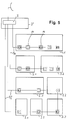
- Figure 1 is an antenna signal distribution system for Reception of television and / or radio programs shown.
- the programs are received by an antenna 5 and in a central control unit 7 where it is directed to a or several coaxial cable runs 9 are distributed.
- lines 9a to 9d are laid, to different floors 1 to 4 and / or rooms 1.1 to 4.1.
- Address blocks 21 equipped so that they are from the headquarters 7 'with the central control unit 7 by means of a communication unit placed there clearly can be identified and addressed. The address the can can already be changed by the manufacturer set or by the installer after installing the Plant can be awarded. As address block 21 are both mechanical as well as electronic components.
- Distribution system sections that are not required are in the system described can be switched off in an elegant way, which makes the Interference emission of the network can be reduced.
- control center 7 address blocks 21 and switching elements 23 necessary data exchange takes place via the coaxial connection cable 9 in one for the transmission of television and radio programs unused frequency range instead.
- FIG. 2 shows schematically the structure of a junction box 11, 11 '.
- the antenna signal is via an incoming Coaxial cable 19 ', i.e. via the inner conductor 19a 'in the Antenna socket 11, 11 'directed and there for example via a circuit board to one or more Subscriber interfaces 18 and to a further one Coaxial cable 19 "distributed.
- the address block 21 and the switching element 23 - for example bistable that can be operated via a DC voltage High frequency relay - arranged so that over the coaxial cable 19 'communication between headquarters and the Components 21 and 23 is possible.
- a switching command sent from the control center 7 can the conductor section 24 'separated in the switching element 23 and the conductor section 24 "in a branch line 19c can be closed, creating the connection to the leading Cable 19 "interrupted and between the inner conductor 19a 'and outer conductor 19b' of the leading wiring harness 19 'a terminating resistor 25 via an intermediate line 26, e.g. switched in the form of a housing cable which corresponds to the characteristic impedance of the coaxial line.
- This switching process is reversible so that a End box is convertible back into a through box.
- an address module 21 and a switching element 23 are provided in the antenna socket 11, 11 'shown in Figure 2 .
- Address blocks 21 and switching elements 23 are placed, in order to target user interfaces from the head office or To be able to switch function groups on or off.
- FIG 3 is a house distribution system with a modular structure Junction boxes 11, 11 'shown where the user has the option of customizing function blocks 14 to set or exchange accordingly. of course is also each function module with a unique address and equipped with a switching element and thus by can be switched on and off from the control center.
- the control center 7 is able to execute the switching commands To locate Receiver 29 and get exactly the ones you want Send program data.
- An intelligent control center can recognize whether an inadmissible Function module configuration was inserted or whether an extension with new function blocks 14 to errors leads.
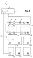
- FIG. 4 there is a house distribution system reproduced at the parallel to the coaxial Cable harnesses 9a to 9d for program transmission still additional data cables 10a to 10d are laid. At a Such system, it is possible to 10a to this data cable 10d for the communication between control center 7, address blocks 21 and switching elements 23 necessary data transmissions to use.
Landscapes
- Engineering & Computer Science (AREA)
- Signal Processing (AREA)
- Multimedia (AREA)
- Details Of Television Systems (AREA)
- Variable-Direction Aerials And Aerial Arrays (AREA)
- Small-Scale Networks (AREA)
- Two-Way Televisions, Distribution Of Moving Picture Or The Like (AREA)
Abstract
Description
Die Erfindung betrifft ein Antennensignal-Hausverteilnetz,
insbesondere ein Hausverteilnetz für die Übertragung von
Fernseh- und/oder Rundfunkprogrammen nach dem Oberbegriff
des Anspruches 1 bzw. eine zugehörige Anschlussdose nach
Anspruch 17.The invention relates to an antenna signal distribution network,
in particular a home distribution network for the transmission of
TV and / or radio programs according to the generic term
of
Hausverteileranlagen zum Empfang von Fernseh- oder Rundfunkprogrammen sind hinlänglich bekannt. So werden beispielsweise durch eine Satellitenantenne die unterschiedlichsten Fernseh- oder Rundfunkprogramme empfangen und in ein Hausverteilnetz eingespeist. Das Antennensignal wird über ein oder mehrere koaxiale Verteilkabel zu Antennensteckdosen geleitet, von denen es die angeschlossenen Teilnehmer abgreifen können. Je nach Bedarf sind im Netz Aufbereitungsanlagen, Umschaltmatrizen, Verteiler, Abzweiger oder Verstärker angeordnet. Zusätzlich kann man terrestrisch ausgestrahlte Programme über weitere Antennen empfangen und in das Verteilnetz einspeisen.Distribution boards for the reception of television or radio programs are well known. For example through a satellite antenna TV or radio programs received and in fed a house distribution network. The antenna signal will via one or more coaxial distribution cables to antenna sockets headed from which it is connected Can tap participants. According to the needs are in the network Processing plants, switching matrices, distributors, taps or amplifier arranged. In addition you can terrestrial programs via additional antennas received and fed into the distribution network.
Alternativ oder ergänzend ist es auch möglich, dass die entsprechenden Daten und Programme über ein externes Kabelnetz mit nachgeschaltetem Hausübergabepunkt bereitgestellt werden.Alternatively or in addition, it is also possible that the corresponding data and programs via an external cable network provided with a downstream house transfer point become.
Aus der EP 0 865 119 A2 ist ein entsprechend umfassenderes Verteilnetz bekannt, welches ebenfalls eine oder mehrere von einer Zentrale ausgehende Leitungen umfasst, in der jeweils eine oder mehrere in Serie geschaltete Anschlussdosen vorgesehen sind. An den Anschlussdosen können dann eine oder mehrere von außen zugängliche Anschlusselemente ausgebildet sein, um es hier einem Teilnehmer zu ermöglichen, einen oder mehrere der bereitgestellten Dienste empfangen oder nutzen zu können. Dies kann gleichermaßen auch für entsprechende Rückleitungen gelten.EP 0 865 119 A2 describes a correspondingly more comprehensive one Distribution network known, which also one or more lines originating from a control center in which one or more junction boxes connected in series are provided. Then at the junction boxes one or more connection elements accessible from the outside be trained to enable a participant here one or more of the services provided to receive or use. This can be done equally also apply to corresponding return lines.
Obgleich der Grundaufbau derartiger Hausverteileranlagen bekannt ist, treten in der Praxis und im Betrieb derartiger Anlagen gleichwohl zahlreiche Probleme auf.Although the basic structure of such home distribution systems is known occur in practice and in the operation of such However, there are numerous problems with plants.
Aufwendig sind Änderungen am Netz, da jeder koaxiale Verteilstrang durch spezielle Antennensteckdosen oder Geräte wellenwiderstandsgerecht abgeschlossen werden muss. So ist es bei einer späteren Verlängerung oder Ausweitung eines Stranges notwendig, den Abschlusswiderstand neu zu positionieren.Changes to the network are complex because each coaxial distribution line through special antenna sockets or devices must be completed in accordance with the wave resistance. So is it at a later extension or expansion of a Stranges necessary to reposition the terminating resistor.
Anlagen mit modularen Funktionsbausteinen bereiten Schwierigkeiten, insbesondere wenn mehrere Anschlussdosen in Reihe geschalten sind, weil keine Möglichkeit besteht, dem Nutzer oder Installateur unzulässige Anordnungen von Anschlussdosen oder Funktionsmodulen anzuzeigen. Ein weiterer Nachteil bekannter Verteilanlagen besteht darin, dass nicht genutzte Teilnehmerausgänge elektromagnetische Energie abstrahlen, wenn sie nicht durch Abschirmkappen verschlossen werden. Die Anlagendichtigkeit ist somit von der Sorgfalt der Teilnehmer abhängig und kann vom Anlagenbetreiber nicht beeinflusst werden.Systems with modular function blocks cause difficulties especially if several junction boxes are in Are connected in series because there is no way to User or installer prohibited arrangements of junction boxes or display functional modules. Another The disadvantage of known distribution systems is that unused subscriber outputs electromagnetic energy radiate if they are not closed by shielding caps become. The system tightness is therefore of Care of the participants depends on the system operator not be influenced.
Schließlich ist es in vielen Fällen zum anderen auch wünschenswert, einen Überblick zu bewahren, an welchen Anschlussdosen welche Teilnehmer zum Empfang welcher Dienste oder zur Einspeisung von Rückinformationen zugeschaltet sind bzw. zugeschaltet sein sollen oder dürfen.After all, in many cases it is also desirable to keep an overview of which sockets which participants receive which services or switched in for feeding in feedback information are or should be or may be switched on.
Die Aufgabe der vorliegenden Erfindung ist es von daher, ausgehend von dem gattungsbildenden Stand der Technik ein verbessertes Antennensignal-Hausverteilnetz mit verbesserten Anschlussdosen zu schaffen, dessen Aufbau, Ausbau, Wartung und Betrieb einfacher als bisher ist.The object of the present invention is therefore starting from the generic state of the art improved antenna signal home distribution network with improved To create junction boxes, its construction, expansion, Maintenance and operation is easier than before.
Die Aufgabe wird erfindungsgemäß bezüglich des Verteilnetzes
entsprechend den im Anspruch 1, 2 und/oder 3 angegebenen
Merkmalen und bezüglich der Anschlussdose gemäß Anspruch
18 gelöst. Vorteilhafte Ausgestaltungen der Erfindung
sind in den Unteransprüchen angegeben.The object is achieved according to the distribution network
corresponding to those specified in
Eine deutliche Verbesserung gegenüber herkömmlichen Lösungen wird in dem erfindungsgemäßen Verteilnetz dadurch erzielt, dass die Anschlussdosen in dem Verteilnetz mit elektrischen und/oder mechanischen Adressbausteinen so ausgerüstet sind, dass alle Anschlussdosen im Verteilnetz von einer Steuerungseinheit oder Zentrale aus eindeutig identifizierbar sind.A significant improvement over conventional solutions is thereby in the distribution network according to the invention achieved that the junction boxes in the distribution network electrical and / or mechanical address blocks so are equipped that all junction boxes in the distribution network clearly from a control unit or control center are identifiable.
In einer bevorzugten Ausführungsform der Erfindung kann nicht nur das Erkennungssignal bzw. die Adresse jeder Antennensteckdose von der zentralen Steuereinheit aus erfasst und/oder abgefragt werden, sondern ggf. auch verändert und damit eingestellt werden.In a preferred embodiment of the invention not just the detection signal or the address of everyone Antenna socket from the central control unit recorded and / or queried, but also changed if necessary and thus be set.
Abgesehen davon, dass die Adressierung der einzelnen Anschlussdosen elektrisch und/oder mechanisch erfolgen kann, ist es ebenso möglich, dass beispielsweise die Anschlussdosen bereits herstellerseitig mit einem Adressbaustein ausgestattet werden, der einen eindeutigen Identifikationscode sendet, wobei der Identifikationscode nicht mehr veränderbar und/oder einstellbar, wohl aber lesbar ist.Apart from that the addressing of the individual junction boxes can be done electrically and / or mechanically, it is also possible that, for example, the junction boxes already with an address module from the manufacturer be equipped with a unique identification code sends, the identification code no longer changeable and / or adjustable, but is legible.
Alternativ oder ergänzend hat es sich als besonders günstig erwiesen, wenn die Anschlussdosen zusätzlich mit einem von der Zentrale aus durch den Adressbaustein eindeutig ansteuerbaren Schaltelement ausgerüstet werden, das den HF-Signalfluss unterbrechen kann, insbesondere wenn das Schaltelement zugleich den Koaxialleitungsstrang wellenwiderstandsgerecht abschließt.Alternatively or in addition, it has proven to be particularly favorable proven if the junction boxes are additionally equipped with a from the control center through the address module controllable switching element that the RF signal flow can interrupt, especially if that Switching element at the same time the coaxial cable harness suitable for shaft resistance completes.
Der bei den beschriebenen Varianten für das Identifizieren einer Dose notwendige Datenaustausch zwischen Zentrale und dem Adressbaustein sowie die Schaltsignalübertragung erfolgen über die koaxialen Verteilkabel, jedoch in einem Frequenzbereich, der die Übertragung der Fernseh- und Rundfunkprogramme nicht beeinträchtigt.The one for the described variants for identification data exchange between head office and the address block and the switching signal transmission over the coaxial distribution cables, but in one Frequency range that the transmission of television and Broadcast programs not affected.
Bei Antennensignal-Hausverteilanlagen mit solchen Antennensteckdosen kann auf einfache Weise ein koaxialer Verteilstrang verlängert oder verkürzt werden, indem von der Zentrale aus in der ursprünglich letzten und in der neuen letzten Dose des Stranges das Schaltelement betätigt wird.In antenna signal distribution systems with such antenna sockets can easily be a coaxial distribution line be extended or shortened by the Head office out in the original last one and in the new one last can of the strand the switching element is actuated.
Ein derartiges technisches Merkmal erlaubt es auch, nicht benötigte Teilnehmerschnittstellen und Leitungsstränge von der Zentrale aus abzukoppeln und so die Schirmdichtigkeit einer Verteilanlage zu erhöhen.Such a technical feature also does not allow it required user interfaces and wiring harnesses from decoupling from the control center and thus the shield tightness to increase a distribution system.
Vorteile ergeben sich in Anlagen mit eindeutig identifizierbaren Antennensteckdosen, wenn eine Gebührenabrechnung erfolgen soll. Es ist in der Zentrale genau feststellbar, wann und welche Programme oder multimedialen Dienste über eine Anschlussdose von einem Teilnehmer empfangen worden sind. Sind Adressbausteine und Schaltelemente den Teilnehmerausgängen zugeordnet, sind unpünktliche Zahler von der Zentrale aus und somit ohne Betreten der Wohneinheiten ohne großen Aufwand vom Netz trennbar.There are advantages in systems with clearly identifiable ones Antenna sockets when billing should be done. It can be determined exactly at the headquarters when and what programs or multimedia services about a junction box has been received by a subscriber are. Are address blocks and switching elements of the subscriber outputs assigned unpunctual payers of the Central from and thus without entering the residential units Can be disconnected from the network with little effort.
Die erfindungsgemäße Verteilanlage ermöglicht letztlich insbesondere auch unter Zuschaltung eines Mikroprozessors in der Zentraleinheit, dass von dieser Steuerungseinheit oder Zentrale aus eine Kommunikation mit allen und insbesondere mit den in Reihe geschalteten Anschlussdosen sowie zwischen Anschlussdosen möglich ist.The distribution system according to the invention ultimately enables especially with the addition of a microprocessor in the central processing unit that from this control unit or headquarters from communicating with everyone and in particular with the junction boxes connected in series as well as between junction boxes.
Zudem sind von der Zentral- oder Steuerungseinheit aus die unterschiedlichsten Abfragen realisierbar, wodurch Fehler erkannt und angezeigt werden können, etwa dann, wenn der Signalpegel im Verteilnetz oder in einer bestimmten Leitung zu niedrig ist bzw. zu stark abgefallen ist. In einem solchen Fall ist eine automatische Pegelanpassung durchführbar.In addition, from the central or control unit A wide variety of queries can be implemented, which leads to errors can be recognized and displayed, for example when the Signal level in the distribution network or in a specific line is too low or has dropped too much. In one In this case, automatic level adjustment can be carried out.
Ebenso sind Installationsfehler bei der Überprüfung und Abnahme einer Verteilanlage schnell und eindeutig lokalisierbar.There are also installation errors when checking and Acceptance of a distribution system can be localized quickly and clearly.
Schließlich ist eine intelligente zentrale Steuereinheit in der Lage, zu erkennen, ob bei modularen Anlagen in einen Leitungsstrang eine unzulässige Funktionsmodulkonfiguration gesteckt worden ist. Bei einem erfindungsgemäßen Hausverteilnetz kann von der Zentrale oder Steuerungseinheit aus nach einer Analyse der bereits angeschlossenen Dosen und/oder Funktionsmodule sowie der Verbindungskabellängen dem Nutzer mitgeteilt werden, ob das Einfügen eines zusätzlichen Moduls bzw. einer neuen Anschlussdose noch möglich ist oder ob der Signalpegel für einen derartigen Fall nicht ausreicht.After all, is an intelligent central control unit able to recognize whether in modular systems in a wiring harness an impermissible function module configuration has been inserted. In an inventive Home distribution network can be from the central office or control unit off after an analysis of the already connected Sockets and / or functional modules as well as the connecting cable lengths be informed to the user whether the insertion of a additional module or a new junction box is possible or whether the signal level for such Case not enough.
Schließlich gestattet es ein derartiges Netz aber auch, problemlos Zugriffsrechte unterschiedlich zu verteilen, zu ändern und/oder zu vergeben bzw. Programmpakete nur an bestimmte Dosen zu leiten.Finally, such a network also allows easily distribute access rights differently, too change and / or to assign or program packages only to to deliver certain doses.
Durch die erwähnte Abschaltung von nicht benötigten Anschlussdosen, beispielsweise mittels eines bistabilen HF-Relais oder eines anderen geeigneten elektronischen oder elektrischen Schalters, ergibt sich insbesondere in Hotels, Krankenhäusern, Bürohäusern etc. die Möglichkeit, für die gesamte Anlage eine deutlich verbesserte Abschirmung zu realisieren. Dabei kann das Ab- oder Zuschalten von Antennensteckdosen oder Teilnehmerschnittstellen im gesamten Haus, in bestimmten Etagen, in bestimmten Zimmern oder nur einzeln erfolgen und beispielsweise von der Zentrale aus durch eine Zeitschaltuhr gesteuert werden. Schließlich ermöglicht dies auch, in einem Haus eine "Kindersicherung" zu verwirklichen, um beispielsweise in Kinderzimmern eine Anschlussdose in bestimmten Zeiten und/oder nur mit bestimmten Diensten zuzuschalten.Due to the mentioned switching off of unneeded sockets, for example by means of a bistable HF relay or another suitable electronic or electrical switch, especially in hotels, Hospitals, office buildings etc. the possibility a significantly improved shielding for the entire system to realize. It can be switched off or on of antenna sockets or subscriber interfaces in entire house, on certain floors, in certain rooms or only individually and for example by the Central can be controlled by a timer. Finally, this also enables "child protection" in a house. to realize, for example, in children's rooms a junction box at certain times and / or only connect with certain services.
Eine erfindungsgemäße Anlage gestattet auch die Reihenschaltung mehrerer Receiver, da im Gegensatz zu herkömmlichen Netzen der Ursprung der Receiverschaltsignale lokalisierbar ist und genau dorthin die gewünschten Daten gesendet werden können.A system according to the invention also permits series connection several receivers, as opposed to conventional ones Networks the origin of the receiver switching signals can be localized is and exactly there the desired data can be sent.
Zusammenfassend lässt sich allgemein festhalten, dass die erfindungsgemäße Antennensignal-Hausverteilanlage die schnelle Inventarisierung und Kompatibilitätsprüfung aller Netzkomponenten gestattet, die einfache Archivierung bzw. Dokumentation der Anlagenstruktur erlaubt sowie eine bequeme Erweiterung bzw. Veränderung der Verteilstränge zulässt.In summary, it can generally be said that the antenna signal home distribution system according to the invention quick inventory and compatibility check of all Network components allow simple archiving or Documentation of the system structure allowed as well as a convenient Extension or change of the distribution lines allows.
Die Erfindung wird nachfolgend anhand mehrerer Ausführungsbeispiele erläutert. Dabei zeigen im einzelnen
- Figur 1 :
- eine schematische Darstellung einer Antennensignal-Hausverteilanlage zum Empfang von Fernseh- und/oder Rundfunkprogrammen;
- Figur 2 :
- eine schematische Querschnittsdarstellung durch eine Anschlussdose zur Erläuterung des prinzipiellen Aufbaus;
- Figur 3 :
- ein zu
Figur 1 abgewandeltes Ausführungsbeispiel mit modular aufgebauten Anschlussdosen; - Figur 4 :
- ein zu
Figur 1 abgewandeltes Ausführüngsbeispiel mit zum koaxialen Programmübertragungskabel parallel verlegtem Datenkabel; - Figur 5 :
- ein zu
Figur 1 abgewandeltes Ausführungsbeispiel mit ringförmigen Leitungssträngen; und - Figur 6 :
- ein zu Figur 5 abgewandeltes Ausführungsbeispiel mit vernetzten Leitungssträngen.
- Figure 1:
- a schematic representation of an antenna signal house distribution system for receiving television and / or radio programs;
- Figure 2:
- a schematic cross-sectional view through a junction box to explain the basic structure;
- Figure 3:
- an embodiment modified to Figure 1 with modular junction boxes;
- Figure 4:
- a modified example of Figure 1 with data cable laid parallel to the coaxial program transmission cable;
- Figure 5:
- an embodiment modified to Figure 1 with annular wiring harnesses; and
- Figure 6:
- an embodiment modified to Figure 5 with networked wiring harnesses.
In Figur 1 ist eine Antennensignal-Hausverteilanlage zum Empfang von Fernseh- und/oder Rundfunkprogrammen gezeigt.In Figure 1 is an antenna signal distribution system for Reception of television and / or radio programs shown.
Die Programme werden von einer Antenne 5 empfangen und in
eine zentrale Steuereinheit 7 geleitet, wo sie auf einen
oder mehrere koaxiale Leitungsstränge 9 verteilt werden.The programs are received by an antenna 5 and in
a
Im Ausführungsbeispiel sind vier Leitungen 9a bis 9d verlegt,
die zu unterschiedlichen Stockwerken 1 bis 4
und/oder Zimmern 1.1 bis 4.1 führen.In the exemplary embodiment, four lines 9a to 9d are laid,
to
In jeder der Leitungen 9a bis 9d sind mehrere Anschlussdosen vorgesehen, wobei in den ersten Dosen 11 eines Stranges das HF-Signal durchgeschleift und in der letzten Dose 11' eines Stranges die Koaxialleitung wellenwiderstandsgerecht abgeschlossen wird. Ebenso sind Leitungsstränge mit nur einer Enddose 11' realisierbar.There are several junction boxes in each of the lines 9a to 9d provided, in the first doses 11 a The RF signal is looped through and in the last Box 11 'of a strand, the coaxial line suitable for the wave resistance is completed. There are also wiring harnesses realizable with only one outlet 11 '.
Zumindest ein Teil der Anschlussdosen 11, 11' besitzt
Teilnehmerschnittstellen 12, von denen der Nutzer das
Antennensignal abgreifen kann.Has at least part of the
Alle Anschlussdosen 11, 11' des Verteilnetzes sind mit
Adressbausteinen 21 so ausgerüstet, dass sie von der Zentrale
7' mit der zentralen Steuereinheit 7 aus mittels
einer dort plazierten Kommunikationseinheit eindeutig
identifiziert und angesprochen werden können. Die Adresse
der Dose kann bereits herstellerseitig unveränderlich
eingestellt oder vom Monteur nach der Installation der
Anlage vergeben werden. Als Adressbaustein 21 sind sowohl
mechanische als auch elektronische Bauelemente geeignet.All
In die Dosen 11, 11' sind zusätzlich Schaltelemente 23
integriert, mit denen von der Zentrale aus der HF-Signalfluss
unterbrochen oder wieder hergestellt und der weiterführende
Leitungsstrang wellenwiderstandsgerecht abgeschlossen
werden kann.In the
Dadurch ist es möglich, nach Installation der Anlage von
der Zentrale 7 aus einen Leitungsstrang durch Betätigen
des Schalters 23 in der letzten Dose 11' verlustfrei abzuschließen.
Ebenso sind Leitungsstränge einfach erweiterbar.
Hierzu müssen nur in der bisherigen letzten Dose 11'
und in der neuen letzten Dose des Stranges die Schaltelemente
betätigt werden.This makes it possible to install the system from
the
In der beschriebenen Anlage sind nicht benötigte Verteilnetzabschnitte auf elegante Weise abschaltbar, wodurch die Störstrahlaussendung des Netzes reduzierbar ist.Distribution system sections that are not required are in the system described can be switched off in an elegant way, which makes the Interference emission of the network can be reduced.
Der für die Kommunikation zwischen Zentrale 7, Adressbausteinen
21 und Schaltelementen 23 notwendige Datenaustausch
findet über das koaxiale Verbindungskabel 9 in
einem für die Übertragung der Fernseh- und Rundfunkprogramme
nicht genutzten Frequenzbereich statt.The one for communication between
Figur 2 zeigt schematisch den Aufbau einer Anschlussdose
11, 11'. Das Antennensignal wird über ein ankommendes
Koaxialkabel 19', d.h. über den Innenleiter 19a' in die
Antennensteckdose 11, 11' geleitet und dort beispielsweise
über eine Leiterplattenschaltung an eine oder mehrere
Teilnehmerschnittstellen 18 und an ein weiterführendes
Koaxialkabel 19" verteilt. Im Signalweg sind der Adressbaustein
21 und das Schaltelement 23 - beispielsweise ein
über eine Gleichspannung bedienbares bistabiles
Hochfrequenz-Relais - angeordnet, so dass über das Koaxialkabel
19' eine Kommunikation zwischen Zentrale und den
Bauteilen 21 und 23 möglich ist.Figure 2 shows schematically the structure of a
Durch einen von der Zentrale 7 gesendeten Schaltbefehl
kann im Schaltelement 23 der Leiterabschnitt 24' aufgetrennt
und der Leiterabschnitt 24" in einer Zweigleitung
19c geschlossen werden, wodurch die Verbindung zum wegführenden
Kabel 19" unterbrochen und zwischen Innenleiter
19a' und Außenleiter 19b' des hinführenden Leitungsstranges
19' ein Abschlusswiderstand 25 über eine Zwischenleitung
26, z.B. in Form einer Gehäuseleitung geschalten
wird, der dem Wellenwiderstand der Koaxialleitung entspricht.
Dieser Schaltvorgang ist umkehrbar, damit eine
Abschlussdose wieder in eine Durchgangsdose wandelbar ist.By a switching command sent from the
In der in Figur 2 dargestellten Antennensteckdose 11, 11'
sind ein Adressbaustein 21 und ein Schaltelement 23 vorgesehen.
Genauso können für die Teilnehmeranschlüsse 18
oder bestimmte Funktionsgruppen auf der Leiterplatte
Adressbausteine 21 und Schaltelemente 23 plaziert werden,
um von der Zentrale gezielt Teilnehmerschnittstellen oder
Funktionsgruppen ab- oder zuschalten zu können.In the
In Figur 3 ist eine Hausverteilanlage mit modular aufgebauten
Anschlussdosen 11, 11' abgebildet, wo der Nutzer
die Möglichkeit hat, Funktionsbausteine 14 seinen Wünschen
entsprechend zu setzen oder auszutauschen. Natürlich ist
auch jedes Funktionsmodul mit einer eindeutigen Adresse
und einem Schaltelement versehen ausstattbar und somit von
der Zentrale aus ab- und zuschaltbar.In Figure 3 is a house distribution system with a modular
Durch die eindeutige Identifizierbarkeit einer Anschlussdose
11, 11', eines Funktionsmoduls 14 oder einer Teilnehmerschnittstelle
12 im Netz ist es zudem möglich, mehrere
Receiver 29 in einem Leitungsstrang in Reihe zu schalten.
Die Zentrale 7 ist in der Lage, die Schaltbefehle der
Receiver 29 zu lokalisieren und genau dorthin die gewünschten
Programmdaten senden.Due to the clear identifiability of a
Eine intelligente Zentrale kann erkennen, ob eine unzulässige Funktionsmodulkonfiguration gesteckt wurde bzw. ob eine Erweiterung mit neuen Funktionsbausteinen 14 zu Fehlern führt.An intelligent control center can recognize whether an inadmissible Function module configuration was inserted or whether an extension with new function blocks 14 to errors leads.
Im Ausführungsbeispiel nach Figur 4 ist eine Hausverteilanlage
wiedergegeben, bei der parallel zu den koaxialen
Kabelsträngen 9a bis 9d für die Programmübertragung noch
zusätzliche Datenkabel 10a bis 10d verlegt sind. Bei einer
derartigen Anlage ist es möglich, diese Datenkabel 10a bis
10d für die zur Kommunikation zwischen Zentrale 7, Adressbausteinen
21 und Schaltelementen 23 notwendigen Datenübertragungen
zu nutzen.In the exemplary embodiment according to FIG. 4 there is a house distribution system
reproduced at the parallel to the coaxial
Cable harnesses 9a to 9d for program transmission still
In Figur 5 ist eine Anlage aufgezeigt, in der die koaxialen
Leitungsstränge 9e und 9f in der Zentrale beginnen und
enden, also ringförmig aufgebaut sind. Der Installateur
kann eine Ringleitung von der Zentrale durch Betätigen von
Schaltelementen auftrennen und dadurch zwei separate, in
der Zentrale 7 beginnende Leitungsstränge aufbauen, deren
Länge je nach Bedarf später veränderbar ist.In Figure 5, a system is shown in which the
Bei der Ausführungsvariante nach Figur 6 sind gegenüber dem vorhergehenden Beispiel zusätzliche Leitungen zwischen den Zimmern 4.1 und 3.1 sowie 3.1 und 2.1 verlegt. Durch eine derartige Netzstruktur ist ein Haus universell verkabelbar.In the embodiment variant according to FIG. 6 are opposite the previous example additional lines between rooms 4.1 and 3.1 as well as 3.1 and 2.1. By Such a network structure is universally wirable to a house.
Ordnet man jeder weiterführenden Leitung 19" einer Anschlussdose
11" einen Adressbaustein 21 und ein Schaltelement
23 zu, besitzen der Monteur oder eine intelligente
Zentrale eine große Flexibilität, durch Betätigen der
Schaltelemente, beispielsweise bei zu niedrigem Signalpegel
oder bei Änderung der Nutzungsstruktur des Gebäudes,
den Erfordernissen entsprechende Leitungsstränge zu konfigurieren
bzw. abzuändern.If you assign each
Claims (18)
Applications Claiming Priority (2)
| Application Number | Priority Date | Filing Date | Title |
|---|---|---|---|
| DE10005763A DE10005763B4 (en) | 2000-02-10 | 2000-02-10 | Antenna signal home distribution network for the transmission of television and / or radio programs |
| DE10005763 | 2000-02-10 |
Publications (3)
| Publication Number | Publication Date |
|---|---|
| EP1124292A2 true EP1124292A2 (en) | 2001-08-16 |
| EP1124292A3 EP1124292A3 (en) | 2003-08-06 |
| EP1124292B1 EP1124292B1 (en) | 2006-06-21 |
Family
ID=7630372
Family Applications (1)
| Application Number | Title | Priority Date | Filing Date |
|---|---|---|---|
| EP01103004A Expired - Lifetime EP1124292B1 (en) | 2000-02-10 | 2001-02-08 | Home distribution apparatus for antenna signals for transmission of television and/or radio programs |
Country Status (3)
| Country | Link |
|---|---|
| EP (1) | EP1124292B1 (en) |
| AT (1) | ATE331322T1 (en) |
| DE (2) | DE10005763B4 (en) |
Cited By (1)
| Publication number | Priority date | Publication date | Assignee | Title |
|---|---|---|---|---|
| EP2717198A1 (en) | 2012-10-04 | 2014-04-09 | Kathrein Werke KG | Multimedia or antenna socket |
Families Citing this family (3)
| Publication number | Priority date | Publication date | Assignee | Title |
|---|---|---|---|---|
| DE102005036810B4 (en) | 2005-08-04 | 2007-09-06 | Kathrein-Werke Kg | HF socket |
| DE102008029417A1 (en) * | 2008-06-23 | 2009-12-24 | Jultec Technology Gmbh | Configurable antenna socket for use in satellite reception systems with subscriber controlled frequency converters |
| DE102009026358A1 (en) | 2009-08-10 | 2011-02-17 | Rotek Microelectronic Gmbh & Co. Kg | Converter for converting control data in house distribution system that distributes TV and radio signals, has communication interfaces provided for bidirectional data transmission of portion of read control data over output |
Citations (6)
| Publication number | Priority date | Publication date | Assignee | Title |
|---|---|---|---|---|
| US4461032A (en) * | 1982-06-21 | 1984-07-17 | Zenith Radio Corporation | CATV Service controller |
| DE3727864C1 (en) * | 1987-08-20 | 1988-12-29 | Robert Neuberger | Enabling socket for providing authorised receivers with selected television programmes |
| DE3727865C1 (en) * | 1987-08-20 | 1988-12-29 | Robert Neuberger | Enabling socket for providing authorised receivers with selected television programmes |
| EP0371401A1 (en) * | 1988-11-29 | 1990-06-06 | Neuberger Nachrichten- Und Antennentechnik Gmbh | Remotely addressable star distributor for television signals |
| WO1998005163A1 (en) * | 1996-07-26 | 1998-02-05 | Klein, Patrick | Decentralized subscriber access system |
| EP0865119A2 (en) * | 1997-03-11 | 1998-09-16 | Siemens Aktiengesellschaft | Junction box for a distribution system |
Family Cites Families (1)
| Publication number | Priority date | Publication date | Assignee | Title |
|---|---|---|---|---|
| DE19633076A1 (en) * | 1996-08-16 | 1998-02-19 | Pansat Gmbh Communications Ele | Decentralised subscriber access system for broadband networks |
-
2000
- 2000-02-10 DE DE10005763A patent/DE10005763B4/en not_active Expired - Fee Related
-
2001
- 2001-02-08 DE DE50110194T patent/DE50110194D1/en not_active Expired - Lifetime
- 2001-02-08 EP EP01103004A patent/EP1124292B1/en not_active Expired - Lifetime
- 2001-02-08 AT AT01103004T patent/ATE331322T1/en active
Patent Citations (6)
| Publication number | Priority date | Publication date | Assignee | Title |
|---|---|---|---|---|
| US4461032A (en) * | 1982-06-21 | 1984-07-17 | Zenith Radio Corporation | CATV Service controller |
| DE3727864C1 (en) * | 1987-08-20 | 1988-12-29 | Robert Neuberger | Enabling socket for providing authorised receivers with selected television programmes |
| DE3727865C1 (en) * | 1987-08-20 | 1988-12-29 | Robert Neuberger | Enabling socket for providing authorised receivers with selected television programmes |
| EP0371401A1 (en) * | 1988-11-29 | 1990-06-06 | Neuberger Nachrichten- Und Antennentechnik Gmbh | Remotely addressable star distributor for television signals |
| WO1998005163A1 (en) * | 1996-07-26 | 1998-02-05 | Klein, Patrick | Decentralized subscriber access system |
| EP0865119A2 (en) * | 1997-03-11 | 1998-09-16 | Siemens Aktiengesellschaft | Junction box for a distribution system |
Cited By (2)
| Publication number | Priority date | Publication date | Assignee | Title |
|---|---|---|---|---|
| EP2717198A1 (en) | 2012-10-04 | 2014-04-09 | Kathrein Werke KG | Multimedia or antenna socket |
| DE102012019452A1 (en) | 2012-10-04 | 2014-04-10 | Kathrein-Werke Kg | Multimedia box |
Also Published As
| Publication number | Publication date |
|---|---|
| DE10005763B4 (en) | 2005-12-22 |
| DE50110194D1 (en) | 2006-08-03 |
| EP1124292B1 (en) | 2006-06-21 |
| EP1124292A3 (en) | 2003-08-06 |
| DE10005763A1 (en) | 2001-08-30 |
| ATE331322T1 (en) | 2006-07-15 |
Similar Documents
| Publication | Publication Date | Title |
|---|---|---|
| DE3818601A1 (en) | DIGITAL SIGNAL TRANSFER SYSTEM FOR HOUSE CONTROL TECHNOLOGY | |
| EP0346614B1 (en) | Method of initialising a digital signal transmission system | |
| EP0790541A2 (en) | Connecting arrangement for an electrical installation system | |
| DE10155481A1 (en) | Device for controlling/monitoring release of reception signals at domestic cable distribution system connection points has central control unit directly connected to connection points | |
| EP1124292A2 (en) | Home distribution apparatus for antenna signals for transmission of television and/or radio programs | |
| EP0437696B1 (en) | Remote-controlled connecting device | |
| EP0208959A1 (en) | Communication system | |
| EP1760917B1 (en) | Method and apparatus for the configuration of n independent users of a satellite receiving installation | |
| EP0225461B1 (en) | Home signal distributing apparatus | |
| DE3623805A1 (en) | Signal transmission system for remotely controlling and monitoring electrical or electronic devices | |
| DE19610381C2 (en) | Installation bus system for a track lighting | |
| DE69924285T3 (en) | METHOD FOR DISTRIBUTING AND TRANSMITTING COMMUNICATION AND MULTIMEDIA SIGNALS AND SIGNAL DISTRIBUTION APPARATUS FOR TRANSMITTING THE COMMUNICATION AND MULTIMEDIA SIGNALS | |
| EP1099991B1 (en) | Method for configuring elevator controllers | |
| EP0914742B1 (en) | Decentralized subscriber access system | |
| DE10064370C1 (en) | Multiswitch head unit, satellite receiving system and method for installing a satellite receiving system | |
| EP1076376A2 (en) | Expansion set in the form of a separated antenna base for a receiving apparatus, in particular a digital video broadcasting-terrestrial receiver (DVB-T) | |
| WO2002041582A1 (en) | Coupling device and coupling method for coupling of local and global networks | |
| AT405998B (en) | EIB DEVICE FOR INSTALLATION IN AN INSTALLATION BOX | |
| EP1005228B1 (en) | Circuit for the transmission of signals received analog and/or digital | |
| EP0371401A1 (en) | Remotely addressable star distributor for television signals | |
| DE202007017590U1 (en) | Switches with subscriber-controlled converters for satellite receiving systems with automatic mode switching | |
| DE10103521C1 (en) | control system | |
| EP0059786A2 (en) | Antenna socket | |
| DE4221456A1 (en) | Central operating device for electrical loads - has address selection circuit between operating device and each controlled load in building | |
| DE4207306C2 (en) | Reception system for satellite television programs |
Legal Events
| Date | Code | Title | Description |
|---|---|---|---|
| PUAI | Public reference made under article 153(3) epc to a published international application that has entered the european phase |
Free format text: ORIGINAL CODE: 0009012 |
|
| AK | Designated contracting states |
Kind code of ref document: A2 Designated state(s): AT BE CH CY DE DK ES FI FR GB GR IE IT LI LU MC NL PT SE TR |
|
| AX | Request for extension of the european patent |
Free format text: AL;LT;LV;MK;RO;SI |
|
| PUAL | Search report despatched |
Free format text: ORIGINAL CODE: 0009013 |
|
| AK | Designated contracting states |
Designated state(s): AT BE CH CY DE DK ES FI FR GB GR IE IT LI LU MC NL PT SE TR |
|
| AX | Request for extension of the european patent |
Extension state: AL LT LV MK RO SI |
|
| RIC1 | Information provided on ipc code assigned before grant |
Ipc: 7H 04H 1/04 B Ipc: 7H 01R 13/646 A Ipc: 7H 04N 7/10 B Ipc: 7H 04H 1/02 B |
|
| 17P | Request for examination filed |
Effective date: 20031007 |
|
| AKX | Designation fees paid |
Designated state(s): AT BE DE NL |
|
| 17Q | First examination report despatched |
Effective date: 20040330 |
|
| GRAP | Despatch of communication of intention to grant a patent |
Free format text: ORIGINAL CODE: EPIDOSNIGR1 |
|
| GRAS | Grant fee paid |
Free format text: ORIGINAL CODE: EPIDOSNIGR3 |
|
| GRAA | (expected) grant |
Free format text: ORIGINAL CODE: 0009210 |
|
| AK | Designated contracting states |
Kind code of ref document: B1 Designated state(s): AT BE DE NL |
|
| REF | Corresponds to: |
Ref document number: 50110194 Country of ref document: DE Date of ref document: 20060803 Kind code of ref document: P |
|
| PLBE | No opposition filed within time limit |
Free format text: ORIGINAL CODE: 0009261 |
|
| STAA | Information on the status of an ep patent application or granted ep patent |
Free format text: STATUS: NO OPPOSITION FILED WITHIN TIME LIMIT |
|
| 26N | No opposition filed |
Effective date: 20070322 |
|
| PGFP | Annual fee paid to national office [announced via postgrant information from national office to epo] |
Ref country code: NL Payment date: 20140220 Year of fee payment: 14 |
|
| PGFP | Annual fee paid to national office [announced via postgrant information from national office to epo] |
Ref country code: BE Payment date: 20140219 Year of fee payment: 14 |
|
| PG25 | Lapsed in a contracting state [announced via postgrant information from national office to epo] |
Ref country code: BE Free format text: LAPSE BECAUSE OF NON-PAYMENT OF DUE FEES Effective date: 20150228 |
|
| REG | Reference to a national code |
Ref country code: NL Ref legal event code: V1 Effective date: 20150901 |
|
| PG25 | Lapsed in a contracting state [announced via postgrant information from national office to epo] |
Ref country code: NL Free format text: LAPSE BECAUSE OF NON-PAYMENT OF DUE FEES Effective date: 20150901 |
|
| PGFP | Annual fee paid to national office [announced via postgrant information from national office to epo] |
Ref country code: AT Payment date: 20160218 Year of fee payment: 16 |
|
| PGFP | Annual fee paid to national office [announced via postgrant information from national office to epo] |
Ref country code: DE Payment date: 20170222 Year of fee payment: 17 |
|
| REG | Reference to a national code |
Ref country code: AT Ref legal event code: MM01 Ref document number: 331322 Country of ref document: AT Kind code of ref document: T Effective date: 20170208 |
|
| PG25 | Lapsed in a contracting state [announced via postgrant information from national office to epo] |
Ref country code: AT Free format text: LAPSE BECAUSE OF NON-PAYMENT OF DUE FEES Effective date: 20170208 |
|
| REG | Reference to a national code |
Ref country code: DE Ref legal event code: R082 Ref document number: 50110194 Country of ref document: DE Representative=s name: FLACH BAUER STAHL PATENTANWAELTE PARTNERSCHAFT, DE |
|
| REG | Reference to a national code |
Ref country code: DE Ref legal event code: R119 Ref document number: 50110194 Country of ref document: DE |
|
| PG25 | Lapsed in a contracting state [announced via postgrant information from national office to epo] |
Ref country code: DE Free format text: LAPSE BECAUSE OF NON-PAYMENT OF DUE FEES Effective date: 20180901 |