EP1125637A2 - Fluid dispenser - Google Patents
Fluid dispenser Download PDFInfo
- Publication number
- EP1125637A2 EP1125637A2 EP01103046A EP01103046A EP1125637A2 EP 1125637 A2 EP1125637 A2 EP 1125637A2 EP 01103046 A EP01103046 A EP 01103046A EP 01103046 A EP01103046 A EP 01103046A EP 1125637 A2 EP1125637 A2 EP 1125637A2
- Authority
- EP
- European Patent Office
- Prior art keywords
- actuation
- discharge device
- housing
- lock
- release position
- Prior art date
- Legal status (The legal status is an assumption and is not a legal conclusion. Google has not performed a legal analysis and makes no representation as to the accuracy of the status listed.)
- Granted
Links
Images


Classifications
-
- A—HUMAN NECESSITIES
- A61—MEDICAL OR VETERINARY SCIENCE; HYGIENE
- A61M—DEVICES FOR INTRODUCING MEDIA INTO, OR ONTO, THE BODY; DEVICES FOR TRANSDUCING BODY MEDIA OR FOR TAKING MEDIA FROM THE BODY; DEVICES FOR PRODUCING OR ENDING SLEEP OR STUPOR
- A61M15/00—Inhalators
- A61M15/0065—Inhalators with dosage or measuring devices
- A61M15/0068—Indicating or counting the number of dispensed doses or of remaining doses
- A61M15/0081—Locking means
-
- B—PERFORMING OPERATIONS; TRANSPORTING
- B05—SPRAYING OR ATOMISING IN GENERAL; APPLYING FLUENT MATERIALS TO SURFACES, IN GENERAL
- B05B—SPRAYING APPARATUS; ATOMISING APPARATUS; NOZZLES
- B05B11/00—Single-unit hand-held apparatus in which flow of contents is produced by the muscular force of the operator at the moment of use
- B05B11/0005—Components or details
- B05B11/0027—Means for neutralising the actuation of the sprayer ; Means for preventing access to the sprayer actuation means
-
- B—PERFORMING OPERATIONS; TRANSPORTING
- B05—SPRAYING OR ATOMISING IN GENERAL; APPLYING FLUENT MATERIALS TO SURFACES, IN GENERAL
- B05B—SPRAYING APPARATUS; ATOMISING APPARATUS; NOZZLES
- B05B12/00—Arrangements for controlling delivery; Arrangements for controlling the spray area
- B05B12/02—Arrangements for controlling delivery; Arrangements for controlling the spray area for controlling time, or sequence, of delivery
-
- A—HUMAN NECESSITIES
- A61—MEDICAL OR VETERINARY SCIENCE; HYGIENE
- A61M—DEVICES FOR INTRODUCING MEDIA INTO, OR ONTO, THE BODY; DEVICES FOR TRANSDUCING BODY MEDIA OR FOR TAKING MEDIA FROM THE BODY; DEVICES FOR PRODUCING OR ENDING SLEEP OR STUPOR
- A61M2205/00—General characteristics of the apparatus
- A61M2205/50—General characteristics of the apparatus with microprocessors or computers
- A61M2205/52—General characteristics of the apparatus with microprocessors or computers with memories providing a history of measured variating parameters of apparatus or patient
-
- A—HUMAN NECESSITIES
- A61—MEDICAL OR VETERINARY SCIENCE; HYGIENE
- A61M—DEVICES FOR INTRODUCING MEDIA INTO, OR ONTO, THE BODY; DEVICES FOR TRANSDUCING BODY MEDIA OR FOR TAKING MEDIA FROM THE BODY; DEVICES FOR PRODUCING OR ENDING SLEEP OR STUPOR
- A61M2205/00—General characteristics of the apparatus
- A61M2205/82—Internal energy supply devices
- A61M2205/8206—Internal energy supply devices battery-operated
-
- B—PERFORMING OPERATIONS; TRANSPORTING
- B05—SPRAYING OR ATOMISING IN GENERAL; APPLYING FLUENT MATERIALS TO SURFACES, IN GENERAL
- B05B—SPRAYING APPARATUS; ATOMISING APPARATUS; NOZZLES
- B05B11/00—Single-unit hand-held apparatus in which flow of contents is produced by the muscular force of the operator at the moment of use
- B05B11/01—Single-unit hand-held apparatus in which flow of contents is produced by the muscular force of the operator at the moment of use characterised by the means producing the flow
- B05B11/10—Pump arrangements for transferring the contents from the container to a pump chamber by a sucking effect and forcing the contents out through the dispensing nozzle
Definitions
- the invention relates to a discharge device for media.
- Such discharge devices are used in particular for the Spraying a fluid used.
- This preferably contains Fluid one or more active pharmaceutical ingredients.
- Such discharge devices are for example from DE 198 07 921 known and have a housing on which a Actuator is arranged relatively movable.
- the The actuating element can thereby move the path of an actuating stroke corresponding path with respect to the housing.
- a control unit is provided, which at least the Time recorded since the last actuation of the actuating element. Furthermore, one is controlled by the control unit actuatable actuation lock provided, the actuation lock in its locked position performing a Actuating stroke blocks and in its release position Carries out an actuation stroke releases.
- Such discharge devices are used when to avoid excessive drug concentration of the medium to be discharged should. This is particularly the case, for example, if the medium to be dispensed is an active pharmaceutical ingredient or contains an active ingredient combination and from the patient self-administered.
- an actuation of the actuating element for a certain Block time after performing an actuation stroke is a too rapid successive release of the active ingredient prevented.
- the object of the invention is an easy to handle and To create long-term applicable discharge device.
- a discharge device for media according to the invention in particular for spraying a preferably a pharmaceutical Fluids containing active substance has a housing. On an actuating element is arranged around the housing a path corresponding to the path of an actuation stroke is relatively movable regarding the housing.
- the discharge device has a control unit that has at least the since time elapsed after actuation of the actuating element detected.
- An actuation lock by the control unit is actuated actuated, causes in its locked position the execution of an actuation stroke and gives an actuation stroke free in their release position.
- Such an operating lock has a locking member, the locking member by means of an electromagnet from the release position in the locked position and / or from the locked position in the Release position is transferable.
- This measure advantageously ensures that to switch the actuation lock from the Locked position in the release position and vice versa only one relatively small amount of energy is required, namely the Amount to an electromagnet, preferably accordingly a relay to energize briefly and an electromagnetic Build up a field of sufficient strength for a short time.
- the Locking effect of the actuation lock is achieved in that the locking member in the mechanics of the actuator intervenes that a blocking effect occurs. It is Locking member supported accordingly and the one causing the lock Power does not have to go through the electromagnet or through the power supply of the actuation lock itself applied become.
- a preferred embodiment of the discharge device is then given when the operation is locked, if since the previous Not yet actuated a predetermined time interval has passed.
- a discharge device which has a contact switch which is integrated in the circuit, that supplies the electromagnet and that supplies the power supply of the electromagnet interrupts as long as the actuator is not not a minimum way out of his unactuated Rest position was moved out.
- the amount the minimum travel less than the free travel of the actuating element at the beginning of an actuation stroke.
- the locking member is designed and located as a bistable element thus either without constant action of a force in the release position or in the locked position.
- the blocking member monostable. Accordingly, this persists Locking element in the free position either in the locked position or in the release position and is on the duration of the action of the electromagnet in the release position or held in the locked position.
- a switch on the discharge device arranged, which is manually operable and its Operation allows a predetermined, small number of Perform actuation strokes without the actuation lock is brought into the locked position. It is after pressing the switch performing a small number actuation strokes, in particular between two and ten actuation strokes, allows without intervention of the actuation lock.
- Discharge devices for example in the case of pump atomizers, ensure that the first actuation stroke that the The patient is administered, the specified discharge amount is issued becomes.
- the number is required Strokes depend on how large the volume of the pump atomizer is is the size of the volume of a discharge or an actuation stroke. It is also dependent on the medium to be discharged.
- the required one Number of empty actuation strokes at the start of using the Discharge device to be determined empirically and accordingly to specify.
- this device predetermined a second time interval during which the predetermined Number of actuation strokes must be carried out. If the second time interval is exceeded, in particular be provided the actuation lock in their To lock position. This ensures that a temporal relationship between actuation of the switch and performing the number of actuation strokes becomes. This serves in particular to prevent incorrect operation and incorrect operation by the user. At the same time should be avoided by repeated actuation the switch in an easy way overdosing the Active ingredient is brought about.
- the control unit has a discharge device that is accessible from the outside Interface on, on to the control unit can be influenced.
- the interface is from the outside accessible.
- At least one of the following parameters for the activation of the actuation lock can be set by the control unit: duration of the first Time interval, duration of the second time interval and number the actuation strokes that can be carried out after actuation of the switch is.
- the switch possible consecutive number of operations only then is feasible if at the same time at the interface Means of communication is contacted.
- the means of communication can either be a computer or but only act as a passive part. In this way can be ensured in an advantageous manner that the Execution of the number of operations without intervention of the Operation lock only by trained personnel, for example the pharmacist when dispensing the drug can be. This further increases security for the user. It is no longer possible to lock the actuator bypassing the switch several times.
- the predeterminable number of actuation strokes, one after the other without intervention of the actuation lock, feasible when the actuating element is actuated for the first time is. This enables the discharge device to be started up in a simple manner without further measures and without necessarily giving the user the opportunity is given, even at a later point in time perform successive actuation strokes without that the intervention of the actuation lock prevent this would.
- FIG. 1 shows a discharge device in a partially sectioned illustration for media such as those used for spraying a fluid, preferably a pharmaceutical Contains active ingredient, can be used.
- the discharge device has a housing 11. In the case are closed to the outside, the functional elements arranged.
- the housing has to discharge the medium, in particular of a fluid, a discharge opening 12.
- a discharge opening 12 In order to contamination in the area of the discharge opening 12 and thus also a possible contamination or contamination with Bacteria is avoided as far as possible, the housing with the locked latching cap 20 placed on it.
- the closure cap 20 is made from an outer part 21 and an inner part 27 is formed. It remains between the lower edge of the closure cap 25 and the associated housing section a narrow gap 24. Otherwise forms housing 11 together with the cap 20 attached largely uniform and closed surface.
- the Outer part 21 of the closure cap also has the molded section, which here has the shape of a hollow cylinder and of arranged on the inside of the closed surface 23 of the outer part 21 and protrudes into the inner part 27 of the closure cap 20.
- the molded section 22 encloses the housing 11 in the area that contains and lies the discharge opening 12 in the area of the contact surface 26 on the housing. Thereby it is ensured that there is no outside air with the in the hollow cylindrical section of the mold section 22, the is closed by the sealing system 26 on the housing, can be exchanged. This will cause pollution or a contamination of the housing 11 in the region of the discharge opening 12 prevented.
- the inner part 27 of the closure cap 20th has a slide guide 28 for the sliding block 19, the Housing 11 is formed on. The backdrop is in this partially cut representation is not apparent.
- the case is open and is closed by the actuating element 50.
- the annular groove 15 formed in the housing in the when the immersed corresponding plunger 51 of the actuating element.
- the distance of an operating stroke of the operating element is the interaction between the depth of the Ring groove 15 of the housing 11 and the length of the plunge web 51st fixed to the actuator 50.
- the actuation stroke is limited by the invention that the plunger 51 abuts the bottom of the annular groove 15. In is not actuated position of the actuating element 50 therefore a gap between the actuating element 50 and the housing 11 available. This gap can be tamper-evident be closed, the predetermined breaking points and therefore is removable.
- the spacer 13 Is in position with the housing 11, leading to the discharge opening 12 and including the discharge channel, the spacer 13 arranged.
- the length of the spacer 13 is determined the space remaining in the housing 11 depending on the Size of the container 54. The larger the container 54 chosen becomes, the more operations of the actuators 50 can be done before container 54 is emptied is.
- the spacer 13 is fixed to the housing 11 arranged.
- the container 54 is fixed in position Actuator 50 arranged.
- the container 54 is by means of of the crimp ring 55 closed by the suction pump 56.
- the Piston tappet 57 of the suction pump 56 is designed so that he is in contact with the spacer 13, wherein a continuous one for the discharge of the medium to be discharged Channel through the piston tappet 57 and the spacer 13 is designed for the discharge opening 12.
- the container 54 is itself over the holder 53 engaging the crimp ring 55 attached to the support member 52.
- the support member 52 itself is again, at least indirectly, on the actuating element 50 attached.
- the guide ring 60 In the area of the lower end of the housing 11 through the stop surface 16 is formed is in the actuator 50, as a mechanically designed switching means of a gravitational switching locking means, the guide ring 60 arranged. There are several in the guide ring 60 in the shown example three each offset by 120 ° to each other Curved tracks 62 are introduced, in which a ball 61 is led. 1 is only a cam track 62 can be seen. The cam track 62 instructs the inner surface of the stop surface 66 on which in this Alignment of the discharge device, the ball 61 rests. In this position, the ball enables the execution an actuating stroke of the actuating element 50.
- the cam track has a ramp in shape in addition to its end stop 66 an inclined plane 63, which is opposite to the horizontal has the angle of inclination 64.
- This angle of inclination determines From what inclination of the discharge device the ball guided in the curved track 62 to roll on the ramp and finally to the other, outer end position, which is caused by the Detent depression 65 is formed, arrives.
- the ball 61 is held between the guide ring 60, the is firmly attached to the actuator 50 and the stop surface 16 of the housing 11. Since the diameter of the Ball at least almost the actuation path of an actuation stroke corresponds when the ball 61 is in this Position is locked, actuation of the actuating element.
- Cam tracks can be provided. If two cam tracks are provided, so these must be so trained that they are double-sided work, i.e. an inclination to the preferred direction, in which the discharge device should be aligned - mostly the vertical -, in one direction on both sides detected. It is only important that the cam tracks 62 Inclination in any direction from the preferred direction can capture, i.e. in at least two independent Dissolve directional components.
- control unit is also in the actuating element 50 70 arranged a time recording and a recording which includes actuations of the actuating element.
- the Control unit is able to lock member 74 between a release position 71 and a locking position back and forth to bring up. This is done by means of the electromagnet 75, which can be controlled by the control unit 70 and which on the locking member 74 can act.
- the figures 2a and 2b show a view of the actuating element 50 with that arranged in the actuating element 50 Actuation lock.
- the actuation lock is formed from the control unit 70, the electromagnet 75 and the locking member 74.
- these elements are on a common one Base plate 73 arranged, the base plate in Actuator 50 is preferably attached by latching becomes.
- FIG. 2a shows the locking member 74 in the release position 71 the actuation lock, while in Fig. 2b, the otherwise 2a corresponds to the locking member 74 in the Lock position 72 of the actuation lock.
- the energy supply which is not shown in the drawing is done via a battery, preferably a button cell or the like, and is for example below the base plate 73 arranged. With a capacitor, the energy supply be buffered, such as maintaining the storage values when changing the battery or a last actuation of the actuating element 50 after Allows failure of the battery supply.
- the Base plate 73 is preferably at the same time as a circuit board trained the corresponding electrical lines having. These include in particular the electrical connections between the control unit 70 and the electromagnet 75.
- the electromagnet 75 is also on the base plate 73 arranged. It acts on the locking member 74 trained magnetic body 77 a.
- the magnetic body 77 serves to this, under the influence of between the magnetic body 77 and the acting as a current relay electromagnet 75 acting electromagnetic forces a switching movement of the locking member 74 to generate.
- the locking member 74 is in the illustrated embodiment by pivoting around its Central axis from the release position 71 to the locked position and vice versa.
- a sectional drawing of the locking member 74 is in supervision and in side view in FIGS. 2c and 2d shown.
- FIG. 2e shows the view of the actuating element 50 from below, the outside of the housing of the actuating element 50.
- this On its bottom surface 58, this has the switch 78 on the one hand and on the other hand, the interface 79.
- the switch 78 Via the switch 78, in particular as a recessed key switch can be formed, the actuation, for example, only by means of an aid, preferably a pointed object, for example, a pencil tip can be arranged.
- the interface 79 is used to contact an information medium with the Control unit 70.
- the information medium can be either a passive component, in the simplest case one Contacting bridge or an input / output unit, such as a pc, act over the data, preferably parameters for the function of the control unit 70, can be transferred to this and also information from the control unit can be read out.
- the parameters that can be transmitted to the control unit 70 it is in particular the value of the first time interval, which begins when the actuating element is actuated and that defines the period before the the next time the actuator is actuated must be so that the actuation is not blocked.
- the second time interval as a parameter in the control unit 70 are transmitted.
- the second time interval is determined the time during which, after the switch 78 has been actuated predetermined number of actuations of the actuating element can be carried out without the actuation lock engaging. Likewise, this number of operations without Intervention of the actuation lock after actuation of the switch 78 can be carried out, can be specified via the interface 79.
- the interface 79 can therefore in particular be a Plug connection of a data bus for the control unit 70 act. Two-wire data buses are preferred as the data bus into consideration. It is also possible to use the interface 79 also read out information from the control unit 70. For example, the number of successes Actuation strokes and the number of actuations of the switch 78 are recorded.
- the information element can also just a contact bridge for electrical contacting between the two individual strands connected to the interface 79 end, be trained.
- the contact bridge is preferably located in the form of a specially shaped plug, for example only to a limited group of people, such as nurses and pharmacist, is spent. Will the presence the jumper plug at interface 79, if the switch 78 is actuated, it can in this way ensure that no unauthorized persons have a number of Can actuate the actuating element 50, without the actuation lock engaging. This is a measure in terms of increasing operator safety. This can but make it necessary that the first commissioning of the Dispenser also by an authorized person must be done.
- the figures 2c and 2d show the top view and the side view of the locking member 74.
- the locking member 74 has in its center 82 has the shape of a disk that extends around the central axis 80 is rotatably mounted.
- the Holding arm 83 which at its end for receiving the contact piece 84 is formed and also the permanent magnet body 77 towards the outside.
- Opposite of magnetic body 77 and Holding arm 83 is the balancing mass 85 formed for an at least approximate balancing of the locking member 74 with respect to the central axis 80 and thus an easy operability the locking member 74 provides.
- Blocking body 89 formed.
- the locking body protrude parallel to the central axis 80 in the actuating element 50 above, out of the plane of the locking member 74 the height of the locking body 89 the path of an actuation stroke of the actuator 50.
- the release position 71 of the locking member 74 it is possible, for example in a guide groove, the locking body 89 in the housing 11 lead in.
- the locked position 72 are the Locking body 89 in a position in which it the space between the lower end of the housing 11 with its stop surface 16 and a correspondingly trained surface Fill in on the actuator. This will cause a move of the actuator around the path of the actuation stroke Discharge device blocked. This is an actuation of the Discharge device impossible.
- a Discharge device as used here in particular So a pump atomizer has a certain free travel.
- Around the blocking bodies 98 can be shorter than this free travel than the way of the operating stroke of the operating member 50.
- the locking member 74 is pivoted about the central axis 80 in the blocking position 72 and back again in the release position 71 procedure. This movement is, at least so far the locking bodies are not held in a force-fitting manner in the housing be, for example, when a person the actuator 50 operated and the locking body 89 in his Locked position 72 is done almost without force. Therefore an electromagnet that generates low forces is sufficient to very quickly the switching position of the locking member 74th to change. It is not a big effort and also no great energy expenditure required.
- can switching takes place in the short period in which the Free travel of the actuating element 50 when actuated is covered. Then it is also in a resting position monostable in the release position 71 locking member 74 energy-saving possible by brief actuation of the electromagnet to generate the blocking position.
- the figures 3a and 3b show from two different perspectives a view of the inner part 27 of the cap 20.
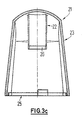
- the closure cap 20 is formed from the inner part 27 and the outer part 21 shown in FIG. 3c.
- the inner part 27 is formed from a base body 31.
- the base body 31 carries all trained for the function of the cap Elements.
- To train the backdrop guide 28 for the sliding block 19 located on the housing is a free space 31 intended.
- the free space 31 leads past a web. After this the web has been run over, it is possible to close the cap through an angle - which is preferably less than 90 ° is -, in the example shown, the angle is approximately 20 °, to twist. Then the sliding block can "fall" into the trough 32.
- the sliding block 19 In the trough 32, the sliding block 19 is held so that a twisting of the cap itself directly from this Location is not possible. So that the sliding block 19 safely in the Trough 32 arrives, the energy accumulator is on the inner part 27 29 designed in the form of a bendable material element.
- This material element is elastic in the region of the shaft 34 deformable.
- the head 35 projects into the interior of the inner part. It comes into contact with the housing 11. Because the inside of the head is also beveled is how the housing 11 is chamfered in this area, the head is pushed outwards, which creates a force is when the inner part or the cap on the Housing 11 is placed.
- the bevel then causes when no more force is exerted on the closure cap 20 acts, the elastic deformation has a tendency to recede and this force, which is supported on the housing, the Cap in the release direction on the housing 11 upwards pushes.
- Twisting the cap 20 of the sliding block 19 of the Housing in the trough 32 Twisting the cap 20 of the sliding block 19 of the Housing in the trough 32.
- the active element 30 is also a web of material that is elastic within certain limits is deformable.
- the active element 30 turns when the Cap on the housing in contact with the non-circular shape Housing 11. During twisting this will Active element 30 pressed outwards and slightly elastic deformed. This counteracts the opening of the closure cap Strength built.
- one must be determined Force must be applied to the cap put on the housing. This serves for operational safety, that the user of the discharge device is forced Apply a minimum force when opening and also when closing the housing with the closure cap a force is applied.
- Link guides 28 and force storage 29 in between and / or active element 30 are advantageously on two opposite sides Link guides 28 and force storage 29 in between and / or active element 30.
- Closure cap from the inner part 27 and from the outer part 21 to manufacture It is simple for manufacturing reasons that Closure cap from the inner part 27 and from the outer part 21 to manufacture. It is also possible to have only a one-piece cap to provide, but then shaped more complicated is or is not consistently closed to the outside has a smooth surface.
- the outer part 21 has a closed smooth outer surface 23. Inside of the outer part 21, the inner part 27 is inserted and there attached positively or non-positively. Furthermore, the interior points of the outer part 21 still designed as a hollow cylinder Molding section 22. The shaped section 22 abuts with a End to the inside of the closed area 23. At his the other end, the sealing system 26 is formed, the abuts the housing 11 so that the discharge opening 12 is enclosed.
- the lower edge is on the outer part 21 25 trained. At the lower edge 25, when on Housing 11 patch cap, one in the drawing Support the mandrel, not shown.
- the thorn is through an opening 11 provided in the housing is brought out and fixed connected to the actuator 50. This measure prevents that an actuation of the actuator 50 at closed cap is done. This increases security and prevents especially in cooperation with the timeout during the first time interval after a Operation of the actuator 50, the operational safety. An actuation of the actuating element 50 is only possible when the cap has been removed.
- the figures 4a and 4b show in two different positions the function of the guide ring 60.
- the guide ring 60 is attached to the actuator 50 and in the area thereof the upper end, that is, the housing end.
- the Housing 11 has the annular groove 15 into which the plunger web 51 of the actuating element 50 is immersed during an actuation.
- the guide ring 60 is arranged so that the Cam track 62 for the ball guided in the cam track 62 61 opens on the outside of the actuating element 50 and indeed immediately below the stop surface 16 on the housing 11.
- the stop surface 16 can be shaped so that it takes over part of the guidance of the ball 61 in the guideway.
- FIG. 4a shows the situation in which the discharge device is in a position in which discharge is possible should be. This is preferably desired when the discharge device no more than a predetermined Angle, which is preferably in a range between 30 and 35 ° lies inclined with respect to the vertical (as preferred direction) is.
- the ball 61 is in the cam track 62 of the guide ring 60 led.
- the cam track 62 has an inclined plane 63 on, so that the ball 61 is in an almost vertical position inside end stop 66 is located. Is in this position it possible an actuation stroke of the actuating element perform. To do this, only the actuator has to Actuating path can be moved relative to the housing 11.
- the ball rolls in the curved path 62. It rolls until it reaches the outer end of the Cam track has arrived and strikes the actuating element 50. It is then in the recess 65, which is on the cam track 62 is formed, held. It is now between the recess 65, ie the guide ring 60 and the formed by the housing 11 stop surface 16. Da the ball 61 has a diameter that is approximately the path corresponds to an actuation stroke, it blocks the implementation an actuation stroke, since the required clearance between the recess 65 and the stop surface 16 through the ball is filled out. Thus, an actuation of the actuating element 50 prevented as long as the inclination of the discharge device not within the preferred direction a predetermined angular position.
- the blocking position of the Ball 61 is shown in Fig. 4b.
- Fig. 5 shows the circuit diagram for an inventive Discharge device for media with an actuation lock, which can be controlled by a control unit.
- the electromagnet 75 is arranged and can be controlled by the control unit 70.
- control unit When the control unit is powered for the first time is, so a battery for power supply on the part of the actuator is installed, or by the user Contact protection from the battery or the contact elements make electrical contact with the battery the control unit allows the execution of a predetermined number of operations of the actuating element 50 without an actuation lock taking effect. These operations are used to initialize the discharge device in the way already described.
- the actuation of an actuating element is via the Dosing sensor 40 detects.
- This dosing sensor is in the actuator 50 arranged that an actuation of the actuating element 50 is detected, which exceeds a certain level.
- the sensor is preferably a switch or Pushbutton switch formed by changing the relative position switched between actuator 50 and housing 11 becomes.
- the metering sensor becomes 40 actuated, a corresponding switching signal is in the Control unit 70 generated. Then it is checked whether since the previous actuation of the actuating element 50 at least a predetermined time interval has been exceeded. If this is not the case, the electromagnet will do so activated that the actuation lock with its locking member 74 is brought into the blocking position 72. Otherwise the relay is driven so that the locking member 74 in the Release position 71 is spent. If an actuation of the Actuator 50 allows, the same time Time counter for monitoring the time interval since last actuation of the discharge device again to zero reset. Surveillance can of course also include a time counter that does not discriminate, but decriminalized back to zero. Simultaneously with the spending of the locking member 74 in the release position 71 or Lock position 72 can be an alarm signal via a signal generator be generated. The signal is preferably an acoustic one Signal.
- This procedure corresponds to the formation of the locking member 74 as a bistable element. But is this as monostable Element formed and for example by an energy store either in the locked position 72 or the release position 71 held, the electromagnet must be actuated only take place when the blocking element is switched should be done.
- a bias of the monostable locking member 74 in the Release position 71 has the advantage that if the Electronics a discharge by actuating the actuating element 50 can take place, but then an uncontrolled, disregarding the interval of the first time interval Discharge is possible.
- pre-tensioning the monostable prevents Locking member 74 in the locking position 72 this uncontrolled Discharge in the event of an error, but then is also a the first time interval due to the blocking position 72 of the locking member 74 impossible.
- mechanical means removable Securing element
- the release position 71 or the locking position 72 of the locking member 74 is detected by the control sensors 41.
- the control sensors 41 become from the first and second pairs of contact pins formed, which contacts the contact piece 84 and so grasp the situation.
- Via the switch 78 can a new start can be generated with the given Number of operations of the actuator 50 without intervention the actuation lock can be carried out.
- about the interface 79 can also be connected to the control unit accessed and data communication carried out.
- the parameters of the control unit 70 can be set and recorded data on the use of the Discharge device can be read out.
Landscapes
- Health & Medical Sciences (AREA)
- Engineering & Computer Science (AREA)
- Life Sciences & Earth Sciences (AREA)
- Heart & Thoracic Surgery (AREA)
- Animal Behavior & Ethology (AREA)
- Pulmonology (AREA)
- Anesthesiology (AREA)
- Biomedical Technology (AREA)
- Biophysics (AREA)
- Hematology (AREA)
- Bioinformatics & Cheminformatics (AREA)
- General Health & Medical Sciences (AREA)
- Public Health (AREA)
- Veterinary Medicine (AREA)
- Infusion, Injection, And Reservoir Apparatuses (AREA)
- Nozzles (AREA)
- Electrical Discharge Machining, Electrochemical Machining, And Combined Machining (AREA)
- Photographic Developing Apparatuses (AREA)
- Spray Control Apparatus (AREA)
Abstract
Description
Die Erfindung betrifft eine Austragvorrichtung für Medien. Derartige Austragvorrichtungen werden insbesondere für das Versprühen eines Fluids verwendet. Vorzugsweise enthält das Fluid einen oder mehrere pharmazeutische Wirkstoffe.The invention relates to a discharge device for media. Such discharge devices are used in particular for the Spraying a fluid used. This preferably contains Fluid one or more active pharmaceutical ingredients.
Solche Austragvorrichtungen sind zum Beispiel aus der DE 198 07 921 bekannt und weisen ein Gehäuse auf, an dem ein Betätigungselement relativ beweglich angeordnet ist. Das Betätigungselement kann dabei um einen dem Weg eines Betätigungshubes entsprechenden Weg bzgl. dem Gehäuse bewegt werden. Es ist eine Steuereinheit vorgesehen, die zumindest die Zeit seit der letzten Betätigung des Betätigungselementes erfaßt. Des weiteren ist eine durch die Steuereinheit angesteuert betätigbare Betätigungssperre vorgesehen, wobei die Betätigungssperre in ihrer Sperrstellung die Durchführung eines Betätigungshubes sperrt und in ihrer Freigabestellung die Durchführung eines Betätigungshubes freigibt. Such discharge devices are for example from DE 198 07 921 known and have a housing on which a Actuator is arranged relatively movable. The The actuating element can thereby move the path of an actuating stroke corresponding path with respect to the housing. A control unit is provided, which at least the Time recorded since the last actuation of the actuating element. Furthermore, one is controlled by the control unit actuatable actuation lock provided, the actuation lock in its locked position performing a Actuating stroke blocks and in its release position Carries out an actuation stroke releases.
Derartige Austragvorrichtungen finden dann Anwendung, wenn zur Vermeidung einer zu hohen Wirkstoffkonzentration die Abgabe des auszutragenden Mediums zeitlich gestreckt werden soll. Dies ist beispielsweise insbesondere dann der Fall, wenn das auszutragende Medium einen pharmazeutischen Wirkstoff oder eine Wirkstoffkombination enthält und vom Patienten selbst verabreicht werden soll. Durch die Möglichkeit, eine Betätigung des Betätigungselementes für eine gewisse Zeit nach der Durchführung eines Betätigungshubes zu sperren, wird eine zu rasch aufeinander folgende Abgabe des Wirkstoffes verhindert.Such discharge devices are used when to avoid excessive drug concentration of the medium to be discharged should. This is particularly the case, for example, if the medium to be dispensed is an active pharmaceutical ingredient or contains an active ingredient combination and from the patient self-administered. By being able an actuation of the actuating element for a certain Block time after performing an actuation stroke, is a too rapid successive release of the active ingredient prevented.
Aufgabe der Erfindung ist es, eine einfach handhabbare und Langzeit-anwendbare Austragvorrichtung zu schaffen.The object of the invention is an easy to handle and To create long-term applicable discharge device.
Die Aufgabe der Erfindung wird bei Zugrundelegen der gattungsgemäßen Merkmale des Oberbegriffes durch die kennzeichnenden Merkmale der unabhängigen Patentansprüche gelöst.The object of the invention is based on the generic Characteristics of the generic term by the characteristic Features of the independent claims solved.
Eine erfindungsgemäße Austragvorrichtung für Medien, insbesondere zum Versprühen eines vorzugsweise einen pharmazeutischen Wirkstoff enthaltenden Fluids weist ein Gehäuse auf. An dem Gehäuse ist ein Betätigungselement angeordnet, das um einen dem Weg eines Betätigungshubes entsprechenden Weg relativbeweglich bzgl. dem Gehäuse ist. Die Austragvorrichtung weist eine Steuereinheit auf, die wenigstens die seit der letzten Betätigung des Betätigungselementes verstrichene Zeit erfaßt. Eine Betätigungssperre, die durch die Steuereinheit angesteuert betätigbar ist, bewirkt in ihrer Sperrstellung die Durchführung eines Betätigungshubes und gibt einen Betätigungshub in ihrer Freigabestellung frei. Eine derartige Betätigungssperre weist ein Sperrglied auf, wobei das Sperrglied mittels eines Elektromagneten aus der Freigabestellung in die Sperrstellung und/oder aus der Sperrstellung in die Freigabestellung verbringbar ist.A discharge device for media according to the invention, in particular for spraying a preferably a pharmaceutical Fluids containing active substance has a housing. On an actuating element is arranged around the housing a path corresponding to the path of an actuation stroke is relatively movable regarding the housing. The discharge device has a control unit that has at least the since time elapsed after actuation of the actuating element detected. An actuation lock by the control unit is actuated actuated, causes in its locked position the execution of an actuation stroke and gives an actuation stroke free in their release position. Such an operating lock has a locking member, the locking member by means of an electromagnet from the release position in the locked position and / or from the locked position in the Release position is transferable.
Durch diese Maßnahme wird in vorteilhafter Weise sichergestellt, daß zum Umschalten der Betätigungssperre von der Sperrstellung in die Freigabestellung und umgekehrt nur eine relativ kleine Menge an Energie erforderlich ist, nämlich die Menge, um einen Elektromagneten, vorzugsweise entsprechend einem Relais, kurzzeitig zu bestromen und ein elektromagnetisches Feld ausreichender Stärke kurzzeitig aufzubauen. Die Sperrwirkung der Betätigungssperre wird dadurch erreicht, daß das Sperrglied so in die Mechanik des Betätigungselementes eingreift, daß eine Sperrwirkung auftritt. Dabei ist das Sperrglied entsprechend abgestützt und die die Sperre bewirkende Kraft muß nicht durch den Elektromagneten oder durch die Energieversorgung der Betätigungssperre selbst aufgebracht werden.This measure advantageously ensures that to switch the actuation lock from the Locked position in the release position and vice versa only one relatively small amount of energy is required, namely the Amount to an electromagnet, preferably accordingly a relay to energize briefly and an electromagnetic Build up a field of sufficient strength for a short time. The Locking effect of the actuation lock is achieved in that the locking member in the mechanics of the actuator intervenes that a blocking effect occurs. It is Locking member supported accordingly and the one causing the lock Power does not have to go through the electromagnet or through the power supply of the actuation lock itself applied become.
Eine bevorzugte Ausgestaltung der Austragvorrichtung ist dann gegeben, wenn die Betätigung gesperrt ist, wenn seit der vorherigen Betätigung ein vorgegebenes Zeitintervall noch nicht verstrichen ist.A preferred embodiment of the discharge device is then given when the operation is locked, if since the previous Not yet actuated a predetermined time interval has passed.
Weiter wird eine Austragvorrichtung bevorzugt, die einen Kontaktschalter aufweist, der in den Stromkreis eingebunden ist, der den Elektromagneten versorgt und der die Stromversorgung des Elektromagneten unterbricht, solange nicht das Betätigungselement nicht um einen Mindestweg aus seiner unbetätigten Ruhelage herausbewegt wurde. Vorzugsweise ist der Betrag des Mindestweges geringer als der Leerweg des Betätigungselementes zu Beginn eines Betätigungshubes.Furthermore, a discharge device is preferred which has a contact switch which is integrated in the circuit, that supplies the electromagnet and that supplies the power supply of the electromagnet interrupts as long as the actuator is not not a minimum way out of his unactuated Rest position was moved out. Preferably the amount the minimum travel less than the free travel of the actuating element at the beginning of an actuation stroke.
Gemäß einer ersten bevorzugten Ausgestaltung der Erfindung ist das Sperrglied als bistabiles Element ausgebildet und befindet sich somit ohne ständige Einwirkung einer Kraft entweder in der Freigabestellung oder in der Sperrstellung. Gemäß alternativer Ausgestaltungen der Erfindung ist es möglich, das Sperrglied monostabil auszubilden. Demgemäß verharrt das Sperrglied in Einwirkungskraft freier Stellung entweder in der Sperrstellung bzw. in der Freigabestellung und wird auf die Dauer der Einwirkung des Elektromagneten in der Freigabestellung bzw. in der Sperrstellung gehalten.According to a first preferred embodiment of the invention the locking member is designed and located as a bistable element thus either without constant action of a force in the release position or in the locked position. According to alternative embodiments of the invention it is possible to form the blocking member monostable. Accordingly, this persists Locking element in the free position either in the locked position or in the release position and is on the duration of the action of the electromagnet in the release position or held in the locked position.
Gemäß einer bevorzugten Fortbildung der Merkmale des Oberbegriffes des Anspruchs 1 wird ein Schalter an der Austragvorrichtung angeordnet, der manuell betätigbar ist und dessen Betätigung es erlaubt, eine vorgegebene, geringe Anzahl von Betätigungshüben durchzuführen, ohne daß die Betätigungssperre in Sperrstellung gebracht wird. Dabei wird nach dem Betätigen des Schalters die Durchführung einer geringen Anzahl von Betätigungshüben, insbesondere zwischen zwei und zehn Betätigungshüben, ohne Eingriff der Betätigungssperre ermöglicht. Diese Maßnahme ermöglicht es, bei erfindungsgemäßen Austragvorrichtungen, zum Beispiel bei Pumpenzerstäubern, sicherzustellen, daß bei dem ersten Betätigungshub, der dem Patienten verabreicht wird, die vorgegebene Austragmenge ausgegeben wird. Insbesondere bei Pumpzerstäubern, aber auch bei anderen Austragvorrichtungen, ist es konstruktionsbedingt, daß nach langem Lagern oder aber schon vom Verpackungszeitpunkt her, beispielsweise aufgrund der Erfordernisse einer sterilen oder wenigsten nahezu keimfreien Verpackung, zunächst eine Initialisierung (Priming) der Austragvorrichtung bzw. der Saugpumpe vorzunehmen. Dazu müssen mehrere Pumphübe durchgeführt werden, wobei während der Pumphübe zunächst nur teilweise auszutragendes Medium gefördert wird und zum anderen Teil, der mit fortschreitender Anzahl von Betätigungshüben abnimmt, auch der Austrag von Luft stattfindet. Vorzugsweise abhängig von dem Volumen des Pumpzerstäubers oder anderer technischer Gegebenheiten beim ersten oder bei den ersten wenigen Austraghüben ist es erforderlich, vor der ersten Anwendung des Austragelementes diese "Leer"-Betätigungen durchzuführen, damit bei der ersten Betätigung, die der Applikation des Wirkstoffes dient, auch sichergestellt ist, daß die erwünschte und vorgeschriebene Quantität an Medium ausgetragen wird. Bei Pumpzerstäubern ist die Anzahl der erforderlichen Hübe davon abhängig, wie groß das Volumen des Pumpzerstäubers ist, also wie groß das Volumen eines Austrages oder eines Betätigungshubes ist. Ferner ist es auch abhängig von dem auszutragenden Medium. Im Zweifel ist die erforderliche Anzahl an Leer-Betätigungshüben zu Beginn der Benutzung der Austragvorrichtung empirisch zu bestimmen und entsprechend vorzugeben.According to a preferred development of the features of the generic term of claim 1 is a switch on the discharge device arranged, which is manually operable and its Operation allows a predetermined, small number of Perform actuation strokes without the actuation lock is brought into the locked position. It is after pressing the switch performing a small number actuation strokes, in particular between two and ten actuation strokes, allows without intervention of the actuation lock. This measure makes it possible in the case of the invention Discharge devices, for example in the case of pump atomizers, ensure that the first actuation stroke that the The patient is administered, the specified discharge amount is issued becomes. Especially with pump atomizers, but also with other discharge devices, it is due to the design, that after long storage or from the time of packaging forth, for example due to the requirements of a sterile or at least almost sterile packaging, initially an initialization (priming) of the discharge device or the suction pump. This requires several pumping strokes be carried out, initially only during the pumping strokes medium to be discharged is promoted and the other Part that with increasing number of actuation strokes decreases, the discharge of air also takes place. Preferably depending on the volume of the pump sprayer or others technical circumstances at the first or at the first a few discharge strokes are required before the first application of the discharge element to carry out these "empty" operations, with the first actuation, that of the application the active ingredient is used, it is also ensured that the desired and prescribed quantity of medium carried out becomes. With pump atomizers, the number is required Strokes depend on how large the volume of the pump atomizer is is the size of the volume of a discharge or an actuation stroke. It is also dependent on the medium to be discharged. When in doubt, the required one Number of empty actuation strokes at the start of using the Discharge device to be determined empirically and accordingly to specify.
Gemäß einer bevorzugten Ausgestaltung dieser Vorrichtung ist ein zweites Zeitintervall vorgegeben, während dessen die vorgegebene Anzahl von Betätigungshüben durchgeführt werden muß. Wird das zweite Zeitintervall überschritten, so kann insbesondere vorgesehen werden, die Betätigungssperre in ihre Sperrstellung zu verbingen. Dadurch wird sichergestellt, daß ein zeitlicher Zusammenhang zwischen Betätigung des Schalters und der Durchführung der Anzahl von Betätigungshüben eingehalten wird. Dies dient insbesondere dem Ausschluß von Fehlbetätigungen und Fehlbedienungen durch den Benutzer. Gleichzeitig soll vermieden werden, daß durch wiederholte Betätigung des Schalters in einfacher Weise eine Überdosierung des Wirkstoffes herbeigeführt wird.According to a preferred embodiment of this device predetermined a second time interval during which the predetermined Number of actuation strokes must be carried out. If the second time interval is exceeded, in particular be provided the actuation lock in their To lock position. This ensures that a temporal relationship between actuation of the switch and performing the number of actuation strokes becomes. This serves in particular to prevent incorrect operation and incorrect operation by the user. At the same time should be avoided by repeated actuation the switch in an easy way overdosing the Active ingredient is brought about.
Gemäß einer weiteren erfindungsgemäßen Ausgestaltung einer Austragvorrichtung weist die Steuereinheit eine von außen zugängliche Schnittstelle auf, über die auf die Steuereinheit eingewirkt werden kann. Die Schnittstelle ist dabei von außen zugänglich. Über die Schnittstelle kann zumindest einer der folgenden Parameter für die Ansteuerung der Betätigungssperre durch die Steuereinheit eingestellt werden: Dauer des ersten Zeitintervalls, Dauer des zweiten Zeitintervalls und Anzahl der Betätigungshübe, die nach Betätigung des Schalters durchführbar ist.According to a further embodiment of the invention The control unit has a discharge device that is accessible from the outside Interface on, on to the control unit can be influenced. The interface is from the outside accessible. At least one of the following parameters for the activation of the actuation lock can be set by the control unit: duration of the first Time interval, duration of the second time interval and number the actuation strokes that can be carried out after actuation of the switch is.
Diese Ausbildung der Erfindung hat den Vorteil, daß die einfache Anpassung an unterschiedliche Zeitintervalle und unterschiedliche Anzahlen von Leer-Betätigungshüben zu Beginn einer Benutzung einer Austragvorrichtung variabel vorgegeben werden kann. Es kann in Abhängigkeit der Befüllung der Austragvorrichtung und der Dimensionierung der Austragvorrichtung insbesondere zum Beispiel auch in der Apotheke bei der Abgabe eines Medikamentes die erforderliche Einstellung, vorzugsweise Patienten-individuell, vorgenommen werden. Somit wird eine höhere Flexibilität der Austragvorrichtungen und eine bessere Anpassung an unterschiedliche Patienten und Wirkstoffe ermöglicht.This embodiment of the invention has the advantage that the simple Adaptation to different time intervals and different Number of empty actuation strokes at the beginning variable use of a discharge device can be. It can depend on the filling of the discharge device and the dimensioning of the discharge device especially in the pharmacy at Dispensing a drug the required setting, preferably Patient-specific. Consequently is a higher flexibility of the discharge devices and better adaptation to different patients and Active ingredients enables.
Gemäß einer vorteilhaften Ausgestaltung der Erfindung ist es möglich, vorzusehen, daß die nach Betätigung des Schalters mögliche aufeinanderfolgende Anzahl von Betätigungen nur dann durchführbar ist, wenn gleichzeitig an der Schnittstelle ein Kommunikationsmittel kontaktiert ist. Bei dem Kommunikationsmittel kann es sich dabei entweder um einen Computer oder aber auch nur um ein passives Teil handeln. Auf diese Weise kann in vorteilhafter Art sichergestellt werden, daß die Durchführung der Anzahl von Betätigungen ohne Eingriff der Betätigungssperre nur von geschultem Personal, beispielsweise dem Apotheker bei der Abgabe des Medikamentes, durchgeführt werden kann. Dies erhöht nochmals die Sicherheit für den Benutzer. Es ist so nicht mehr möglich, die Betätigungssperre durch mehrmaliges Betätigen des Schalters zu umgehen. According to an advantageous embodiment of the invention, it is possible to provide that after pressing the switch possible consecutive number of operations only then is feasible if at the same time at the interface Means of communication is contacted. With the means of communication can either be a computer or but only act as a passive part. In this way can be ensured in an advantageous manner that the Execution of the number of operations without intervention of the Operation lock only by trained personnel, for example the pharmacist when dispensing the drug can be. This further increases security for the user. It is no longer possible to lock the actuator bypassing the switch several times.
Gemäß einer vorteilhaften Weiterbildung der Erfindung kann vorgesehen sein, daß die vorgebbare Anzahl von Betätigungshüben, die nacheinander ohne Eingreifen der Betätigungssperre, bei der ersten Betätigung des Betätigungselementes durchführbar ist. Dies ermöglicht es, die Inbetriebnahme der Austragvorrichtung ohne weitere Maßnahmen in einfacher Weise zu ermöglichen und ohne daß dem Benutzer zwangsläufig die Möglichkeit dazu gegeben wird, auch zu einem späteren Zeitpunkt mehrere aufeinanderfolgende Betätigungshübe durchzuführen, ohne daß das Eingreifen der Betätigungssperre dies verhindern würde.According to an advantageous development of the invention be provided that the predeterminable number of actuation strokes, one after the other without intervention of the actuation lock, feasible when the actuating element is actuated for the first time is. This enables the discharge device to be started up in a simple manner without further measures and without necessarily giving the user the opportunity is given, even at a later point in time perform successive actuation strokes without that the intervention of the actuation lock prevent this would.
Gemäß vorteilhafter Ausgestaltung der Erfindung ist ein einmaliges Betätigen des Betätigungselementes und somit die Durchführung eines Austraghubes auch nach der Ausfall der Energieversorgung möglich. Gemäß vorteilhafter Ausgestaltung besteht diese Möglichkeit nach irreversiblem Entfernen eines Sicherungselementes.According to an advantageous embodiment of the invention is unique Actuate the actuator and thus the Carrying out a discharge stroke even after the failure of the Energy supply possible. According to an advantageous embodiment there is this possibility after irreversibly removing one Securing element.
Die Unteransprüche enthalten vorteilhafte Weiterbildungen der Ausgestaltungen gemäß den unabhängigen Patentansprüchen. Im übrigen ist die Erfindung auch anhand der in der Zeichnung dargestellten Ausführungsbeispiele noch näher erläutert; dabei zeigen:
- Fig. 1
- die Teilschnitt-Darstellung einer erfindungsgemäßen Austragvorrichtung für Medien;
- Fig. 2a bis Fig. 2e
- die im Betätigungselement angeordnete Steuereinheit mit der ansteuerbaren Betätigungssperre in Freigabestellung und in Sperrstellung;
- Fig. 3a bis Fig. 3c
- die Darstellung einer erfindungsgemäßen Verschlußkappe mit Kulissenführung;
- Fig. 4a und Fig. 4b
- die Ausgestaltung eines gravitationsabhängig schaltenden Sperrmittels in einer die Betätigung ermöglichenden Stellung und in einer die Betätigung verhindernden Stellung; und
- Fig. 5
- ein Blockschaltbild einer Steuereinheit und der von ihr betätigbaren Betätigungssperre.
- Fig. 1
- the partial sectional view of a discharge device according to the invention for media;
- Fig. 2a to Fig. 2e
- the control unit arranged in the actuating element with the actuatable actuating lock in the release position and in the blocking position;
- 3a to 3c
- the representation of a closure cap according to the invention with a guide;
- 4a and 4b
- the design of a gravity-dependent switching locking means in a position enabling the operation and in a position preventing the operation; and
- Fig. 5
- a block diagram of a control unit and the actuation lock actuated by it.
Die Fig. 1 zeigt in teilgeschnittener Darstellung eine Austragvorrichtung für Medien, wie sie insbesondere zum Versprühen eines Fluids, das vorzugsweise einen pharmazeutischen Wirkstoff enthält, verwendet werden kann.1 shows a discharge device in a partially sectioned illustration for media such as those used for spraying a fluid, preferably a pharmaceutical Contains active ingredient, can be used.
Die Austragvorrichtung weist ein Gehäuse 11 auf. In dem Gehäuse
sind, nach außen verschlossen, die funktionalen Elemente
angeordnet. Das Gehäuse weist zum Austragen des Mediums,
insbesondere eines Fluids, eine Austragöffnung 12 auf. Damit
eine Verschmutzung im Bereich der Austragöffnung 12 und somit
auch eine eventuelle Verkeimung oder eine Verseuchung mit
Bakterien möglichst vermieden wird, wird das Gehäuse mit der
verrastend auf ihm aufsetzbaren Verschlußkappe 20 verschlossen.
Die Verschlußkappe 20 wird dabei aus einem Außenteil 21
und einem Innenteil 27 gebildet. Dabei verbleibt zwischen dem
unteren Rand der Verschlußkappe 25 und dem zugeordneten Gehäuseabschnitt
ein schmaler Spalt 24. Ansonsten bildet Gehäuse
11 zusammen mit der aufgesetzten Verschlußkappe 20 eine
weitgehend gleichmäßige und geschlossene Oberfläche aus. Das
Außenteil 21 der Verschlußkappe weist auch noch den Formabschnitt,
der hier die Form eines Hohlzylinders hat und von
innen an der geschlossenen Fläche 23 des Außenteils 21 angeordnet
ist und in das Innenteil 27 der Verschlußkappe 20 hineinragt.
Der Formabschnitt 22 umschließt das Gehäuse 11 in
dem Bereich, der die Austragöffnung 12 beinhaltet und liegt
im Bereich der Anlagefläche 26 dichtend am Gehäuse an. Dadurch
wird sichergestellt, daß keine Luft von außen mit dem
im hohlzylindrischen Abschnitt des Formabschnitts 22, der
durch die dichtende Anlage 26 am Gehäuse verschlossen wird,
ausgetauscht werden kann. Dadurch wird einer Verschmutzung
bzw. einer Verkeimung des Gehäuses 11 im Bereich der Austragöffnung
12 verhindert. Das Innenteil 27 der Verschlußkappe 20
weist eine Kulissenführung 28 für den Gleitstein 19, der am
Gehäuse 11 ausgebildet ist, auf. Die Kulissenführung ist in
dieser teilgeschnittenen Darstellung nicht ersichtlich.The discharge device has a
An seinem der Verschlußkappe 20 abgewandten Ende weist das
Gehäuse 11 Griffflächen 14 auf, an denen während der Benutzung
der Austragvorrichtung das Gehäuse 11 gehalten werden
kann. An seinem unteren Ende ist das Gehäuse geöffnet und
wird durch das Betätigungselement 50 verschlossen. Zur Führung
des Betätigungselementes 50 im Gehäuse 11 ist die Ringnut
15 im Gehäuse ausgebildet, in die bei der Betätigung der
entsprechende Tauchsteg 51 des Betätigungselementes eintaucht.
Die Strecke eines Betätigungshubes des Betätigungselementes
wird dabei im Zusammenwirken zwischen der Tiefe der
Ringnut 15 des Gehäuses 11 und der Länge des Tauchsteges 51
am Betätigungselement 50 festgelegt. In der gewählten Ausführung
der Erfindung ist der Betätigungshub dadurch begrenzt,
daß der Tauchsteg 51 am Boden der Ringnut 15 anstößt. In
nicht betätigter Stellung des Betätigungselementes 50 ist
daher ein Spalt zwischen Betätigungselement 50 und Gehäuse 11
vorhanden. Dieser Spalt kann mit einem Originalitätsschutz
verschlossen werden, der Sollbruchstellen aufweist und daher
entfernbar ist. At its end facing away from the cap 20, the
Lagefest mit dem Gehäuse 11 ist, zur Austragöffnung 12 führend
und den Austragkanal beinhaltend, das Distanzstück 13
angeordnet. Die Länge des Distanzstückes 13 bestimmt sich aus
dem im Gehäuse 11 verbleibenden Platz in Abhängigkeit mit der
Größe des Behälters 54. Je größer der Behälter 54 gewählt
wird, desto mehr Betätigungen der Betätigungselemente 50
können durchgeführt werden, bevor der Behälter 54 entleert
ist. Das Distanzstück 13 ist dabei lagefest zum Gehäuse 11
angeordnet. Im Gegensatz dazu ist der Behälter 54 lagefest am
Betätigungselement 50 angeordnet. Der Behälter 54 ist mittels
des Crimp-Ringes 55 durch die Saugpumpe 56 verschlossen. Der
Kolbenstößel 57 der Saugpumpe 56 ist dabei so ausgebildet,
daß er sich in Anlage mit dem Distanzstück 13 befindet, wobei
zum Austragen des auszutragenden Mediums ein durchgehender
Kanal durch den Kolbenstößel 57 und das Distanzstück 13 hindurch
zur Austragöffnung 12 ausgebildet ist. Der Behälter 54
ist selbst über den am Crimp-Ring 55 angreifenden Halter 53
an dem Tragelement 52 befestigt. Das Tragelement 52 selbst
ist wiederum, zumindest mittelbar, an dem Betätigungselement
50 befestigt.Is in position with the
Im Bereich des unteren Abschlusses des Gehäuses 11, der durch
die Anschlagfläche 16 gebildet wird, ist im Betätigungselement
50, als mechanisch ausgeführtes Schaltmittel eines gravitationsabhängig
schaltenden Sperrmittels, der Führungsring
60 angeordnet. In dem Führungsring 60 sind mehrere, in dem
dargestellten Beispiel drei jeweils um 120° zueinander versetzte
Kurvenbahnen 62 eingebracht, in denen eine Kugel 61
geführt ist. In der Darstellung der Fig. 1 ist aber lediglich
eine Kurvenbahn 62 ersichtlich. Die Kurvenbahn 62 weist an
ihrem inneren Ende die Anschlagfläche 66 auf, an der in dieser
Ausrichtung der Austragvorrichtung die Kugel 61 anliegt.
In dieser Stellung ermöglicht die Kugel die Durchführung
eines Betätigungshubes des Betätigungselementes 50. Die Kurvenbahn
weist außer ihrem Endanschlag 66 eine Rampe in Form
einer schiefenen Ebene 63 auf, die gegenüber der Horizontalen
den Neigungswinkel 64 aufweist. Dieser Neigungswinkel bestimmt,
ab welcher Neigung der Austragvorrichtung die Kugel
in der Kurvenbahn 62 geführt, auf der Rampe zu rollen und
schließlich in die andere, äußere Endlage, die durch die
Rastmulde 65 gebildet wird, gelangt. In der Rastmulde 65
liegt die Kugel 61 gehalten zwischen dem Führungsring 60, der
fest an dem Betätigungselement 50 befestigt ist und der Anschlagsfläche
16 des Gehäuses 11. Da der Durchmesser der
Kugel wenigstens nahezu dem Betätigungsweg eines Betätigungshubes
entspricht, wird dann, wenn sich die Kugel 61 in dieser
Lage befindet, eine Betätigung des Betätigungselementes gesperrt.
Statt drei Kurvenbahnen 62 können auch zwei oder vier
Kurvenbahnen vorgesehen sein. Werden zwei Kurvenbahnen vorgesehen,
so müssen diese so ausgebilet sein, daß sie doppelseitig
arbeiten, d.h. eine Neigung gegenüber der Vorzugsrichtung,
in der die Austragvorrichtung ausgerichtet sein soll
- meist die Vertikale -, in einer Richtung auf beiden Seiten
erfaßt. Wichtig dabei ist nur, daß die Kurvenbahnen 62 die
Neigung in einer beliebigen Richtung gegenüber der Vorzugsrichtung
erfassen können, also in wenigstens zwei unabhängige
Richtungskomponenten auflösen.In the area of the lower end of the
Ferner ist in dem Betätigungselement 50 auch die Steuereinheit
70 angeordnet, die eine Zeiterfassung und eine Erfassung
der Betätigungen des Betätigungselementes beinhaltet. Die
Steuereinheit ist in der Lage, das Sperrglied 74 zwischen
einer Freigabestellung 71 und einer Sperrstellung hin- und
herzuschalten. Dies geschieht mittels des Elektromagneten 75,
der durch die Steuereinheit 70 ansteuerbar ist und der auf
das Sperrglied 74 einwirken kann. Furthermore, the control unit is also in the
Die Fign. 2a und 2b zeigen eine Ansicht des Betätigungselementes
50 mit der in dem Betätigungselement 50 angeordneten
Betätigungssperre. Die Betätigungssperre wird gebildet aus
der Steuereinheit 70, dem Elektromagneten 75 sowie dem Sperrglied
74. Vorzugsweise sind diese Elemente auf einer gemeinsamen
Grundplatte 73 angeordnet, wobei die Grundplatte im
Betätigungselement 50 vorzugsweise durch Verrasten befestigt
wird.The figures 2a and 2b show a view of the
Die Fig. 2a zeigt das Sperrglied 74 in der Freigabestellung
71 der Betätigungssperre, während in der Fig. 2b, die ansonsten
mit der Fig. 2a übereinstimmt, das Sperrglied 74 in der
Sperrstellung 72 der Betätigungssperre.2a shows the locking
Die Energieversorgung, die in der Zeichnung nicht dargestellt
ist, erfolgt über eine Batterie, vorzugsweise eine Knopfzelle
oder Ähnliches, und ist zum Beispiel unterhalb der Grundplatte
73 angeordnet. Mit einem Kondensator kann die Energieversorgung
gepuffert werden, was beispielsweise die Aufrechterhaltung
der Speicherwerte bei einem Batteriewechsel oder aber
eine letztmalige Betätigung des Betätigungselementes 50 nach
Ausfall der Versorgung durch die Batterie ermöglicht. Die
Grundplatte 73 ist dabei vorzugsweise gleichzeitig als Platine
ausgebildet, die die entsprechenden elektrischen Leitungen
aufweist. Dazu zählen insbesondere die elektrischen Verbindungen
zwischen der Steuereinheit 70 und dem Elektromagneten
75. Der Elektromagnet 75 ist ebenfalls auf der Grundplatte
73 angeordnet. Er wirkt auf einen an dem Sperrglied 74
ausgebildeten Magnetkörper 77 ein. Der Magnetkörper 77 dient
dazu, unter dem Einfluß der zwischen Magnetkörper 77 und dem
als Stromrelais ausgebildeten Elektromagneten 75 wirkenden
elektromagnetischen Kräfte eine Umschaltbewegung des Sperrgliedes
74 zu erzeugen. Das Sperrglied 74 wird dabei in der
dargestellten Ausführungsform durch Verschwenken um seine
Mittelachse von der Freigabestellung 71 in die Sperrstellung
und umgekehrt verbracht.The energy supply, which is not shown in the drawing
is done via a battery, preferably a button cell
or the like, and is for example below the
Eine Ausschnittszeichnung des Sperrgliedes 74 ist in Aufsicht
und in Seitenansicht in den Fign. 2c bzw. 2d dargestellt.A sectional drawing of the locking
Zur Erfassung der Lage des Sperrgliedes 74 ist an ihm ein
Haltearm 83 ausgebildet, an dessen Ende ein Kontaktstück 84
angeordnet ist. Auf der Grundplatte 73 sind beidseitig des
Kontaktstückes 84 erste bzw. zweite Kontaktstiftpaare 86, 87
angeordnet.To detect the position of the locking
In der in Fig. 2a dargestellten Freigabestellung 71 wird mittels
des Kontaktstückes 84 die elektrische Verbindung zwischen
den beiden Kontaktstiften des zweiten Kontaktstiftpaares
87 geschlossen und somit ein Signal für die Steuereinheit
70 generiert, das anzeigt, daß sich das Sperrglied 74
tatsächlich in der Freigabestellung 71 befindet. Wird das
Sperrglied 74 durch die Wirkung des Elektromagneten 75 in die
in Fig. 2b dargestellte Sperrstellung verbracht, so wird die
Kontaktierung des zweiten Kontaktstiftpaares 87 über das Kontaktstück
84 unterbrochen und am Ende der Betätigung die
elektrische Verbindung der Kontaktstifte des ersten Kontaktstiftpaares
86 über das Kontaktstück 84 hergestellt. Somit
wird nunmehr ein Signal für die Steuereinheit 70 generiert,
das signalisiert, daß sich die Grundplatte 73 in der Sperrstellung
72 befindet. Zugleich ist es möglich, die Sperrkörper
89 an ihrer gehäuseseitigen Fläche mit einer Farbmarkierung
zu versehen, die über ein gehäuseseitiges Sichtfenster
erfaßbar ist, und eine optische Information über die Schaltstellung
des Sperrgliedes liefert (z.B. grün = Freigabe-, rot
= Sperrstellung). In the
Die Fig. 2e zeigt die Ansicht des Betätigungselementes 50 von
unten, der Gehäuseaußenseite des Betätigungselementes 50.
Diese weist an ihrer Bodenfläche 58 zum einen den Schalter 78
und zum anderen die Schnittstelle 79 auf. Über den Schalter
78, der insbesondere als versenkt angeordneter Tastschalter
ausgebildet sein kann, dessen Betätigung beispielsweise nur
mittels eines Hilfsmittels, vorzugsweise einem spitzen Gegenstand,
beispielsweise einer Bleistiftspitze, durchgeführt
werden kann, angeordnet. Des weiteren ist auf der Bodenfläche
58 auch die Schnittstelle 79 angeordnet. Die Schnittstelle 79
dient der Kontaktierung eines Informationsmittels mit der
Steuereinheit 70. Bei dem Informationsmittel kann es sich
entweder um ein passives Bauteil, im einfachsten Fall um eine
Kontaktierungsbrücke oder aber auch um eine Eingabe-/Ausgabeeinheit,
wie zum Beispiel einen PC, handeln, über den Daten,
vorzugsweise Parameter für die Funktion der Steuereinheit 70,
an diese übertragen werden können und auch Informationen aus
der Steuereinheit ausgelesen werden können. Bei den Parametern,
die an die Steuereinheit 70 übertragen werden können,
handelt es sich insbesondere um den Wert des ersten Zeitintervalls,
der beginnt, wenn eine Betätigung des Betätigungselementes
erfolgt und das den Zeitraum festlegt, der vor der
nächsten Betätigung des Betätigungselementes verstreichen
muß, damit kein Sperren der Betätigung erfolgt. Ferner kann
auch das zweite Zeitintervall als Parameter in die Steuereinheit
70 übertragen werden. Das zweite Zeitintervall bestimmt
die Zeit, während der nach Betätigung des Schalters 78 eine
vorgegebene Anzahl von Betätigungen des Betätigungselementes
durchgeführt werden kann, ohne daß die Betätigungssperre eingreift.
Ebenso ist diese Anzahl von Betätigungen, die ohne
Eingreifen der Betätigungssperre nach Betätigen des Schalters
78 durchführbar ist, über die Schnittstelle 79 vorgebbar. Bei
der Schnittstelle 79 kann es sich also insbesondere um eine
Steckverbindung eines Datenbusses für die Steuereinheit 70
handeln. Als Datenbus kommen bevorzugt Zweidraht-Datenbusse
in Betracht. Des weiteren ist es möglich, über die Schnittstelle
79 auch Informationen aus der Steuereinheit 70 auszulesen.
Es können beispielsweise die Anzahl der erfolgten
Betätigungshübe sowie die Anzahl der Betätigungen des Schalters
78 erfaßt werden. Ferner wäre es auch möglich, zu erfassen,
wie oft das Betätigungselement vor Ablauf des ersten
Zeitintervalls nach der vorhergehenden Betätigung des Betätigungselementes
erfolgt ist. Diese Information kann insbesondere
als Maß für das Bedürfnis des Patienten gewertet werden,
eine höhere Wirkstoffdosis verabreicht zu bekommen. Welche
Parameter vorgebbar sind und welche Informationen aus der
Steuereinheit 70 ausgelesen werden, kann entsprechend den
Bedürfnissen festgelegt werden. Dies ist lediglich bei der
Gestaltung der Steuereinheit 70 entsprechend zu berücksichtigen.2e shows the view of the
In einfacherer Ausbildung kann das Informationselement auch
lediglich eine Kontaktbrücke zur elektrischen Kontaktierung
zwischen den beiden Einzellitzen, die an der Schnittstelle 79
enden, ausgebildet sein. Vorzugsweise liegt die Kontaktbrücke
in Form eines gesondert geformten Steckers vor, der zum Beispiel
nur an einen eingeschränkten Personenkreis, wie Krankenschwestern
und Apotheker, ausgegeben wird. Wird die Präsenz
des Brückensteckers an der Schnittstelle 79 verlangt,
wenn der Schalter 78 betätigt wird, so kann in dieser Weise
sichergestellt werden, daß nicht Unbefugte eine Anzahl von
Betätigungen des Betätigungselementes 50 durchführen können,
ohne daß die Betätigungssperre eingreift. Dies ist eine Maßnahme
im Sinne der Erhöhung der Bediensicherheit. Dies kann
es aber erforderlich machen, daß die erste Inbetriebnahme der
Ausgabevorrichtung ebenfalls durch eine dazu befugte Person
erfolgen muß. In a simpler training, the information element can also
just a contact bridge for electrical contacting
between the two individual strands connected to the
Die Fign. 2c und 2d zeigen die Aufsicht und die Seitenansicht
des Sperrgliedes 74. Das Sperrglied 74 weist in seinem Zentrum
82 die Form einer Scheibe auf, die um die Mittelachse 80
drehbar gelagert ist. Von dem Zentrum ragen einerseits der
Haltearm 83, der an seinem Ende zur Aufnahme des Kontaktstückes
84 ausgebildet ist und auch der Permanent-Magnetkörper
77 nach außen hin ab. Gegenüber von Magnetkörper 77 und
Haltearm 83 ist die Ausgleichsmasse 85 ausgebildet, die für
eine wenigstens annähernde Wuchtung des Sperrgliedes 74 bzgl.
der Mittelachse 80 und somit eine leichtgängige Betätigbarkeit
des Sperrgliedes 74 sorgt. Ferner ragen zwei auf einer
exzentrisch zur Mittelachse 80 verlaufenden Achse angeordnete
Arme 88 von dem Zentrum 82 ab. Am Ende der Arme 88 sind die
Sperrkörper 89 ausgebildet. Die Sperrkörper ragen dabei
parallel zur Mittelachse 80 im Betätigungselement 50 nach
oben, heraus aus der Ebene des Sperrgliedes 74. Dabei entspricht
die Höhe der Sperrkörper 89 dem Weg eines Betätigungshubes
des Betätigungselementes 50. In der Freigabestellung
71 des Sperrgliedes 74 ist es möglich, beispielsweise in
einer Führungsnut, die Sperrkörper 89 in das Gehäuse 11
hineinzuführen. In der Sperrstellung 72 befinden sich die
Sperrkörper 89 in einer Lage, in der sie den Zwischenraum
zwischen dem unteren Ende des Gehäuses 11 mit seiner Anschlagfläche
16 und einer entsprechend ausgebildeten Fläche
am Betätigungselement ausfüllen. Dadurch wird ein Verschieben
des Betätigungselementes um den Weg des Betätigungshubes der
Austragvorrichtung gesperrt. Dadurch ist ein Betätigen der
Austragvorrichtung unmöglich. Dabei ist zu beachten, daß eine
Austragvorrichtung, wie sie hier Anwendung findet, insbesondere
also ein Pump-Zerstäuber, einen gewissen Leerweg hat. Um
maximal diesen Leerweg können die Sperrkörper 98 kürzer sein
als der Weg des Betätigungshubes des Betätigungselementes 50.
Das Sperrglied 74 wird durch Verschwenken um die Mittelachse
80 in die Sperrstellung 72 und wieder zurück in die Freigabestellung
71 verfahren. Diese Bewegung ist, zumindest soweit
die Sperrkörper nicht im Gehäuse kraftschlüssig gehalten
werden, beispielsweise wenn eine Person das Betätigungselement
50 betätigt und der Sperrkörper 89 sich in seiner
Sperrstellung 72 befindet, fast kraftfrei geschehen. Daher
ist ein Elektromagnet, der geringe Kräfte erzeugt, ausreichend,
um sehr rasch die Schaltstellung des Sperrgliedes 74
zu ändern. Es ist dabei kein großer Kraftaufwand und auch
kein großer Energieaufwand erforderlich. Insbesondere kann
ein Umschalten in dem kurzen Zeitraum stattfinden, in dem der
Leerweg des Betätigungselementes 50 bei einer Betätigung
zurückgelegt wird. Dann ist es auch bei einem in Ruhelage
monostabil in der Freigabestellung 71 befindlichen Sperrglied
74 energiesparend möglich, durch kurze Betätigung des Elektromagneten
die Sperrstellung zu erzeugen.The figures 2c and 2d show the top view and the side view
of the locking
Die Fign. 3a und 3b zeigen aus zwei unterschiedlichen Perspektiven
eine Ansicht des Innenteils 27 der Verschlußkappe
20. Die Verschlußkappe 20 wird gebildet aus dem Innenteil 27
und dem in Fig. 3c dargestellten Außenteil 21. Das Innenteil
27 wird gebildet aus einem Grundkörper 31. Der Grundkörper 31
trägt dabei alle für die Funktion der Verschlußkappe ausgebildeten
Elemente. Zur Ausbildung der Kulissenführung 28 für
den am Gehäuse befindlichen Gleitstein 19 ist ein Freiraum 31
vorgesehen. Der Freiraum 31 führt vorbei an einem Steg. Nachdem
der Steg überfahren wurde, ist es möglich, die Verschlußkappe
um einen Winkel - der vorzugsweise kleiner als 90°
ist -, im dargestellten Beispiel beträgt der Winkel ca. 20°,
zu verdrehen. Dann kann der Gleitstein in die Mulde 32 "fallen".
In der Mulde 32 ist der Gleitstein 19 so gehalten, daß
ein Verdrehen der Verschlußkappe selbst direkt aus dieser
Lage nicht möglich ist. Damit der Gleitstein 19 sicher in die
Mulde 32 gelangt, ist an dem Innenteil 27 der Kraftspeicher
29 in Form eines verbiegbaren Materialelementes ausgebildet. The figures 3a and 3b show from two different perspectives
a view of the
Dieses Materialelement ist im Bereich des Schaftes 34 elastisch
verformbar. Der Kopf 35 ragt dabei in den Innenraum
des Innenteils. Er gelangt mit dem Gehäuse 11 in Anlage.
Dadurch, daß die Innenseite des Kopfes ebenso angeschrägt
ist, wie das Gehäuse 11 in diesem Bereich angeschrägt ist,
wird der Kopf nach außen gedrückt, wodurch eine Kraft aufgebaut
wird, wenn der Innenteil bzw. die Verschlußkappe auf das
Gehäuse 11 aufgesetzt wird. Die Schrägung bewirkt, daß dann,
wenn keine Kraft mehr von außen auf die Verschlußkappe 20
einwirkt, die elastische Verformung Tendenz hat, sich zurückzubilden
und diese Kraft, die am Gehäuse abgestützt ist, die
Verschlußkappe in Löserichtung auf dem Gehäuse 11 nach oben
schiebt. Somit gelangt aufgrund des zwischenzeitlich erfolgten
Verdrehens der Verschlußkappe 20 der Gleitstein 19 des
Gehäuses in die Mulde 32. Zusätzlich ist am Innenteil 27 noch
das Wirkelement 30 ausgebildet. Das Wirkelement 30 ist ebenfalls
ein Materialsteg, der in gewissen Grenzen elastisch
verformbar ist. Das Wirkelement 30 gerät beim Verdrehen der
Verschlußkappe auf dem Gehäuse in Anlage mit dem unrund geformten
Gehäuse 11. Während des Verdrehens wird dabei das
Wirkelement 30 nach außen gedrückt und leicht elastisch
verformt. Somit wird eine dem Öffnen der Verschlußkappe entgegenwirkende
Kraft aufgebaut. Gleichzeitig muß auch eine bestimtme
Kraft aufgewandt werden, um die Verschlußkappe auf
das Gehäuse aufzusetzen. Dies dient dadurch der Bediensicherheit,
daß der Benutzer der Austragvorrichtung gezwungen ist,
bei der Betätigung zum Öffnen eine Mindestkraft aufzubringen
und auch bei dem Verschließen des Gehäuses mit der Verschlußkappe
eine Kraft aufgebracht wird.This material element is elastic in the region of the
Vorteilhafterweise sind auf zwei gegenüberliegenden Seiten
Kulissenführungen 28 und dazwischen jeweils Kraftspeicher 29
und/oder Wirkelement 30 ausgebildet. Are advantageously on two opposite sides
Link guides 28 and
Dabei ist es aus fertigungstechnischen Gründen einfach, die
Verschlußkappe aus dem Innenteil 27 und aus dem Außenteil 21
herzustellen. Es ist auch möglich, nur eine einteilige Verschlußkappe
vorzusehen, die dann aber komplizierter geformt
ist oder nach außen hin nicht durchgängig eine geschlossene
glatte Oberfläche aufweist.It is simple for manufacturing reasons that
Closure cap from the
Die Fig. 3c zeigt das Außenteil 21. Das Außenteil 21 weist
eine geschlossene glatte Außenfläche 23 auf. In das Innere
des Außenteils 21 wird das Innenteil 27 eingesetzt und dort
form- oder kraftschlüssig befestigt. Ferner weist das Innere
des Außenteils 21 noch den als Hohlzylinder ausgestalteten
Formabschnitt 22 auf. Der Formabschnitt 22 stößt mit einem
Ende an die Innenseite der geschlossenen Fläche 23. An seinem
anderen Ende ist die dichtende Anlage 26 ausgebildet, die
sich an das Gehäuse 11 so anlegt, daß die Austragöffnung 12
umschlossen wird.3c shows the
Darüber hinaus ist an dem Außenteil 21 noch der untere Rand
25 ausgebildet. An dem unteren Rand 25 kann sich, bei auf das
Gehäuse 11 aufgesetzter Verschlußkappe, ein in der Zeichnung
nicht dargestellter Dorn abstützen. Der Dorn ist dabei durch
eine im Gehäuse vorgesehene Öffnung 11 herausgeführt und fest
mit dem Betätigungselement 50 verbunden. Diese Maßnahme verhindert,
daß eine Betätigung des Betätigungselementes 50 bei
verschlossener Verschlußkappe erfolgt. Dies erhöht die Sicherheit
und verhindert insbesondere im Zusammenwirken mit
der Zeitsperre während des ersten Zeitintervalls nach einer
Betätigung des Betätigungselementes 50 die Betriebssicherheit.
Eine Betätigung des Betätigungselementes 50 ist erst
dann möglich, wenn die Verschlußkappe abgenommen wurde.In addition, the lower edge is on the
Die Fign. 4a und 4b zeigen in zwei unterschiedlichen Stellungen
die Funktion des Führungsringes 60. Der Führungsring 60
ist am Betätigungselement 50 befestigt und im Bereich dessen
oberen Endes, also dem gehäuseseitigen Ende, angeordnet. Das
Gehäuse 11 weist die Ringnut 15 auf, in die der Tauchsteg 51
des Betätigungselementes 50 während einer Betätigung eintaucht.
Dabei ist der Führungsring 60 so angeordnet, daß die
Kurvenbahn 62 für die in er der Kurvenbahn 62 geführte Kugel
61 an der Außenseite des Betätigungselementes 50 mündet und
zwar unmittelbar unterhalb der Anschlagfläche 16 am Gehäuse
11. Dabei kann die Anschlagfläche 16 so geformt sein, daß sie
einen Teil der Führung der Kugel 61 in der Führungsbahn übernimmt.The figures 4a and 4b show in two different positions
the function of the
Die Fig. 4a zeigt die Situation, in der sich die Austragvorrichtung
in einer Lage befindet, in der ein Austragen möglich
sein soll. Vorzugsweise ist dies dann erwünscht, wenn sich
die Austragvorrichtung nicht mehr als um einen vorgegebenen
Winkel, der vorzugsweise in einem Bereich zwischen 30 und 35°
liegt, bzgl. der Vertikalen (als Vorzugsrichtung) geneigt
ist. Die Kugel 61 ist in der Kurvenbahn 62 des Führungsringes
60 geführt. Die Kurvenbahn 62 weist eine schiefe Ebene 63
auf, so daß in nahezu vertikaler Lage die Kugel 61 sich am
innenseitigen Endanschlag 66 befindet. In dieser Stellung ist
es möglich, einen Betätigungshub des Betätigungselementes
durchzuführen. Dazu muß nur das Betätigungselement um den
Betätigungsweg relativ zum Gehäuse 11 bewegt werden.4a shows the situation in which the discharge device
is in a position in which discharge is possible
should be. This is preferably desired when
the discharge device no more than a predetermined
Angle, which is preferably in a range between 30 and 35 °
lies inclined with respect to the vertical (as preferred direction)
is. The
Sobald die Neigung der Austragvorrichtung einen durch die
Neigung 64 der schiefen Ebene 63 vorgegebenen Winkel bzgl.
der Vertikalen übersteigt, rollt die Kugel in der Kurvenbahn
62. Sie rollt dabei so weit, bis sie am äußeren Ende der
Kurvenbahn angekommen ist und am Betätigungselement 50 anschlägt.
Sie wird dann in der Rastmulde 65, die an der Kurvenbahn
62 ausgebildet ist, gehalten. Sie befindet sich nun
zwischen der Rastmulde 65, also dem Führungsring 60 und der
seitens des Gehäuses 11 ausgebildeten Anschlagfläche 16. Da
die Kugel 61 einen Durchmesser hat, der annähernd dem Weg
eines Betätigungshubes entspricht, blockiert sie die Durchführung
eines Betätigungshubes, da der erforderliche Freiraum
zwischen Rastmulde 65 und Anschlagfläche 16 durch die Kugel
ausgefüllt wird. Somit wird eine Betätigung des Betätigungselementes
50 verhindert, solange sich die Neigung der Austragvorrichtung
gegenüber der Vorzugsrichtung nicht innerhalb
einer vorgegebenen Winkellage befindet. Die Sperrstellung der
Kugel 61 ist in der Fig. 4b dargestellt.As soon as the inclination of the discharge device one through the
Dies stellt sicher, daß bei jedem Austraghub aus dem Behälter
54 die gleiche Menge an Medium ausgetragen wird. Dies ist
insbesondere dann besonders wichtig, wenn eine Zeitsperre
vorgesehen ist, die eine nachfolgende Betätigung des Betätigungselementes
50 sperrt. Wird nun bei einer Betätigung nur
eine unzureichende Teilmenge des Mediums ausgetragen, so kann
nicht durch eine zweite Betätigung oder eine zweite Teilbetätigung
die Restmenge oder auch eine vollständige Austragmenge
noch ausgetragen werden. Dieses Problem stellt sich insbesondere
dann, wenn zum Austragen eine Saugpumpe verwendet wird.
Bei derartigen Saugpumpen ist es möglich, daß dann, wenn die
Neigung des Behälters einen bestimmten Winkel überschreitet,
keine vollständige Ansaugung von Medium stattfindet, sondern
ein Teilvolumen Nebenluft angesaugt und ausgetragen wird.This ensures that with every discharge stroke from the
Die Fig. 5 zeigt den Schaltplan für eine erfindungsgemäße
Austragvorrichtung für Medien mit einer Betätigungssperre,
die durch eine Steuereinheit ansteuerbar ist. Zur Betätigung
des Betätigungselementes ist der Elektromagnet 75 angeordnet
und von der Steuereinheit 70 ansteuerbar.Fig. 5 shows the circuit diagram for an inventive
Discharge device for media with an actuation lock,
which can be controlled by a control unit. For actuation
the actuating element, the
Wenn die Steuereinheit zum ersten Mal mit Strom versorgt
wird, also eine Batterie zur Stromversorgung seitens des Betätigungselementes
anmontiert wird, oder vom Benutzer ein
Kontaktschutz von der Batterie oder den Kontaktelementen, die
den elektrischen Kontakt mit der Batterie herstellen, entfernt
wird, erlaubt die Steuereinheit die Durchführung einer
vorgegebenen Anzahl von Betätigungen des Betätigungselementes
50, ohne daß eine Betätigungssperre wirksam wird. Diese Betätigungen
dienen der Initialisierung der Austragvorrichtung in
der schon beschriebenen Weise.When the control unit is powered for the first time
is, so a battery for power supply on the part of the actuator
is installed, or by the user
Contact protection from the battery or the contact elements
make electrical contact with the battery
the control unit allows the execution of a
predetermined number of operations of the
Dabei wird die Betätigung eines Betätigungselementes über den
Dosiersensor 40 erfaßt. Dieser Dosiersensor ist so im Betätigungselement
50 angeordnet, daß eine Betätigung des Betätigungselementes
50 erfaßt wird, die ein bestimmtes Maß überschreitet.
Der Sensor ist vorzugsweise als Schalter bzw.
Tastschalter ausgebildet, der durch Relativlageveränderung
zwischen Betätigungselement 50 und Gehäuse 11 geschaltet
wird.The actuation of an actuating element is via the
Wird das Betätigungselement betätigt, so wird der Dosiersensor
40 betätigt, ein entsprechendes Schaltsignal wird in der
Steuereinheit 70 generiert. Daraufhin wird überprüft, ob seit
der vorhergehenden Betätigung des Betätigungselementes 50 zumindest
ein vorgegebenes Zeitintervall überschritten wurde.
Ist dies nicht der Fall, so wird nun der Elektromagnet dahingehend
aktiviert, daß die Betätigungssperre mit ihrem Sperrglied
74 in die Sperrstellung 72 verbracht wird. Andernfalls
wird das Relais so angesteuert, daß das Sperrglied 74 in die
Freigabestellung 71 verbracht wird. Wird eine Betätigung des
Betätigungselementes 50 ermöglicht, so wird gleichzeitig der
Zeitzähler für die Überwachung des Zeitintervalls seit der
letzten Betätigung der Austragvorrichtung wieder auf Null
zurückgesetzt. Selbstverständlich kann die Überwachung auch
einen Zeitzähler umfassen, der nicht inkriminiert, sondern
auf Null zurückdekriminiert. Gleichzeitig mit dem Verbringen
des Sperrgliedes 74 in die Freigabestellung 71 bzw. die
Sperrstellung 72 kann ein Alarmsignal über einen Signalgeber
erzeugt werden. Vorzugsweise ist das Signal ein akustisches
Signal.If the actuating element is actuated, the metering sensor becomes
40 actuated, a corresponding switching signal is in the
Diese Vorgehensweise entspricht der Ausbildung des Sperrgliedes
74 als bistabilem Element. Ist dieses aber als monostabiles
Element ausgebildet und zum Beispiel durch einen Kraftspeicher
entweder in der Sperrstellung 72 oder der Freigabestellung
71 gehalten, so muß eine Betätigung des Elektromagneten
nur dann erfolgen, wenn ein Umschalten des Sperrgliedes
erfolgen soll.This procedure corresponds to the formation of the locking
Eine Vorspannung des monostabilen Sperrgliedes 74 in der
Freigabestellung 71 hat den Vorteil, daß bei Ausfall der
Elektronik ein Austrag durch Betätigung des Betätigungselementes
50 erfolgen kann, dann jedoch ein unkontrollierter,
den Abstand des ersten Zeitintervalls nicht beachtender
Austrag möglich ist.A bias of the
Im Gegensatz dazu verhindert eine Vorspannung des monostabilen
Sperrgliedes 74 in der Sperrstellung 72 diesen unkontrollierten
Austrag im Fehlerfall, allerdings ist dann auch ein
das erste Zeitintervall beachtender Austrag wegen der Sperrstellung
72 des Sperrgliedes 74 unmöglich. Insbesondere in
diesem Fall ist es vorteilhaft, mechanische Mittel (entfernbares
Sicherungselement) vorzusehen, die ggf. unter Inkaufnehmen
einer irreversiblen Zerstörung, ein wenigstens einmaliges
Betätigen des Betätigungselementes 50 ermöglichen.In contrast, pre-tensioning the monostable prevents
Locking
Die Freigabestellung 71 bzw. die Sperrstellung 72 des Sperrgliedes
74 wird über die Kontrollsensoren 41 erfaßt. Die Kontrollsensoren
41 werden aus den ersten bzw. zweiten Kontaktstiftpaaren
gebildet, die vom Kontaktstück 84 kontaktiert
werden und so die Lage erfassen. Über den Schalter 78 kann
ein neuer Start generiert werden, bei dem die vorgegebene
Anzahl von Betätigungen des Betätigungselementes 50 ohne Eingreifen
der Betätigungssperre durchgeführt werden kann. Über
die Schnittstelle 79 kann zusätzlich auf die Steuereinheit
zugegriffen und eine Datenkommunikation durchgeführt werden.
Insbesondere können die Parameter der Steuereinheit 70 eingestellt
werden und erfaßte Daten über die Benutzung der
Austragvorrichtung ausgelesen werden.The
Claims (14)
Applications Claiming Priority (2)
| Application Number | Priority Date | Filing Date | Title |
|---|---|---|---|
| DE10006369A DE10006369A1 (en) | 2000-02-12 | 2000-02-12 | Unit, useful for applying media, in particular, for spraying fluids containing pharmaceutical substances, comprises operating element whose movement is blockable by switchable blocking element |
| DE10006369 | 2000-02-12 |
Publications (3)
| Publication Number | Publication Date |
|---|---|
| EP1125637A2 true EP1125637A2 (en) | 2001-08-22 |
| EP1125637A3 EP1125637A3 (en) | 2004-01-07 |
| EP1125637B1 EP1125637B1 (en) | 2007-08-22 |
Family
ID=7630768
Family Applications (1)
| Application Number | Title | Priority Date | Filing Date |
|---|---|---|---|
| EP01103046A Expired - Lifetime EP1125637B1 (en) | 2000-02-12 | 2001-02-09 | Fluid dispenser |
Country Status (5)
| Country | Link |
|---|---|
| US (1) | US6454185B2 (en) |
| EP (1) | EP1125637B1 (en) |
| AT (1) | ATE370796T1 (en) |
| DE (2) | DE10006369A1 (en) |
| ES (1) | ES2291236T3 (en) |
Cited By (2)
| Publication number | Priority date | Publication date | Assignee | Title |
|---|---|---|---|---|
| DE102008064559A1 (en) | 2008-10-07 | 2010-04-08 | Ing. Erich Pfeiffer Gmbh | discharge |
| EP2436415A1 (en) * | 2010-09-30 | 2012-04-04 | Ing. Erich Pfeiffer GmbH | Discharge device for discharging liquids |
Families Citing this family (23)
| Publication number | Priority date | Publication date | Assignee | Title |
|---|---|---|---|---|
| DE10050982A1 (en) * | 2000-10-16 | 2002-04-18 | Pfeiffer Erich Gmbh & Co Kg | Spender for flowable media, e.g. pharmaceuticals, comprises a pump, a spray nozzle outlet opening and a protective cap |
| DE10146815B4 (en) * | 2001-09-18 | 2005-05-04 | Ing. Erich Pfeiffer Gmbh | Donor for media |
| AU2002333785A1 (en) * | 2002-09-03 | 2004-03-29 | Pharmacure Health Care Ab | Nasal sprays |
| GB0319119D0 (en) | 2003-08-14 | 2003-09-17 | Optinose As | Delivery devices |
| GB2413498B (en) * | 2004-04-27 | 2008-06-25 | Bespak Plc | Dispensing apparatus |
| CN101065299B (en) | 2004-10-12 | 2012-05-23 | 约翰逊父子公司 | Compact spray device |
| US8061562B2 (en) | 2004-10-12 | 2011-11-22 | S.C. Johnson & Son, Inc. | Compact spray device |
| NL1029155C2 (en) * | 2004-10-19 | 2006-04-20 | Sara Lee De Nv | System and method for preparing a drink suitable for consumption. |
| GB0505058D0 (en) * | 2005-03-11 | 2005-04-20 | Arakis Ltd | Dispensing system |
| US20080110453A1 (en) * | 2006-11-15 | 2008-05-15 | Delphi Technologies Inc. | Nebulizer and methods for controlling the nebulizer |
| US20080110452A1 (en) * | 2006-11-15 | 2008-05-15 | Delphi Technologies Inc. | Nebulizer and method for controlling an amount of liquid that is atomized by the nebulizer |
| US20080156320A1 (en) * | 2007-01-03 | 2008-07-03 | Thomas Low | Ultrasonic nebulizer and method for atomizing liquid |
| US8590743B2 (en) | 2007-05-10 | 2013-11-26 | S.C. Johnson & Son, Inc. | Actuator cap for a spray device |
| FR2916429B1 (en) * | 2007-05-22 | 2012-10-05 | Valois Sas | PROTECTIVE COVER FOR FLUID PRODUCT DISPENSING HEAD. |
| US8556122B2 (en) | 2007-08-16 | 2013-10-15 | S.C. Johnson & Son, Inc. | Apparatus for control of a volatile material dispenser |
| US8381951B2 (en) | 2007-08-16 | 2013-02-26 | S.C. Johnson & Son, Inc. | Overcap for a spray device |
| US8469244B2 (en) | 2007-08-16 | 2013-06-25 | S.C. Johnson & Son, Inc. | Overcap and system for spraying a fluid |
| US8387827B2 (en) | 2008-03-24 | 2013-03-05 | S.C. Johnson & Son, Inc. | Volatile material dispenser |
| CN101555620A (en) * | 2008-04-07 | 2009-10-14 | Axt公司 | Crystal growing device and method |
| USD633190S1 (en) | 2009-10-30 | 2011-02-22 | S.C. Johnson & Son, Inc. | Air fragrance housing |
| DE102011088373A1 (en) * | 2011-12-13 | 2013-06-13 | Robert Bosch Gmbh | Hand color dispenser for use in hand color gun, has color delivery unit applying colorant on workpiece in operating mode, and computing unit changing color delivery of color delivery unit in operating mode |
| US9108782B2 (en) | 2012-10-15 | 2015-08-18 | S.C. Johnson & Son, Inc. | Dispensing systems with improved sensing capabilities |
| US10366598B1 (en) * | 2016-02-18 | 2019-07-30 | Wilson Ekanyie Ashu | Combination air freshener and security alarm |
Citations (1)
| Publication number | Priority date | Publication date | Assignee | Title |
|---|---|---|---|---|
| DE19807921A1 (en) | 1998-02-25 | 1999-08-26 | Pfeiffer Erich Gmbh & Co Kg | Discharge control for a media donor |
Family Cites Families (9)
| Publication number | Priority date | Publication date | Assignee | Title |
|---|---|---|---|---|
| DE2638288A1 (en) * | 1976-08-25 | 1978-03-02 | Egon Mardeck | Contraceptive mini:pill dispenser with timer - having circular recess for pill magazine indexed for dispensing by key on receipt of timer cam released acoustic signal |
| US4674652A (en) * | 1985-04-11 | 1987-06-23 | Aten Edward M | Controlled dispensing device |
| SE8601351D0 (en) * | 1986-03-24 | 1986-03-24 | Nilsson Sven Erik | MANAGED ADMINISTRATION OF PHYSIOLOGICALLY ACTIVE SUBJECTS |
| US4785969A (en) * | 1986-11-10 | 1988-11-22 | Pyxis Corporation | Medication dispensing system |
| US4955371A (en) * | 1989-05-08 | 1990-09-11 | Transtech Scientific, Inc. | Disposable inhalation activated, aerosol device for pulmonary medicine |
| US5441165A (en) * | 1991-07-22 | 1995-08-15 | Kemp; Vivian | Autonomous controlled drug dispensing system |
| FR2706330B1 (en) * | 1993-06-15 | 1995-08-25 | Conceptair Anstalt | Multipurpose device for spraying and fumigating a vaporizable fluid substance. |
| US5915589A (en) * | 1996-10-01 | 1999-06-29 | Lim; James | Programmable automatic pill dispenser with pawl indexing mechanism |
| US6145697A (en) * | 1998-08-13 | 2000-11-14 | Gudish; William A. | Medication dispenser |
-
2000
- 2000-02-12 DE DE10006369A patent/DE10006369A1/en not_active Withdrawn
-
2001
- 2001-02-09 DE DE50112890T patent/DE50112890D1/en not_active Expired - Lifetime
- 2001-02-09 AT AT01103046T patent/ATE370796T1/en not_active IP Right Cessation
- 2001-02-09 US US09/780,287 patent/US6454185B2/en not_active Expired - Lifetime
- 2001-02-09 EP EP01103046A patent/EP1125637B1/en not_active Expired - Lifetime
- 2001-02-09 ES ES01103046T patent/ES2291236T3/en not_active Expired - Lifetime
Patent Citations (1)
| Publication number | Priority date | Publication date | Assignee | Title |
|---|---|---|---|---|
| DE19807921A1 (en) | 1998-02-25 | 1999-08-26 | Pfeiffer Erich Gmbh & Co Kg | Discharge control for a media donor |
Cited By (10)
| Publication number | Priority date | Publication date | Assignee | Title |
|---|---|---|---|---|
| DE102008064559A1 (en) | 2008-10-07 | 2010-04-08 | Ing. Erich Pfeiffer Gmbh | discharge |
| EP2174720A1 (en) | 2008-10-07 | 2010-04-14 | Ing. Erich Pfeiffer GmbH | Application device with blocking means |
| EP2359938A1 (en) | 2008-10-07 | 2011-08-24 | Ing. Erich Pfeiffer GmbH | Application device with blocking means |
| EP2364785A1 (en) | 2008-10-07 | 2011-09-14 | Ing. Erich Pfeiffer GmbH | Application device with blocking means |
| US8109414B2 (en) | 2008-10-07 | 2012-02-07 | Ing. Erich Pfeiffer Gmbh | Discharge device |
| DE102008064559B4 (en) * | 2008-10-07 | 2013-02-28 | Aptar Radolfzell Gmbh | discharge |
| EP2436415A1 (en) * | 2010-09-30 | 2012-04-04 | Ing. Erich Pfeiffer GmbH | Discharge device for discharging liquids |
| DE102010047847A1 (en) * | 2010-09-30 | 2012-04-05 | Ing. Erich Pfeiffer Gmbh | Discharge device for discharging liquids |
| DE102010047847B4 (en) * | 2010-09-30 | 2013-04-04 | Aptar Radolfzell Gmbh | Discharge device for discharging liquids |
| US8800819B2 (en) | 2010-09-30 | 2014-08-12 | Aptar Radolfzell Gmbh | Discharging device for dispensing liquids |
Also Published As
| Publication number | Publication date |
|---|---|
| ATE370796T1 (en) | 2007-09-15 |
| EP1125637B1 (en) | 2007-08-22 |
| US20010015387A1 (en) | 2001-08-23 |
| EP1125637A3 (en) | 2004-01-07 |
| ES2291236T3 (en) | 2008-03-01 |
| DE50112890D1 (en) | 2007-10-04 |
| DE10006369A1 (en) | 2001-08-16 |
| US6454185B2 (en) | 2002-09-24 |
Similar Documents
| Publication | Publication Date | Title |
|---|---|---|
| EP1123745B1 (en) | Gravity lockable dispenser | |
| EP1125637B1 (en) | Fluid dispenser | |
| DE60123646T2 (en) | SAFE DISTRIBUTION DEVICE | |
| EP1199107B1 (en) | Fluid dispenser and method | |
| EP1084763B1 (en) | Dispenser for dispensing, in particular spraying, a fluid from a container | |
| DE60111501T2 (en) | SPRAYING AND SPRAYING SYSTEMS FOR THE SELECTIVE ADMINISTRATION OF CONTROLLED QUANTITIES OF A THERAPEUTIC SUBSTANCE | |
| EP1132104B1 (en) | Dispenser | |
| EP1216720B1 (en) | Means for registering the operation of an inhaler | |
| EP0036443B1 (en) | Lancet apparatus for withdrawing blood for diagnostic purposes | |
| EP1637233B1 (en) | Apparatus for dispensing, in particular for spraying fluid | |
| EP1078694B1 (en) | Manually activated dispenser | |
| EP1509266B1 (en) | System comprising a nozzle and a fixing system | |
| EP1479450A2 (en) | Metering device comprising a single-stroke pump | |
| EP0848624A1 (en) | Injection device for injection of liquid | |
| WO2000062933A1 (en) | Pipette tip, pipetting device and combination consisting of a pipette tip and pipetting device | |
| WO1989002286A1 (en) | Injection device for use with a deformable ampoule | |
| WO2003107269A1 (en) | Counter for counting metered doses of liquid, pasty, or solid products and device for the metered dispensing of such products | |
| WO2004016307A1 (en) | Injection device provided with a dosing unit producing a click sound | |
| EP1191965B1 (en) | Injection device for injecting at least two liquid therapeutic agents such as insuline | |
| DE10061723A1 (en) | Device for counting dosed administration of liquid, pastes and solid products, comprises two counting rings, a ring coupling device and a switching unit | |
| EP2085147A1 (en) | Device with pressure charged piston for dispensing a multiple syringe or multiple cartridge | |
| WO2004006997A1 (en) | Administration device comprising a plunger rod with a return lock | |
| DE19855764A1 (en) | Use of a carpule as a dispenser and device for this use | |
| EP3319674A1 (en) | Nasal applicator | |
| WO2016009023A1 (en) | Dispenser for goods which can be portioned, in particular tablets |
Legal Events
| Date | Code | Title | Description |
|---|---|---|---|
| PUAI | Public reference made under article 153(3) epc to a published international application that has entered the european phase |
Free format text: ORIGINAL CODE: 0009012 |
|
| AK | Designated contracting states |
Kind code of ref document: A2 Designated state(s): AT BE CH CY DE DK ES FI FR GB GR IE IT LI LU MC NL PT SE TR |
|
| AX | Request for extension of the european patent |
Free format text: AL;LT;LV;MK;RO;SI |
|
| PUAL | Search report despatched |
Free format text: ORIGINAL CODE: 0009013 |
|
| AK | Designated contracting states |
Kind code of ref document: A3 Designated state(s): AT BE CH CY DE DK ES FI FR GB GR IE IT LI LU MC NL PT SE TR |
|
| AX | Request for extension of the european patent |
Extension state: AL LT LV MK RO SI |
|
| RIC1 | Information provided on ipc code assigned before grant |
Ipc: 7B 05B 11/00 A Ipc: 7A 61J 7/04 B Ipc: 7B 05B 11/02 B |
|
| 17P | Request for examination filed |
Effective date: 20040204 |
|
| AKX | Designation fees paid |
Designated state(s): AT BE CH CY DE DK ES FI FR GB GR IE IT LI LU MC NL PT SE TR |
|
| 17Q | First examination report despatched |
Effective date: 20060703 |
|
| GRAP | Despatch of communication of intention to grant a patent |
Free format text: ORIGINAL CODE: EPIDOSNIGR1 |
|
| GRAS | Grant fee paid |
Free format text: ORIGINAL CODE: EPIDOSNIGR3 |
|
| GRAA | (expected) grant |
Free format text: ORIGINAL CODE: 0009210 |
|
| AK | Designated contracting states |
Kind code of ref document: B1 Designated state(s): AT BE CH CY DE DK ES FI FR GB GR IE IT LI LU MC NL PT SE TR |
|
| REG | Reference to a national code |
Ref country code: GB Ref legal event code: FG4D Free format text: NOT ENGLISH |
|
| REG | Reference to a national code |
Ref country code: CH Ref legal event code: EP |
|
| REG | Reference to a national code |
Ref country code: IE Ref legal event code: FG4D Free format text: LANGUAGE OF EP DOCUMENT: GERMAN |
|
| REF | Corresponds to: |
Ref document number: 50112890 Country of ref document: DE Date of ref document: 20071004 Kind code of ref document: P |
|
| REG | Reference to a national code |
Ref country code: CH Ref legal event code: NV Representative=s name: ZIMMERLI, WAGNER & PARTNER AG |
|
| GBT | Gb: translation of ep patent filed (gb section 77(6)(a)/1977) |
Effective date: 20071115 |
|
| ET | Fr: translation filed | ||
| PG25 | Lapsed in a contracting state [announced via postgrant information from national office to epo] |
Ref country code: NL Free format text: LAPSE BECAUSE OF FAILURE TO SUBMIT A TRANSLATION OF THE DESCRIPTION OR TO PAY THE FEE WITHIN THE PRESCRIBED TIME-LIMIT Effective date: 20070822 Ref country code: FI Free format text: LAPSE BECAUSE OF FAILURE TO SUBMIT A TRANSLATION OF THE DESCRIPTION OR TO PAY THE FEE WITHIN THE PRESCRIBED TIME-LIMIT Effective date: 20070822 |
|
| NLV1 | Nl: lapsed or annulled due to failure to fulfill the requirements of art. 29p and 29m of the patents act | ||
| REG | Reference to a national code |
Ref country code: ES Ref legal event code: FG2A Ref document number: 2291236 Country of ref document: ES Kind code of ref document: T3 |
|
| REG | Reference to a national code |
Ref country code: IE Ref legal event code: FD4D |
|
| PG25 | Lapsed in a contracting state [announced via postgrant information from national office to epo] |
Ref country code: DK Free format text: LAPSE BECAUSE OF FAILURE TO SUBMIT A TRANSLATION OF THE DESCRIPTION OR TO PAY THE FEE WITHIN THE PRESCRIBED TIME-LIMIT Effective date: 20070822 Ref country code: GR Free format text: LAPSE BECAUSE OF FAILURE TO SUBMIT A TRANSLATION OF THE DESCRIPTION OR TO PAY THE FEE WITHIN THE PRESCRIBED TIME-LIMIT Effective date: 20071123 |
|
| PG25 | Lapsed in a contracting state [announced via postgrant information from national office to epo] |
Ref country code: PT Free format text: LAPSE BECAUSE OF FAILURE TO SUBMIT A TRANSLATION OF THE DESCRIPTION OR TO PAY THE FEE WITHIN THE PRESCRIBED TIME-LIMIT Effective date: 20080122 Ref country code: IE Free format text: LAPSE BECAUSE OF FAILURE TO SUBMIT A TRANSLATION OF THE DESCRIPTION OR TO PAY THE FEE WITHIN THE PRESCRIBED TIME-LIMIT Effective date: 20070822 |
|
| PLBE | No opposition filed within time limit |
Free format text: ORIGINAL CODE: 0009261 |
|
| STAA | Information on the status of an ep patent application or granted ep patent |
Free format text: STATUS: NO OPPOSITION FILED WITHIN TIME LIMIT |
|
| PG25 | Lapsed in a contracting state [announced via postgrant information from national office to epo] |
Ref country code: SE Free format text: LAPSE BECAUSE OF FAILURE TO SUBMIT A TRANSLATION OF THE DESCRIPTION OR TO PAY THE FEE WITHIN THE PRESCRIBED TIME-LIMIT Effective date: 20071122 |
|
| 26N | No opposition filed |
Effective date: 20080526 |
|
| BERE | Be: lapsed |
Owner name: ING. ERICH PFEIFFER G.M.B.H. Effective date: 20080228 |
|
| PG25 | Lapsed in a contracting state [announced via postgrant information from national office to epo] |
Ref country code: MC Free format text: LAPSE BECAUSE OF NON-PAYMENT OF DUE FEES Effective date: 20080228 |
|
| PG25 | Lapsed in a contracting state [announced via postgrant information from national office to epo] |
Ref country code: BE Free format text: LAPSE BECAUSE OF NON-PAYMENT OF DUE FEES Effective date: 20080228 |
|
| PG25 | Lapsed in a contracting state [announced via postgrant information from national office to epo] |
Ref country code: AT Free format text: LAPSE BECAUSE OF NON-PAYMENT OF DUE FEES Effective date: 20080209 |
|
| PG25 | Lapsed in a contracting state [announced via postgrant information from national office to epo] |
Ref country code: CY Free format text: LAPSE BECAUSE OF FAILURE TO SUBMIT A TRANSLATION OF THE DESCRIPTION OR TO PAY THE FEE WITHIN THE PRESCRIBED TIME-LIMIT Effective date: 20070822 |
|
| REG | Reference to a national code |
Ref country code: CH Ref legal event code: PFA Owner name: ING. ERICH PFEIFFER GMBH Free format text: ING. ERICH PFEIFFER GMBH#OESCHLESTRASSE 124-126#78315 RADOLFZELL (DE) -TRANSFER TO- ING. ERICH PFEIFFER GMBH#OESCHLESTRASSE 124-126#78315 RADOLFZELL (DE) |
|
| PG25 | Lapsed in a contracting state [announced via postgrant information from national office to epo] |
Ref country code: LU Free format text: LAPSE BECAUSE OF NON-PAYMENT OF DUE FEES Effective date: 20080209 |
|
| PG25 | Lapsed in a contracting state [announced via postgrant information from national office to epo] |
Ref country code: TR Free format text: LAPSE BECAUSE OF FAILURE TO SUBMIT A TRANSLATION OF THE DESCRIPTION OR TO PAY THE FEE WITHIN THE PRESCRIBED TIME-LIMIT Effective date: 20070822 |
|
| REG | Reference to a national code |
Ref country code: DE Ref legal event code: R082 Ref document number: 50112890 Country of ref document: DE Representative=s name: PATENTANWALTSKANZLEI CARTAGENA PARTNERSCHAFTSG, DE Effective date: 20121025 Ref country code: DE Ref legal event code: R082 Ref document number: 50112890 Country of ref document: DE Representative=s name: PATENTANWAELTE RUFF, WILHELM, BEIER, DAUSTER &, DE Effective date: 20121025 Ref country code: DE Ref legal event code: R081 Ref document number: 50112890 Country of ref document: DE Owner name: APTAR RADOLFZELL GMBH, DE Free format text: FORMER OWNER: ING. ERICH PFEIFFER GMBH, 78315 RADOLFZELL, DE Effective date: 20121025 |
|
| REG | Reference to a national code |
Ref country code: CH Ref legal event code: NV Representative=s name: WAGNER PATENT AG, CH |
|
| PGFP | Annual fee paid to national office [announced via postgrant information from national office to epo] |
Ref country code: CH Payment date: 20140220 Year of fee payment: 14 |
|
| PGFP | Annual fee paid to national office [announced via postgrant information from national office to epo] |
Ref country code: ES Payment date: 20140220 Year of fee payment: 14 |
|
| REG | Reference to a national code |
Ref country code: CH Ref legal event code: PL |
|
| PG25 | Lapsed in a contracting state [announced via postgrant information from national office to epo] |
Ref country code: LI Free format text: LAPSE BECAUSE OF NON-PAYMENT OF DUE FEES Effective date: 20150228 Ref country code: CH Free format text: LAPSE BECAUSE OF NON-PAYMENT OF DUE FEES Effective date: 20150228 |
|
| REG | Reference to a national code |
Ref country code: DE Ref legal event code: R082 Ref document number: 50112890 Country of ref document: DE Representative=s name: PATENTANWALTSKANZLEI CARTAGENA PARTNERSCHAFTSG, DE |
|
| REG | Reference to a national code |
Ref country code: FR Ref legal event code: PLFP Year of fee payment: 16 |
|
| REG | Reference to a national code |
Ref country code: ES Ref legal event code: FD2A Effective date: 20160329 |
|
| PG25 | Lapsed in a contracting state [announced via postgrant information from national office to epo] |
Ref country code: ES Free format text: LAPSE BECAUSE OF NON-PAYMENT OF DUE FEES Effective date: 20150210 |
|
| REG | Reference to a national code |
Ref country code: FR Ref legal event code: PLFP Year of fee payment: 17 |
|
| REG | Reference to a national code |
Ref country code: FR Ref legal event code: PLFP Year of fee payment: 18 |
|
| PGFP | Annual fee paid to national office [announced via postgrant information from national office to epo] |
Ref country code: DE Payment date: 20190220 Year of fee payment: 19 Ref country code: IT Payment date: 20190222 Year of fee payment: 19 Ref country code: GB Payment date: 20190221 Year of fee payment: 19 |
|
| PGFP | Annual fee paid to national office [announced via postgrant information from national office to epo] |
Ref country code: FR Payment date: 20190221 Year of fee payment: 19 |
|
| REG | Reference to a national code |
Ref country code: DE Ref legal event code: R119 Ref document number: 50112890 Country of ref document: DE |
|
| GBPC | Gb: european patent ceased through non-payment of renewal fee |
Effective date: 20200209 |
|
| PG25 | Lapsed in a contracting state [announced via postgrant information from national office to epo] |
Ref country code: DE Free format text: LAPSE BECAUSE OF NON-PAYMENT OF DUE FEES Effective date: 20200901 Ref country code: GB Free format text: LAPSE BECAUSE OF NON-PAYMENT OF DUE FEES Effective date: 20200209 Ref country code: FR Free format text: LAPSE BECAUSE OF NON-PAYMENT OF DUE FEES Effective date: 20200229 |
|
| PG25 | Lapsed in a contracting state [announced via postgrant information from national office to epo] |
Ref country code: IT Free format text: LAPSE BECAUSE OF NON-PAYMENT OF DUE FEES Effective date: 20200209 |