EP1125748A1 - Ink level sensing method and apparatus - Google Patents
Ink level sensing method and apparatus Download PDFInfo
- Publication number
- EP1125748A1 EP1125748A1 EP01300733A EP01300733A EP1125748A1 EP 1125748 A1 EP1125748 A1 EP 1125748A1 EP 01300733 A EP01300733 A EP 01300733A EP 01300733 A EP01300733 A EP 01300733A EP 1125748 A1 EP1125748 A1 EP 1125748A1
- Authority
- EP
- European Patent Office
- Prior art keywords
- ink
- reservoir
- signal
- level
- electrode
- Prior art date
- Legal status (The legal status is an assumption and is not a legal conclusion. Google has not performed a legal analysis and makes no representation as to the accuracy of the status listed.)
- Granted
Links
Images


Classifications
-
- B—PERFORMING OPERATIONS; TRANSPORTING
- B41—PRINTING; LINING MACHINES; TYPEWRITERS; STAMPS
- B41J—TYPEWRITERS; SELECTIVE PRINTING MECHANISMS, i.e. MECHANISMS PRINTING OTHERWISE THAN FROM A FORME; CORRECTION OF TYPOGRAPHICAL ERRORS
- B41J2/00—Typewriters or selective printing mechanisms characterised by the printing or marking process for which they are designed
- B41J2/005—Typewriters or selective printing mechanisms characterised by the printing or marking process for which they are designed characterised by bringing liquid or particles selectively into contact with a printing material
- B41J2/01—Ink jet
- B41J2/17—Ink jet characterised by ink handling
- B41J2/175—Ink supply systems ; Circuit parts therefor
-
- G—PHYSICS
- G01—MEASURING; TESTING
- G01F—MEASURING VOLUME, VOLUME FLOW, MASS FLOW OR LIQUID LEVEL; METERING BY VOLUME
- G01F23/00—Indicating or measuring liquid level or level of fluent solid material, e.g. indicating in terms of volume or indicating by means of an alarm
- G01F23/22—Indicating or measuring liquid level or level of fluent solid material, e.g. indicating in terms of volume or indicating by means of an alarm by measuring physical variables, other than linear dimensions, pressure or weight, dependent on the level to be measured, e.g. by difference of heat transfer of steam or water
- G01F23/26—Indicating or measuring liquid level or level of fluent solid material, e.g. indicating in terms of volume or indicating by means of an alarm by measuring physical variables, other than linear dimensions, pressure or weight, dependent on the level to be measured, e.g. by difference of heat transfer of steam or water by measuring variations of capacity or inductance of capacitors or inductors arising from the presence of liquid or fluent solid material in the electric or electromagnetic fields
- G01F23/263—Indicating or measuring liquid level or level of fluent solid material, e.g. indicating in terms of volume or indicating by means of an alarm by measuring physical variables, other than linear dimensions, pressure or weight, dependent on the level to be measured, e.g. by difference of heat transfer of steam or water by measuring variations of capacity or inductance of capacitors or inductors arising from the presence of liquid or fluent solid material in the electric or electromagnetic fields by measuring variations in capacitance of capacitors
- G01F23/268—Indicating or measuring liquid level or level of fluent solid material, e.g. indicating in terms of volume or indicating by means of an alarm by measuring physical variables, other than linear dimensions, pressure or weight, dependent on the level to be measured, e.g. by difference of heat transfer of steam or water by measuring variations of capacity or inductance of capacitors or inductors arising from the presence of liquid or fluent solid material in the electric or electromagnetic fields by measuring variations in capacitance of capacitors mounting arrangements of probes
-
- B—PERFORMING OPERATIONS; TRANSPORTING
- B41—PRINTING; LINING MACHINES; TYPEWRITERS; STAMPS
- B41J—TYPEWRITERS; SELECTIVE PRINTING MECHANISMS, i.e. MECHANISMS PRINTING OTHERWISE THAN FROM A FORME; CORRECTION OF TYPOGRAPHICAL ERRORS
- B41J2/00—Typewriters or selective printing mechanisms characterised by the printing or marking process for which they are designed
- B41J2/005—Typewriters or selective printing mechanisms characterised by the printing or marking process for which they are designed characterised by bringing liquid or particles selectively into contact with a printing material
- B41J2/01—Ink jet
- B41J2/17—Ink jet characterised by ink handling
- B41J2/175—Ink supply systems ; Circuit parts therefor
- B41J2/17503—Ink cartridges
- B41J2/17506—Refilling of the cartridge
- B41J2/17509—Whilst mounted in the printer
-
- B—PERFORMING OPERATIONS; TRANSPORTING
- B41—PRINTING; LINING MACHINES; TYPEWRITERS; STAMPS
- B41J—TYPEWRITERS; SELECTIVE PRINTING MECHANISMS, i.e. MECHANISMS PRINTING OTHERWISE THAN FROM A FORME; CORRECTION OF TYPOGRAPHICAL ERRORS
- B41J2/00—Typewriters or selective printing mechanisms characterised by the printing or marking process for which they are designed
- B41J2/005—Typewriters or selective printing mechanisms characterised by the printing or marking process for which they are designed characterised by bringing liquid or particles selectively into contact with a printing material
- B41J2/01—Ink jet
- B41J2/17—Ink jet characterised by ink handling
- B41J2/175—Ink supply systems ; Circuit parts therefor
- B41J2/17566—Ink level or ink residue control
-
- G—PHYSICS
- G01—MEASURING; TESTING
- G01F—MEASURING VOLUME, VOLUME FLOW, MASS FLOW OR LIQUID LEVEL; METERING BY VOLUME
- G01F23/00—Indicating or measuring liquid level or level of fluent solid material, e.g. indicating in terms of volume or indicating by means of an alarm
- G01F23/22—Indicating or measuring liquid level or level of fluent solid material, e.g. indicating in terms of volume or indicating by means of an alarm by measuring physical variables, other than linear dimensions, pressure or weight, dependent on the level to be measured, e.g. by difference of heat transfer of steam or water
- G01F23/24—Indicating or measuring liquid level or level of fluent solid material, e.g. indicating in terms of volume or indicating by means of an alarm by measuring physical variables, other than linear dimensions, pressure or weight, dependent on the level to be measured, e.g. by difference of heat transfer of steam or water by measuring variations of resistance of resistors due to contact with conductor fluid
- G01F23/241—Indicating or measuring liquid level or level of fluent solid material, e.g. indicating in terms of volume or indicating by means of an alarm by measuring physical variables, other than linear dimensions, pressure or weight, dependent on the level to be measured, e.g. by difference of heat transfer of steam or water by measuring variations of resistance of resistors due to contact with conductor fluid for discrete levels
-
- G—PHYSICS
- G01—MEASURING; TESTING
- G01F—MEASURING VOLUME, VOLUME FLOW, MASS FLOW OR LIQUID LEVEL; METERING BY VOLUME
- G01F23/00—Indicating or measuring liquid level or level of fluent solid material, e.g. indicating in terms of volume or indicating by means of an alarm
- G01F23/22—Indicating or measuring liquid level or level of fluent solid material, e.g. indicating in terms of volume or indicating by means of an alarm by measuring physical variables, other than linear dimensions, pressure or weight, dependent on the level to be measured, e.g. by difference of heat transfer of steam or water
- G01F23/26—Indicating or measuring liquid level or level of fluent solid material, e.g. indicating in terms of volume or indicating by means of an alarm by measuring physical variables, other than linear dimensions, pressure or weight, dependent on the level to be measured, e.g. by difference of heat transfer of steam or water by measuring variations of capacity or inductance of capacitors or inductors arising from the presence of liquid or fluent solid material in the electric or electromagnetic fields
- G01F23/263—Indicating or measuring liquid level or level of fluent solid material, e.g. indicating in terms of volume or indicating by means of an alarm by measuring physical variables, other than linear dimensions, pressure or weight, dependent on the level to be measured, e.g. by difference of heat transfer of steam or water by measuring variations of capacity or inductance of capacitors or inductors arising from the presence of liquid or fluent solid material in the electric or electromagnetic fields by measuring variations in capacitance of capacitors
- G01F23/266—Indicating or measuring liquid level or level of fluent solid material, e.g. indicating in terms of volume or indicating by means of an alarm by measuring physical variables, other than linear dimensions, pressure or weight, dependent on the level to be measured, e.g. by difference of heat transfer of steam or water by measuring variations of capacity or inductance of capacitors or inductors arising from the presence of liquid or fluent solid material in the electric or electromagnetic fields by measuring variations in capacitance of capacitors measuring circuits therefor
Definitions
- the present invention relates generally to ink jet printers. More particularly, the present invention relates to ink level sensing for printers utilizing ink jet cartridges and ink reservoirs.
- An operational consideration for printers utilizing ink reservoirs and cartridges is the level of ink in the cartridges. Sensing the ink level is performed so that the printer does not attempt to print without ink. Operation of ink jet and other types of printers without ink can damage the printer's print head.
- thermal ink jet printers printing is performed by boiling ink and shooting the ink through very small nozzles hundreds or even thousands of times per second. Printing without the ink, the print head - a complex electro-mechanical system containing hundreds of nozzles, heating elements, barriers, ink flow channels, and underlying circuits - would be irreparably damaged.
- the print heads are being built as reusable units.
- the print heads are able to last beyond the depletion of the ink. Because the print head is relatively expensive as compared to the ink, it is becoming increasingly common to replenish the ink rather than to discard the print head. For this reason, printing without ink should be avoided so as to avoid damaging the print head.
- a printer printing a facsimile message may receive the transmitted information and operate as if the received information is being printed. If the ink is depleted, the information is never printed. Unless the receiver can ask the sender to retransmit the fax, the information is irretrievable.
- Knowing the exact ink level of the ink cartridge may be important under other considerations. For instance, before beginning a large print job, it would be useful to know whether the remaining ink is sufficient to finish the print job. If the amount of ink is insufficient, the ink cartridge can be replaced or replenished to avoid wasting time, paper, and effort of unsuccessfully attempting to print the large print job.
- the ink level of foam-filled ink containers may be sensed by measuring the opacity of an open area within the foam. The measurement is made with a light source and a photodetector. The ink level is sensed at only one location within the reservoir. Therefore, ink level above or below the sensing point cannot be determined. Additionally, this optical technique depends upon the ink level changing within the foam in a known manner, and gives erroneous readings in some circumstances. For example, a partially full cartridge stored for some time on its side may provide erroneous readings.
- an ink cartridge for a printer includes a housing defining an ink reservoir; a first electrode proximal to the reservoir; and a second electrode proximal to the reservoir.
- the electrodes are spaced apart for ink level measurement of the reservoir.
- the present invention is embodied in a method of and apparatus for detecting the level of ink remaining in an ink jet cartridge. If the ink level is found to be very low, operation of the printer can be halted to prevent damage to the print head. The ink level measurement can also be used to determine the remaining lifetime of the ink, thus allowing for prudent scheduling of print jobs. Additionally, measuring the ink level of the cartridge can prevent loss of valuable information.
- an ink jet cartridge 10 includes a housing 12 and a print head 14.
- the housing 12 defines a reservoir 13 for ink.
- the ink may be liquid, solid, or foam-filled.
- a first electrode 16 is located against a first side of the housing 12 and a second electrode 18 is located against a second side of the housing 12. The second side may be the opposite the first side.
- the electrodes 16 and 18 are made of electrically conductive material that can be patterned.
- the electrodes 16 and 18 need not be very thick. In fact, the electrodes 16 and 18 may be thin as practical, and may be applied on the housing 12 as conductive paint. In experiments, electrodes of 0.5 mils think have been used successfully. Further, the electrodes 16 and 18 may extend from the top of the reservoir 13 to the bottom of the reservoir 13. In this configuration, the reservoir's ink level may be measured from full to empty. Otherwise, there is little, if any, restrictions on the size or the shape of the electrodes 16 and 18.
- Dielectric material 19a and 19b may be used to cover the electrodes 16 and 18, respectively.
- the coverings 19a and 19b protect the electrodes 16 and 18 from the ink in the reservoir 13 and prevent electrolysis or other chemical reactions between the ink and the electrodes 16 and 18.
- the dielectric material 19a and 19b may be KAPTON® tape of sufficient thickness.
- the dielectric material 19a and 19b may be less than 30 mils thick.
- the dielectric material 19a and 19b should be thin as practical yet thick enough to prevent electro-chemical reactions between the electrodes and ink.
- the dielectric coverings 19a and 19b may be three (3) mils thick.
- the cartridge 10 may include memory 15 for holding lookup tables and other information. The memory 15 and lookup tables are discussed further below.
- a sense signal is applied to the first electrode 16, and a signal is detected at the second electrode 18.
- the detected signal is different than the sense signal applied to the first electrode 16 due to various factors.
- the sense signal travels the distance between the first electrode 16 and the second electrode 18.
- the dielectric 19a and 19b and the electrodes 16 and 18 may exhibit capacitor-like properties.
- the sense signal is altered due to the amount and the electrical properties of the ink of the reservoir 13.
- the ink of the reservoir may be characterized as presenting Resistance-Capacitance ("RC") circuits to the sense signal.
- FIG. 2 illustrates electrical characteristics of the ink reservoir 13 of the ink cartridge 10.
- the ink jet cartridge 10 can be analogized as a RC circuit.
- a capacitance formed between the first electrode 16 and its covering dielectric 19a is represented by a first capacitor 20a.
- Another capacitance formed between the second electrode 18 and its covering dielectric 19b is represented by a second capacitor 20b.
- the ink provides resistance, as represented by a resistor 22.
- the ink in the reservoir 13 also provides capacitance that is represented by a capacitor 24.
- the resistor 22 and the capacitors 20a, 20b, and 24 are not actually present in the ink reservoir 13 and are provided merely to illustrate the electrical properties within the ink reservoir 13.
- the resistor 22 and the capacitors 20a, 20b, and 24 are illustrated as variable components because, as the ink level drops, the representative values of these components vary. For example, as the ink level drops, the representative value of the resistor 22 increases.
- the resistance of the ink reduces the current flow between the electrodes 16 and 18 and causes a voltage drop between the electrodes 16 and 18.
- the capacitance -- represented by the capacitors 20a, 20b, and 24 -- causes a phase shift between the voltage and the current between the electrodes 16 and 18. The degree of the phase shift depends upon the relative value of the total capacitance to the value of the resistance.
- the resistances and capacitance of the ink jet cartridge 10 depend upon various factors. These factors include, but are not limited to, the following: the topology of the reservoir; the inherent electrical characteristic of the ink contained therein; the size and the shape of the electrodes 1 6 and 18; the material from which the electrodes 16 and 18 are made; the electrical characteristics of the dielectric used; and the amount of ink remaining in the cartridge 10.
- the reservoir 13 acts as an open circuit with the resistor 22 having theoretically an infinite value and the capacitors 20a, 20b, and 24 having no effect.
- the reservoir 13 has the lowest resistance and the highest capacitance.
- the exact, numerical value for the "lowest resistance value” of the resistor 22 and the exact, numerical value for the "highest capacitance value” of the capacitors 20a, 20b, and 24 depend upon various factors some of which are listed above, and can be obtained by experimental or other methods.
- FIG. 3 is a flowchart 26 illustrating the steps for measuring the ink level of the reservoir 13.
- the sense signal is applied to the first electrode 16. This step is represented by block 28.
- the sense signal may be applied by an oscillator connected to the first electrode 16.
- the oscillator may include a clock circuit commonly found in most printers and other electronic devices. Such clock circuits typically produce a square-wave DC signal at a predetermined frequency. Thus, a square-wave DC signal may be used as the sense signal. Alternatively, an AC signal may be used as the sense signal.
- the sense signal is detected at the second electrode 18 (block 30) and the detected signal is converted to an ink level measurement (block 32). During conversion, the detected signal is filtered by a filter circuit into a filtered signal (block 34). The filtered signal is then converted to a digital signal (block 36). This is typically performed using an analog-to-digital converter (ADC). Finally, the value of the digital signal is used to determine the ink level (block 38).
- ADC analog-to-digital converter
- the conversion of the digital signal value to the fluid level measurement may be performed at least two different ways.
- the digital signal value may be converted to the fluid level by using a correlation table.
- the correlation table would list signal values within the range of expected digital signal values, and it would relate each of the listed signal values to a fluid level.
- the fluid level may be determined by calculating a fluid level using coefficient values from a coefficient table.
- the digital signal value is correlated to a set of coefficients using a coefficient table.
- the coefficient table would list signal values within the range of expected digital signal values, and it would relate each of the listed signal values to a set of coefficients to be used for the calculation of the fluid level.
- the correlation table and the coefficient table are referred to generically as a "lookup table.” The coefficients would probably be different for each design of the reservoir. The equation depends upon, at minimum, the geometry and size of the reservoir and the electrodes, and also depends upon the type of fluid used.
- the ink level measurement may be performed continuously or periodically.
- the period of time between the measurements may vary from less than a second to several minutes or even hours. Many factors are considered to determine the period of time between the measurements including, without limitation, size of the cartridge, rate of the usage, activities of the printer, etc.
- the period of time between the measurements may vary in accordance with the ink level. For example, the ink level may be measured more often when the ink level falls below a predetermined threshold such as ten percent of capacity.
- FIG. 4 illustrates a filter circuit 40 for filtering the detected signal.
- the filter circuit 40 is a simple low pass filter that may be implemented in many different configurations.
- a preferred embodiment of the filter circuit 40 includes a current sense resistor 42 connected between the second electrode 18 and ground.
- a diode 44 is connected between the current sense resistor 42 and a voltage sense capacitor 46.
- the voltage sense capacitor 46 is connected between the diode 44 and ground.
- the current component of the detected signal appears as a sense voltage across the current sense resistor 42. This sense voltage is rectified by the diode 44, and the peak value appears across the voltage sense capacitor 46.
- the resistor 42, the diode 44, and the capacitor 46 work together to attenuate AC components of the detected signal.
- the remaining DC voltage component of the detected signal is the filtered signal.
- the filtered signal may not be linearly related to the ink level as indicated by the data curve 52 of Figure 5.
- Figure 5 illustrates percent ink level verses digital signal value of an experimental ink cartridge.
- An X-axis of the diagram 50 indicates digital signal values.
- An Y-axis of the diagram 50 indicates percent ink level within the experimental ink cartridge's reservoir.
- An 8-bit analog-to-digital converter (“ADC") can produce digital signal values ranging from 0 to 255.
- the data curve 52 shows that when the ink cartridge 10 is full, a digital signal value of about 220 is produced from the detected signal.
- the data curve 52 also shows that the digital signal value is zero when the ink cartridge 10 is empty.
- Figure 5 shows that, for a given change in percent ink level, change in digital signal values at low ink levels is larger compared to change in the digital signal values at high ink levels. This increased sensitivity at low ink levels provides for increased accuracy at low ink levels. This is desirable because accuracy at low ink levels is more useful in the process of determining whether or not to refill or replace the reservoir.
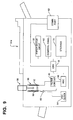
- FIG. 6 illustrates a printer 54 including the ink cartridge 10 in accordance with the present invention.
- the printer 54 has a processor 56 connected to various printer subsystems such as a paper motor drive 58 and printer control panel 60.
- the printer 54 is typically connected to a host computer (not shown) through a communication port 62.
- the host computer sends, via the communications port 62, jobs for printing.
- the printer 54 sends, via the communications port 62, various status messages including ink levels of cartridges within the printer.
- the printer 54 includes a clock 64 for providing the sense signal to the cartridge 10.
- the sense signal from the clock 64 may be controlled by a switch 66.
- a logical AND gate may be used as the switch 66.
- the other input to the switch (AND gate) 66 may be a control signal from the processor 56.
- the processor 56 controls when the sense signal is applied to the cartridge 10.
- the sense signal is applied to the first electrode 16 when ink level measurements are being performed.
- the printer 54 includes the filter circuit 40, which is connected to the second electrode 18 of the cartridge 10.
- An ADC 68 receives the filtered signal and converts it to a digital signal.
- the processor 56 reads the digital value and converts it to ink level measurement.
- the lookup table 72 may be stored within a storage 70 that is accessible by the processor 56.
- the values for the lookup table 72 may be predetermined via experimental or other methods.
- the storage 70 may be ROM, RAM, magnetic disk, or any suitable machine-readable media including a combination of two or more types of such media.
- the lookup table 72 may be a correlation table or a coefficient table. For a correlation table, the first column may list signal values and the second column may list corresponding fluid level. For a coefficient table, the first column may list signal values and the second column may list corresponding coefficient values to be used in calculating the fluid level.
- the lookup table 72 may be placed within memory 15 attached to the cartridge 10.
- Such memory 15 is usually programmable and can be read by the printer once the cartridge 10 is installed.
- Memory chips can be programmed with information relating the predicted ink level response of the printer's circuitry for that specific cartridge.
- the memory chips can include the lookup table, which would allow a processor to determine ink level from the digital signal values. In this way, the particular design of the cartridge 10 may be changed to suit engineering or market needs and the printer will be able to continue to accurately detect ink levels of varying ink cartridges.
- the printer 54 may include a remote ink supply 11, which is remote to the cartridge 10.
- the remote ink supply 11 may contain a larger supply of ink than the cartridge 10. When the ink within the cartridge 10 falls below a predetermined level, the remote ink supply 11 may be used to refill the cartridge 10 (a refill mechanism is not shown in Figure 6).
- the remote ink supply 11 may also include a first electrode 11 a for receiving the sense signal and a second electrode 11 b for receiving the detected signal. Although connections to the electrodes 11a and 11b of the remote ink supply 11 are not shown in Figure 6, the electrodes 11a and 11b may be connected in the same manner as the electrodes 16 and 18 of the cartridge 10.
- the remote ink supply 11 may also include memory 11c for holding lookup tables and other information.
- the printer 54 may send the ink level measurement to a computer connected to the printer 54 via the communications port 62.
- the ink level measurement may be sent when, for instance, the ink level is below a predetermined threshold.
- the host computer may request the ink level measurement each time a print job is sent to the printer 54 from the host computer.
- the host computer may monitor the ink level during a print job to ensure a successful completion of the print job.
- Ink level information may be made available via the control panel 60.
- a user may demand an ink level measurement using the control panel 60.
- a precise ink level measurement is displayed by the control panel 60.
- the control panel 60 may be used to display a warning message. The warning message may appear whether or not link level status was requested.
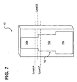
- Figure 7 shows the first electrode 16 on a first side of the cartridge 10 and the second electrode (not shown) on an opposite (second) side of the cartridge 10.
- the second electrode may have the same configuration as the first electrode.
- the first electrode 16 is not uniform in width, but has portions of differing widths.
- the first electrode 16 has top, middle and bottom portions 16a, 16b and 16c.
- the top portion 16a is narrowest, and the bottom portion 16b is widest.
- the portions having different widths define different areas. This design has several advantages. When the ink is low, the ink level detection system is most sensitive and accurate (because the bottom portion 16c is widest, or have larger relative area).
- abrupt changes in the measurement can be used to determine exact level of the fluid in the reservoir 13.
- the ink level falls from Level A to Level B
- the change in the detected signal is abrupt.
- Such abrupt changes can be recognized by the processor 56 to detect the exact level of the ink in the reservoir since the precise location of the change in the width of the electrodes is known.
- Electrolysis between the electrodes 16 and 18 and the ink can be minimized, without the dielectric tape 19a and 19b, by selecting a sufficiently high frequency signal as sensing signal utilized for the present invention.
- the sense signal may be an AC signal or a DC square wave signal.
- the specific frequency may be chosen with relatively broad latitude; however, choosing a frequency where both the resistive and capacitive properties contribute can maximize sensitivity of the detection system. That is where the current-voltage phase angle difference is around 45 degrees.
- Figure 8A shows a cartridge 10d in which electrodes 16d and 18d are built into, or embedded within, walls of a reservoir housing 12d.
- Figure 8B shows a cartridge 10e in which the electrodes 16e and 18e are placed outside reservoir housing 12e.
- Figure 9 illustrates an appliance 54a having an ink cartridge receptacle 86 for an ink reservoir 88.
- the appliance 54a may also include many of the same the components 40, 56, 58, 60, 62, 64, 66, 68 and 70 as the printer 54 of Figure 6.
- a first electrode 90 may be placed on a first side of interior of the receptacle 86, and a second electrode 92 may be placed on a second side of the interior of the receptacle 86.
- the electrodes 90 and 92 may be embedded within the walls of the receptacle 86. Because the electrodes 90 and 92 are a part of the receptacle 86, they may be used to detect other fault conditions such as a condition where the reservoir is not installed.
- the present invention may be implemented as an ink jet cartridge, ink reservoir, remote ink supply, and a printing system or appliance with improved reservoir receptacle.
- the present invention may be implemented in other contexts.
- the present invention may be implemented as an apparatus measuring fluid level within a canister containing beverage, syrup, or other food or chemicals.
Abstract
Description
- The present invention relates generally to ink jet printers. More particularly, the present invention relates to ink level sensing for printers utilizing ink jet cartridges and ink reservoirs.
- An operational consideration for printers utilizing ink reservoirs and cartridges is the level of ink in the cartridges. Sensing the ink level is performed so that the printer does not attempt to print without ink. Operation of ink jet and other types of printers without ink can damage the printer's print head.
- In thermal ink jet printers, printing is performed by boiling ink and shooting the ink through very small nozzles hundreds or even thousands of times per second. Printing without the ink, the print head - a complex electro-mechanical system containing hundreds of nozzles, heating elements, barriers, ink flow channels, and underlying circuits - would be irreparably damaged.
- In the past, printing without ink was not a pressing concern because useful life of the print heads was short. By the time the ink was depleted, the print head usually needed to be replaced. After depletion of the ink, the entire cartridge, including the print head, was discarded. Thus, the old ink jet cartridges were built as disposable units.
- More recently, however, the print heads are being built as reusable units. The print heads are able to last beyond the depletion of the ink. Because the print head is relatively expensive as compared to the ink, it is becoming increasingly common to replenish the ink rather than to discard the print head. For this reason, printing without ink should be avoided so as to avoid damaging the print head.
- Additionally, operation of a printer with a depleted ink supply may lead to loss of important information. For example, a printer printing a facsimile message may receive the transmitted information and operate as if the received information is being printed. If the ink is depleted, the information is never printed. Unless the receiver can ask the sender to retransmit the fax, the information is irretrievable.
- Knowing the exact ink level of the ink cartridge may be important under other considerations. For instance, before beginning a large print job, it would be useful to know whether the remaining ink is sufficient to finish the print job. If the amount of ink is insufficient, the ink cartridge can be replaced or replenished to avoid wasting time, paper, and effort of unsuccessfully attempting to print the large print job.
- The ink level of foam-filled ink containers may be sensed by measuring the opacity of an open area within the foam. The measurement is made with a light source and a photodetector. The ink level is sensed at only one location within the reservoir. Therefore, ink level above or below the sensing point cannot be determined. Additionally, this optical technique depends upon the ink level changing within the foam in a known manner, and gives erroneous readings in some circumstances. For example, a partially full cartridge stored for some time on its side may provide erroneous readings.
- There is a need to detect the level of ink remaining in the ink reservoir.
- According to one aspect of the invention, an ink cartridge for a printer includes a housing defining an ink reservoir; a first electrode proximal to the reservoir; and a second electrode proximal to the reservoir. The electrodes are spaced apart for ink level measurement of the reservoir.
- Other aspects and advantages of the present invention will become apparent from the following detailed description, taken in conjunction with the accompanying drawings, illustrating by way of example the principles of the present invention.
-
- Figure 1 is a sectional view of an ink cartridge in accordance with a preferred embodiment of the present invention;
- Figure 2 is an illustration of a representative circuit for demonstrating electrical characteristics of a fluid reservoir;
- Figure 3 is a flowchart of a method of measuring ink level in accordance with the present invention;
- Figure 4 is an illustration of a filter circuit in accordance with a preferred embodiment of the present invention;
- Figure 5 is a plot of percent ink level verses digital signal value of a sample ink cartridge;
- Figure 6 is an illustration of a printer including the ink cartridge;
- Figure 7 is a sectional view of an alternative embodiment of an ink cartridge in accordance with the present invention;
- Figure 8A is a sectional view of another embodiment of an ink cartridge in accordance with the present invention;
- Figure 8B is a sectional view of yet another embodiment of an ink cartridge in accordance with the present invention; and
- Figure 9 is an illustration of a printer having a fluid reservoir receptacle in accordance with the present invention.
-
- As shown in the drawings for purposes of illustration, the present invention is embodied in a method of and apparatus for detecting the level of ink remaining in an ink jet cartridge. If the ink level is found to be very low, operation of the printer can be halted to prevent damage to the print head. The ink level measurement can also be used to determine the remaining lifetime of the ink, thus allowing for prudent scheduling of print jobs. Additionally, measuring the ink level of the cartridge can prevent loss of valuable information.
- Referring to Figure 1, an
ink jet cartridge 10 includes ahousing 12 and aprint head 14. Thehousing 12 defines areservoir 13 for ink. The ink may be liquid, solid, or foam-filled. Afirst electrode 16 is located against a first side of thehousing 12 and asecond electrode 18 is located against a second side of thehousing 12. The second side may be the opposite the first side. Theelectrodes electrodes electrodes housing 12 as conductive paint. In experiments, electrodes of 0.5 mils think have been used successfully. Further, theelectrodes reservoir 13 to the bottom of thereservoir 13. In this configuration, the reservoir's ink level may be measured from full to empty. Otherwise, there is little, if any, restrictions on the size or the shape of theelectrodes -
Dielectric material electrodes coverings electrodes reservoir 13 and prevent electrolysis or other chemical reactions between the ink and theelectrodes dielectric material dielectric material dielectric material dielectric coverings cartridge 10 may includememory 15 for holding lookup tables and other information. Thememory 15 and lookup tables are discussed further below. - A sense signal is applied to the
first electrode 16, and a signal is detected at thesecond electrode 18. The detected signal is different than the sense signal applied to thefirst electrode 16 due to various factors. For example, the sense signal travels the distance between thefirst electrode 16 and thesecond electrode 18. Depending upon the electrical properties of the dielectric 19a and 19b, the dielectric 19a and 19b and theelectrodes reservoir 13. The ink of the reservoir may be characterized as presenting Resistance-Capacitance ("RC") circuits to the sense signal. - Figure 2 illustrates electrical characteristics of the
ink reservoir 13 of theink cartridge 10. Theink jet cartridge 10 can be analogized as a RC circuit. A capacitance formed between thefirst electrode 16 and its covering dielectric 19a is represented by afirst capacitor 20a. Another capacitance formed between thesecond electrode 18 and its covering dielectric 19b is represented by asecond capacitor 20b. The ink provides resistance, as represented by aresistor 22. The ink in thereservoir 13 also provides capacitance that is represented by acapacitor 24. - The
resistor 22 and thecapacitors ink reservoir 13 and are provided merely to illustrate the electrical properties within theink reservoir 13. Theresistor 22 and thecapacitors resistor 22 increases. - The resistance of the ink reduces the current flow between the
electrodes electrodes capacitors electrodes - The resistances and capacitance of the
ink jet cartridge 10 depend upon various factors. These factors include, but are not limited to, the following: the topology of the reservoir; the inherent electrical characteristic of the ink contained therein; the size and the shape of theelectrodes 1 6 and 18; the material from which theelectrodes cartridge 10. - When the ink is depleted, the
reservoir 13 acts as an open circuit with theresistor 22 having theoretically an infinite value and thecapacitors reservoir 13 has the lowest resistance and the highest capacitance. The exact, numerical value for the "lowest resistance value" of theresistor 22 and the exact, numerical value for the "highest capacitance value" of thecapacitors - Figure 3 is a
flowchart 26 illustrating the steps for measuring the ink level of thereservoir 13. When a measurement of the ink level is desired, the sense signal is applied to thefirst electrode 16. This step is represented byblock 28. - The sense signal may be applied by an oscillator connected to the
first electrode 16. In the preferred embodiment, the oscillator may include a clock circuit commonly found in most printers and other electronic devices. Such clock circuits typically produce a square-wave DC signal at a predetermined frequency. Thus, a square-wave DC signal may be used as the sense signal. Alternatively, an AC signal may be used as the sense signal. The sense signal is detected at the second electrode 18 (block 30) and the detected signal is converted to an ink level measurement (block 32). During conversion, the detected signal is filtered by a filter circuit into a filtered signal (block 34). The filtered signal is then converted to a digital signal (block 36). This is typically performed using an analog-to-digital converter (ADC). Finally, the value of the digital signal is used to determine the ink level (block 38). - The conversion of the digital signal value to the fluid level measurement may be performed at least two different ways. The digital signal value may be converted to the fluid level by using a correlation table. The correlation table would list signal values within the range of expected digital signal values, and it would relate each of the listed signal values to a fluid level.
- Alternatively, the fluid level may be determined by calculating a fluid level using coefficient values from a coefficient table. In this implementation, the digital signal value is correlated to a set of coefficients using a coefficient table. The coefficient table would list signal values within the range of expected digital signal values, and it would relate each of the listed signal values to a set of coefficients to be used for the calculation of the fluid level. The correlation table and the coefficient table are referred to generically as a "lookup table." The coefficients would probably be different for each design of the reservoir. The equation depends upon, at minimum, the geometry and size of the reservoir and the electrodes, and also depends upon the type of fluid used.
- The ink level measurement may be performed continuously or periodically. The period of time between the measurements may vary from less than a second to several minutes or even hours. Many factors are considered to determine the period of time between the measurements including, without limitation, size of the cartridge, rate of the usage, activities of the printer, etc. Also, the period of time between the measurements may vary in accordance with the ink level. For example, the ink level may be measured more often when the ink level falls below a predetermined threshold such as ten percent of capacity.
- Figure 4 illustrates a
filter circuit 40 for filtering the detected signal. Thefilter circuit 40 is a simple low pass filter that may be implemented in many different configurations. A preferred embodiment of thefilter circuit 40 includes acurrent sense resistor 42 connected between thesecond electrode 18 and ground. Adiode 44 is connected between thecurrent sense resistor 42 and avoltage sense capacitor 46. Thevoltage sense capacitor 46 is connected between thediode 44 and ground. The current component of the detected signal appears as a sense voltage across thecurrent sense resistor 42. This sense voltage is rectified by thediode 44, and the peak value appears across thevoltage sense capacitor 46. Thus, theresistor 42, thediode 44, and thecapacitor 46 work together to attenuate AC components of the detected signal. The remaining DC voltage component of the detected signal is the filtered signal. - The filtered signal may not be linearly related to the ink level as indicated by the data curve 52 of Figure 5. Figure 5 illustrates percent ink level verses digital signal value of an experimental ink cartridge. An X-axis of the diagram 50 indicates digital signal values. An Y-axis of the diagram 50 indicates percent ink level within the experimental ink cartridge's reservoir. An 8-bit analog-to-digital converter ("ADC") can produce digital signal values ranging from 0 to 255. The data curve 52 shows that when the
ink cartridge 10 is full, a digital signal value of about 220 is produced from the detected signal. The data curve 52 also shows that the digital signal value is zero when theink cartridge 10 is empty. - Figure 5 shows that, for a given change in percent ink level, change in digital signal values at low ink levels is larger compared to change in the digital signal values at high ink levels. This increased sensitivity at low ink levels provides for increased accuracy at low ink levels. This is desirable because accuracy at low ink levels is more useful in the process of determining whether or not to refill or replace the reservoir.
- Figure 6 illustrates a
printer 54 including theink cartridge 10 in accordance with the present invention. Theprinter 54 has aprocessor 56 connected to various printer subsystems such as apaper motor drive 58 andprinter control panel 60. Theprinter 54 is typically connected to a host computer (not shown) through acommunication port 62. The host computer sends, via thecommunications port 62, jobs for printing. Theprinter 54 sends, via thecommunications port 62, various status messages including ink levels of cartridges within the printer. - The
printer 54 includes aclock 64 for providing the sense signal to thecartridge 10. The sense signal from theclock 64 may be controlled by aswitch 66. A logical AND gate may be used as theswitch 66. The other input to the switch (AND gate) 66 may be a control signal from theprocessor 56. Using theswitch 66, theprocessor 56 controls when the sense signal is applied to thecartridge 10. The sense signal is applied to thefirst electrode 16 when ink level measurements are being performed. - The
printer 54 includes thefilter circuit 40, which is connected to thesecond electrode 18 of thecartridge 10. AnADC 68 receives the filtered signal and converts it to a digital signal. Theprocessor 56 reads the digital value and converts it to ink level measurement. - As discussed above, the conversion of the digital signal value to the ink level measurement may be performed by using a lookup table 32. The lookup table 72 may be stored within a
storage 70 that is accessible by theprocessor 56. The values for the lookup table 72 may be predetermined via experimental or other methods. Thestorage 70 may be ROM, RAM, magnetic disk, or any suitable machine-readable media including a combination of two or more types of such media. The lookup table 72 may be a correlation table or a coefficient table. For a correlation table, the first column may list signal values and the second column may list corresponding fluid level. For a coefficient table, the first column may list signal values and the second column may list corresponding coefficient values to be used in calculating the fluid level. - Alternatively, the lookup table 72 may be placed within
memory 15 attached to thecartridge 10.Such memory 15 is usually programmable and can be read by the printer once thecartridge 10 is installed. Memory chips can be programmed with information relating the predicted ink level response of the printer's circuitry for that specific cartridge. For instance, the memory chips can include the lookup table, which would allow a processor to determine ink level from the digital signal values. In this way, the particular design of thecartridge 10 may be changed to suit engineering or market needs and the printer will be able to continue to accurately detect ink levels of varying ink cartridges. - The
printer 54 may include aremote ink supply 11, which is remote to thecartridge 10. Theremote ink supply 11 may contain a larger supply of ink than thecartridge 10. When the ink within thecartridge 10 falls below a predetermined level, theremote ink supply 11 may be used to refill the cartridge 10 (a refill mechanism is not shown in Figure 6). Theremote ink supply 11 may also include afirst electrode 11 a for receiving the sense signal and asecond electrode 11 b for receiving the detected signal. Although connections to theelectrodes remote ink supply 11 are not shown in Figure 6, theelectrodes electrodes cartridge 10. Theremote ink supply 11 may also includememory 11c for holding lookup tables and other information. - The
printer 54 may send the ink level measurement to a computer connected to theprinter 54 via thecommunications port 62. The ink level measurement may be sent when, for instance, the ink level is below a predetermined threshold. Alternatively, the host computer may request the ink level measurement each time a print job is sent to theprinter 54 from the host computer. The host computer may monitor the ink level during a print job to ensure a successful completion of the print job. - Ink level information may be made available via the
control panel 60. A user may demand an ink level measurement using thecontrol panel 60. In response, a precise ink level measurement is displayed by thecontrol panel 60. When the ink level is below a predetermined threshold, thecontrol panel 60 may be used to display a warning message. The warning message may appear whether or not link level status was requested. - Figure 7 shows the
first electrode 16 on a first side of thecartridge 10 and the second electrode (not shown) on an opposite (second) side of thecartridge 10. The second electrode may have the same configuration as the first electrode. Thefirst electrode 16 is not uniform in width, but has portions of differing widths. Thefirst electrode 16 has top, middle andbottom portions top portion 16a is narrowest, and thebottom portion 16b is widest. The portions having different widths define different areas. This design has several advantages. When the ink is low, the ink level detection system is most sensitive and accurate (because thebottom portion 16c is widest, or have larger relative area). - Moreover, abrupt changes in the measurement can be used to determine exact level of the fluid in the
reservoir 13. When the ink level falls from Level A to Level B, there would be a relatively proportional change in the detected signal. However, when the ink level falls from Level B to Level C, the change in the detected signal is abrupt. Such abrupt changes can be recognized by theprocessor 56 to detect the exact level of the ink in the reservoir since the precise location of the change in the width of the electrodes is known. - Although specific embodiments have been described and illustrated, the invention is not limited to the specific forms of arrangements of parts so described and illustrated.
- For example, use of the
dielectric coverings electrodes dielectric tape - The sense signal may be an AC signal or a DC square wave signal. The specific frequency may be chosen with relatively broad latitude; however, choosing a frequency where both the resistive and capacitive properties contribute can maximize sensitivity of the detection system. That is where the current-voltage phase angle difference is around 45 degrees.
- Figure 8A shows a
cartridge 10d in whichelectrodes reservoir housing 12d. Figure 8B shows acartridge 10e in which theelectrodes reservoir housing 12e. - Figure 9 illustrates an
appliance 54a having anink cartridge receptacle 86 for anink reservoir 88. Theappliance 54a may also include many of the same thecomponents printer 54 of Figure 6. Afirst electrode 90 may be placed on a first side of interior of thereceptacle 86, and asecond electrode 92 may be placed on a second side of the interior of thereceptacle 86. In an alternative implementation, theelectrodes receptacle 86. Because theelectrodes receptacle 86, they may be used to detect other fault conditions such as a condition where the reservoir is not installed. - The present invention may be implemented as an ink jet cartridge, ink reservoir, remote ink supply, and a printing system or appliance with improved reservoir receptacle. However, the present invention may be implemented in other contexts. For example, the present invention may be implemented as an apparatus measuring fluid level within a canister containing beverage, syrup, or other food or chemicals.
- Accordingly, the present invention is not limited to the embodiments described above. Instead, the present invention is construed according to the claims that follow.
Claims (6)
- A printer (54) comprising:a fluid reservoir (13);a first electrode (16) placed proximal to a first side of the reservoir (13);a second electrode (18) placed proximal to a second side of the reservoir (13), the second side being opposite the first side.an oscillator (64) for providing a sense signal to the first electrode (16); anda filtering circuit (40) for removing ac content from a signal detected at the second electrode (18).
- The printer recited in claim 1 wherein the oscillator (64) is a system clock, and wherein the sense signal is a square wave DC signal.
- The printer recited in claim 1 further comprising a processor (56) for converting the filtered signal to an ink level measurement.
- The printer recited in claim 3 further comprising storage (70) encoded with a lookup table (72); and wherein the processor (56) uses the lookup table (72) to correlate filtered signal values to ink level measurements.
- The printer recited in claim 1, wherein the reservoir (13) is contained within an ink cartridge (10, 10d, 10e).
- The printer recited in claim 1 wherein the reservoir is contained within a receptacle (86)
Applications Claiming Priority (2)
| Application Number | Priority Date | Filing Date | Title |
|---|---|---|---|
| US502360 | 2000-02-14 | ||
| US09/502,360 US6431670B1 (en) | 2000-02-14 | 2000-02-14 | Ink level sensing method and apparatus |
Publications (2)
| Publication Number | Publication Date |
|---|---|
| EP1125748A1 true EP1125748A1 (en) | 2001-08-22 |
| EP1125748B1 EP1125748B1 (en) | 2005-04-06 |
Family
ID=23997454
Family Applications (1)
| Application Number | Title | Priority Date | Filing Date |
|---|---|---|---|
| EP01300733A Expired - Lifetime EP1125748B1 (en) | 2000-02-14 | 2001-01-29 | Ink level sensing method and apparatus |
Country Status (8)
| Country | Link |
|---|---|
| US (1) | US6431670B1 (en) |
| EP (1) | EP1125748B1 (en) |
| JP (1) | JP2001253088A (en) |
| KR (1) | KR100712788B1 (en) |
| CN (1) | CN1225361C (en) |
| DE (1) | DE60109833T2 (en) |
| HK (1) | HK1039978B (en) |
| TW (1) | TW553841B (en) |
Cited By (10)
| Publication number | Priority date | Publication date | Assignee | Title |
|---|---|---|---|---|
| WO2004008082A2 (en) * | 2002-07-10 | 2004-01-22 | Olivetti I-Jet S.P.A. | System for detecting the level of liquid in a tank |
| EP1502750A1 (en) * | 2003-07-30 | 2005-02-02 | Hewlett-Packard Development Company, L.P. | Printing device having a printing fluid detector |
| EP1457340A3 (en) * | 2003-03-11 | 2005-03-23 | Brother Kogyo Kabushiki Kaisha | Ink package and ink detecting apparatus |
| WO2007012455A1 (en) * | 2005-07-27 | 2007-02-01 | Brita Gmbh | Measuring device and conductivity measuring device for determining flow capacities of electroconductive liquids, measuring element, and method |
| US7547082B2 (en) | 2005-07-05 | 2009-06-16 | Samsung Electronics Co., Ltd. | Ink cartridge including a unit to sense a remaining amount of ink |
| US8171802B2 (en) | 2008-03-28 | 2012-05-08 | Brita Gmbh | Method for measuring the volume flow of electrically conductive liquids through a vessel |
| CN102700257A (en) * | 2012-01-10 | 2012-10-03 | 珠海并洲贸易有限公司 | Ink cartridge, ink quantity prompting and early warning method for same, ink cartridge chip and imaging device |
| FR3043198A1 (en) * | 2015-11-04 | 2017-05-05 | Dover Europe Sarl | DEVICE FOR MEASURING LEVEL IN A RESERVOIR |
| US9701128B2 (en) | 2014-10-22 | 2017-07-11 | Dover Europe Sàrl | Device for measuring a level in a tank |
| WO2018067133A1 (en) * | 2016-10-05 | 2018-04-12 | Hewlett-Packard Development Company, L.P. | Printing fluid cartridge with electrodes and method to the level of fluid in a printing fluid cartridge |
Families Citing this family (46)
| Publication number | Priority date | Publication date | Assignee | Title |
|---|---|---|---|---|
| EP1369788A3 (en) * | 2002-06-04 | 2007-07-04 | Bayer HealthCare LLC | RS232C interface system |
| US6789864B2 (en) * | 2002-08-13 | 2004-09-14 | Hewlett-Packard Development Company, L.P. | Systems and methods for refilling printing cartridges |
| US6962078B2 (en) * | 2002-12-24 | 2005-11-08 | Lexmark International, Inc. | Liquid level detection gauge and associated methods |
| US6848762B2 (en) * | 2003-04-25 | 2005-02-01 | Hewlett-Packard Development Company, L.P. | Ink level sensing |
| JP2005053110A (en) * | 2003-08-05 | 2005-03-03 | Canon Inc | Ink tank, recorder, and monitoring system of quantity of ink used |
| JP4054742B2 (en) * | 2003-09-29 | 2008-03-05 | キヤノン株式会社 | Ink supply system and recording apparatus |
| JP4289963B2 (en) * | 2003-09-29 | 2009-07-01 | キヤノン株式会社 | Ink tank and recording device |
| US7013804B2 (en) * | 2003-12-16 | 2006-03-21 | Lexmark International, Inc. | Method of ink level determination for multiple ink chambers |
| US7234787B2 (en) * | 2004-01-08 | 2007-06-26 | Eastman Kodak Company | Liquid level detection method and apparatus |
| TWI235520B (en) * | 2004-09-10 | 2005-07-01 | Antig Tech Co Ltd | Device for measuring fuel capacity in fuel cell system |
| CN101065251B (en) | 2004-11-30 | 2012-08-29 | 泛达公司 | Market-based labeling system and method |
| KR100694154B1 (en) * | 2005-10-04 | 2007-03-12 | 삼성전자주식회사 | Ink level detecting apparatus of ink-jet printer |
| JP4144637B2 (en) | 2005-12-26 | 2008-09-03 | セイコーエプソン株式会社 | Printing material container, substrate, printing apparatus, and method for preparing printing material container |
| JP5119823B2 (en) * | 2007-09-19 | 2013-01-16 | セイコーエプソン株式会社 | Information transmission system for electronic equipment, media processing device, and control method for media processing device |
| CN101883682B (en) * | 2007-12-10 | 2012-10-10 | 株式会社理光 | Imager forming apparatus and foam application device |
| JP5566829B2 (en) * | 2010-09-16 | 2014-08-06 | 武蔵エンジニアリング株式会社 | Liquid automatic supply mechanism and coating apparatus provided with the same |
| WO2012102701A1 (en) | 2011-01-25 | 2012-08-02 | Hewlett-Packard Development Company, L.P. | Capacitive fluid level sensing |
| US8491111B2 (en) * | 2011-02-28 | 2013-07-23 | Funai Electric Co., Ltd. | Consumable supply item with capacitive fluid level detection for micro-fluid applications |
| CN102248800B (en) * | 2011-05-16 | 2013-03-13 | 珠海天威技术开发有限公司 | Method for testing ink box of ink-jet printer |
| JP5884296B2 (en) * | 2011-05-20 | 2016-03-15 | セイコーエプソン株式会社 | LIQUID CONTAINER, LIQUID EJECTING DEVICE PROVIDED WITH LIQUID CONTAINER, AND METHOD FOR PRODUCING LIQUID CONTAINER |
| JP2013202898A (en) * | 2012-03-28 | 2013-10-07 | Seiko Epson Corp | Printing device, and method for controlling the same |
| US9744773B2 (en) | 2014-04-22 | 2017-08-29 | Hewlett-Packard Development Company, L.P. | Detecting ink characteristics |
| WO2017018973A1 (en) | 2015-07-24 | 2017-02-02 | Hewlett-Packard Development Company, L.P. | Sensing a property and level of a fluid |
| EP3337663B1 (en) * | 2015-11-10 | 2020-05-06 | Hewlett-Packard Development Company, L.P. | Printhead-integrated ink level sensor with central clearing resistor |
| EP3448688B1 (en) * | 2016-04-29 | 2021-03-24 | Hewlett-Packard Development Company, L.P. | Printing apparatus and methods for detecting fluid levels |
| US10960658B2 (en) | 2016-07-11 | 2021-03-30 | Hewlett-Packard Development Company, L.P. | Detecting a level of printable fluid in a container |
| US10576748B2 (en) | 2016-10-07 | 2020-03-03 | Hewlett-Packard Development Company, L.P. | Fluid reservoir with fluid property and level detection |
| WO2018169514A1 (en) * | 2017-03-14 | 2018-09-20 | Hewlett-Packard Development Company, L.P. | Liquid level sensor circuit |
| JP2018179858A (en) * | 2017-04-18 | 2018-11-15 | ローム株式会社 | Water level sensor and toilet device |
| CN114644314B (en) * | 2017-05-03 | 2024-04-05 | 耐普罗公司 | Apparatus, system and method for providing a liquid level monitor |
| US11487864B2 (en) | 2017-10-18 | 2022-11-01 | Hewlett-Packard Development Company, L.P. | Print apparatus component authentication |
| CN111201144A (en) | 2017-10-18 | 2020-05-26 | 惠普发展公司,有限责任合伙企业 | Fluid property sensor |
| CN111183037B (en) | 2017-10-18 | 2021-07-06 | 惠普发展公司,有限责任合伙企业 | Replaceable printing device and method for verifying authenticity of replaceable printing device |
| DE102017223855A1 (en) * | 2017-12-28 | 2019-07-04 | Kautex Textron Gmbh & Co. Kg | Operating fluid tank with integrated system for the detection of the filling level |
| EP3681723B1 (en) | 2018-12-03 | 2021-07-28 | Hewlett-Packard Development Company, L.P. | Logic circuitry |
| EP3687815B1 (en) | 2018-12-03 | 2021-11-10 | Hewlett-Packard Development Company, L.P. | Logic circuitry |
| US10894423B2 (en) | 2018-12-03 | 2021-01-19 | Hewlett-Packard Development Company, L.P. | Logic circuitry |
| ES2955564T3 (en) | 2018-12-03 | 2023-12-04 | Hewlett Packard Development Co | Logic circuit system |
| KR20210087982A (en) | 2018-12-03 | 2021-07-13 | 휴렛-팩커드 디벨롭먼트 컴퍼니, 엘.피. | logic circuit |
| WO2020117197A1 (en) | 2018-12-03 | 2020-06-11 | Hewlett-Packard Development Company, L.P. | Logic circuitry |
| CN113168457A (en) | 2018-12-03 | 2021-07-23 | 惠普发展公司,有限责任合伙企业 | Logic circuitry packaging |
| KR20210087980A (en) | 2018-12-03 | 2021-07-13 | 휴렛-팩커드 디벨롭먼트 컴퍼니, 엘.피. | logic circuit |
| WO2021080607A1 (en) | 2019-10-25 | 2021-04-29 | Hewlett-Packard Development Company, L.P. | Logic circuitry package |
| CN113168454A (en) | 2018-12-03 | 2021-07-23 | 惠普发展公司,有限责任合伙企业 | Logic circuitry packaging |
| US11338586B2 (en) | 2018-12-03 | 2022-05-24 | Hewlett-Packard Development Company, L.P. | Logic circuitry |
| JP7284936B2 (en) * | 2019-07-31 | 2023-06-01 | 株式会社リコー | Powder recovery device and image forming device |
Citations (5)
| Publication number | Priority date | Publication date | Assignee | Title |
|---|---|---|---|---|
| US5682184A (en) * | 1995-12-18 | 1997-10-28 | Xerox Corporation | System for sensing ink level and type of ink for an ink jet printer |
| US5719556A (en) * | 1995-05-22 | 1998-02-17 | Albin; Robert | Liquid level sensor utilizing AC and resistance |
| JPH10119301A (en) * | 1996-10-18 | 1998-05-12 | Brother Ind Ltd | Ink residue detector |
| FR2769708A1 (en) * | 1997-10-10 | 1999-04-16 | Canon Kk | Determining quantity of ink in reservoir of ink jet printer |
| US6106087A (en) * | 1996-10-01 | 2000-08-22 | Brother Kogyo Kabushiki Kaisha | Detection apparatus for detecting residual ink quantity in ink cartridge |
Family Cites Families (6)
| Publication number | Priority date | Publication date | Assignee | Title |
|---|---|---|---|---|
| US5757390A (en) * | 1992-08-12 | 1998-05-26 | Hewlett-Packard Company | Ink volume sensing and replenishing system |
| CA2128676C (en) * | 1993-09-08 | 1997-12-23 | John D. Sotack | Capacitive sensor |
| IT1272076B (en) * | 1993-12-16 | 1997-06-11 | Olivetti Canon Ind Spa | INK LEVEL MEASURING DEVICE OF A PRINTING MODULE INK JET |
| US6010210A (en) * | 1997-06-04 | 2000-01-04 | Hewlett-Packard Company | Ink container having a multiple function chassis |
| FR2765331B1 (en) * | 1997-06-27 | 1999-10-01 | Canon Kk | PROCEDURE AND DEVICE FOR DETERMINING THE QUANTITIES OF CONSUMABLE PRODUCTS CONTAINED IN TANKS GROUPED SIDE BY THE OTHERS AND DEVICE FOR PRINTING DOCUMENTS IMPLEMENTING THIS PROCESS |
| FR2765332A1 (en) * | 1997-06-27 | 1998-12-31 | Canon Kk | METHOD AND DEVICE FOR DETECTION OF A FILLING THRESHOLD OF AN ELECTRICALLY INSULATING TANK CONTAINING AN ELECTRICALLY CONDUCTIVE PRODUCT, FOR EXAMPLE PRINTING INK |
-
2000
- 2000-02-14 US US09/502,360 patent/US6431670B1/en not_active Expired - Lifetime
- 2000-08-31 TW TW089117802A patent/TW553841B/en not_active IP Right Cessation
- 2000-11-14 CN CNB001309382A patent/CN1225361C/en not_active Expired - Fee Related
-
2001
- 2001-01-29 DE DE60109833T patent/DE60109833T2/en not_active Expired - Lifetime
- 2001-01-29 EP EP01300733A patent/EP1125748B1/en not_active Expired - Lifetime
- 2001-02-13 KR KR1020010006893A patent/KR100712788B1/en not_active IP Right Cessation
- 2001-02-14 JP JP2001036450A patent/JP2001253088A/en active Pending
-
2002
- 2002-02-19 HK HK02101202.0A patent/HK1039978B/en not_active IP Right Cessation
Patent Citations (5)
| Publication number | Priority date | Publication date | Assignee | Title |
|---|---|---|---|---|
| US5719556A (en) * | 1995-05-22 | 1998-02-17 | Albin; Robert | Liquid level sensor utilizing AC and resistance |
| US5682184A (en) * | 1995-12-18 | 1997-10-28 | Xerox Corporation | System for sensing ink level and type of ink for an ink jet printer |
| US6106087A (en) * | 1996-10-01 | 2000-08-22 | Brother Kogyo Kabushiki Kaisha | Detection apparatus for detecting residual ink quantity in ink cartridge |
| JPH10119301A (en) * | 1996-10-18 | 1998-05-12 | Brother Ind Ltd | Ink residue detector |
| FR2769708A1 (en) * | 1997-10-10 | 1999-04-16 | Canon Kk | Determining quantity of ink in reservoir of ink jet printer |
Non-Patent Citations (1)
| Title |
|---|
| PATENT ABSTRACTS OF JAPAN vol. 1998, no. 10 31 August 1998 (1998-08-31) * |
Cited By (21)
| Publication number | Priority date | Publication date | Assignee | Title |
|---|---|---|---|---|
| US7370528B2 (en) | 2002-07-10 | 2008-05-13 | Telecom Italia S.P.A. | System for detecting the level of liquid in a tank |
| WO2004008082A3 (en) * | 2002-07-10 | 2004-03-18 | Olivetti I Jet Spa | System for detecting the level of liquid in a tank |
| WO2004008082A2 (en) * | 2002-07-10 | 2004-01-22 | Olivetti I-Jet S.P.A. | System for detecting the level of liquid in a tank |
| US7249506B2 (en) | 2002-07-10 | 2007-07-31 | Telecom Italia S.P.A. | System for detecting the level of liquid in a tank |
| EP1457340A3 (en) * | 2003-03-11 | 2005-03-23 | Brother Kogyo Kabushiki Kaisha | Ink package and ink detecting apparatus |
| US7185975B2 (en) | 2003-03-11 | 2007-03-06 | Brother Kogyo Kabushiki Kaisha | Ink detecting apparatus and ink package |
| EP1787818A1 (en) * | 2003-03-11 | 2007-05-23 | Brother Kogyo Kabushiki Kaisha | Ink package and ink detecting apparatus |
| EP1502750A1 (en) * | 2003-07-30 | 2005-02-02 | Hewlett-Packard Development Company, L.P. | Printing device having a printing fluid detector |
| US7185960B2 (en) | 2003-07-30 | 2007-03-06 | Hewlett-Packard Development Company, L.P. | Printing device having a printing fluid detector |
| US7547082B2 (en) | 2005-07-05 | 2009-06-16 | Samsung Electronics Co., Ltd. | Ink cartridge including a unit to sense a remaining amount of ink |
| WO2007012455A1 (en) * | 2005-07-27 | 2007-02-01 | Brita Gmbh | Measuring device and conductivity measuring device for determining flow capacities of electroconductive liquids, measuring element, and method |
| US7905144B2 (en) | 2005-07-27 | 2011-03-15 | Brita Gmbh | Measuring device, and conductivity measuring device, for determining flow capacities of electroconductive liquids, measuring element, and method |
| US8171802B2 (en) | 2008-03-28 | 2012-05-08 | Brita Gmbh | Method for measuring the volume flow of electrically conductive liquids through a vessel |
| CN102700257A (en) * | 2012-01-10 | 2012-10-03 | 珠海并洲贸易有限公司 | Ink cartridge, ink quantity prompting and early warning method for same, ink cartridge chip and imaging device |
| CN102700257B (en) * | 2012-01-10 | 2015-10-14 | 珠海艾派克微电子有限公司 | Ink quantity of ink prompting and method for early warning, ink box chip, print cartridge and imaging device |
| US9701128B2 (en) | 2014-10-22 | 2017-07-11 | Dover Europe Sàrl | Device for measuring a level in a tank |
| FR3043198A1 (en) * | 2015-11-04 | 2017-05-05 | Dover Europe Sarl | DEVICE FOR MEASURING LEVEL IN A RESERVOIR |
| EP3165882A1 (en) * | 2015-11-04 | 2017-05-10 | Dover Europe Sàrl | Device for level measurement in a reservoir |
| US10086618B2 (en) | 2015-11-04 | 2018-10-02 | Dover Europe Sarl | Device for level measurement in a reservoir |
| WO2018067133A1 (en) * | 2016-10-05 | 2018-04-12 | Hewlett-Packard Development Company, L.P. | Printing fluid cartridge with electrodes and method to the level of fluid in a printing fluid cartridge |
| US10836178B2 (en) | 2016-10-05 | 2020-11-17 | Hewlett Packard Develpment Company, L.P. | Printing fluid cartridge with electrodes and method to the level of fluid in a printing fluid cartridge |
Also Published As
| Publication number | Publication date |
|---|---|
| DE60109833D1 (en) | 2005-05-12 |
| JP2001253088A (en) | 2001-09-18 |
| KR20010082146A (en) | 2001-08-29 |
| US6431670B1 (en) | 2002-08-13 |
| TW553841B (en) | 2003-09-21 |
| EP1125748B1 (en) | 2005-04-06 |
| CN1309293A (en) | 2001-08-22 |
| DE60109833T2 (en) | 2006-01-19 |
| HK1039978A1 (en) | 2002-05-17 |
| CN1225361C (en) | 2005-11-02 |
| KR100712788B1 (en) | 2007-05-02 |
| HK1039978B (en) | 2006-07-28 |
Similar Documents
| Publication | Publication Date | Title |
|---|---|---|
| EP1125748B1 (en) | Ink level sensing method and apparatus | |
| US6345532B1 (en) | Method and device for determining the quantity of product present in a reservoir, a product reservoir and a device for processing electrical signals intended for such a determination device | |
| US5682184A (en) | System for sensing ink level and type of ink for an ink jet printer | |
| US6866359B2 (en) | Ink jet printhead quality management system and method | |
| EP0509747B1 (en) | Ink detecting device for a liquid-ink printing element | |
| US6099101A (en) | Disabling refill and reuse of an ink jet print head | |
| JP2009196366A (en) | Apparatus controlled by data from consumable parts with incorporated memory device | |
| JPH06191056A (en) | Method and device for recognizing exhaustion of ink in ink jet printing head | |
| US20040032442A1 (en) | Systems and methods for refilling printing cartridges | |
| EP1493586B1 (en) | Printing device having a printing fluid detector | |
| JP2003291367A (en) | Device for displaying remaining amount of liquid | |
| US6254212B1 (en) | Method and device for determining the quantity of product present in a reservoir, notably that of ink present in an image forming device | |
| EP0551014A2 (en) | Ink jet recording apparatus | |
| JP2007090558A (en) | Inkjet recording device and ink detection method of the device | |
| US20040218000A1 (en) | Printing device having a printing fluid detection system | |
| US20030231915A1 (en) | Coded ribbon cartridge, decoder, and ribbon ink capacity indicator with LCD display | |
| US6183054B1 (en) | Method and device for determining the quantities of consumable products contained in reservoirs grouped together next to one another and document printing device using this method | |
| US6325477B1 (en) | Method and device for determining the quantity of product present in a reservoir, a product reservoir and a device for processing electrical signals intended for such a determination device | |
| JPH1123349A (en) | Apparatus and method for determining amount of consumed material, printer apparatus, business equipment, computer readable memory, and detecting apparatus | |
| US6172697B1 (en) | Method and apparatus for detecting the level of toner using a photosensor | |
| US20030128245A1 (en) | Method and apparatus for transferring information between a printer portion and a replaceable printing component | |
| US6361135B1 (en) | Method and device for determining the distribution of product present in a reservoir, notably ink in an image device | |
| WO2016018361A1 (en) | Printhead with temperature sensing memristor | |
| TW381170B (en) | Method and device for determining the quantity of product present in a reservoir, notably that of ink in an image forming device | |
| JP4470525B2 (en) | Container identification device and liquid ejection device having container identification function |
Legal Events
| Date | Code | Title | Description |
|---|---|---|---|
| PUAI | Public reference made under article 153(3) epc to a published international application that has entered the european phase |
Free format text: ORIGINAL CODE: 0009012 |
|
| AK | Designated contracting states |
Kind code of ref document: A1 Designated state(s): DE FR GB Kind code of ref document: A1 Designated state(s): AT BE CH CY DE DK ES FI FR GB GR IE IT LI LU MC NL PT SE TR |
|
| AX | Request for extension of the european patent |
Free format text: AL;LT;LV;MK;RO;SI |
|
| 17P | Request for examination filed |
Effective date: 20020129 |
|
| AKX | Designation fees paid |
Free format text: DE FR GB |
|
| GRAP | Despatch of communication of intention to grant a patent |
Free format text: ORIGINAL CODE: EPIDOSNIGR1 |
|
| GRAS | Grant fee paid |
Free format text: ORIGINAL CODE: EPIDOSNIGR3 |
|
| GRAA | (expected) grant |
Free format text: ORIGINAL CODE: 0009210 |
|
| AK | Designated contracting states |
Kind code of ref document: B1 Designated state(s): DE FR GB |
|
| REG | Reference to a national code |
Ref country code: GB Ref legal event code: FG4D |
|
| REF | Corresponds to: |
Ref document number: 60109833 Country of ref document: DE Date of ref document: 20050512 Kind code of ref document: P |
|
| PLBE | No opposition filed within time limit |
Free format text: ORIGINAL CODE: 0009261 |
|
| STAA | Information on the status of an ep patent application or granted ep patent |
Free format text: STATUS: NO OPPOSITION FILED WITHIN TIME LIMIT |
|
| ET | Fr: translation filed | ||
| 26N | No opposition filed |
Effective date: 20060110 |
|
| PGFP | Annual fee paid to national office [announced via postgrant information from national office to epo] |
Ref country code: FR Payment date: 20100205 Year of fee payment: 10 |
|
| PGFP | Annual fee paid to national office [announced via postgrant information from national office to epo] |
Ref country code: DE Payment date: 20100127 Year of fee payment: 10 Ref country code: GB Payment date: 20100125 Year of fee payment: 10 |
|
| GBPC | Gb: european patent ceased through non-payment of renewal fee |
Effective date: 20110129 |
|
| REG | Reference to a national code |
Ref country code: FR Ref legal event code: ST Effective date: 20110930 |
|
| PG25 | Lapsed in a contracting state [announced via postgrant information from national office to epo] |
Ref country code: FR Free format text: LAPSE BECAUSE OF NON-PAYMENT OF DUE FEES Effective date: 20110131 |
|
| PG25 | Lapsed in a contracting state [announced via postgrant information from national office to epo] |
Ref country code: GB Free format text: LAPSE BECAUSE OF NON-PAYMENT OF DUE FEES Effective date: 20110129 |
|
| REG | Reference to a national code |
Ref country code: DE Ref legal event code: R119 Ref document number: 60109833 Country of ref document: DE Effective date: 20110802 |
|
| PG25 | Lapsed in a contracting state [announced via postgrant information from national office to epo] |
Ref country code: DE Free format text: LAPSE BECAUSE OF NON-PAYMENT OF DUE FEES Effective date: 20110802 |