EP1126631A2 - Antenna diversity device with phase controlled summation of antenna signals - Google Patents
Antenna diversity device with phase controlled summation of antenna signals Download PDFInfo
- Publication number
- EP1126631A2 EP1126631A2 EP01101770A EP01101770A EP1126631A2 EP 1126631 A2 EP1126631 A2 EP 1126631A2 EP 01101770 A EP01101770 A EP 01101770A EP 01101770 A EP01101770 A EP 01101770A EP 1126631 A2 EP1126631 A2 EP 1126631A2
- Authority
- EP
- European Patent Office
- Prior art keywords
- signal
- phase
- fault
- antenna
- signals
- Prior art date
- Legal status (The legal status is an assumption and is not a legal conclusion. Google has not performed a legal analysis and makes no representation as to the accuracy of the status listed.)
- Granted
Links
Images


Classifications
-
- H—ELECTRICITY
- H04—ELECTRIC COMMUNICATION TECHNIQUE
- H04B—TRANSMISSION
- H04B7/00—Radio transmission systems, i.e. using radiation field
- H04B7/02—Diversity systems; Multi-antenna system, i.e. transmission or reception using multiple antennas
-
- H—ELECTRICITY
- H04—ELECTRIC COMMUNICATION TECHNIQUE
- H04B—TRANSMISSION
- H04B7/00—Radio transmission systems, i.e. using radiation field
- H04B7/02—Diversity systems; Multi-antenna system, i.e. transmission or reception using multiple antennas
- H04B7/04—Diversity systems; Multi-antenna system, i.e. transmission or reception using multiple antennas using two or more spaced independent antennas
- H04B7/08—Diversity systems; Multi-antenna system, i.e. transmission or reception using multiple antennas using two or more spaced independent antennas at the receiving station
- H04B7/0868—Hybrid systems, i.e. switching and combining
- H04B7/0874—Hybrid systems, i.e. switching and combining using subgroups of receive antennas
-
- H—ELECTRICITY
- H04—ELECTRIC COMMUNICATION TECHNIQUE
- H04B—TRANSMISSION
- H04B7/00—Radio transmission systems, i.e. using radiation field
- H04B7/02—Diversity systems; Multi-antenna system, i.e. transmission or reception using multiple antennas
- H04B7/04—Diversity systems; Multi-antenna system, i.e. transmission or reception using multiple antennas using two or more spaced independent antennas
- H04B7/08—Diversity systems; Multi-antenna system, i.e. transmission or reception using multiple antennas using two or more spaced independent antennas at the receiving station
- H04B7/0802—Diversity systems; Multi-antenna system, i.e. transmission or reception using multiple antennas using two or more spaced independent antennas at the receiving station using antenna selection
- H04B7/0805—Diversity systems; Multi-antenna system, i.e. transmission or reception using multiple antennas using two or more spaced independent antennas at the receiving station using antenna selection with single receiver and antenna switching
- H04B7/0814—Diversity systems; Multi-antenna system, i.e. transmission or reception using multiple antennas using two or more spaced independent antennas at the receiving station using antenna selection with single receiver and antenna switching based on current reception conditions, e.g. switching to different antenna when signal level is below threshold
-
- H—ELECTRICITY
- H04—ELECTRIC COMMUNICATION TECHNIQUE
- H04B—TRANSMISSION
- H04B7/00—Radio transmission systems, i.e. using radiation field
- H04B7/02—Diversity systems; Multi-antenna system, i.e. transmission or reception using multiple antennas
- H04B7/04—Diversity systems; Multi-antenna system, i.e. transmission or reception using multiple antennas using two or more spaced independent antennas
- H04B7/08—Diversity systems; Multi-antenna system, i.e. transmission or reception using multiple antennas using two or more spaced independent antennas at the receiving station
- H04B7/0837—Diversity systems; Multi-antenna system, i.e. transmission or reception using multiple antennas using two or more spaced independent antennas at the receiving station using pre-detection combining
- H04B7/084—Equal gain combining, only phase adjustments
-
- H—ELECTRICITY
- H04—ELECTRIC COMMUNICATION TECHNIQUE
- H04B—TRANSMISSION
- H04B7/00—Radio transmission systems, i.e. using radiation field
- H04B7/02—Diversity systems; Multi-antenna system, i.e. transmission or reception using multiple antennas
- H04B7/04—Diversity systems; Multi-antenna system, i.e. transmission or reception using multiple antennas using two or more spaced independent antennas
- H04B7/08—Diversity systems; Multi-antenna system, i.e. transmission or reception using multiple antennas using two or more spaced independent antennas at the receiving station
- H04B7/0802—Diversity systems; Multi-antenna system, i.e. transmission or reception using multiple antennas using two or more spaced independent antennas at the receiving station using antenna selection
- H04B7/0831—Compensation of the diversity switching process for non-uniform properties or faulty operations of the switches used in the diversity switching process
Definitions
- the invention relates to an antenna diversity system for receiving the frequency-modulated Broadcasting with phase controlled summation of antenna signals for vehicles with a Multi-antenna system with at least two antenna output signals and a receiving device with one input each for a first and a second received signal path, of which the second of the two received signal paths is controlled by a phase control device Contains phase rotator, at the output of the received signal the same phase has as in the first branch and the two received signals in phase in a summation element are summed and the summed signal is fed to frequency demodulation.
- Antenna diversity systems of this type are preferably used for VHF radio reception and have long been known, for example from US4079318 and from US Pat. No. 5,517,696. These diversity systems aim to achieve a larger useful signal by superimposing two or more antenna signals in phase than with a single antenna, so as to reduce the likelihood of level drops in the area with multipath propagation. This results in a more favorable signal-to-noise ratio on average in relation to the receiver noise in the sum signal.
- the flawless mode of operation of such an antenna diversity system is, however, limited to the fact that the partial waves (Rayleigh reception field) which overlap at the receiving location differ only slightly in their instantaneous frequency, so that there are no audible reception disturbances. In reception situations, such as those shown in Fig.
- the received partial waves are no longer of the same frequency and lead to frequency interference due to the overlay, which after frequency demodulation during the Driving often lead to spontaneous noise.
- the wave bundles with the different transit times overlap at the receiving location in accordance with a Rayleigh distribution, which has different effects on the different antennas on the vehicle, so that the antenna signals of two diversity antennas on the vehicle can also have different instantaneous frequencies, particularly in the area of level fading.
- the difference between these frequencies is caused by the frequency modulation of the high-frequency carrier and is usually very large and the resulting phase difference would have to be corrected by the phase shifter in the second signal path if the signal in the first signal path has no frequency interference.
- the object of the invention is therefore in an antenna diversity system according to the preamble of claim 1 to avoid these disadvantages, the number of effective antenna signals inexpensively increase and thereby improve diversity efficiency.
- a particularly important advantage that comes with the invention is the applicability of one Large number of antennas or antenna signals in the case of the limited number of phase-controlled ones Signal paths. This makes the probability of the occurrence of disturbed received signals drastically reduced.
- the extent of signal improvement achievable with the invention is explained in more detail below using an example.
- the necessary technical effort remains extremely low since it relies on electronic switching measures and intelligent Limited electronic circuits, which are inexpensive due to the highly integrated circuits can be used.
- this increase in system performance can be achieved without additional extremely complex frequency converters and phase locked loops.
- several phase-locked loops can only be adjusted with regard to their control properties difficult to control and complicate the system.
- the interference detector 18 in the present Invention as long as fault detection signals 38 are emitted after each switching operation, until the same and only undisturbed received signal is present at both inputs 31 and 32, which leads to an undisturbed summed signal 37 in the receiving device 4.
- Fig. 1 Reception situation in a wave field disturbed by multipath propagation.
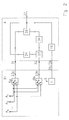
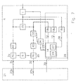
- Fig. 2 Antenna diversity system according to the invention with an antenna system with switching device 21, a receiving device 4 with signal path 1 31 and signal path 2 32 and a switching device 11, which all reception signals 23 simultaneously for both signal paths 31.32 can provide.
- a phase locked loop is located in the receiving device 4, consisting of a phase controller with low-pass character 34 and a phase shifter 33 for in-phase summation of the signals in the summation element 35.
- the summed output signal 37 is next to the FM receiver 1 on the one hand the phase controller with low-pass character 34 for phase control and the other a fault detector 18 for fast Fault detection fed in, so that with the fault detection signal 38 via switching device 11
- Another received signal 23 is assigned to at least one of the two signal paths 31, 32 becomes.
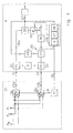
- Fig. 4 Arrangement as in Fig. 2 with signal summation in the intermediate frequency range according to Mixers 2 of the receiving device 4 controlled by the common oscillator 6 with a Signal evaluation processor 26, in which a fault detector 18, a timer 27 for detection the time intervals between occurring faults and a logic circuit 14 for control the switching device 11 and for switching from the phase mode to the scanning mode are included. Switching takes place by disconnecting one of the two signal paths with the signal path switch 16 and decommissioning the phase controller with low-pass character 34 through the phase control signal 25 in the event of excessive interference in the summed output signal 37 the system switches to a sufficiently low frequency of interference in the output signal 37 in the scanning mode back to live mode.
- phase mode is with the help of logic circuit 14 in the event of excessive interference in the summed output signal 37 switched to the scanning mode and in the signal path 31 a received signal 23a switched on with high priority from a priority list.
- the latter is in signal path 2 sequential switching on and checking the frequency of interference stored all available reception signal 23b stored in the logic circuit 14 and continuously updated.
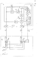
- Fig. 6 arrangement as in Fig. 5, but with a fault detector with better resolution 18b and accurate ranking of the received signals 23b in the priority list and a fault detector with extremely fast display 18a to avoid too long test times in the sum signal path 43 and the associated audible interference.
- Fig. 7 arrangement as in Fig. 6, but with two separate fault detectors with better Resolution 18b, c for the purpose of the permanent availability of the fault display signal 10 for Improved the priority list in scanning mode and improved display of the better Signals in phase mode.
- Fig. 8 Arrangement according to the invention with a receiving device 4, each with an I-frequency converter 44 and a Q frequency converter 45 in the two signal paths 1, 2 31,32 and summation elements 35 for the regression of the frequency-modulated signals in the Signal paths 1,2 31,32 and in the sum signal path 43 for fast detection of the disturbance analogue fault detectors 18.
- the phase shift is carried out by separate evaluation of the intermediate frequency I and Q signals in the phase rotator 33.
- the DSP 41 the Signals ⁇ Q and ⁇ I separately digitized and the phase shifter 33 from the phase controller with a low-pass character 34 preferably controlled digitally.
- the basic arrangement of a diversity antenna system according to the invention is shown in FIG. 2 shown.
- the receiving device 4 has a first signal path 31 and a second signal path 32, in which a phase rotator is switched on.
- transmission block 36 according to the prior art, the signal in the second received signal path with an auxiliary modulation acted upon, with the help of the phase rotating device 33 by a phase control device 34 is controlled such that at the output of the summation element 35 the signals in first reception path and in the second reception path are summed in phase.
- the Multi-antenna system 21 contains controllable switches 5, with the help of which, depending on the Switch positions of the controllable switches 5 signals 23a and 23b on the first 31 and the second 32 received signal path.
- this signal is a fault detector 18 to extremely quickly Detection of the sum signal disturbed by frequency interference stroke, its interference detection signal 38 in turn is fed to a controllable logic switching device 11 which is in the multi-antenna system 21 by choosing a different switching position Switches 5a and 5b receive another signal at at least one of the inputs 31 and 32, respectively supplies. The rapid switching of the switches 5a and 5b causes the phase-locked loop first comes out of step.
- phase control device 34 the character of a low-pass transfer function, i.e.
- the maximum phase change speed must be set so that it is also in the capture range the phase control can result in no audible frequency interference.
- the phase control speed must not be limited so that the speed during a trip phase changes resulting from the Rayleigh reception field of those undisturbed in the frequency swing Signals 23a and 23b of the phase locked loop of the required phase change in-phase superimposition of the signals in the summation element 35 can no longer follow.
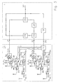
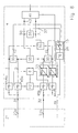
- FIG. 3 shows a more complex and generally designed multi-antenna system 21, with the help of switching impedances 7a to 7d using switches 8a to 8d the most varied signal pairs 23a and 23b are fed to the received signal paths 31 and 33, respectively become.
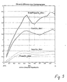
- the diversity efficiency is a pure one Scanning diversity systems with the same two antennas from the curve ScanDiv_2Ant.
- the curve labeled ScanDiv_4Ant in FIG. 9 describes the diversity efficiency of the four antennas extended and arranged in a line antenna group. From this it can be seen that by making several antennas available, the diversity efficiency increases significantly and almost reach the numerical number of antennas at sufficiently large distances can.
- the improvement that can be achieved with the device according to the present invention beyond the state of the art is described, for example, for the antenna group described in FIG. 9 by the one with ScanPhaseDiv_4 Ant.
- the diversity efficiency can be increased by the value 1.5 by using the invention.
- Similar improvements can also be achieved with 4 antennas arranged compactly on the window pane of a motor vehicle, whose different reception behavior, despite the proximity to one another, results from the different interaction with the vehicle body.
- due to the reduced disturbances in the summed output signal 37 there is a reduction in the switching frequency effective there and, as a result, a subjectively perceived quieter FM reception if the invention, as shown below, is advantageously designed.
- the desired improvement in the signal-to-noise ratio results from the in-phase superimposition of the useful signals in the two signal paths.
- the present invention can also be applied to all known diversity systems with phase control, that is to say to systems with maximum ratio control or very generally with control of the phase with regard to an optimum useful-to-noise ratio in the summed output signal 37, also with regard to adjacent channel and co-channel interference.
- the upper limit frequency for the phase control signal 25 has been found in existing systems about 50 Hz has proven to be favorable for reception in the FM radio range. So that is the control time TE is not less than approx. 20 ms.
- the present invention takes advantage of the fact that in the antenna system with switching device 21, a larger number than two received signals Are available. In reception areas with poor supply i.e. with a high frequency of interference in the individual antenna signals and thus also in each of two of these antenna signals The sum signal formed provides the in-phase summation of such signals practically none Advantage. Because in these areas there is between successive fault displays for the Loop does not settle enough time.
- Invention between the phase mode with the assignment of different antennas after the strategies described below and the pure scanning mode. If the antenna system is started in scanning mode, i.e. the signal path 2 in Fig. 4 by Opening of the signal path switch 16 is switched off, then the Phase controller with low-pass character 34 shut down and the FM receiver 1 receives at the output of the summation element 35 exclusively the received signal 23a. When a malfunction occurs in the summed output signal 37, an address signal 39 is generated via the logic circuit 14, which switches through another receiving signal 23a via the switching device 11.
- the activation time TA is as Criterion selected time TASP reached, the signal path 2 32 by closing the signal path switch 16 switched on, the phase controller with low-pass character 34 by release activated by the phase control signal 25 and thus the phase locked loop closed. Because of the phase-locked loop can test the sufficiently low frequency of faults, tested with the help of TA settle in. This settling can be done with any pair of available reception signals 23 take place. The optimal selection of the two signal paths 1,2 31,32 supplied Receive signals 23 from the available receive signals will be described below.
- the timer 27 activated and via the logic circuit 14 and the switching device 11 initially successively at least one of the received signals 23 replaced.
- the activation time becomes with each occurrence of the fault detection signal 38 TA determined for the switched pair of received signals 23.
- a predetermined activation time TAPS which is also preferably selected 5-10 times TE is.
- the arrangements in FIGS. 5 - 8 pursued a strategy in scanning mode in such a way that with the help of the switched off Signal path 2 by alternately switching on the available reception signals 23b the frequency of interference of the individual signals and a priority list in the logic circuit 14 with regard to the interference purity of the received signals 23b.
- the priority list is always updated before operating in scanning mode. If the TASP criterion for switching from scanning mode to phase mode is met, then according to the invention those signals are the signal paths 1 31 and 2 32 via the Switching device 11 assigned, which lead the priority list. The system can therefore use the best two signals in phase mode.
- the reception disturbances in the reception signals 23a and 23b are determined separately and when a fault occurs in the summed output signal 37 the worse of the two received signals 23a and 23b by another available one Receive signal 23 are exchanged. This exchange usually takes place entirely without disturbing the output signal 37.
- this method using the signal path selector 15, which is controlled by a clock generator 29 located in the logic circuit 14.
- the fault detector 18 alternately between the switching position 1 in the scanning mode and S for checking the received signal 23 in signal path 2 and the received signal 23 in summed output signal 37 switched by the clock 29.
- the clock 29 switches these signals each over a necessary test time to the fault detector 18, so that in the Logic circuit 14, an address signal 39 is sent, whereby on the one hand when there is a Disturbance in the summed output signal 37 there is a switchover of the received signal 23a and on the other hand, by checking the received signal 23b in the signal path 2, the priority list for the available reception signals 23 is updated.
- the signal path selector 15 which realizes as a fault detector with extremely fast display 18a is the elaborate use of several fault detectors 18 avoided. If the TASP criterion switches the system into phase mode and the two signal paths 31, 32 receive those reception signals 23 which have the highest or high priority updated in the list of logic circuit 14. In phase mode, the signal path selector 15 sequentially in each case over the necessary test time of the fault detector 18 the three switch positions, so that in this mode the frequency of interference both of the individual signals of the two signal paths and of the summed output signal 37 is present in the logic circuit 14. If a fault occurs in the summed output signal 37 the signal is then exchanged in the signal path, which has the greater frequency of interference owns. To avoid audible interference, the interference detection time of the interference detector should be used 18 should not be significantly larger than 50 ⁇ s.
- the test of the summed output signal 37 must with the necessary short test time with the help of the fault detector with extremely fast display 18a become. After switching the system into phase mode, the receive signals 23 in the two signal paths 1, 2 31, 32 sequentially by switching the signal path selector 15 checked.
- quadrature modulators are often used for frequency conversion used. 8 is in the receiving device, each with an I-frequency converter 44a, 44b and a Q frequency converter 45a, 45b, which are from a common oscillator 6 can be controlled and the control of the Q-frequency converter via a 90 ° phase shifter 42 takes place.
- the intermediate frequency I and Q signals are used in modern receiver concepts processed in a digital processor 41 (DSP). Because of the currently bit rate in such a processor may still be necessary extremely fast displaying fault detector 18 as an analog element and to be arranged in the analog range of the receiver.
- Obtaining the full frequency modulated intermediate frequency signal takes place in both signal paths 31, 32 with the aid of the summation elements 35, the outputs of which are connected to terminals 1 and 2 in signal path selector 15 are.
- a further summation element is used to form the summed output signal 37 35 available, in which the signals undI and the signals ⁇ Q are added and the Terminal S of the signal path selector 15 are supplied.
- the regulation of the phase in the signal path 2 32 is done by amplitude weighting elements 46a, 46b, which are preferably from the DSP 41 can be controlled to regulate the phase. Because of the relatively slow control processes the phase can also be set with a limited data rate of the DSP 41.
Abstract
Description
Die Erfindung betrifft eine Antennendiversityanlage zum Empfang des frequenzmodulierten Rundfunks mit phasengeregelter Summation von Antennensignalen für Fahrzeuge mit einer Mehrantennenanlage mit mindestens zwei Antennenausgangssignalen und einer Empfangseinrichtung mit je einem Eingang für einen ersten und einen zweiten Empfangssignalpfad, von denen der zweite der beiden Empfangssignalpfade eine durch eine Phasenregeleinrichtung gesteuerte Phasendreheinrichtung enthält, an deren Ausgang das Empfangssignal die gleiche Phase besitzt wie im ersten Zweig und die beiden Empfangssignale in einem Summationsglied phasengleich summiert sind und das summierte Signal der Frequenzdemodulation zugeführt ist.The invention relates to an antenna diversity system for receiving the frequency-modulated Broadcasting with phase controlled summation of antenna signals for vehicles with a Multi-antenna system with at least two antenna output signals and a receiving device with one input each for a first and a second received signal path, of which the second of the two received signal paths is controlled by a phase control device Contains phase rotator, at the output of the received signal the same phase has as in the first branch and the two received signals in phase in a summation element are summed and the summed signal is fed to frequency demodulation.
Antennendiversityanlagen dieser Art werden bevorzugt für den UKW-Rundfunkempfang eingesetzt und sind seit langem bekannt, z.B. aus der US4079318 sowie aus dem US-Patent 5,517,696. Diese Diversitysysteme zielen darauf ab, durch gleichphasige Überlagerung zweier oder auch mehrerer Antennensignale ein größeres Nutzsignal zu erzielen als mit einer Einzelantenne, um so im Gebiet mit Mehrwegeausbreitung die Wahrscheinlichkeit von Pegeleinbrüchen zu reduzieren. Damit ergibt sich im Summensignal ein in Bezug auf das Empfängerrauschen im Mittel günstigeres Signalrauschverhältnis. Die einwandfreie Wirkungsweise einer derartigen Antennendiversityanlage ist jedoch darauf beschränkt, dass die am Empfangsort sich überlagernden Teilwellen (Rayleigh-Empfangsfeld) sich in ihrer Momentanfrequenz nur unwesentlich unterscheiden, so dass sich daraus keine hörbaren Empfangsstörungen ergeben. In Empfangssituationen, wie sie z.B. in Fig. 1 dargestellt sind, bei denen sich Wellenbündel mit unterschiedlichen Laufzeiten τ0 bis τ3 am Empfangsort überlagern, sind die empfangenen Teilwellen nicht mehr gleichfrequent und führen durch die Überlagerung zu Frequenzstörhüben, die nach der Frequenzdemodulation während der Fahrt häufig zu spontan auftretenden Störgeräuschen führen. Die Wellenbündel mit den unterschiedlichen Laufzeiten überlagern sich am Empfangsort jeweils nach Maßgabe einer Rayleigh-Verteilung, welche sich bei den unterschiedlichen Antennen am Fahrzeug unterschiedlich auswirkt, so dass auch die Antennensignale zweier Diversityantennen am Fahrzeug insbesondere im Bereich des Pegelfadings unterschiedliche Momentanfrequenz besitzen können. Die Differenz dieser Frequenzen ist durch die Frequenzmodulation des hochfrequenten Trägers bedingt und ist in der Regel sehr groß und der daraus resultierende Phasenunterschied müsste von dem Phasendrehglied im zweiten Signalpfad ausgeregelt werden, wenn das Signal im ersten Signalpfad keinen Frequenzstörhub besitzt. Andererseits würde bei schneller Phasenregelung ein auf dem ersten Signalpfad gestörtes Signal durch den Regelvorgang seine Störung auf den zweiten Signalpfad aufprägen und somit die Störung im Summensignal erzwingen. Ein weiterer Nachteil dieses Systems ist die Begrenzung auf zwei Antennensignale, so dass keine ausreichende diversitätsmäßige Wirkung mit diesem System zu erzielen ist. Auf ähnliche Weise wirken Nachbarkanalstörungen aufgrund einer begrenzten Selektion in der Zwischenfrequenzebene. Auch durch Intermodulation anderer UKW-Sender im Empfangskanal auftretende Signale bewirken in Verbindung mit Pegeleinbrüchen Frequenzhubstörungen auf dem Nutzsignal, welche mit dem Phasenregelsystem nicht eliminiert werden können.Antenna diversity systems of this type are preferably used for VHF radio reception and have long been known, for example from US4079318 and from US Pat. No. 5,517,696. These diversity systems aim to achieve a larger useful signal by superimposing two or more antenna signals in phase than with a single antenna, so as to reduce the likelihood of level drops in the area with multipath propagation. This results in a more favorable signal-to-noise ratio on average in relation to the receiver noise in the sum signal. The flawless mode of operation of such an antenna diversity system is, however, limited to the fact that the partial waves (Rayleigh reception field) which overlap at the receiving location differ only slightly in their instantaneous frequency, so that there are no audible reception disturbances. In reception situations, such as those shown in Fig. 1, in which wave bundles with different transit times τ 0 to τ 3 overlap at the receiving location, the received partial waves are no longer of the same frequency and lead to frequency interference due to the overlay, which after frequency demodulation during the Driving often lead to spontaneous noise. The wave bundles with the different transit times overlap at the receiving location in accordance with a Rayleigh distribution, which has different effects on the different antennas on the vehicle, so that the antenna signals of two diversity antennas on the vehicle can also have different instantaneous frequencies, particularly in the area of level fading. The difference between these frequencies is caused by the frequency modulation of the high-frequency carrier and is usually very large and the resulting phase difference would have to be corrected by the phase shifter in the second signal path if the signal in the first signal path has no frequency interference. On the other hand, in the case of rapid phase control, a signal disturbed on the first signal path would impress its disturbance on the second signal path through the control process and thus force the disturbance in the sum signal. Another disadvantage of this system is the limitation to two antenna signals, so that a sufficient diversity effect cannot be achieved with this system. Adjacent channel interference acts in a similar way due to a limited selection in the intermediate frequency level. Signals occurring in the receiving channel through intermodulation of other FM transmitters, in conjunction with level drops, also cause frequency swing disturbances on the useful signal, which cannot be eliminated with the phase control system.
Aufgabe der Erfindung ist es deshalb bei einer Antennendiversityanlage nach dem Oberbegriff
des Anspruchs 1, diese Nachteile zu vermeiden, kostengünstig die Anzahl der wirksamen Antennensignale
zu erhöhen und dadurch die Diversity-Effizienz zu verbessern.The object of the invention is therefore in an antenna diversity system according to the preamble
of
Diese Aufgabe wird erfindungsgemäß durch den kennzeichnenden Teil des Anspruchs 1 gelöst.This object is achieved by the characterizing part of
Ein besonders wichtiger Vorteil, der mit der Erfindung einhergeht, ist die Einsetzbarkeit einer
Vielzahl von Antennen bzw. Antennensignalen bei der auf zwei begrenzten Anzahl von phasengesteuerten
Signalpfaden. Dadurch wird die Wahrscheinlichkeit für das Auftreten gestörter Empfangssignale
drastisch reduziert. Das Ausmaß der mit der Erfindung erreichbaren Signalverbesserung
wird weiter unten anhand eines Beispiel näher erläutert. Der notwendige technische Aufwand
bleibt dabei äußerst gering, da er sich auf elektronische Umschaltmaßnahmen und intelligente
Elektronikschaltungen beschränkt, welche infolge der hochintegrierten Schaltungen preiswert
eingesetzt werden können. Vorteilhafterweise kann diese Leistungssteigerung des Systems
ohne zusätzliche äußerst aufwendige Frequenzumsetzer und Phasenregelkreise erreicht werden.
Darüber hinaus lassen sich mehrere Phasenregelkreise hinsichtlich ihrer Regeleigenschaften nur
schwer beherrschen und komplizieren das System zusätzlich. Selbst für den Fall, dass zumindest
ein Antennensignal unter den verfügbaren ungestört ist wird der Störungsdetektor 18 in der vorliegenden
Erfindung solange Störungserkennungssignale 38 nach jedem Umschaltvorgang abgeben,
bis an beiden Eingängen 31 und 32 dasselbe und einzige ungestörte Empfangssignal vorliegt,
welches in der Empfangseinrichtung 4 zu einem ungestörten summierten Signal 37 führt.A particularly important advantage that comes with the invention is the applicability of one
Large number of antennas or antenna signals in the case of the limited number of phase-controlled ones
Signal paths. This makes the probability of the occurrence of disturbed received signals
drastically reduced. The extent of signal improvement achievable with the invention
is explained in more detail below using an example. The necessary technical effort
remains extremely low since it relies on electronic switching measures and intelligent
Limited electronic circuits, which are inexpensive due to the highly integrated circuits
can be used. Advantageously, this increase in system performance
can be achieved without additional extremely complex frequency converters and phase locked loops.
In addition, several phase-locked loops can only be adjusted with regard to their control properties
difficult to control and complicate the system. Even in the event that at least
an antenna signal among those available is undisturbed, the
Fig. 1: Empfangssituation in einem durch Mehrwegeausbreitung gestörten Wellenfeld.Fig. 1: Reception situation in a wave field disturbed by multipath propagation.
Fig. 2: Antennendiversityanlage nach der Erfindung mit einer Antennenanlage mit Schalteinrichtung
21, einer Empfangseinrichtung 4 mit dem Signalpfad 1 31 und Signalpfad 2 32 und
einer Schalteinrichtung 11, welche alle Empfangssignale 23 gleichzeitig für beide Signalpfade
31,32 zur Verfügung stellen kann. In der Empfangseinrichtung 4 befindet sich ein Phasenregelkreis,
bestehend aus einem Phasenregler mit Tiefpaß-Charakter 34 und einem Phasendrehglied
33 zur gleichphasigen Summation der Signale im Summationsglied 35. Das summiertes Ausgangssignal
37 ist neben dem FM-Empfänger 1 zum einen dem Phasenregler mit Tiefpaß-Charakter
34 zur Phasenregelung und zum anderen einem Störungsdetektor 18 zur schnellen
Störerkennung zugeleitet, so dass mit dem Störerkennungssignal 38 über Schalteinrichtung 11
mindestens einem der beiden Signalpfade 31,32 ein anderes Empfangssignal 23 zugewiesen
wird.Fig. 2: Antenna diversity system according to the invention with an antenna system with
Fig. 3: Anordnung wie in Fig. 2, jedoch mit komplexer Antennenanlage mit Schalteinrichtung 21
zur Erzeugung zusätzlicher unterschiedlicher Antennensignale durch mit Schaltern 8 wechselweise
über Auswahlschalter 5 angeschaltete, beispielsweis einseitig mit der Masse 3 verbundene
Blindwiderstände 7.3: Arrangement as in FIG. 2, but with a complex antenna system with
Fig. 4: Anordnung wie in Fig. 2 mit Signalsummation im Zwischenfrequenzbereich nach den
vom gemeinsamen Oszillator 6 angesteuerten Mischern 2 der Empfangseinrichtung 4 mit einem
Signalbewertungsprozessor 26, in welchem ein Störungsdetektor 18, ein Zeitglied 27 zur Feststellung
der Zeitabstände zwischen auftretenden Störungen und eine Logikschaltung 14 zur Ansteuerung
der Schalteinrichtung 11 und zur Umschaltung vom Phasen-Modus auf den Scanning-Modus
enthalten sind. Die Umschaltung erfolgt durch Auftrennung eines der beiden Signalpfad
mit dem Signalpfadschalter 16 und Stillegung des Phasenreglers mit Tiefpaß -Charakter 34 durch
das Phasenstellsignal 25 bei zu großer Störhäufigkeit im summierten Ausgangssignal 37. Bei
hinreichend geringer Störhäufigkeit im Ausgangssignal 37 im Scanning-Modus schaltet das System
zurück in den Phasen-Modus.Fig. 4: Arrangement as in Fig. 2 with signal summation in the intermediate frequency range according to
Fig. 5: Anordnung wie in Fig. 4, jedoch mit einem durch das Taktsignal 24 getakteten Signalpfadselektor
15 zur getrennten Prüfung sowohl der Signale in den beiden Signalpfaden 31,32 als
auch des summierten Ausgangssignals 37 am Ausgang des Summationsglieds 35. Im Phasen-Modus
wird mit Hilfe der Logikschaltung 14 bei zu großer Störhäufigkeit im summierten Ausgangssignal
37 auf den Scanning-Modus umgeschaltet und im Signalpfad 31 ein Empfangssignal
23a mit hoher Priorität aus einer Prioritätsliste angeschaltet. Letztere wird im Signalpfad 2 durch
sequentielles Anschalten und Prüfen der Störhäufigkeit abgelegt aller verfügbarer Empfangssignal
23b in der Logikschaltung 14 abgelegt und laufend aktualisiert. Bei der Umschaltung in
den Phasen-Modus werden zunächst die beiden besten aller verfügbaren Empfangssignale 23
gemäß der Prioritätsliste den Signalpfaden 31,32 zugewiesen; bei weiteren Störungen im sümmierten
Ausgangssignal 37 wird stets das schlechtere der beiden Empfangssignale 23 durch ein
anderes ersetzt.5: Arrangement as in FIG. 4, but with a signal path selector clocked by the
Fig. 6: Anordnung wie in Fig. 5, jedoch mit einem Störungsdetektor mit besserer Auflösung 18b
und treffsicherer Reihung der Empfangssignale 23b in der Prioritätenliste und einem Störungsdetektor
mit extrem schneller Anzeige 18a zur Vermeidung zu langer Prüfzeiten im Summensignalpfad
43 und der damit verbundenen hörbaren Störung.Fig. 6: arrangement as in Fig. 5, but with a fault detector with
Fig. 7: Anordnung wie in Fig. 6, jedoch mit zwei getrennten Störungsdetektoren mit besserer
Auflösung 18b,c zum Zwecke der permanenten Verfügbarkeit des Störungsanzeigesignals 10 zur
Verbesserung der Prioritätenliste im Scanning-Modus und zur verbesserten Anzeige des besseren
Signals im Phasen-Modus.Fig. 7: arrangement as in Fig. 6, but with two separate fault detectors with
Fig. 8: Anordnung nach der Erfindung mit einer Empfangseinrichtung 4 mit jeweils einem I-Frequenzumsetzer
44 und einem einem Q-Frequenzumsetzer 45 in den beiden Signalpfaden 1,2
31,32 und Summationsgliedern 35 für die Rückbildung der frequenzmodulierten Signale in den
Signalpfaden 1,2 31,32 und im Summensignalpfad 43 zur schnellen Detektion der Störung mit
analog arbeitenden Störungsdetektoren 18. Die Phasendrehung erfolgt durch getrennte Bewertung
der zwischenfrequenten I- und Q-Signale im Phasendrehglied 33. Im DSP 41 werden die
Signale ΣQ und ΣI getrennt digitalisiert und das Phasendrehglied 33 vom Phasenregler mit Tiefpaß-Charakter
34 vorzugsweise digital angesteuert.Fig. 8: Arrangement according to the invention with a
Fig. 9: Diversity-Effizienz einer linearen Antennengruppe in Abhängigkeit von dem auf die
Wellenlänge bezogenen Abstand zwischen den Elementen für folgende Fälle:
Die grundsätzliche Anordung einer Diversityantennenanlage nach der Erfindung ist in Fig. 2
dargestellt. Die Empfangseinrichtung 4 besitzt einen ersten Signalpfad 31 und einen zweiten Signalpfad
32, in dem eine Phasendreheinrichtung eingeschaltet ist. Im Übertragungsblock 36 wird
nach dem Stand der Technik das Signal im zweiten Empfangssignalpfad mit einer Hilfsmodulation
beaufschlagt, mit dessen Hilfe die Phasendreheinrichtung 33 durch eine Phasenregeleinrichtung
34 derart angesteuert ist, dass am Ausgang des Summationsgliedes 35 die Signale im
ersten Empfangspfad und im zweiten Empfangspfad gleichphasig summiert sind. In der
Mehrantennenanlage 21 sind steuerbare Schalter 5 enthalten, mit deren Hilfe abhängig von den
Schaltstellungen der steuerbaren Schalter 5 jeweils Signale 23a bzw. 23b an den ersten 31 und
den zweiten 32 Empfangssignalpfad geführt sind. Somit werden jeweils zwei dieser Antennensignale
mit Hilfe der Empfangssignalpfade gleichphasig summiert, wobei diese Summation sowohl
in der Ebene des hochfrequenten Eingangssignals als auch in der Zwischenfrequenzebene
erfolgen kann.The basic arrangement of a diversity antenna system according to the invention is shown in FIG. 2
shown. The
Um die von der Phasendreheinrichtung 33 nicht ausregelbaren Frequenzhubstörungen im summierten
Signal 37 zu vermeiden, wird dieses Signal einem Störungsdetektor 18 zur extrem raschen
Erkennung des durch Frequenzstörhub gestörten Summensignals zugeführt, dessen Störungserkennungssignal
38 wiederum einer steuerbaren logischen Schalteinrichtung 11 zugeführt
ist, welche in der Mehrantennenanlage 21 durch Wahl einer unterschiedlichen Schaltstellung der
Schalter 5a bzw. 5b an mindestens einem der Eingänge 31 bzw. 32 ein anderes Empfangssignal
liefert. Das rasche Weiterschalten der Schalter 5a bzw. 5b bewirkt, dass der Phasenregelkreis
zunächst außer Tritt kommt. In order to sum the frequency swing disturbances which cannot be compensated by the
Um sicherzustellen, dass sich durch das erneute Einschwingen des Phasenregelkreises durch die
Phasendreheinrichtung 33 keine zu schnellen Phasenänderungen ergeben, deren zeitliche Ableitung
einen hörbaren Frequenzstörhub erzeugen würde, ist es deshalb erfindungsgemäß notwendig,
der Phasenregeleinrichtung 34 den Charakter einer Tiefpaßübertragungsfunktion zu geben,
d.h. die maximale Phasenänderungsgeschwindigkeit ist so einzustellen, dass sich auch im Fangbereich
der Phasenregelung keine hörbaren Frequenzstörhübe dabei ergeben können. Andererseits
darf die Phasenregelgeschwindigkeit nicht so begrenzt werden, dass die bei einer Fahrt
durch das Rayleigh-Empfangsfeld sich ergebenden Phasenänderungen von im Frequenzhub ungestörten
Signalen 23a und 23b der Phasenregelkreis der erforderlichen Phasenänderung zur
gleichphasigen Überlagerung der Signale im Summationsglied 35 nicht mehr folgen kann. Hierfür
sind Zeitkonstanten in der Größenordnung von 1 bis 20 msec zweckmäßig. Während der Einschwingzeit
des Regelkreises für das neue Paar von Antennensignalen entstehen dann keine zusätzlichen
Störungen, sondern das Zeitverhalten des Signals 37 ist während dieser Zeit vergleichbar
mit dem Empfang im Rayleigh-Empfangsfeld. Auch für den Grenzfall, dass die Phasenregeleinrichtung
nicht einschwingen kann, wird somit aufgrund der Signalüberwachung mit
Hilfe des Störungsdetektors 18 mit Hilfe der Vielzahl von Antennen für ein störungsfreies Signal
37 gesorgt.To make sure that the phase lock loop starts to settle again
In Fig. 3 ist eine komplexere und allgemeiner ausgestaltete Mehrantennenanlage 21 dargestellt,
mit deren Hilfe durch Umschaltung von Impedanzen 7a bis 7d mit Hilfe der Schalter 8a bis 8d
die unterschiedlichsten Signalpaare 23a bzw. 23b den Empfangssignalpfaden 31 bzw. 33 zugeführt
werden.3 shows a more complex and generally designed
Mit Diversitysystemen erreicht man eine erhebliche Verbesserung der Empfangsqualität. Diese ergibt sich aus der Diversity-Effizienz, die sich wiederum aus der Reduzierung der Störhäufigkeit durch das Diversitysystem ermitteln läßt. Hierbei ist die Diversity-Effizienz n als die äquivalente Anzahl voneinander unabhängiger, d.h. dekorrelierter Antennensignale definiert. Bezeichnet man die in einem einzelnen Antennensignal auftretende Störwahrscheinlichkeit mit pe, dann ist die im Empfänger des Diversitysystems mit der Diversity-Effizienz n auftretende Störwahrscheinlichkeit pd = pe n. Mit dieser Definition können verschiedene Systeme hinsichtlich ihrer Leistungsfähigkeit miteinander verglichen werden. Die Diversity-Effizienz n mehrerer Diversitysysteme ist für das Beispiel von bis zu vier im relativen Abstand drel voneinander in einer Linie positionierten Antennen mit Rundstrahlcharakteristik in Abhängigkeit von drel = Abstand/λ in Fig. 9 für den sehr häufig auftretenden Fall von Gleich- bzw. Nachbar-kanalstörungen gegenübergestellt.With diversity systems you can achieve a significant improvement in reception quality. This results from the diversity efficiency, which in turn can be determined from the reduction in the frequency of interference by the diversity system. Here, the diversity efficiency n is defined as the equivalent number of independent, ie decorrelated, antenna signals. If the interference probability occurring in a single antenna signal is denoted by p e , then the interference probability occurring in the receiver of the diversity system with diversity efficiency n is p d = p e n . With this definition different systems can be compared in terms of their performance. The diversity efficiency n of several diversity systems is for the example of up to four antennas positioned at a relative distance drel from one another in a line with omnidirectional characteristics as a function of drel = distance / λ in FIG. 9 for the very frequently occurring case of equal or Neighboring channel interference compared.
Würde man z.B. das System in Fig. 2 bei abgeschaltetem Störungsdetektor 18, also nach dem
Stand der Technik ausschließlich mit Phasenregelung betreiben und wären die beiden Empfangssignale
23 von zwei im Abstand drel positionierten Antennen mit Rundcharakteristik fest aufgeschaltet,
so ergäbe sich die als PhaseDiv_2Ant gekennzeichnete Kurve für die daraus resultierende
Diversity-Effizienz in Fig. 9. Im Vergleich hierzu geht die Diversity-Effizienz eines reinen
Scanning-Diversitysytems mit denselben beiden Antennen aus der Kurve ScanDiv_2Ant hervor.
Die mit ScanDiv_4Ant bezeichnete Kurve in Fig. 9 beschreibt die Diversity-Effizienz der auf
vier Antennen erweiterten und in einer Linie angeordneten Antennengruppe. Daraus ist ersichtlich,
dass durch die zur Verfügungstellung mehrerer Antennen die Diversity-Effizienz stark ansteigt
und bei hinreichend großen Abständen nahezu die nummerische Anzahl der Antennen erreichen
kann.Would you e.g. the system in Fig. 2 with the
Die Verbesserung, die sich mit der gemäß der vorliegenden Erfindung über den Stand der Technik
hinaus erreichen läßt, ist z.B. für die beschriebene Antennengruppe in Fig. 9 durch die mit
ScanPhaseDiv_4 Ant beschrieben. Je nach Abstand zwischen den Einzelstrahlern der Antennengruppe
läßt sich im vorgegebenen Beispiel im reinen 4-Antennen-Scanning-Betrieb durch Anwendung
der Erfindung die Diversity-Effizienz um den Wert 1,5 steigern. Aufgrund des exponentiellen
Gesetzes pd = pe n würde sich bei einer Fehlerwahrscheinlichkeit von pe = 0,1 die
Fehlerwahrscheinlichkeit für das erfindungsgemäße Antennensystem ausgehend vom reinen
Scanning-Betrieb um den weiteren Faktor von pe 1,5 = 0,03 reduzieren. Ähnliche Verbesserungen
lassen sich auch mit 4 kompakt auf der Fensterscheibe eines Kraftfahrzeugs angeordneten Antennen
erreichen, deren unterschiedliches Empfangsverhalten trotz der Nähe zueinander aus dem
unterschiedlichen Zusammenwirken mit der Fahrzeugkarosserie resultiert. Hinzu kommt aufgrund
der reduziert auftretenden Störungen im summierten Ausgangssignal 37 eine Reduzierung
der dort wirksamen Schalthäufigkeit und in der Folge ein subjektiv empfundener ruhigerer
UKW-Empfang, wenn die Erfindung, wie im folgenden gezeigt, vorteilhaft ausgestaltet wird.
Ferner ergibt sich im Phasenmodus jeweils die erwünschte Verbesserung des Signal-Rauschverhältnisses
durch die gleichphasige Überlagerung der Nutzsignale in den beiden Signalpfaden.
Die vorliegende Erfindung läßt sich ebenso auf alle bekannten Diversitysysteme mit
Phasenregelung anwenden, d.h. auf Systeme mit Maximum-Ratio-Regelung oder ganz allgemein
mit einer Regelung der Phase im Hinblick auf ein optimales Nutz-Störverhältnis im summierten
Ausgangssignal 37 auch bezüglich Nachbarkanal- und Gleichkannalstörungen.The improvement that can be achieved with the device according to the present invention beyond the state of the art is described, for example, for the antenna group described in FIG. 9 by the one with ScanPhaseDiv_4 Ant. Depending on the distance between the individual radiators of the antenna group, in the given example in pure 4-antenna scanning operation, the diversity efficiency can be increased by the value 1.5 by using the invention. Based on the exponential law p d = p e n , with a probability of error of p e = 0.1, the probability of error for the antenna system according to the invention would be reduced by a further factor of p e 1.5 = 0.03, starting from the pure scanning operation. Similar improvements can also be achieved with 4 antennas arranged compactly on the window pane of a motor vehicle, whose different reception behavior, despite the proximity to one another, results from the different interaction with the vehicle body. In addition, due to the reduced disturbances in the summed
Als obere Grenzfrequenz für das Phasenstellsignal 25 hat sich in der Praxis bei bestehenden Systemen
etwa 50 Hz für den Empfang im UKW-Rundfunkbereich als günstig erwiesen. Damit ist
die Regelzeit TE nicht kleiner als ca. 20 ms. Die vorliegende Erfindung nutzt die Tatsache, dass
in der Antennenanlage mit Schalteinrichtung 21 eine größere Anzahl als zwei Empfangssignale
verfügbar sind. In Empfangsgebieten mit schlechter Versorgung d.h. mit großer Störhäufigkeit in
den einzelnen Antennensignalen und somit auch in dem aus jeweils zwei dieser Antennensignale
gebildeten Summensignal liefert die phasengleiche Summation solcher Signale praktisch keinen
Vorteil. Denn in diesen Gebieten besteht zwischen aufeinanderfolgenden Störanzeigen für den
Regelkreis nicht genügend Zeit einzuschwingen. In solchen Empfangssituationen ist es wesentlich
vorteilhafter, auf die Summenbildung durch Abschalten eines Signalpfads zu verzichten Und
mit Hilfe eines schnell anzeigenden Störungsdetektors 18 dem verbleibenden Signalpfad 1,2
31,32 nach Auftreten jeder Störung ein anderes Empfangssignal 23 zuzuführen. Damit läuft das
System im reinen Scanning-Modus.In practice, the upper limit frequency for the
Um eine sinnvolle Nutzung der beiden Signalpfade in den Gebieten mit unterschiedlicher Störhäufigkeit
der Antennensignale zu gewährleisten, wird in einer vorteilhaften Ausgestaltung der
Erfindung zwischen dem Phasen-Modus mit der Zuweisung unterschiedlicher Antennen nach
den im folgenden geschilderten Strategien und dem reinen Scanning-Modus umgeschaltet. Wenn
das Antennensystem im Scanning-Modus gestartet wird, d.h. der Signalpfad 2 in Fig. 4 durch
Öffnen des Signalpfadschalters 16 abgeschaltet ist, dann wird durch das Phasenstellsignal 25 der
Phasenregler mit Tiefpaß-Charakter 34 stillgelegt und der FM-Empfänger 1 erhält am Ausgang
des Summationsglieds 35 ausschließlich das Empfangssignal 23a. Bei Auftreten einer Störung
im summierten Ausgangssignal 37 wird über die Logikschaltung 14 ein Adresssignal 39 generiert,
welches über die Schalteinrichtung 11 ein anderes Empfangssignal 23a durchschaltet. Mit
dem Störerkennungssignal 38 wird jeweils ein im Signalbewertungsprozessor 26 befindliches
Zeitglied 27 aktiviert, mit dessen Hilfe die Zeit bis zum darauffolgenden Störerkennungssignal
38 festgestellt wird. Erfindungsgemäß ist ein Übergang vom Scanning-Modus in den Phasen-Modus
dann zweckmäßig, wenn über eine hinreichende Anzahl solcher Sequenzen die Aufschaltzeit
TA der aufeinander folgenden Empfangssignale 23a nennenswert größer ist als die
Einschwingzeit TE des Phasenregelkreises. Als Kriterium für die Auslösung eines Umschaltbefehls
S-P vom Scanning-Modus zum Phasen-Modus dient deshalb eine vorgegebene Aufschaltzeit
TASP, welche vorzugsweise 5 - 10mal TE gewählt ist. Wenn die Aufschaltzeit TA die als
Kriterium gewählte Zeit TASP erreicht, so wird der Signalpfad 2 32 durch Schließen des Signalpfadschalters
16 hinzugeschaltet, der Phasenregler mit Tiefpaß-Charakter 34 durch Freigabe
durch das Phasenstellsignal 25 aktiviert und somit der Phasenregelkreis geschlossen. Aufgrund
der mit Hilfe von TA geprüften hinreichend kleinen Störhäufigkeit kann der Phasenregelkreis
einschwingen. Dieses Einschwingen kann mit einem beliebigen Paar aus den verfügbaren Empfangssignalen
23 erfolgen. Die optimale Auswahl der den beiden Signalpfaden 1,2 31,32 zugeführten
Empfangssignale 23 aus den verfügbaren Empfangssignalen wird weiter unten beschrieben.To make good use of the two signal paths in areas with different frequencies of interference
To ensure the antenna signals is in an advantageous embodiment
Invention between the phase mode with the assignment of different antennas after
the strategies described below and the pure scanning mode. If
the antenna system is started in scanning mode, i.e. the
Treten aufgrund schlechter Empfangsverhältnisse für alle Empfangssignale 23 im Phasen-Modus
im summierten Ausgangssignal 37 Empfangsstörungen auf, so werden diese vom schnell anzeigenden
Störungsdetektor 18 festgestellt, das Zeitglied 27 aktiviert und über die Logikschaltung
14 und die Schalteinrichtung 11 zunächst sukzessive mindestens eines der Empfangssignale 23
ausgewechselt. Gleichzeitig wird mit jedem Auftreten des Störerkennungssignal 38 die Aufschaltzeit
TA für das aufgeschaltete Paar der Empfangssignale 23 festgestellt. Als Kriterium für
die Auslösung eines Umschaltbefehls P-S vom Phasen-Modus zum Scanning-Modus dient deshalb
eine vorgegebene Aufschaltzeit TAPS, welche ebenfalls vorzugsweise 5 - 10mal TE gewählt
ist. Wenn die Aufschaltzeit TA die als Kriterium gewählte Zeit TAPS erreicht, so wird der
Signalpfad 2 32 durch Öffnen des Signalpfadschalters 16 abgeschaltet, der Phasenregler mit
Tiefpaß-Charakter 34 durch das Phasenstellsignal 25 fest eingestellt und somit der Phasenregelkreis
geöffnet. Das System ist damit auf den Scanning-Modus zurückgeschaltet. Mit den Kriterien
TAPS und TASP kann somit das System unter Berücksichtigung des Tiefpaßcharakters des
Phasenregelkreises zwischen den beiden Betriebsmoden umgeschaltet werden und somit der
Nachteil eines nicht zur Ruhe kommenden Phasenregelkreises in Gebieten mit häufig auftretenden
Empfangsstörungen erfindungsgemäß vermieden werden.Occurs due to poor reception conditions for all reception signals 23 in
In weiteren vorteilhaften Ausgestaltungen der Erfindung wird mit den Anordnungen in den Fign.
5 - 8 eine Strategie im Scanning-Modus dahingehend verfolgt, dass mit Hilfe des abgeschalteten
Signalpfads 2 durch wechselweises Anschalten der verfügbaren Empfangssignale 23b die Störhäufigkeit
der einzelnen Signale festgestellt und in der Logikschaltung 14 eine Prioritätsliste
hinsichtlich der Störreinheit der Empfangssignale 23b aufgestellt wird. Somit liegt in der Logikschaltung
14 während des Betriebs im Scanning-Modus die Prioritätsliste stets aktualisiert vor.
Wird das Kriterium TASP zur Umschaltung vom Scanning-Modus in den Phasen-Modus erfüllt,
dann werden erfindungsgemäß diejenigen Signale den Signalpfaden 1 31 und 2 32 über die
Schalteinrichtung 11 zugewiesen, welche die Prioritätsliste anführen. Das System kann somit mit
den beiden besten Signalen im Phasen-Modus einschwingen. Damit ist die Wahrscheinlichkeit
für das Auftreten von Störungen im summierten Ausgangssignal 37 minimiert und die größtmögliche
Ruhe des Systems gewährleistet. Im Phasen-Modus können in einer weiteren vorteilhaften
Ausgestaltung der Erfindung die Empfangsstörungen in den Empfangssignalen 23a und
23b jeweils gesondert festgestellt werden und bei Auftreten einer Störung im summierten Ausgangssignal
37 das schlechtere der beiden Empfangssignale 23a und 23b durch ein anderes verfügbares
Empfangssignal 23 ausgetauscht werden. Dieser Austausch erfolgt in der Regel völlig
ohne Störung des Ausgangssignals 37.In further advantageous refinements of the invention, the arrangements in FIGS.
5 - 8 pursued a strategy in scanning mode in such a way that with the help of the switched off
Mit der Anordnung in Fig. 5 wird diese Methode mit Hilfe des Signalpfadselektors 15, welcher
von einem in der Logikschaltung 14 befindlichen Taktgeber 29 gesteuert wird, realisiert. Hierbei
wird im Scanning-Modus der Störungsdetektor 18 wechselweise zwischen der Schaltstellung 1
und S zur Prüfung des Empfangssignals 23 im Signalpfad 2 bzw. des Empfangssignals 23 im
summierten Ausgangssignal 37 durch den Taktgeber 29 umgeschaltet. Der Taktgeber 29 schaltet
diese Signale jeweils über eine notwendige Prüfzeit an den Störungsdetektor 18, so dass in der
Logikschaltung 14 ein Adresssignal 39 ausgesandt wird, wodurch zum einen bei Vorliegen einer
Störung im summierten Ausgangssignal 37 eine Umschaltung des Empfangssignals 23a erfolgt
und zum andern durch Prüfung des Empfangssignals 23b im Signalpfad 2 die Prioritätsliste für
die verfügbaren Empfangssignale 23 aktualisiert wird. Auf diese Weise wird durch Einsatz eines
Signalpfadselektors 15, welcher als Störungsdetektor mit extrem schneller Anzeige 18a realisiert
ist, der aufwendige Einsatz mehrerer Störungsdetektoren 18 umgangen. Bei Erfüllung des
TASP-Kriteriums schaltet das System in den Phasen-Modus um und den beiden Signalpfaden
31,32 werden diejenigen Empfangssignale 23 zugeführt, welche mit höchster oder hoher Priorität
in der Liste der Logikschaltung 14 aktualisiert vorliegen. Im Phasen-Modus wird der Signalpfadselektor
15 sequentiell jeweils über die notwendige Prüfzeit des Störungsdetektors 18 zwischen
den drei Schaltstellungen umgeschaltet, so dass in diesem Modus die Störhäufigkeit sowohl
der einzelnen Signale der beiden Signalpfade als auch des summierten Ausgangssignals 37
in der Logikschaltung 14 vorliegt. Bei Auftreten einer Störung im summierten Ausgangssignal
37 wird dann das Signal in dem Signalpfad ausgewechselt, welches die größere Störhäufigkeit
besitzt. Zur Vermeidung hörbarer Störungen sollte hierfür die Störerkennungszeit des Störungsdetektors
18 nicht wesentlich größer als 50 µs sein.With the arrangement in Fig. 5, this method using the
Bisher bekannte, schnell anzeigende Störungsdetektoren 18, wie sie z.B. in P 33 26 062.9, P33
34 735.2 und P 35 17 247.90 beschrieben sind, besitzen aufgrund ihrer Fähigkeit, Empfangsstörungen
im summierten Ausgangssignal 37 in der erforderlichen Zeit von weniger als 50 µs zu
erkennen, eine vergleichsweise schlechte Auflösung hinsichtlich der Störgröße. Für die quantifizierte
Feststellung der Störgröße zum Zwecke einer Reihung in der Prioritätsliste ist es deshalb
wünschenswert, einen Störungsdetektor mit besserer Auflösung 18b, wie er z.B. aus der P 32 43
146.5-35 bekannt ist, zu verwenden. Deshalb wird in Fig. 6 in einer vorteilhaften Ausgestaltung
der Erfindung zur Aufstellung der Prioritätsliste ein Störungsdetektor mit besserer Auflösung
18b über den Signalpfadselektor 15 angeschaltet, welcher im Scanning-Modus das Signal im
Empfangssignal 23b prüft. Die Prüfung des summierten Ausgangssignals 37 muß mit der notwendigen
kurzen Prüfzeit mit Hilfe des Störungsdetektors mit extrem schneller Anzeige 18a geprüft
werden. Nach Umschalten des Systems in den Phasen-Modus werden die Empfangssignale
23 in den beiden Signalpfaden 1,2 31,32 sequentiell durch Umschalten des Signalpfadselektors
15 geprüft.Previously known, rapidly displaying
In Fig. 7 ist in einer weiteren vorteilhaften Maßnahme ein zusätzlicher Störungsdetektor mit besserer
Auflösung 18c eingeführt, so dass der Signalpfadselektor 15 entfallen kann. Dadurch wird
die Qualität der Prioritätsliste weiterhin verbessert. Mit den Systemen in den Fign. 5 bis 7 läßt
sich mit einer vorgegebenen Antennenanordnung die maximal erreichbare Diversity-Effizienz
mit minimal störungsbehafteter Schaltaktivität realisieren.In FIG. 7, in a further advantageous measure, an additional fault detector with a better one
In der modernen Empfängertechnik werden häufig Quadraturmodulatoren zur Frequenzumsetzung
verwendet. In Fig. 8 ist in der Empfangseinrichtung mit je einem I-Frequenzumsetzer 44a,
44b und einem Q-Frequenzumsetzer 45a, 45b enthalten, welche von einem gemeinsamen Oszillator
6 angesteuert werden und die Ansteuerung der Q-Frequenzumsetzer über ein 90°-Phasendrehglied
42 erfolgt. Die zwischenfrequenten I- und Q-Signale werden in modernen Empfängerkonzepten
in einem digital arbeitenden Prozessor 41 (DSP) weiter verarbeitet. Aufgrund
der z.Z. noch begrenzten Bitrate in einem solchen Prozessor kann es deshalb notwendig sein, den
extrem schnell anzeigenden Störungsdetektor 18 als analog arbeitendes Element auszuführen und
im Analogbereich des Empfängers anzuordnen. Die Gewinnung des vollständigen frequenzmodulierten
zwischenfrequenten Signals erfolgt in beiden Signalpfaden 31, 32 mit Hilfe der Summationsglieder
35, deren Ausgänge mit den Klemmen 1 und 2 im Signalpfadselektor 15 angeschlossen
sind. Zur Bildung des summierten Ausgangssignals 37 ist ein weiteres Summationsglied
35 vorhanden, in welchem die Signale ΣI und die Signale ΣQ addiert werden und der
Klemme S des Signalpfadselektors 15 zugeführt werden. Die Regelung der Phase im Signalpfad
2 32 erfolgt durch Amplitudenbewertungsglieder 46a, 46b, welche vorzugsweise von dem DSP
41 zur Regelung der Phase angesteuert werden. Aufgrund der verhältnismäßig langsamen Regelvorgänge
kann die Einstellung der Phase auch bei begrenzter Datenrate des DSP 41 erfolgen.In modern receiver technology, quadrature modulators are often used for frequency conversion
used. 8 is in the receiving device, each with an I-
Die künftige Entwicklung in der Mikroelektronik lässt erwarten, dass schon in naher Zukunft Datenraten von solcher Größe zu erwarten sind, dass auch die schnelle Störerkennung im DSP 41 im Rahmen der digitalen Signalverarbeitung durchgeführt werden kann. Damit kann die gesamte oben geschilderte Strategie zur Auswertung der verfügbaren Empfangssignale 23 als entsprechend gestaltete Software für den digitalisierten Signalprozess im DSP 41 erfolgen. The future development in microelectronics suggests that in the near future Data rates of such a size are to be expected that the fast fault detection in the DSP 41 can be carried out as part of digital signal processing. So that the whole Strategy described above for evaluating the available reception signals 23 as corresponding designed software for the digitized signal process in the DSP 41.
Claims (20)
dadurch gekennzeichnet, dass
die Mehrantennenanlage (21) eine steuerbare logische Schalteinrichtung (11) enthält, bei der mit unterschiedlichen Schaltstellungen der Auswahlschalter (5) jeweils ein diversitätsmäßig unterschiedliches Empfangssignal (23) an mindestens einen der beiden Eingänge der Empfangseinrichtung (4) zugeführt ist und das summierte Signal (37) einem Störungsdetektor (18) zur extrem raschen Erkennung eines durch Frequenzstörhub gestörten Summensignals (37) zugeführt ist, dessen Störungserkennungssignal (38) bei Vorliegen einer Empfangsstörung die logische Schalteinrichtung (11) in eine andere Schaltstellung weiterschaltet und die Phasenregeleinrichtung (34) Tiefpaßcharakter zur Begrenzung der Phasenregelgeschwindigkeit besitzt. (Fig. 1, Fig. 2)Antenna diversity system for receiving frequency-modulated radio with phase-controlled summation of antenna signals for vehicles with a multi-antenna system (21) with at least two antenna output signals and a receiving device (4) with one input each for a first (31) and a second (32) reception signal path, of which the second of the two received signal paths contains a phase rotation device (33) controlled by a phase control device (34), at the output of which the received signal has the same phase as in the first signal path (31) and the two received signals (23a, 23b) in a summation element (35) in phase are summed and the summed signal (37) is fed to the frequency demodulation,
characterized in that
the multi-antenna system (21) contains a controllable logic switching device (11), in which, with different switching positions of the selection switches (5), a reception signal (23) which is different in terms of diversity is fed to at least one of the two inputs of the receiving device (4) and the summed signal ( 37) is fed to a fault detector (18) for extremely rapid detection of a sum signal (37) disturbed by a frequency disturbance stroke, whose fault detection signal (38) switches the logic switching device (11) to a different switching position in the presence of a reception fault and the phase control device (34) has a low-pass character Has limitation of the phase control speed. (Fig. 1, Fig. 2)
dadurch gekennzeichnet, dass
in der steuerbaren logischen Schalteinrichtung (11) eine Liste mit einer vorgegebenen vorteilhaften Reihung der Schaltstellungen der Auswahlschalter (5) bzw./und der Umschalter (8) in einem Speicher abgelegt ist, so dass bei Anzeige einer Störung im Summensignal (37) mit minimaler Umschaltzeit zunächst dem einen der beiden Signalpfade (31,32) und bei einer darauf folgenden Störungsanzeige dem anderen der beiden Signalpfade (31,32) wechselweise ein anderes Empfangssignal (23) zugeführt ist. (Fig. 3)Antenna diversity system according to claim 1
characterized in that
In the controllable logic switching device (11) a list with a predetermined advantageous sequence of the switching positions of the selection switches (5) and / and the changeover switch (8) is stored in a memory, so that when a fault is displayed in the sum signal (37) with minimal Switchover time is first fed to one of the two signal paths (31, 32) and, in the event of a subsequent fault indication, the other of the two signal paths (31, 32) alternately receiving another signal (23). (Fig. 3)
dadurch gekennzeichnet, dass
ein Signalbewertungsprozessor (26) vorhanden ist, in dem der Störungsdetektor (18) und ein Zeitglied (27) zur Feststellung der Zeitintervalle TS zwischen aufeinanderfolgenden Störungsanzeigen und eine Logikschaltung (14) enthalten sind und die Zeitintervalle TS in der Logikschaltung (14) mit der Einschwingzeit TE der Phasenregeleinrichtung (34) verglichen ist bzw. sind und bei einmaliger bzw. mehrfacher Unterschreitung einer geeignet vorgegebenen Aufschaltzeit TAPS, welche kleiner oder jedenfalls nicht wesentlich größer als die Einschwingzeit TE gewählt ist, ein elektrischer Umschaltbefehl P-S zur Umschaltung vom Phasen-Modus zum Scanning-Modus erzeugt ist. (Fig. 4)Antenna diversity system according to claim 1
characterized in that
there is a signal evaluation processor (26) in which the fault detector (18) and a timer (27) for determining the time intervals TS between successive fault displays and a logic circuit (14) are contained and the time intervals TS in the logic circuit (14) with the settling time TE of the phase control device (34) is or are compared, and if the value falls below a suitably predetermined activation time TAPS, which is selected to be smaller or in any case not significantly greater than the settling time TE, an electrical changeover command PS for switching over from phase mode to scanning Mode is generated. (Fig. 4)
dadurch gekennzeichnet, dass
mit dem elektrischen Umschaltbefehl zur Umschaltung vom Phasen-Modus zum Scanning-Modus ein Phasenstellsignal (25) in der Logikschaltung (14) zur Auftrennung des Phasenregelkreises und zur Feststellung des Phasendrehglieds (33) auf einen zeitlich konstanten Phasenwert erzeugt ist und mindestens einem der beiden Signalpfade (31,32) bei Anzeige einer Störung durch den Störungsdetektor (18) über ein von der Logikschaltung (14) generiertes und an die logische Schalteinrichtung (11) geleitetes Adreßsignal (39) ein anderes Empfangssignal (23) zugewiesen ist und das System im Scanning-Modus arbeitet. (Fig. 4)Antenna diversity system according to claim 3
characterized in that
with the electrical changeover command for switching over from phase mode to scanning mode, a phase control signal (25) is generated in the logic circuit (14) for separating the phase locked loop and for determining the phase rotating element (33) to a temporally constant phase value and at least one of the two signal paths (31, 32) when a malfunction is indicated by the malfunction detector (18) via an address signal (39) generated by the logic circuit (14) and sent to the logic switching device (11), a different reception signal (23) is assigned and the system is being scanned Mode works. (Fig. 4)
dadurch gekennzeichnet, dass
für den Betrieb im Scanning-Modus über die Logikschaltung (14) beiden Signalpfaden (31,32) dasselbe Empfangssignal (23) zugeleitet ist und das Phasendrehglied (33) derart fest eingestellt ist, dass im Summationsglied (35) eine gleichphasige Überlagerung der Signale aus den Signalpfaden (31,32) gegeben ist. (Fig. 4)Antenna diversity system according to claim 4
characterized in that
for operation in scanning mode, the same received signal (23) is fed to both signal paths (31, 32) via the logic circuit (14) and the phase shift element (33) is set such that the signals in the summation element (35) are superimposed in phase the signal paths (31,32) is given. (Fig. 4)
dadurch gekennzeichnet, dass
für den Betrieb im Scanning-Modus die Zeitintervalle TS zwischen aufeinanderfolgenden Störungsanzeigen in der Logikschaltung (14) laufend registriert und den Schaltstellungen in der Antennenanlage mit Schalteinrichtung (21) in einer Tabelle zugeordnet sind und diese Tabelle zur laufenden Fortschreibung einer Prioritätsliste nach fallenden Zeitintervallen TS sortiert sind und bei Anzeige einer Störung durch den Störungsdetektor (18) die Logikschaltung (14) über ein Adresssignal (39) auf ein anderes Empfangssignal (23) mit höchster bzw. hoher Priorität umgeschaltet wird.Antenna diversity system according to claims 4 and 5
characterized in that
for operation in the scanning mode, the time intervals TS between successive fault displays are continuously registered in the logic circuit (14) and the switch positions in the antenna system with switching device (21) are assigned in a table and this table is sorted for the continuous updating of a priority list according to falling time intervals TS and when a malfunction is indicated by the malfunction detector (18), the logic circuit (14) is switched to another received signal (23) with the highest or high priority via an address signal (39).
dadurch gekennzeichnet, dass
ein Signalpfadselektor (15) vorhanden ist, an welchen eingangsseitig die Signalpfade 1 und 2 (31,32) und der Summensignalpfad (43) angeschlossen sind und ausgangsseitig der Störungsdetektor (18) angeschaltet ist und in der Logikschaltung (14) ein Taktgeber (29) vorhanden ist, welcher jeweils über eine zur Anzeige von Störungen im Störungsdetektor (18) notwendige Prüfzeit (30) den Signalpfadselektor (15) zur Prüfung in jeweils einen der Signalpfade zum Störungsdetektor (18) durchschaltet. (Fig. 5)Antenna diversity system according to claim 6
characterized in that
A signal path selector (15) is present, to which the input paths signal paths 1 and 2 (31, 32) and the sum signal path (43) are connected and on the output side the fault detector (18) is connected and in the logic circuit (14) a clock generator (29) is present, which switches through the signal path selector (15) for testing in each of one of the signal paths to the fault detector (18) for a test time (30) required to indicate faults in the fault detector (18). (Fig. 5)
dadurch gekennzeichnet, dass
für den Betrieb im Scanning-Modus dem Summationsglied (35) nur ein Empfangssignal (23) eines der beiden Signalpfade 1 und 2 (31,32) (z.B. Signalpfad 1 (31)) durch Öffnen eines im anderen Signalpfad (z.B. Signalpfad 2 (32)) vor dem Summationsglied (35) befindlichen Signalpfadschalters (16) zugeleitet ist und die Logikschaltung (14) in Verbindung mit dem Taktgeber (29) derart gestaltet ist, dass in aufeinanderfolgenden Taktperioden zum einen durch Umschalten des Signalpfadselektors (15) zwischen den beiden Signalpfaden 1 und 2 (31 und 32) in Verbindung mit dem sequentiellen Anschalten unterschiedlicher Empfangssignale (z.B. Empfangssignal 23b) durch die Logikschaltung (14) eine Prioritätsliste hinsichtlich der Störreinheit der Empfangssignale (z.B. Empfangssignal 23b) stets aktualisiert vorliegt und zum anderen, dass bei Einstellung des Signalpfadselektors (15) auf den Summensignalpfad (43) und einer dort auftretenden Störung dem Summationsglied (35) über die Logikschaltung (14) ein unterschiedliches, gemäß der in der Logikschaltung (14) vorliegenden Prioritätsliste bekanntes Empfangssignal (z.B. Empfangssignal 23a) mit höchster oder hoher Priorität zugeleitet ist. (Fig. 5)Antenna diversity system according to claim 7
characterized in that
for operation in the scanning mode, the summation element (35) only receives a signal (23) from one of the two signal paths 1 and 2 (31, 32) (for example signal path 1 (31)) by opening one in the other signal path (for example signal path 2 (32 )) in front of the summation element (35) located signal path switch (16) and the logic circuit (14) in connection with the clock generator (29) is designed such that in successive clock periods on the one hand by switching the signal path selector (15) between the two signal paths 1 and 2 (31 and 32) in connection with the sequential switching on of different received signals (e.g. received signal 23b) by the logic circuit (14) a priority list with regard to the interference purity of the received signals (e.g. received signal 23b) is always updated and secondly that when the Signal path selector (15) on the sum signal path (43) and a malfunction occurring there, the summation element (35) via the logic circuit (14) Various reception signal (eg reception signal 23a) known in accordance with the priority list present in the logic circuit (14) is supplied with the highest or highest priority. (Fig. 5)
dadurch gekennzeichnet, dass
bei einmaliger bzw. mehrfacher Überschreitung der vorgegebenen Aufschaltzeit TASP im Scanning-Modus, welche mindestens gleich groß, vorzugsweise jedoch wesentlich größer als die Einschwingzeit TE gewählt ist, ein elektrischer Umschaltbefehl S-P vom Scanning-Modus zum Phasen-Modus erzeugt ist. (Fig. 4-8)Antenna diversity system according to claims 5 to 8
characterized in that
If the predetermined activation time TASP in the scanning mode is exceeded once or several times, which is selected to be at least the same size, but preferably substantially greater than the settling time TE, an electrical switchover command SP is generated from the scanning mode to the phase mode. (Fig. 4-8)
dadurch gekennzeichnet, dass
bei Auftreten des elektrischen Umschaltbefehls S-P zur Umschaltung vom Scanning-Modus zum Phasen-Modus über das Phasenstellsignal (25) in der Logikschaltung (14) die Schließung des Phasenregelkreises bewirkt ist und der Signalpfadschalter (16) durch ein Signal der Logikschaltung (14) geschlossen wird und für den zugehörigen Signalpfad (z.B. Signalpfad 2 (32)) durch ein Adreßsignal (39) und die daraus resultierende Einstellung der Schalteinrichtung (11) ein Empfangssignal mit höchster oder hoher Priorität aus der Prioritätsliste ausgewählt ist.Antenna diversity system according to claim 9 in conjunction with claim 7
characterized in that
when the electrical changeover command SP for switching from scanning mode to phase mode is effected via the phase control signal (25) in the logic circuit (14), the phase locked loop is closed and the signal path switch (16) is closed by a signal from the logic circuit (14) and for the associated signal path (eg signal path 2 (32)) an address signal (39) and the setting of the switching device (11) resulting therefrom is used to select a reception signal with the highest or high priority from the priority list.
dadurch gekennzeichnet, dass
zur Anzeige von Störungen im Summensignal ein Störungsdetektor mit extrem schneller Anzeige (18a) permanent angeschlossen ist und ein Störungsdetektor mit besserer Auflösung (18b) vorhanden ist, welcher an einen zwischen den beiden Signalpfaden 1 und 2 (31,32) getakteten Signalpfadselektor (15) angeschlossen ist, an dessen Ausgang die Störungsanzeigesignale (10) für beide Signalpfade 1 und 2 (31,32) wechselnd mit guter Auflösung ihrer Größe der Logikschaltung (14) zugeleitet sind. (Fig. 6)Antenna diversity system according to claim 9 in conjunction with claim 7
characterized in that
to display disturbances in the sum signal, a disturbance detector with extremely fast display (18a) is permanently connected and a disturbance detector with better resolution (18b) is present, which is connected to a signal path selector (15) clocked between the two signal paths 1 and 2 (31, 32) is connected, at the output of which the fault indication signals (10) for both signal paths 1 and 2 (31, 32) are alternately fed to the logic circuit (14) with a good resolution of their size. (Fig. 6)
dadurch gekennzeichnet, dass
zum Zwecke der permanenten Verfügbarkeit der Störungsanzeigesignale (10) für beide Signalpfade 1 und 2 (31,32) jeweils ein gesonderter Störungsdetektor mit besserer Auflösung (18b bzw. 18c) vorhanden ist. (Fig. 7)Antenna diversity system according to claim 11
characterized in that
for the purpose of permanent availability of the fault indication signals (10) for both signal paths 1 and 2 (31, 32) there is a separate fault detector with better resolution (18b or 18c). (Fig. 7)
dadurch gekennzeichnet, dass
die Empfangseinrichtung (4) als Überlagerungsempfänger gestaltet ist und das Phasendrehglied (33), das Summationsglied (35) und der Störungsdetektor (18) bzw. die Störungsdetektoren (18a,b,c) in die Zwischenfrequenzebene eingebracht sind. (Fig. 4 bis 8)Antenna diversity system according to claims 1 to 12
characterized in that
the receiving device (4) is designed as a superimposed receiver and the phase shift element (33), the summation element (35) and the interference detector (18) or the interference detectors (18a, b, c) are introduced into the intermediate frequency level. (Figs. 4 to 8)
dadurch gekennzeichnet, dass
ein Überlagerungsempfänger mit jeweils einem I- und Q-Frequenzumsetzer zur Erzeugung der Inphase- und der Quadratur-Komponente der zwischenfrequenten Empfangssignale (23) in den Signalpfaden 1 und 2 (31,32) mit getrennter Gewichtung der I-Q-Komponenten zur Phaseneinstellung über ein Phasendrehglied (33) mit Phasenregler mit TP-Charakter (34) und mit Summationsgliedern (35) zur Zusammenfassung der I-Q-Komponenten jeweils zur Erzeugung des vollständigen frequenzmodulierten Zwischenfrequenzsignals zur schnellen Detektion von Störungen im analog arbeitenden Störungsdetektor (18) vorhanden ist. (Fig. 8)Antenna diversity system according to claim 13
characterized in that
a heterodyne receiver, each with an I and Q frequency converter for generating the in-phase and quadrature components of the intermediate-frequency received signals (23) in signal paths 1 and 2 (31, 32) with separate weighting of the IQ components for phase adjustment via a phase shifter (33) with phase controller with a TP character (34) and with summation elements (35) for combining the IQ components in each case to generate the complete frequency-modulated intermediate frequency signal for fast detection of interference in the analog error detector (18). (Fig. 8)
dadurch gekennzeichnet, dass
die I- und Q-Komponenten am Ausgang des Summensignalpfads (43) in einem digital arbeitenden Signalprozessor DSP (41) digitalisiert und weiter verarbeitet sind.Antenna diversity system according to claim 14
characterized in that
the I and Q components at the output of the sum signal path (43) are digitized in a digital signal processor DSP (41) and further processed.
dadurch gekennzeichnet, dass
die I- und Q-Komponenten am Ausgang der I- und Q-Frequenzumsetzer (44a, 45a und 44b, 45b) in einem digital arbeitenden Signalprozessor DSP (41) digitalisiert sind und alle Funktionen der Ansprüche 1 bis 13 durch digitale Signalprozesse realisiert sind.Antenna diversity system according to claim 14
characterized in that
the I and Q components at the output of the I and Q frequency converters (44a, 45a and 44b, 45b) are digitized in a digital signal processor DSP (41) and all functions of claims 1 to 13 are implemented by digital signal processes.
dadurch gekennzeichnet, dass
die Einschwingzeit des Regelkreises für schnelle Fahrt hinreichend klein, jedoch zur Vermeidung eines durch den Regelvorgang hörbaren Störfrequenzhubs nicht zu klein, d.h. vorzugsweise in der Größenordnung von TE=20msec bis 50msec gewählt ist und, dass die vorgegebene Aufschaltzeit TASP im Scanning-Modus als Kriterium zur Auslösung des elektrischen Umschaltbefehls S-P vom Scanning-Modus zum Phasen-Modus vorzugsweise 5 bis 10malTE gestaltet ist und, dass die vorgegebene Aufschaltzeit TAPS im Phasen-Modus als Kriterium zur Auslösung des elektrischen Umschaltbefehls P-S zur Umschaltung vom Phasen-Modus zum Scanning-Modus vorzugsweise ebenfalls im Bereich 5 bis 10malTE gestaltet ist.Antenna diversity system according to claims 1 to 14
characterized in that
The settling time of the control circuit for fast driving is sufficiently short, but not too short to avoid an interference frequency swing audible by the control process, that is, preferably selected in the order of TE = 20 msec to 50 msec, and that the specified activation time TASP in scanning mode is a criterion for Triggering of the electrical switchover command SP from the scanning mode to the phase mode is preferably designed 5 to 10 timesTE, and that the predetermined activation time TAPS in the phase mode is also preferably used as a criterion for triggering the electrical switchover command PS to switch from the phase mode to the scanning mode is designed in the range 5 to 10 times TE.
dadurch gekennzeichnet, dass
der Störungsdetektor mit extrem schneller Anzeige (18a) derart gestaltet ist, dass die Anzeige einer Störung unter Berücksichtigung von Filterlaufzeiten innerhalb von 50µsec, jedenfalls unter 100µsec gegeben ist, und dass der Störungsdetektor mit besserer Auflösung (18b, 18c) derart gestaltet ist, dass die Anzeige einer Störung unter Berücksichtigung von Filterlaufzeiten innerhalb von lmsec bis 5msec gegeben ist.Antenna diversity system according to claims 1 to 14
characterized in that
the fault detector with extremely fast display (18a) is designed in such a way that the display of a fault is given taking filter runtimes into account within 50µsec, at least below 100µsec, and that the fault detector with better resolution (18b, 18c) is designed such that the A fault is displayed taking filter runtimes into account within lmsec to 5msec.
dadurch gekennzeichnet, dass
dass die Prüfzeit (30) möglichst kurz und somit vorzugsweise zwischen einmal und zweimal so groß gewählt ist wie die benötigte Zeit zur Anzeige einer Störung durch den Störungsdetektor mit extrem schneller Anzeige (18a).Antenna diversity system according to claims 7 and 18
characterized in that
that the test time (30) is chosen to be as short as possible and thus preferably between once and twice as long as the time required to display a fault by the fault detector with an extremely fast display (18a).
dadurch gekennzeichnet, dass
das Phasendrehglied (33) durch den Phasenregelkreis im Phasen-Modus derart eingestellt ist, dass das Signal-Störverhältnis zu jedem Zeitpunkt maximal ist.Antenna diversity system according to claims 1 to 19
characterized in that
the phase rotating element (33) is set in phase mode by the phase locked loop in such a way that the signal-to-noise ratio is at a maximum at all times.
Applications Claiming Priority (2)
| Application Number | Priority Date | Filing Date | Title |
|---|---|---|---|
| DE10007301 | 2000-02-17 | ||
| DE10007301 | 2000-02-17 |
Publications (3)
| Publication Number | Publication Date |
|---|---|
| EP1126631A2 true EP1126631A2 (en) | 2001-08-22 |
| EP1126631A3 EP1126631A3 (en) | 2003-04-02 |
| EP1126631B1 EP1126631B1 (en) | 2003-08-20 |
Family
ID=7631340
Family Applications (1)
| Application Number | Title | Priority Date | Filing Date |
|---|---|---|---|
| EP01101770A Expired - Lifetime EP1126631B1 (en) | 2000-02-17 | 2001-01-26 | Antenna diversity device with phase controlled summation of antenna signals |
Country Status (7)
| Country | Link |
|---|---|
| US (1) | US6925293B2 (en) |
| EP (1) | EP1126631B1 (en) |
| JP (1) | JP2001267988A (en) |
| KR (1) | KR100418284B1 (en) |
| AT (1) | ATE247880T1 (en) |
| DE (2) | DE10102616A1 (en) |
| ES (1) | ES2204759T3 (en) |
Cited By (3)
| Publication number | Priority date | Publication date | Assignee | Title |
|---|---|---|---|---|
| EP1763151A2 (en) * | 2005-09-12 | 2007-03-14 | FUBA Automotive GmbH & Co. KG | Antenna diversity device for reception in vehicles |
| EP1798870A2 (en) | 2005-12-15 | 2007-06-20 | FUBA Automotive GmbH & Co. KG | Reception installation with phase alignment of antenna signals |
| DE102007039914A1 (en) | 2007-08-01 | 2009-02-05 | Lindenmeier, Heinz, Prof. Dr. Ing. | Antenna diversity system with two antennas for radio reception in vehicles |
Families Citing this family (35)
| Publication number | Priority date | Publication date | Assignee | Title |
|---|---|---|---|---|
| DE19916855A1 (en) * | 1999-04-14 | 2000-10-26 | Heinz Lindenmeier | Radio telephone system with group antenna for vehicles |
| ATE323978T1 (en) * | 2001-03-02 | 2006-05-15 | Fuba Automotive Gmbh | DIVERSITY SYSTEM FOR RECEIVING DIGITAL TERRESTRIAL AND/OR SATELLITE RADIO SIGNALS FOR VEHICLES |
| US7155192B2 (en) | 2001-09-25 | 2006-12-26 | At&T Corp. | Multi-antenna/multi-receiver array diversity system |
| US7340236B2 (en) * | 2002-08-07 | 2008-03-04 | Texas Instruments Incorporated | System for operational coexistence of wireless communication technologies |
| DE10304431A1 (en) | 2003-02-04 | 2004-08-05 | Lindenmeier, Heinz, Prof. Dr.-Ing. | Scanning antenna diversity system is used for frequency modulated audio wireless signals in a road vehicle |
| US7006809B2 (en) | 2003-05-06 | 2006-02-28 | Ami Semiconductor, Inc. | Adaptive diversity receiver architecture |
| DE10337717A1 (en) * | 2003-08-16 | 2005-03-17 | Leopold Kostal Gmbh & Co Kg | High-frequency radio device for motor vehicles |
| US7376406B2 (en) * | 2004-04-16 | 2008-05-20 | Matsushita Electric Industrial Co., Ltd. | Diversity reception apparatus |
| JP4323381B2 (en) * | 2004-06-03 | 2009-09-02 | Okiセミコンダクタ株式会社 | Wireless receiver |
| DE102004045109A1 (en) * | 2004-09-17 | 2006-03-23 | Robert Bosch Gmbh | Vehicle mobile frequency modulated signal reception procedure uses receiver and several antennas with direct or phase shifted antenna signal sums as input |
| ATE398862T1 (en) * | 2004-11-15 | 2008-07-15 | Harman Becker Automotive Sys | RADIO SYSTEM AND METHOD FOR CONTROLLING A RADIO SYSTEM |
| KR100672582B1 (en) * | 2004-11-22 | 2007-01-24 | 엘지전자 주식회사 | Apparatus for Receiving DMB and Method for Processing Signal Therefor |
| US20060292986A1 (en) * | 2005-06-27 | 2006-12-28 | Yigal Bitran | Coexistent bluetooth and wireless local area networks in a multimode terminal and method thereof |
| US20080096509A1 (en) * | 2006-10-19 | 2008-04-24 | Maxlinear, Inc. | Low Complexity Diversity Receiver |
| DE102007017478A1 (en) * | 2007-04-13 | 2008-10-16 | Lindenmeier, Heinz, Prof. Dr. Ing. | Receiving system with a circuit arrangement for the suppression of switching interference in antenna diversity |
| DE102008031068A1 (en) * | 2007-07-10 | 2009-01-15 | Lindenmeier, Heinz, Prof. Dr. Ing. | Antenna diversity system for relatively broadband radio reception in vehicles |
| DE102008003532A1 (en) * | 2007-09-06 | 2009-03-12 | Lindenmeier, Heinz, Prof. Dr. Ing. | Antenna for satellite reception |
| JP4941338B2 (en) * | 2008-02-01 | 2012-05-30 | 富士通株式会社 | Communication apparatus, noise removal method, and computer program |
| US8494466B2 (en) | 2008-03-26 | 2013-07-23 | Broadcom Corporation | Selecting receiver chains of a mobile unit for receiving wireless signals |
| DE102008047978A1 (en) | 2008-09-18 | 2010-03-25 | Delphi Delco Electronics Europe Gmbh | Diversity Reception System |
| DE102008047937A1 (en) | 2008-09-18 | 2010-03-25 | Delphi Delco Electronics Europe Gmbh | Broadcasting Reception System |
| PT2209221T (en) * | 2009-01-19 | 2018-12-27 | Fuba Automotive Electronics Gmbh | Receiver for summating phased antenna signals |
| DE102009011542A1 (en) * | 2009-03-03 | 2010-09-09 | Heinz Prof. Dr.-Ing. Lindenmeier | Antenna for receiving circularly in a direction of rotation of the polarization of broadcast satellite radio signals |
| DE102009023514A1 (en) * | 2009-05-30 | 2010-12-02 | Heinz Prof. Dr.-Ing. Lindenmeier | Antenna for circular polarization with a conductive base |
| JP5635604B2 (en) | 2009-06-15 | 2014-12-03 | エージーシー オートモーティヴ アメリカズ アールアンドディー,インコーポレイテッド | Antenna system and method for optimizing RF signals |
| US8355676B2 (en) * | 2009-11-17 | 2013-01-15 | Franklin Technologies, Llc | System and method for reducing radio frequency interference |
| US8817917B2 (en) | 2011-06-21 | 2014-08-26 | Ibiquity Digital Corporation | Method and apparatus for implementing signal quality metrics and antenna diversity switching control |
| US9154608B2 (en) * | 2012-05-09 | 2015-10-06 | Facebook, Inc. | Data exchange between antenna and modem of mobile device |
| WO2014143442A1 (en) | 2013-03-15 | 2014-09-18 | Agc Automotive Americas R&D, Inc. | Window assembly with transparent regions having a performance enhancing slit formed therein |
| GB2539732A (en) * | 2015-06-25 | 2016-12-28 | Airspan Networks Inc | A configurable antenna and method of operating such a configurable antenna |
| KR102456841B1 (en) | 2016-01-04 | 2022-10-21 | 한국전자통신연구원 | Method for Enhancing Performance of Multi-Input Multi-Output System on Line-of-Sight |
| FR3070796B1 (en) * | 2017-09-05 | 2019-08-30 | Continental Automotive France | METHOD FOR UPDATING A LIST OF STATIONS RECEIVABLE BY A RADIO RECEIVING SYSTEM |
| JPWO2020203875A1 (en) * | 2019-03-29 | 2020-10-08 | ||
| JP7321367B2 (en) * | 2019-10-02 | 2023-08-04 | ケーエムダブリュ・インコーポレーテッド | Antenna signal quality control device and method |
| KR20210079647A (en) * | 2019-12-20 | 2021-06-30 | 현대자동차주식회사 | Vehicle and antenna system of vehicle |
Citations (5)
| Publication number | Priority date | Publication date | Assignee | Title |
|---|---|---|---|---|
| US4079318A (en) * | 1975-06-23 | 1978-03-14 | Nippon Electric Company, Ltd. | Space diversity receiving system with phase-controlled signal combining at intermediate frequency stage |
| DE4204490A1 (en) * | 1992-02-14 | 1993-08-19 | Lindenmeier Heinz | AF switching interference suppression circuit for diversity reception - employs either IF or HF wiring from diversity processor to receiver for transmission of suppression pulse between selectors |
| US5539781A (en) * | 1993-12-14 | 1996-07-23 | Nec Corporation | Combining diversity apparatus with squelch function |
| DE19607045A1 (en) * | 1996-02-24 | 1997-08-28 | Lindenmeier Heinz | Receiving antenna scanning diversity system for the meter wave range for vehicles |
| US6009307A (en) * | 1997-05-13 | 1999-12-28 | Qualcomm Incorporated | Multiple antenna detecting and selecting |
Family Cites Families (14)
| Publication number | Priority date | Publication date | Assignee | Title |
|---|---|---|---|---|
| US3593147A (en) * | 1969-03-04 | 1971-07-13 | Itt | Equal gain diversity receiving system with squelch |
| US4232339A (en) * | 1978-09-08 | 1980-11-04 | Harris Corporation | Television signal horizontal interval timing reconstruction system |
| DE3814900A1 (en) * | 1988-05-03 | 1989-11-23 | Hirschmann Richard Gmbh Co | RECEPTION METHOD AND RECEIVING ANTENNA SYSTEM FOR MOBILE RECEPTION |
| JPH07154377A (en) * | 1993-11-30 | 1995-06-16 | Nec Corp | Diversity receiver |
| JPH0846557A (en) * | 1994-07-26 | 1996-02-16 | Alpine Electron Inc | Antenna diversity system |
| US5517686A (en) * | 1994-09-29 | 1996-05-14 | Delco Electronics Corporation | Diversity receiver for FM stereo utilizing a pilot tone multiple for phase alignment of received signals |
| JPH08307297A (en) * | 1995-05-02 | 1996-11-22 | Fujitsu Ten Ltd | On-vehicle antenna matching device |
| US5603107A (en) * | 1995-06-09 | 1997-02-11 | Ford Motor Company | Switching system for diversity antenna FM receiver |
| JPH09307491A (en) * | 1996-05-20 | 1997-11-28 | Oki Electric Ind Co Ltd | Diversity receiving circuit |
| JP3188398B2 (en) * | 1996-07-26 | 2001-07-16 | 株式会社ヨコオ | Antenna with phase synthesizer |
| US6049705A (en) * | 1998-02-03 | 2000-04-11 | Ericsson Inc. | Diversity for mobile terminals |
| JP4181259B2 (en) * | 1998-12-14 | 2008-11-12 | 松下電器産業株式会社 | Receiving apparatus and receiving method |
| JP2000252895A (en) * | 1999-02-26 | 2000-09-14 | Nippon Sheet Glass Co Ltd | On-vehicle tv diversity system |
| JP3557969B2 (en) * | 1999-11-24 | 2004-08-25 | 日本電気株式会社 | Wireless receiver and calibration method |
-
2001
- 2001-01-20 DE DE10102616A patent/DE10102616A1/en not_active Withdrawn
- 2001-01-26 EP EP01101770A patent/EP1126631B1/en not_active Expired - Lifetime
- 2001-01-26 ES ES01101770T patent/ES2204759T3/en not_active Expired - Lifetime
- 2001-01-26 AT AT01101770T patent/ATE247880T1/en not_active IP Right Cessation
- 2001-01-26 DE DE50100506T patent/DE50100506D1/en not_active Expired - Lifetime
- 2001-02-14 US US09/783,000 patent/US6925293B2/en not_active Expired - Lifetime
- 2001-02-15 JP JP2001038552A patent/JP2001267988A/en active Pending
- 2001-02-17 KR KR10-2001-0007988A patent/KR100418284B1/en not_active IP Right Cessation
Patent Citations (5)
| Publication number | Priority date | Publication date | Assignee | Title |
|---|---|---|---|---|
| US4079318A (en) * | 1975-06-23 | 1978-03-14 | Nippon Electric Company, Ltd. | Space diversity receiving system with phase-controlled signal combining at intermediate frequency stage |
| DE4204490A1 (en) * | 1992-02-14 | 1993-08-19 | Lindenmeier Heinz | AF switching interference suppression circuit for diversity reception - employs either IF or HF wiring from diversity processor to receiver for transmission of suppression pulse between selectors |
| US5539781A (en) * | 1993-12-14 | 1996-07-23 | Nec Corporation | Combining diversity apparatus with squelch function |
| DE19607045A1 (en) * | 1996-02-24 | 1997-08-28 | Lindenmeier Heinz | Receiving antenna scanning diversity system for the meter wave range for vehicles |
| US6009307A (en) * | 1997-05-13 | 1999-12-28 | Qualcomm Incorporated | Multiple antenna detecting and selecting |
Cited By (8)
| Publication number | Priority date | Publication date | Assignee | Title |
|---|---|---|---|---|
| EP1763151A2 (en) * | 2005-09-12 | 2007-03-14 | FUBA Automotive GmbH & Co. KG | Antenna diversity device for reception in vehicles |
| US7936852B2 (en) | 2005-09-12 | 2011-05-03 | Delphi Delco Electronics Europe Gmbh | Antenna diversity system for radio reception for motor vehicles |
| EP1763151A3 (en) * | 2005-09-12 | 2013-05-29 | Delphi Delco Electronics Europe GmbH | Antenna diversity device for reception in vehicles |
| DE102006039357B4 (en) | 2005-09-12 | 2018-06-28 | Heinz Lindenmeier | Antenna diversity system for radio reception for vehicles |
| EP1798870A2 (en) | 2005-12-15 | 2007-06-20 | FUBA Automotive GmbH & Co. KG | Reception installation with phase alignment of antenna signals |
| EP1798870A3 (en) * | 2005-12-15 | 2012-07-11 | Delphi Delco Electronics Europe GmbH | Reception installation with phase alignment of antenna signals |
| DE102007039914A1 (en) | 2007-08-01 | 2009-02-05 | Lindenmeier, Heinz, Prof. Dr. Ing. | Antenna diversity system with two antennas for radio reception in vehicles |
| EP2031767A2 (en) | 2007-08-01 | 2009-03-04 | Delphi Delco Electronics Europe GmbH | Antenna diversity system with two antennas for radio reception in motor vehicles |
Also Published As
| Publication number | Publication date |
|---|---|
| US20010016478A1 (en) | 2001-08-23 |
| KR20010082733A (en) | 2001-08-30 |
| KR100418284B1 (en) | 2004-02-11 |
| EP1126631B1 (en) | 2003-08-20 |
| DE10102616A1 (en) | 2001-08-23 |
| US6925293B2 (en) | 2005-08-02 |
| EP1126631A3 (en) | 2003-04-02 |
| ATE247880T1 (en) | 2003-09-15 |
| ES2204759T3 (en) | 2004-05-01 |
| DE50100506D1 (en) | 2003-09-25 |
| JP2001267988A (en) | 2001-09-28 |
Similar Documents
| Publication | Publication Date | Title |
|---|---|---|
| EP1126631B1 (en) | Antenna diversity device with phase controlled summation of antenna signals | |
| DE4101629C3 (en) | Antenna diversity system with at least two antennas for the mobile reception of meter and decimeter waves | |
| EP0401221B1 (en) | Reception process and reception antenna system for implementing the process | |
| EP0201977B1 (en) | Antenna diversity reception arrangement for eliminating reception disturbances | |
| EP1763151B1 (en) | Antenna diversity device for reception in vehicles | |
| EP1798870B1 (en) | Reception installation with phase alignment of antenna signals | |
| EP1336264A1 (en) | Antenna system | |
| DE69936682T2 (en) | Base station and radio transmission method with receiver diversity | |
| EP1021000B1 (en) | Scanning-diversity-antenna system for motor vehicles | |
| EP2037593A2 (en) | Antenna diversity array for relatively broadband radio reception in automobiles | |
| DE10304431A1 (en) | Scanning antenna diversity system is used for frequency modulated audio wireless signals in a road vehicle | |
| DE19847887A1 (en) | Scanning antenna diversity system for vehicle determines maximum current reception signal level for current reception situation in very short level comparison periods not affecting reception | |
| DE69834600T2 (en) | Wireless device for high power transmission radio signals | |
| EP2209221A2 (en) | Receiver for summating phased antenna signals | |
| DE10220658B4 (en) | A vehicle radio receiver and method for beam steering control of radio signals in vehicle radio receivers | |
| EP1601120A1 (en) | Method and device for processing received data of a radio interface | |
| EP1402656B1 (en) | Radio receiver system comprising a plurality of antennae and a plurality of receivers | |
| WO2004036781A1 (en) | Device and method for tracking a sampling instant in radio receivers | |
| EP0345843B1 (en) | Reception method and receiving antenna system for mobile reception | |
| EP1469614B1 (en) | Radio receiver with antenna diversity and method utilizing the same | |
| DE19925868B4 (en) | Diversity TV Reception System | |
| EP0734128B1 (en) | Radio data system broadcast receiver | |
| DE4008502C2 (en) | ||
| EP1519492B1 (en) | Radio receiver for reception with multiple antennae | |
| EP1724944A2 (en) | Method for suppressing interferences in a radio receiver with antenna diversity and radio receiver |
Legal Events
| Date | Code | Title | Description |
|---|---|---|---|
| PUAI | Public reference made under article 153(3) epc to a published international application that has entered the european phase |
Free format text: ORIGINAL CODE: 0009012 |
|
| AK | Designated contracting states |
Kind code of ref document: A2 Designated state(s): AT BE CH CY DE DK ES FI FR GB GR IE IT LI LU MC NL PT SE TR |
|
| AX | Request for extension of the european patent |
Free format text: AL;LT;LV;MK;RO;SI |
|
| PUAL | Search report despatched |
Free format text: ORIGINAL CODE: 0009013 |
|
| AK | Designated contracting states |
Designated state(s): AT BE CH CY DE DK ES FI FR GB GR IE IT LI LU MC NL PT SE TR Kind code of ref document: A3 Designated state(s): AT BE CH CY DE DK ES FI FR GB GR IE IT LI LU MC NL PT SE TR |
|
| AX | Request for extension of the european patent |
Extension state: AL LT LV MK RO SI |
|
| GRAH | Despatch of communication of intention to grant a patent |
Free format text: ORIGINAL CODE: EPIDOS IGRA |
|
| 17P | Request for examination filed |
Effective date: 20030305 |
|
| GRAH | Despatch of communication of intention to grant a patent |
Free format text: ORIGINAL CODE: EPIDOS IGRA |
|
| GRAA | (expected) grant |
Free format text: ORIGINAL CODE: 0009210 |
|
| AK | Designated contracting states |
Designated state(s): AT BE CH CY DE DK ES FI FR GB GR IE IT LI LU MC NL PT SE TR |
|
| AX | Request for extension of the european patent |
Extension state: AL LT LV MK RO SI |
|
| PG25 | Lapsed in a contracting state [announced via postgrant information from national office to epo] |
Ref country code: CY Free format text: LAPSE BECAUSE OF FAILURE TO SUBMIT A TRANSLATION OF THE DESCRIPTION OR TO PAY THE FEE WITHIN THE PRESCRIBED TIME-LIMIT Effective date: 20030820 Ref country code: NL Free format text: LAPSE BECAUSE OF FAILURE TO SUBMIT A TRANSLATION OF THE DESCRIPTION OR TO PAY THE FEE WITHIN THE PRESCRIBED TIME-LIMIT Effective date: 20030820 Ref country code: IE Free format text: LAPSE BECAUSE OF FAILURE TO SUBMIT A TRANSLATION OF THE DESCRIPTION OR TO PAY THE FEE WITHIN THE PRESCRIBED TIME-LIMIT Effective date: 20030820 Ref country code: FI Free format text: LAPSE BECAUSE OF FAILURE TO SUBMIT A TRANSLATION OF THE DESCRIPTION OR TO PAY THE FEE WITHIN THE PRESCRIBED TIME-LIMIT Effective date: 20030820 Ref country code: TR Free format text: LAPSE BECAUSE OF FAILURE TO SUBMIT A TRANSLATION OF THE DESCRIPTION OR TO PAY THE FEE WITHIN THE PRESCRIBED TIME-LIMIT Effective date: 20030820 |
|
| REG | Reference to a national code |
Ref country code: GB Ref legal event code: FG4D Free format text: NOT ENGLISH |
|
| REG | Reference to a national code |
Ref country code: CH Ref legal event code: EP |
|
| GBT | Gb: translation of ep patent filed (gb section 77(6)(a)/1977) | ||
| REG | Reference to a national code |
Ref country code: IE Ref legal event code: FG4D Free format text: GERMAN |
|
| REF | Corresponds to: |
Ref document number: 50100506 Country of ref document: DE Date of ref document: 20030925 Kind code of ref document: P |
|
| PG25 | Lapsed in a contracting state [announced via postgrant information from national office to epo] |
Ref country code: DK Free format text: LAPSE BECAUSE OF FAILURE TO SUBMIT A TRANSLATION OF THE DESCRIPTION OR TO PAY THE FEE WITHIN THE PRESCRIBED TIME-LIMIT Effective date: 20031120 Ref country code: GR Free format text: LAPSE BECAUSE OF FAILURE TO SUBMIT A TRANSLATION OF THE DESCRIPTION OR TO PAY THE FEE WITHIN THE PRESCRIBED TIME-LIMIT Effective date: 20031120 |
|
| REG | Reference to a national code |
Ref country code: SE Ref legal event code: TRGR |
|
| AKX | Designation fees paid |
Designated state(s): AT BE CH CY DE DK ES FI FR GB GR IE IT LI LU MC NL PT SE TR |
|
| PGFP | Annual fee paid to national office [announced via postgrant information from national office to epo] |
Ref country code: SE Payment date: 20040107 Year of fee payment: 4 |
|
| PG25 | Lapsed in a contracting state [announced via postgrant information from national office to epo] |
Ref country code: PT Free format text: LAPSE BECAUSE OF FAILURE TO SUBMIT A TRANSLATION OF THE DESCRIPTION OR TO PAY THE FEE WITHIN THE PRESCRIBED TIME-LIMIT Effective date: 20040120 |
|
| PGFP | Annual fee paid to national office [announced via postgrant information from national office to epo] |
Ref country code: ES Payment date: 20040123 Year of fee payment: 4 |
|
| LTIE | Lt: invalidation of european patent or patent extension |
Effective date: 20030820 |
|
| PG25 | Lapsed in a contracting state [announced via postgrant information from national office to epo] |
Ref country code: AT Free format text: LAPSE BECAUSE OF NON-PAYMENT OF DUE FEES Effective date: 20040126 Ref country code: LU Free format text: LAPSE BECAUSE OF NON-PAYMENT OF DUE FEES Effective date: 20040126 |
|
| PG25 | Lapsed in a contracting state [announced via postgrant information from national office to epo] |
Ref country code: BE Free format text: LAPSE BECAUSE OF NON-PAYMENT OF DUE FEES Effective date: 20040131 Ref country code: MC Free format text: LAPSE BECAUSE OF NON-PAYMENT OF DUE FEES Effective date: 20040131 |
|
| NLV1 | Nl: lapsed or annulled due to failure to fulfill the requirements of art. 29p and 29m of the patents act | ||
| REG | Reference to a national code |
Ref country code: IE Ref legal event code: FD4D |
|
| REG | Reference to a national code |
Ref country code: ES Ref legal event code: FG2A Ref document number: 2204759 Country of ref document: ES Kind code of ref document: T3 |
|
| ET | Fr: translation filed | ||
| PLBE | No opposition filed within time limit |
Free format text: ORIGINAL CODE: 0009261 |
|
| STAA | Information on the status of an ep patent application or granted ep patent |
Free format text: STATUS: NO OPPOSITION FILED WITHIN TIME LIMIT |
|
| BERE | Be: lapsed |
Owner name: *FUBA AUTOMOTIVE G.M.B.H. & CO. K.G. Effective date: 20040131 |
|
| 26N | No opposition filed |
Effective date: 20040524 |
|
| PG25 | Lapsed in a contracting state [announced via postgrant information from national office to epo] |
Ref country code: GB Free format text: LAPSE BECAUSE OF NON-PAYMENT OF DUE FEES Effective date: 20050126 |
|
| PG25 | Lapsed in a contracting state [announced via postgrant information from national office to epo] |
Ref country code: ES Free format text: LAPSE BECAUSE OF NON-PAYMENT OF DUE FEES Effective date: 20050127 Ref country code: SE Free format text: LAPSE BECAUSE OF NON-PAYMENT OF DUE FEES Effective date: 20050127 |
|
| PG25 | Lapsed in a contracting state [announced via postgrant information from national office to epo] |
Ref country code: LI Free format text: LAPSE BECAUSE OF NON-PAYMENT OF DUE FEES Effective date: 20050131 Ref country code: CH Free format text: LAPSE BECAUSE OF NON-PAYMENT OF DUE FEES Effective date: 20050131 |
|
| EUG | Se: european patent has lapsed | ||
| GBPC | Gb: european patent ceased through non-payment of renewal fee |
Effective date: 20050126 |
|
| REG | Reference to a national code |
Ref country code: CH Ref legal event code: PL |
|
| REG | Reference to a national code |
Ref country code: ES Ref legal event code: FD2A Effective date: 20050127 |
|
| REG | Reference to a national code |
Ref country code: FR Ref legal event code: TP |
|
| REG | Reference to a national code |
Ref country code: FR Ref legal event code: PLFP Year of fee payment: 16 |
|
| REG | Reference to a national code |
Ref country code: FR Ref legal event code: PLFP Year of fee payment: 17 |
|
| PGFP | Annual fee paid to national office [announced via postgrant information from national office to epo] |
Ref country code: FR Payment date: 20170120 Year of fee payment: 17 |
|
| PGFP | Annual fee paid to national office [announced via postgrant information from national office to epo] |
Ref country code: IT Payment date: 20170124 Year of fee payment: 17 |
|
| PGFP | Annual fee paid to national office [announced via postgrant information from national office to epo] |
Ref country code: DE Payment date: 20170330 Year of fee payment: 17 |
|
| REG | Reference to a national code |
Ref country code: DE Ref legal event code: R119 Ref document number: 50100506 Country of ref document: DE |
|
| PG25 | Lapsed in a contracting state [announced via postgrant information from national office to epo] |
Ref country code: DE Free format text: LAPSE BECAUSE OF NON-PAYMENT OF DUE FEES Effective date: 20180801 Ref country code: FR Free format text: LAPSE BECAUSE OF NON-PAYMENT OF DUE FEES Effective date: 20180131 |
|
| REG | Reference to a national code |
Ref country code: FR Ref legal event code: ST Effective date: 20180928 |
|
| PG25 | Lapsed in a contracting state [announced via postgrant information from national office to epo] |
Ref country code: IT Free format text: LAPSE BECAUSE OF NON-PAYMENT OF DUE FEES Effective date: 20180126 |